Non-Conventional Crane Runway Upgrade Solutions · 78 Iron & Steel Technology A Publication of the...
5
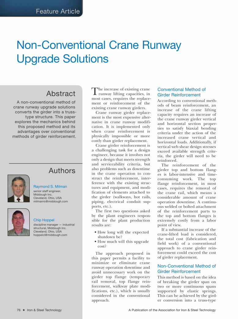
Abstract Authors 76 ✦ Iron & Steel Technology A Publication of the Association for Iron & Steel Technology T he increase of existing crane runway lifting capacities, in most cases, requires the replace- ment or reinforcement of the existing crane runway girders. Crane runway girder replace- ment is the most expensive alter- native in crane runway modifi- cation. It is implemented only when crane reinforcement is physically impossible or more costly than girder replacement. Crane girder reinforcement is a challenging task for a design engineer, because it involves not only a design that meets strength and serviceability criteria, but also problems such as downtime in the crane operation to con- struct the reinforcement, inter- ference with the existing struc- tures and equipment, and modi- fication of elements attached to the girder (walkways, hot rails, piping, electrical conduit sup- ports, etc.). The first two questions asked by the plant engineers respon- sible for the plant production results are: • How long will the expected shutdown be? • How much will this upgrade cost? The approach proposed in this paper permits a facility to minimize or eliminate crane runway operation downtime and avoid unnecessary work on the girder top flange (temporary rail removal, top flange rein- forcement, walkway plate modi- fications, etc.), which is usually considered in the conventional approach. Conventional Method of Girder Reinforcement According to conventional meth- ods of beam reinforcement, an increase of the crane lifting capacity requires an increase of the crane runway girder vertical and horizontal section proper- ties to satisfy biaxial bending criteria under the action of the increased crane vertical and horizontal loads. Additionally, if vertical web shear design stresses exceed available strength crite- ria, the girder will need to be reinforced. The reinforcement of the girder top and bottom flang- es is labor-intensive and time- consuming work. The top flange reinforcement, in most cases, requires the removal of the crane rail, which means a considerable amount of crane operation downtime. A continu- ous welded or bolted attachment of the reinforcement parts to the top and bottom flanges is extremely costly from a labor point of view. If a substantial increase of the crane-lifted load is considered, the total cost (fabrication and field work) of a conventional approach to crane girder rein- forcement could exceed the cost of girder replacement. Non-Conventional Method of Girder Reinforcement This method is based on the idea of breaking the girder span on two or more continuous spans supported by elastic springs. This can be achieved by the gird- er conversion into a truss-type Non-Conventional Crane Runway Upgrade Solutions A non-conventional method of crane runway upgrade solutions converts the girder into a truss- type structure. This paper explores the mechanics behind this proposed method and its advantages over conventional methods of girder reinforcement. Raymond S. Milman senior staff engineer, Middough Inc. Cleveland, Ohio, USA [email protected] Chip Hoppel discipline manager — industrial structural, Middough Inc. Cleveland, Ohio, USA [email protected]
Transcript of Non-Conventional Crane Runway Upgrade Solutions · 78 Iron & Steel Technology A Publication of the...
Abstract
Authors
76 ✦ Iron & Steel Technology A Publication of the Association for Iron & Steel Technology
The increase of existing crane runway lifting capacities, in
most cases, requires the replace-ment or reinforcement of the existing crane runway girders.
Crane runway girder replace-ment is the most expensive alter-native in crane runway modifi-cation. It is implemented only when crane reinforcement is physically impossible or more costly than girder replacement.
Crane girder reinforcement is a challenging task for a design engineer, because it involves not only a design that meets strength and serviceability criteria, but also problems such as downtime in the crane operation to con-struct the reinforcement, inter-ference with the existing struc-tures and equipment, and modi-fication of elements attached to the girder (walkways, hot rails, piping, electrical conduit sup-ports, etc.).
The first two questions asked by the plant engineers respon-sible for the plant production results are:
• How long will the expected shutdown be?
• How much will this upgrade cost?
The approach proposed in this paper permits a facility to minimize or eliminate crane runway operation downtime and avoid unnecessary work on the girder top flange (temporary rail removal, top flange rein-forcement, walkway plate modi-fications, etc.), which is usually considered in the conventional approach.
Conventional Method of Girder ReinforcementAccording to conventional meth-ods of beam reinforcement, an increase of the crane lifting capacity requires an increase of the crane runway girder vertical and horizontal section proper-ties to satisfy biaxial bending criteria under the action of the increased crane vertical and horizontal loads. Additionally, if vertical web shear design stresses exceed available strength crite-ria, the girder will need to be reinforced.
The reinforcement of the girder top and bottom flang-es is labor-intensive and time-consuming work. The top flange reinforcement, in most cases, requires the removal of the crane rail, which means a considerable amount of crane operation downtime. A continu-ous welded or bolted attachment of the reinforcement parts to the top and bottom flanges is extremely costly from a labor point of view.
If a substantial increase of the crane-lifted load is considered, the total cost (fabrication and field work) of a conventional approach to crane girder rein-forcement could exceed the cost of girder replacement.
Non-Conventional Method of Girder ReinforcementThis method is based on the idea of breaking the girder span on two or more continuous spans supported by elastic springs. This can be achieved by the gird-er conversion into a truss-type
Non-Conventional Crane Runway Upgrade Solutions
A non-conventional method of crane runway upgrade solutions converts the girder into a truss-
type structure. This paper explores the mechanics behind
this proposed method and its advantages over conventional
methods of girder reinforcement.
Raymond S. Milmansenior staff engineer, Middough Inc.Cleveland, Ohio, USA [email protected]
Chip Hoppeldiscipline manager — industrial structural, Middough Inc. Cleveland, Ohio, USA [email protected]

AIST.org June 2012 ✦ 77
structure, where the girder performs the function of the top chord of the truss.
All components of the reinforcement truss (bottom chord, diagonals and posts) are shop-fabricated and installed below the girder bottom flange, using bolted connections to the girder and the columns.
Sizing of the reinforcement truss members is per-formed based on the analysis of the modified girder system as an elastic frame. A computer program with moving load features can be a convenient tool to determine a force envelope for each member of the system. By changing the sizes of the new reinforce-ment members, the designer could achieve a desirable force distribution between the existing crane girder and the new reinforcement members.
The installation of the truss-type modification also has a positive effect on the crane columns. It increases column stability against out-of-plane buckling, which could govern the crane column design. In addition, it reduces the crane maximum vertical load on the girder seat due to shear redistribution effect.
This approach of crane girder reinforcement is extremely effective for small- and medium-span gird-ers of 20–40 feet long. However, the conversion of two 25' 0" girders into a 50' 0" span structure and crane upgrade from 50 to 75 tons has been performed recently (Figure 1).
The only deficiency of the girder-into-truss con-version method is a requirement of available space below the crane girder bottom flange to install the reinforcement details. If the space below the girder bottom flange is limited, a second approach — the girder load sharing method — is applicable.
An example of the crane load sharing between the crane girder and a new beam installed below the crane girder is shown in Figure 2c. The size of the reinforcement beam can be determined by the analy-sis of the double beam system.
The following examples demonstrate a design appli-cation of the non-conventional crane girder reinforce-ment approach.
Example No. 1 — It is proposed to replace the exist-ing 50-ton crane with a new 80-ton crane. The crane wheel vertical loads will be increased from the pres-ent 64 kips to 89.5 kips, and the horizontal side truss wheel loads will be increased from the existing 5 kips to 8 kips (per AIST’s Technical Report No. 13, 2003 edition).
The existing crane runway 25' 0" girder is a built-up riveted girder made of Fy = 33 ksi steel.
Allowable bending stresses:
• Top flange Fbx = 0.66 Fy = 21.8 ksi, Fby = 0.6 Fy = 19.8 ksi
• Bottom flange Fbx = 0.6 Fy = 19.8 ksi• Allowable shear stress Fs = 0.4 Fy = 13.2 ksi
Design stress in the existing girder due to action of the 80-ton crane:
• Top flange fbx = 22.4 ksi with impact, fby = 6.1 ksiCombined biaxial bending checking per AIST TR
No. 13, Equation 5.1 for the top flange:
22 4
21 8
6 1
19 81 03 0 31 1 34 1 0
.
.
.
.. . . .
design limit exceeded
(Eq. 1)
• Bottom flange fbx = 27.7 ksi with impact > 19.8 ksi,which is too high.
• Vertical web shear fa = 16.2 ksi > 13.2 ksi which is too high.
The crane girder reinforcement analyses were per-formed using Structural Analysis and Design Software (STAAD-III). The crane runway was modeled as a longitudinal frame loaded with moving crane loads.
Truss-Type Girder Reinforcement — After several computer program runs with various member proper-ties for diagonals and struts, the optimal diagonals 2L’s 6 x 6 x 5/8, steel ASTM 572, Grade 50 were chosen for design.
Analysis results (Figure 2b):
• Mmax. vert. = 694.5 ft~kips vs. 1,494 ft~kips for single-span girder (Figure 2b).
• Vmax. vert. = 212.6 kips vs. 291 kips for single-span girder (Figure 2a).
• Top flange fbx = 10.3 ksi with impact fby = 5.6 ksi
Combined biaxial bending checking per AIST TR No. 13, Equation 5.1 for the top flange:
10 3
21 8
5 6
19 80 47 0 28 0 75 1 0
.
.
.
.. . . .
design limit not exceeded(Eq. 2)
• Vertical shear Fs = 11.8 ksi < 13.2 ksi is also within limits
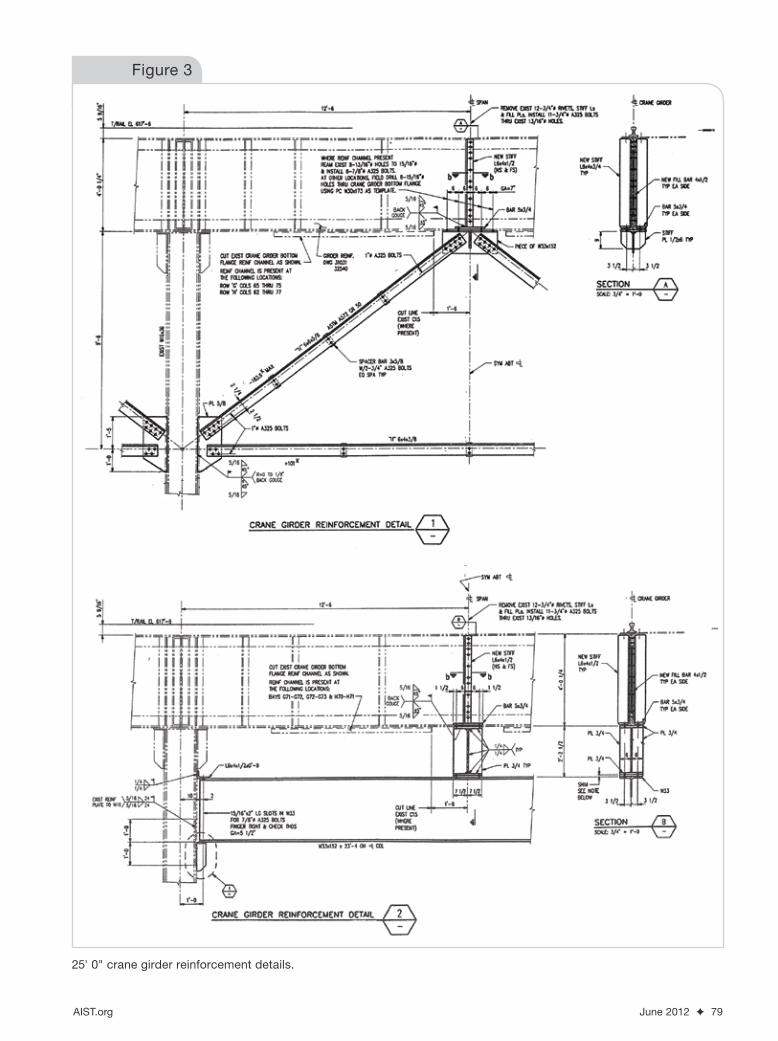
Reinforcement detail is shown in Figure 3 — Detail 1.
Column removal and mid-span reinforcement.
Figure 1

78 ✦ Iron & Steel Technology A Publication of the Association for Iron & Steel Technology
Crane Load Sharing With Mid-Span Support Beam — Crane girders located over the entrance door and over the electrical room do not have enough space to install the truss-type reinforcement. An installation of the load-sharing beam requires substantially less space below the girder.
Analysis results (Figure 2c):
• After a few attempts, a proper size of the support beam was accepted as W33 x 152.
• Load distribution between the existing girder and the W33 support beam are shown in Table 1.
Reinforced girder checking:
• Top flange fbx = 13.5 ksi with impact fby = 5.6 ksi
Combined biaxial bending checking per AIST TR No. 13, Equation 5.1 for the top flange:
13 5
21 8
5 6
19 80 62 0 28 0 90
.
.
.
.. . .
(Eq. 3)
Since 0.9 < 1.0, limit is not exceeded.
• Vertical shear Fs = 12.7 ksi < 13.2 ksi within limits.• W33 support beam checking – fbx = 16.5 ksi <
21.6 ksi within limits.
Reinforcement detail is shown on Figure 3 — Detail 2.
Example No. 2 — It was proposed to replace the exist-ing 15-ton crane with a new 25-ton crane. The design crane wheel load increased from 39.5 kips to 56 kips. The 42' 3" crane girder consists of W33 x 132 with a cap channel MC18 x 42.7 (steel Fy = 33 ksi).
Allowable bending stresses:
• Top flange Fbx = 15.7 ksi (ASD 89, Eq. F 1-6)• Bottom flange Fbx = 0.6 Fy = 19.8 ksi
Design stresses in the existing girder due to action of the 25-ton crane:
• Top flange fbx = 17.8 ksi with impact > 15.7 ksi exceeds limits.
• Bottom flange fbx = 27.8 ksi with impact > 19.8 ksi exceeds limits.
Horizontally, the top flange is well braced, and the vertical shear design stresses are within allowable limits.
Solution No. 1: Replace the girder — The built-up girder, W36 x 194 with MC18 x 42.7 cap channel, satisfies design loads.
Solution No. 2: Reinforce the girder — It is proposed to reinforce the girder with a sub-diagonal frame, as shown schematically in Figure 4.
After a few attempts, the optimal sizes of the rein-forcement frame (diagonals, posts and a strut) were chosen: 2 L’s 6 x 4 x 3/8.
Figure 4 shows the maximum vertical bending moments and axial forces in the existing and modi-fied systems for different crane positions. The maxi-mum bending moment in the existing girder is reduced from 1,040 ft~kips to 408 ft~kips, with a small compression force of 74.4 kips (stress = 1.5 ksi). This results in a top flange bending stress fbx = 7.0 ksi and a bottom flange bending stress fbx = 10.9 ksi.
Checking for biaxial bending, shear and fatigue-related stress ranges proved that the reinforced girder meets the strength criteria for the 25-ton crane loads.
Solution No. 2 was implemented (Figure 5). The methods presented in this paper have been
implemented in several projects, resulting in signifi-cant economic effects.
Figures 5–7 illustrate a few examples of non-conven-tional crane girder reinforcements.
Table 1
Load Distribution Between Existing Girder and W33 Support Beam
Existing girder W33 x 152
Vertical bending 904 671 Mmax (ft~kip)
Vertical shear 228 54 Vmax (kip)
25’ 0” crane girder reinforcement.
Figure 2
AIST.org June 2012 ✦ 79
25' 0" crane girder reinforcement details.
Figure 3

80 ✦ Iron & Steel Technology A Publication of the Association for Iron & Steel Technology
SummaryThe approach demonstrated in this paper for crane runway girder reinforcement provides the follow-ing advantages over conventional crane girder reinforcement:
• This method permits a substantial increase in the crane runway lifting capacity.
• All field work of girder reinforcement is per-formed below the crane runway. This permits installation of the reinforcement details with short, if any, interruptions in crane operations.
• No crane rail removal is required, unless rail replacement is scheduled.
• Labor-consuming field work is mini-mized, because all structural elements are shop-fabricated.
• No girder bottom flange attachment and/or hot rail support relocation is required.
• A significant reduction of the girder vertical bending stresses permits an increase of the top flange horizontal bending stresses without exceeding overall biaxial bending criteria. ✦
Nominate this paperDid you find this article to be of significant relevance to the advancement of steel technology? If so, please consider nominating it for the AIST Hunt-Kelly Outstanding Paper Award at AIST.org/huntkelly.
This paper was presented in June 2011 at the 18th Annual Crane Symposium, Pittsburgh, Pa.
Truss-type reinforcement (example 2).
Figure 5
Truss-type reinforcement.
Figure 7
Truss-type reinforcement.
Figure 6
42’ 3” crane girder reinforcement.
Figure 4