Non-contact measurement with capacitive and inductive … · Lion Precision is the market leader in...
24
Non-contact measurement with capacitive and inductive systems Version 02/07
Transcript of Non-contact measurement with capacitive and inductive … · Lion Precision is the market leader in...
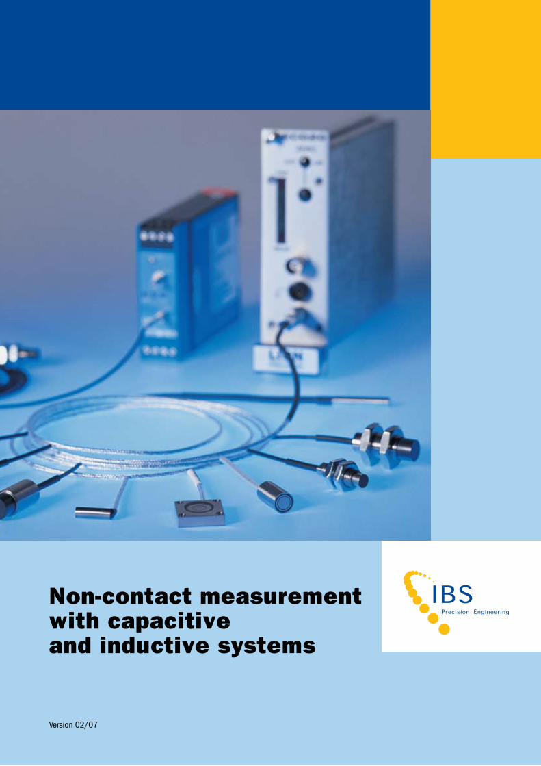
Non-contact measurementwith capacitive and inductive systems
version 02/07
Technology
Precision engineering demands the expertise of an authority, particularly when you want to carry out measurements for which there are as yet no solutions. What you then need to do is find technology that can guarantee maximum precision. IBS Precision Engineering offers more and better solutions – right down to the level of micrometres and nanometres.
We don’t just focus in on existing technology but also on technology that’s still being developed.
By linking the two, we can create solutions that amount to more than the sum of their parts and that go further than usual. They’re tried and tested and have been constructed by specialists, including the software and support.
Take a look at precision technology through the eyes of IBS Precision Engineering – it will greatly increase the options available to you. you’ll be just as surprised as Antonie van Leeuwenhoek, whose microscopes opened up a whole new world.
Antonie van Leeuwenhoek was
a renowned Dutch naturalist.
Using lenses and silver plates
that he ground and polished
himself, he constructed
microscopes that enabled him
to make numerous important
discoveries. He was the first
to observe such things as
bacteria, the striations in
muscle fibres, and the nucleus
of red blood corpuscles in fish.
van Leeuwenhoek is
considered to be the founding
father of microbiology.
In 1680, he was admitted to
membership of the prestigious
royal Society in London.
Antonie vAnleeuwenhoek
Dutch naturalist (1632 - 1723)
[ 2 ]
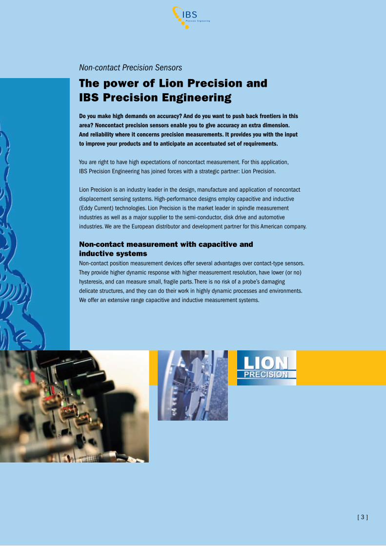
The power of Lion Precision and IBS Precision Engineering
Non-contact Precision Sensors
Do you make high demands on accuracy? And do you want to push back frontiers in this area? Noncontact precision sensors enable you to give accuracy an extra dimension. And reliability where it concerns precision measurements. It provides you with the input to improve your products and to anticipate an accentuated set of requirements.
you are right to have high expectations of noncontact measurement. For this application, IBS Precision Engineering has joined forces with a strategic partner: Lion Precision.
Lion Precision is an industry leader in the design, manufacture and application of noncontact displacement sensing systems. High-performance designs employ capacitive and inductive (Eddy Current) technologies. Lion Precision is the market leader in spindle measurement industries as well as a major supplier to the semi-conductor, disk drive and automotive industries. We are the European distributor and development partner for this American company.
Non-contact measurement with capacitive and inductive systemsNon-contact position measurement devices offer several advantages over contact-type sensors. They provide higher dynamic response with higher measurement resolution, have lower (or no) hysteresis, and can measure small, fragile parts. There is no risk of a probe’s damaging delicate structures, and they can do their work in highly dynamic processes and environments.We offer an extensive range capacitive and inductive measurement systems.
[ 3 ]
Consider two parallel steel plates with a gap between them. When a voltage is applied to one of the plates, the difference between the charges stored on the surfaces of the plates will cause an electric field to exist between them. This is a parallel-plate capacitor. Capacitance describes how the space between the two conductors affects an electric field between them, and refers to the capacity of the two plates to hold this charge. A large capacitance can hold more charge than a small one. The amount of existing charge determines the amount of current required to change the voltage on the plate.
Capacitance is measured in Farads, after Michael Faraday (1791–1867), an English physicist and chemist who did pioneering work in electricity and magnetism. One Farad is a large unit; a typical capacitor used in electronic circuitry is measured in microFarads. The capacitance changes sensed in a typical capacitive sensor are femtoFarads.
OFF ON
HI LO
SENSITIvITy
NEAr
FAr
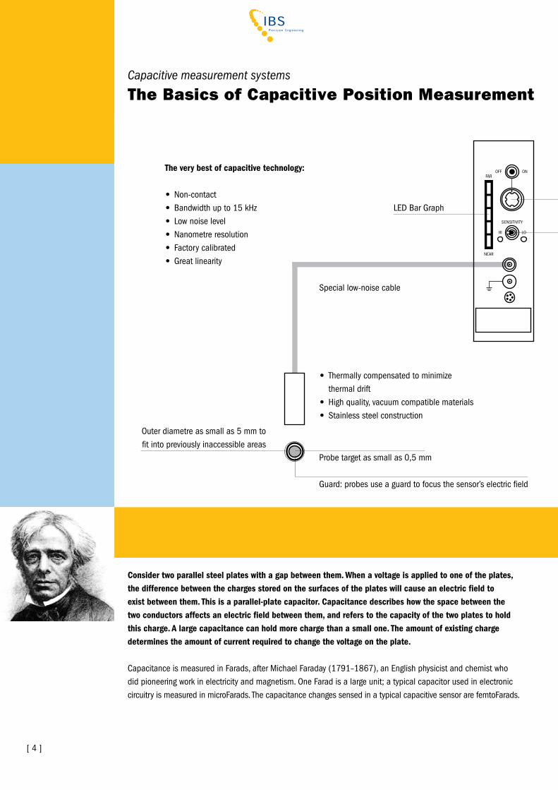
Capacitive measurement systems
The Basics of Capacitive Position Measurement
The very best of capacitive technology:
• Non-contact• Bandwidth up to 15 kHz• Low noise level• Nanometre resolution• Factory calibrated• Great linearity
Special low-noise cable
LED Bar Graph
Outer diametre as small as 5 mm to fit into previously inaccessible areas
Probe target as small as 0,5 mm
Guard: probes use a guard to focus the sensor’s electric field
• Thermally compensated to minimize thermal drift• High quality, vacuum compatible materials• Stainless steel construction
[ 4 ]
In a capacitive position sensor, the electrified plate is the sensor surface and the second plate is the target. The electronics continuously change the voltage on the sensor surface. This is the excitation voltage. The amount of current required to change the voltage is detected by the electronics and indicates the amount of capacitance between sensor and target. An AC bridge circuit or other active electronic circuit is typically used to convert the capacity change into a current or voltage signal and output.
In ordinary capacitance-based position measurement, the size of the sensor and the target, and the dielectric medium (usually air) remain constant. The only variable is the gap. All changes in capacitance are therefore the result of a change in the position of the target relative to the sensor. The driver is calibrated and the output scaled to provide a specific voltage for a corresponding change in capacitance (i.e., gap or displacement).
Target Material and ThicknessThe sensor’s electric field seeks a conductive surface, meaning that these transducers are not affected by target material (magnetic, nonmagnetic) provided that it is a conductor. Because the electric field resides at the surface of the conductor, target thickness is not important.
EnvironmentAlthough capacitive transducers are not affected by material magnetic properties, they are sensitive to the medium in the gap between the sensor and the target. Maintaining a steady dielectric constant in the gap is therefore important—and humidity affects the dielectric constant of air. The dielectric constant of air increases with humidity and will change the capacitance between sensor and target.
Furthermore, moisture and other fluids can migrate into the sensor and negatively interact with its construction. Capacitive transducers are therefore not recommended for applications characterized by excessive dirt, dust, water, machining fluids, or oils.
Summarizing the advantages of Lion Precision capacitive measurement systems
• Non-contact• High bandwidth, very low noise level• Sub-nanometre resolution• Great linearity• No heat generation on the sensing point• No electrical runout at spindle measurement• Thermally compensated to minimize thermal drift• vacuum compatible
Probe target as small as 0,5 mm
Guard: probes use a guard to focus the sensor’s electric field
Dual range(user selectable)
Fine/Coarse zeroadjustment
[ 5 ]

Lion Precision capacitive measurement systems
[ 6 ]
Probe RangesMost probes have several different calibration rangesExtended Maximum measurement rangeStandard Standard rangeFine Finer range, higher resolution (~10 % of standard range)Ultrafine Ultrafine range, highest resolution (~2% of standard range)(The Compact Driver only offers the Standard and Fine calibrations.)
ProbesThe two primary aspects of a probe are body style and sensor area. A probe model number indicates these two aspects. For example, a C23-B probe is a C23 body style with a B size sensor diameter.
Probe Features• Special low-noise cable• Thermally compensated to minimize thermal drift vacuum compatible materials
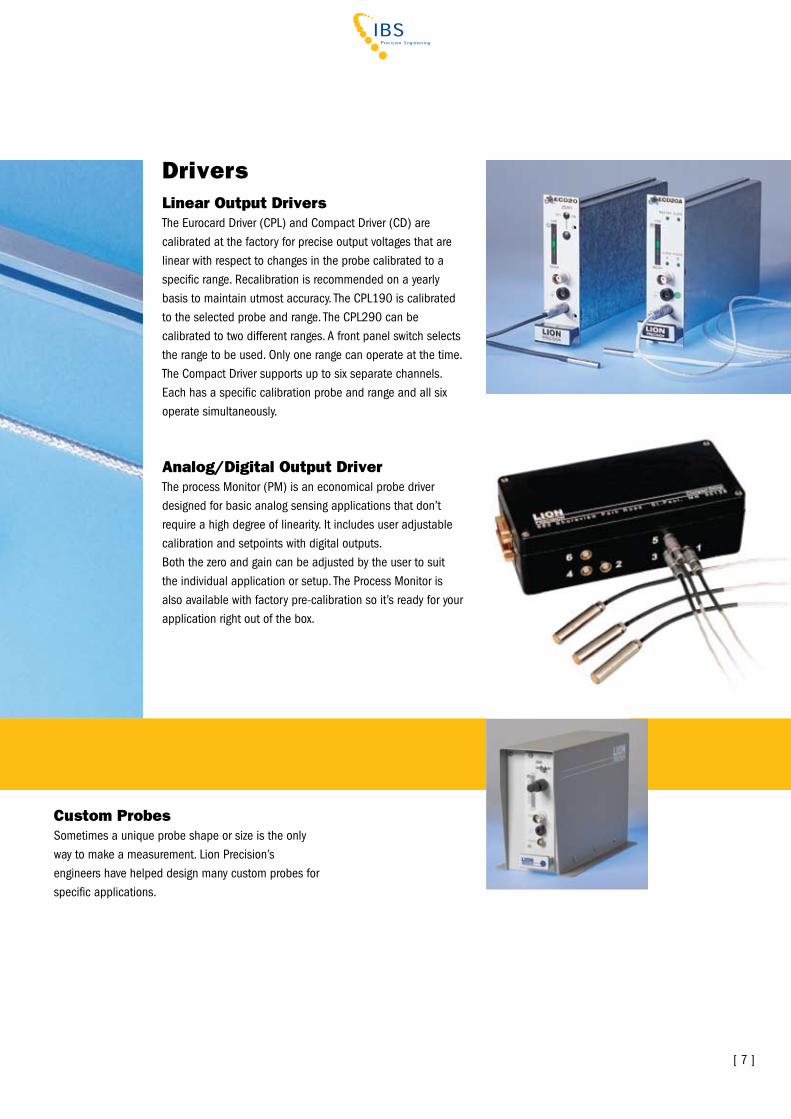
Linear Output DriversThe Eurocard Driver (CPL) and Compact Driver (CD) are calibrated at the factory for precise output voltages that are linear with respect to changes in the probe calibrated to a specific range. recalibration is recommended on a yearly basis to maintain utmost accuracy. The CPL190 is calibrated to the selected probe and range. The CPL290 can be calibrated to two different ranges. A front panel switch selects the range to be used. Only one range can operate at the time. The Compact Driver supports up to six separate channels. Each has a specific calibration probe and range and all six operate simultaneously.
Analog/Digital Output DriverThe process Monitor (PM) is an economical probe driver designed for basic analog sensing applications that don’t require a high degree of linearity. It includes user adjustable calibration and setpoints with digital outputs.Both the zero and gain can be adjusted by the user to suit the individual application or setup. The Process Monitor is also available with factory pre-calibration so it’s ready for your application right out of the box.
Drivers
[ 7 ]
Custom ProbesSometimes a unique probe shape or size is the only way to make a measurement. Lion Precision’s engineers have helped design many custom probes for specific applications.
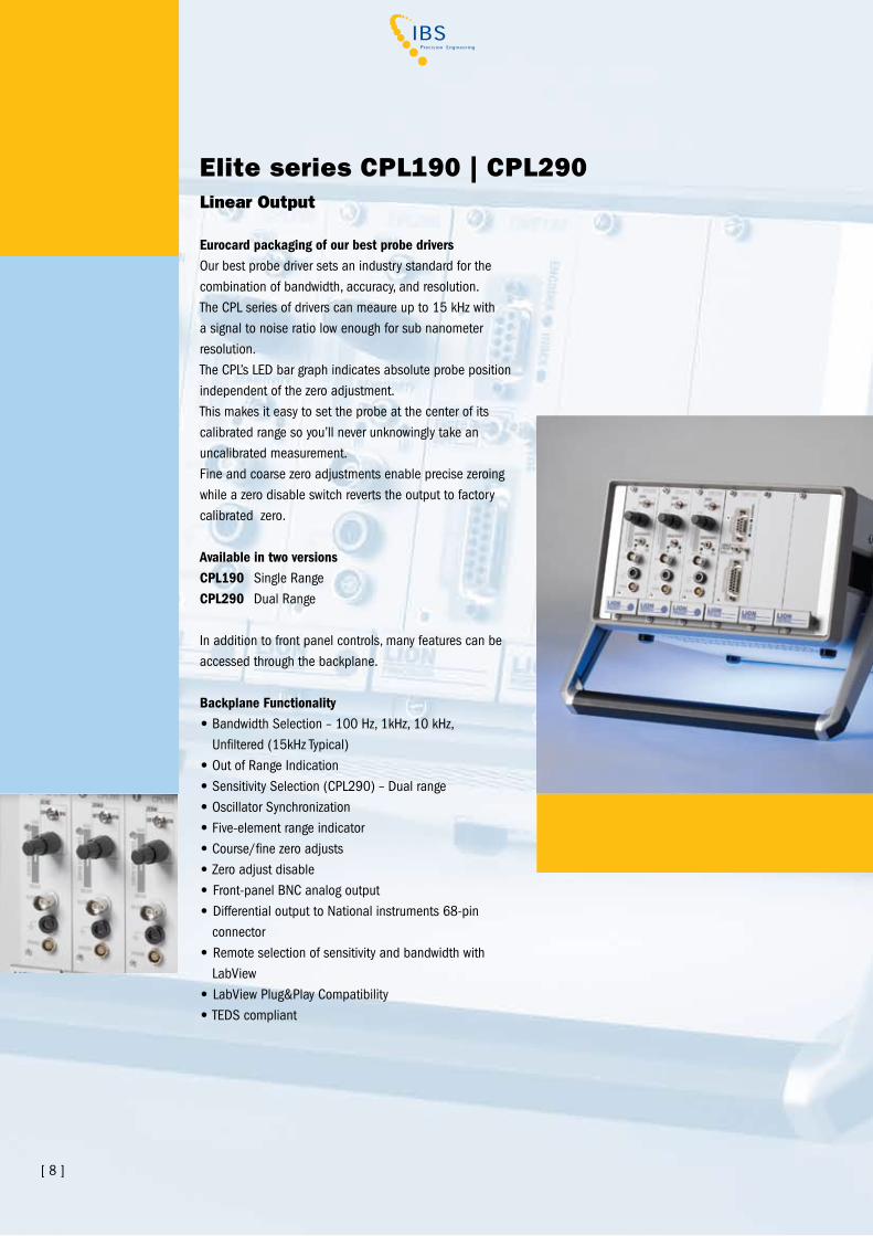
Elite series CPL190 | CPL290Linear Output
Eurocard packaging of our best probe driversOur best probe driver sets an industry standard for the combination of bandwidth, accuracy, and resolution. The CPL series of drivers can meaure up to 15 kHz with a signal to noise ratio low enough for sub nanometer resolution.The CPL’s LED bar graph indicates absolute probe position independent of the zero adjustment. This makes it easy to set the probe at the center of its calibrated range so you’ll never unknowingly take an uncalibrated measurement.Fine and coarse zero adjustments enable precise zeroing while a zero disable switch reverts the output to factory calibrated zero.
Available in two versionsCPL190 Single rangeCPL290 Dual range
In addition to front panel controls, many features can be accessed through the backplane.
Backplane Functionality• Bandwidth Selection – 100 Hz, 1kHz, 10 kHz, Unfiltered (15kHz Typical)• Out of range Indication• Sensitivity Selection (CPL290) – Dual range• Oscillator Synchronization• Five-element range indicator• Course/fine zero adjusts• Zero adjust disable• Front-panel BNC analog output• Differential output to National instruments 68-pin connector• remote selection of sensitivity and bandwidth with Labview• Labview Plug&Play Compatibility• TEDS compliant
[ 8 ]

[ 9 ]
Our top performing capacitive sensor systemElite series sensors combine high performance, easy DAQ interface and the flexibility of custom configurations.• 1 - 8 sensors in a single system• Sensors Plug&Play (TEDS) for easy Labview interface• Support Modules available: Temperature Sensors, Signal Processing/Display
EnclosuresIntelligent enclosures.Enclosures provide power and drive signals.Extra slots can be specified for future expansion.• Direct connect to National Instruments hardware DAQ hardware• Input power: 100-240 vAC 50/60Hz• 1-, 2-, 3-, 6-, 8-slots options• Mounting flanges on 1-, 2-, and 3-slot• Tip-up handle on 6- and 8-slot
Elite series enclosures
2-slot enclosure
3-slot enclosure
1-slot enclosure
8-slot enclosure

MM190
Signal processing and five-digit display moduleTwo-channel summing and peak-capture functions• Five-digit display: metric or inch functions• Summing: A, B, A+B, A-B of any two channels in the system• Peak-capture functions: Max, Min, TIr, Tracking TIr (Self-resetting TIR)• Analog output of conditioned signal through BNC• Differential, analog output of conditioned signal through National Instruments 68-pin connector• Display accuracy: 0.1%
[ 10 ]
TMP190
Index and temperature moduleUsed in conjunction with Labview or Lion Precision SEA v8 software to read temperature sensors and encoder/index inputs.• Seven thermistors included• Index and encoder inputs for SEA• +5v and +15v encoder/prox power• Single-ended or differential encoder input• Encoder and index state indicators
Optional Elite Modules
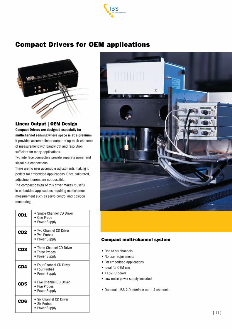
Linear Output | OEM DesignCompact Drivers are designed especially for multichannel sensing where space is at a premium It provides accurate linear output of up to six channels of measurement with bandwidth and resolution sufficient for many applications.Two interface connectors provide separate power and signal out connections.There are no user accessible adjustments making it perfect for embedded applications. Once calibrated, adjustment errors are not possible.The compact design of this driver makes it useful in embedded applications requiring multichannel measurement such as servo control and position monitoring.
Compact Drivers for OEM applications
CD1
CD2
CD3
CD4
CD5
CD6
• Single Channel CD Driver• One Probe• Power Supply
• Two Channel CD Driver• Two Probes• Power Supply
• Three Channel CD Driver• Three Probes• Power Supply
• Four Channel CD Driver• Four Probes• Power Supply
• Five Channel CD Driver• Five Probes• Power Supply
• Six Channel CD Driver• Six Probes• Power Supply
Compact multi-channel system
• One to six channels• No user adjustments• For embedded applications• Ideal for OEM use• ±15vDC power• Low-noise power supply included
• Optional: USB 2.0 interface up to 4 channels
[ 11 ]
[ 12 ]
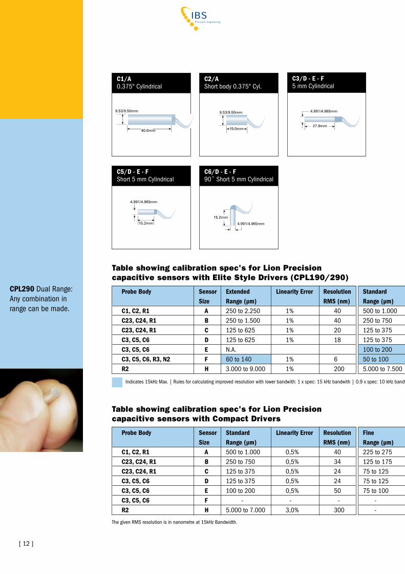
CPL290 Dual range:Any combination inrange can be made.
Probe Body Sensor Extended Linearity Error Resolution Size Range (µm) RMS (nm)C1, C2, R1 A 250 to 2.250 1% 40C23, C24, R1 B 250 to 1.500 1% 40C23, C24, R1 C 125 to 625 1% 20C3, C5, C6 D 125 to 625 1% 18C3, C5, C6 E N.A. C3, C5, C6, R3, N2 F 60 to 140 1% 6R2 H 3.000 to 9.000 1% 200
Standard Linearity Error Resolution Range (µm) RMS (nm)500 to 1.000 0,3% 12250 to 750 0,3% 14125 to 375 0,3% 10125 to 375 0,3% 9100 to 200 0,3% 1550 to 100 0,3% 55.000 to 7.500 0,3% 100
C1/A0.375" Cylindrical
C2/AShort body 0.375" Cyl.
C3/D - E - F5 mm Cylindrical
C5/D - E - FShort 5 mm Cylindrical
Table showing calibration spec's for Lion Precision capacitive sensors with Elite Style Drivers (CPL190/290)
Table showing calibration spec's for Lion Precision capacitive sensors with Compact Drivers
Fine Linearity Error Resolution Range (µm) RMS (nm)225 to 275 0,3% 5125 to 175 0,3% 575 to 125 0,3% 575 to 125 0,3% 575 to 100 0,3% 15 - - - - - -
Probe Body Sensor Standard Linearity Error Resolution Size Range (µm) RMS (nm)C1, C2, R1 A 500 to 1.000 0,5% 40C23, C24, R1 B 250 to 750 0,5% 34C23, C24, R1 C 125 to 375 0,5% 24C3, C5, C6 D 125 to 375 0,5% 24C3, C5, C6 E 100 to 200 0,5% 50 C3, C5, C6 F - - -R2 H 5.000 to 7.000 3,0% 300
The given rMS resolution is in nanometre at 15kHz Bandwidth.
C6/D - E - F90˚ Short 5 mm Cylindrical
Indicates 15kHz Max. | rules for calculating improved resolution with lower bandwith: 1 x spec: 15 kHz bandwith | 0.9 x spec: 10 kHz bandwith | 0.7 x spec: 1 kHz bandwith | 0.5 x spec: 100 Hz bandwith
[ 13 ]
Fine Linearity Error Resolution Range (µm) RMS (nm)225 to 275 0,5% 1,2125 to 175 0,5% 2,275 to 125 0,5% 2,475 to 125 0,5% 2,175 to 100 0,5% 520 to 30 0,5% 1,5 - - -
Standard Linearity Error Resolution Range (µm) RMS (nm)500 to 1.000 0,3% 12250 to 750 0,3% 14125 to 375 0,3% 10125 to 375 0,3% 9100 to 200 0,3% 1550 to 100 0,3% 55.000 to 7.500 0,3% 100
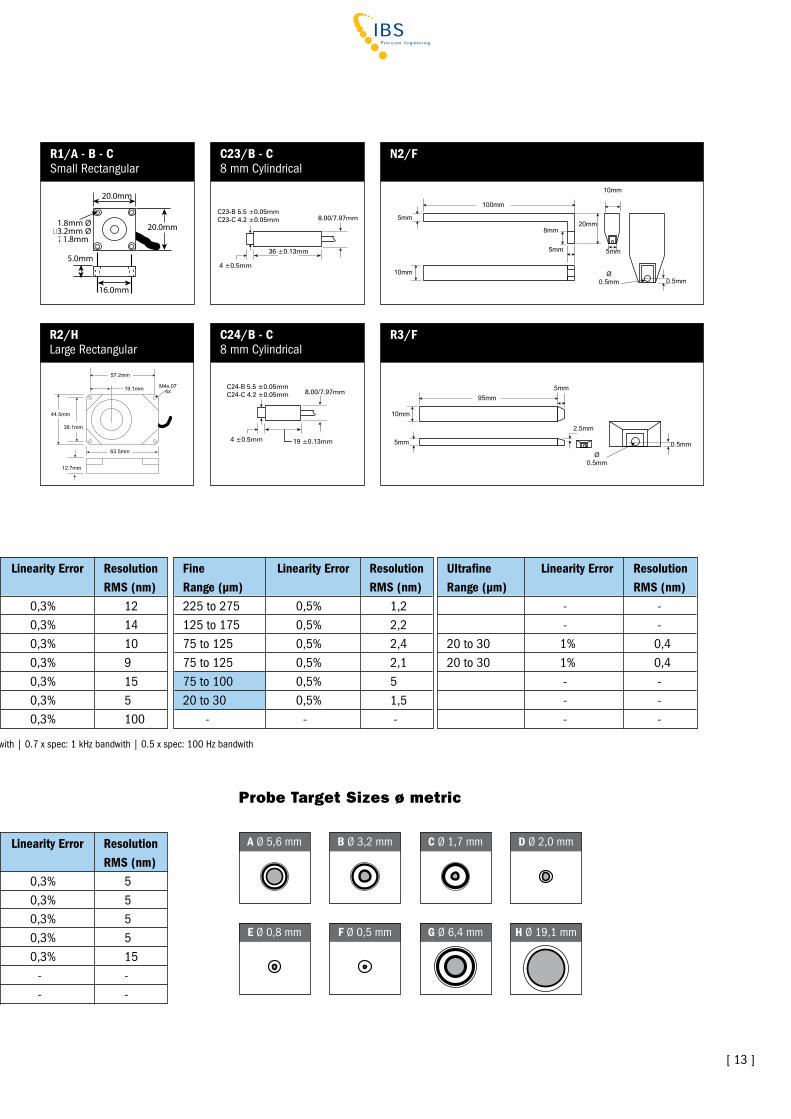
R1/A - B - CSmall rectangular
57.2mm
19.1mm M4x.074x
38.1mm
44.5mm
63.5mm
12.7mm
R2/HLarge rectangular
Probe Target Sizes ø metric
A Ø 5,6 mm
E Ø 0,8 mm
B Ø 3,2 mm
F Ø 0,5 mm
C Ø 1,7 mm
G Ø 6,4 mm
D Ø 2,0 mm
H Ø 19,1 mm
Ultrafine Linearity Error Resolution Range (µm) RMS (nm) - - - -20 to 30 1% 0,420 to 30 1% 0,4 - - - - - -
Table showing calibration spec's for Lion Precision capacitive sensors with Elite Style Drivers (CPL190/290)
Fine Linearity Error Resolution Range (µm) RMS (nm)225 to 275 0,3% 5125 to 175 0,3% 575 to 125 0,3% 575 to 125 0,3% 575 to 100 0,3% 15 - - - - - -
The given rMS resolution is in nanometre at 15kHz Bandwidth.
N2/F
Ø0.5mm
10mm
10mm
100mm
5mm5mm
0.5mm
8mm20mm
5mm
95mm
5mm
Ø0.5mm
2.5mm
10mm
5mm 0.5mm
R3/F
Indicates 15kHz Max. | rules for calculating improved resolution with lower bandwith: 1 x spec: 15 kHz bandwith | 0.9 x spec: 10 kHz bandwith | 0.7 x spec: 1 kHz bandwith | 0.5 x spec: 100 Hz bandwith
C23/B - C8 mm Cylindrical
36 ±0.13mm
8.00/7.97mm
4 ±0.5mm
C23-B 5.5 ±0.05mmC23-C 4.2 ±0.05mm
C24/B - C8 mm Cylindrical
19 ±0.13mm
8.00/7.97mm
4 ±0.5mm
C24-B 5.5 ±0.05mmC24-C 4.2 ±0.05mm
[ 14 ]
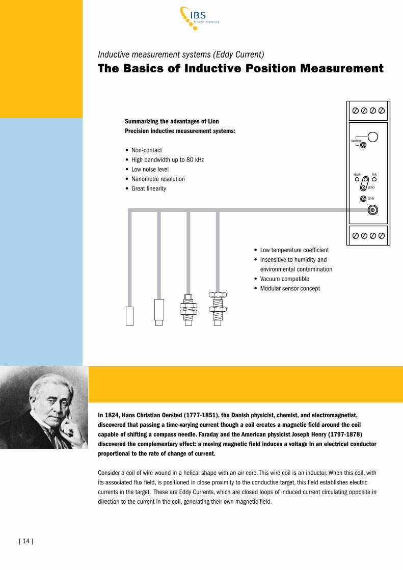
In 1824, Hans Christian Oersted (1777-1851), the Danish physicist, chemist, and electromagnetist, discovered that passing a time-varying current though a coil creates a magnetic field around the coil capable of shifting a compass needle. Faraday and the American physicist Joseph Henry (1797-1878) discovered the complementary effect: a moving magnetic field induces a voltage in an electrical conductor proportional to the rate of change of current.
Consider a coil of wire wound in a helical shape with an air core. This wire coil is an inductor. When this coil, with its associated flux field, is positioned in close proximity to the conductive target, this field establishes electric currents in the target. These are Eddy Currents, which are closed loops of induced current circulating opposite in direction to the current in the coil, generating their own magnetic field.
SWITCH
NEAr FAr
ZErO
GAIN
Inductive measurement systems (Eddy Current)
The Basics of Inductive Position Measurement
• Low temperature coefficient• Insensitive to humidity and environmental contamination• vacuum compatible• Modular sensor concept
Summarizing the advantages of Lion Precision inductive measurement systems:
• Non-contact• High bandwidth up to 80 kHz • Low noise level• Nanometre resolution• Great linearity

Eddy Currents normally travel parallel to the coil windings and parallel to the target surface. Eddy Current flow is limited to the area in the target within the inducing magnetic field.
The magnetic flux associated with the Eddy Currents opposes the coil's magnetic flux. Decreasing target-to-coil gap changes inductance of the coil, thereby changing net flux of the system. This results in a change in coil impedance and a voltage change across the coil. It is this interaction between the coil and Eddy Current fields that provides the basis for determining target-to-coil position information with an Eddy Current position measurement transducer. As shown, coil impedance is dependent upon inductance, which is a function of frequency, coil resistance, and target material properties.
For Eddy Current position measurement transducers, coil oscillation frequency is typically between 100’s of kHz and several MHz. Higher frequency limits probe to driver cable length, and lower frequency reduces field strength and can limit measurement performance. An AC-bridge circuit or other active electronic circuit can be employed for detecting this changing coil signal.
Environment Inductive position sensors, while sensitive to target material properties, are not affected by nonconductive materials in the sensor-to-target gap. This feature offers distinct advantages in dirty environments (e.g., dirt, dust, water, and machining fluids and oils), assuming that the sensor is designed and built to withstand these fluids.
The quality of inductive (Eddy Current) probe-to-target field coupling is significantly dependent upon the electrical resistance and magnetic permeability of the target. This coupling determines the magnitude of coil impedance change vs. displacement. Thus, the quality of the resulting measurement relies heavily upon the target material used.
The ideal target material for Eddy Current position measurement transducers are nonferrous materials with low electrical resistance, materials like aluminium, brass, and copper. But also other target materials can be used efficiently. The optimum performance is achieved when the transducer is calibrated against the actual target material to be used in the application.
[ 15 ]
• State-of-the-art electronics• Small DIN rail mounting• Probe position indicators• Local & remote zero• TEDS integrated• Synchronisation of multiple units
[ 16 ]
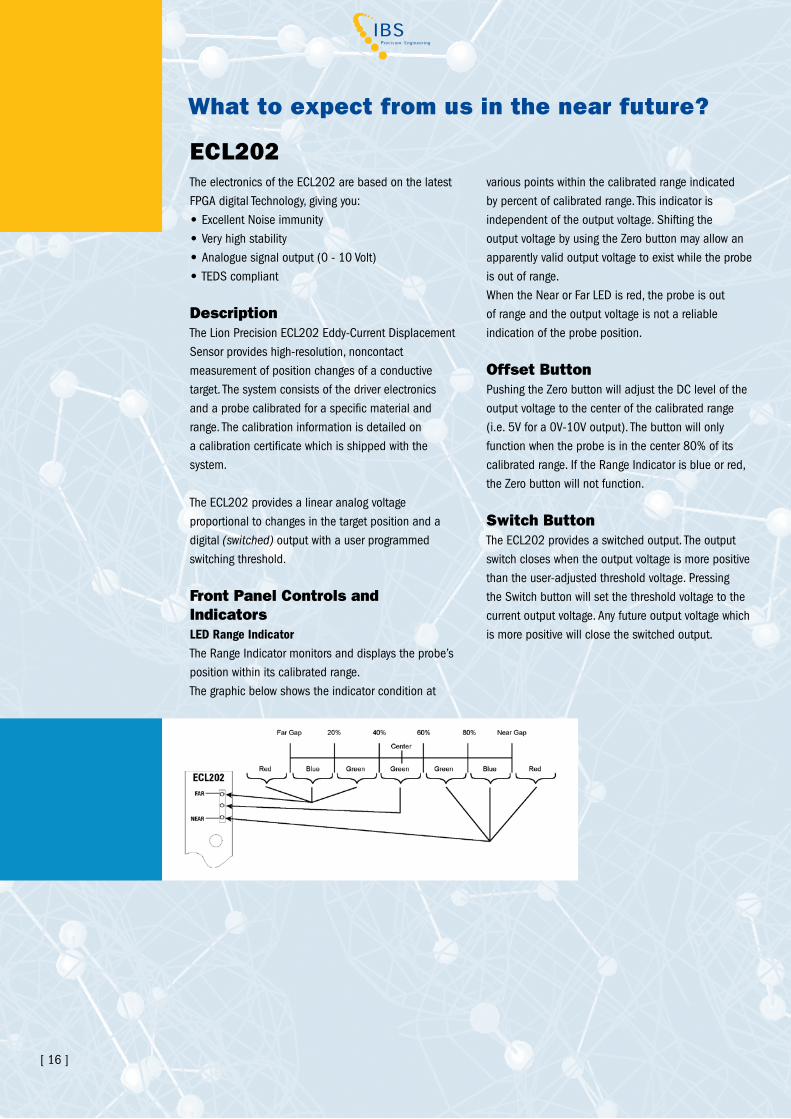
What to expect from us in the near future?
various points within the calibrated range indicated by percent of calibrated range. This indicator is independent of the output voltage. Shifting the output voltage by using the Zero button may allow an apparently valid output voltage to exist while the probe is out of range.When the Near or Far LED is red, the probe is out of range and the output voltage is not a reliable indication of the probe position.
Offset ButtonPushing the Zero button will adjust the DC level of the output voltage to the center of the calibrated range (i.e. 5v for a 0v-10v output). The button will only function when the probe is in the center 80% of its calibrated range. If the range Indicator is blue or red, the Zero button will not function.
Switch Button The ECL202 provides a switched output. The output switch closes when the output voltage is more positive than the user-adjusted threshold voltage. Pressing the Switch button will set the threshold voltage to the current output voltage. Any future output voltage which is more positive will close the switched output.
ECL202The electronics of the ECL202 are based on the latest FPGA digital Technology, giving you:• Excellent Noise immunity• very high stability• Analogue signal output (0 - 10 volt)• TEDS compliant
DescriptionThe Lion Precision ECL202 Eddy-Current Displacement Sensor provides high-resolution, noncontact measurement of position changes of a conductive target. The system consists of the driver electronics and a probe calibrated for a specific material and range. The calibration information is detailed on a calibration certificate which is shipped with the system.
The ECL202 provides a linear analog voltage proportional to changes in the target position and adigital (switched) output with a user programmed switching threshold.
Front Panel Controls and IndicatorsLED Range IndicatorThe range Indicator monitors and displays the probe’s position within its calibrated range. The graphic below shows the indicator condition at
[ 16 ] [ 17 ]
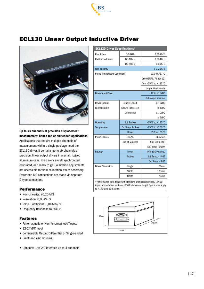
ECL130 Linear Output Inductive Driver
Up to six channels of precision displacement measurement: bench-top or embedded applicationsApplications that require multiple channels of measurement within a single package need the ECL130 driver. It contains up to six channels of precision, linear output drivers in a small, rugged aluminium case. The drivers are all synchronized, calibrated, and ready to go. Calibration adjustments are accessible for field calibration where necessary. Power and I/0 connections are made via separate D-type connectors.
Performance• Non-Linearity: ±0,25%FS• resolution: 0,004%FS• Temp. Coefficient: 0,04%FS/°C• Frequency response to 80kHz
Features• Ferromagnetic or Non-ferromagnetic Targets• 12-24vDC Input• Configurable Output Differential or Single-ended• Small and rigid housing
• Optional: USB 2.0 interface up to 4 channels
79 mm
56 mm
173 mm
resolution: DC-1kHz 0,004%FS
rMS @ mid-scale DC-10kHz 0,008%FS
DC-80kHz 0,06%FS
Non-linearity ± 0,25%FS
Probe Temperature Coefficient ±0,04%FS/°C
(±0,05%FS/°C for U3)
from -25°C to +125°C
output @ mid-scale
Driver Input Power +12 to +15vDC
<50mA per channel
Driver Outputs Single-Ended 0-10vDC
(Configurable) (Ground referenced) 0-5vDC
Differential ± 10vDC
± 5vDC
Operating Std. Probes -25°C to +125°C
Temperature Ext. Temp. Probes -25°C to +200°C
Driver 0°C to +65°C
Probe Cables Length 3 meters
Jacket Material Std. Temp. PUr
Ext. Temp. TEFLON
ratings Driver IP40 (CE Pending)
Probes Std. Temp. - IP 67
Ext. Temp. - IP63
Driver Dimensions Height 56mm
Width 173mm
Depth 79mm
*Performance data taken with standard unshielded probes, 15vDC input, normal room ambient, 6061 aluminium target. Specs also apply to 4140 and 303 steels.
ECL130 Driver Specifications*

[ 18 ]
ECL100 Linear Output Inductive Driver
Precision displacement measurement: small, easy to use designThe ECL100 is small, easily mounted and provides the high performance levels you need in your application. It works with all Lion Precision Inductive probes with ranges from 0,5-15mm.
Performance• Non-Linearity: ±0,25%FS• resolution: 0,004%FS• Temp. Coefficient: 0,04%FS/°C• Frequency response to 80kHz
Features• voltage or Current Output• Local and remote Zero• 12-24vDC Input• range Indicating LEDs• Small DIN rail Mounting• TEDS On Board• Synchronization of Multiple Units• User Calibration Adjustments
ECL100 Driver Specifications*
resolution: DC-1kHz 0,004%FS
rMS @ mid-scale DC-10kHz 0,008%FS
DC-80kHz 0,06%FS
Non-linearity ± 0,25%FS
Probe Temperature Coefficient ±0,04%FS/°C
(±0,05%FS/°C for U3)
from -25°C to +125°C
output @ mid-scale
Driver Input Power +12 to +24vDC
130mA @ 15v
Driver Outputs voltage 0-10vDC
Current 0-20mA
Operating Std. Probes -25°C to +125°C
Temperature Ext. Temp. Probes -25°C to +200°C
Driver 0°C to +65°C
Probe Cables Length 3 meters
Jacket Material Std. Temp. PUr
Ext. Temp. TEFLON
ratings Driver IP40 (CE Pending)
Probes Std. Temp. - IP 67
Ext. Temp. - IP63
Driver Dimensions Height 75mm
Width 22,5mm
Depth 107,5mm
Weight 103g
*Performance data taken with standard unshielded probes, 15vDC input, normal room ambient, 6061 aluminium target. Specs also apply to 4140 and 303 steels.
22,5 mm 107,5 mm
TEDSremote ZeroGround+ 12-24 vDC In
v Out (0-10 vDC)v GroundI out (0-20 mA)I ground
red -NearGreen -0-20%FS
Green -80-100%FSred -Far
Green -20-80%FS
35 m
m
75 m
m
7,5 mm

[ 18 ] [ 19 ]
ECA100 Analogue Output Inductive Driver
Precision displacement measurement:small, easy to use designThis versatile driver is ideal for applications requiring high resolution and high repeatability without the higher price of linear drivers. Standard ranges from 0,5 mm -15 mm.
Performance• resolution: 0,002%FS• Frequency response DC to 10kHz• Output: 0-10-vDC
Features• User adjustable Zero and Gain• 12-24vDC Input• range Indicating LEDs• Small DIN rail Mounting• TEDS On Board• Adjustable Threshold Switch Output
22,5 mm 107,5 mm
TEDSNo ConnectionGround+ 12-24 vDC In
v Out (0-10 vDC)v Ground
35 m
m
75 m
m
7,5 mmSwitch
ECA100 Driver Specifications*
resolution: DC-10kHz 0,002%FS**
rMS @ mid-scale
Probe Temperature Coefficient -0,3mv/°C/v
Driver Input Power +12 to +24vDC
130mA @ 15v
Driver Outputs voltage 0-10vDC
Switch Closed contact above
adjustable threshold
400v @ 100mA
Operating Std. Probes -25°C to +125°C
Temperature: Ext. Temp. Probes -25°C to +200°C
Driver 0°C to +65°C
Probe Cables Length 3 meters
Jacket Material Std. Temp. PUr
Ext. Temp. TEFLON
ratings Driver IP40 (CE Pending)
Probes Std. Temp. - IP 67
Ext. Temp. - IP63
Driver Dimensions Height 75mm
Width 22,5mm
Depth 107,5mm
Weight 103g
*Performance data taken with standard unshielded probes, 15vDC input, normal room ambient, 4130 steel target. **Applies to Aluminium and Steel targets.
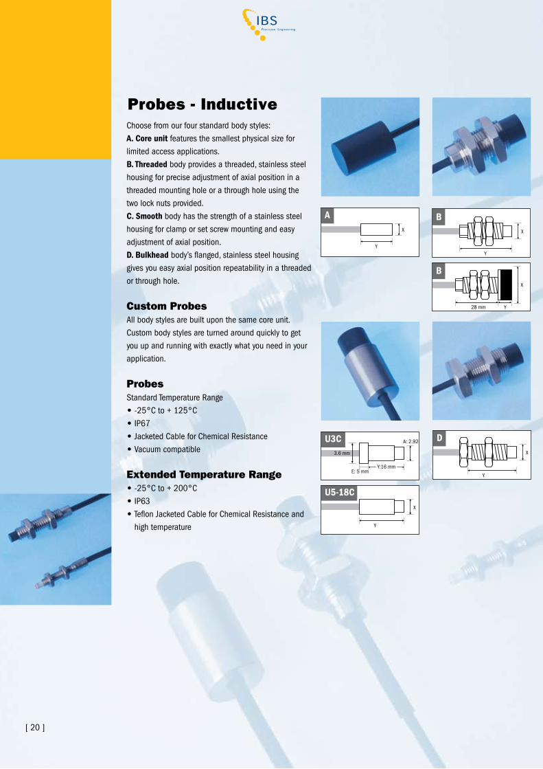
Probes - Inductive
[ 20 ]
Choose from our four standard body styles:A. Core unit features the smallest physical size for limited access applications.B. Threaded body provides a threaded, stainless steel housing for precise adjustment of axial position in a threaded mounting hole or a through hole using the two lock nuts provided.C. Smooth body has the strength of a stainless steel housing for clamp or set screw mounting and easy adjustment of axial position.D. Bulkhead body’s flanged, stainless steel housing gives you easy axial position repeatability in a threaded or through hole.
Custom ProbesAll body styles are built upon the same core unit. Custom body styles are turned around quickly to get you up and running with exactly what you need in your application.
Probes Standard Temperature range• -25°C to + 125°C• IP67• Jacketed Cable for Chemical resistance• vacuum compatible
Extended Temperature Range• -25°C to + 200°C• IP63• Teflon Jacketed Cable for Chemical resistance and high temperature
y
x
A
Y:16 mm
U3C
E: 5 mm
A: 2.92 mm
3.6 mm
Y
X
U5-18C
y
x
D
y
x
B
y28 mm
x
B
U 12 CU UnshieldedEU Extended Temp. Unshielded
5 5mm6 6mm8 8mm12 12mm
A Core UnitB Threaded BodyC Smooth BodyD Flanged BodyX Custom
[ 21 ]
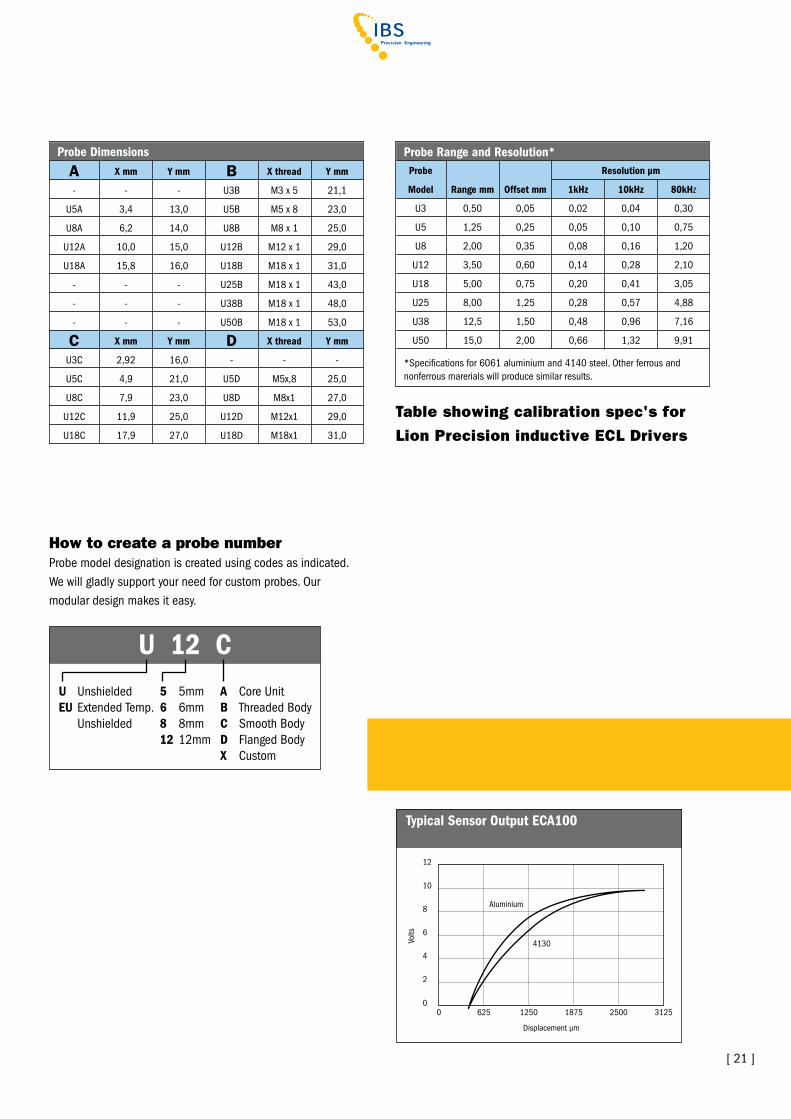
Probe Dimensions A X mm Y mm B X thread Y mm
- - - U3B M3 x 5 21,1
U5A 3,4 13,0 U5B M5 x 8 23,0
U8A 6,2 14,0 U8B M8 x 1 25,0
U12A 10,0 15,0 U12B M12 x 1 29,0
U18A 15,8 16,0 U18B M18 x 1 31,0
- - - U25B M18 x 1 43,0
- - - U38B M18 x 1 48,0
- - - U50B M18 x 1 53,0
C X mm Y mm D X thread Y mm
U3C 2,92 16,0 - - -
U5C 4,9 21,0 U5D M5x,8 25,0
U8C 7,9 23,0 U8D M8x1 27,0
U12C 11,9 25,0 U12D M12x1 29,0
U18C 17,9 27,0 U18D M18x1 31,0
Table showing calibration spec's for
Lion Precision inductive ECL Drivers
Probe Range and Resolution* Probe Resolution µm
Model Range mm Offset mm 1kHz 10kHz 80kHz
U3 0,50 0,05 0,02 0,04 0,30
U5 1,25 0,25 0,05 0,10 0,75
U8 2,00 0,35 0,08 0,16 1,20
U12 3,50 0,60 0,14 0,28 2,10
U18 5,00 0,75 0,20 0,41 3,05
U25 8,00 1,25 0,28 0,57 4,88
U38 12,5 1,50 0,48 0,96 7,16
U50 15,0 2,00 0,66 1,32 9,91
*Specifications for 6061 aluminium and 4140 steel. Other ferrous and nonferrous marerials will produce similar results.
volts
Displacement µm
Aluminium
4130
0
12
10
8
6
4
0
2
3125250018751250625
Typical Sensor Output ECA100
How to create a probe numberProbe model designation is created using codes as indicated. We will gladly support your need for custom probes. Our modular design makes it easy.
[ 22 ]
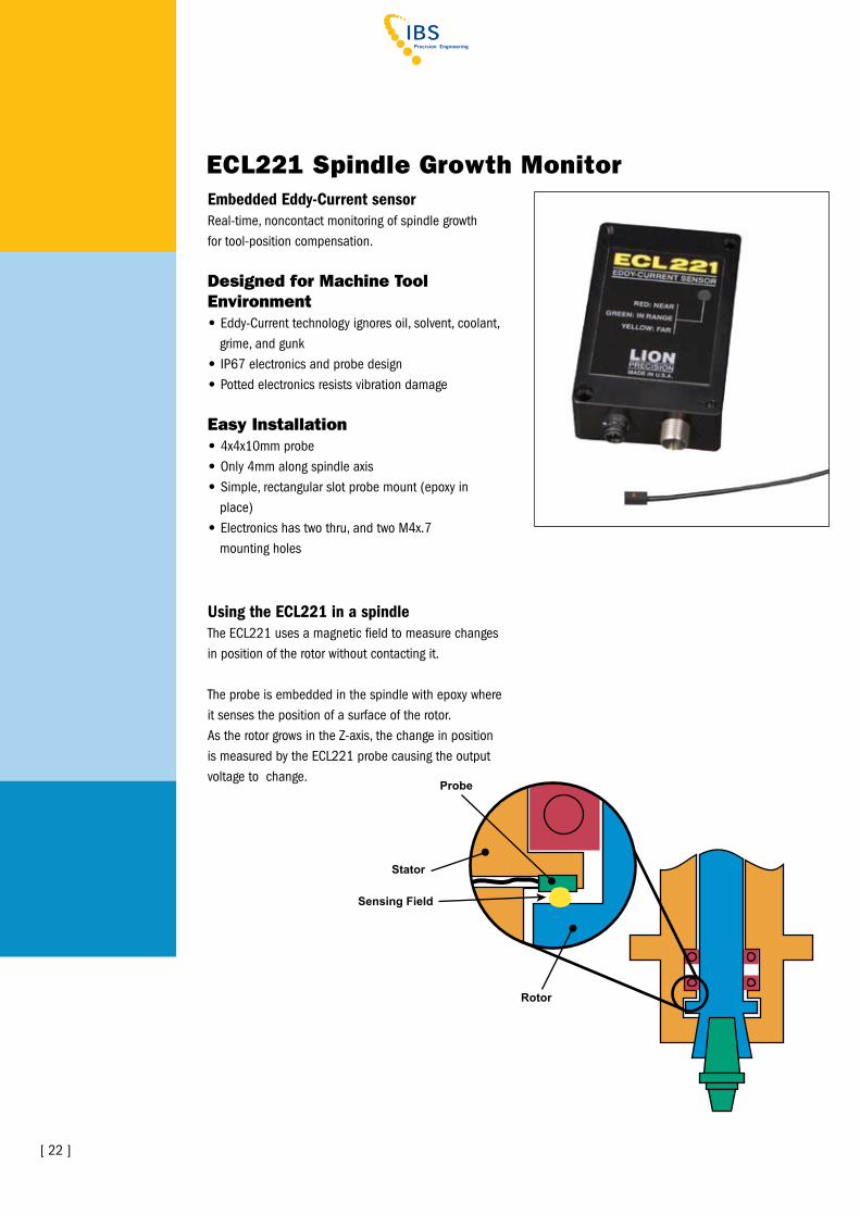
ECL221 Spindle Growth MonitorEmbedded Eddy-Current sensorreal-time, noncontact monitoring of spindle growthfor tool-position compensation.
Designed for Machine Tool Environment• Eddy-Current technology ignores oil, solvent, coolant, grime, and gunk • IP67 electronics and probe design• Potted electronics resists vibration damage
Easy Installation• 4x4x10mm probe • Only 4mm along spindle axis• Simple, rectangular slot probe mount (epoxy in place)• Electronics has two thru, and two M4x.7 mounting holes
Using the ECL221 in a spindleThe ECL221 uses a magnetic field to measure changes in position of the rotor without contacting it.
The probe is embedded in the spindle with epoxy where it senses the position of a surface of the rotor.As the rotor grows in the Z-axis, the change in position is measured by the ECL221 probe causing the output voltage to change.
Sensing Field
Probe
Stator
Rotor
[ 23 ]
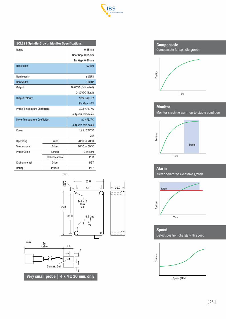
ECL221 Spindle Growth Monitor Specifications:
range 0.35mm
Near Gap: 0.05mm
Far Gap: 0.40mm
resolution 0.4µm
Nonlinearity ±1%FS
Bandwidth 1.0kHz
Output 0-7vDC (Calibrated)
0-10vDC (Total)
Output Polarity Near Gap: 0v
Far Gap: +7v
Probe Temperature Coefficiënt ±0.5%FS/°C
output @ mid-scale
Driver Temperature Coefficiënt ±1%FS/°C
output @ mid-scale
Power 12 to 24vDC
2W
Operating Probe 20°C to 70°C
Temperature: Driver 20°C to 50°C
Probe Cable Length 3 meters
Jacket Material PUr
Environmental Driver IP67
rating Probes IP67
4
mm
49.8
3mcable
Sensing Coil
CompensateCompensate for spindle growth
MonitorMonitor machine warm up to stable condition
AlarmAlert operator to excessive growth
SpeedDetect position change with speed
Very small probe | 4 x 4 x 10 mm. only

At the cutting edge of accuracy
HEADOFFICE | IBS Precision Engineering bvEsp 201, 5633 AD Eindhoven, The Netherlands Telephone: +31 (0)40 290 12 70Fax: +31 (0)40 290 12 79E-mail: [email protected], Internet: www.ibspe.com
IBS Precision Engineering sarl Le Magellan, 7 rue Montespan, 91024 Evry CEDEx, FranceTelephone: +33 (0)1 69 47 60 53Fax: +33 (0)1 69 47 60 70E-mail: [email protected], Internet: www.ibspe.fr
Berührungslose Messungmit kapazitiven undinduktiven Systemen
France | Evry
Netherlands | Eindhoven
Germany | Stuttgart
European Centre of Excellence in Metrology
IBS Precision Engineering Deutschland GmbHLeitzstraße 45, 70469 Stuttgart, GermanyTelephone: +49 (0)711 490 66 230Fax: +49 (0)711 490 66 232E-mail: [email protected], Internet: www.ibspe.de