Nokia Siemens Networks_SURPASS HiT 7035_Technical Description
91
1/91 ON NGM Xie Yijian R. Koster Technical Description SURPASS hiT 7035 June 15, 2010 / Issue 9.0 Copyright 2007 Nokia Siemens Networks. All rights reserved. Technical Description SURPASS hiT 7035 Issue 9.0
Transcript of Nokia Siemens Networks_SURPASS HiT 7035_Technical Description

1/91 ON NGM Xie Yijian R. Koster
Technical Description SURPASS hiT 7035 June 15, 2010 / Issue 9.0
Copyright 2007 Nokia Siemens Networks. All rights reserved.
Technical Description SURPASS hiT 7035 Issue 9.0

2/91 ON NGM Xie Yijian R. Koster
Technical Description SURPASS hiT 7035 June 15, 2010 / Issue 9.0
Copyright 2008 Nokia Siemens Networks. All rights reserved.
The information contained in this document is confidential and the property of Nokia Siemens Networks and is supplied without liability for errors or omissions. It is subject to change without notice and describes only the product defined in the introduction of this documentation. This documentation is intended for the use of Nokia Siemens Networks customers only for the purposes of the agreement under which the document is submitted, and no part of it may be used, reproduced, modified or transmitted in any form or means without the prior written permission of Nokia Siemens Networks. Nokia Siemens Networks welcomes customer comments as part of the process of continuous development and improvement of the documentation.
This Technical Description is provided as a generic descriptive document only. It does not include any legally binding statement. The product features, and details thereof, discussed in this Technical Description may include those that prove to be temporarily or permanently unavailable. Nokia Siemens Networks reserves the right to alter without notice the specification, design, price or conditions of supply of any product or service.
Nokia Siemens Networks will correct errors in this documentation as soon as possible. IN NO EVENT WILL NOKIA SIEMENS NETWORKS BE LIABLE FOR ERRORS IN THIS DOCUMENTATION OR FOR ANY DAMAGES, INCLUDING BUT NOT LIMITED TO SPECIAL, DIRECT, INDIRECT, INCIDENTAL OR CONSEQUENTIAL OR ANY LOSSES, SUCH AS BUT NOT LIMITED TO LOSS OF PROFIT, REVENUE, BUSINESS INTERRUPTION, BUSINESS OPPORTUNITY OR DATA, THAT MAY ARISE FROM THE USE OF THIS DOCUMENT OR THE INFORMATION IN IT.
This documentation and the product it describes are considered protected by copyrights and other intellectual property rights according to the applicable laws.
The wave logo is a trademark of Nokia Siemens Networks Oy. Nokia is a registered trademark of Nokia Corporation. Siemens is a registered trademark of Siemens AG.
Other product names mentioned in this document may be trademarks of their respective owners, and they are mentioned for identification purposes only.
Copyright © Nokia Siemens Networks 2008. All rights reserved. The copyright and the foregoing restrictions on reproduction and use extend to all media in which the information may be embodied.
History of Changes
Control Date Author Comments
3.0 20.06.2007 Rainer Koster Rebranded to NSN layout
4.0 Feb 27, 2008 Th. Jost New SW license structure added
5.0 Jun 05, 2008 Rainer Koster New 4x STM-1 board and enhanced temperature variant added
6.0 Sep 08, 2009 Christoph Schwinghammer
Update with new core
7.0 Sep 15, 2009 Rainer Koster Update of mapping table
8.0 Apr 15, 2010 Xie Yijian Update of port cross connection & VLAN aggregation feature Description of 4x GE card updated Description of DNI function added List of electromagnetic compatibility requirements updated
9.0 Jun 15, 2010 Xie Yijian
Rainer Koster
Modification on description of 4x GE/T card STM-1 I-1 optical interface added modification on max. power consumption update of thermal standard (ETSI Class 3.2 on environment

3/91 ON NGM Xie Yijian R. Koster
Technical Description SURPASS hiT 7035 June 15, 2010 / Issue 9.0
Copyright 2008 Nokia Siemens Networks. All rights reserved.
Contents
1. Introduction ............................................................................ 8
1.1 Editorials ........................................................................................................... 8 1.2 Next Generation SDH ....................................................................................... 8 1.3 SURPASS hiT 70 series ................................................................................... 9
2. SURPASS hiT 7035 Overview............................................. 10
2.1 Overview......................................................................................................... 10 2.1.1 Physical Structure ........................................................................................... 11 2.1.2 Cross Connection and Switching Capability ................................................... 13 2.1.3 Line/Service Interface ..................................................................................... 13
Data Capabilities ............................................................................................................... 14 2.2 Advanced Data Service Support..................................................................... 14 2.2.1 IEEE 802.1Q (VLAN) ...................................................................................... 14 2.2.2 Input Information Rating Limiting .................................................................... 15 2.2.3 Class of Service .............................................................................................. 15 2.2.4 GFP Data Encapsulation ................................................................................ 15 2.2.5 Virtual Concatenation and LCAS .................................................................... 15 2.2.6 RSTP Based Protection .................................................................................. 16 2.2.7 L2 Multicast Function ...................................................................................... 16 2.2.8 Ethernet Transport Schemes .......................................................................... 16
2.3 Network Protections........................................................................................ 17 2.4 Main Features & Strengths ............................................................................. 18 2.4.1 Flexibility ......................................................................................................... 18 2.4.2 Reliability......................................................................................................... 18 2.4.3 Modularity and Scalability ............................................................................... 18 2.4.4 Ease of use ..................................................................................................... 19 2.4.5 Data Handling Capabilities.............................................................................. 19
3. System Application .............................................................. 20
3.1 Networking Capability ..................................................................................... 20 3.1.1 Termination and Multiplexing (TM) ................................................................. 20 3.1.2 Hubbing and Local Cross Connect ................................................................. 21 3.1.3 Linear .............................................................................................................. 22 3.1.4 Ring................................................................................................................. 22 3.1.5 Multiple Ring Closure...................................................................................... 23
3.2 Ethernet Service Applications ......................................................................... 23
4. System Description .............................................................. 24
4.1 Physical Structure and Module Construction .................................................. 24 4.1.1 Chassis Slot Naming....................................................................................... 24 4.1.2 SURPASS hiT 7035 interface options ............................................................ 25
4.2 Power Supply.................................................................................................. 26 4.3 FAN................................................................................................................. 26 4.4 System Controllers (SC, SCE and SCE plus)................................................. 26

4/91 ON NGM Xie Yijian R. Koster
Technical Description SURPASS hiT 7035 June 15, 2010 / Issue 9.0
Copyright 2008 Nokia Siemens Networks. All rights reserved.
4.5 System Interface Panel (SI) ............................................................................ 27 4.6 Cross-Connect Switching (CC) ....................................................................... 27 4.7 SDH Interfaces................................................................................................ 27 4.7.1 1x STM-4 Interface Board............................................................................... 27 4.7.2 2 STM-1 Interface Board............................................................................... 28 4.7.3 4 STM-1 Interface Board............................................................................... 28 4.7.4 2 STM-1E (W/P) Interface............................................................................. 28
4.8 PDH and Data Service Interfaces ................................................................... 29 4.8.1 8x FE/L2 Service Interface Card..................................................................... 29 4.8.2 8x FE/T Service Interface Card....................................................................... 31 4.8.3 1x GE/T Service Interface Board .................................................................... 33 4.8.4 4 GE/T........................................................................................................... 34 4.8.5 3 E3/DS3 (W/P) Interface Card..................................................................... 36 4.8.6 63 E1 (W/P) Interface Card........................................................................... 36
4.9 IMA Interfaces................................................................................................. 37 4.9.1 IMA 126 E1 (W/P) Interface Card ................................................................. 37
4.10 Optical Amplifier.............................................................................................. 37 4.11 User Channel (F1) .......................................................................................... 40 4.12 Engineering Order Wire (EOW) ...................................................................... 40 4.13 Miscellaneous Discrete Input/Output (MDI/MDO)........................................... 41 4.14 Introduction to Software licensing................................................................... 41 4.14.1 General Structure of new SW items................................................................ 42 4.14.2 Software license structure of SURPASS hiT 7035 ......................................... 43
5. Protection and Redundancy................................................. 45
5.1 Network Protection.......................................................................................... 45 5.1.1 MS-SPRing ..................................................................................................... 45 5.1.2 MSP ................................................................................................................ 45 5.1.3 SNCP.............................................................................................................. 46 5.1.4 DNI.................................................................................................................. 46 5.1.5 LCAS............................................................................................................... 47 5.1.6 Ethernet Shared Protection Ring .................................................................... 47 5.1.7 Multiple Layers Protection............................................................................... 47
5.2 Equipment Redundancy and Protection ......................................................... 48 5.2.1 Redundant Power Supply ............................................................................... 48 5.2.2 Redundant Cross-Connect ............................................................................. 48 5.2.3 Electrical Interface Module Protection ............................................................ 48 5.2.4 Protection under Abnormal Condition ............................................................. 48 5.2.5 Software Fault Tolerance................................................................................ 49 5.2.6 Data Security .................................................................................................. 49
6. Technical Specification ........................................................ 50
6.1 Multiplexing Structure ..................................................................................... 50 6.2 SDH Overhead................................................................................................ 52 6.3 Interface Types ............................................................................................... 53 6.3.1 Electrical Interfaces......................................................................................... 54 6.3.2 Optical Interfaces ............................................................................................ 54 6.3.3 Management and Maintenance Interface ....................................................... 56
5/91 ON NGM Xie Yijian R. Koster
Technical Description SURPASS hiT 7035 June 15, 2010 / Issue 9.0
Copyright 2008 Nokia Siemens Networks. All rights reserved.
6.4 Interface Performance Specifications ............................................................. 56 6.4.1 Optical Interface Performances ...................................................................... 56 6.4.2 STM-1 Optical Interface Performance ............................................................ 57 6.4.3 STM-4 Optical Interface Performance ............................................................ 58 6.4.4 STM-16 Optical Interface Performance .......................................................... 59 6.4.5 Multi-rate CWDM interface Optical Performance............................................ 60 6.4.6 2.5G DWDM interface Optical Performance ................................................... 61 6.4.7 GE Optical Transmitter and Receiver Interfaces ............................................ 63 6.4.8 Electrical Interface Performances ................................................................... 65 6.4.9 Timing and Synchronization Performance ...................................................... 67 6.4.10 Jitter Performance........................................................................................... 67 6.4.11 STM-N Interface Output Jitter ......................................................................... 67
6.5 Timing ............................................................................................................. 70 6.6 Power Source ................................................................................................. 70 6.6.1 Power Supply.................................................................................................. 70 6.6.2 Power Consumption........................................................................................ 71 6.6.3 Cooling............................................................................................................ 71 6.6.4 Mechanical Structure ...................................................................................... 71
6.7 Environment Requirements ............................................................................ 71 6.7.1 Enhanced Temperature Variant...................................................................... 72
6.8 Electromagnetic Compatibility......................................................................... 72 6.9 Vibration Tests ................................................................................................ 74 6.9.1 Shipping Test .................................................................................................. 74 6.9.2 Office Test....................................................................................................... 74
6.10 Alarms and Events.......................................................................................... 75 6.10.1 Alarm Types.................................................................................................... 75 6.10.2 Alarm Severity Level ....................................................................................... 75 6.10.3 Alarm Reports ................................................................................................. 75 6.10.4 Events ............................................................................................................. 76
7. Standard Compliance .......................................................... 79
8. Appendix 1: Definitions and Abbreviations .......................... 81
9. Appendix 2: Basis Technologies.......................................... 85
9.1 Generic Framing Procedure (GFP)................................................................. 85 9.2 Virtual Concatenation (VCat) .......................................................................... 87 9.3 Link Capacity Adjustment Scheme (LCAS) .................................................... 88 9.4 Ethernet Functions and Services .................................................................... 88
10. Appendix 3: Related Documents ......................................... 91

6/91 ON NGM Xie Yijian R. Koster
Technical Description SURPASS hiT 7035 June 15, 2010 / Issue 9.0
Copyright 2008 Nokia Siemens Networks. All rights reserved.
List of Figures Figure 1 - Future Traffic Growth.................................................................................................... 8
Figure 2 - SURPASS hiT 7035 chassis ......................................................................................10
Figure 3 – SURPASS hiT 7035 Physical Structure.....................................................................12
Figure 4 - Three Ethernet data transmission methods in SURPASS hiT 7035 ring ...................17
Figure 5 - SURPASS hiT 7035 termination and multiplexing capability .....................................20
Figure 6 - SURPASS hiT 7035 termination and multiplexing capability .....................................21
Figure 7 - SURPASS hiT 7035 linear network configuration ......................................................22
Figure 8 - SURPASS hiT 7035 2-fiber MS-SPRing application ..................................................22
Figure 9 - Multiple Ring closure at a single SURPASS hiT 7035 node ...................................... 23
Figure 10 - SURPASS hiT 7035 Chassis view ...........................................................................24
Figure 11 - SURPASS hiT 7035 chassis slot naming.................................................................25
Figure 12 - SURPASS hiT 7035 Cards List ................................................................................26
Figure 13 - Functional block diagram of 2 STM-1E (W/P) card protection ...............................29
Figure 14 - 8 FE/L2 card functional block diagram ...................................................................30
Figure 15 - 8 FE/L2 interface card external interfaces..............................................................31
Figure 16 - 8 FE/L2 card LEDs .................................................................................................31
Figure 17 - 8 FE/T card functional block diagram.....................................................................32
Figure 18 - 8 FE/T interface card external interfaces................................................................ 32
Figure 19 - 8 FE/T card LEDs ...................................................................................................33
Figure 20 - 1 GE/T service board module functional block diagram.........................................33
Figure 21 - Functional block diagram of 3 E3/DS3 (W/P) card protection................................36
Figure 22 –Functional block diagram of IMA (W/P) card protection ...........................................37
Figure 23 – OA module functional building block diagram .........................................................38
Figure 24 – OA module safty procedure .....................................................................................40
Figure 25 – OA card external interfaces .....................................................................................40
Figure 26 – OA card LEDs .......................................................................................................... 40
Figure 27 – External XOW box ...................................................................................................41
Figure 28: Software license structure in Next Generation Metro ................................................42
Figure 29: Software license structure of SURPASS hiT 7035 ....................................................44
Figure 30: Software license structure of SURPASS hiT 7035 – E1 Extension shelf ..................45
Figure 31 - Cross-Connect Multiplexing Structure (ITU-T G.707) .............................................. 50
Figure 32 - Terminated Mapping Structure .................................................................................51
Figure 33 - Payload Mapping ...................................................................................................... 51
Figure 34 – SURPASS hiT 7035 supported SDH overhead process .........................................53
Figure 35 – SURPASS hiT 7035 Interface Types.......................................................................53

7/91 ON NGM Xie Yijian R. Koster
Technical Description SURPASS hiT 7035 June 15, 2010 / Issue 9.0
Copyright 2008 Nokia Siemens Networks. All rights reserved.
Figure 36 - SURPASS hiT 7035 optical service interfaces supported........................................55
Figure 37 - STM-N Optical Interface Parameters and Application Codes ..................................56
Figure 38 - SURPASS hiT 7035 STM-1 Optical Interface Specifications ...................................57
Figure 39 - SURPASS hiT 7035 STM-4 Optical Interface Specifications ...................................59
Figure 40 - SURPASS hiT 7035 STM-16 Optical Interface Specifications.................................59
Figure 41 - SURPASS hiT 7035 CWDM Optical Interface Specifications ..................................61
Figure 42 - SURPASS hiT 7035 DWDM Optical Interface Specifications ..................................62
Figure 43 - SURPASS hiT 7035 DWDM Wavelenthes...............................................................62
Figure 44 - 1000 Base-SX transmitter interface parameters ......................................................63
Figure 45 - 1000 Base-SX receiving interface parameters.........................................................64
Figure 46 - 1000 Base-LX Transmitter interface parameters .....................................................64
Figure 47 - 1000 Base-LX receiver interface parameters...........................................................64
Figure 48 - 2048 kbit/s Electrical Interface Parameters..............................................................65
Figure 49 - Electrical Interface Output Signals Bit Rate Allowable Deviation............................. 66
Figure 50 - Electrical Interface Allowable Input Attenuation .......................................................66
Figure 51 - Electrical Interface Allowable Input Port Frequency Deviation................................. 66
Figure 52 - Electrical Interface Input Port Anti-interference Capability .......................................67
Figure 53 - Timing Output Jitter .................................................................................................. 67
Figure 54 - Internal Timing Source Output Frequency ...............................................................67
Figure 55 - STM-1/-4/-16 Interface Output Jitter.........................................................................68
Figure 56 - STM-1 Interface Jitter Tolerance ..............................................................................68
Figure 57 - STM-4 Interface Jitter Tolerance ..............................................................................69
Figure 58 - STM-16 Interface Jitter Tolerance ............................................................................69
Figure 59 - PDH mapping jitter generation specification ............................................................69
Figure 60 - SURPASS hiT 7035 PDH interface combined jitter generation spec....................... 70
Figure 61 - SURPASS hiT 7035 Environment Requirements.....................................................72
Figure 62 - SURPASS hiT 7035 Electromagnetic Compatibility RequirementsFehler! Textmarke nicht definiert.
Figure 63 - Shipping Test Standards ..........................................................................................74
Figure 64 - Office test standards................................................................................................. 75
Figure 65 - Management Events.................................................................................................76
Figure 66 - Hardware Events ...................................................................................................... 77
Figure 67 - Software Events........................................................................................................ 78
Figure 68 - GFP mapping............................................................................................................ 86
Figure 69 - Comparison between GFP and PPP........................................................................87
Figure 70 – Port Cross Connection.............................................................................................89
Figure 71 – Port+VLAN Cross Connection .................................................................................90

8/91 ON NGM Xie Yijian R. Koster
Technical Description SURPASS hiT 7035 June 15, 2010 / Issue 9.0
Copyright 2008 Nokia Siemens Networks. All rights reserved.
1. Introduction
1.1 Editorials
This document is a technical description for the product SURPASS hiT 7035. The technical descriptions of other products of the SURPASS hiT 70 series are also available. This document is not a marketing document. The target of this document is to inform on detail about the product, product features and the application in the network environment.
It is not a document for advertisement purposes but it is useful to inform our customer in detail in the after sales period. For marketing and advertisement related product information please contact the sales department.
If the reader is looking for information on the basis technologies please refer to 9 Appendix 2: Basis Technologies.
1.2 Next Generation SDH For almost two decades, Synchronous Digital Hierarchy (SDH) has been the preferred transport technology over optical fibers. SDH is the dominant transport protocol in virtually all long-haul networks (voice and data) as well as in metro networks that were originally developed for voice traffic. As a resilient, well-understood transport mechanism, SDH has stood the test of time. Its reliability is unsurpassed. The ability of SDH to support 50-msec switching to backup paths, combined with extensive performance monitoring features for carrier-class transport.
Legacy SDH was designed mainly to transport circuit oriented services like voice and as such is an inherently rigid and inefficient method for transporting data. Traditionally a single wire speed Gigabit Ethernet service (1.25G) will be allocated to one STM-16 channel (2.5G). This means 48 % of the of this STM-16 pipe remains as idle capacity.
Figure 1 - Future Traffic Growth
1
10
100
1000
10000
2000 2002 2004 2006 2008 2010
Tbit/s Phone
Internet
Intranet WAN
Source: NSN

9/91 ON NGM Xie Yijian R. Koster
Technical Description SURPASS hiT 7035 June 15, 2010 / Issue 9.0
Copyright 2008 Nokia Siemens Networks. All rights reserved.
The phenomenal growth in bandwidth, connectivity and content generated by the Internet, Intranet and broadband applications, has made native data transfer a very important criteria for telecommunication infrastructure (see Figure 1). Ethernet has become the de facto standard for enterprise networks. In Storage Area Networks (SAN), ESCONTM, FICONTM and Fiber Channel are by far today‘s most dominating technology as well.
The solution is Next Generation SDH—technology that transforms rigid, circuit-oriented SDH networks to a universal transport mechanism that is optimized for both voice and data. The technology enables carriers to keep up with growing demands for bandwidth, to efficiently carry both streaming and bursty traffic, and adapt to constantly changing traffic patterns. Multiple protocols and thus services are supported: from basic TDM voice, Ethernet, as well as SAN.
1.3 SURPASS hiT 70 series
Siemens has introduced a new range of equipment that makes the promise of Next Generation SDH a reality: the SURPASS hiT 70 series. This platform provides the flexibility of true packet switching and Ethernet transport, while operating with the inherent reliability of SDH. Multiple network elements are integrated and consolidated into a single compact unit. The efficiency of this approach, together with extensive use of highly integrated components allows the SURPASS hiT 70 series to be offered at lower costs than current solutions.
Data + Voice = SURPASS hiT 70 series
In order to address the varying needs and requirements of carrier‘s carrier, carrier and enterprise, the SURPASS hiT 70 series consists of a diverse range of products, namely:
SURPASS hiT 7080 ADM / CC multiple STM-64
SURPASS hiT 7070 SC/DC ADM / CC, multiple STM-64
SURPASS hiT 7065 ADM / CC, multiple STM-64
SURPASS hiT 7060 HC ADM 64, multiple STM-16
SURPASS hiT 7060 ADM, multiple STM-16
SURPASS hiT 7035 ADM 16/4/1, multiple STM 4 upgradeable to
multiple STM16
SURPASS hiT 7030 ADM 4/1 modular
SURPASS hiT 7025 ADM 16/4/1, multiple STM 4 upgradeable to
multiple STM16
SURPASS hiT 7020 ADM 4/1 single board CPE

10/91 ON NGM Xie Yijian R. Koster
Technical Description SURPASS hiT 7035 June 15, 2010 / Issue 9.0
Copyright 2008 Nokia Siemens Networks. All rights reserved.
This Technical Description covers SURPASS hiT 7035, only. For detailed description of the other product please refer to 10 Appendix 3: Related Documents.
2. SURPASS hiT 7035 Overview
2.1 Overview
SURPASS hiT 7035 is a compact carrier class full blown STM-4/-1 add-drop-multiplexer which can be upgraded to a compact STM-16 ADM.
SURPASS hiT 7035 supports core equipment protection with no single point of failure, and PDH electrical protection.
It offers rich Ethernet features.
Applications:
Optimized for SDH applications with data capabilities
In transmission networks of mobile network
Central office STM-16/-4/-1 add drop multiplexer
High-end enterprise services SURPASS hiT 7035 offers a High Order cross connection capacity up to 32.8G and a Low Order cross connection capacity up to 5G.
Figure 2 - SURPASS hiT 7035 chassis

11/91 ON NGM Xie Yijian R. Koster
Technical Description SURPASS hiT 7035 June 15, 2010 / Issue 9.0
Copyright 2008 Nokia Siemens Networks. All rights reserved.
Surpass hiT 7035 offers a powerful and cost-effective product design for PDH, SDH and data applications independent if these applications capabilities are requested for use in central offices, fixed part of mobile networks or in combination with high-end enterprise services.
SURPASS hiT 7035 supports the complete range of PDH and SDH interfaces ranging from E1, E3/DS3, STM-1 el./opt. to STM-4 and even STM-16. It provides a full suite of SDH functions including mapping, multiplexing, cross-connection and various protection schemes.
SURPASS hiT 7035 has a modular and scalable design, enabling a pay-as-you-grow deployment plan. The system can be initially deployed as a low cost, modest capacity system, and then enlarged to a high capacity, multi-service system. A large variety of service modules ensure a cost-effective match with service demands of today while retaining superior flexibility to meet future service requirements.
Its advance software architecture design results in a highly fault-tolerant system. Combined with built-in hardware redundancies, SURPASS hiT 7035 achieves carrier-class reliability with 99.999% availability.
The system is fully compliant with ITU-T and/or IEEE standards, and is inter-operable with other standards-based SDH, multi-service transport, and data communication products.
Utilizing SURPASS hiT 7035 in combination with the multi-service capabilities of Siemens TNMS network management system, service providers can cost-effectively grow their embedded base networks or launch new networks
2.1.1 Physical Structure
The physical dimensions of SURPASS hiT 7035 chassis are 403mm (wide) 486mm (high) 240mm (deep) (300mm back to door), which is compliant to 19 and 21 inch industry standards.

12/91 ON NGM Xie Yijian R. Koster
Technical Description SURPASS hiT 7035 June 15, 2010 / Issue 9.0
Copyright 2008 Nokia Siemens Networks. All rights reserved.
Figure 3 – SURPASS hiT 7035 Physical Structure
The dimension of physical cards is:
Long cards, SC = 253 mm x 264 mm x 30 mm
Short cards, PWR = 238 mm x130 mm x 30 mm
Long IO (1-4) = 229mm x 329mm x 33 mm
SI, Short IO (5-7) = 198 mm x 130 mm x 33 mm
FAN = 225 mm x 245 mm x 52 mm
All external interfaces have front access.
LC2
LC4
LC3
CC w/ STM-16/4/1
CC w/ STM-16/4/1
LC5
F
A
IO 4 IO 1 IO 2 IO 3 SCE
SI IO5 IO7 LC8
LC7
LC10
LC9
IO6 LC11
LC1
LC6
PWR
PWR

13/91 ON NGM Xie Yijian R. Koster
Technical Description SURPASS hiT 7035 June 15, 2010 / Issue 9.0
Copyright 2008 Nokia Siemens Networks. All rights reserved.
2.1.2 Cross Connection and Switching Capability
SURPASS hiT 7035 supports three types of cross connection and switching capabilities:
ADM-4/-1: 7.2G/2.5G CC with 1x STM-4/-1 line interface:
HOCC: (7.2G)
LOCC: (2.5G)
ADM-16/-4: 15.2G/5 CC with 1x STM-16/-4 line interface:
HOCC: 15.2G
LOCC: 5G
ADM-16/-4/-1: 33G/10 CC with 2x STM-16/-4 or 1*STM-16+4*STM4/1 line interface:
HOCC: 33G
LOCC:10G
2.1.3 Line/Service Interface
SURPASS hiT 7035 provides the following line interfaces:
1. SDH: 1 STM-4 Optical Line Interface Board
2. SDH: 2 STM-1 Optical Interface Board
3. SDH: 2 STM-1E (W/P) Electrical Interface Card
4. SDH: 2 STM-1E PaddleCard
5. PDH: 3 E3/DS3 (W/P) interface card
6. PDH: 3 E3/DS3 Paddle
7. PDH: 63 E1 (W/P) client interface card
8. PDH: 63 E1 75ohm Paddle
9. PDH: 63 E1 120ohm Paddle
10. ATM-IMA 126xE1 interface card
11. IP/Ethernet: 8 FE/L2 interface card
12. IP/Ethernet: 8 FE/T Ethernet interface card
13. IP/Ethernet: 1 GE/T interface card
14. 4xGE/T interface card
14/91 ON NGM Xie Yijian R. Koster
Technical Description SURPASS hiT 7035 June 15, 2010 / Issue 9.0
Copyright 2008 Nokia Siemens Networks. All rights reserved.
15. Optical Amplifier cards (13, 15 and 18 dBm)
16. Optical Pre-Amplifier card (20dB)
Data Capabilities
SURPASS hiT 7035 supports GFP (ITU-T G.7041 / Y.1303) encapsulation for Ethernet data.
SURPASS hiT 7035 supports VC-12-nv, VC-3-nv and VC-4-nv virtual concatenation (ITU-T G.707 / Y.1322) efficiently mapping data traffic into SDH payload. SURPASS hiT 7035 also supports LCAS (G.7042) at VC-12-nv, VC-3-nv and VC-4-nv level, which provides dynamic bandwidth adjustment.
SURPASS hiT 7035 provides SDH network protection functions including Multiplex Section Shared Protection Ring, Multiplex Section Protection 1 + 1 unidirectional/bi-directional, and Sub-Network Connection Protection (SNCP) at VC-12/-3/-4 levels.
2.2 Advanced Data Service Support
SURPASS hiT 7035 supports the following Layer 2 data functions:
1) IEEE 802.1Q (VLAN)
2) Input information limiting
3) Class of Service
4) GFP
5) VCAT and LCAS
6) RSTP
7) Layer 2 multicast
8) ESR
2.2.1 IEEE 802.1Q (VLAN)
SURPASS hiT 7035 supports Ethernet switching function, which is in compliance with IEEE Standard 802.1Q. SURPASS hiT 7035 supports VLAN on a per port basis. Each data port can be enabled or disabled for VLAN function.
At the ingress, each port can be set either to accept both VLAN-tagged and untagged frames, or to accept only the VLAN-tagged frames depending on the application requirements. At the egress, each port can be set to remove the VLAN tags or keep the VLAN tags. It is also possible to assign each port a PVID (Port-based VLAN ID), which will be inserted to the untagged frames as a VLAN ID when the frames come into the port. In addition, each port can be put into one or more VLANs by assigning a VLAN list to it, allowing different customers or different applications to share the same port. All

15/91 ON NGM Xie Yijian R. Koster
Technical Description SURPASS hiT 7035 June 15, 2010 / Issue 9.0
Copyright 2008 Nokia Siemens Networks. All rights reserved.
services within the specific VLAN in the list can dynamically share the bandwidth of the port and still retain security. If the port belongs to a VLAN, the frames of that VLAN will be able to pass-through the port; otherwise the frames will be discarded.
Optionally, each port can be set to transparent mode, meaning that no switching functions will be performed on the frames. In this case, the pairing of one LAN (customer) port and one WAN (internal uplink) port must be established.
2.2.2 Input Information Rating Limiting
SURPASS hiT 7035 supports Input Rate Limiting function on a port basis or a VLAN basis.
An input information rate-limiting feature allows the one to control the maximum bandwidth an end user can obtain from the network. The minimum rate is 128 Kbit/s, and the bandwidth incremental granularity is as low as 128 Kbit/s.
2.2.3 Class of Service
SURPASS hiT 7035 supports 802.1p CoS at a port basis or a VLAN basis.
At the ingress of every port, there is a buffer to accommodate the input burst when the output port is congested. The memory for buffering is shared among all ports on a card, and the total capacity is up to 16 Mbytes. At the egress of every port, there are four queues, which can be assigned with different priorities or weights. The scheduling scheme can be set either to strict policing or Weighted Round-Robin.
2.2.4 GFP Data Encapsulation
SURPASS hiT 7035 incorporates advanced Generic Framing Procedure (GFP) (G.7041 / Y.1303) mapping scheme to encapsulate Ethernet traffic into SDH payloads. GFP encapsulated data is then mapped into SDH payloads using Virtual Concatenation techniques of ITU-T standard G.707/Y.1322. This process provides the most efficient mapping of the packets and the greatest bandwidth
2.2.5 Virtual Concatenation and LCAS
SURPASS hiT 7035 supports VC-12-nv, VC-3-nv and VC-4-nv. The VC provides fine-tuned SDH pipes to match the needs of packet – and to boost carriers’ traffic-handling scalability and efficiency. The system can accommodate up to 48ms (for all transparent cards) or 32 ms (for FE/L2 card) delay deference between the fastest VC-4 member and the slowest VC-4 member and accommodate 16 ms delay deference between the fastest VC-12 member and the slowest VC-12 member.
16/91 ON NGM Xie Yijian R. Koster
Technical Description SURPASS hiT 7035 June 15, 2010 / Issue 9.0
Copyright 2008 Nokia Siemens Networks. All rights reserved.
SURPASS hiT 7035 supports LCAS. The combination of VCAT and LCAS provide soft protection schemes. LCAS provides dynamic adjustment of the size of a virtually concatenated group of channels.
2.2.6 RSTP Based Protection
The Rapid Spanning Tree protocol acc. IEEE 802.1w and MSTP acc. IEEE 802.1s prevent against loops at the WAN side of the network while providing L2 protection.
2.2.7 L2 Multicast Function
SURPASS hiT 7035 supports Layer 2 multicast functionality including pre-provisioned static multicast, or IGMP Snooping controlled dynamic multicast.
2.2.8 Ethernet Transport Schemes
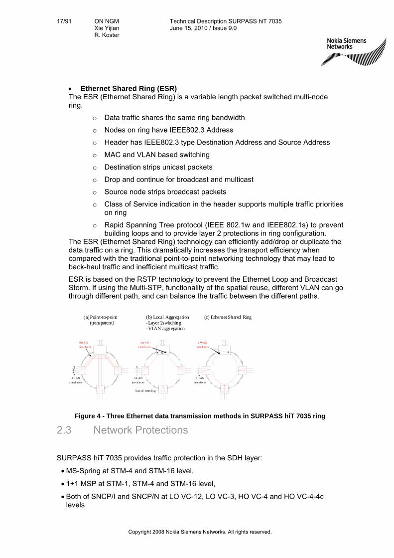
SURPASS hiT 7035 supports three Ethernet data transport schemes, which are described below:
Point-to-point transparent: In this mechanism, dedicated bandwidth is assigned to end-to-end traffic. The Virtual Concatenation technique is used in the SURPASS hiT products to provide more efficient bandwidth assignment. This scheme is more suitable for high security requirements and delay-sensitive traffic as each traffic has a dedicated bandwidth. The drawback is the limited bandwidth efficiency. As we know, Ethernet traffic has bursty characteristics and is delay insensitive. Statistical multiplexing is usually employed in data network to achieve bandwidth efficiency. Dedicated bandwidth per data flow is not efficient for bursty traffic transmission.
Layer 2 aggregation In this mechanism, the Ethernet switching and aggregation is performed at the NE to allow local user traffic to be aggregated into a higher rate SDH trunk. The statistical multiplexing of multiple Ethernet traffic makes the bandwidth utilization more efficient.
Port Cross Connection That means the frame from ingress port (both WAN or LAN) will be forward to egress port (both WAN or LAN) according to the ingress port. At the ingress port a forward table is configured by operator to define the egress port base on the ingress port
Port + VLAN Cross Connection (VLAN aggregation ) That means the frame from ingress port from ingress port (both WAN or LAN) will be forward to egress port (both WAN or LAN) according to its VLAN tag. At the ingress port a forward table is configured by operator to define the egress port based on VLAN. Untagged frame will be discarded.
17/91 ON NGM Xie Yijian R. Koster
Technical Description SURPASS hiT 7035 June 15, 2010 / Issue 9.0
Copyright 2008 Nokia Siemens Networks. All rights reserved.
Ethernet Shared Ring (ESR) The ESR (Ethernet Shared Ring) is a variable length packet switched multi-node ring.
o Data traffic shares the same ring bandwidth
o Nodes on ring have IEEE802.3 Address
o Header has IEEE802.3 type Destination Address and Source Address
o MAC and VLAN based switching
o Destination strips unicast packets
o Drop and continue for broadcast and multicast
o Source node strips broadcast packets
o Class of Service indication in the header supports multiple traffic priorities on ring
o Rapid Spanning Tree protocol (IEEE 802.1w and IEEE802.1s) to prevent building loops and to provide layer 2 protections in ring configuration.
The ESR (Ethernet Shared Ring) technology can efficiently add/drop or duplicate the data traffic on a ring. This dramatically increases the transport efficiency when compared with the traditional point-to-point networking technology that may lead to back-haul traffic and inefficient multicast traffic.
ESR is based on the RSTP technology to prevent the Ethernet Loop and Broadcast Storm. If using the Multi-STP, functionality of the spatial reuse, different VLAN can go through different path, and can balance the traffic between the different paths.
(c) Ethernet Shared Ring(a) Point-to-point(transparent)
(b) Local Aggregation-Layer 2switching-VLAN aggregation
3WAN
i nterf aces
9WAN
Inter faces
3 L AN
int erf aces
2 WAN
in terf aces
3 L AN
i nterf aces
3 LAN
inte rfaces
Loc al muxing
Figure 4 - Three Ethernet data transmission methods in SURPASS hiT 7035 ring
2.3 Network Protections
SURPASS hiT 7035 provides traffic protection in the SDH layer:
MS-Spring at STM-4 and STM-16 level,
1+1 MSP at STM-1, STM-4 and STM-16 level,
Both of SNCP/I and SNCP/N at LO VC-12, LO VC-3, HO VC-4 and HO VC-4-4c levels

18/91 ON NGM Xie Yijian R. Koster
Technical Description SURPASS hiT 7035 June 15, 2010 / Issue 9.0
Copyright 2008 Nokia Siemens Networks. All rights reserved.
DNI at STM-4 and STM-16 level
SURPASS hiT 7025 also provides traffic protection in the Ethernet layer:
LCAS soft protection (Diverses routing),
Link aggregation at LAN and WAN side.
2.4 Main Features & Strengths
2.4.1 Flexibility
The hiT 7035 offers the flexibility to be used as full blown ADM-1/ ADM-4 to compact ADM-16.
Interconnection to your SDH network can be at STM-16, STM-4 or STM-1 level.
For reach of very long and ultra long distance applications without use of intermediated regenerators optical booster and preamplifiers are offered. Maximum distances up to 160 km (in compliance with ITU-T Recommendation G.692 U-16.2/3) can be achieved.
2.4.2 Reliability
SURPASS hiT 7035 is due to its full redundancy concept a very reliable product:
The system is based on the standardized SDH technology, which is a market proven networking technology.
Highly integrated components guarantee for highest system reliability:
Optical transmission can be protected using Multiplex Section Shared Protection Ring, Sub-Network Connection Protection (SNCP), and Multiplex Section Protection 1+1 unidirectional / bidirectional.
Thermal Sensor detects if the internal temperature exceeds the threshold and raise the over temperature alarm.
2.4.3 Modularity and Scalability
SURPASS hiT 7035 is of modular design and allows therefore a high configuration versatility.
All optical line interfaces uses SFP optical modules. This modularity reduces the spare part stock and increases the flexibility of the system as on the same card different types of SFP modules can be used on different ports (e.g. short haul and long haul).
19/91 ON NGM Xie Yijian R. Koster
Technical Description SURPASS hiT 7035 June 15, 2010 / Issue 9.0
Copyright 2008 Nokia Siemens Networks. All rights reserved.
The scalability from full blow ADM-1/ ADM-4 to compact ADM-16 allows for flexible growth with evolving networking needs.
SURPASS hiT 7035 offers the ability to interface with all NSN and other vendor’s optical networking systems.
The same applies for data processing equipment as the equipment offers standardized Ethernet interfaces (10/100 BaseT, 100 Base FX, FC1G or 2G and Gigabit Ethernet).
2.4.4 Ease of use
All optical and electrical interfaces have front access.
Support for Small Form-factor Pluggable (SFP) optical interfaces for STM-16, STM-4, STM-1, 100Base FX, FC1G or 2G, and GE SFP optical interfaces, allow convenient field replacement of the optical interfaces. As the network evolves, different optical modules can be inserted to meet the changing network environment and growth.
Additional, state-of-art electrical SFP module is supported for STM-1 interface card and GE card.
2.4.5 Data Handling Capabilities
Support for 4094 VLANs per L2 switch card in order to transport end-user data securely with a variety of Class-of-Service options that allow differentiated services between users or between applications with a given user.
Ethernet traffic is encapsulated into SDH using either GFP. This provides the most advanced and efficient way to carry data traffic within a SDH network.
Virtual Concatenation is used to provide scalable, efficient, compatible, and resilient use of SDH to move traffic. This greatly increases the useable bandwidth of the network.

20/91 ON NGM Xie Yijian R. Koster
Technical Description SURPASS hiT 7035 June 15, 2010 / Issue 9.0
Copyright 2008 Nokia Siemens Networks. All rights reserved.
3. System Application SURPASS hiT 7035 multi-service access platform is a highly flexible product capable of supporting a variety of network applications like bandwidth access, service-on-demand and LAN services.
SURPASS hiT 7035 can be configured in such a way that it supports a large variety of network applications with any mix of PDH, SDH and Ethernet services.
3.1 Networking Capability
SURPASS hiT 7035 provides high flexibility and compactness supporting a large variety of configurations for STM-16, STM-4 and STM-1 network applications:
Termination and multiplexing
Small local cross connect
Linear
Ring
Multi Ring closure
3.1.1 Termination and Multiplexing (TM)
SURPASS hiT 7035 system can be configured to function as a hub-Terminal at STM-16, STM-4 or STM-1 level
Figure 5 - SURPASS hiT 7035 termination and multiplexing capability
SURPASS
hiT 7035 STM-1/-4/16
E1
E3/DS3
10/100M
10/100/1000M
100M FX
GE
STM-1E
STM-1/4
ATM IMA
FC

21/91 ON NGM Xie Yijian R. Koster
Technical Description SURPASS hiT 7035 June 15, 2010 / Issue 9.0
Copyright 2008 Nokia Siemens Networks. All rights reserved.
3.1.2 Hubbing and Local Cross Connect
SURPASS hiT 7035 system can be used to function as a small local cross-connect system (or can be applied in hubbing configurations). This allows various hybrid network architectures with a variety of connection speeds and network topologies such as rings, multi-rings, subtending rings, or linear structures. This eliminates the need for back-to-back terminals and greatly increases network flexibility.
SURPASS hiT 7035 can serve a cluster of other terminals, for example SURPASS hiT 7030 or other vendor’s products that have standard SDH interfaces, located at remote sites, through point-to-point connections with optional 1+1 MSP protection. It also serves as an aggregation Hub for Subtending Rings. This feature eliminates back-to-back terminals that would be required to serve multi-ring connections using equipment with less ring-closure capabilities.
+
Figure 6 - SURPASS hiT 7035 termination and multiplexing capability
SURPASS
hiT 7035 STM-1/-4/16 STM-1/-4/16
E1
E3/DS3
100/100M
10/100/1000M
100M FX
GE
STM-1E
STM-1/4
ATM IMA
FC

22/91 ON NGM Xie Yijian R. Koster
Technical Description SURPASS hiT 7035 June 15, 2010 / Issue 9.0
Copyright 2008 Nokia Siemens Networks. All rights reserved.
3.1.3 Linear
SURPASS hiT 7035 supports STM-16/-4/-1 linear network topology as depicted in figure below:
Figure 7 - SURPASS hiT 7035 linear network configuration
3.1.4 Ring
Rings provide redundant bandwidth and/or equipment to ensure system integrity in the event of any transmission or timing failure, including a fiber cut or node failure. A ring is a collection of nodes that form a closed loop, in which each node is connected to adjacent nodes.
SURPASS hiT 7035 supports two-fiber MS-SPRing. Figure below shows a SURPASS hiT 7035 ring example.
Figure 8 - SURPASS hiT 7035 2-fiber MS-SPRing application
When using the MS-SPRing protection mechanism, rings ranging from 3 to 16 nodes are supported (the maximum of 16 nodes in a ring is specified in G.841). They perform automatic protection switching (revertive) in less than 50 milliseconds.
2-Fiber STM-4/16 ring
hiT7035
hiT7035 hiT7035
hiT7035
hiT7035 TM
hiT7035 ADM
hiT7035 TM

23/91 ON NGM Xie Yijian R. Koster
Technical Description SURPASS hiT 7035 June 15, 2010 / Issue 9.0
Copyright 2008 Nokia Siemens Networks. All rights reserved.
3.1.5 Multiple Ring Closure
A single network element as depicted in Figure 9 can interconnect two SURPASS hiT 7035 rings working at different or the same line speeds.
Figure 9 - Multiple Ring closure at a single SURPASS hiT 7035 node
3.2 Ethernet Service Applications
SURPASS hiT 7035 provides data transport over SDH, and offers various data applications in addition to traditional TDM applications. This offers service providers a cost-effective, simple, and reliable multi-service solution for their customers.
SURPASS hiT 7035 can provide aggregation from any port to any port, and then connect it to a router. SURPASS hiT 7035 can support up to 4094 VLANs on the Ethernet port allowing bandwidth to be shared for different customer applications depending on the priority or security required for the application.
Normally a user does not require all of the available bandwidth, for instance 600 Mbit/s which can be provided by a VC-4-4v. By using the VLAN capability, the whole bandwidth of 600 Mbit/s can be allocated across multiple users, giving each a committed information input rate. Hence, the bandwidth of the physical link can be more effectively utilized.
In addition, using Virtual Concatenation and LCAS can more accurately adjust the physical bandwidth to meet customer demands, as opposed to traditional contiguous concatenation. This further enhances bandwidth efficiency.
Additionally to being able to provide precise customer-required bandwidth levels, four queues for service priority can be assigned per Port/VLAN. This enables additional flexibility in pricing and over-subscription service plans.
By using the VLAN function, the operator can provide Transparent VLAN Service (TVS) for different customers. For example, a GE user or multiple 10/100M Ethernet users can be aggregated and transported while retaining secure connections.
The use of GFP data mapping techniques within SURPASS hiT 7035 greatly improves the bandwidth efficiency of the connections.
Ring 1
(STM - 1/4/16)
hiT7035
hiT7035 hiT7035
hiT7035
hiT7035
hiT7035
hiT7035Ring 2
(STM-4/16)
24/91 ON NGM Xie Yijian R. Koster
Technical Description SURPASS hiT 7035 June 15, 2010 / Issue 9.0
Copyright 2008 Nokia Siemens Networks. All rights reserved.
4. System Description
4.1 Physical Structure and Module Construction
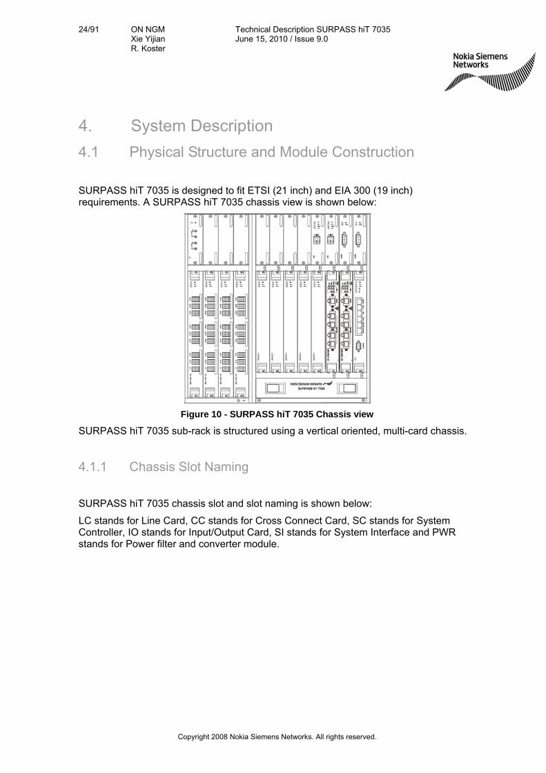
SURPASS hiT 7035 is designed to fit ETSI (21 inch) and EIA 300 (19 inch) requirements. A SURPASS hiT 7035 chassis view is shown below:
Figure 10 - SURPASS hiT 7035 Chassis view
SURPASS hiT 7035 sub-rack is structured using a vertical oriented, multi-card chassis.
4.1.1 Chassis Slot Naming
SURPASS hiT 7035 chassis slot and slot naming is shown below:
LC stands for Line Card, CC stands for Cross Connect Card, SC stands for System Controller, IO stands for Input/Output Card, SI stands for System Interface and PWR stands for Power filter and converter module.

25/91 ON NGM Xie Yijian R. Koster
Technical Description SURPASS hiT 7035 June 15, 2010 / Issue 9.0
Copyright 2008 Nokia Siemens Networks. All rights reserved.
Figure 11 - SURPASS hiT 7035 chassis slot naming
4.1.2 SURPASS hiT 7035 interface options
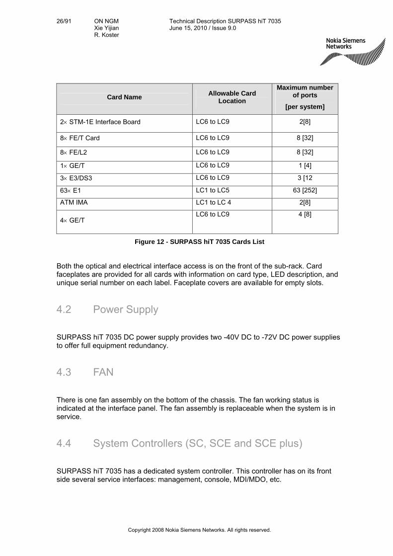
In the following table all interface options provided by SURPASS hiT 7035 are listed.
Card Name Allowable Card
Location
Maximum number of ports
[per system]
Cross Connect Card with 1xSTM-4/-1 CC1, CC2 1 [2]
Cross Connect Card with 1xSTM-16/-4 CC1, CC2 1 [2]
Cross Connect Card with 2xSTM-16 or 1*STM-16+4*STM-4/1
CC1, CC2 5 [10]
1 STM-4 Line Interface Board LC6 to LC9 1 [4]
2 STM-1 Line Interface Board LC6 to LC9 2 [8]
4 STM-1 Line Interface Board LC6 to LC9 4 [16]
LC2
LC4
LC3
CC w/ STM-16/4/1
CC w/ STM-16/4/1
LC5
F
A
IO 4 IO 1 IO 2 IO 3 SCE
SI IO5 IO7 LC8
LC7
LC10
LC9
IO6 LC11
LC1
LC6
PWR
PWR
26/91 ON NGM Xie Yijian R. Koster
Technical Description SURPASS hiT 7035 June 15, 2010 / Issue 9.0
Copyright 2008 Nokia Siemens Networks. All rights reserved.
Card Name Allowable Card
Location
Maximum number of ports
[per system]
2 STM-1E Interface Board LC6 to LC9 2[8]
8 FE/T Card LC6 to LC9 8 [32]
8 FE/L2 LC6 to LC9 8 [32]
1 GE/T LC6 to LC9 1 [4]
3 E3/DS3 LC6 to LC9 3 [12
63 E1 LC1 to LC5 63 [252]
ATM IMA LC1 to LC 4 2[8]
4 GE/T LC6 to LC9 4 [8]
Figure 12 - SURPASS hiT 7035 Cards List
Both the optical and electrical interface access is on the front of the sub-rack. Card faceplates are provided for all cards with information on card type, LED description, and unique serial number on each label. Faceplate covers are available for empty slots.
4.2 Power Supply
SURPASS hiT 7035 DC power supply provides two -40V DC to -72V DC power supplies to offer full equipment redundancy.
4.3 FAN
There is one fan assembly on the bottom of the chassis. The fan working status is indicated at the interface panel. The fan assembly is replaceable when the system is in service.
4.4 System Controllers (SC, SCE and SCE plus)
SURPASS hiT 7035 has a dedicated system controller. This controller has on its front side several service interfaces: management, console, MDI/MDO, etc.

27/91 ON NGM Xie Yijian R. Koster
Technical Description SURPASS hiT 7035 June 15, 2010 / Issue 9.0
Copyright 2008 Nokia Siemens Networks. All rights reserved.
4.5 System Interface Panel (SI)
The system interface panel provides the synchronization interfaces (T3 and T4).
4.6 Cross-Connect Switching (CC)
The CC card provides a cross connect function. To fit the customers’ different application economically, the SURPASS hiT 7035 provide three types of CC cards: one with 15.2G/5G with 1 STM-16/-4, one with 7.2G/2.5G with 1 STM-4/-1 and one with 32.8G/10G and 2*STM-16 or 1*STM-16 + 4*STM-4/1.
4.7 SDH Interfaces
SURPASS hiT 7035 provides following SDH interfaces:
1 STM-4 Interface Board
2 STM-1 Interface Board
4 STM-1 Interface Board
2 STM-1E interface Card
4.7.1 1x STM-4 Interface Board
This board provides 1 optical interface with a signal rate of 622 Mbits/s. The STM-4 interface is fully compliant with ITU-T G.707 and G.957 standards. This module supports hot swappable SFP optical module. The STM-4 optical interface on this board can be paired with any STM-4 interface on another board for 2-fiber STM-4 ring closure. The STM-4 ring supports MS-SPRING, MSP, and SNCP protection function.

28/91 ON NGM Xie Yijian R. Koster
Technical Description SURPASS hiT 7035 June 15, 2010 / Issue 9.0
Copyright 2008 Nokia Siemens Networks. All rights reserved.
4.7.2 2 STM-1 Interface Board
This board provides 2 optical interfaces with a signal rate of 155 Mbits/s. The STM-1 interfaces are fully compliant with ITU-T G.707 and G.957 standards. This module supports two hot swappable SFP optical modules. On STM-1 level MSP and SNCP protection is supported.
4.7.3 4 STM-1 Interface Board
This board provides 4 optical interfaces with a signal rate of 155 Mbits/s. The STM-1 interfaces are fully compliant with ITU-T G.707 and G.957 standards. This board supports four hot swappable SFP optical modules or SFP electrical modules. On STM-1 level MSP and SNCP protection is supported.
4.7.4 2 STM-1E (W/P) Interface
This card offers 2 STM-1E electrical interface, and supports redundant (1+1) 2 STM-1E card protection.
Using the redundancy option implement the following devices two 2 STM-1E functional cards and one 2 STM-1E I/O board.
The 2 STM-1E functional card performs 2 STM-1E signal mapping and framing function.
The 2 STM-1E EC board provide 2 STM-1E interfaces. This board is connected to both 2 STM-1E (working) and 2 STM-1E (protection) card simultaneously.
Under normal condition, the STM-1E client interface is connected to the 2 STM-1E (working) card. If the 2 STM-1E (working) card fails, the 2 STM-1E EC board will switch to the 2 STM-1E (protection) card.
Figure 13 depicts the functional block diagram of 2 STM-1E (W/P) card protection.

29/91 ON NGM Xie Yijian R. Koster
Technical Description SURPASS hiT 7035 June 15, 2010 / Issue 9.0
Copyright 2008 Nokia Siemens Networks. All rights reserved.
2x STM-1E transceiver & Framing function2 STM-1E EC
2 STM-1E (W)
2x STM-1E transceiver & Framing function
SC
SelectorRelay
To CC boardvia Backplane
2 STM-1E (P) To client equipment
Figure 13 - Functional block diagram of 2 STM-1E (W/P) card protection
4.8 PDH and Data Service Interfaces
SURPASS hiT 7035 supports the following service cards:
Data cards:
8 FE/L2 Service Interface Card
8 FE/T Service Interface Card
1x GE/T Service Interface Board
4x GE/T Service Interface Board
PDH cards:
3 E3/DS3 (W/P) Interface Card
63 E1 (W/P) Interface Card
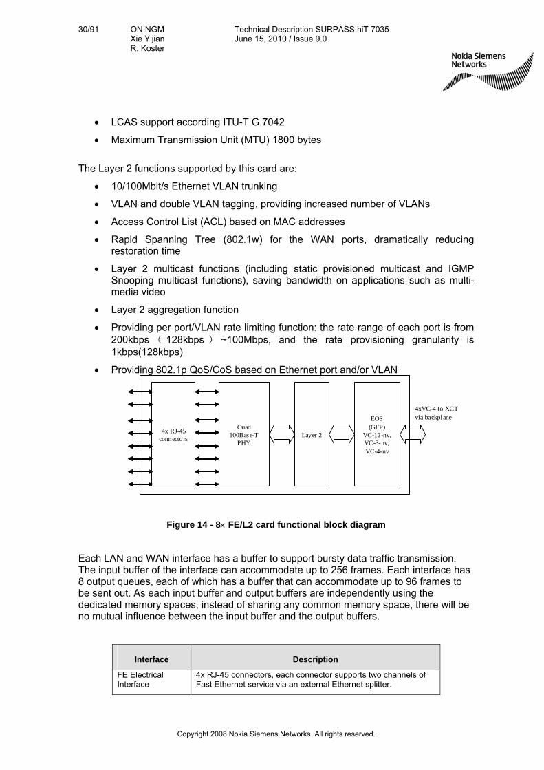
4.8.1 8x FE/L2 Service Interface Card
This card provides 410/100M Base-T interfaces (RJ-45), One RJ45 can be used for two LAN ports, There are eight WAN ports on the network side. Up to 8x 10/100M traffic can be aggregated at WAN port side and forwarded to a SDH line interface for transmission with up to 4 VC-4 at the network / WAN side.
Ethernet over SDH functions by this card are:
Supports GFP encapsulation (ITU-T G.7041/Y.1303)
Scalable bandwidth through VC-12-nv (n=1,…,46) and VC-3-nv (n=1,2)
30/91 ON NGM Xie Yijian R. Koster
Technical Description SURPASS hiT 7035 June 15, 2010 / Issue 9.0
Copyright 2008 Nokia Siemens Networks. All rights reserved.
LCAS support according ITU-T G.7042
Maximum Transmission Unit (MTU) 1800 bytes
The Layer 2 functions supported by this card are:
10/100Mbit/s Ethernet VLAN trunking
VLAN and double VLAN tagging, providing increased number of VLANs
Access Control List (ACL) based on MAC addresses
Rapid Spanning Tree (802.1w) for the WAN ports, dramatically reducing restoration time
Layer 2 multicast functions (including static provisioned multicast and IGMP Snooping multicast functions), saving bandwidth on applications such as multi-media video
Layer 2 aggregation function
Providing per port/VLAN rate limiting function: the rate range of each port is from 200kbps ( 128kbps ) ~100Mbps, and the rate provisioning granularity is 1kbps(128kbps)
Providing 802.1p QoS/CoS based on Ethernet port and/or VLAN
Layer 2Ouad
100Base-T PHY
EOS(GFP)
VC-12-nv,VC-3-nv,VC-4-nv
4xVC-4 to XCT via backplane
4x RJ-45connectors
Figure 14 - 8 FE/L2 card functional block diagram
Each LAN and WAN interface has a buffer to support bursty data traffic transmission. The input buffer of the interface can accommodate up to 256 frames. Each interface has 8 output queues, each of which has a buffer that can accommodate up to 96 frames to be sent out. As each input buffer and output buffers are independently using the dedicated memory spaces, instead of sharing any common memory space, there will be no mutual influence between the input buffer and the output buffers.
Interface Description
FE Electrical Interface
4x RJ-45 connectors, each connector supports two channels of Fast Ethernet service via an external Ethernet splitter.

31/91 ON NGM Xie Yijian R. Koster
Technical Description SURPASS hiT 7035 June 15, 2010 / Issue 9.0
Copyright 2008 Nokia Siemens Networks. All rights reserved.
Interface Description
Standard compliance
10M BASE-T (IEEE 802.3)
100M BASE-T (IEEE 802.3u)
Data rate supported
10Mbit/s (half-duplex, full-duplex, flow control)
100Mbit/s (half-duplex, full-duplex, flow control)
Cables:
Use of 4 ports only:
10/100 BASE-T: 100 Ohms two pairs shielded twisted pair cable (STP) and two pairs of unshielded twisted pair cable (Category 5 UTP). The reaching distance is up to 100m
Use of 8 ports:
10/100 BASE-T: 100 Ohms four pairs shielded twisted pair cable (Category 5) in combination with 2-in-1 RJ45 splitter box.
Figure 15 - 8 FE/L2 interface card external interfaces
Name Color Status Functional Description
On The link is up.
A green LED per interface indicates the
link up and down OFF The link is down.
ON Transmitting or receiving data.
(FE port LED)
A yellow LED per interface indicates the
activity OFF No data.
Figure 16 - 8 FE/L2 card LEDs
4.8.2 8x FE/T Service Interface Card
This card has 8 10/100M Base-T IEEE 802.3 compatible Ethernet interface ports, and can provide transparent transmission for up to 8x 10/100M connections. The total available bandwidth on the network side is 4 VC-4 equivalent.
Supports GFP encapsulation (ITU-T G.7041/Y.1303)
Scalable bandwidth through VC-12-nv (n=1,…,46) and VC-3-nv (n=1..3)
LCAS support according ITU-T G.7042
Maximum Transmission Unit (MTU) 1800 bytes up to 9600 bytes (jumbo frame support)

32/91 ON NGM Xie Yijian R. Koster
Technical Description SURPASS hiT 7035 June 15, 2010 / Issue 9.0
Copyright 2008 Nokia Siemens Networks. All rights reserved.
Even with minimal equipment investment, this Ethernet card still provides very attractive services to the end customers, like:
Scalable bandwidth without having to change interfaces
A transparent LAN service that hides the complexity of the WAN for end users (a WAN that looks like a LAN)
High availability LAN service because of end-to-end SDH protection switching
Octal 100Base-T
PHY
EOS (GFP, LAPS, VC-
12-nv, VC-3)
Network side:Total 4xVC4 bandwidth(to the backplane)
8x RJ-45connectors
Client side:Up to 8 FE signals
Figure 17 - 8 FE/T card functional block diagram
Interface Description
4x RJ-45 connectors, each connector supports two channels of Fast Ethernet service via an external Ethernet splitter.
Standard compliance
10M BASE-T (IEEE 802.3)
100M BASE-T (IEEE 802.3u)
Data rate supported
10Mbit/s (half-duplex, full-duplex, flow control)
100Mbit/s (half-duplex, full-duplex, flow control) FE Electrical Interface
Cables:
Use of 4 ports only:
10/100 BASE-T: 100 Ohms two pairs shielded twisted pair cable (STP) and two pairs of unshielded twisted pair cable (Category 5 UTP). The reaching distance is up to 100m
Use of 8 ports:
10/100 BASE-T: 100 Ohms four pairs shielded twisted pair cable (Category 5) in combination with 2-in-1 RJ45 Splitterbox.
Figure 18 - 8 FE/T interface card external interfaces
Name Color Status Functional Description
33/91 ON NGM Xie Yijian R. Koster
Technical Description SURPASS hiT 7035 June 15, 2010 / Issue 9.0
Copyright 2008 Nokia Siemens Networks. All rights reserved.
Name Color Status Functional Description
On
The link is up. A green LED per interface indicates the link up and down
OFF The link is down.
ON Transmitting or receiving data.
(FE port LED)
A yellow LED per interface indicates the activity OFF No data.
Figure 19 - 8 FE/T card LEDs
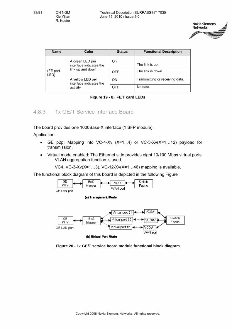
4.8.3 1x GE/T Service Interface Board
The board provides one 1000Base-X interface (1 SFP module).
Application:
GE p2p; Mapping into VC-4-Xv (X=1...4) or VC-3-Xv(X=1…12) payload for transmission.
Virtual mode enabled: The Ethernet side provides eight 10/100 Mbps virtual ports VLAN aggregation function is used.
VC4, VC-3-Xv(X=1…3), VC-12-Xv(X=1…46) mapping is available.
The functional block diagram of this board is depicted in the following Figure
Figure 20 - 1 GE/T service board module functional block diagram
34/91 ON NGM Xie Yijian R. Koster
Technical Description SURPASS hiT 7035 June 15, 2010 / Issue 9.0
Copyright 2008 Nokia Siemens Networks. All rights reserved.
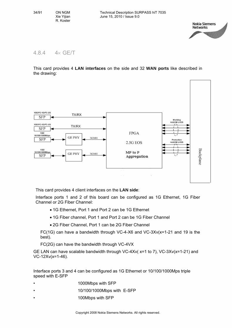
4.8.4 4 GE/T
This card provides 4 LAN interfaces on the side and 32 WAN ports like described in the drawing:
This card provides 4 client interfaces on the LAN side:
Interface ports 1 and 2 of this board can be configured as 1G Ethernet, 1G Fiber Channel or 2G Fiber Channel:
1G Ethernet, Port 1 and Port 2 can be 1G Ethernet
1G Fiber channel, Port 1 and Port 2 can be 1G Fiber Channel
2G Fiber Channel, Port 1 can be 2G Fiber Channel
FC(1G) can have a bandwidth through VC-4-X6 and VC-3Xv(x=1-21 and 19 is the best).
FC(2G) can have the bandwidth through VC-4VX
GE LAN can have scalable bandwidth through VC-4Xv( x=1 to 7), VC-3Xv(x=1-21) and VC-12Xv(x=1-46).
Interface ports 3 and 4 can be configured as 1G Ethernet or 10/100/1000Mps triple speed with E-SFP
• 1000Mbps with SFP
• 10/100/1000Mbps with E-SFP
• 100Mbps with SFP

35/91 ON NGM Xie Yijian R. Koster
Technical Description SURPASS hiT 7035 June 15, 2010 / Issue 9.0
Copyright 2008 Nokia Siemens Networks. All rights reserved.
GE LAN can have scalable bandwidth through VC-4Xv( x=1 to 7), VC-3Xv(x=1-21) and VC-12Xv(x=1-46).
10/100/1000 Base LAN can have scalable bandwidth through VC-4Xv( x=1 to 7), VC-3Xv(x=1-21) and VC-12Xv(x=1-46).
100-Base FX can have scalable bandwidth through VC-4Xv( x=1), VC-3Xv(x=1-3) and VC-12Xv(x=1-46).
On the WAN side this card provides 32 WAN (VCG) ports to share 16xVC-4 bandwidth on the backplane and each VC4 can be mapped into VC3 or VC12. The first WAN can have bandwidth till 14Xvc-4 so that it can used to aggregate more than two GE traffic
This card support two Modes
1. Port cross connection Port cross connection function can transport the Ethernet traffic through the SDH network using GFP-F, and transport the fiber channel packet using GFP-T
At the same time, it can support VLAN operate on the input packets includes:
1) Just forward without any VLAN operation.
2) Add a PVID based on Port
3) Stack a VLAN Tag
4) Strip VLAN tag at the egress
2. Port+VLAN cross connection (VLAN aggregation) At the same time, it can support VLAN operate on the input packets includes:
1) Forwarding the packet without any VLAN manipulation
2) Stacking a VLAN tag (double tag tunneling)
3) Ttranslating a VLAN ID (VLAN id replace)
4) Stripping the VLAN tag at the egress (new request)
For more information about Port Cross Connection and Port+VLAN Cross Connection feature, please refer to Appendix 9.3: Port Cross Connection and Port+VLAN Cross Connection
For hiT7035, 4xGE/T can be inserted on SLOT 8/9 when 33G/10G CC is configured.
Traffic manager include Policing (CIR/PIR), QOS (VLAN priority) and Schedule (WRED/SP/WRR) is supported in this 4*GE/T card.

36/91 ON NGM Xie Yijian R. Koster
Technical Description SURPASS hiT 7035 June 15, 2010 / Issue 9.0
Copyright 2008 Nokia Siemens Networks. All rights reserved.
4.8.5 3 E3/DS3 (W/P) Interface Card
This card has 3 E3/DS3 software configurable interfaces; each E3/DS3 signal is mapped into a Lower Order VC-3 and forwarded to line interface for transmission. The E3/DS3 interface uses CC4 connector.
Figure 21 depicts the functional block diagram of 3 E3/DS3 (W/P) card protection.
Mapping each E3/DS3 To VC-3 3 E3/DS3 EC
3 E3/DS3 (W)
Mapping each E3/DS3 To VC-3
SC
SelectorRelay
To CC boardvia Backplane
3 E3/DS3 (P)
Figure 21 - Functional block diagram of 3 E3/DS3 (W/P) card protection
The SURPASS hiT 7035 chassis supports 1:3 protection for the E3/DS3 card.
4.8.6 63 E1 (W/P) Interface Card
The 63 E1 interface card contains the following two types of long cards:
(1) 63 E1 Function Card
(2) 63 E1 EC (Electrical Connectors) Card with 75Ohm/120Ohm version connector.
In the retiming mode, the transmitter eliminates wander and jitter in the incoming clock.
While the rate of the outgoing 2 Mbit/s or 2MHz signal is normally equal to the rate of the 2 Mbit/s or 2MHz signal going into the SDH network, occasionally this relationship disappears. A retiming function is necessary for suppression of jitter and wander that the 2Mbit/s signal suffers during transmission in SDH and which makes the signal useless for carrying the synchronous frequency to the PDH domain.

37/91 ON NGM Xie Yijian R. Koster
Technical Description SURPASS hiT 7035 June 15, 2010 / Issue 9.0
Copyright 2008 Nokia Siemens Networks. All rights reserved.
To retime an outgoing 2 Mbit/s or 2MHz signal, means simply to retime this signal with the internal clock of the multiplexer equipment in which the desynchronization takes place. This can be done by reading the recovered 2Mbit/s or 2MHz signal into an elastic store and timing the output of the elastic store with the system clock.
When the device is set in the retiming mode all jitter and wander due to the multiplexing or demultiplexing process in the transmission is eliminated.
4.9 IMA Interfaces
4.9.1 IMA 126 E1 (W/P) Interface Card
The IMA 126 E1 interface card contains the following two types of long cards:
(1) IMA 126 E1 Function Card
(2) 2x STM-1 IMA IO Card
2x STM-1 ATM IO
2xSTM-1 ATM
126xE1 IMA (P)
126xE1 IMA (W)
To CC board via Backplane
Figure 22 –Functional block diagram of IMA (W/P) card protection
4.10 Optical Amplifier
This OA (Optical Amplifier) module provides uni-directional single optical amplifier function with optical performance monitoring capabilities.
Optical Amplifiers are available with 13, 15 or 18 dBm output power.
Additionally there is also a Pre-amplifier module available (20 dB).
These modules are designed to compensate losses in the entire C band and increasing therefore the span performance of the system without need for intermediated regenerators. The module functional building block diagram is shown below.

38/91 ON NGM Xie Yijian R. Koster
Technical Description SURPASS hiT 7035 June 15, 2010 / Issue 9.0
Copyright 2008 Nokia Siemens Networks. All rights reserved.
EDFA Module
Embedded CPU
RS-232
FPGA
OA Card
Optical Signal IN
Optical Signal OUT
To SC (System Controller)
Figure 23 – OA module functional building block diagram
The EDFA (Erbium Doped Fiber Amplifier) sub-module is the core building block for this card. It provides optical signal amplification function. With integrated fast digital circuit and advanced software, the EDFA can be configured to operate at APC, ACC or AGC mode.
APC (automatic power control) mode: In this mode, the optical output power is
maintained constant by adjusting the laser pump current to compensate minor
changes in OA input power, component aging, and temperature variation. This
mode is mainly used in post-amplifier application.
AGC (automatic gain control) mode: In this mode, the OA provides constant gain
power by adjusting the pump laser current to compensate minor changes in
component aging and temperature. This mode is mainly used in pre-amplifier
application.
ACC (automatic current control) mode: In this mode, the pump laser current is
maintained constant.
These modes can be set through software according to customer’s requirements. In addition, other significant parameters that need to be pre-set are:
Input optical power low threshold
Output optical power low threshold

39/91 ON NGM Xie Yijian R. Koster
Technical Description SURPASS hiT 7035 June 15, 2010 / Issue 9.0
Copyright 2008 Nokia Siemens Networks. All rights reserved.
Low and high temperature threshold for output power shutdown
This OA provides the following performances monitoring parameters:
OA Input Power (dBm), precision to 0.01dBm
OA Output Power (dBm), precision to 0.01dBm
OA Module Gain (dB), precision to 0.01dB
OA Pump Power (mW), precision to 0.01mW
OA module internal temperature, precision to 0.1 C degree
OA module pump drive current, precision to 0.1 A
OA power module power supply voltage, precision to 0.01V
This OA module board can be configured to use one of the following 4 EDFA sub-modules:
Booster 13dBm
Booster 15dBm
Booster 18dBm
Pre-amp 20dB
All EDFA sub-modules above use single-stage or dual-stage un-cooled 980nm pump lasers.
OA Safety Procedures
The OA module safety procedures supported are described in the table below.
Feature Description
ALS After 500ms or more of continuous presence of the LOS defect, the laser will automatically shutdown; the reduction of the optical output power at OA input port occurs within 800ms from the moment loss of optical signal occurs at OA output port.
Whenever the OA’s input signal vanishes, the OA’s optical output signal will be shut down. When the input signal returns, the output power will be restored.
Automatic Link restore
- The minimum optical signal restore delay is 100s. - The activation for Transmitter /Receiver is less than 0.85s. - The maximum deactivation time of booster and preamplifiers is 100 ms. - The maximum activation time of an booster is 100 ms. - The maximum activation time of preamplifier is 300ms.

40/91 ON NGM Xie Yijian R. Koster
Technical Description SURPASS hiT 7035 June 15, 2010 / Issue 9.0
Copyright 2008 Nokia Siemens Networks. All rights reserved.
Feature Description
Manual Restore
"Manual restart" or "Manual restart for test" can only be activated when the laser is shut down.
Figure 24 – OA module safty procedure
Interface Description
Connector Type LC connector
Pre-amp -35 to -10 dBm Optical Interface Input power range Booster
amp. -6 to +3 dBm
Figure 25 – OA card external interfaces
Name Color Status Functional Description
ON There are fault conditions presented in this card. Fault Red
OFF This card is in normal condition.
ON The OA optical link is normal. Link 1 Green
OFF The optical link is down.
Figure 26 – OA card LEDs
4.11 User Channel (F1)
Two 64kbps G.703 interfaces are provided and the following SDH Overhead bytes can be allocated: E1, E2 and/or F1.
4.12 Engineering Order Wire (EOW)
The hiT 7035 uses VoIP (H.323) technology to provide the EOW function on a DCC channel or uses an external data network.
The hiT 7035 VoIP based EOW provides unicast and multicast calling, and broadcast communications.
Traditional XOW over E1/E2/F1 will be implemented via an external XOW box.
For hiT 7035:
There are one RJ45s on the SC card. Users may totally select all the channels of E1/E2 from the system. And will be terminated by the system. There is no limitation on the card
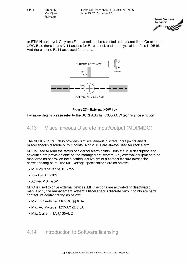
41/91 ON NGM Xie Yijian R. Koster
Technical Description SURPASS hiT 7035 June 15, 2010 / Issue 9.0
Copyright 2008 Nokia Siemens Networks. All rights reserved.
or STM-N port level. Only one F1 channel can be selected at the same time. On external XOW Box, there is one V.11 access for F1 channel, and the physical interface is DB15. And there is one RJ11 accessed for phone.
SURPASS hiT 7025 / 7035
SURPASS hiT 70 XOW
RJ 45 Cable
EOWC
Phone Set
Figure 27 – External XOW box
For more details please refer to the SURPASS hiT 7035 XOW technical description
4.13 Miscellaneous Discrete Input/Output (MDI/MDO)
The SURPASS hiT 7035 provides 8 miscellaneous discrete input points and 8 miscellaneous discrete output points (4 of MDOs are always used for rack alarm).
MDI is used to read the status of external alarm points. Both the MDI description and severities are provision able on the management system. Any external equipment to be monitored must provide the electrical equivalent of a contact closure across the corresponding pairs. The MDI voltage specifications are as below:
MDI Voltage range: 0~ -75V
Inactive: 0~ -10V
Active: -18~ -75V
MDO is used to drive external devices. MDO actions are activated or deactivated manually by the management system. Miscellaneous discrete output points are hard contact, its contact rating as below:
Max DC Voltage: 110VDC @ 0.3A
Max AC Voltage: 125VAC @ 0.3A
Max Current: 1A @ 30VDC
4.14 Introduction to Software licensing

42/91 ON NGM Xie Yijian R. Koster
Technical Description SURPASS hiT 7035 June 15, 2010 / Issue 9.0
Copyright 2008 Nokia Siemens Networks. All rights reserved.
Mandatory SW items
Optional SW items
Upgrade SW items
SW Maintenance items
Up to now SW licenses for Next Generation Metro equipment were un-recognized add-on items and the sales of these products have been dominated by HW selling. The SW license structure guarantees an optimized Network performance with minimum TCO (Total Cost of Ownership) by customized feature set. Within the hiT 70xx portfolio there are several features are being introduced like capacity based licenses, support of Matrix protection, support of extension shelves and ASON/GMPLS.
This SW license structure allows following equipment configuration principles:
• Offer only what is actually required
• Exclude non-mandatory features explicitly
• Tailoring of SW bundles allows up-sell potential
• Protect the individual SW value drivers by selling them separately
• Do not automatically design & price all SW features for the whole network
4.14.1 General Structure of new SW items
The Software item structure implemented within the product line Next Generation Metro
are divided into 3 general categories: mandatory SW license items, optional application
feature SW license items and upgrade SW license items. These are further represented
in the following document by a colour code indicated in the drawing below.
Figure 28: Software license structure in Next Generation Metro
Mandatory SW items

43/91 ON NGM Xie Yijian R. Koster
Technical Description SURPASS hiT 7035 June 15, 2010 / Issue 9.0
Copyright 2008 Nokia Siemens Networks. All rights reserved.
The mandatory Software items represent the basic functionality of the system, and one
of these core licenses are mandatory to be equipped for each equipment core.
Optional SW items
The optional Software items are items that represent additional types of functionality.
These can be:
Additional optional feature packages
Additional functionality related with HW configuration
Additional capacity
Upgrade SW items
The upgrade Software items are available for each individual product to provide
release upgrades. Release upgrades are in general upgrades where the succeeding
release contains a higher feature set. This is in general represented by a number in the
release name of the product.
Core Upgrade SW item
The Core Upgrade Software item is required for each node that shall be extended from
a 15.2G to a 32.8G capacity.
SW Maintenance items
The Software Maintenance items are available for each individual product to provide
maintenance related services, namely to solve technical queries (to provide qualified
answers and assistance for any general technical/operational queries), for trouble
resolution (to handle customer reported suspected defects and o deliver workarounds
and/or final solutions) and to provide software updates (to ensure a regular, proactive,
delivery of software update packages with respective release documentation).
4.14.2 Software license structure of SURPASS hiT 7035

44/91 ON NGM Xie Yijian R. Koster
Technical Description SURPASS hiT 7035 June 15, 2010 / Issue 9.0
Copyright 2008 Nokia Siemens Networks. All rights reserved.
SURPASS hiT 7035 is a versatile network element having the equipping option as ADM for STM-1/-4 (equipped with a small switch matrix) or as ADM for STM-4/-16 (equipped with a large switch matrix).
Therefore there are three different mandatory core licenses, an ADM-1/4 core license, an ADM-4/16 license and an ADM-1/-4/-16 license.
The main optional feature that SURPASS hiT 7035 offer is equipment protection to significantly increase the reliability of the network elements. Increased reliability is significant value add, therefore by equipping a switch matrix protection, a matrix protection license is needed.
Upgrade SW items are available to a release upgrade (from a release x.y to a release x.(y+1) or increase of x).
Figure 29: Software license structure of SURPASS hiT 7035
A special case exists for the SURPASS hiT 7035 Release 4.0. This equipment release
only serves as E1 extension shelf for the systems SURPASS hiT 7060, hiT 7060HC,
hiT7065 and hiT 7080. For each extension shelf hiT 7035 Release 4.0 and 4.0.1 used
45/91 ON NGM Xie Yijian R. Koster
Technical Description SURPASS hiT 7035 June 15, 2010 / Issue 9.0
Copyright 2008 Nokia Siemens Networks. All rights reserved.
along with one of the above mentioned network elements, an E1 extension shelf license
is mandatorily required.
Figure 30: Software license structure of SURPASS hiT 7035 – E1 Extension shelf
5. Protection and Redundancy
5.1 Network Protection
SURPASS hiT 7035 supports multiple layer network protection functions and multiple layer protection escalation. The network protection functions supported are:
MS-SPRing, in compliance with ITU-T G.841
MSP 1+1 protection, revertive or non-revertive modes, in compliance with ITU-T G.841
SNCP at VC-12, VC-3, VC-4, VC-4-4c level in compliance with ITU-T G.841
Rapid Spanning Tree Protocol (RSTP) to provide Layer 2 Ethernet data protection by converging data to another path, in compliance with IEEE 802.1w protocol
5.1.1 MS-SPRing
SURPASS hiT 7035 supports 2 fibers MS-SPRing at STM-4/-16 levels. The protection (detection and switching) is guaranteed to be finished within 50ms. The wait-to-restore time is user configurable with a default value of 5 minutes. The system also supports force switching and manual switching.
For example, in an STM-4 ring with the MS-SPRing function enabled, a total of 4 AU4s are divided evenly into 2 groups, working AU4s (time slots 1 and 2) and protection AU4s (time slots 3 and 4).
The SURPASS hiT 7035 MS-Spring implementation supports also low priority traffic by supporting NUT feature (Non-preempt-able Unprotection Traffic).
5.1.2 MSP
1+1 MSP (G.841/Clause 7) protects an STM-N link between two adjacent SDH MS (multiplexing section) elements.

46/91 ON NGM Xie Yijian R. Koster
Technical Description SURPASS hiT 7035 June 15, 2010 / Issue 9.0
Copyright 2008 Nokia Siemens Networks. All rights reserved.
SURPASS hiT 7035 supports 1+1 multiplex section protection (MSP) on all STM-N optical ports. The MSP 1+1 can be either uni-direction or bi-direction. The protection time is less than 50ms.
SURPASS hiT 7035 also supports Manual Switch and Forced Switch of MSP, revertive and non-revertive MSP.
5.1.3 SNCP
SURPASS hiT 7035 supports Sub-Network Connection (SNC) protection (ITU-T G.841). It is available at VC-12, VC-3, VC-4 and VC-4-4c level. SURPASS hiT 7035 supports VC-4/-3/-12 SNC protection between any pair of VC-4/3/12s in any STM-N cards and also supports VC-4-4c SNC protection in STM-4 cards and STM-16 ports.
The protection switch time for SNC protection is less than 50 ms.
The SNC protection scheme supported in SURPASS hiT 7035 is an inherently monitored SNCP (SNCP/I) or non-intrusively monitored SNCP (SNCP/N). The SNCP protected VC-4s are protected against AIS or LOP at the AU-4 level (server layer defects) and against misconnections (trace identifier mismatch or VC-4 dTIM), disconnections (unequipped signal or VC-4 dUNEQ), or signal degradations (VC-4 dDEG) in the VC-4 itself. Likewise, SNCP protected VC-3s and VC-12s are protected against TU3/12-AIS, TU3/12-LOP (server layer defects), VC-3/12 dTIM, dUNEQ, and dDEG. Also SNCP protected VC-4-4cs are protected against AU-4-4c-LOP/AIS, MS-AIS, LOF, LOS, VC-4-4c- dTIM, dUNEQ and dDEG.
The SURPASS hiT 7035 SNCP implementation supports also non-revertive, single-ended and drop & continues features.
An advantage of SNCP is the flexibility to select any segment of the path for protection. The SNC protection can be applied to an end-to-end (from source to sink termination point) VC-n path, or to one or multiple links within the end-to-end path. It is also simple and easy to implement, as there is no signaling required between the source and destination nodes.
5.1.4 DNI
SURPASS hiT7035 supports Dual Node Inter-working (DNI) protection (ITU-T G.841). It is a protection mechanism between two rings with dual node connections. Each ring may be configured for MS-shared protection or SNCP protection.
The ring interconnection can work at STM-1 electrical or STM-N optical rate level.
The DNI architecture has the capacity of protecting against the failure of one interconnecting node, two interconnecting nodes, or the connection between the two interconnecting nodes. It depends on detecting path defects. To avoid propagation of failures when possible, a hold-off time is allowed.
The service interrupt time by external command and node failure, signal failure, card failure, SFP failure for DNI/DRI protection is less than hold-off time plus 50ms.

47/91 ON NGM Xie Yijian R. Koster
Technical Description SURPASS hiT 7035 June 15, 2010 / Issue 9.0
Copyright 2008 Nokia Siemens Networks. All rights reserved.
5.1.5 LCAS
SURPASS hiT 7035 supports the combination of VCAT and LCAS to provide VC-4, VC-3 or VC-12 level protection. LCAS allows hitless adjustment of the size of a virtually concatenated group of channels.
For example, whenVC-4-nv bandwidth is used to transmit data traffic through the network. In the case that certain VC-4s in the same VC-4-nv group fail, SURPASS hiT 7035 will use LCAS to delete the failed VCs from the group, and the traffic is dynamically, or on the fly adapted to the rest VC-4s bandwidth for transmission. Without LCAS, partial bandwidth failure will result in the failure of the end-to-end traffic transmission.
When the failure is repaired, the LCAS will automatically add (recover) the deleted VC-4s to the VC group.
5.1.6 Ethernet Shared Protection Ring
SURPASS hiT 7035 supports L2 switching and RSTP (IEEE 802.1w compliant) based L2 protection in ESR. The convergence time can reach less than two seconds. RSTP based protection is different from SDH layer protection. SDH protection is considered a physical layer protection, while RSTP is a Layer 2 protection. When layer 2 Ethernet data fault is detected, even though the physical connectivity is good, RSTP will make the convergence of the data to another physical path.
5.1.7 Multiple Layers Protection
SURPASS hiT 7035 supports network protection functions in multiple layers. These layers are SDH and Ethernet data. In order to coordinate the protection activities between layers, SURPASS hiT 7035 provides a protection escalation mechanism. This uses different hold off times at different layers to make sure that lower layer protection occurs first. For example, in a fiber failure condition, SDH protection will be performed first. If SDH layer protection is successful, no Ethernet layer protection occurs (because it is not needed). However, if the SDH protection fails after a certain period of time (the hold off time for Ethernet layer protection), Ethernet layer protection will occur. That is, the higher the layer, the longer the hold off time will be. In this way, the system can fully take the advantage of the fast SDH protection (<50ms), and have multi-layer protections for higher system reliability.
For Ethernet services, if the layer protection fails (the failure is declared after a pre-defined hold off time; for example 100ms), the RSTP in the Ethernet layer will react to the failure and provide the protection by converging the data to an alternative path. In the ESR, the alternative path is the path on the other side of the ring. The hold off time in the Ethernet layer is user provision able.

48/91 ON NGM Xie Yijian R. Koster
Technical Description SURPASS hiT 7035 June 15, 2010 / Issue 9.0
Copyright 2008 Nokia Siemens Networks. All rights reserved.
5.2 Equipment Redundancy and Protection
5.2.1 Redundant Power Supply
SURPASS hiT 7035 provides optional 1+1 DC power supply protection. The DC power voltage is -40 to -72 V. Both power modules are active and coupled via an “OR” function to share the load current.
SURPASS hiT 7035 permits convenient field replacement of either power module without affecting traffic.
5.2.2 Redundant Cross-Connect
SURPASS hiT 7035 provides optional redundant cross-connect and timing card.
5.2.3 Electrical Interface Module Protection
SURPASS hiT 7035 provides the following electrical interface card protection:
(1) 1:4 63 E1 card protection (revertive)
(2) 1:3 3 E3/DS3 (W/P) card protection (non-revertive)
(3) 1+1 2 STM-1E (W/P) card protection (non-revertive)
5.2.4 Protection under Abnormal Condition
Software download protection: when power fails during software download, SURPASS hiT 7035 BIOS will be written protected. The BIOS is guaranteed not to start the uncompleted software program or data file. After the power recovery, SURPASS hiT 7035 supports continued software downloading. All application software and data files can be downloaded to the NE while the NE is still in-service. The software download verification process prevents data errors from transmission.
Software upgrade protection: SURPASS hiT 7035 controller contains two copies of the system software. During the software upgrade, one copy will be replaced by the new version of the software. After the new version is confirmed, the switch over to the new version does not affect the service traffic, and the existing system setting and configuration are maintained. If the system upgrade fails, the system can be switched back to the old version. Only when the new software version is confirmed working properly, can the old version be erased.

49/91 ON NGM Xie Yijian R. Koster
Technical Description SURPASS hiT 7035 June 15, 2010 / Issue 9.0
Copyright 2008 Nokia Siemens Networks. All rights reserved.
5.2.5 Software Fault Tolerance
The software design of SURPASS hiT 7035 NE adopts the principle of software engineering, involving a top-down and object-oriented software design methods. Advanced software developing management and designing technology assure the high quality and reliability of NE software.
SURPASS hiT 7035 provides multiple protections for software programs and data with self-checking and self-recovering functions.
Data transmission checking and re-transmitting mechanism are implemented in all control signal transmission channels between modules to minimize the transmitting errors.
Adopted internal watchdog-circuit in CPU to avoid the impact of software deadlock or shut down. No service is affected when the software performs warm reset.
Adopted common software platform approach: SURPASS hiT 7035 supports code-sharing and re-using as many as field proven codes to provide higher software reliability.
5.2.6 Data Security
SURPASS hiT 7035 adopts database module technology and manages data uniformly, which enhances the data security:
Database and database files each have a data checking function.
Database files are protected according to importance level of data. Errors of lower level database files will not affect higher level database files
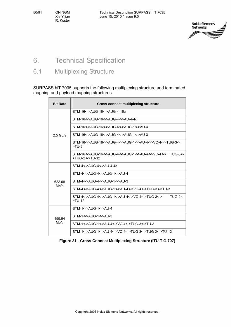
50/91 ON NGM Xie Yijian R. Koster
Technical Description SURPASS hiT 7035 June 15, 2010 / Issue 9.0
Copyright 2008 Nokia Siemens Networks. All rights reserved.
6. Technical Specification
6.1 Multiplexing Structure
SURPASS hiT 7035 supports the following multiplexing structure and terminated mapping and payload mapping structures.
Bit Rate Cross-connect multiplexing structure
STM-16<->AUG-16<->AUG-4-16c
STM-16<->AUG-16<->AUG-4<->AU-4-4c
STM-16<->AUG-16<->AUG-4<->AUG-1<->AU-4
STM-16<->AUG-16<->AUG-4<->AUG-1<->AU-3
STM-16<->AUG-16<->AUG-4<->AUG-1<->AU-4<->VC-4<->TUG-3<->TU-3
2.5 Gb/s
STM-16<->AUG-16<->AUG-4<->AUG-1<->AU-4<->VC-4<-> TUG-3<->TUG-2<->TU-12
STM-4<->AUG-4<->AU-4-4c
STM-4<->AUG-4<->AUG-1<->AU-4
STM-4<->AUG-4<->AUG-1<->AU-3
STM-4<->AUG-4<->AUG-1<->AU-4<->VC-4<->TUG-3<->TU-3
622.08 Mb/s
STM-4<->AUG-4<->AUG-1<->AU-4<->VC-4<->TUG-3<-> TUG-2<->TU-12
STM-1<->AUG-1<->AU-4
STM-1<->AUG-1<->AU-3
STM-1<->AUG-1<->AU-4<->VC-4<->TUG-3<->TU-3
155.54 Mb/s
STM-1<->AUG-1<->AU-4<->VC-4<->TUG-3<->TUG-2<->TU-12
Figure 31 - Cross-Connect Multiplexing Structure (ITU-T G.707)

51/91 ON NGM Xie Yijian R. Koster
Technical Description SURPASS hiT 7035 June 15, 2010 / Issue 9.0
Copyright 2008 Nokia Siemens Networks. All rights reserved.
Bit Rate Terminated Mapping Structure Container
2.5 Gb/s STM-16<->AUG-16<->AUG-4<->AUG-1<->AU-4<->VC-4
C-4
622.08 Mb/s STM-4<->AUG-4<->AUG-1<->AU-4<->VC-4 C-4
155.54 Mb/s STM-1<->AUG-1<->AU-4<->VC-4 C-4
E3 (34Mbit/s, E31) E31 <-> C-3 <-> VC-3 C-3
DS3 (45Mbit/s, E32) E32 <-> C-3 <-> VC-3 C-3
E1 (2.048Mbit/s) E1 <-> C-12 <-> VC-12<-> TU-12<-> TUG-2 ……
C-12
10/100Mbit/s (FE) <-> GFP <-> C-12-Xv <-> VC-12- Xv (X=1..46)
C-12
10/100 Mb/s (FE) 10/100Mbit/s (FE) <-> GFP <-> C-3-Xv <-> VC-3-Xv (X=1..3)
C-3
1000Mbit/s (WAN port GE) <-> GFP <-> C-4-Xv <-> VC-4-Xv (X=1..4)
C-4
1000Mbit/s (WAN port GE) <-> GFP <-> C-3-Xv <-> VC-3-Xv (X=1..3)
C-3
1000 Mb/s (GE)
1000Mbit/s (WAN port GE) <-> GFP <-> C-12-Xv <-> VC-12-Xv (X=1..46)
C-12
FC(2G) FC(2G) <-> GFP <-> C-4-X12 <-> VC-4- X12 C-4
FC(1G) <-> GFP <-> C-4-X6 <-> VC-4- X6 C-4
FC(1G) FC(1G) <-> GFP <-> C-3-Xv <-> VC-3- Xv (X=19...21, 19 is the best fit)
C-3
10/100/1000Mbit/s LAN <-> WAN <-> GFP <-> C-4-Xv <-> VC-4- Xv (X=1...7)
C-4
10/100/1000Mbit/s LAN <-> WAN <-> GFP <-> C-3-Xv <-> VC-3- Xv (X=1...21)
C-3 10/100/1000M
10/100/1000Mbit/s LAN <-> WAN <-> GFP <-> C-12-Xv <-> VC-12- Xv (X=1...46)
C-12
Figure 32 - Terminated Mapping Structure
Virtual Container
Container Container Bit Rate Terminating Signal at Bit Rate
VC-4 C-4 149.76Mb/s STM-1, or VC-4-nv
Figure 33 - Payload Mapping
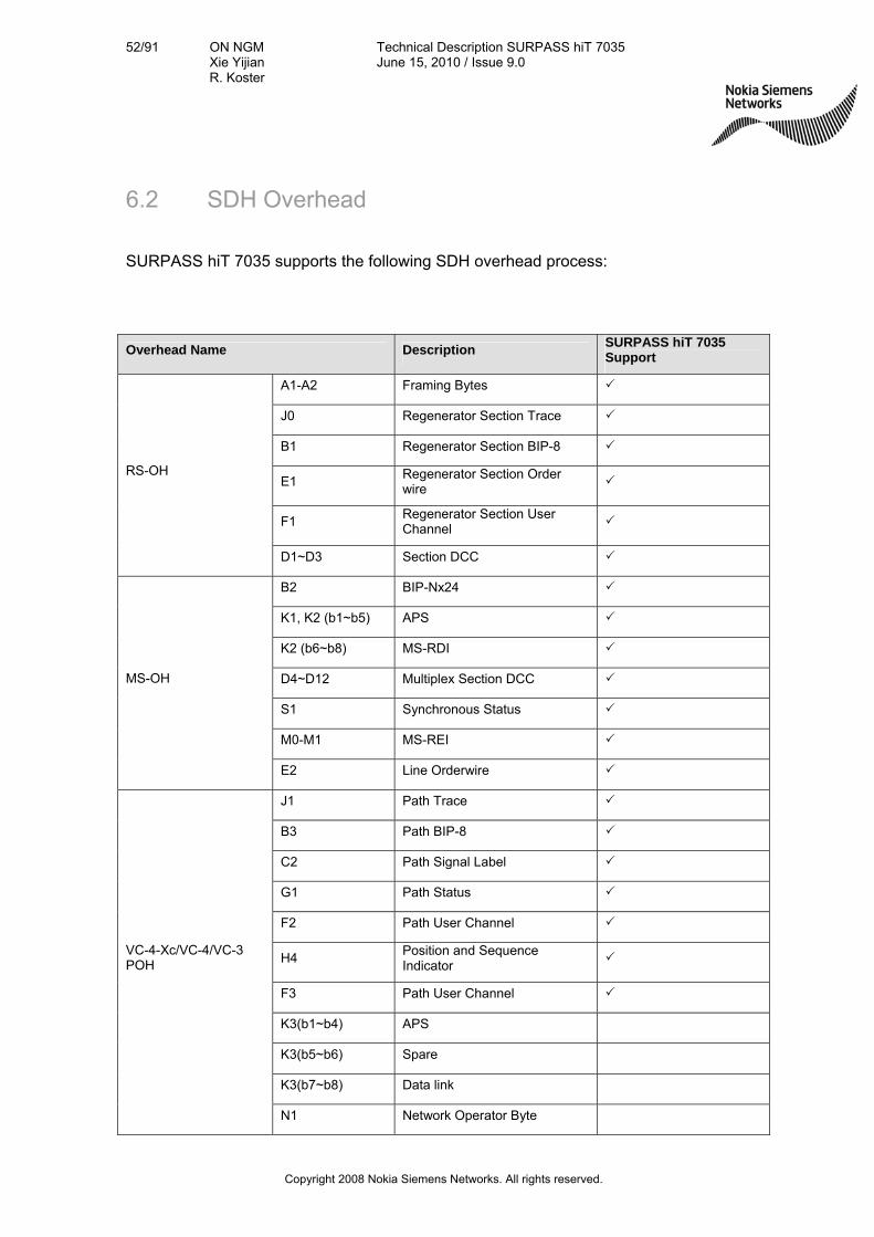
52/91 ON NGM Xie Yijian R. Koster
Technical Description SURPASS hiT 7035 June 15, 2010 / Issue 9.0
Copyright 2008 Nokia Siemens Networks. All rights reserved.
6.2 SDH Overhead
SURPASS hiT 7035 supports the following SDH overhead process:
Overhead Name Description SURPASS hiT 7035 Support
A1-A2 Framing Bytes
J0 Regenerator Section Trace
B1 Regenerator Section BIP-8
E1 Regenerator Section Order wire
F1 Regenerator Section User Channel
RS-OH
D1~D3 Section DCC
B2 BIP-Nx24
K1, K2 (b1~b5) APS
K2 (b6~b8) MS-RDI
D4~D12 Multiplex Section DCC
S1 Synchronous Status
M0-M1 MS-REI
MS-OH
E2 Line Orderwire
J1 Path Trace
B3 Path BIP-8
C2 Path Signal Label
G1 Path Status
F2 Path User Channel
H4 Position and Sequence Indicator
F3 Path User Channel
K3(b1~b4) APS
K3(b5~b6) Spare
K3(b7~b8) Data link
VC-4-Xc/VC-4/VC-3 POH
N1 Network Operator Byte

53/91 ON NGM Xie Yijian R. Koster
Technical Description SURPASS hiT 7035 June 15, 2010 / Issue 9.0
Copyright 2008 Nokia Siemens Networks. All rights reserved.
Overhead Name Description SURPASS hiT 7035 Support
V5(b1~b2) BIP-2
V5(b3) LP-REI
V5(b4) LP-RFI
V5(b5~b7) Signal Label
V5(b8) LP-RDI
J2 Path Trace
N2 Network Operator Byte
K4(b1~b4) APS
K4(b5~b7) Reserved
VC-2/VC-1
POH
K4(b8) Data Link
Figure 34 – SURPASS hiT 7035 supported SDH overhead process
6.3 Interface Types SURPASS hiT 7035 supports the following interfaces listed in Table below:
Interface Types Interface Name and Rates
Electrical Interface
10/100M Base-T
10/100/1000 Base-T
E1 (2048kbit/s)
E3/DS3
STM-1 el. (155.520Mbit/s)
Optical Interface
STM-1 (155.520Mbit/s)
STM-4 (622.080Mbit/s)
STM-16 (2.5 Gbit/s)
GE
FC
100M FX
Timing Interface 2048kbit/s
2048kHz
Auxiliary Management and Maintenance Interface) RS-232, RJ-45 (802.3 LAN)
TIF (MDO or MDI) RJ-45
Data Channels 64Kbps/s, G703, RJ45
Figure 35 – SURPASS hiT 7035 Interface Types
54/91 ON NGM Xie Yijian R. Koster
Technical Description SURPASS hiT 7035 June 15, 2010 / Issue 9.0
Copyright 2008 Nokia Siemens Networks. All rights reserved.
6.3.1 Electrical Interfaces
SURPASS hiT 7035 Ethernet 10/100M Base-T rate-adaptive electrical interface complies with IEEE Standard 802.3. The transmission media is 100 Ohms–two pairs shielded twisted pair cable (STP) and two pairs of unshielded twisted pair cable (Category 5 UTP); the interface connector is using standard RJ-45 (1000ohm) connector.
SURPASS hiT 7035 STM-1E interface complies with ITU-T G.703 Recommendation and uses CC4 connector (75 ohm) unbalanced.
SURPASS hiT 7035 E3/DS3 interface complies with ITU-T G.703 Recommendation and uses CC4 connector (75ohm) unbalanced.
SURPASS hiT 7035 E1 interface complies with ITU-T G.703 Recommendation, and uses 2mm High Density (75ohm or 120ohm) connector.
6.3.2 Optical Interfaces
SURPASS hiT 7035 optical interfaces comply with ITU-T Recommendations G.957 and G.691. The SFP optical modules are field replaceable.
Optical Interfaces:
STM-16 SFP interfaces S-16.1, L16.1 and L-16.2, V-16.2, U-16.2 also FC 2G.
STM-4 SFP interfaces S-4.1, L4.1, L-4.2 and V-4.2
STM-1 SFP interfaces I-1 S-1.1, L1.1, L1.2 and V-1.2 also 100M FX
GE SFP interfaces SX, LX, LH, ZX also FC(1G)
STM-1 electrical SFP interfaces
Multi-rate CWDM SFP interfaces G. 695 C8L1-1D2 and C8L1-0D2
2.5G DWDM SFP interfaces 100G Hz channel grid
GE electrical SFP interfaces
Laser safety for the STM-16, STM-4 and STM-1 optical interface: complies with IEC-60825 recommendations

55/91 ON NGM Xie Yijian R. Koster
Technical Description SURPASS hiT 7035 June 15, 2010 / Issue 9.0
Copyright 2008 Nokia Siemens Networks. All rights reserved.
All optical connectors are LC type.
Line Rate Wavelength and Application Code Transmission Distance
STM-1
1310 nm (I-1)
1310 nm (S-1.1)
1310nm (L-1.1)
1550nm (L-1.2)
1550nm (V-1.2)
1310/1550nm Bidi
2 km
15 km
40 km
80 km
120 km
20km
STM-4
1310 nm (S-4.1)
1310 nm (L-4.1)
1550 nm (L-4.2)
1550 nm (V-4.2)
13010/1490nm Bidi
15 km
40km
80km
120 km
10 km
STM-16
1310 nm (S-16.1)
1310 nm (L-16.1)
1550 nm (L-16.2)
1550 nm (V-16.2)
1550 nm (U-16.2)
1555.75 nm (DWDM U-16.2)
15 km
40km
80km
120 km
160 km
180 km
Multi-rate
(622Mbps ~ 2.67Gbps)
1471+20m,m=1-7
(C8L1-1D2/ C8L1-0D2) N.A.
DWDM STM-16 100 GHz channel grid in the C-band: 191.70-196.0 THz, 44 wavelengthes
N.A.
1000 Base-SX 850 nm 500 m
1000 Base-LX 1310 nm 5000m
1000 Base-LH 1310 nm 10 km
1000 Base-ZX 1550 nm 70 km
1000 Base-LX 1310/1490nm Bidi 10 km
Figure 36 - SURPASS hiT 7035 optical service interfaces supported

56/91 ON NGM Xie Yijian R. Koster
Technical Description SURPASS hiT 7035 June 15, 2010 / Issue 9.0
Copyright 2008 Nokia Siemens Networks. All rights reserved.
6.3.3 Management and Maintenance Interface
SURPASS hiT 7035 provides a RS-232 connector, which supports terminal-based command line interface.
SURPASS hiT 7035 also provides a RJ-45 100 Ohms IEEE 802.3 LAN connector, which supports Internet browser based EMS and telnet-based command line interfaces.
6.4 Interface Performance Specifications
SURPASS hiT 7035 performance specifications for the optical and electrical interfaces, timing and synchronization, and jitter, as well as tests for electromagnetic compatibility, environment, and vibration comply with the ITU-T Recommendations G.957, G.703, and IEEE Standard 802.3.
6.4.1 Optical Interface Performances
The following table provides SURPASS hiT 7035 supported optical interfaces and application codes.
Application Inter-office Short-haul
Inter-office Long-haul
Inter-office Very Long-haul
Operating wavelength range (nm)
1310 1310 1550 1550
Type of fiber ITU-T Rec. G.652 ITU-T Rec. G.652
ITU-T Rec. G.652
ITU-T Rec. G.653
ITU-T Rec. G.654
ITU-T Rec. G.652
ITU-T Rec. G.653
ITU-T Rec. G.654
Distance (km)* 15 40 80 120
STM-1 S-1.1 L-1.1 L-1.2 V-1.2
STM-4 S-4.1 L-4.1 L-4.2 V-4.2
STM-16 S-16.1 L-16.1 L-16.2 V-16.2
* (1) Target distance is used for classification, not for standardization.
(2) The actual transmission distance can be calculated based on the transmitter power, receiver sensitivity and fiber loss.
Figure 37 - STM-N Optical Interface Parameters and Application Codes

57/91 ON NGM Xie Yijian R. Koster
Technical Description SURPASS hiT 7035 June 15, 2010 / Issue 9.0
Copyright 2008 Nokia Siemens Networks. All rights reserved.
The following tables show the STM-1, STM-4 and STM-16 optical interface parameters specified for the transmitter at point S, the receiver at point R, and the optical path between points S and R:
6.4.2 STM-1 Optical Interface Performance
Item Parameters Classification of STM-155Mbps
1 Application Code I-1 S-1.1 L-1.1 L-1.2 V-1.2 Bidi
2 Supported Distance Range [km] ~ 2 ~15 ~40 ~80 ~120 ~20
3 Laser Types MLM/LED MLM MLM/SLM SLM SLM
4 Central Wavelength [nm] 1300 1261~1360 1261~1360 1480~1580 1480~1580 1260 ~ 1360
1480 ~ 1580
5 Max. Spectral Width [nm] �RMS
=40/80 RMS=7.7
RMS=3/
-20dB=1 -20dB=1 -20dB=1
RMS<7
-20dB<1
6 Min. SMSR [dB] NA NA NA/30 30 30 NA
7 Average Launch Power [dBm] -15 ~ -8 -15 ~ -8 -5 ~ 0 -5 ~ 0 0 ~ 4 -14 ~ -8
8 Extinction Ratio [dB] 8.2 8.2 10 10 10 <10
9 G.957 STM-1 Mask Margin 15% 15% 15% 15% 15% 15%
10 Receiver Types PIN PIN PIN PIN PIN PIN
11 Mini. Overload [dBm] -10 -8 -10 -10 -10 > -8
12 Receiver Sensitivity @BOL [dBm] -31 -37 -37 -37 -32
13 Receiver Sensitivity @ HT. [dBm] -29 -35 -35 -35 -30
14 Receiver Sensitivity @EOL [dBm] -28 -28 -34 -34 -34 -28
15 Optical Path Penalty [dB] 1 1 1 1 1 1
16 Max. Reflect. of receiver [dB] NA NA NA -25 -25 >14
17 Digital Diagnostics Function Yes Yes Yes Yes Yes Yes
Figure 38 - SURPASS hiT 7035 STM-1 Optical Interface Specifications
Notes:
1. The application code is referred to ITU-T G.957.
7. Average launched power is the range of output power. Usually, the actual output power should be close to the up-side level of Average power; we require that the output power of laser at the beginning of life (BOL) should be 1dB better than the standard values listed in the ITU-T G.957, according to the application code;
12. (1) Measured at bit error rate (BER) of 10e-10, using 2^23-1 PRBS test data pattern;

58/91 ON NGM Xie Yijian R. Koster
Technical Description SURPASS hiT 7035 June 15, 2010 / Issue 9.0
Copyright 2008 Nokia Siemens Networks. All rights reserved.
(2) To consider of aging factor, we define the receiver sensitivity at the beginning of life (BOL) should be 2~3dB better than the standard values listed in the ITU-T G.957, according to the application code;
13. To consider of high-temperature’s effect, we define the receiver sensitivity at the high-temperature (HT), which refers to the environmental temperature about 55ºC. Generally, we test all performance at 25ºC room temperature when SFP transceivers are installed in MetroWaveTM MSTP system with Fan “ON”; to the extreme temperature, we tested all performance at 55ºC environmental temperature when SFP transceivers are installed in MetroWaveTM MSTP system with Fan “ON” for about 3 hours;
14. For the receiver sensitivity at the end of life (EOL), we consider of the sensitivity aging degradation when the transceiver is used in the long-term, which includes the effect of temperature, laser aging and chip aging;
15. The impact factors for path penalty value include the dispersion, non-linear and other effects. But dispersion is the main effect we should consider. Generally, we use fiber to test the path penalty of the SFP transceivers.
15 km SFP, 25 km G.652 fiber 40 km SFP, 45~50 km G.652 fiber 80 km SFP, 90~100 km G.652 fiber
6.4.3 STM-4 Optical Interface Performance
Item Parameters Classification of STM-4/622Mbps
1 Application Code S-4.1 L-4.1 L-4.2 V-4.2 Bidi
2 Supported Distance[km] ~15 ~40 ~80 ~120 ~10
3 Laser Types MLM MLM/SLM SLM SLM MLM
4 Central Wavelength [nm] 1261~1360 1261~1360 1480 ~ 1580 1480 ~ 1580 1260 ~ 1360
1480 ~ 1500
5 Max. Spectral Width [nm] RMS=2.5 RMS=1.7/
-20dB=1 -20dB=1 -20dB=1
RMS<3.5
-20dB<0.88
6 Min. SMSR [dB] NA NA/30 30 30 NA/<30
7 Average Launch Power [dBm] -15 ~ -8 -3 ~ 2 -3 ~ 2 0 ~ 4 -9 ~ -3
8 Extinction Ratio [dB] 8.2 10 10 10 <12
9 G.957 STM-4 Mask Margin 15% 15% 15% 15% 15%
10 Receiver Types PIN PIN PIN APD PIN
11 Mini. Overload [dBm] -8 -8 -8 -18 > -3
12 Receiver Sensitivity @BOL [dBm] -31 -31 -31 -36 -22
13 Receiver Sensitivity @ HT. [dBm] -29 -29 -29 -35 -21
14 Receiver Sensitivity @EOL [dBm] -28 -28 -28 -34 -20
15 Optical Path Penalty [dB] 1 1 1 1 <1

59/91 ON NGM Xie Yijian R. Koster
Technical Description SURPASS hiT 7035 June 15, 2010 / Issue 9.0
Copyright 2008 Nokia Siemens Networks. All rights reserved.
16 Max. Reflect. of receiver [dB] NA -14 -27 -27 NA
17 Digital Diagnostics Function Yes Yes Yes Yes Yes
Figure 39 - SURPASS hiT 7035 STM-4 Optical Interface Specifications
Note: The same as the STM-1 statement.
6.4.4 STM-16 Optical Interface Performance
Item Parameters Classification of STM-16/2.5Gbps
1 Application Code S-16.1 L-16.1 L-16.2 V-16.2 U-16.2 DWDM U-
16.2
2 Supported Distance[km] ~15 ~40 ~80 ~120 ~160 ~180
3 Laser Types SLM SLM SLM Un-cooled
SLM Un-cooled
SLM Cooled SLM
4 Central Wavelength [nm] 1261~136
0 1261~136
0 1480 ~ 1580
1530~1560
1530~1560
1555.75
5 Max. Spectral Width [nm] -20dB=1 -20dB=1 -20dB=1 -20dB=1 -20dB=1 -20dB=1
6 Min. SMSR [dB] 30 30 30 30 30 30
7 Average Launch Power [dBm]
-5 ~ 0 -2 ~ 3 -2 ~ 3 -2 ~ 3 -2 ~ 3 -2 ~ 3
8 Extinction Ratio [dB] 8.2 8.2 8.2 8.2 8.2 8.2
9 G.957 STM-16 Mask Margin
15% 15% 15% 15% 15% 15%
10 Receiver Types PIN APD APD APD APD APD
11 Mini. Overload [dBm] 0 -9 -9 -9 -9 -9
12 Receiver Sensitivity @BOL [dBm]
-21 -30 -30 -30 -30 -30
13 Receiver Sensitivity @ HT. [dBm]
-19 -28 -29 -29 -29 -29
14 Receiver Sensitivity @EOL [dBm]
-18 -27 -28 -28 -28 -28
15 Optical Path Penalty [dB] 1 1 2 3 3 3
16 Max. Reflect. of receiver [dB]
NA -27 -27 -27 -27 -27
17 Dispersion [ps/nm] NA NA 1600 2400 3200 2400
18 Digital Diagnostics Function
Yes Yes Yes Yes Yes Yes
Figure 40 - SURPASS hiT 7035 STM-16 Optical Interface Specifications
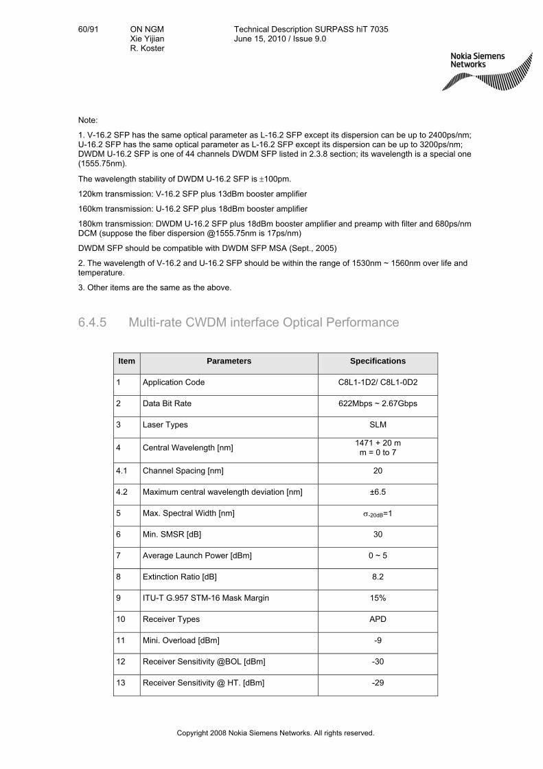
60/91 ON NGM Xie Yijian R. Koster
Technical Description SURPASS hiT 7035 June 15, 2010 / Issue 9.0
Copyright 2008 Nokia Siemens Networks. All rights reserved.
Note:
1. V-16.2 SFP has the same optical parameter as L-16.2 SFP except its dispersion can be up to 2400ps/nm; U-16.2 SFP has the same optical parameter as L-16.2 SFP except its dispersion can be up to 3200ps/nm; DWDM U-16.2 SFP is one of 44 channels DWDM SFP listed in 2.3.8 section; its wavelength is a special one (1555.75nm).
The wavelength stability of DWDM U-16.2 SFP is 100pm.
120km transmission: V-16.2 SFP plus 13dBm booster amplifier
160km transmission: U-16.2 SFP plus 18dBm booster amplifier
180km transmission: DWDM U-16.2 SFP plus 18dBm booster amplifier and preamp with filter and 680ps/nm DCM (suppose the fiber dispersion @1555.75nm is 17ps/nm)
DWDM SFP should be compatible with DWDM SFP MSA (Sept., 2005)
2. The wavelength of V-16.2 and U-16.2 SFP should be within the range of 1530nm ~ 1560nm over life and temperature.
3. Other items are the same as the above.
6.4.5 Multi-rate CWDM interface Optical Performance
Item Parameters Specifications
1 Application Code C8L1-1D2/ C8L1-0D2
2 Data Bit Rate 622Mbps ~ 2.67Gbps
3 Laser Types SLM
4 Central Wavelength [nm] 1471 + 20 m m = 0 to 7
4.1 Channel Spacing [nm] 20
4.2 Maximum central wavelength deviation [nm] ±6.5
5 Max. Spectral Width [nm] -20dB=1
6 Min. SMSR [dB] 30
7 Average Launch Power [dBm] 0 ~ 5
8 Extinction Ratio [dB] 8.2
9 ITU-T G.957 STM-16 Mask Margin 15%
10 Receiver Types APD
11 Mini. Overload [dBm] -9
12 Receiver Sensitivity @BOL [dBm] -30
13 Receiver Sensitivity @ HT. [dBm] -29
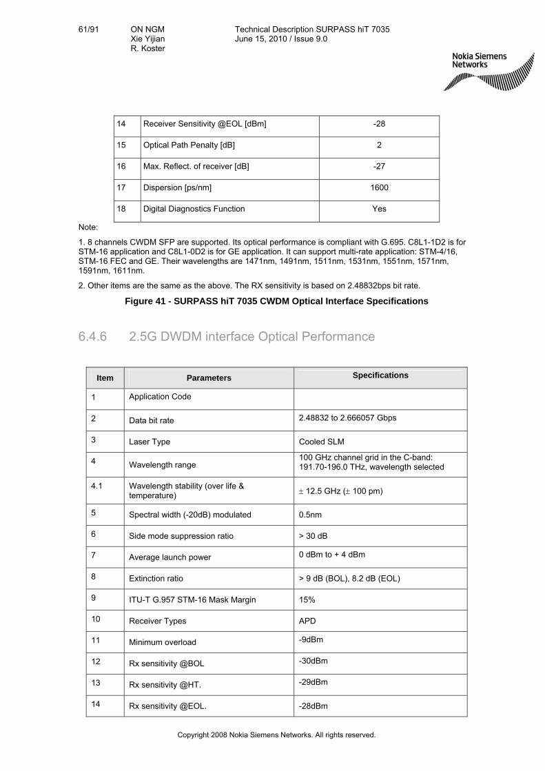
61/91 ON NGM Xie Yijian R. Koster
Technical Description SURPASS hiT 7035 June 15, 2010 / Issue 9.0
Copyright 2008 Nokia Siemens Networks. All rights reserved.
14 Receiver Sensitivity @EOL [dBm] -28
15 Optical Path Penalty [dB] 2
16 Max. Reflect. of receiver [dB] -27
17 Dispersion [ps/nm] 1600
18 Digital Diagnostics Function Yes
Note:
1. 8 channels CWDM SFP are supported. Its optical performance is compliant with G.695. C8L1-1D2 is for STM-16 application and C8L1-0D2 is for GE application. It can support multi-rate application: STM-4/16, STM-16 FEC and GE. Their wavelengths are 1471nm, 1491nm, 1511nm, 1531nm, 1551nm, 1571nm, 1591nm, 1611nm.
2. Other items are the same as the above. The RX sensitivity is based on 2.48832bps bit rate.
Figure 41 - SURPASS hiT 7035 CWDM Optical Interface Specifications
6.4.6 2.5G DWDM interface Optical Performance
Item Parameters Specifications
1 Application Code
2 Data bit rate 2.48832 to 2.666057 Gbps
3 Laser Type Cooled SLM
4 Wavelength range 100 GHz channel grid in the C-band: 191.70-196.0 THz, wavelength selected
4.1 Wavelength stability (over life & temperature) 12.5 GHz ( 100 pm)
5 Spectral width (-20dB) modulated 0.5nm
6 Side mode suppression ratio > 30 dB
7 Average launch power 0 dBm to + 4 dBm
8 Extinction ratio > 9 dB (BOL), 8.2 dB (EOL)
9 ITU-T G.957 STM-16 Mask Margin 15%
10 Receiver Types APD
11 Minimum overload -9dBm
12 Rx sensitivity @BOL -30dBm
13 Rx sensitivity @HT. -29dBm
14 Rx sensitivity @EOL. -28dBm

62/91 ON NGM Xie Yijian R. Koster
Technical Description SURPASS hiT 7035 June 15, 2010 / Issue 9.0
Copyright 2008 Nokia Siemens Networks. All rights reserved.
15 Path Penalty 3 dB
16 Receiver reflectance < -27 dB
17 Dispersion tolerance -2400 ps/nm … + 2400 ps/nm
18 Digital diagnostic function Yes
Note:
1. 44 channels DWDM SFP are supported. It can support STM-16 and STM-16 FEC application. Its channel spacing is 100GHz. Its wavelength table is as follows. DWDM SFP should be compatible with DWDM SFP MSA (Sept., 2005)
2. Please notice that 192.7THz (1555.75nm) DWDM SFP will be used for 180km ultra-long haul transmission application.
3. Other items are the same as the above.
Figure 42 - SURPASS hiT 7035 DWDM Optical Interface Specifications
ITU Channel Number
Frequency (THz)
Wavelength (nm)
ITU Channel
Number Frequency
(THz) Wavelength
(nm)
60 196.00 1529.55 38 193.8 1546.92
59 195.9 1530.33 37 193.7 1547.72
58 195.8 1531.12 36 193.6 1548.51
57 195.7 1531.90 35 193.5 1549.32
56 195.6 1532.68 34 193.4 1550.12
55 195.5 1533.47 33 193.3 1550.92
54 195.4 1534.25 32 193.2 1551.72
53 195.3 1535.04 31 193.1 1552.52
52 195.2 1535.82 30 193.0 1553.33
51 195.1 1536.61 29 192.9 1554.13
50 195.0 1537.40 28 192.8 1554.94
49 194.9 1538.19 27 192.7 1555.75
48 194.8 1538.98 26 192.6 1556.55
47 194.7 1539.77 25 192.5 1557.36
46 194.6 1540.56 24 192.4 1558.17
45 194.5 1541.35 23 192.3 1558.98
44 194.4 1542.14 22 192.2 1559.79
43 194.3 1542.94 21 192.1 1560.61
42 194.2 1543.73 20 192.0 1561.42
41 194.1 1544.53 19 191.9 1562.23
40 194.0 1545.32 18 191.8 1563.05
39 193.9 1546.12 17 191.7 1563.86
Figure 43 - SURPASS hiT 7035 DWDM Wavelenthes

63/91 ON NGM Xie Yijian R. Koster
Technical Description SURPASS hiT 7035 June 15, 2010 / Issue 9.0
Copyright 2008 Nokia Siemens Networks. All rights reserved.
6.4.7 GE Optical Transmitter and Receiver Interfaces
6.4.7.1 1000 Base-SX interface parameters
Parameter 62.5 µm MMF 50 µm MMF Unit
Laser Type Shortwave Laser -
Signal Rate 1.25 ± 100 ppm GBd
Wavelength Range 770 to 860 Nm
Trise/Tfall (max; 20%-80%;ë> 830 nm) 0.26 Ns
Trise/Tfall (max; 20%-80%;ë= 830 nm) 0.21 Ns
Maximum RMS Width 0.85 Nm
Mean Launch Power (Maximum) a) DBm
Mean Launch Power (Minimum) –9.5 DBm
Mean Launch Power when transmitter is OFF (max) b –30 DBm
Minimum Extinction Ratio 9 Db
RIN (max) –117 dB/Hz
Coupled Power Ratio (CPR) (min) c 9 < CPR dB
a. The 1000 Base-SX launch power is the lesser of the class 1 safety limit as defined by IEEE Standard 802.3 Clause 38.7.2 or the average receive power (max) defined in herein.
b. Examples of an OFF transmitter are: no power supplied to the PMD, laser shutdown for safety conditions, activation of a “transmit disable” or other optional module laser shut down conditions. During all conditions when the PMA is powered, the ac signal (data) into the transmit port will be valid encoded 8B/10B patterns (this is a requirement of the PCS layers) except for short durations during system power-on-reset or diagnostics when the PMA is placed in a loopback mode.
c. Radial overfilled launches as described in IEEE Standard 802.3 Clause 38A.2, while they may meet CPRranges, should be avoided.
Figure 44 - 1000 Base-SX transmitter interface parameters
Parameter 62.5 µm MMF 50 µm MMF Unit
Signal rate 1.25 ± 100 ppm GBd
Wavelength Range 770 to 860 Nm
Mean Receiving Power (Max.) 0 dBm
Receiving Sensitivity –17 dBm
Minimum Return Loss 12 dB
Stressed receive sensitivity a, b –12.5 –13.5 dBm
Vertical eye-closure penalty c 2.60 2.20 dB
Receive electrical 3 dB upper cutoff frequency (max) 1500 MHz
a. Measured with conformance test signal at TP3 (see IEEE Standard 802.3 Clause 38.6.11) for BER = 10–12 at the eye center.
b. Measured with a transmit signal having a 9 dB extinction ratio. If another extinction ratio is used, the stressed receive sensitivity should be corrected for the extinction ratio penalty.
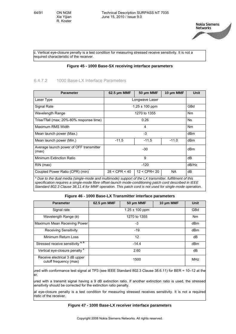
64/91 ON NGM Xie Yijian R. Koster
Technical Description SURPASS hiT 7035 June 15, 2010 / Issue 9.0
Copyright 2008 Nokia Siemens Networks. All rights reserved.
c. Vertical eye-closure penalty is a test condition for measuring stressed receive sensitivity. It is not a required characteristic of the receiver.
Figure 45 - 1000 Base-SX receiving interface parameters
6.4.7.2 1000 Base-LX Interface Parameters
Parameter 62.5 µm MMF 50 µm MMF 10 µm MMF Unit
Laser Type Longwave Laser
Signal Rate 1.25 ± 100 ppm GBd
Wavelength Range 1270 to 1355 Nm
Trise/Tfall (max; 20%-80% response time) 0.26 Ns
Maximum RMS Width 4 Nm
Mean launch power (Max.) -3 dBm
Mean launch power (Min.) -11.5 -11.5 -11.0 dBm
Average launch power of OFF transmitter (max)
-30 dBm
Minimum Extinction Ratio 9 dB
RIN (max) -120 dB/Hz
Coupled Power Ratio (CPR) (min)* 28 < CPR < 40 12 < CPR< 20 NA dB
* Due to the dual media (single-mode and multimode) support of the LX transmitter, fulfillment of this specification requires a single-mode fibre offset-launch mode-conditioning patch cord described in IEEE Standard 802.3 Clause 38.11.4 for MMF operation. This patch cord is not used for single-mode operation.
Figure 46 - 1000 Base-LX Transmitter interface parameters
Parameter 62.5 µm MMF 50 µm MMF 10 µm MMF Unit
Signal rate 1.25 ± 100 ppm GBd
Wavelength Range (ë) 1270 to 1355 Nm
Maximum Mean Receiving Power -3 dBm
Receiving Sensitivity -19 dBm
Minimum Return Loss 12 dB
Stressed receive sensitivity Pa, bP -14.4 dBm
Vertical eye-closure penalty Pc P 2.60 dB
Receive electrical 3 dB upper cutoff frequency (max)
1500 MHz
ured with conformance test signal at TP3 (see IEEE Standard 802.3 Clause 38.6.11) for BER = 10–12 at the er.
ured with a transmit signal having a 9 dB extinction ratio. If another extinction ratio is used, the stressedsensitivity should be corrected for the extinction ratio penalty.
cal eye-closure penalty is a test condition for measuring stressed receives sensitivity. It is not a requirederistic of the receiver.
Figure 47 - 1000 Base-LX receiver interface parameters

65/91 ON NGM Xie Yijian R. Koster
Technical Description SURPASS hiT 7035 June 15, 2010 / Issue 9.0
Copyright 2008 Nokia Siemens Networks. All rights reserved.
6.4.8 Electrical Interface Performances
This section provides the E1 and T1 electrical interface specifications:
1) 2,048 Kbit/s digital interface
2) Allowable bit rate deviation of 2,048 Kbit/s, and 10/100M Base-T Output Signals
3) Allowable attenuation at the 2,048 Kbit/s input port
4) Allowable frequency deviation at the 2,048 Kbit/s, and 10/100M BaseT interface
5) Anti-interference capability of the 2,048 Kbit/s input port
6.4.8.1 Electrical Interface Parameters Specification
The following table shows the parameters for the 2048 Kbit/s digital interface:
Pulse Shape (Nominally Rectangular)
All marks of a valid signal must conform to the mask irrespective of the sign. The value V corresponds to the
nominal peak value.
Pair(s) in each direction One coaxial pair
Test load impedance 75 Ohms resistive
Nominal peak voltage of a mark (pulse)
2.37 V
Peak voltage of a space (no pulse) 0 ± 0.237 V
Nominal pulse width 244 ns
Ratio of the amplitudes of positive and negative pulses at the center of the
pulse interval 0.95 to 1.05
Ratio of the widths of positive and negative pulses at the nominal half
amplitude 0.95 to 1.05
Interface Threshold Measurement Filter Bandwidth
Rate 20 Hz – 100 kHz
18 kHz – 100 kHz
Maximum peak-to-peak
jitter at an output port
2048 kbit/s 1.5 UI 0.2 UI
Figure 48 - 2048 kbit/s Electrical Interface Parameters
6.4.8.2 Allowable Bit Rate Deviation of Output Signals
Allowable Bit Rate Deviation of Output Signals is the difference between the actual signal bit rate and the nominal bit rate measured under AIS output condition. SURPASS

66/91 ON NGM Xie Yijian R. Koster
Technical Description SURPASS hiT 7035 June 15, 2010 / Issue 9.0
Copyright 2008 Nokia Siemens Networks. All rights reserved.
hiT 7035 meets the standard requirements of output signal allowable bit rate deviation as shown in table below:
Electrical Interface Types Standard Requirements (ppm)
2048 kbit/s ±50
10/100M Base-T ±100
Figure 49 - Electrical Interface Output Signals Bit Rate Allowable Deviation
6.4.8.3 Allowable Attenuation at the Input Port
SURPASS hiT 7035 meets the standard requirements for the allowable attenuation at the input port:
Electrical Interface Types Standard Requirements (dB)
2048 kbit/s 0 ~ 6
34 368 kbit/s
860 to 1720 kHz
1720 to 34 368 kHz
34 368 to 51 550 kHz
155 520 kbit/s 0 ~ 12.8
Figure 50 - Electrical Interface Allowable Input Attenuation
6.4.8.4 Allowable Frequency Deviation at the Input Port
Allowable input signals frequency deviation is the signal bit rate variation range that the system can tolerate. The following table shows the standard requirements for the allowable frequency deviation at the input port:
Electrical Interface Types Standard Requirements (ppm)
2048 kbit/s ±50
10/100M Base-T ±100
Figure 51 - Electrical Interface Allowable Input Port Frequency Deviation
6.4.8.5 Anti-interference Capability of the Input Port
SURPASS hiT 7035 meets the standard requirements for the anti-interference capability of the input port:

67/91 ON NGM Xie Yijian R. Koster
Technical Description SURPASS hiT 7035 June 15, 2010 / Issue 9.0
Copyright 2008 Nokia Siemens Networks. All rights reserved.
Electrical Interface Types Standard Requirements (dB)
2048 kbit/s 18
155 520 kbit/s ≥15
Figure 52 - Electrical Interface Input Port Anti-interference Capability
6.4.9 Timing and Synchronization Performance
6.4.9.1 Output Jitter
The following table shows the maximum acceptable level of network output jitter for the timing (synchronization) interface:
Output Interface Measuring band (-3dB frequencies)
Peak-to-peak Amplitude (UIpp)
PRC 20 ~ 100 K 0.05 UI
SSU 20 ~ 100 K 0.05 UI
20 ~ 100 K 0.5 UI SEC
49 ~ 100 K 0.2 UI
20 ~ 100 K 1.5 UI SECPDH Synchronization (2048 kbit/s)
18 ~ 100 K 0.2 UI
Figure 53 - Timing Output Jitter
6.4.9.2 Internal Timing Source Output Frequency
The following table shows the output accuracy of the timing interface in its free-run mode:
Timing Interface Standard requirement (ppm)
System Clock ± 0.5
Figure 54 - Internal Timing Source Output Frequency
6.4.10 Jitter Performance
Jitter and wander tolerance, transfer, and production specifications comply with the ITU- T Recommendations G.783, G.813 Option 1, G.823, G.824, G.825, and G.958, the China MII standard YD/T 1146-2001 and ETSI standards.
6.4.11 STM-N Interface Output Jitter

68/91 ON NGM Xie Yijian R. Koster
Technical Description SURPASS hiT 7035 June 15, 2010 / Issue 9.0
Copyright 2008 Nokia Siemens Networks. All rights reserved.
The following table shows the maximum acceptable level of output jitter at any STM-N output within a digital network (measured of a 60 second interval):
Interface Measuring band
(-3dB frequencies) Peak-to-peak Amplitude (UIpp)
500 Hz ~ 1.3 MHz 1.50 UI STM-1 (Optical)
65 KHz ~ 1.3 MHz 0.15 UI
500 Hz ~ 1.3 MHz 1.50 UI STM-1 (Electrical)
65 KHz ~ 1.3 MHz 0.075 UI
1000 Hz ~ 5 MHz 1.50 UI STM-4 (Optical)
250 KHz ~ 5 MHz 0.15 UI
5000 Hz ~ 20 MHz 1.50 UI STM-16 (Optical)
1 MHz ~ 20 MHz 0.15 UI
Figure 55 - STM-1/-4/-16 Interface Output Jitter
6.4.11.1 STM-N and PDH Input Interface Jitter Tolerance
The following tables show the input jitter tolerance for the STM-N interfaces:
Interface Frequency (Hz) Peak-to-Peak Jitter Amplitude
10 < f <= 19.3 38.9 UI (.25 us)
19.3 < f <= 68.7 750 f -1 UI
68.7 < f <= 500 750 f -1 UI
500 < f <= 6.5 k 1.5 UI
6.5 k < f <= 65k 9.8 x 10³ f -1 UI
STM-1 (Optical)
65 k < f <= 1.3 M 0.15 UI
10 < f <= 19.3 38.9 UI (.25 us)
19.3 < f <= 500 750 f -1 UI
500 < f <= 3.3 k 1.5 UI
3.3 k < f <= 65 k 4.9 x 10³ f -1 UI
STM-1 (Electrical)
65 k < f <= 1.3 M 0.075 UI
Figure 56 - STM-1 Interface Jitter Tolerance

69/91 ON NGM Xie Yijian R. Koster
Technical Description SURPASS hiT 7035 June 15, 2010 / Issue 9.0
Copyright 2008 Nokia Siemens Networks. All rights reserved.
Interface Frequency (Hz) Peak-to-Peak Jitter Amplitude
9.65 < f <= 100 1500 f -1 UI
100 < f <= 1000 1500 f -1 UI
1 k < f <= 25 k 1.5 UI
25 k < f <= 250 k 3.8 x 10⁴ f -1 UI
STM-4 (Optical)
250 k < f <= 5 M 0.15 UI
Figure 57 - STM-4 Interface Jitter Tolerance
Interface Frequency (Hz) Peak-to-Peak Jitter Amplitude
10 < f <= 12.1 622 UI
12.1 < f <= 500 7500 f -1 UI
500 < f <= 5 k 7500 f -1 UI
5 k < f <= 100 k 1.5 UI
STM-16 (Optical)
100 k < f <= 1 M 1.5 x 10⁵ f -1 P UI
Figure 58 - STM-16 Interface Jitter Tolerance
Maximum Peak-to-Peak Jitter Filter Characteristics
Mapping G.703 (PDH)
Interface f1 High pass
f3 High pass
f4 Low pass
f1-f4 f3-f4
1 544 Kbit/s 10 Hz
20 dB/dec 8 kHz
40 kHz –20 dB/dec
0.7 (A0)
2 048 Kbit/s 20 Hz
20 dB/dec
18 kHz (700 Hz)
20 dB/dec
100 kHz –60 dB/dec
0.075 UI
34 368 Kbit/s 100 Hz
20 dB/dec 10 kHz
20 dB/dec 800 kHz
–60 dB/dec 0.075 UI
44 736 Kbit/s 10 Hz 30 kHz 400 kHz
–20 dB/dec 0.40 UI (A0)
139 264 Kbit/s 200 Hz
20 dB/dec 10 kHz
20 dB/dec 3 500 kHz
–60 dB/dec 0.075 UI
Figure 59 - PDH mapping jitter generation specification

70/91 ON NGM Xie Yijian R. Koster
Technical Description SURPASS hiT 7035 June 15, 2010 / Issue 9.0
Copyright 2008 Nokia Siemens Networks. All rights reserved.
Maximum Peak-Peak Jitter Filter Characteristics
Combined G.703 (PDH) Interface
f1 high pass
f3 high pass
f4 low pass
f1-f4 f3-f4
1 544 Kbit/s 10 Hz
20 dB/dec 8 kHz
40 kHz –20 dB/dec
2 048 Kbit/s 20 Hz
20 dB/dec
18 kHz (700 Hz)
20 dB/dec
100 kHz –60 dB/dec
0.4 UI
0.075 UI
34 368 Kbit/s 100 Hz
20 dB/dec 10 kHz
20 dB/dec 800 kHz
–60 dB/dec
0.4 UI 0.75 UI
0.075 UI
Figure 60 - SURPASS hiT 7035 PDH interface combined jitter generation spec
6.5 Timing
SURPASS hiT 7035 provides the following timing clock interfaces:
External clock source (T3): 2 input port, 2048kbit/s (G.703-6) or 2048 kHz (G.703-10)75
Synchronize output (T4): 2 output port, 2048kbit/s (G.703)75
SURPASS hiT 7035supports the selection of the following 4 timing references:
Line/tributary timing (STM-1/-4/-16 lines, or E1 tributary)
External station clock timing
Internal clock (ITU-T G.813 option 1)
E1 tributary timing (any E1 port can be selected as the timing source)
Additionally, SURPASS hiT 7035 is able to provide retiming for E1 (2Mbit/s) traffic interfaces to provide synchronized reference to another equipment.
6.6 Power Source
6.6.1 Power Supply
SURPASS hiT 7035 supports -48V/60V (-40.5~-72.0 V) DC power supply, support load balanced 1+1 power supply modular protection.

71/91 ON NGM Xie Yijian R. Koster
Technical Description SURPASS hiT 7035 June 15, 2010 / Issue 9.0
Copyright 2008 Nokia Siemens Networks. All rights reserved.
6.6.2 Power Consumption
Maximum power consumption: 250W (Full Configuration)
Average power consumption: 163W (Typical Configuration)
6.6.3 Cooling
The equipment is assembled with one fan unit. It is field replaceable. Fan failure does not affect service.
6.6.4 Mechanical Structure
SURPASS hiT 7035 chassis mechanical parameters:
Height: 486mm (11U)
Width: 403mm
Depth: 240mm (300 mm back-to-door)
SURPASS hiT 7035 can be installed in the following types of racks:
EIA 310 19”
2200mm(Height) 600mm (Width) 300mm (Depth)
2600mm(Height)×600mm(Width)×300mm(Depth)
Depending on the electrical cable load you can install up to three SURPASS hiT 7035 chassis into a 2200mm high ETSI rack or an EIA 310 19” rack ( typically two systems per rack ).
6.7 Environment Requirements
SURPASS hiT 7035 system is designed to comply with the following ETSI requirements (ETS 300 019) on environmental conditions:
ETSI Class 3.2 on Environment
ETSI Class 1.2 on Storage
ETSI Class 2.3 on Transportation
The environmental conditions required by SURPASS hiT 7035 are as follows:

72/91 ON NGM Xie Yijian R. Koster
Technical Description SURPASS hiT 7035 June 15, 2010 / Issue 9.0
Copyright 2008 Nokia Siemens Networks. All rights reserved.
Environmental Condition Temperature Relative Humidity
Transport and storage -20º ~ 60ºC 2% ~ 98%
Operation for long term -5º ~ 45ºC 5% ~ 90% (30ºC)
Operation for short term -10º ~ 50ºC 5% ~ 90% (30ºC)
Figure 61 - SURPASS hiT 7035 Environment Requirements
6.7.1 Enhanced Temperature Variant
Depending on the used chassis variant of SURPASS hiT 7035 also an operating temperature up to 55 degree is available.
This enhanced temperature variant has a more powerful fan assembly and is introduced with system software R4.3.
Performance Guaranteed:
Operation for long term: -5°C~55°C
Relative Humidity: 10%~100% (30°C)
6.8 Electromagnetic Compatibility
SURPASS hiT 7035 meets the present customer oncoming mandatory requirements
Of ETSI EN 300 386 v1.4.1, which is based on EN 55022 (emission) and EN 61000-4-x series (immunity)
Emission (EN 55022)
Radiated emission EN 55022, Class A
Conducted emission EN 55022, Class A
DC power port EN 55022, Class A
Signal ports EN 55022, Class A
Immunity (EN 61000-4-x series)
Electrostatic Discharge EN 61000-4-2, level 2
Radiated immunity EN 61000-4-3, level 2 & level 3
Electrical fast transients EN 61000-4-4
DC power port EN 61000-4-4, level 1
Signal ports EN 61000-4-4, level 1
Surges EN 61000-4-5
Indoor signal ports EN 61000-4-5, level 1
Continuous wave EN 61000-4-6
All ports (telecom ports, AC, DC) EN 61000-4-6, level 2
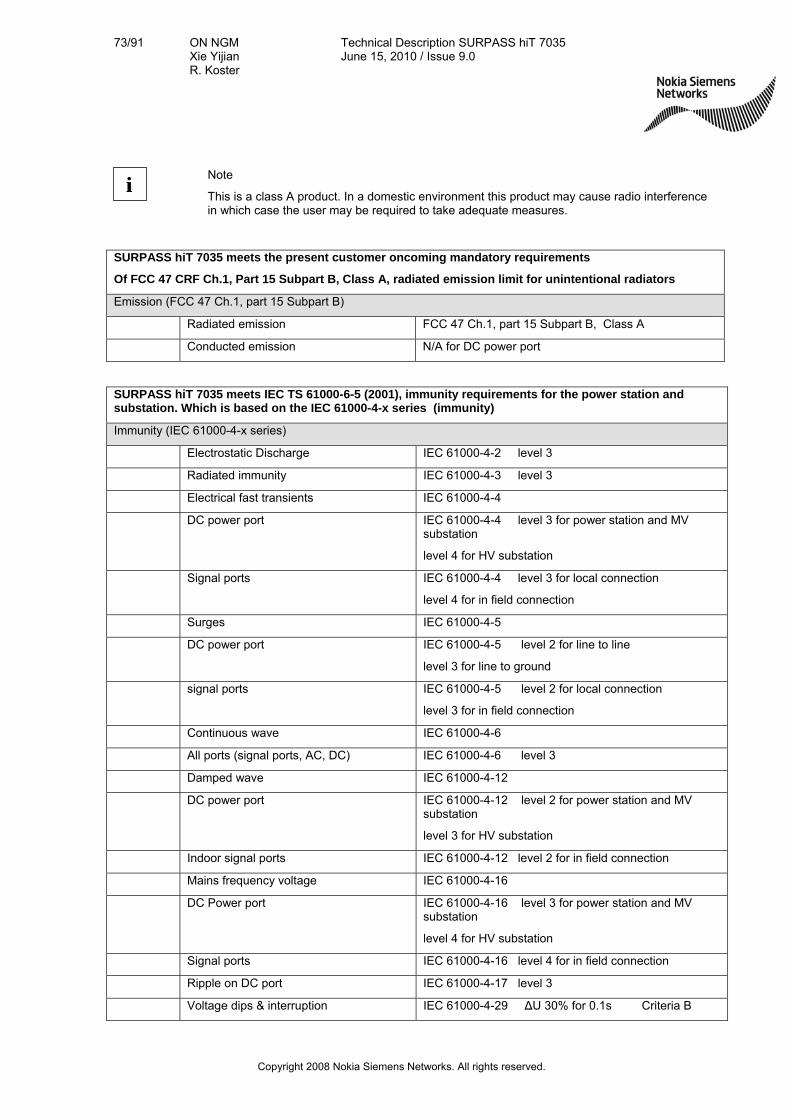
73/91 ON NGM Xie Yijian R. Koster
Technical Description SURPASS hiT 7035 June 15, 2010 / Issue 9.0
Copyright 2008 Nokia Siemens Networks. All rights reserved.
ii
Note
This is a class A product. In a domestic environment this product may cause radio interference in which case the user may be required to take adequate measures.
SURPASS hiT 7035 meets the present customer oncoming mandatory requirements
Of FCC 47 CRF Ch.1, Part 15 Subpart B, Class A, radiated emission limit for unintentional radiators
Emission (FCC 47 Ch.1, part 15 Subpart B)
Radiated emission FCC 47 Ch.1, part 15 Subpart B, Class A
Conducted emission N/A for DC power port
SURPASS hiT 7035 meets IEC TS 61000-6-5 (2001), immunity requirements for the power station and substation. Which is based on the IEC 61000-4-x series (immunity)
Immunity (IEC 61000-4-x series)
Electrostatic Discharge IEC 61000-4-2 level 3
Radiated immunity IEC 61000-4-3 level 3
Electrical fast transients IEC 61000-4-4
DC power port IEC 61000-4-4 level 3 for power station and MV substation
level 4 for HV substation
Signal ports IEC 61000-4-4 level 3 for local connection
level 4 for in field connection
Surges IEC 61000-4-5
DC power port IEC 61000-4-5 level 2 for line to line
level 3 for line to ground
signal ports IEC 61000-4-5 level 2 for local connection
level 3 for in field connection
Continuous wave IEC 61000-4-6
All ports (signal ports, AC, DC) IEC 61000-4-6 level 3
Damped wave IEC 61000-4-12
DC power port IEC 61000-4-12 level 2 for power station and MV substation
level 3 for HV substation
Indoor signal ports IEC 61000-4-12 level 2 for in field connection
Mains frequency voltage IEC 61000-4-16
DC Power port IEC 61000-4-16 level 3 for power station and MV substation
level 4 for HV substation
Signal ports IEC 61000-4-16 level 4 for in field connection
Ripple on DC port IEC 61000-4-17 level 3
Voltage dips & interruption IEC 61000-4-29 ΔU 30% for 0.1s Criteria B

74/91 ON NGM Xie Yijian R. Koster
Technical Description SURPASS hiT 7035 June 15, 2010 / Issue 9.0
Copyright 2008 Nokia Siemens Networks. All rights reserved.
ΔU 60% for 0.1s
ΔU 100% for 0.05s
SURPASS hiT 7035 meets IEC 61000-6-2 : 2005, immunity requirement for industry environment. Which is based on the IEC 61000-4-x series (immunity)
Immunity (IEC 61000-4-x series)
Electrostatic Discharge IEC 61000-4-2 level 2 and level 3
Radiated immunity IEC 61000-4-3 level 1, level 2 and level 3
Electrical fast transients IEC 61000-4-4
DC power port IEC 61000-4-4 level 3
Signal ports IEC 61000-4-4 level 2
Surges IEC 61000-4-5
DC power port IEC 61000-4-5 level 1
signal ports IEC 61000-4-5 level 2
Continuous wave IEC 61000-4-6
All ports (signal ports, AC, DC) IEC 61000-4-6 level 3
6.9 Vibration Tests
6.9.1 Shipping Test
SURPASS hiT 7035 meets the following shipping test standards.
Test Test Standard
Amplitude (>= 0.6 mm) ETSI
Acceleration (>= 15 m/s—X, Y, Z three directions) ETSI
Test time (>=3 hours) ETSI
Figure 62 - Shipping Test Standards
6.9.2 Office Test
SURPASS hiT 7035 meets the following office test standards.
Test Test Standard
Amplitude (>= 0.6 mm) ETSI
Acceleration (>= 15 m/s—X, Y, Z three directions) ETSI
Test time (>= 3 hours) ETSI
75/91 ON NGM Xie Yijian R. Koster
Technical Description SURPASS hiT 7035 June 15, 2010 / Issue 9.0
Copyright 2008 Nokia Siemens Networks. All rights reserved.
Figure 63 - Office test standards
6.10 Alarms and Events
6.10.1 Alarm Types
There are five types of failure in the system:
Communication Failure: Failures related to communication status (such as LOS, LOF, AIS, DEG and LAN) or other communication protocol related failures (such as, STMfLOS).
Quality of Service Failure: Failure related to system performance, such as responding time too long, threshold crossing, and performance degrading.
Equipment Failure: Failures related to the hardware equipment, such as power system defect, timing interface failures, processor defect, transmit/receiver equipment defect or any other equipment component faults (such as, EQfFLT).
Processing Error Failure: Failures related to the software, memory overflow, version incompatibility, software errors, program illegal interruption, NE configuration errors and NE inaccessible.
Environmental Failure: Failures related to environment changes, such as unacceptable temperature and humidity, ventilation or cooling system faults, excessive vibration, and door open/close.
6.10.2 Alarm Severity Level
There are five alarm severity levels defined in the system:
Critical—Service-interrupting alarms.
Major—Service-affecting alarms.
Minor—Non-Service-affecting alarms, but can potentially become service-affecting alarms. You need to perform fault inspection and any necessary fixes to prevent it from becoming worse.
Warning—Non-Service-affecting, information presented to the operator for the purpose of maintenance.
Indeterminate—The alarm severity level is undefined.
The system has a red LED alarm indicator for Prompt (service-affecting) and a yellow LED alarm indicator for Deferred/Info (non-service-affecting).
6.10.3 Alarm Reports

76/91 ON NGM Xie Yijian R. Koster
Technical Description SURPASS hiT 7035 June 15, 2010 / Issue 9.0
Copyright 2008 Nokia Siemens Networks. All rights reserved.
The Element Management software logs the 10,000 latest failures in the alarm log and independently reports the failure status change to the EMS. SURPASS hiT 7035 allows users to query alarm logs using a variety of criteria.
6.10.4 Events
There are three types of events defined in the system: Management, Hardware, and Software. SURPASS hiT 7035 requires every event to be time-stamped.
An Event (as defined by ITU-T Recommendation M.2410) is an instantaneous occurrence that changes the global status of an object. This status change may be persistent or temporary, allowing for surveillance, monitoring, and performance measurement functionality, etc. Events may or may not generate reports; they may be spontaneous or planned; they may trigger other events or may be triggered by one or more other events. (Recommendation M.60)
6.10.4.1 Management Events
The attributes of the management events include: Event name, Timestamp, User name and privilege level, and Description.
Name Description
User login Identifies the user that has just logged in.
User logout Identifies the user that has just logged out.
User auto-logout due to timeout Identifies the user that was just logged out by the system
because of inactivity.
User password change The password of a user account has been changed.
Unauthorized login attempt A user has attempted and failed to log in.
Alarm log cleared A user has cleared out the alarm log file.
Event log cleared A user has cleared out the event log file.
Figure 64 - Management Events
6.10.4.2 Hardware Events The object (located as precisely as possible) that generates the event is also reported.
Name Description
Auto acceptance A module of a different type from the previous module was installed and booted.
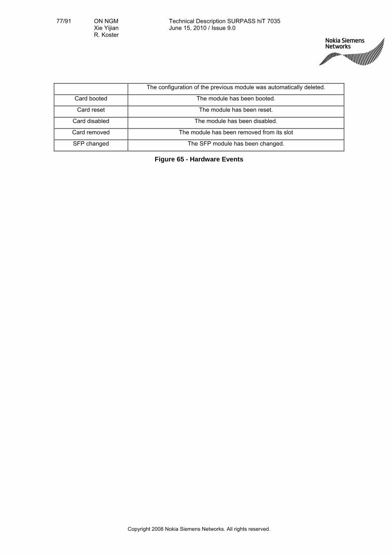
77/91 ON NGM Xie Yijian R. Koster
Technical Description SURPASS hiT 7035 June 15, 2010 / Issue 9.0
Copyright 2008 Nokia Siemens Networks. All rights reserved.
The configuration of the previous module was automatically deleted.
Card booted The module has been booted.
Card reset The module has been reset.
Card disabled The module has been disabled.
Card removed The module has been removed from its slot
SFP changed The SFP module has been changed.
Figure 65 - Hardware Events

78/91 ON NGM Xie Yijian R. Koster
Technical Description SURPASS hiT 7035 June 15, 2010 / Issue 9.0
Copyright 2008 Nokia Siemens Networks. All rights reserved.
6.10.4.3 Software Events
Some of these types of software events may never happen on a certain products.
Name Description
Protection switch completed The protection switch occurred and was completed. (It applies to all
types of protection schemes. The protection group is identified.)
Protection switch back completed The protection group switched from the protection state to the normal
state. (It applies to all types of protection schemes. The protection group is identified.)
Software download started Software files are being downloaded to the backup storage place
through FTP.
Software download completed Software files are successfully downloaded to the backup storage place
through FTP.
Software upgrade started The software files in the backup storage place have started to be
activated.
Software upgrade completed A software upgrade has completed.
MIB upload started The MIB files in the backup place are being uploaded to a server
through FTP.
MIB upload completed The MIB files in the backup place are successfully uploaded through
FTP.
MIB download started The MIB files are being downloaded from a server to the MIB backup
place through FTP.
MIB download completed The MIB files are successfully downloaded from a server to the MIB
backup place through FTP.
MIB backup started The active MIB files are being backed up.
MIB backup completed The active MIB files are backed up.
MIB restore started The MIB files in the backup are being restored to active MIB files.
MIB restore completed The MIB restoration has successfully completed.
System reset The system is resetting.
System start The system is starting up.
Timing configuration changed One or more timing sources/references changed.
Port administratively down A port has been administratively set to down.
Port administratively up A port has been administratively set to up.
Figure 66 - Software Events

79/91 ON NGM Xie Yijian R. Koster
Technical Description SURPASS hiT 7035 June 15, 2010 / Issue 9.0
Copyright 2008 Nokia Siemens Networks. All rights reserved.
7. Standard Compliance
The design of the SURPASS hiT 7035 system is based on the following documents:
ITU-T G.691 Optical interfaces for single channel STM-64 and other SDH systems with optical amplifiers
G.692 Optical interfaces for multichannel systems with optical amplifiers
G.703 Physical / electrical characteristics of hierarchical digital interfaces
G.7041/Y.1303 Generic Framing Procedure
G.7042/Y.1305 Link Capacity Adjustment Schema (LCAS) for virtual concatenated sig nals
G.707 Synchronous digital hierarchy (SDH) bit rates
G.708 Network node interface for the synchronous digital hierarchy (SDH)
G.709 Synchronous multiplexing structure
G.773 Protocol suites for Q interfaces for management of transmission systems
G.781 Structure of recommendations on SDH multiplexing equipment
G.783 Characteristics of synchronous digital hierarchy multiplexing equipment functional blocks
G.784 SDH management
G.803 Architecture of transport networks based on the synchronous digital hierarchy
G.811 Timing requirements for the plesiochronous digital hierarchy (PDH)
G.813 Timing characteristics of slave clocks suitable for operation of SDH equipment
G.823 The Control of Jitter and Wander within Digital Networks which are based on the 2048 kbps Hierarchy
G.824 The control of jitter and wander within digital networks which are based on the 1544 kbit/s hierarchy
G.825 The Control of Jitter and Wander within Digital Networks which are based on the Synchronous Digital Hierarchy
G.841 Types and characteristics of SDH network protection Architectures
G.842 Interworking of SDH network protection architectures
G.957 Optical interfaces for equipment and systems relating to SDH
G.692 Optical interfaces for multichannel systems with optical amplifiers
IEEE 802.1p Standard for Local and Metropolitan Area Networks Supplement to Media Access Control (MAC) Bridges: Traffic Class Expediting and Dynamic Multicast Filtering
802.1q IEEE Standards for Local and Metropolitan Area Networks: Virtual Bridged Local Area Networks
802.1s IEEE Standards for Local and Metropolitan Area Networks
802.1w IEEE Standard for Information Technology -Telecommunications and Information Exchange Between Systems - Local and Metropolitan Area Networks - Common Specifications - Part 3: Media Access Control (MAC) Bridges:
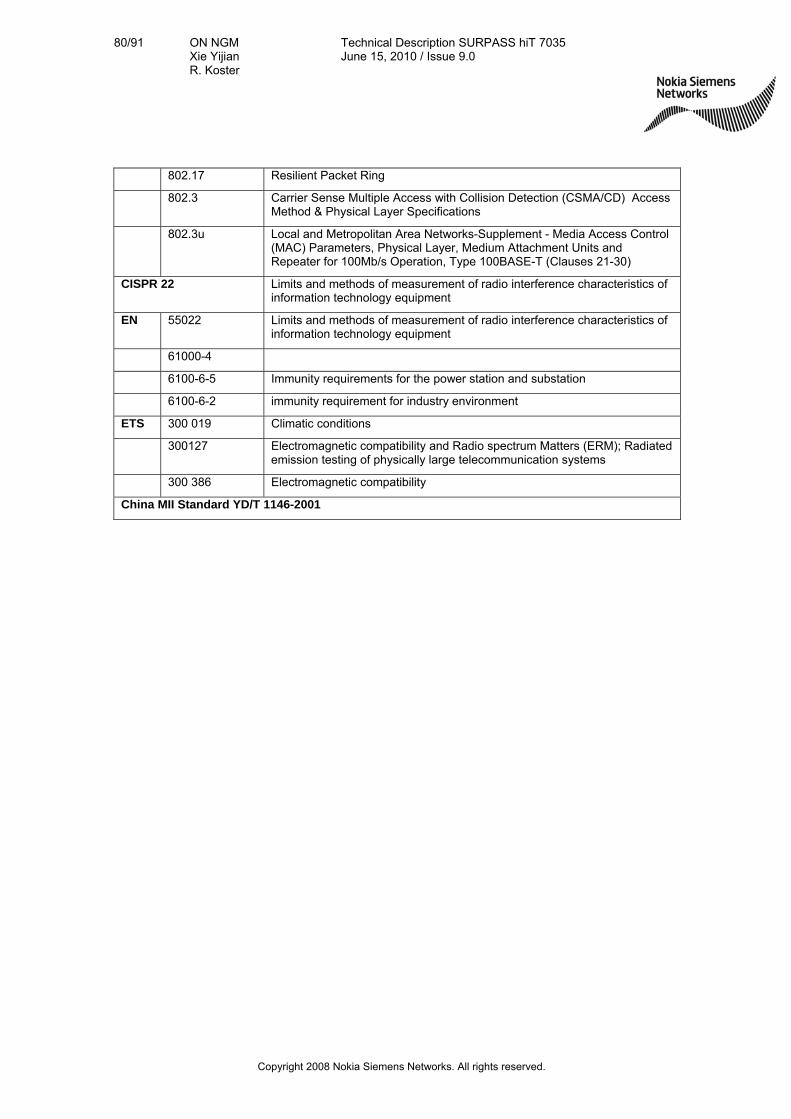
80/91 ON NGM Xie Yijian R. Koster
Technical Description SURPASS hiT 7035 June 15, 2010 / Issue 9.0
Copyright 2008 Nokia Siemens Networks. All rights reserved.
802.17 Resilient Packet Ring
802.3 Carrier Sense Multiple Access with Collision Detection (CSMA/CD) Access Method & Physical Layer Specifications
802.3u Local and Metropolitan Area Networks-Supplement - Media Access Control (MAC) Parameters, Physical Layer, Medium Attachment Units and Repeater for 100Mb/s Operation, Type 100BASE-T (Clauses 21-30)
CISPR 22 Limits and methods of measurement of radio interference characteristics of information technology equipment
EN 55022 Limits and methods of measurement of radio interference characteristics of information technology equipment
61000-4
6100-6-5 Immunity requirements for the power station and substation
6100-6-2 immunity requirement for industry environment
ETS 300 019 Climatic conditions
300127 Electromagnetic compatibility and Radio spectrum Matters (ERM); Radiated emission testing of physically large telecommunication systems
300 386 Electromagnetic compatibility
China MII Standard YD/T 1146-2001

81/91 ON NGM Xie Yijian R. Koster
Technical Description SURPASS hiT 7035 June 15, 2010 / Issue 9.0
Copyright 2008 Nokia Siemens Networks. All rights reserved.
8. Appendix 1: Definitions and Abbreviations
Abbreviation Definition
ADM Add-Drop Multiplexer
AIS Alarm Indication Signal
APS Automatic Protection Switching
ASON Automatic Switched Optical Network
ASTN Automatic Switched Transport Network
ATM Asynchronous Transfer Mode
AU Administrative Unit
AU-n Administration Unit,level n
AUG Administration Unit Group
AU-PTR Administration Unit Pointer
BA Booster Amplifier
BBE Background Block Error
BBER Background Block Error Ratio
BER Bit Error Ratio
BITS Building Integrated Timing Supply
BML Business Management Layer
BoD Bandwidth on Demand
B-RAS Broadband-Remote Access Server
(or Broadband Access Management Switch)
CDV Cell Delay Variation
CLR Cell Loss Rate
CMI Coded Mark Inversion
C-n Container- n
CORBA Common Object Request Broker ArchiTecture
CTD Cell Transfer Delay
CV Code Violation
DB Data Base
DBMS Data Base Management System
DCC Data Communications Channel
DCE Data Circuit-terminating Equipment
DCF Data Communications Function
DCN Data Communications Network
DDN Digital Data Network
DNA Distributed Network ArchiTecture
DNI Dual Node Interconnection
DNU Do Not Use for Sync.
DTE Data Terminal Equipment
DWDM Dense Wavelength-division Multiplexing

82/91 ON NGM Xie Yijian R. Koster
Technical Description SURPASS hiT 7035 June 15, 2010 / Issue 9.0
Copyright 2008 Nokia Siemens Networks. All rights reserved.
Abbreviation Definition
DXC Digital Cross Connect
ECC Embedded Control Channel
EM Element Management
EMC Electromagnetic Compatibility
EMI Electromagnetic Interference
EML Element Management Layer
EMS Element Management System
EOS Ethernet Over SDH
ES Error Second
ESD Electronic Static Discharge
ESR Error Second Ratio
ETSI European Telecommunication Standards Institute
FDM Frequency Division Multiplexing
FDDI Fiber Distributed Data Interface
FEBBE Far End Background Block Error
FEES Far End Errored Second
FESES Far End Severely Errored Second
GMPLS Generalized Multi-Protocol Label Switching
GUI Graphical User Interface
HDLC High Digital Link Control
HPC Higher order Path Connection
IP Internet Protocol
ITU-T International Telecommunication Union-Telecommunication
Standardization Sector
L2 Layer 2
LAN Local Area Network
LAPD Link Access Procedure On D-channel
LCT Local Craft Terminal
LMS Local NE Management System
LOF Loss Of Frame
LOM Loss of Multi-Frame
LOP Loss Of Pointer
LOS Loss Of Signal
LPC Lower order Path Connection
MAC Medium Access Control
MAN Metropolitan Area Network
MCU Micro Control Unit
MDI Miscellaneous Discrete Input
MDO Miscellaneous Discrete Output
MM Multi Mode
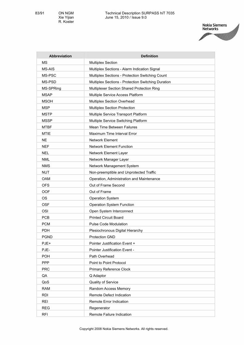
83/91 ON NGM Xie Yijian R. Koster
Technical Description SURPASS hiT 7035 June 15, 2010 / Issue 9.0
Copyright 2008 Nokia Siemens Networks. All rights reserved.
Abbreviation Definition
MS Multiplex Section
MS-AIS Multiplex Sections - Alarm Indication Signal
MS-PSC Multiplex Sections - Protection Switching Count
MS-PSD Multiplex Sections - Protection Switching Duration
MS-SPRing Multiplexer Section Shared Protection Ring
MSAP Multiple Service Access Platform
MSOH Multiplex Section Overhead
MSP Multiplex Section Protection
MSTP Multiple Service Transport Platform
MSSP Multiple Service Switching Platform
MTBF Mean Time Between Failures
MTIE Maximum Time Interval Error
NE Network Element
NEF Network Element Function
NEL Network Element Layer
NML Network Manager Layer
NMS Network Management System
NUT Non-preemptible and Unprotected Traffic
OAM Operation, Administration and Maintenance
OFS Out of Frame Second
OOF Out of Frame
OS Operation System
OSF Operation System Function
OSI Open System Interconnect
PCB Printed Circuit Board
PCM Pulse Code Modulation
PDH Plesiochronous Digital Hierarchy
PGND Protection GND
PJE+ Pointer Justification Event +
PJE- Pointer Justification Event -
POH Path Overhead
PPP Point to Point Protocol
PRC Primary Reference Clock
QA Q Adaptor
QoS Quality of Service
RAM Random Access Memory
RDI Remote Defect Indication
REI Remote Error Indication
REG Regenerator
RFI Remote Failure Indication

84/91 ON NGM Xie Yijian R. Koster
Technical Description SURPASS hiT 7035 June 15, 2010 / Issue 9.0
Copyright 2008 Nokia Siemens Networks. All rights reserved.
Abbreviation Definition
RIP Router Information Protocol
RMII Reduced Medium Independent Interface
RS Regenerator Section
RSOH Regenerator Section Overhead
SD Signal Degrade
SDH Synchronous Digital Hierarchy
SEC Station Equipment Clock
SES Severely Errored Second
SESR Severely Errored Second Ratio
SETS Synchronous Equipment Timing Source
SF Signal Failure
SFF Small Form Factor
SFP Small Form Factor Pluggable
SM Single Mode
SMCC Sub-network management control center
SML Service Management Layer
SMN SDH Management Network
SMS SDH Management Sub-Network
SMT Surface Mount Technology
SNCP Sub-network Connection Protection
SOH Section Overhead
SPRING Shared Protection Ring
SSM Synchronous State Message
STM-N Synchronous Transport Module Level-N
TCP Transport Control Protocol
TDEV Time Deviation
TDM Time Division Multiplex
TIF Telemetry Interface
TM Terminal Multiplexer
TMN Telecommunications Management Network
TU Tributary Unit
UAS Unavailable Second
VC Virtual Container
VC-n Virtual Container level n
VDN Virtual Data Network
VLAN Virtual Local Area Network
WAN Wide Area Network
WDM Wavelength Division Multiplexing
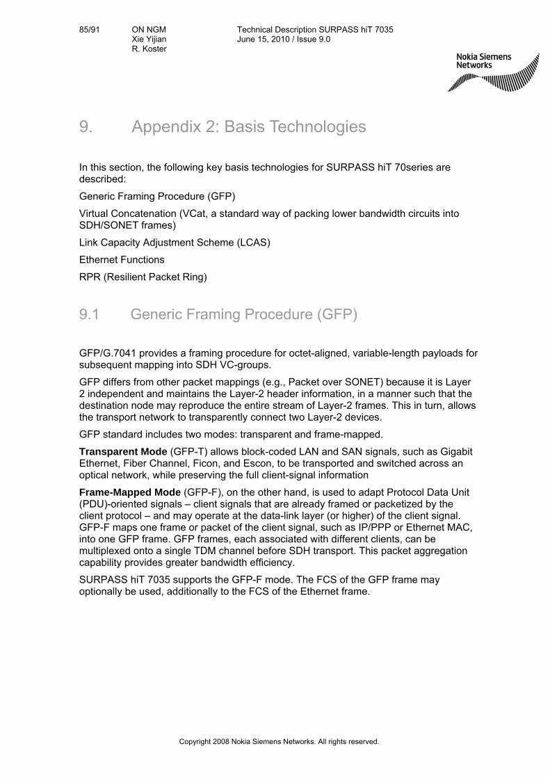
85/91 ON NGM Xie Yijian R. Koster
Technical Description SURPASS hiT 7035 June 15, 2010 / Issue 9.0
Copyright 2008 Nokia Siemens Networks. All rights reserved.
9. Appendix 2: Basis Technologies
In this section, the following key basis technologies for SURPASS hiT 70series are described:
Generic Framing Procedure (GFP)
Virtual Concatenation (VCat, a standard way of packing lower bandwidth circuits into SDH/SONET frames)
Link Capacity Adjustment Scheme (LCAS)
Ethernet Functions
RPR (Resilient Packet Ring)
9.1 Generic Framing Procedure (GFP)
GFP/G.7041 provides a framing procedure for octet-aligned, variable-length payloads for subsequent mapping into SDH VC-groups.
GFP differs from other packet mappings (e.g., Packet over SONET) because it is Layer 2 independent and maintains the Layer-2 header information, in a manner such that the destination node may reproduce the entire stream of Layer-2 frames. This in turn, allows the transport network to transparently connect two Layer-2 devices.
GFP standard includes two modes: transparent and frame-mapped.
Transparent Mode (GFP-T) allows block-coded LAN and SAN signals, such as Gigabit Ethernet, Fiber Channel, Ficon, and Escon, to be transported and switched across an optical network, while preserving the full client-signal information
Frame-Mapped Mode (GFP-F), on the other hand, is used to adapt Protocol Data Unit (PDU)-oriented signals – client signals that are already framed or packetized by the client protocol – and may operate at the data-link layer (or higher) of the client signal. GFP-F maps one frame or packet of the client signal, such as IP/PPP or Ethernet MAC, into one GFP frame. GFP frames, each associated with different clients, can be multiplexed onto a single TDM channel before SDH transport. This packet aggregation capability provides greater bandwidth efficiency.
SURPASS hiT 7035 supports the GFP-F mode. The FCS of the GFP frame may optionally be used, additionally to the FCS of the Ethernet frame.

86/91 ON NGM Xie Yijian R. Koster
Technical Description SURPASS hiT 7035 June 15, 2010 / Issue 9.0
Copyright 2008 Nokia Siemens Networks. All rights reserved.
VCOverhead VC Payload
GFP Frame
Preamble SFD control0x11 DA 6-bytes SA 6-bytes T/L 2-bytes Payload CRC 4-bytesEthernet Packet
PLI 2-bytes HEC 2 byte type 2-bytes HEC 2byte GFP Ex Payload FCS 4-bytes
Core Header Payload Header
Variable 4-65535 Byte
GFP Frame
SDH Frame
Figure 67 - GFP mapping
Benefits of GFP
The key benefits of GFP are the uniform mechanism to support all L2 protocols and high encapsulation efficiency. This provides convergence of next-generation services with existing infrastructure investment to provide network consolidation and cost savings. GFP provides:
Uniform and deterministic mapping of packet and future services to SDH/SONET transport protocols which is more robust frame delineation than flag-based mechanisms such as HDLC.
Efficient network resource utilization via GFP’s low overhead characteristics, and compatibility with virtual-concatenation processing
Flexibility of Extension Headers: This allows topology application specific fields to be defined without affecting frame delineation functions
Payload independent frame expansion, and therefore no byte stuffing.
Greater bandwidth efficiency through GFP-F frame-mode’s support for packet-level multiplexing, which allows aggregation of multiple client streams into a single TDM channel
The ability to identify the encapsulated client protocol separately from the Extension Header. This could be used to allow frame forwarding based on Extension Header fields without requiring recognition of the encapsulated client protocol.
GFP provides the interworking condition among different vendors, which is not so easy to obtain with other alternatives of the Ethernet over SDH, like PPP. The following table provides with a comparison between the two methods.

87/91 ON NGM Xie Yijian R. Koster
Technical Description SURPASS hiT 7035 June 15, 2010 / Issue 9.0
Copyright 2008 Nokia Siemens Networks. All rights reserved.
GFP Multilink PPP, PPP
Support of topologies Point to point, ring and linear Point to point
Frame delineation No need for specific frame flags, using the relationship between the PLI and cHEC to delineate frames. More stable.
Specific frame flags (opening/closing flags) are needed.
Bit/Byte stuffing No Mandatory
Class of Service
Yes, GFP frame contains data priority bits which supports for congestion control Not supported
Extendibility Excellent Not supported
Mapping method Framed, Transparent Mapped Framed
Jumbo frame support No limitation on the frame length Not supported
Figure 68 - Comparison between GFP and PPP
9.2 Virtual Concatenation (VCat)
In order to transport payloads exceeding the payload capacity of the standard set of Virtual Container Group (VC-Group), Virtual Concatenation was defined. There are two types of concatenations defined in ITU standards: contiguous and virtual concatenation.
Contiguous concatenation has been part of SDH from its early days. It was conceived to accommodate high-speed data applications that use protocols such as ATM. The ITU G.707 defined contiguously concatenated containers only to support certain rates including: STM-4c, STM-16c and STM-64c.
The basic idea of virtual concatenation (VCat) acc. to ITU-T 707 is to create a finer granularity of payloads than contiguous concatenation can offer. In addition, some legacy SDH equipment may not support contiguous concatenation transport switching, and virtually concatenated traffic is transported as individual VC-groups across the SDH network and recombined at the destination node. Carriers can map any arbitrary bandwidth to a corresponding and appropriate number of VC-12 or VC-3 or VC-4 channels. The benefits of VCat are:
Efficiency: little bandwidth is wasted and carriers now have a more efficient scenario for carrying data over the SDH network.
Compatibility: Virtual concatenation works across legacy networks. Only the end nodes of the network need to be aware of the virtually concatenated containers.
Intermediate SDH nodes forward the single Containers transparently throughout the network. Hence, with virtual concatenation, such channels can be routed over legacy networks that do not support contiguous channels.
Reliability: Virtual Concatenation, along with LCAS, allows new and efficient shared protection mechanism.

88/91 ON NGM Xie Yijian R. Koster
Technical Description SURPASS hiT 7035 June 15, 2010 / Issue 9.0
Copyright 2008 Nokia Siemens Networks. All rights reserved.
9.3 Link Capacity Adjustment Scheme (LCAS)
LCAS (ITU-T Recommendation G.7042/Y.1305, approved by the ITU-T in November 2001) is a protocol to synchronize the re-sizing of a virtual concatenation group in use, so it can be changed without corrupting packets in the process. LCAS provides automatic recovery of a link after member failures.
LCAS builds on Virtual Concatenation. While the virtual concatenation is a simple labeling of individual VC members within a virtual concatenation group, LCAS is a two-way signaling protocol that runs continuously between the two ends of the pipe and ensures that commands from the network management system to alter the pipe capacity do not impair the user’s traffic. LCAS adds several highly significant features to SDH’s capabilities:
The combination of VCat and LCAS creates fine-tuned and variable capacity SDH pipes to match the needs of packet data QOS (quality of service) and customer SLAs (service-level agreements) – and to boost carriers’ traffic-handling scalability and efficiency. LCAS allows adjustment of the size of a virtually concatenated group of channels.
The combination of VCat and LCAS can also provide soft protection schemes. Using VCat, traffic is distributively mapped into several SDH containers (e.g. VC-12s) and sent by different paths. When certain VC-12s in the same VC group fail, LCAS can delete the failed VCs from the group. The traffic can then be dynamically adapted to the rest of the VC12s bandwidth for transmission. Otherwise – without LCAS - a failure in one path of a channel built up of diversely routed paths would lead to loss of all the traffic.
9.4 Ethernet Functions and Services
Layer 2 Ethernet functions implemented in state-of-the-art transport system may include the following:
Layer 2 aggregation
Layer 2 switching
802.1p QoS/CoS based on Ethernet port and/or VLAN
Rapid Spanning Tree Protocol (RSTP) to provide Layer 2 traffic protection
Rate limiting function per port and policing per Port or per VLAN basis, the maximum allowable rate per port or per VLAN is user provisionable.
VLAN function
Ethernet Shared Ring (ESR): Layer 2 switch and Aggregator cards: all the traffic goes through the shared ring.
Ethernet / (virtual) Private Line / Ethernet Private-Line (EpL)
Ethernet (virtual) LAN (EvLAN) / Ethernet-LAN (ELAN)
Port Cross Connection and Por+VLAN Cross Connection
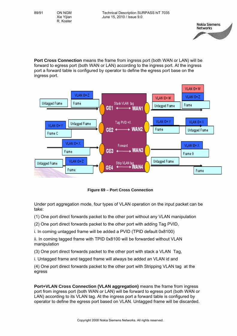
89/91 ON NGM Xie Yijian R. Koster
Technical Description SURPASS hiT 7035 June 15, 2010 / Issue 9.0
Copyright 2008 Nokia Siemens Networks. All rights reserved.
Port Cross Connection means the frame from ingress port (both WAN or LAN) will be forward to egress port (both WAN or LAN) according to the ingress port. At the ingress port a forward table is configured by operator to define the egress port base on the ingress port.
Figure 69 – Port Cross Connection
Under port aggregation mode, four types of VLAN operation on the input packet can be take:
(1) One port direct forwards packet to the other port without any VLAN manipulation
(2) One port direct forwards packet to the other port with adding Tag PVID,
i. In coming untagged frame will be added a PVID (TPID default 0x8100)
ii. In coming tagged frame with TPID 0x8100 will be forwarded without VLAN manipulation
(3) One port direct forwards packet to the other port with stack a VLAN Tag,
i. Untagged frame and tagged frame will always be added an VLAN id and
(4) One port direct forwards packet to the other port with Stripping VLAN tag at the egress
Port+VLAN Cross Connection (VLAN aggregation) means the frame from ingress port from ingress port (both WAN or LAN) will be forward to egress port (both WAN or LAN) according to its VLAN tag. At the ingress port a forward table is configured by operator to define the egress port based on VLAN. Untagged frame will be discarded.

90/91 ON NGM Xie Yijian R. Koster
Technical Description SURPASS hiT 7035 June 15, 2010 / Issue 9.0
Copyright 2008 Nokia Siemens Networks. All rights reserved.
Figure 70 – VLAN aggregation
Under port aggregation mode, four types of VLAN operation on the input packet can be taken:
(1). Forwarding the packet without any VLAN manipulation (new request)
(2) Forwarding the packet with stacking a VLAN tag (double tag tunneling)
(3) Forwarding the packet with translating a VLAN ID (VLAN id replace)
(4) Forwarding the packet with stripping the VLAN tag at the egress (new request)
Different ingress VLAN id can be forward to the same egress port, but frame with same VLAN ID can not be mapped to the different egress port.

91/91 ON NGM Xie Yijian R. Koster
Technical Description SURPASS hiT 7035 June 15, 2010 / Issue 9.0
Copyright 2008 Nokia Siemens Networks. All rights reserved.
10. Appendix 3: Related Documents
Technical Description SURPASS hiT 7020
Technical Description SURPASS hiT 7025
Technical Description SURPASS hiT 7030
Technical Description SURPASS hiT 7050
Technical Description SURPASS hiT 7060
Technical Description SURPASS hiT 7060 HC
Technical Description SURPASS hiT 7065
Technical Description SURPASS hiT 7070 SC/DC
Technical Description SURPASS hiT 7080