Nokia Deployment for Coverage White Paper
20
Nokia Networks Deployment for Coverage White Paper Nokia Networks Nokia Networks white paper Deployment for Coverage
description
Nokia Deployment for Coverage White Paper
Transcript of Nokia Deployment for Coverage White Paper

Nokia Networks Deployment for Coverage White Paper
Nokia Networks
Nokia Networks white paperDeployment for Coverage

networks.nokia.comPage 2
CONTENTS
Executive summary 2
Introduction 3
Outdoor Coverage Boost 5
Indoor Coverage Boost 12
M2M Sensor networks with extreme coverage 17
Recommendations 18
Nokia Networks supports operators 19
Abbreviations 19
Executive summaryProviding coverage for mobile networks has been the key design criterion since the first networks were deployed during the 1980s and 1990s. The growing demand for affordable mobile broadband connectivity is driving the development of Heterogeneous Networks (HetNets) with a range of different Radio Access Technologies (GSM, HSPA, LTE and Wi-Fi).
The reason for installing HetNets for capacity remains to provide continuous coverage and a consistent services experience throughout the network, for both voice and mobile broadband.
• The first step is to ensure basic, wide mobile broadband (MBB) coverage, which involves using spectrum assets, e.g. using lower frequency bands such as UMTS900 and LTE700/800.
• The next steps are to use resources at the macro sites for better coverage, with methods such as cell splitting in either the horizontal or vertical plane depending on the scenario. Many rural sites are still omni-directional and good coverage improvements can be achieved with standard three sector sites.
• Further macro enhancements can be performed with higher order MIMO, such as 4 or 8 antennas at the macro site and advanced multi-cell RRM such as Coordinated Multi-Point (CoMP) transmission/reception.
• Once the macro sites have realised their coverage potential, small cells can be deployed to provide additional fill-in coverage outdoors, either at the cell edge or by deploying outdoor small cells overlaying macro cells in high capacity areas.

networks.nokia.comPage 3
Coverage Capacity Fill-Ins for Capacity & Coverage
Small Cell “Injection”
Perfecting the macro network
Figure 1. The continuous path to providing better coverage and capacity in HetNets and finally a consistent user experience through a perfect network quality
• Indoor deployment is yet another method for providing good coverage and overcoming the high penetration loss of buildings. Indoor deployment options range from distributed antenna systems, small femto or Wi-Fi cells or indoor pico cell deployment where applicable.
• Finally, to enable ubiquitous M2M opportunities in the cellular networks, additional coverage is required for rural areas and deep indoor deployment.
This whitepaper outlines key coverage enhancement strategies for HetNets and explains how Nokia Networks can help operators address them. It discusses ways to expand the macro layer and how to use outdoor and indoor small cell layers to provide better coverage and at the same time provide better capacity.
IntroductionThe majority of today’s mobile sites for mobile broadband were designed and constructed for 2G voice services in the 1990s. Macro sites are still being added, particularly in urban areas to provide better coverage and capacity. The sites have been upgraded with WCDMA, HSPA, LTE and some site densifications have been deployed to ensure better coverage and capacity. However, increased bandwidth for higher user data rates tends to shrink coverage areas as the power spectral density decreases. This is especially true for the uplink where the user devices’ transmit power is limited.
Regulators in many countries impose coverage obligations for spectrum licenses i.e. part of the requirements for getting spectrum is to provide a certain population coverage with predefined quality levels. An example of spectrum coverage requirements were those for the digital dividend band (LTE800) in Germany, auctioned in 2010. The
networks.nokia.comPage 4
condition for the spectrum license was to bring high speed Internet to rural areas starting with small towns of less than 5000 inhabitants. Deployments in bigger cities were not allowed before 90% of the small towns were covered.
More than 80% of global wireless data traffic is generated indoors and thus seamless indoor coverage is one of the key challenges today and in the years to come. Modern buildings designed for low energy use typically have a high path loss penetration through windows that are metal plated and walls with high insulation. Furthermore, deep indoor, high rise buildings, basements etc. present further coverage challenges for indoor users. Also, users in suburban and rural areas may be far from any cell site or in shadow areas without coverage. Covering these difficult areas offers opportunities for increased mobile broadband usage and thereby new business opportunities.
With the increased attention of mobile network operators (MNO) on excellent coverage, it has been shown that the poor coverage experience that consumers may have is not related only to the network, but to the mobile phones as well. The small integrated antenna in smartphones does not always yield the best radiated antenna performance. Therefore, a good antenna performance for consumer devices is as important to good coverage as the network design.
To provide good coverage, we need to optimize the received signal power (PRX). In the example below we show a simplified link budget:
PRX = PTX + GTX - LPL + GRX - LRX
The transmitted power (PTX) can be adjusted at the base station transmitter with typical values of 20W, 40W, 60W up to 80W. However, an increase in transmit power is not possible from the user equipment, meaning it is important to maintain a balanced link budget in the uplink and downlink. The gain in the base station antenna (GTX) has a positive effect for both uplink and downlink and can be increased using several techniques. Splitting the cells into smaller cells, either in the azimuth or vertical plane, increases the antenna gain in the main direction and helps to improve coverage substantially. The path loss (LPL) through the media between the base station and the user equipment can be limited by using a lower frequency band with lower path loss. Similarly, the network can be densified to minimize the distance between the user and the base station. For deep indoor coverage, indoor deployment can be arranged to minimize the wall penetration. The design of the user device antenna is important for coverage, as the antenna gain of the device (GRX) directly affects the strength of the received signal. Finally, the performance or loss of the user equipment (LRX) is important for performance and coverage.
The whitepaper outlines the coverage requirements of different services, starting with voice, the coverage target that has emerged over the last 20 years. Then, high speed data changed the deployment challenges for coverage. Finally, new requirements are emerging for ubiquitous low speed data for M2M like sensors. The deployment for

networks.nokia.comPage 5
coverage needs to address capacity in parallel, since most network densification is driven by capacity requirements and interference limitations. Solutions to provide additional spectrum are also addressed by optimizing the TV broadcast in the sub Giga Hertz spectrum. The whitepaper addresses coverage challenges indoor and outdoor in different environments including rural, urban and dense urban environments. Based on this outline, the following sections will discuss how to improve coverage in mobile broadband networks for voice, high-speed data and ubiquitous M2M coverage outdoors and indoors.
Outdoor Coverage BoostThis section outlines different options to enhance outdoor coverage using different deployment strategies.
Low band usage One of the most efficient methods for operators to provide coverage is to deploy their spectrum asset correctly. The coverage layer should be deployed at the lowest frequency available, while the capacity should be provided using higher frequencies. Measurements have shown that the lower path loss at low frequencies approximately follows a constant offset between frequencies for both line of sight (LOS) and non-line of sight (NLOS) following a factor ~20log10(f1/f2).
Figure 2 shows the results from an Nokia Networks measurements campaign done with multiple carrier frequencies in parallel, allowing comparison of the relative path loss between different frequencies.
40
50
60
70
80
90
100
110
120
130
PL [d
B]
Log10(d[m])
LOS and NLOS Path Loss at different frequencies
799 MHz
1912.5 MHz
3570 MHz
5260 MHz
101 102
NLOS
LOS
Figure 2. Outdoor LOS/NLOS Path Loss Relationship
networks.nokia.comPage 6
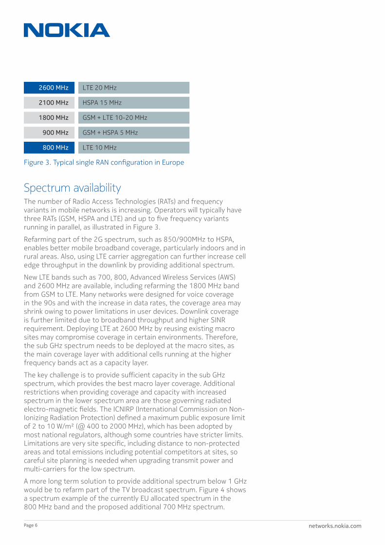
Spectrum availabilityThe number of Radio Access Technologies (RATs) and frequency variants in mobile networks is increasing. Operators will typically have three RATs (GSM, HSPA and LTE) and up to five frequency variants running in parallel, as illustrated in Figure 3.
Refarming part of the 2G spectrum, such as 850/900MHz to HSPA, enables better mobile broadband coverage, particularly indoors and in rural areas. Also, using LTE carrier aggregation can further increase cell edge throughput in the downlink by providing additional spectrum.
New LTE bands such as 700, 800, Advanced Wireless Services (AWS) and 2600 MHz are available, including refarming the 1800 MHz band from GSM to LTE. Many networks were designed for voice coverage in the 90s and with the increase in data rates, the coverage area may shrink owing to power limitations in user devices. Downlink coverage is further limited due to broadband throughput and higher SINR requirement. Deploying LTE at 2600 MHz by reusing existing macro sites may compromise coverage in certain environments. Therefore, the sub GHz spectrum needs to be deployed at the macro sites, as the main coverage layer with additional cells running at the higher frequency bands act as a capacity layer.
The key challenge is to provide sufficient capacity in the sub GHz spectrum, which provides the best macro layer coverage. Additional restrictions when providing coverage and capacity with increased spectrum in the lower spectrum area are those governing radiated electro-magnetic fields. The ICNIRP (International Commission on Non-Ionizing Radiation Protection) defined a maximum public exposure limit of 2 to 10 W/m² (@ 400 to 2000 MHz), which has been adopted by most national regulators, although some countries have stricter limits. Limitations are very site specific, including distance to non-protected areas and total emissions including potential competitors at sites, so careful site planning is needed when upgrading transmit power and multi-carriers for the low spectrum.
A more long term solution to provide additional spectrum below 1 GHz would be to refarm part of the TV broadcast spectrum. Figure 4 shows a spectrum example of the currently EU allocated spectrum in the 800 MHz band and the proposed additional 700 MHz spectrum.
Figure 3. Typical single RAN configuration in Europe
2600 MHz
800 MHz
900 MHz
1800 MHz
2100 MHz
LTE 20 MHz
LTE 10 MHz
GSM + HSPA 5 MHz
GSM + LTE 10-20 MHz
HSPA 15 MHz
networks.nokia.comPage 7
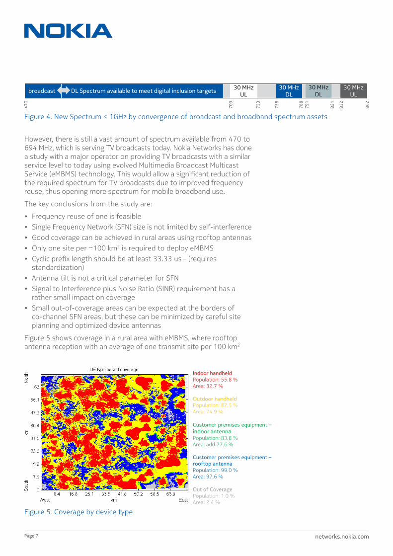
However, there is still a vast amount of spectrum available from 470 to 694 MHz, which is serving TV broadcasts today. Nokia Networks has done a study with a major operator on providing TV broadcasts with a similar service level to today using evolved Multimedia Broadcast Multicast Service (eMBMS) technology. This would allow a significant reduction of the required spectrum for TV broadcasts due to improved frequency reuse, thus opening more spectrum for mobile broadband use.
The key conclusions from the study are:
• Frequency reuse of one is feasible• Single Frequency Network (SFN) size is not limited by self-interference• Good coverage can be achieved in rural areas using rooftop antennas• Only one site per ~100 km2 is required to deploy eMBMS• Cyclic prefix length should be at least 33.33 us – (requires
standardization)• Antenna tilt is not a critical parameter for SFN• Signal to Interference plus Noise Ratio (SINR) requirement has a
rather small impact on coverage• Small out-of-coverage areas can be expected at the borders of
co-channel SFN areas, but these can be minimized by careful site planning and optimized device antennas
Figure 5 shows coverage in a rural area with eMBMS, where rooftop antenna reception with an average of one transmit site per 100 km2
703
733
758
30 MHz DL
788
79
1
821
832
862
30 MHz UL
30 MHz DL
470
DL Spectrum available to meet digital inclusion targets broadcast 30 MHz UL
Figure 4. New Spectrum < 1GHz by convergence of broadcast and broadband spectrum assets
Indoor handheld Population: 55.8 % Area: 32.7 % Outdoor handheld Population: 82.5 % Area: 74.9 % Customer premises equipment – indoor antenna Population: 83.8 % Area: add 77.6 % Customer premises equipment – rooftop antenna Population: 99.0 % Area: 97.6 % Out of Coverage Population: 1.0 % Area: 2.4 %
Figure 5. Coverage by device type
networks.nokia.comPage 8
of rural area is needed to cover 95% of the area and 97% of the population. One LTE 20 MHz carrier can accommodate approximately five HDTV channels by reusing existing LTE deployment. Assuming the delivery of 25 simultaneous HDTV transmissions, 100 MHz spectrum would be needed for the TV service (470-570 MHz), freeing an additional 130 MHz spectrum from 570-700 MHz for mobile broadband services.
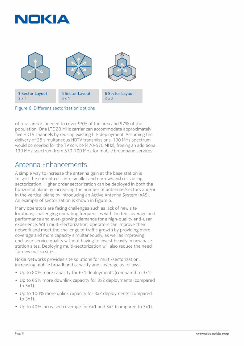
Antenna EnhancementsA simple way to increase the antenna gain at the base station is to split the current cells into smaller and narrowband cells using sectorization. Higher order sectorization can be deployed in both the horizontal plane by increasing the number of antennas/sectors and/or in the vertical plane by introducing an Active Antenna System (AAS). An example of sectorization is shown in Figure 6.
Many operators are facing challenges such as lack of new site locations, challenging operating frequencies with limited coverage and performance and ever-growing demands for a high-quality end-user experience. With multi-sectorization, operators can improve their network and meet the challenge of traffic growth by providing more coverage and more capacity simultaneously, as well as improving end-user service quality without having to invest heavily in new base station sites. Deploying multi-sectorization will also reduce the need for new macro sites.
Nokia Networks provides site solutions for multi-sectorization, increasing mobile broadband capacity and coverage as follows:
• Up to 80% more capacity for 6x1 deployments (compared to 3x1).
• Up to 65% more downlink capacity for 3x2 deployments (compared to 3x1).
• Up to 100% more uplink capacity for 3x2 deployments (compared to 3x1).
• Up to 40% increased coverage for 6x1 and 3x2 (compared to 3x1).
3 Sector Layout 3 x 1
6 Sector Layout 6 x 1
6 Sector Layout 3 x 2
Figure 6. Different sectorization options
networks.nokia.comPage 9
Advanced features such as vertical beam forming, Multiple Input Multiple Output (MIMO) and independent TX and RX electrical tilting for each frequency or radio access technology further improve coverage and capacity.
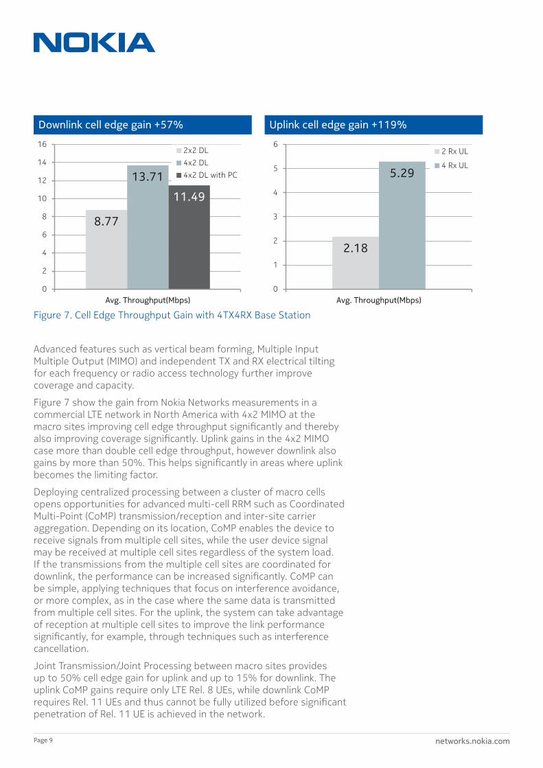
Figure 7 show the gain from Nokia Networks measurements in a commercial LTE network in North America with 4x2 MIMO at the macro sites improving cell edge throughput significantly and thereby also improving coverage significantly. Uplink gains in the 4x2 MIMO case more than double cell edge throughput, however downlink also gains by more than 50%. This helps significantly in areas where uplink becomes the limiting factor.
Deploying centralized processing between a cluster of macro cells opens opportunities for advanced multi-cell RRM such as Coordinated Multi-Point (CoMP) transmission/reception and inter-site carrier aggregation. Depending on its location, CoMP enables the device to receive signals from multiple cell sites, while the user device signal may be received at multiple cell sites regardless of the system load. If the transmissions from the multiple cell sites are coordinated for downlink, the performance can be increased significantly. CoMP can be simple, applying techniques that focus on interference avoidance, or more complex, as in the case where the same data is transmitted from multiple cell sites. For the uplink, the system can take advantage of reception at multiple cell sites to improve the link performance significantly, for example, through techniques such as interference cancellation.
Joint Transmission/Joint Processing between macro sites provides up to 50% cell edge gain for uplink and up to 15% for downlink. The uplink CoMP gains require only LTE Rel. 8 UEs, while downlink CoMP requires Rel. 11 UEs and thus cannot be fully utilized before significant penetration of Rel. 11 UE is achieved in the network.
Downlink cell edge gain +57% Uplink cell edge gain +119%
8.77
13.71
11.49
0
2
4
6
8
10
12
14
16
Avg. Throughput(Mbps)
2x2 DL 4x2 DL 4x2 DL with PC
2.18
5.29
0
1
2
3
4
5
6
Avg. Throughput(Mbps)
2 Rx UL
4 Rx UL
Figure 7. Cell Edge Throughput Gain with 4TX4RX Base Station
networks.nokia.comPage 10
Small cellsSmall cells are an efficient way to provide outdoor coverage, particularly in high capacity areas where the macro cell lacks the ability to provide the necessary cell edge coverage and capacity. The dominance or coverage area of the small cell depends on the transmission (TX) power, the spectrum used and the micro cell selection parameters. The larger the coverage area of a micro cell, the more user equipment it attracts. With high traffic volumes, the micro cells may become congested. In this case, it is better to provide an additional micro-carrier than to reduce the micro TX power. Reducing TX power in outdoor micro cells, combined with increasing data rates, increases the possibility of coverage holes.
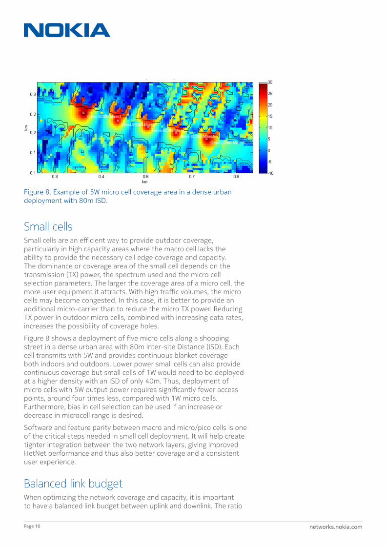
Figure 8 shows a deployment of five micro cells along a shopping street in a dense urban area with 80m Inter-site Distance (ISD). Each cell transmits with 5W and provides continuous blanket coverage both indoors and outdoors. Lower power small cells can also provide continuous coverage but small cells of 1W would need to be deployed at a higher density with an ISD of only 40m. Thus, deployment of micro cells with 5W output power requires significantly fewer access points, around four times less, compared with 1W micro cells. Furthermore, bias in cell selection can be used if an increase or decrease in microcell range is desired.
Software and feature parity between macro and micro/pico cells is one of the critical steps needed in small cell deployment. It will help create tighter integration between the two network layers, giving improved HetNet performance and thus also better coverage and a consistent user experience.
Balanced link budgetWhen optimizing the network coverage and capacity, it is important to have a balanced link budget between uplink and downlink. The ratio
Figure 8. Example of 5W micro cell coverage area in a dense urban deployment with 80m ISD.
networks.nokia.comPage 11
of UL/DL traffic load varies significantly between different devices, laptops and dongles, typically in a1:4 ratio, while smartphones can have up to 1:10 due to streaming being one of their key use cases. The ideal network upgrade depends on which link is currently limiting the performance. UL performance limitations often result from a tight link budget. In this case, additional macro carriers will not improve the performance, micro cell deployment at the cell edges having the largest impact. DL performance on the other hand can be compensated for by additional macro carriers. With the same frequency, the uplink coverage TD-LTE will be lower compared to FDD LTE, since the user device is limited in transmit power. The TD-LTE will be able to transmit a fraction of the time and thus, with a balanced UL:DL ratio, the TD-LTE will have 3dB lower coverage. However, TD-LTE has many other advantages compared to FDD LTE, meaning that resources can be assigned asymmetrically in uplink and downlink and better match the user behavior. Furthermore, the limitations in TD-LTE uplink can be compensated for by the techniques addressed in this whitepaper.
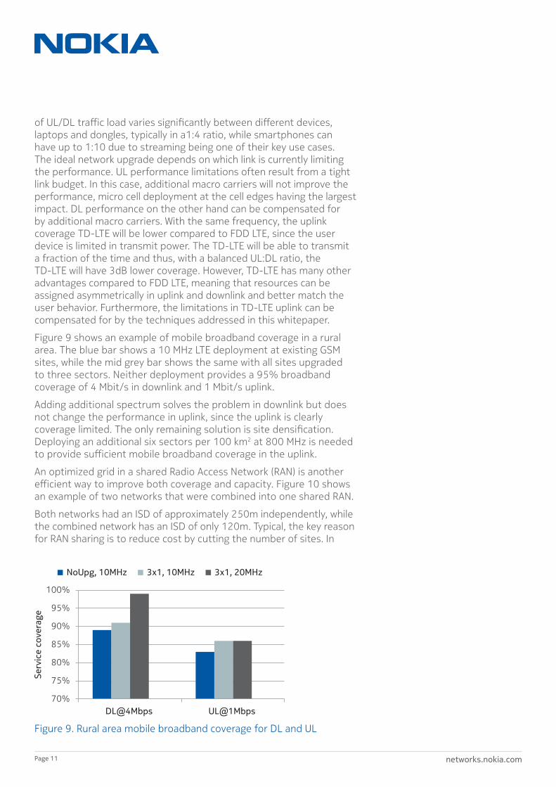
Figure 9 shows an example of mobile broadband coverage in a rural area. The blue bar shows a 10 MHz LTE deployment at existing GSM sites, while the mid grey bar shows the same with all sites upgraded to three sectors. Neither deployment provides a 95% broadband coverage of 4 Mbit/s in downlink and 1 Mbit/s uplink.
Adding additional spectrum solves the problem in downlink but does not change the performance in uplink, since the uplink is clearly coverage limited. The only remaining solution is site densification. Deploying an additional six sectors per 100 km2 at 800 MHz is needed to provide sufficient mobile broadband coverage in the uplink.
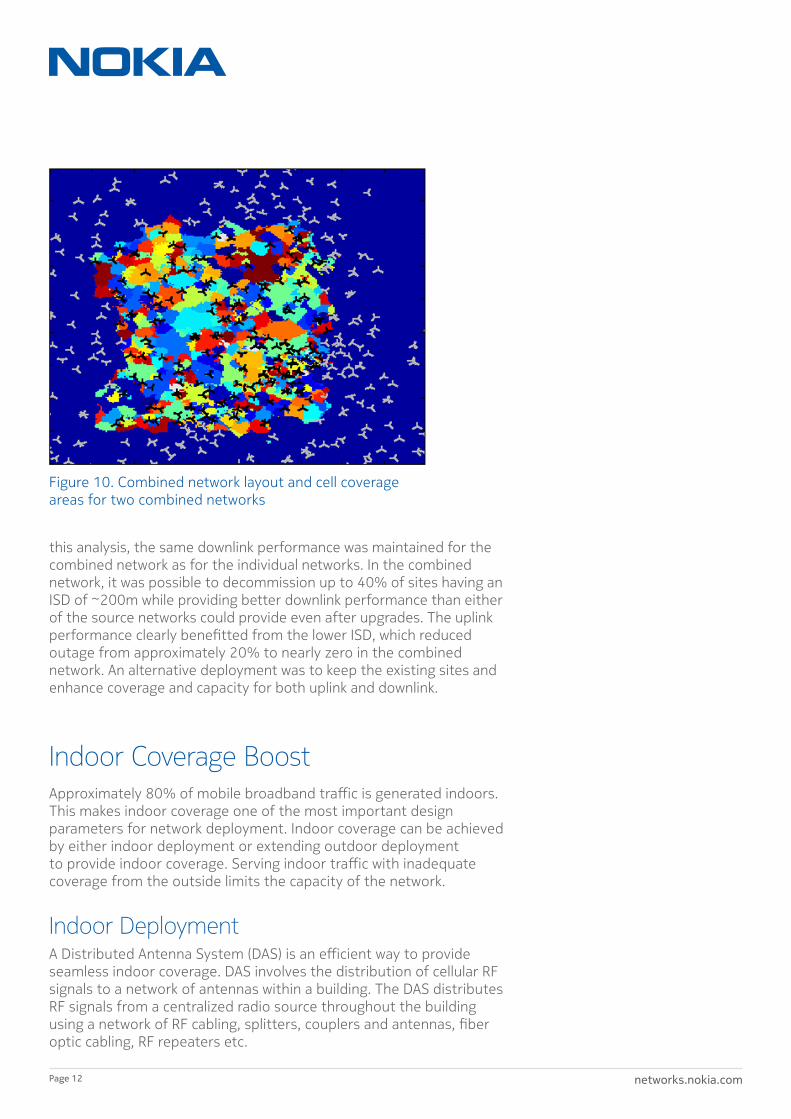
An optimized grid in a shared Radio Access Network (RAN) is another efficient way to improve both coverage and capacity. Figure 10 shows an example of two networks that were combined into one shared RAN.
Both networks had an ISD of approximately 250m independently, while the combined network has an ISD of only 120m. Typical, the key reason for RAN sharing is to reduce cost by cutting the number of sites. In
70%
75%
80%
85%
90%
95%
100%
DL@4Mbps UL@1Mbps
Serv
ice
cove
rage
NoUpg, 10MHz 3x1, 10MHz 3x1, 20MHz
Figure 9. Rural area mobile broadband coverage for DL and UL
networks.nokia.comPage 12
this analysis, the same downlink performance was maintained for the combined network as for the individual networks. In the combined network, it was possible to decommission up to 40% of sites having an ISD of ~200m while providing better downlink performance than either of the source networks could provide even after upgrades. The uplink performance clearly benefitted from the lower ISD, which reduced outage from approximately 20% to nearly zero in the combined network. An alternative deployment was to keep the existing sites and enhance coverage and capacity for both uplink and downlink.
Indoor Coverage BoostApproximately 80% of mobile broadband traffic is generated indoors. This makes indoor coverage one of the most important design parameters for network deployment. Indoor coverage can be achieved by either indoor deployment or extending outdoor deployment to provide indoor coverage. Serving indoor traffic with inadequate coverage from the outside limits the capacity of the network.
Indoor DeploymentA Distributed Antenna System (DAS) is an efficient way to provide seamless indoor coverage. DAS involves the distribution of cellular RF signals to a network of antennas within a building. The DAS distributes RF signals from a centralized radio source throughout the building using a network of RF cabling, splitters, couplers and antennas, fiber optic cabling, RF repeaters etc.
Figure 10. Combined network layout and cell coverage areas for two combined networks

networks.nokia.comPage 13
The aim is to create an indoor layer that is integrated seamlessly with the macro layer and which handles voice & data traffic internal to the building, thereby offering better quality and user experience.
Another way to provide indoor coverage is by deploying indoor small cells. In dense urban deployments, indoor 4G/LTE small cell and WLAN/ 802.11n/ac solutions (or combined multi-RAT small cells) can provide excellent coverage and capacity, as exemplified in Figure 11. The ratio of users getting more than 10 Mbit/s is increased from 80% to 90% by deploying an indoor cell for every ~500m2.
In enterprise deployment, where the locations and transmit power levels of the indoor small cells (Wi-Fi or pico) can be optimized, the number of indoor small cells required can be reduced significantly, providing a reduction in costs of up to 45% compared to the costs of un-planned residential -like deployment solutions.
In public deployment environments, such as large multi-floor shopping malls, a deployment density of one indoor pico cell per 1000 m2 of floor area is sufficient to provide the minimum user data rate of 10 Mbit/s in a 2020 traffic growth scenario.
Figure 12 shows examples of capacity of different indoor solutions in a 60 floor high rise building, with each scenario providing 95% coverage. The first case uses DAS for indoor coverage and the second uses the DAS infrastructure with a small cell on every floor, doubling the capacity. Deploying further small cells improves capacity significantly. The final case shows a combination of DAS in the common area and small cells in the dedicated office areas. The indoor deployment with distributed small cells provides significantly more capacity, with the same coverage as DAS.
0%
10%
20%
30%
40%
50%
60%
70%
80%
90%
100%
Without Indoor
Use
rs w
ith th
roug
hput
> 1
0 M
bit/
s
small-cells With Indoor small-cells
Indoor small-cell Pico Macro
Figure 11. Example of outdoor and indoor small cell (4G/LTE and Wi-Fi 802.11n/ac) coverage probability performance under a typical dense urban deployment scenario as expected in 2020.

networks.nokia.comPage 14
Outdoor deployment for indoor coverage Indoor coverage can be provided in similar ways to all the mechanisms explained in the Outdoor Coverage Boost section, provided that the additional wall penetration is covered by the link budget. However, dedicated outdoor deployment for indoor coverage is also a viable solution. Figure 8 shows an example of outdoor micro cell deployment along a street. Such a solution will also provide good indoor coverage for the buildings along the street for the lower floors. Uplink coverage is particularly improved by deploying outdoor small cells, as the building penetration loss is typically a limiting factor for the uplink.
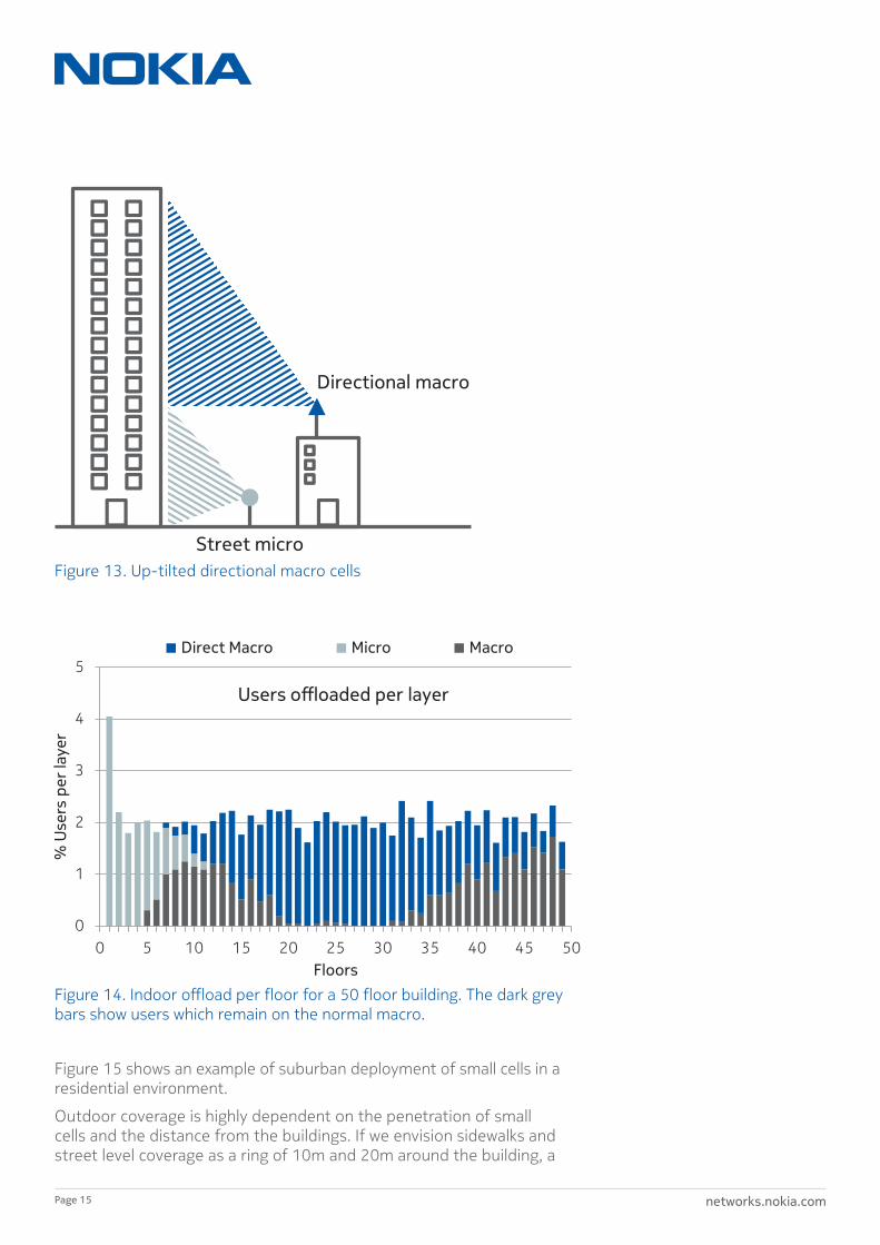
Deploying outdoor small cells for a dense urban high rise environment does not solve the challenge of indoor coverage above the first 5-10 floors. Additional micro cells can be deployed at the rooftop of the tallest building but again they only provide coverage for the upper 5-10 floors. Therefore, for dense urban high rise environments, either an in building solution or a macro based solution is needed, with directional antennas pointing upwards to provide coverage and capacity for dense high rise streets.
Figure 13 shows an example of a high rise building covered by a street level micro cell for the low floors with the upper floors covered by a nearby macro site with directional antenna tilted upwards. The macro antenna beam can be narrow, with additional antenna gain to cover specific buildings.
Figure 14 shows the offload potential of the example above, showing that the users on the lower floors are primarily using the street level micro cell. The directional macro cell offloads the middle part and the upper part respectively, providing both coverage and capacity for dense urban high rises without the need for indoor deployment.
Indoor-to-outdoorA completely different approach to providing coverage would be to deploy indoor small cells for both indoor and outdoor coverage.
Figure 12. Capacity of different indoor solutions in a 60 floor high rise building.
Scenario
# of eNB/small cells per floor
# of Antennas
Capacity per Floor
20W eNB connected to DAS 1 per 2 floors 21 56 Mbps
5W small cell connected to DAS 1 21 112 Mbps
5W small cell with built-in antenna 8 8 543 Mbps
0.25W small cell with built-in antenna 18 18 1,335 Mbps
5W small cell connected to DAS in COMMON- AREAS-ONLY and 0.25W in other areas.
1 five-W and 5 quarter-W
19 (14 DAS + 5 Built In)
489 Mbps
networks.nokia.comPage 15
0
1
2
3
4
5
0 5 10 15 20 25 30 35 40 45 50
% U
sers
per
laye
r
Floors
Users offloaded per layer
Direct Macro Micro Macro
Figure 14. Indoor offload per floor for a 50 floor building. The dark grey bars show users which remain on the normal macro.
Figure 15 shows an example of suburban deployment of small cells in a residential environment.
Outdoor coverage is highly dependent on the penetration of small cells and the distance from the buildings. If we envision sidewalks and street level coverage as a ring of 10m and 20m around the building, a
Directional macro
Street micro
Figure 13. Up-tilted directional macro cells

networks.nokia.comPage 16
50% outdoor coverage for the 20m ring can be provided by 10% of all households installing a small cell. Assuming that there are four operators with an equal subscriber base in the area, then a 10% total penetration would require 40% penetration from a single operator to provide the 50% coverage if no RAN sharing is assumed. Therefore, the necessary outdoor coverage from indoor small cells may be difficult to reach. The increased penetration loss due to better insulation and metal coating will further limit the outdoor coverage from small cells. This topic is further described in the next section.
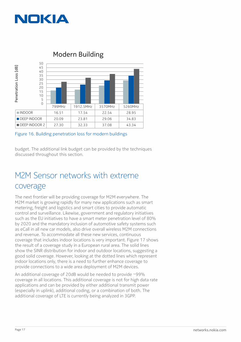
Deep indoor coverageIndoor coverage takes on another challenge when talking about deep indoor coverage. Deep indoor coverage entails providing coverage inside a mall, tunnels and the basement of a residential building or in the centre of large indoor complexes. Furthermore, many new buildings around the globe will have higher penetration loss through the use of metal coated windows to minimize reflections of the sun and walls, with more insulation to reduce heating and cooling. Therefore, the traditional building penetration loss of 10 dB will no longer be sufficient for providing deep indoor coverage. Nokia Networks has carried out a measurement campaign in different environments, evaluating outdoor-to-indoor penetration loss. The measurements were carried out in three different indoor locations:
• INDOOR: 1st row of offices.
• DEEP INDOOR: central corridor.
• DEEP INDOOR 2: 2nd row of offices.
Furthermore, increasing the carrier frequency to 3.5 or 5 GHz for capacity increases the building penetration loss. Figure 16 shows the results of measurements of building penetration loss, with a focus on modern buildings with a metal coating on the windows and thick insulation in the walls. The measurements show that building penetration of 16-29 dB can be expected with an increase of 10-15 dB for deep indoor coverage. Therefore, to provide a good user experience, an outdoor to indoor penetration of 25-35 dB should be included in the link
Building
20m Ring
10m Ring
Small cell penetration [%]
Out
door
are
a co
vere
d by
sm
all c
ells
[%]
0
10
20
30
40
50
60
70
0 5 10 15 20
All
10m ring
20m ring
Figure 15. Outdoor coverage by indoor small cells deployment
networks.nokia.comPage 17
budget. The additional link budget can be provided by the techniques discussed throughout this section.
M2M Sensor networks with extreme coverageThe next frontier will be providing coverage for M2M everywhere. The M2M market is growing rapidly for many new applications such as smart metering, freight and logistics and smart cities to provide automatic control and surveillance. Likewise, government and regulatory initiatives such as the EU initiatives to have a smart meter penetration level of 80% by 2020 and the mandatory inclusion of automotive safety systems such as eCall in all new car models, also drive overall wireless M2M connections and revenue. To accommodate all these new services, continuous coverage that includes indoor locations is very important. Figure 17 shows the result of a coverage study in a European rural area. The solid lines show the SINR distribution for indoor and outdoor locations, suggesting a good solid coverage. However, looking at the dotted lines which represent indoor locations only, there is a need to further enhance coverage to provide connections to a wide area deployment of M2M devices.
An additional coverage of 20dB would be needed to provide ~99% coverage in all locations. This additional coverage is not for high data rate applications and can be provided by either additional transmit power (especially in uplink), additional coding, or a combination of both. The additional coverage of LTE is currently being analyzed in 3GPP.
799MHz 1912.5MHz 3570MHz 5260MHz
INDOOR 16.51 17.54 22.54 28.95
DEEP INDOOR 20.09 23.81 29.06 34.83
DEEP INDOOR 2 27.30 32.33 37.08 43.34
0 5
10 15 20 25 30 35 40 45 50
Pene
trat
ion
Loss
[dB]
Modern Building
Figure 16. Building penetration loss for modern buildings

networks.nokia.comPage 18
RecommendationsThis whitepaper outlines the main challenges and solutions to providing better coverage in today’s mobile broadband networks while at the same time providing additional capacity. The key coverage enhancement techniques are summarized in Figure 18.
0
0.1
0.2
0.3
0.4
0.5
0.6
0.7
0.8
0.9
1
-30 -20 -10 0 10 20 30 SINR [dB]
0 dB, whole area
10 dB, whole area
20 dB, whole area
25 dB, whole area
0 dB, indoor area
10 dB, indoor area
20 dB, indoor area
25 dB, indoor area
Figure 17. SINR CDF for indoor coverage in rural area
Indoor
Massive M2M
Outdoor
Refarming Coverage by lower path loss (e.g. LTE700/800)
Cell splitting Provides coverage by higher antenna gain
Small cells Provides coverage in cell edge and hot spot areas
Network sharing Provides coverage by combined network
Indoor small cells
Provides coverage and capacity w/ feature parity
Outdoor to indoor
Provides coverage but limited by penetration loss
Directional antennas
Provides coverage by dedicated antennas
M2M 20 dB coverage required Standardization ongoing
Indoor DAS Provides indoor coverage by distributed antennas
Figure 18. Key recommendations for coverage enhancements
networks.nokia.comPage 19
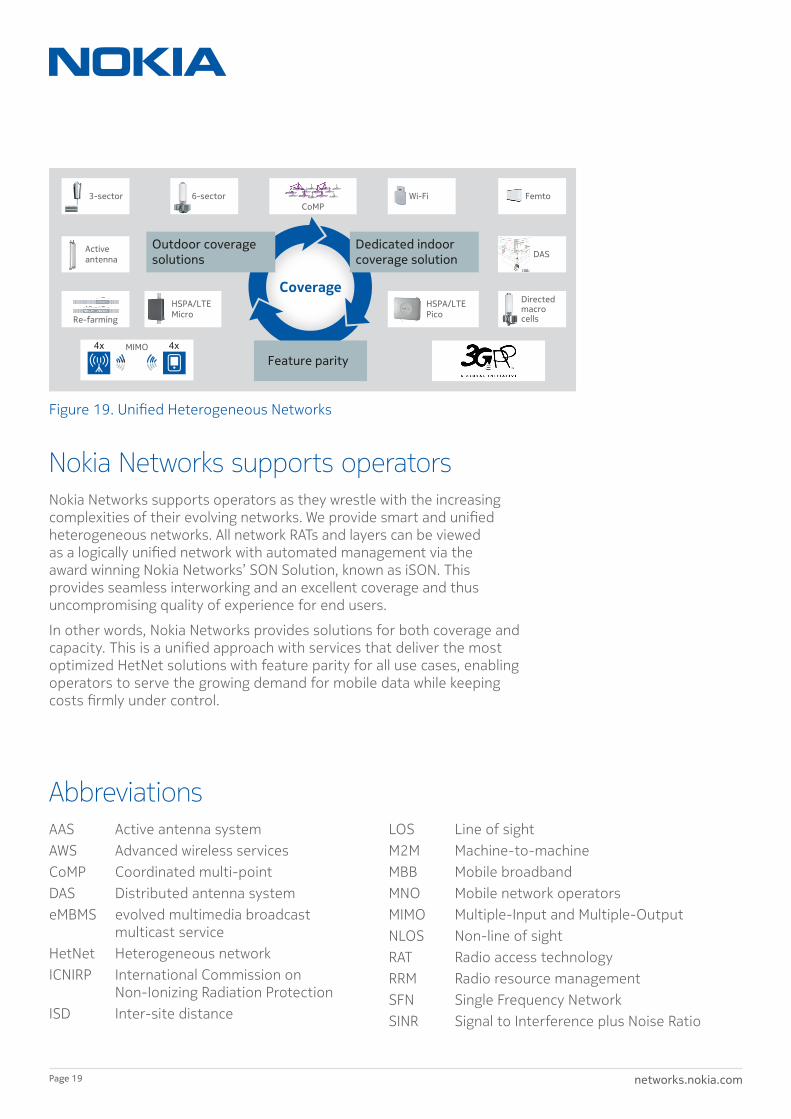
Nokia Networks supports operatorsNokia Networks supports operators as they wrestle with the increasing complexities of their evolving networks. We provide smart and unified heterogeneous networks. All network RATs and layers can be viewed as a logically unified network with automated management via the award winning Nokia Networks’ SON Solution, known as iSON. This provides seamless interworking and an excellent coverage and thus uncompromising quality of experience for end users.
In other words, Nokia Networks provides solutions for both coverage and capacity. This is a unified approach with services that deliver the most optimized HetNet solutions with feature parity for all use cases, enabling operators to serve the growing demand for mobile data while keeping costs firmly under control.
AbbreviationsAAS Active antenna systemAWS Advanced wireless servicesCoMP Coordinated multi-pointDAS Distributed antenna systemeMBMS evolved multimedia broadcast
multicast serviceHetNet Heterogeneous networkICNIRP International Commission on
Non-Ionizing Radiation ProtectionISD Inter-site distance
LOS Line of sightM2M Machine-to-machineMBB Mobile broadbandMNO Mobile network operatorsMIMO Multiple-Input and Multiple-OutputNLOS Non-line of sightRAT Radio access technologyRRM Radio resource managementSFN Single Frequency NetworkSINR Signal to Interference plus Noise Ratio
Coverage
Outdoor coverage solutions
Dedicated indoor coverage solution
Feature parity
3-sector 6-sector CoMP
Femto Wi-Fi
DAS
Re-farming
Directed macro cells
HSPA/LTE Pico
HSPA/LTE Micro
MIMO 4x 4x
Activeantenna
Figure 19. Unified Heterogeneous Networks
networks.nokia.com
Nokia is a registered trademark of Nokia Corporation. Other product and company names mentioned herein may be trademarks or trade names of their respective owners.
Nokia Nokia Solutions and Networks Oy P.O. Box 1 FI-02022 Finland
Visiting address: Karaportti 3, ESPOO, Finland Switchboard +358 71 400 4000
Product code C401-00978-WP-201404-1-EN
© Nokia Solutions and Networks 2014