Noise-free holographic storage in iron-doped lithium niobate crystals
3
October 1, 1994 / Vol. 19, No. 19 / OPTICS LETTERS 1583 Noise-free holographic storage in iron-doped lithium niobate crystals Peter E. Andersen and Abdellatif Marrakchi Physics Department, Technical University of Denmark, 2800 Lyngby, Denmark Received May 2, 1994 We show that fanning noise in lithium niobate crystals can have a deleterious effect on holographic storage in configurations in which the c axis and the grating wave vector coincide,for both ordinary and extraordinary light polarizations. We then demonstrate that this noise is drastically reduced when the c axis is perpendicular to the grating wave vector. Images have been fixed and read out for many hours at high intensity levels, demonstrating long-term storage and good-quality image recall. Three-dimensional high-capacity holographic storage with parallel access has a variety of applications ranging from the archiving of gray-level or binary images to the fabrication of multiplexed arrays of holographic optical elements. Compared with pho- tolithographic techniques and etching, holographic recording of such devices in photorefractive mate- rials followed by subsequent fixing has the advan- tages of yielding high efficiency and being a much simpler in situ fabrication technique with real-time control. Recording and readout of information in photorefractive crystals in the form of holographic phase gratings is well understood' and was success- fully applied to the optical storage of 10,000 high- resolution holograms. 2 Photorefractive materials have also proved their suitability for other appli- cations such as dynamic optical interconnects 3 and optical clock distribution.' The issue of hologram fixing was also investigated for a variety of photore- fractive materials. 56 Most crystals that have been used to date, however, exhibit light scattering as a result of beam fanning, 7 which can be a source of noise in photorefractive holographic devices. In this Letter we report that, when the c axis of the crystal is perpendicular to the plane of incidence, the fanning noise is not superimposed onto the diffracted image. We have applied this technique to the recording, thermal fixing, and recall of images with good optical quality, even after many hours of readout with an intense beam. Beam fanning arises from light scattered from impurity centers in the photorefractive sample. In the case of doped crystals this fanning can be sub- stantial compared with that in nominally pure sam- ples because the dopants act as additional scattering centers and can therefore be a source of additional noise in holographic recording. Doping the crys- tal, however, enhances the photorefractive sensitiv- ity drastically, e.g., in iron-doped lithium niobate crystals. 8 Hence a trade-off exists between the de- sired increase in photorefractive sensitivity and the unwanted additional contribution to fanning noise. The fixing process is also affected by the level of iron doping. Thermal fixing was demonstrated most successfully in undoped and lightly doped lithium niobate crystals, 8 imposing a second trade-off: a high doping level yielding high sensitivity reduces the thermal fixing efficiency. Note that heavily doped crystals exhibit poor or no thermal fixing. 8 The information is stored in electro-optic crystals by means of the photorefractive effect.' If no pre- caution is taken during the readout process, this information is erased as a result of the uniform redistribution of charges. One can achieve nonde- structive readout either by changing the readout wavelength 9 or by thermally fixing the hologram.' 0 In our experiments we have chosen to study doped lithium niobate and the latter approach since it per- mits nondestructive readout with the original ref- erence beam, thus avoiding the problem of phase matching when different wavelengths are used for recording and readout. However, by reading out with the original reference beam one may record new unwanted gratings that are due to scattering and to the fact that the material is highly sensi- tive at this wavelength. This causes beam fanning 7 to build up. The fanning is induced along the c axis of the crystal and polarized as the incident and diffracted light in the case of isotropic diffrac- tion only." Hence, when the c axis lies in the plane of incidence, the fanning and the diffracted beam cannot be separated spatially or by the use of a po- larizer. The fanning can be powerful compared with the diffracted signal level and therefore generates unwanted noise. Consider the setup shown in Fig. 1. Two beams are incident upon the iron-doped lithium niobate crystal: the reference beam with an intensity of 60 mW/cm 2 and the image-bearing beam with a power of 10 mW. The crystal is a 1 cm X 1 cm X 1 cm sample with an iron doping of 0.010 mol. %. The intersection angle between the reference and the image beam paths is 250. These beams are derived from a linearly polarized Ar' laser with a wavelength of 515 nm. The recording time is short compared with the response time for the buildup of fanning. The image is either a U.S. Air Force reso- lution target or a Spoke target. After recording, we removed the crystal for the thermal fixing procedure's and then remounted it in the setup for the reveal- 0146-9592/94/191583-03$6.00/0 © 1994 Optical Society of America
-
Upload
abdellatif -
Category
Documents
-
view
216 -
download
3
Transcript of Noise-free holographic storage in iron-doped lithium niobate crystals

October 1, 1994 / Vol. 19, No. 19 / OPTICS LETTERS 1583
Noise-free holographic storage in iron-dopedlithium niobate crystals
Peter E. Andersen and Abdellatif Marrakchi
Physics Department, Technical University of Denmark, 2800 Lyngby, Denmark
Received May 2, 1994
We show that fanning noise in lithium niobate crystals can have a deleterious effect on holographic storage inconfigurations in which the c axis and the grating wave vector coincide, for both ordinary and extraordinary lightpolarizations. We then demonstrate that this noise is drastically reduced when the c axis is perpendicular to thegrating wave vector. Images have been fixed and read out for many hours at high intensity levels, demonstratinglong-term storage and good-quality image recall.
Three-dimensional high-capacity holographic storagewith parallel access has a variety of applicationsranging from the archiving of gray-level or binaryimages to the fabrication of multiplexed arrays ofholographic optical elements. Compared with pho-tolithographic techniques and etching, holographicrecording of such devices in photorefractive mate-rials followed by subsequent fixing has the advan-tages of yielding high efficiency and being a muchsimpler in situ fabrication technique with real-timecontrol. Recording and readout of information inphotorefractive crystals in the form of holographicphase gratings is well understood' and was success-fully applied to the optical storage of 10,000 high-resolution holograms.2 Photorefractive materialshave also proved their suitability for other appli-cations such as dynamic optical interconnects3 andoptical clock distribution.' The issue of hologramfixing was also investigated for a variety of photore-fractive materials.5 6 Most crystals that have beenused to date, however, exhibit light scattering as aresult of beam fanning,7 which can be a source ofnoise in photorefractive holographic devices. In thisLetter we report that, when the c axis of the crystal isperpendicular to the plane of incidence, the fanningnoise is not superimposed onto the diffracted image.We have applied this technique to the recording,thermal fixing, and recall of images with good opticalquality, even after many hours of readout with anintense beam.
Beam fanning arises from light scattered fromimpurity centers in the photorefractive sample. Inthe case of doped crystals this fanning can be sub-stantial compared with that in nominally pure sam-ples because the dopants act as additional scatteringcenters and can therefore be a source of additionalnoise in holographic recording. Doping the crys-tal, however, enhances the photorefractive sensitiv-ity drastically, e.g., in iron-doped lithium niobatecrystals.8 Hence a trade-off exists between the de-sired increase in photorefractive sensitivity and theunwanted additional contribution to fanning noise.The fixing process is also affected by the level ofiron doping. Thermal fixing was demonstrated mostsuccessfully in undoped and lightly doped lithium
niobate crystals,8 imposing a second trade-off: ahigh doping level yielding high sensitivity reduces thethermal fixing efficiency. Note that heavily dopedcrystals exhibit poor or no thermal fixing.8
The information is stored in electro-optic crystalsby means of the photorefractive effect.' If no pre-caution is taken during the readout process, thisinformation is erased as a result of the uniformredistribution of charges. One can achieve nonde-structive readout either by changing the readoutwavelength9 or by thermally fixing the hologram.'0In our experiments we have chosen to study dopedlithium niobate and the latter approach since it per-mits nondestructive readout with the original ref-erence beam, thus avoiding the problem of phasematching when different wavelengths are used forrecording and readout. However, by reading outwith the original reference beam one may recordnew unwanted gratings that are due to scatteringand to the fact that the material is highly sensi-tive at this wavelength. This causes beam fanning7
to build up. The fanning is induced along thec axis of the crystal and polarized as the incidentand diffracted light in the case of isotropic diffrac-tion only." Hence, when the c axis lies in the planeof incidence, the fanning and the diffracted beamcannot be separated spatially or by the use of a po-larizer. The fanning can be powerful compared withthe diffracted signal level and therefore generatesunwanted noise.
Consider the setup shown in Fig. 1. Two beamsare incident upon the iron-doped lithium niobatecrystal: the reference beam with an intensity of60 mW/cm2 and the image-bearing beam with apower of 10 mW. The crystal is a 1 cm X 1 cm X1 cm sample with an iron doping of 0.010 mol. %.The intersection angle between the reference andthe image beam paths is 250. These beams arederived from a linearly polarized Ar' laser with awavelength of 515 nm. The recording time is shortcompared with the response time for the buildup offanning. The image is either a U.S. Air Force reso-lution target or a Spoke target. After recording, weremoved the crystal for the thermal fixing procedure'sand then remounted it in the setup for the reveal-
0146-9592/94/191583-03$6.00/0 © 1994 Optical Society of America

1584 OPTICS LETTERS / Vol. 19, No. 19 / October 1, 1994
Yt Image plane
UNbO;:Fe
UNbO,:Fe > cads
rerence beam
Fig. 1. Schematic of the experimental setup. The insetshows the orientation of the sample in the conventionalconfiguration (the c axis and the grating wave vectorcoincide).
ing procedure. Following the revealing step of thehologram, the quality of the diffracted image is mon-itored during continuous long-term readout with theoriginal reference beam to simulate a situation of alarge number of readout cycles of the fixed hologram.The diffracted image is periodically grabbed with aCCD camera connected to a personal computer witha frame-grabber board. The fixing conversion factoris defined as the ratio of the diffraction efficiency af-ter fixing to the efficiency before fixing. In principle,the conversion could be as large as 100%; however, toour knowledge the highest reported value is -50%.1oIn our experiments the revealing step is carried outwith a single off-Bragg 25-mW/cm2 plane-wave illu-mination for 2 h.
In the first experiment the polarization of the writ-ing beams is extraordinary, and the c axis is in theplane of incidence. The grating wave vector is di-rected along the c axis. This orientation is the mostcommonly used configuration because it provides thelargest effective electro-optic coefficient. The modu-lation of the refractive index along the z direction is
n = n.e - 1/2[ne3rM3 Esc(z)], (1)
where ne is the index of refraction for extraordinarilypolarized light, r33 the effective electro-optic coeffi-cient, and Esc(z) is the induced space-charge field.The space-charge field consists of contributions fromboth diffusion and photovoltaic currents in iron-dopedlithium niobate in this configuration.2 The record-ing time is 1 min. After recording, we removed thecrystal from the setup for the fixing process. Afterthe fixing process we revealed the hologram by shin-ing an off-Bragg plane wave onto the crystal for 2 h.We found that an increase of the revealing time didnot increase the efficiency of the fixed hologram, andthus a steady state was reached. A conversion fac-tor of 10% with an image was consistently measuredin this experiment. The image shown in Fig. 2(a) isthe diffracted image immediately after the revealingprocess. From this figure it can be seen that thefixed hologram has a reasonable resolution and that
the noise level is low. We find from other experi-ments that the fixing process itself does not changethe resolution of the stored hologram. We reach thisconclusion by comparing the diffracted image beforefixing and immediately after the revealing process.Thus, the thermal fixing process can be used for long-term storage. This conclusion is valid for all exper-iments reported here. However, as a result of beamfanning during the readout process, noise starts toaccumulate on top of the diffracted image, as illus-trated in Fig. 2(b), which was captured 15 min later.
Note that the grating is still fixed in the crystal.We checked this by shining a powerful off-Braggplane wave that partly erases the original fanningand observing that the diffracted image appearsagain. Hence the image degradation reported hereis due not to the decay of the fixed gratings but tothe buildup of optical noise caused by beam fanning.
For the second experiment the polarization of theincident beams is changed to ordinary. The directionof the grating wave vector is unchanged. The indexmodulation is now written as
n = n, - 1/2[n03 risEsc(z)], (2)
where no is the index of refraction for ordinarilypolarized light and r13 is the effective electro-opticcoefficient. Note that r,3 < r33 yields a lower in-dex modulation. The recording time is chosen to be4 min for the same total power level as in the firstexperiment to compensate for the lower sensitivityfor this polarization. The hologram is revealed, anda conversion factor of 10% is consistently measured.Figure 3(a) shows the diffracted image immediatelyafter revealing. The image in Fig. 3(b) is captured80 min later and shows that fanning again introducesnoise in the diffracted image.
The experiments described above show that noisethat is due to fanning is a problem when the c axis ofthe crystal lies within the plane of incidence. Thisis caused by the fact that fanning and diffractionoccur along the direction of the c axis. Our approachto reduce the fanning noise is then to record andfix the hologram in a configuration with the c axisperpendicular to the plane of incidence. Since thefanning during the readout process will be inducedin a plane perpendicular to the plane of incidence,the fanning and the diffracted image can easily bespatially separated, thus removing the fanning noise.
(a) (b)Fig. 2. (a) Diffracted image immediately after the re-vealing process with the conventional configuration andextraordinarily polarized light. (b) Diffracted image af-ter 15 min of continuous readout.
October 1, 1994 / Vol. 19, No. 19 / OPTICS LETTERS 1585
approximately 1 h of the readout process. Neverthe-less, it did not disturb the continuous readout process.Thus this experiment proves the concept that we canremove fanning from the diffracted image by havingthe c axis perpendicular to the plane of incidence.
In the fourth experiment the polarization is rotatedto become vertical, i.e., along the c axis. In this casethe electro-optic effect becomes of second order:
(a) (b)Fig. 3. (a) Diffracted image immediately after therevealing process with the conventional configurationand ordinarily polarized light. (b) Diffracted image after80 min of continuous readout.
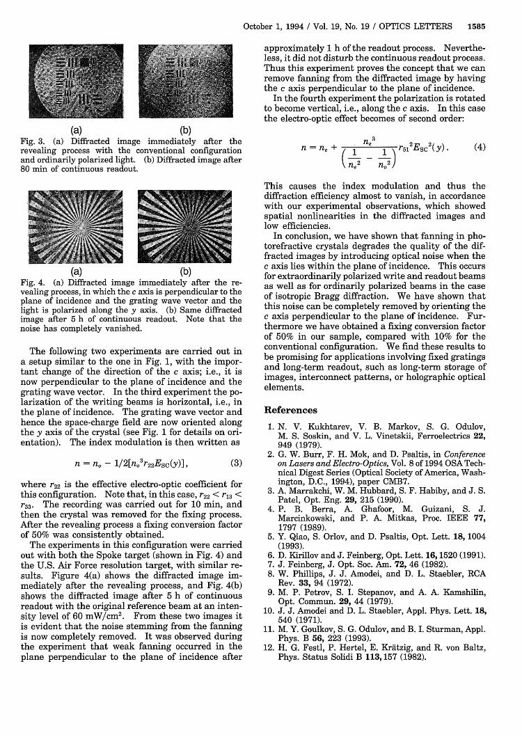
(a) (b)Fig. 4. (a) Diffracted image immediately after the re-vealing process, in which the c axis is perpendicular to theplane of incidence and the grating wave vector and thelight is polarized along the y axis. (b) Same diffractedimage after 5 h of continuous readout. Note that thenoise has completely vanished.
The following two experiments are carried out ina setup similar to the one in Fig. 1, with the impor-tant change of the direction of the c axis; i.e., it isnow perpendicular to the plane of incidence and thegrating wave vector. In the third experiment the po-larization of the writing beams is horizontal, i.e., inthe plane of incidence. The grating wave vector andhence the space-charge field are now oriented alongthe y axis of the crystal (see Fig. 1 for details on ori-entation). The index modulation is then written as
n = n0 - 1/2[n03r 2 2Esc(y)] , (3)
where r22 is the effective electro-optic coefficient forthis configuration. Note that, in this case, r22 < r13 <r33. The recording was carried out for 10 min, andthen the crystal was removed for the fixing process.After the revealing process a fixing conversion factorof 50% was consistently obtained.
The experiments in this configuration were carriedout with both the Spoke target (shown in Fig. 4) andthe U.S. Air Force resolution target, with similar re-sults. Figure 4(a) shows the diffracted image im-mediately after the revealing process, and Fig. 4(b)shows the diffracted image after 5 h of continuousreadout with the original reference beam at an inten-sity level of 60 mW/cm2. From these two images itis evident that the noise stemming from the fanningis now completely removed. It was observed duringthe experiment that weak fanning occurred in theplane perpendicular to the plane of incidence after
n=lne + -( 1 2- 12 r5l2ESc2(y).
n 2 n 2
This causes the index modulation and thus thediffraction efficiency almost to vanish, in accordancewith our experimental observations, which showedspatial nonlinearities in the diffracted images andlow efficiencies.
In conclusion, we have shown that fanning in pho-torefractive crystals degrades the quality of the dif-fracted images by introducing optical noise when thec axis lies within the plane of incidence. This occursfor extraordinarily polarized write and readout beamsas well as for ordinarily polarized beams in the caseof isotropic Bragg diffraction. We have shown thatthis noise can be completely removed by orienting thec axis perpendicular to the plane of incidence. Fur-thermore we have obtained a fixing conversion factorof 50% in our sample, compared with 10% for theconventional configuration. We find these results tobe promising for applications involving fixed gratingsand long-term readout, such as long-term storage ofimages, interconnect patterns, or holographic opticalelements.
References
1. N. V. Kukhtarev, V. B. Markov, S. G. Odulov,M. S. Soskin, and V. L. Vinetskii, Ferroelectrics 22,949 (1979).
2. G. W. Burr, F. H. Mok, and D. Psaltis, in Conferenceon Lasers and Electro-Optics, Vol. 8 of 1994 OSA Tech-nical Digest Series (Optical Society of America, Wash-ington, D.C., 1994), paper CMB7.
3. A. Marrakchi, W. M. Hubbard, S. F. Habiby, and J. S.Patel, Opt. Eng. 29, 215 (1990).
4. P. B. Berra, A. Ghafoor, M. Guizani, S. J.Marcinkowski, and P. A. Mitkas, Proc. IEEE 77,1797 (1989).
5. Y. Qiao, S. Orlov, and D. Psaltis, Opt. Lett. 18, 1004(1993).
6. D. Kirillov and J. Feinberg, Opt. Lett. 16,1520 (1991).7. J. Feinberg, J. Opt. Soc. Am. 72, 46 (1982).8. W. Phillips, J. J. Amodei, and D. L. Staebler, RCA
Rev. 33, 94 (1972).9. M. P. Petrov, S. I. Stepanov, and A. A. Kamshilin,
Opt. Commun. 29, 44 (1979).10. J. J. Amodei and D. L. Staebler, Appl. Phys. Lett. 18,
540 (1971).11. M. Y. Goulkov, S. G. Odulov, and B. I. Sturman, Appl.
Phys. B 56, 223 (1993).12. H. G. Festl, P. Hertel, E. Kratzig, and R. von Baltz,
Phys. Status Solidi B 113,157 (1982).
(4)


![Localized Holographic Recording in doubly doped Lithium ...LiNbO3 [1]. The technique is based on the recording oflocalized holograms in thin layers across the volume ofthe crystal.](https://static.fdocuments.us/doc/165x107/5e9706003ad76c38971939f3/localized-holographic-recording-in-doubly-doped-lithium-linbo3-1-the-technique.jpg)