No. - Defense Technical Information · PDF fileLIMITATION OF ABSTRACT ... - BRAKE BOOSTER ......
199
No. 13546 IMPROVED RECOVERY VEHICLE (IRV) M88AIE1 HYDRAULIC SYSTEM ANALYSIS September 1991 Ronald J. Chapp Steven K. Knott U.S. Army Tank-Automotive Command ATTN: AMSTA-ZDS SBy Warren, MI 48397-5000 APPROVED FOR PUBLIC RELEASE: DISTRIBUTION IS UNLIMITED * U.S. ARMY TANK-AUTOMOTIVE COMMAND RESEARCH, DEVELOPMENT & ENGINEERING CENTER Warren, Michigan 48397-5000
Transcript of No. - Defense Technical Information · PDF fileLIMITATION OF ABSTRACT ... - BRAKE BOOSTER ......
No. 13546
IMPROVED RECOVERY VEHICLE (IRV)
M88AIE1 HYDRAULIC SYSTEM ANALYSIS
September 1991
Ronald J. ChappSteven K. KnottU.S. Army Tank-Automotive CommandATTN: AMSTA-ZDS
SBy Warren, MI 48397-5000
APPROVED FOR PUBLIC RELEASE:DISTRIBUTION IS UNLIMITED
* U.S. ARMY TANK-AUTOMOTIVE COMMANDRESEARCH, DEVELOPMENT & ENGINEERING CENTERWarren, Michigan 48397-5000

NOTICES
This report is not to be construed as an official Department ofthe Army position.
Mention of any trade names or imnufacturers in this report shallnot be construed as an official endorsement or approval of suchproducts or companies by the U.S. Government.
Destroy this report when it is no longer needed. Do not returnit to the originator.
REPORT DOCUMENTATION PAGE Form Approved
O MB No. 0704-0188Public fecorortig burden for this coltection of information ,$ estimated to average 1 hour Per re-scose. including the time for reviewing instructionS, searching existing data sources.gatherinig and maintaining the data needed, and completing and reviewing the colle.tiomn of information. send comments regarding this burden estimate or any other aspect of thiscollection Of information, including suggestions for reodcing this burden. to Washington HeadQuarters Services. Directorate for Information Operations and Reports. 121S JeffersonDavis Highway. Suite 1204. Arlington. VA 21202-4302. and tO the Office of Management and Budget. Paperwork Reduc'tion Project (0704-0 IN). Washington. DC 20503.
1. AGENCY USE ONLY (Leave blank) 2. Rtf O¶3 REPOQT TYPEND O TEj COTff EDep lFnal ar U -Jn P
4. TITLE AND SUBTITLE S. FUNDING NUMBERS
IMPROVED RECOVERY VEHICLE (IRV)M88A1E1 HYDRAULIC SYSTEM ANALYSIS
6. AUTHOR(S)
Ronald J. ChappSteven K. Knott
7. PERFORMING ORGANIZATION NAME(S) AND ADDRESS(ES) B. PERFORMING ORGANIZATION
Commander REPORT NUMBER
U.S. Army Tank-Automotive CommandATTN: AMSTA-ZDS 13546Warren, MI 48397-5000
9. SPONSORING / MONITORING AGENCY NAME(S) AND ADDRESS(ES) 10. SPONSORING/ MONITORING
AGENCY REPORT NUMBER
CommanderU.S. Army Tank-Automotive CommandATTN: AMSTA-Z-IRVWarren, MI 48397-5000
11. SUPPLEMENTARY NOTES
"12a. DISTRIBUTION / AVAILABILITY STATEMENT 12b. DISTRIBUTION CODE
APPROVED FOR PUBLIC RELEASE:DISTRIBUTION IS UNLIMITED
13. ABSTRACT (Maximum 200 words)
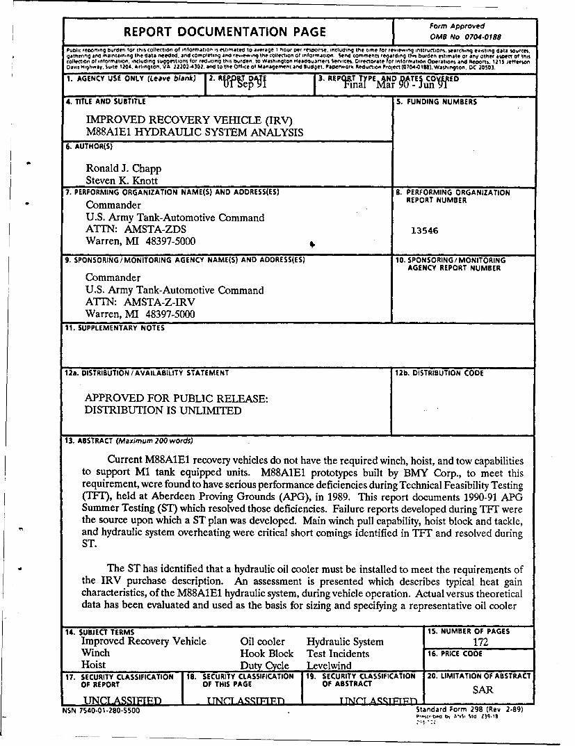
Current M88A1E1 recovery vehicles do not have the required winch, hoist, and tow capabilitiesto support M1 tank equipped units. M88A1E1 prototypes built by BMY Corp., to meet thisrequirement, were found to have serious performance deficiencies during Technical Feasibility Testing(TFT), held at Aberdeen Proving Grounds (APG), in 1989. This report documents 1990-91 APGSummer Testing (ST) which resolved those deficiencies. Failure reports developed during TFT werethe source upon which a ST plan was developed. Main winch pull capability, hoist block and tackle,and hydraulic system overheating were critical short comings identified in TFT and resolved duringST.
The ST has identified that a hydraulic oil cooler must be installed to meet the requirements ofthe IRV purchase description. An assessment is presented which describes typical heat gaincharacteristics, of the M88A1E1 hydraulic system, during vehicle operation. Actual versus theoreticaldata has been evaluated and used as the basis for sizing and specifying a representative oil cooler
14. SUBJECT TERMS '15. NUMBER OF PAGESImproved Recovery Vehicle Oil cooler Hydraulic System 172Winch Hook Block Test Incidents 16. PRICE CODEHoist Duty Cycle Levelwind
17. SECURITY CLASSIFICATION 18. SECURITY CLASSIFICATION 19. SECURITY CLASSIFICATION 20. LIMITATION OF ABSTRACTOF REPORT OF THIS PAGE OF ABSTRACT SARUNCLASSIFIED I TTN .TAA RTFITT' TTNTT Aq•qT1T'Pr) I
NSN 7540-01-280-5500 Standard Form 298 (Rev 2-89)P,,cb.d b, -°S, Sid 139.16
b
ii
IMPROVED RECOVERY VEHICLE (IRV)
M88A1E1 HYDRAULIC SYSTEM ANALYSIS
March 1990 thru June 1991
Prepared by:SYSTEMS ENGINEERS
RONALD J. CHAPPSTEVEN K. KNOTT
U.S. ARMY TANK-AUTOMOTIVE COMMAND (TACOM)
RESEARCH, DEVELOPMENT and ENGINEERING CENTER
EMERGING SYSTEMS DIVISION (AMSTA-ZD)
WARREN, MICHIGAN 48397-5000
iv
TABLE of CONTENTS
Section Page
1.0. INTRODUCTION ........................................ 1
2.0. OBJECTIVE ............................................ 2
3.0. CONCLUSION ........................................... 2
4.0. RECOMMENDATIONS .................................... 3
4.1. H oist .................... t# ........................ 3
4.2. W inch ............................................. 3
5.0. D ISCU SSION ............................................ 4
5.1. Background ......................................... 4
5.2. M88A1E1 Hydraulic Functions ........................... 5
5.2.1. Main/Auxiliary W inch ........................... 5
5.2.2. H oist W inch .................................. 8
5.2.3. Ancillary Tools ................................ 9
5.3. A PG Test .......................................... 9
5.3.1. Stall Load Testing ............................. 11
5.3.2. W inch Testing ............................... 16
5.3.3. H oist Testing ................................ 22
5.3.4. Auxiliary Winch Test .......................... 27
5.3.5. Duty Cycle Testing ............................ 28
5.4. Test Analysis ....................................... 28
5.4.1. Three-Pump System ........................... 30
5.4.2. Hydraulic Oil Cooler ........................... 32
V
TABLE of CONTENTS cont'd
Section Page
APPENDIX A Program Personnel .............................. A-1
APPENDIX B Major Test Incident Reports ....................... B-1
APPENDIX C 1990 Summer Test Directive ....................... C-1
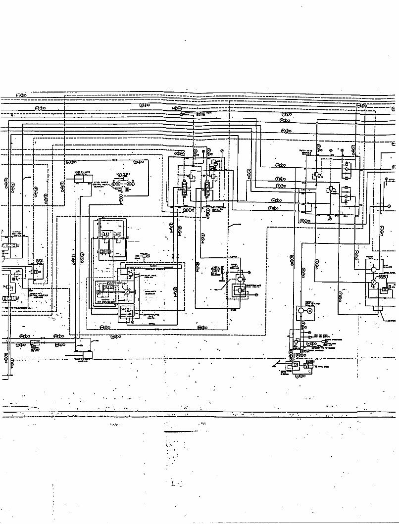
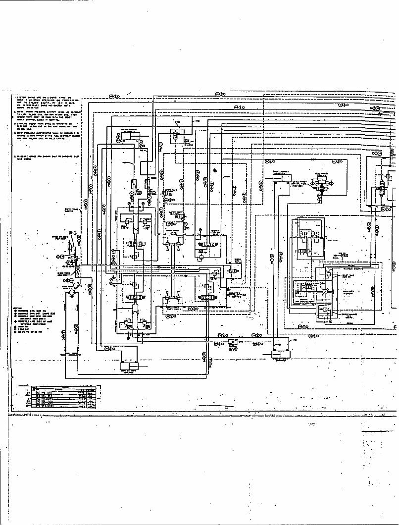
APPENDIX D Hydraulic System Diagram ........................ D-1
APPENDIX E Test Instrumentation ...... . ...................... E-1
APPENDIX F Summer Test Chronology ......................... F-1
APPENDIX G Summer Test Incidents ........................... G-1
APPENDIX H Test Data ..................................... H-1
APPENDIX I Three-Pump Modification .......................... I-1
APPENDIX J Parts List ...................................... J-1
APPENDIX K Oil Cooler .................................... K-1
DISTRIBUTION LIST .................................... DIST-1
vi
LIST of FIGURES
Figure Page
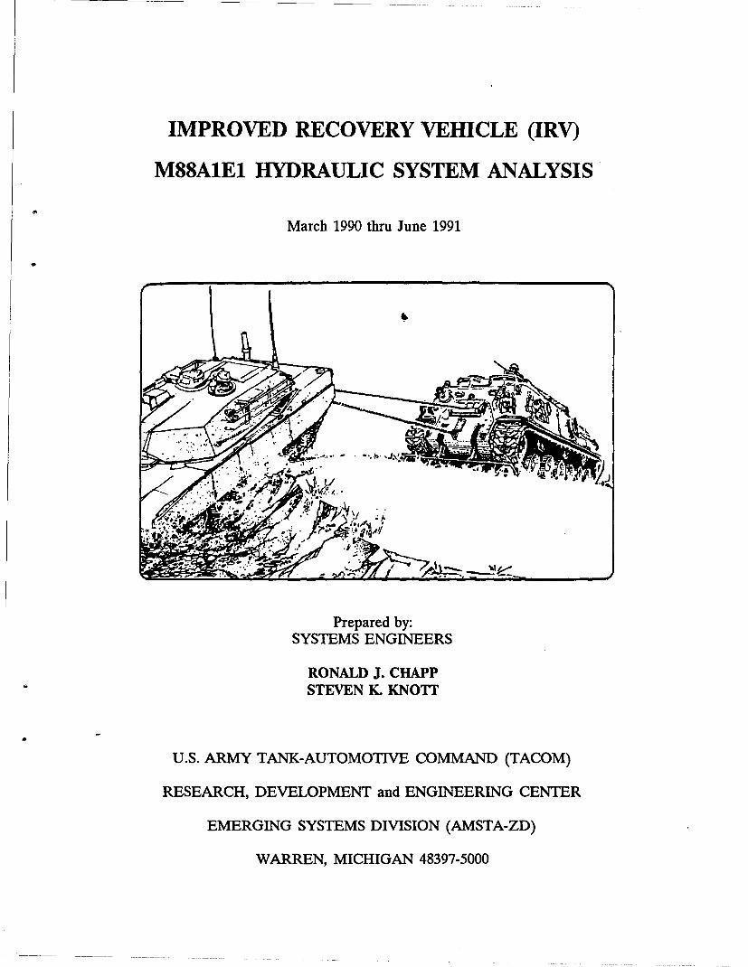
1. M88A1E1 Improved Recovery Vehicle ........................... 1
- 2. Level Wind Mechanism (Partial A) ............................. 6
3. Level Wind Mechanism (Partial B) ............................. 7
4. Level Wind Mechanism (Actual) ............................... 8
5. Layer Sense M echanism ........... o ......................... 9
6. W inching Configuration .................................... 10
7. Strengthened Level Wind Bracket ............................. 13
8. Level Wind Mechanism (Partial C) ............................ 14
9. Ground H op Kit .......................................... 14
10. Vehicle M aintenance ...................................... 15
11. Fleet Angle Switches ...................................... 16
12. Miswrap Safety Features .................................... 17
13. D PO CV ............................................... 18
14. DPOCV Installation ....................................... 19
15. Level W ind Lag .......................................... 20
16. Birds Nested and Kinked Cable ............................... 22
17. H ousing Fracture ......................................... 23
18. H oist Test Setup ......................................... 24
19. BMY Hook Block ........................................ 25
20. Boom Sheave and Deadman ................................. 25
21. Cable Twist ............................................. 26
vii
LIST of FIGURES cont'd
Figre Page
22. Relocated Deadman ....................................... 27
23. H oist Test .............................................. 29
24. Winch Test .............................................. 30
25. New Hook Block ......................................... 31
26. Three-Pump Assembly ............ 1 ........................ 32
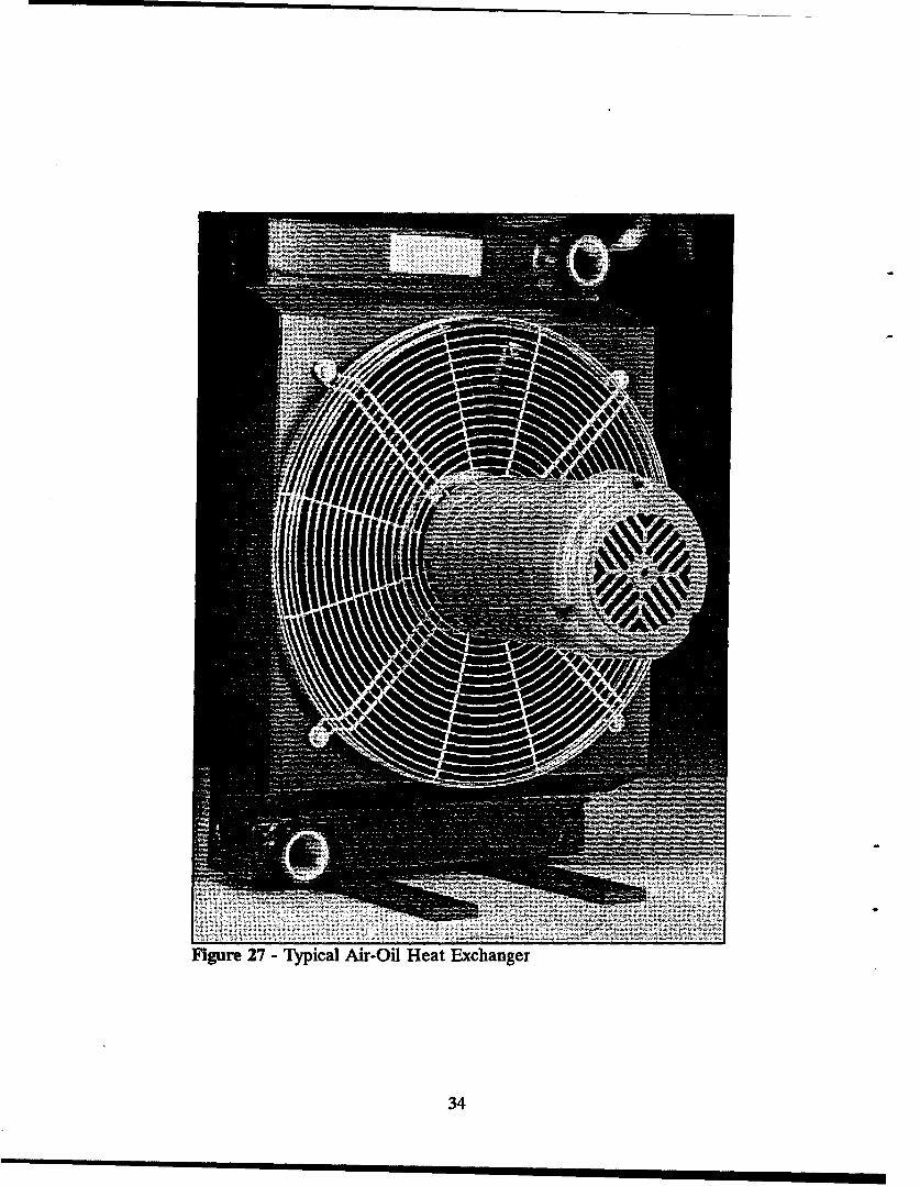
27. Typical Air-Oil Heat Exchanger .............................. 34
viii
LIST of TABLES cont'd
Table Pae
1. Stall Load D ata .......................................... 12
ix
x
1.0. INTRODUCTION
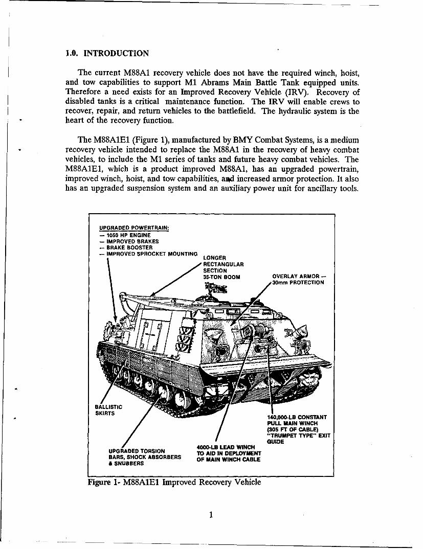
The current M88A1 recovery vehicle does not have the required winch, hoist,and tow capabilities to support M1 Abrams Main Battle Tank equipped units.Therefore a need exists for an Improved Recovery Vehicle (IRV). Recovery ofdisabled tanks is a critical maintenance function. The IRV will enable crews torecover, repair, and return vehicles to the battlefield. The hydraulic system is theheart of the recovery function.
The M88A1E1 (Figure 1), manufactured by BMY Combat Systems, is a mediumrecovery vehicle intended to replace the M88A1 in the recovery of heavy combatvehicles, to include the M1 series of tanks and future heavy combat vehicles. TheM88A1E1, which is a product improved M88A1, has an upgraded powertrain,improved winch, hoist, and tow capabilities, a.d increased armor protection. It alsohas an upgraded suspension system and an auxiliary power unit for ancillary tools.
UPGRADED POWERTRAIN:- 1050 HP ENGINE- IMPROVED BRAKES- BRAKE BOOSTER- IMPROVED SPROCKET MOUNTING LONGER
RECTANGULAR~SECTION35.TON BOOM OVERLAY ARMOR --S,30mm PROTECTION
SKIRTS //140,000-LB CONSTANT
PULL MAIN WINCH(305 FT OF CABLE)"TRUMPET TYPE" EXITGUIDE
4000-LB LEAD WINCHUPGRADED TORSION TO AID IN DEPLOYMENTBARS, SHOCK ABSORBERS OF MAIN WINCH CABLE& SNUBBERS
Figure 1- M88A1E1 Improved Recovery Vehicle
1
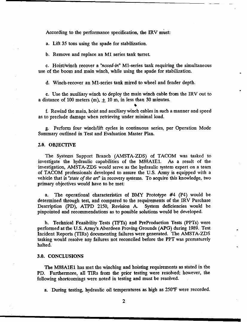
According to the performance specification, the IRV must:
a. Lift 35 tons using the spade for stabilization.
b. Remove and replace an M1 series tank turret.
c. Hoist/winch recover a "nosed-in" Ml-series tank requiring the simultaneoususe of the boom and main winch, while using the spade for stabilization.
d. Winch-recover an Ml-series tank mired to wheel and fender depth.
e. Use the auxiliary winch to deploy the main winch cable from the IRV out toa distance of 100 meters (m), + 10 m, in less than 30 minutes.
f. Rewind the main, hoist and auxiliary winch cables in such a manner and speedas to preclude damage when retrieving under minimal load.
g. Perform four winch/lift cycles in continuous series, per Operation ModeSummary outlined in Test and Evaluation Master Plan.
2.0. OBJECTIVE
The Systems Support Branch (AMSTA-ZDS) of TACOM was tasked toinvestigate the hydraulic capabilities of the M88AIE1. As a result of theinvestigation, AMSTA-ZDS would serve as the hydraulic system expert on a teamof TACOM professionals developed to assure the U.S. Army is equipped with avehicle that is "state of the art" in recovery systems. To acquire this knowledge, twoprimary objectives would have to be met:
a. The operational characteristics of BMY Prototype #4 (P4) would bedetermined through test, and compared to the requirements of the IRV PurchaseDescription (PD), ATPD 2150, Revision A. System deficiencies would bepinpointed and recommendations as to possible solutions would be developed.
b. Technical Feasibility Tests (TFTs) and PreProduction Tests (PPTs) wereperformed at the U.S. Army's Aberdeen Proving Grounds (APG) during 1989. TestIncident Reports (TIRs) documenting failures were generated. The AMSTA-ZDStasking would resolve any failures not reconciled before the PPT was prematurelyhalted.
3.0. CONCLUSIONS
The M88A1E1 has met the winching and hoisting requirements as stated in thePD. Furthermore, all TIRs from the prior testing were resolved; however, thefollowing shortcomings were noted in testing and must be resolved.
a. During testing, hydraulic oil temperatures as high as 250°F were recorded.
2
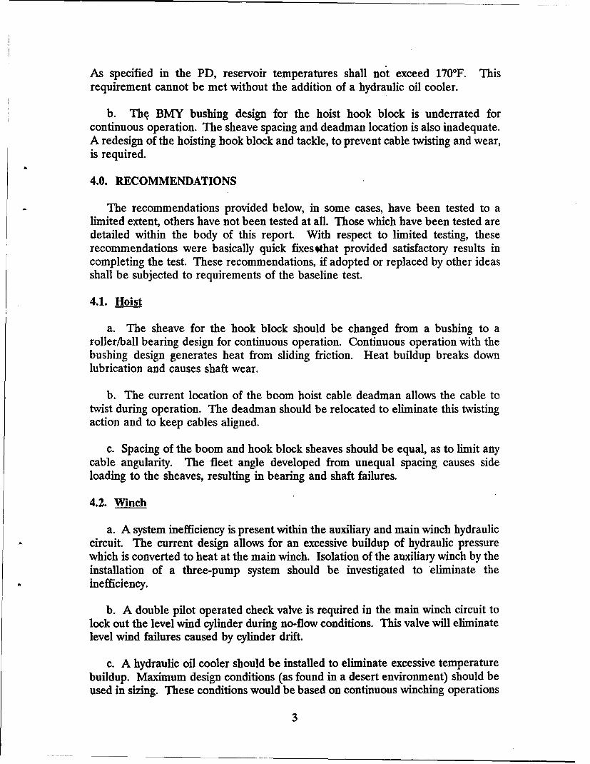
As specified in the PD, reservoir temperatures shall not exceed 170°F. Thisrequirement cannot be met without the addition of a hydraulic oil cooler.
b. Thq BMY bushing design for the hoist hook block is underrated forcontinuous operation. The sheave spacing and deadman location is also inadequate.A redesign of the hoisting hook block and tackle, to prevent cable twisting and wear,is required.
4.0. RECOMMENDATIONS
The recommendations provided below, in some cases, have been tested to alimited extent, others have not been tested at all. Those which have been tested aredetailed within the body of this report. With respect to limited testing, theserecommendations were basically quick fixes tthat provided satisfactory results incompleting the test. These recommendations, if adopted or replaced by other ideasshall be subjected to requirements of the baseline test.
4.1. Hoist
a. The sheave for the hook block should be changed from a bushing to aroller/ball bearing design for continuous operation. Continuous operation with thebushing design generates heat from sliding friction. Heat buildup breaks downlubrication and causes shaft wear.
b. The current location of the boom hoist cable deadman allows the cable totwist during operation. The deadman should be relocated to eliminate this twistingaction and to keep cables aligned.
c. Spacing of the boom and hook block sheaves should be equal, as to limit anycable angularity. The fleet angle developed from unequal spacing causes sideloading to the sheaves, resulting in bearing and shaft failures.
4.2. Winch
a. A system inefficiency is present within the auxiliary and main winch hydrauliccircuit. The current design allows for an excessive buildup of hydraulic pressurewhich is converted to heat at the main winch. Isolation of the auxiliary winch by theinstallation of a three-pump system should be investigated to eliminate theinefficiency.
b. A double pilot operated check valve is required in the main winch circuit tolock out the level wind cylinder during no-flow conditions. This valve will eliminatelevel wind failures caused by cylinder drift.
c. A hydraulic oil cooler should be installed to eliminate excessive temperaturebuildup. Maximum design conditions (as found in a desert environment) should beused in sizing. These conditions would be based on continuous winching operations
3
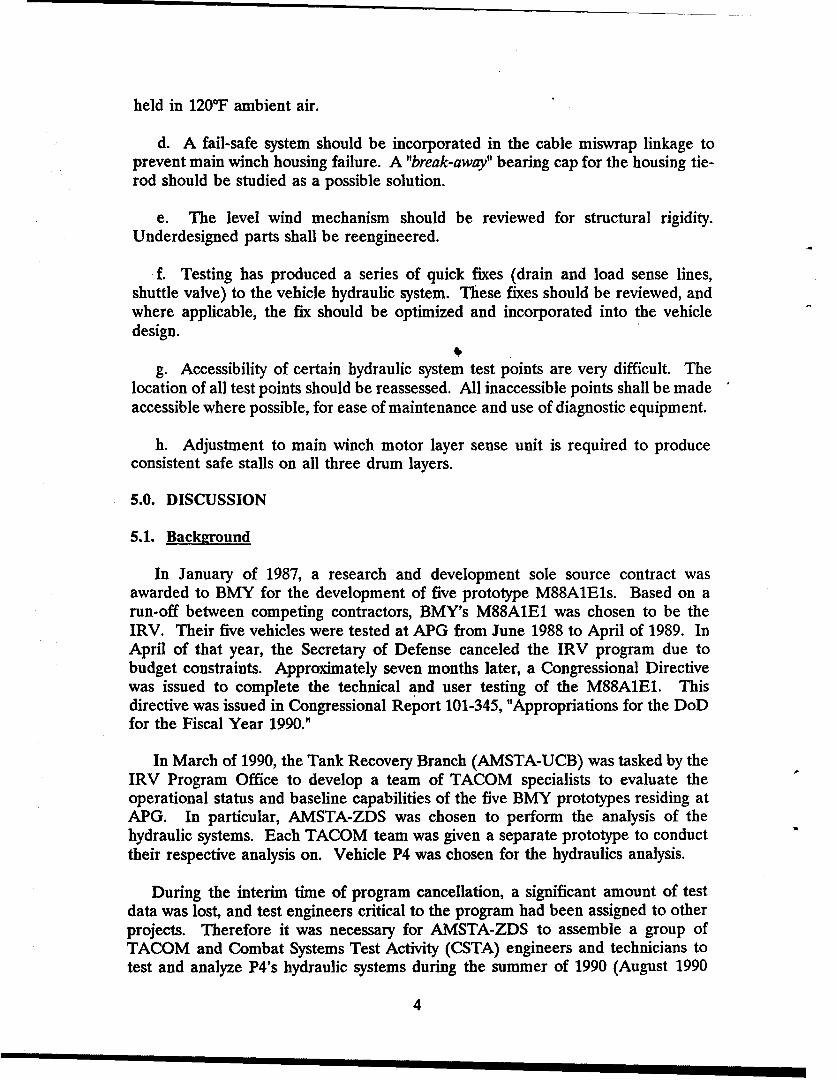
held in 120'F ambient air.
d. A fail-safe system should be incorporated in the cable miswrap linkage toprevent main winch housing failure. A "break-away" bearing cap for the housing tie-rod should be studied as a possible solution.
e. The level wind mechanism should be reviewed for structural rigidity.Underdesigned parts shall be reengineered.
L f. Testing has produced a series of quick fixes (drain and load sense lines,shuttle valve) to the vehicle hydraulic system. These fixes should be reviewed, andwhere applicable, the fix should be optimized and incorporated into the vehicledesign.
b.
g. Accessibility of certain hydraulic system test points are very difficult. Thelocation of all test points should be reassessed. All inaccessible points shall be madeaccessible where possible, for ease of maintenance and use of diagnostic equipment.
h. Adjustment to main winch motor layer sense unit is required to produce
consistent safe stalls on all three drum layers.
5.0. DISCUSSION
5.1. Background
In January of 1987, a research and development sole source contract wasawarded to BMY for the development of five prototype M88A1E1s. Based on arun-off between competing contractors, BMY's M88A1E1 was chosen to be theIRV. Their five vehicles were tested at APG from June 1988 to April of 1989. InApril of that year, the Secretary of Defense canceled the IRV program due tobudget constraints. Approximately seven months later, a Congressional Directivewas issued to complete the technical and user testing of the M88A1E1. Thisdirective was issued in Congressional Report 101-345, "Appropriations for the DoDfor the Fiscal Year 1990."
In March of 1990, the Tank Recovery Branch (AMSTA-UCB) was tasked by theIRV Program Office to develop a team of TACOM specialists to evaluate theoperational status and baseline capabilities of the five BMY prototypes residing atAPG. In particular, AMSTA-ZDS was chosen to perform the analysis of thehydraulic systems. Each TACOM team was given a separate prototype to conducttheir respective analysis on. Vehicle P4 was chosen for the hydraulics analysis.
During the interim time of program cancellation, a significant amount of testdata was lost, and test engineers critical to the program had been assigned to otherprojects. Therefore it was necessary for AMSTA-ZDS to assemble a group ofTACOM and Combat Systems Test Activity (CSTA) engineers and technicians totest and analyze P4's hydraulic systems during the summer of 1990 (August 1990
4
through March 1991). A list of team members is provided in Appendix A.
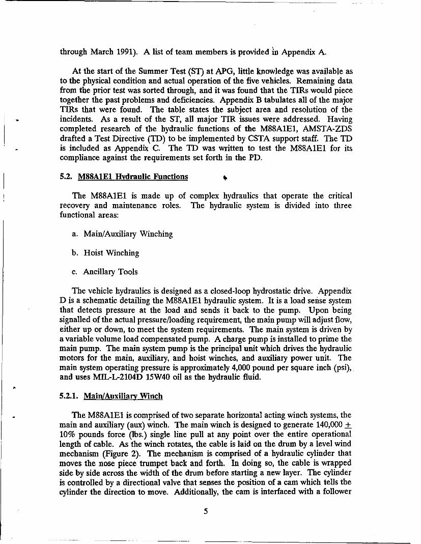
At the start of the Summer Test (ST) at APG, little knowledge was available asto the physical condition and actual operation of the five vehicles. Remaining datafrom the prior test was sorted through, and it was found that the TIRs would piecetogether the past problems and deficiencies. Appendix B tabulates all of the majorTIRs that were found. The table states the subject area and resolution of theincidents. As a result of the ST, all major TIR issues were addressed. Havingcompleted research of the hydraulic functions of the M88A1E1, AMSTA-ZDSdrafted a Test Directive (TD) to be implemented by CSTA support staff. The TDis included as Appendix C. The TD was written to test the M88A1E1 for itscompliance against the requirements set forth in the PD.
5.2. M88AIE1 Hydraulic Functions
The M88A1E1 is made up of complex hydraulics that operate the criticalrecovery and maintenance roles. The hydraulic system is divided into threefunctional areas:
a. Main/Auxiliary Winching
b. Hoist Winching
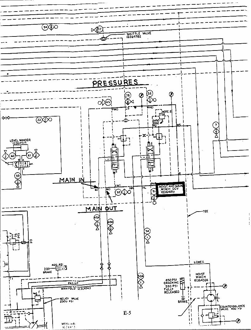
c. Ancillary Tools
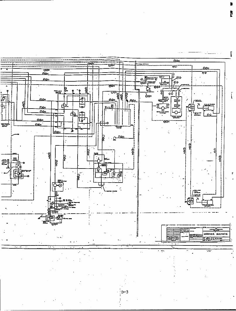
The vehicle hydraulics is designed as a closed-loop hydrostatic drive. AppendixD is a schematic detailing the M88A1E1 hydraulic system. It is a load sense systemthat detects pressure at the load and sends it back to the pump. Upon beingsignalled of the actual pressure/loading requirement, the main pump will adjust flow,either up or down, to meet the system requirements. The main system is driven bya variable volume load compensated pump. A charge pump is installed to prime themain pump. The main system pump is the principal unit which drives the hydraulicmotors for the main, auxiliary, and hoist winches, and auxiliary power unit. Themain system operating pressure is approximately 4,000 pound per square inch (psi),and uses MIL-L-2104D 15W40 oil as the hydraulic fluid.
5.2.1. Mai/Auxiliary Winch
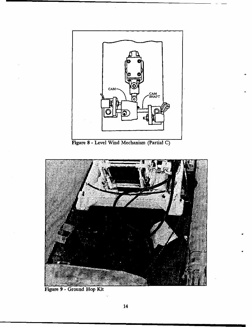
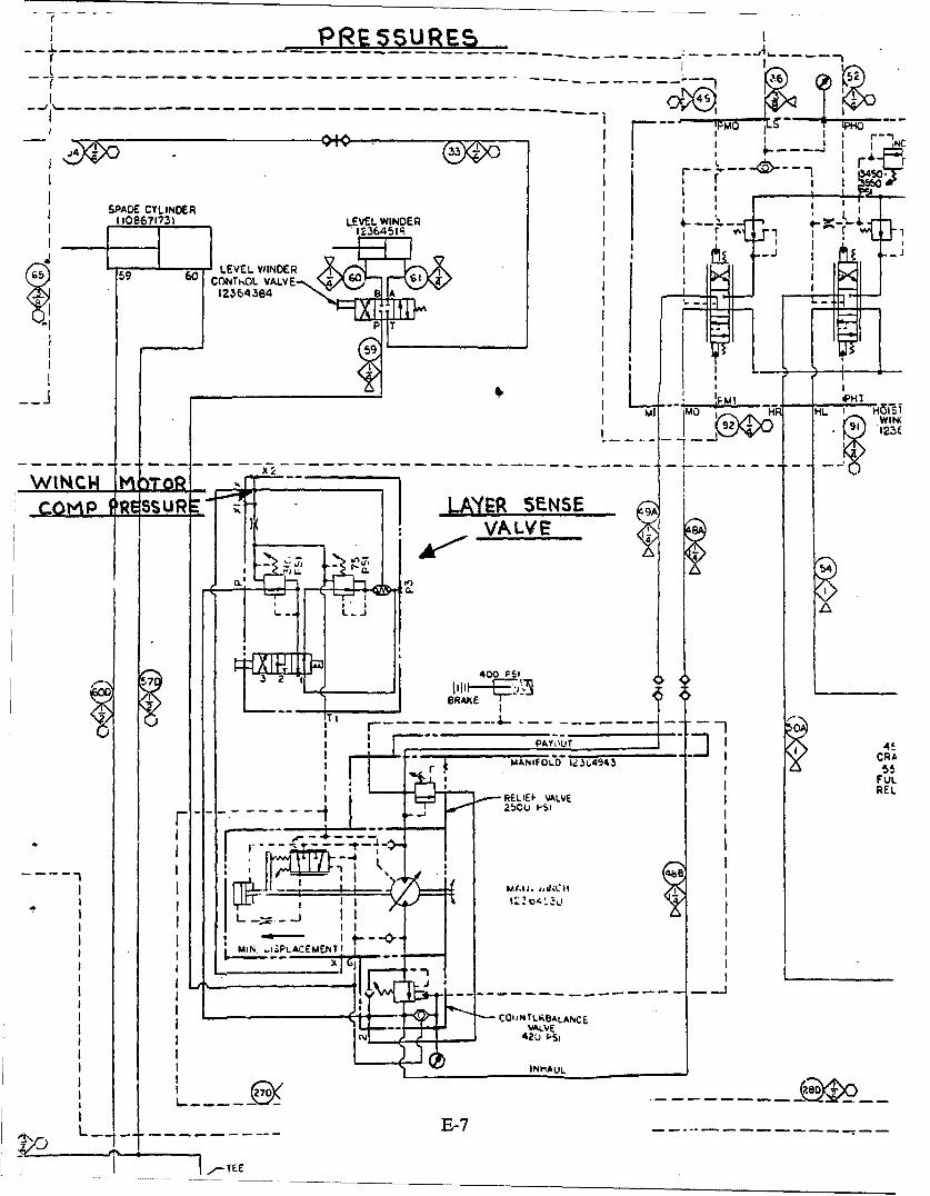
The M88A1E1 is comprised of two separate horizontal acting winch systems, themain and auxiliary (aux) winch. The main winch is designed to generate 140,000 +10% pounds force (lbs.) single line pull at any point over the entire operationallength of cable. As the winch rotates, the cable is laid on the drum by a level windmechanism (Figure 2). The mechanism is comprised of a hydraulic cylinder thatmoves the nose piece trumpet back and forth. In doing so, the cable is wrappedside by side across the width of the drum before starting a new layer. The cylinderis controlled by a directional valve that senses the position of a cam which tells thecylinder the direction to move. Additionally, the cam is interfaced with a follower
5
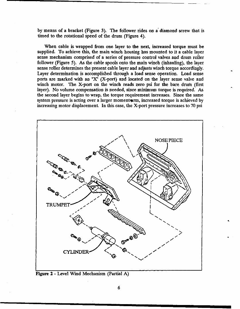
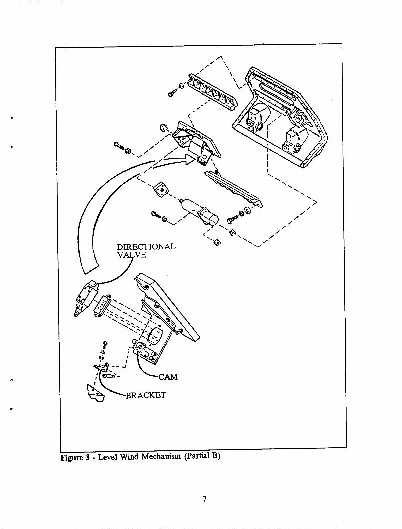
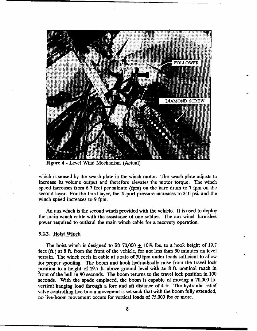
by means of a bracket (Figure 3). The follower rides on a' diamond screw that istimed to the rotational speed of the drum (Figure 4).
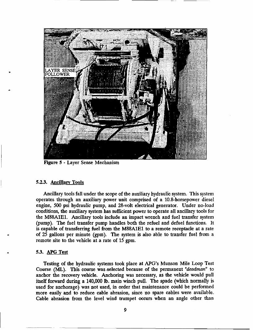
When cable is wrapped from one layer to the next, increased torque must besupplied. To achieve this, the main winch housing has mounted to it a cable layersense mechanism comprised of a series of pressure control valves and drum rollerfollower (Figure 5). As the cable spools onto the main winch (inhauling), the layersense roller determines the present cable layer and adjusts winch torque accordingly.Layer determination is accomplished through a load sense operation. Load senseports are marked with an "X' (X-port) and located on the layer sense valve andwinch motor. The X-port on the winch reads zero psi for the bare drum (firstlayer). No volume compensation is needed, since minimum torque is required. Asthe second layer begins to wrap, the torque requirement increases. Since the samesystem pressure is acting over a larger momentorm, increased torque is achieved byincreasing motor displacement. In this case, the X-port pressure increases to 70 psi
: \\NOSEPIECE
- -
N -
Figure 2 - Level Wind Mechanism (Partial A)
6
>
CAM
- \
RAKE
FiguDRETINA 3~~ -Leve WidMcaim-P~lB
V7V
\ N
III I
g CAM
,, ,(BR..---E-T
Figure 3 - Level Wind Mechanism (Partial B)
7
SFOLLOW ;IN
DIAMOND SCREW
Figure 4 - Level Wind Mechanism (Actual)
which is sensed by the swash plate in the winch motor. The swash plate adjusts toincrease its volume output and therefore elevates the motor torque. The winchspeed increases from 6.7 feet per minute (fpm) on the bare drum to 7 fpm on thesecond layer. For the third layer, the X-port pressure increases to 310 psi, and thewinch speed increases to 9 fpm.
An aux winch is the second winch provided with the vehicle. It is used to deploythe main winch cable with the assistance of one soldier. The aux winch furnishespower required to outhaul the main winch cable for a recovery operation.
5.2.2. Hoist Winch
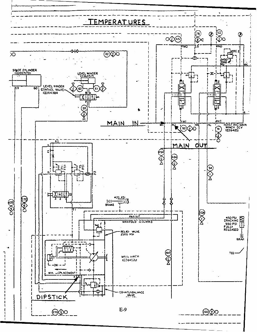
The hoist winch is designed to lift 70,000 + 10% lbs. to a hook height of 19.7feet (ft.) at 8 ft. from the front of the vehicle, for not less than 30 minutes on levelterrain. The winch reels in cable at a rate of 30 fpm under loads sufficient to allowfor proper spooling. The boom and hook hydraulically raise from the travel lockposition to a height of 19.7 ft. above ground level with an 8 ft. nominal reach infront of the hull in 90 seconds. The boom returns to the travel lock position in 100seconds. With the spade emplaced, the boom is capable of moving a 70,000 lb.vertical hanging load through a fore and aft distance of 4 ft. The hydraulic reliefvalve controlling live-boom movement is set such that with the boom fully extended,no live-boom movement occurs for vertical loads of 75,000 lbs or more.
8
LAYER SENSEFOLLOWE
Figure 5 - Layer Sense Mechanism
5.2.3. Ancillary Tools
Ancillary tools fall under the scope of the auxiliary hydraulic system. This systemoperates through an auxiliary power unit comprised of a 10.8-horsepower dieselengine, 500 psi hydraulic pump, and 28-volt electrical generator. Under no-loadconditions, the auxiliary system has sufficient power to operate all ancillary tools forthe M88A1E1. Ancillary tools include an impact wrench and fuel transfer system(pump). The fuel transfer pump handles both the refuel and defuel functions. Itis capable of transferring fuel from the M88A1E1 to a remote receptacle at a rateof 25 gallons per minute (gpm). The system is also able to transfer fuel from aremote site to the vehicle at a rate of 15 gpm.
5.3. APG Test
Testing of the hydraulic systems took place at APG's Munson Mile Loop TestCourse (ML). This course was -selected because of the permanent "deadman" toanchor the recovery vehicle. Anchoring was necessary, as the vehicle would pullitself forward during a 140,000 lb. main winch pull. The spade (which normally isused for anchorage) was not used, in order that maintenance could be performedmore easily and to reduce cable abrasion, since no spare cables were available.Cable abrasion from the level wind trumpet occurs when an angle other than
9
horizontal, between the recovery and disabled vehicles, is encountered. Theproblem is worse when the vehicle is on its spade on hard terrain.
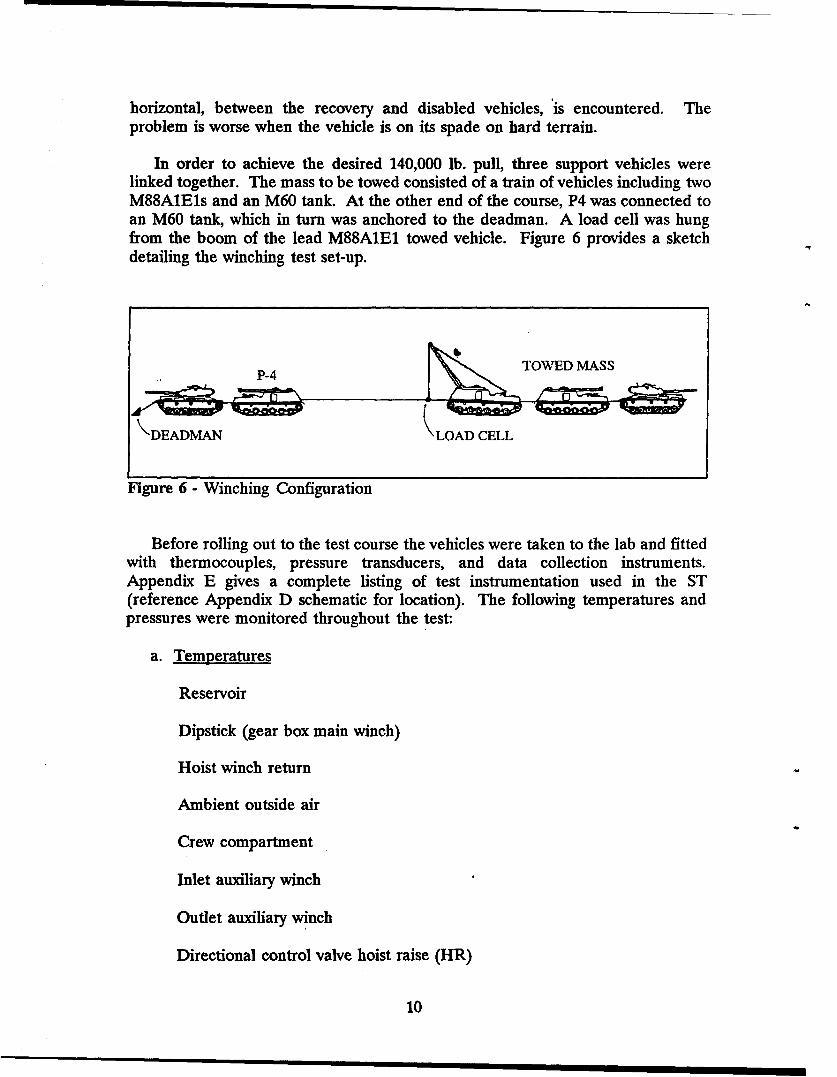
In order to achieve the desired 140,000 lb. pull, three support vehicles werelinked together. The mass to be towed consisted of a train of vehicles including twoM88A1E1s and an M60 tank. At the other end of the course, P4 was connected toan M60 tank, which in turn was anchored to the deadman. A load cell was hungfrom the boom of the lead M88A1E1 towed vehicle. Figure 6 provides a sketchdetailing the winching test set-up.
P-4 TOWED MASS
Ký"DEADMAN \LOAD CELL
Figure 6 - Winching Configuration
Before rolling out to the test course the vehicles were taken to the lab and fittedwith thermocouples, pressure transducers, and data collection instruments.Appendix E gives a complete listing of test instrumentation used in the ST(reference Appendix D schematic for location). The following temperatures andpressures were monitored throughout the test:
a. Temperatures
Reservoir
Dipstick (gear box main winch)
Hoist winch return
Ambient outside air
Crew compartment
Inlet auxiliary winch
Outlet auxiliary winch
Directional control valve hoist raise (HR)
10
Directional control valve hoist lower (HL)
Directional control valve main input (MI)
Directional control valve main output (MO)
b. Pressures
Charge pump
Main pump compensation
Main pump
X-port main winch
Directional control valve main input (MI)
Directional control valve main output (MO)
With all the instrumentation and measurement equipment in place; aninitialization and check of the test equipment commenced. After ten minutes ofengine idle, a hydraulic line used in the measurement of the main system pressureburst. A full-force hydraulic oil stream struck a TACOM engineer in the chest.Fortunately, the start-up pressure of 1500 psi and oil temperature of 87°F were lowenough as to not cause injury. The engineer was taken to the base hospital, treated,and released. The incident was officially reported. Repairs were made to thevehicle, and the instrumentation all functioned properly.
All test vehicles were taken to the ML, and the team officially began the ST on15 Aug 90. Appendix F gives a chronology of events that occurred during the STby date. Appendix G presents a detailed table listing major ST incidents and theirrespective resolutions. The ST was broken up into four sections; stall, winch, hoist,and duty-cycle tests. Appendix H presents the detailed raw data accumulated forthe eighty-one test runs completed. The following sections describe each test.
5.3.1. Stall Load Testing
The first array of tests to be executed were stall loads. Stall loading measuresthe force required to stall (stop rotating) the main winch drum. This is a safetyfeature of the system. Without it, the winch would continue to increase its pullingforce until the fatigue strength of the cable is reached or drum, failure occurs.There are three layers of cable on the main winch drum and the moment arm isincreased as each layer of cable is added to the drum. Therefore the winch mustproduce a variable torque so a constant load can be inhauled. Table 1 lists the stallloads measured.
11
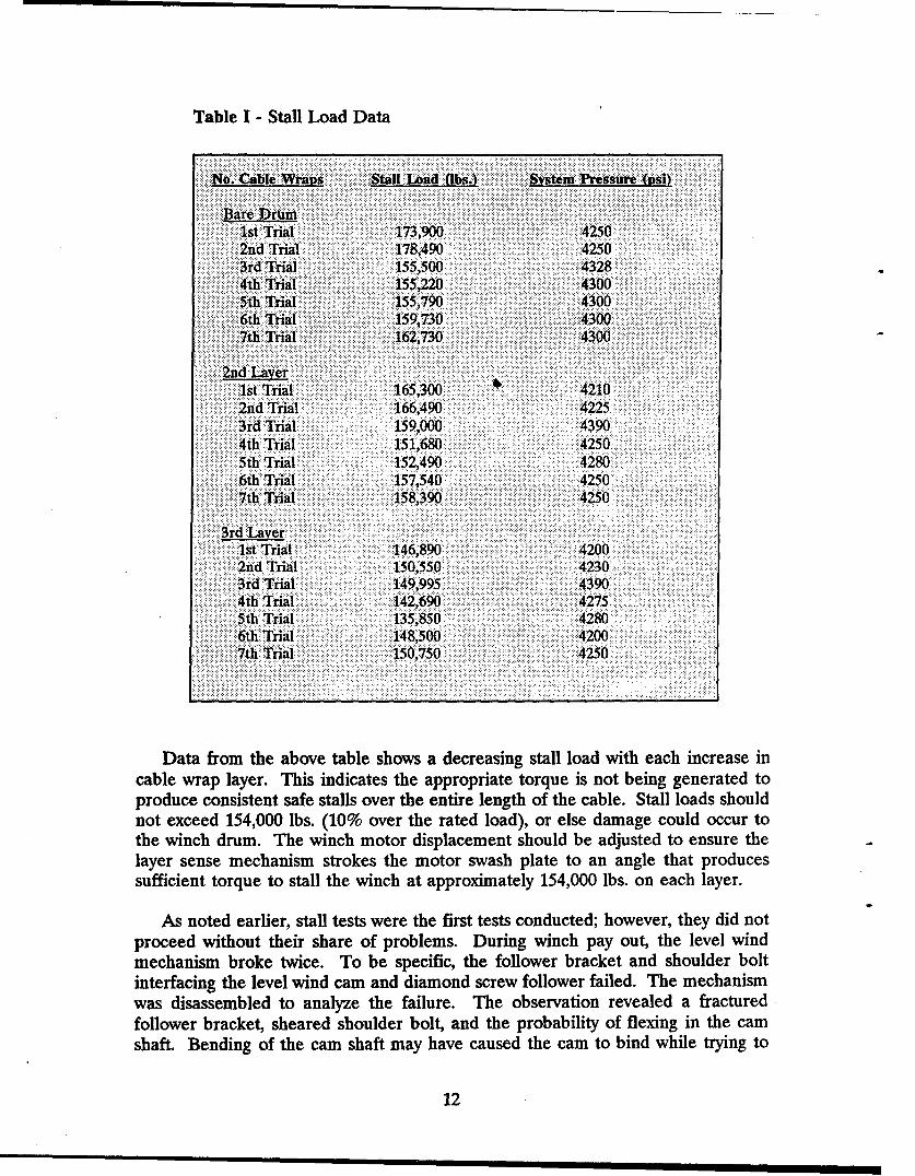
Table I - Stall Load Data
o.Cable W:Vraus Stall L"ad albsA' Sstem Pressure (si)
BaeDrum1st Trial 173,900 42502nd Trial 178,490 42503rd Trial 155,500 43284th Trial 155,220 43005th Trial 155,790 43006th Trial 1I.:59,730........4300..7th Trial ...........<o>::..x162,.730 4300
2nd Layer1st Trial ...... 165,300 .4210
:2nd Trial 166,490 42253rd Trial 159,000 43904th Trial ~ 151,680 42505th Trial 152,490 42806t Trial 157,540 4250
3rd Laver.1st Trial 1480.42002nd Trial 150,550 .4230
3rd Trial 149,995 . 43904hTrial :142,690 4275
5th Trial 135,850 . 42806hTrial 148,500 4200
7th Trial 420,70
Data from the above table shows a decreasing stall load with each increase incable wrap layer. This indicates the appropriate torque is not being generated toproduce consistent safe stalls over the entire length of the cable. Stall loads shouldnot exceed 154,000 lbs. (10% over the rated load), or else damage could occur tothe winch drum. The winch motor displacement should be adjusted to ensure thelayer sense mechanism strokes the motor swash plate to an angle that producessufficient torque to stall the winch at approximately 154,000 lbs. on each layer.
As noted earlier, stall tests were the first tests conducted; however, they did notproceed without their share of problems. During winch pay out, the level windmechanism broke twice. To be specific, the follower bracket and shoulder boltinterfacing the level wind cam and diamond screw follower failed. The mechanismwas disassembled to analyze the failure. The observation revealed a fracturedfollower bracket, sheared shoulder bolt, and the probability of flexing in the camshaft. Bending of the cam shaft may have caused the cam to bind while trying to
12
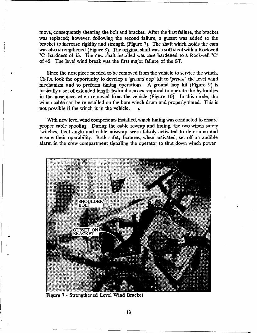
move, consequently shearing the bolt and bracket. After the first failure, the bracketwas replaced; however, following the second failure, a gusset was added to thebracket to increase rigidity and strength (Figure 7). The shaft which holds the camwas also strengthened (Figure 8). The original shaft was a soft steel with a Rockwell"C" hardness of 13. The new shaft installed was case hardened to a Rockwell "C"of 45. The level wind break was the first major failure of the ST.
Since the nosepiece needed to be removed from the vehicle to service the winch,CSTA took the opportunity to develop a "ground hop" kit to "pretest" the level windmechanism and to preform timing operations. A ground hop kit (Figure 9) isbasically a set of extended length hydraulic hoses required to operate the hydraulicsin the nosepiece when removed from the vehicle (Figure 10). In this mode, thewinch cable can be reinstalled on the bare winch drum and properly timed. This isnot possible if the winch is in the vehicle. q.
With new level wind components installed, winch timing was conducted to ensureproper cable spooling. During the cable rewrap and timing, the two winch safetyswitches, fleet angle and cable miswrap, were falsely activated to determine andensure their operability. Both safety features, when activated, set off an audiblealarm in the crew compartment signaling the operator to shut down winch power
.:::::::::::::::::::::::::::::::: ... .. . .... . ................. i i: ii i
...:::::::::::::::::::: .. . .. .... .... . .. ,.,... ....
,SHOULDER~i:i:BOLT .........................
-iGUSSET ONiBRACKET
Figure 7 - Strengthened Level Wind Bracket
13
Fiur 8-LeelWndMehnim PrtalC
Figure 8 -Ground Hopd Kehnsm(atilC
A1
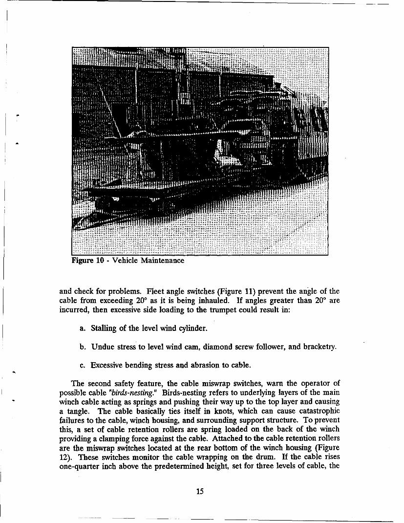
Figure 10 - Vehicle Maintenance
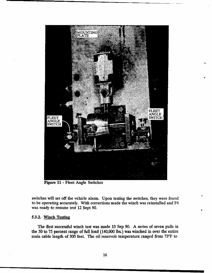
and check for problems. Fleet angle switches (Figure 11) prevent the angle of thecable from exceeding 200 as it is being inhauled. If angles greater than 200 areincurred, then excessive side loading to the trumpet could result in:
a. Stalling of the level wind cylinder.
b. Undue stress to level wind cam, diamond screw follower, and bracketry.
c. Excessive bending stress and abrasion to cable.
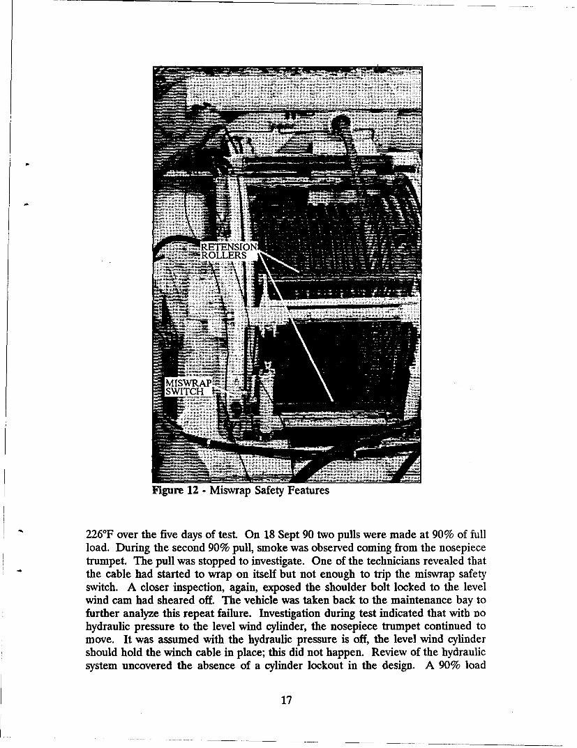
The second safety feature, the cable miswrap switches, warn the operator ofpossible cable "birds-nesting." Birds-nesting refers to underlying layers of the mainwinch cable acting as springs and pushing their way up to the top layer and causinga tangle. The cable basically ties itself in knots, which can cause catastrophicfailures to the cable, winch housing, and surrounding support structure. To preventthis, a set of cable retention rollers are spring loaded on the back of the winchproviding a clamping force against the cable. Attached to the cable retention rollersare the miswrap switches located at the rear bottom of the winch housing (Figure12). These switches monitor the cable wrapping on the drum. If the cable risesone-quarter inch above the predetermined height, set for three levels of cable, the
15
INM
Figu.....re. -1 - Fi tches-
i _ iiii•:• iiiii! •liiFLEET
S.. ¢•i!• i::i'!!}•i:ANGLEFLEET WICHANGLE........ ... •.-SWITCH. .....
Figure 11 - Fleet Angle Switches
switches will set off the vehicle alarm. Upon testing the switches, they were foundto be operating accurately. With corrections made the winch was reinstalled and P4was ready to resume test 12 Sept 90.
5.3.2. Winch Testin2
The first successful winch test was made 13 Sep 90. A series of seven pulls inthe 50 to 75 percent range of full load (140,000 lbs.) was winched in over the entiremain cable length of 300 feet. The oil reservoir temperature ranged from 73TF to
16
"- ...... RETENSION
SWTCH
Figure 12 - Miswrap Safety Features
226°F over the five days of test. On 18 Sept 90 two pulls were made at 90% of fullload. During the second 90% pull, smoke was observed coming from the nosepiecetrumpet. The pull was stopped to investigate. One of the technicians revealed thatthe cable had started to wrap on itself but not enough to trip the miswrap safetyswitch. A closer inspection, again, exposed the shoulder bolt locked to the levelwind cam had sheared off. The vehicle was taken back to the maintenance bay tofurther analyze this repeat failure. Investigation during test indicated that with nohydraulic pressure to the level wind cylinder, the nosepiece trumpet continued tomove. It was assumed with the hydraulic pressure is off, the level wind cylindershould hold the winch cable in place; this did not happen. Review of the hydraulicsystem uncovered the absence of a cylinder lockout in the design. A 90% load
17
equates to a 126,000-lb force on the cable and during the test the cable was beinginhauled at an angle. With the load at an angle, a side load is induced (sine of theinhaul angle) forcing the level wind cylinder to either side. With the cylindermoving and the drum stationary, the bracket and shoulder bolt bridging the twotogether ultimately shears. The theory was validated by conducting several subtestsusing a portable hydraulic jack to push the trumpet back and forth with no powerto the nosepiece.
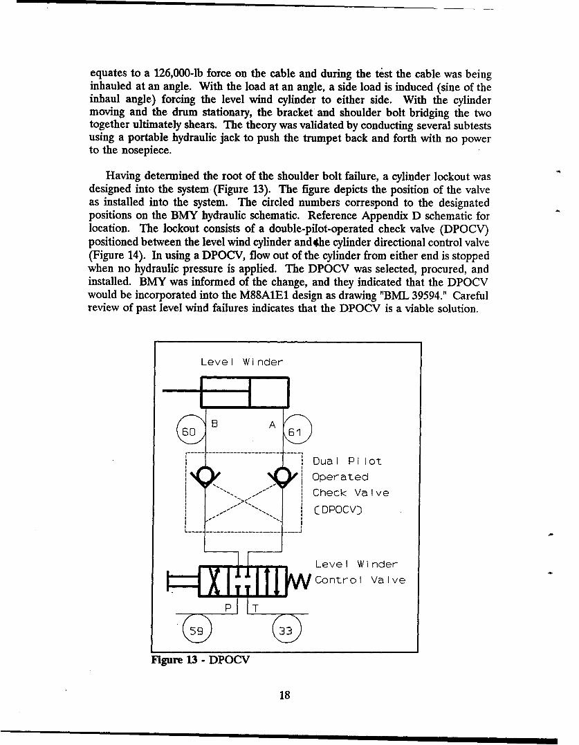
Having determined the root of the shoulder bolt failure, a cylinder lockout wasdesigned into the system (Figure 13). The figure depicts the position of the valveas installed into the system. The circled numbers correspond to the designatedpositions on the BMY hydraulic schematic. Reference Appendix D schematic forlocation. The lockout consists of a double-pilot-operated check valve (DPOCV)positioned between the level wind cylinder and 4he cylinder directional control valve(Figure 14). In using a DPOCV, flow out of the cylinder from either end is stoppedwhen no hydraulic pressure is applied. The DPOCV was selected, procured, andinstalled. BMY was informed of the change, and they indicated that the DPOCVwould be incorporated into the M88A1E1 design as drawing "BML 39594." Carefulreview of past level wind failures indicates that the DPOCV is a viable solution.
Level Winder
Dual Pilot
Operated1Check Valve
I i CDPOCVD
F Level Winder
Control Valve
Figure 13 - DPOCV
18
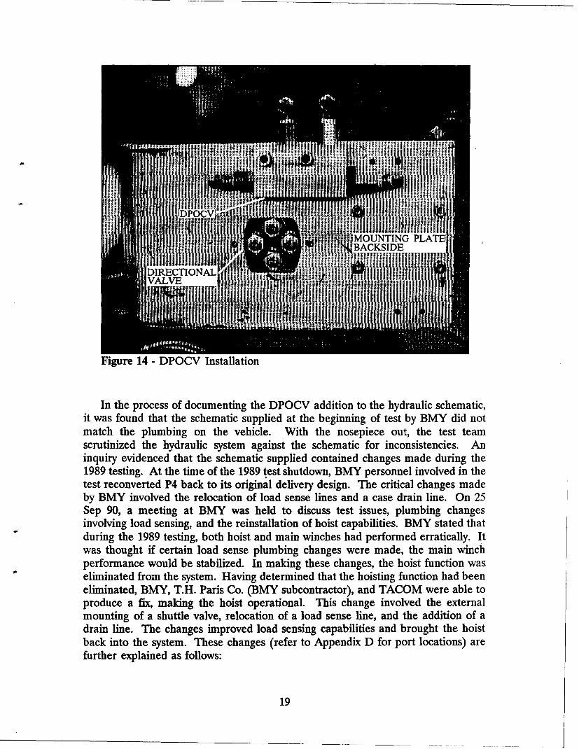
MOUNTING PLATE!BACKSIDE
DIRECTIONALVALVE
Figure 14 - DPOCV Installation
In the process of documenting the DPOCV addition to the hydraulic .schematic,it was found that the schematic supplied at the beginning of test by BMY did notmatch the plumbing on the vehicle. With the nosepiece out, the test teamscrutinized the hydraulic system against the schematic for inconsistencies. Aninquiry evidenced that the schematic supplied contained changes made during the1989 testing. At the time of the 1989 test shutdown, BMY personnel involved in thetest reconverted P4 back to its original delivery design. The critical changes madeby BMY involved the relocation of load sense lines and a case drain line. On 25Sep 90, a meeting at BMY was held to discuss test issues, plumbing changesinvolving load sensing, and the reinstallation of hoist capabilities. BMY stated thatduring the 1989 testing, both hoist and main winches had performed erratically. Itwas thought if certain load sense plumbing changes were made, the main winchperformance would be stabilized. In making these changes, the hoist function waseliminated from the system. Having determined that the hoisting function had beeneliminated, BMY, T.H. Paris Co. (BMY subcontractor), and TACOM were able toproduce a fix, making the hoist operational. This change involved the externalmounting of a shuttle valve, relocation of a load sense line, and the addition of adrain line. The changes improved load sensing capabilities and brought the hoistback into the system. These changes (refer to Appendix D for port locations) arefurther explained as follows:
19
a. Relocation of the load sense line from the hoist and main winch DCV tothe G-port of the winch motor increased load sense capability. The load was nowbeing sensed at the point of load application and not at the remote DCV.
b. Pilot pressure line between T,-port on the layer sense manifold and winchmotor was disconnected. Two separate drain lines run back to the reservoir; onefrom the T,-port, the other from the case drain running from the winch motor. Thetwo drain lines were run back to the reservoir to reduce back pressure in the winchlayer sense mechanism. This allows for better winch control. As a secondarybenefit, reducing back pressure extends the life of the winch motor seals.
c. The addition of an external shuttle valve reconnected the hoist load senseto the main pump, once again making the hoist operational. The new shuttle valvehas three ports. The first tees off the main winch motor G-port with a load senseline back to the shuttle valve (Line 36 on the schematic). The second shuttle valveport runs a load sense line to the hoist LS-port on the DCV. The third port, exitside of the valve, is routed directly to the load sense port on the main system pump.With this plumbing configuration, both hoist and winch loads are sensed. As theload increases, it is sensed directly back at the main pump. BMY and CSTApersonnel made the plumbing and valve changes at APG. Appendix I consists of arevised hydraulic schematic with updated plumbing.
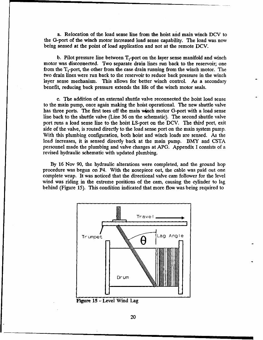
By 16 Nov 90, the hydraulic alterations were completed, and the ground hopprocedure was begun on P4. With the nosepiece out, the cable was paid out onecomplete wrap. It was noticed that the directional valve cam follower for the levelwind was riding in the extreme positions of the cam, causing the cylinder to lagbehind (Figure 15). This condition indicated that more flow was being required to
S~Trave I
Trumpet •0 1Lag Angle
Dr um
Figure 15 -Level Wind Lag
20
keep the level wind synchronous with the winch drum. Maximum in and outpositions of the valve equates to maximum valve opening. Three separate attemptsof paying the cable in and out resulted in the level wind lagging, which tripped thefleet angle switches causing the system to shut down. In order to fully open thelevel wind cylinder directional valve and supply more flow, the cam was movedcloser to the directional valve. This change resulted in a full open position for thedirectional valve. The adjustment was made by loosening the slot mounted fleetangle switch brackets and pushing them forward. As a result of this change, thefleet angle switches did not trip the vehicle alarm, and the lagging problem appearedto be solved.
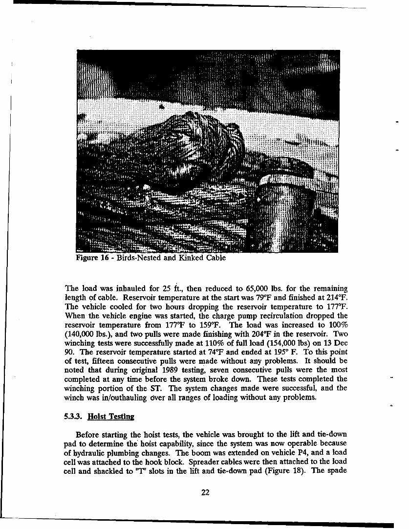
On 26 Nov 90, P4 was taken to the ML for the resumption of winch testing. Thecable was paid out only five feet, and the warning buzzer in the vehicle went off.It was concluded that the fleet angle switch monitoring the angle of cable inhaul hadbeen tripped. The cable was brought in a foot and then paid out. After anotherfifteen feet, the alarm again sounded. A visual inspection confirmed that the cablewas paying straight out, and the remaining cable appeared to be properly spooledon the drum. All preceding failures to this point of test were caused by the cablebeing in/outhauled at angles exceeding the limits set for the fleet angle switches.With this background information available, the system override switch wasdepressed to restart and continue the cable outhaul. With the cable outapproximately 50 ft., two loud bangs were heard. The vehicle was immediately shutdown, and it was discovered that the cable had birds-nested and kinked (Figure 16).This incident caused a major failure in the main winch housing. A housing tie-rodon the back of the winch was ripped away from the housing (Figure 17). Failurediagnosis revvealed that the cable miswrap warning switches were wired in the samecircuit as the level wind fleet angle switches. No indication of excessive cable anglewas noted, therefore the alarm was overridden. By overriding the alarm, the cablewas outhauled under no tension and birds-nested. A misdiagnosis of the vehiclealarm warning caused the housing failure. The winch could not be fixed due toextensive housing damage; consequently, the entire winch was removed and replacedwith the winch from vehicle R2.
Cable birds-nesting continues to be a potential problem for the M88A1E1.Although it was an operator failure, the overriding of the warning signal is asituation that could arise in the field. Should this situation occur, the potential fordamage must be minimized. The addition of breakaway bearing caps for the tie rodsis a possible solution. Future winch design should consider a fail-safe design for themain winch housing and tie rods.
With the winched replaced, P4 was again ready for test starting 11 Dec 90. Sixsuccessful payin and payout winch tests were performed at 75% (96,000 lbs.) of fullload. Four tests before noon that day resulted in a final reservoir temperature of2140F. The vehicle was allowed to cool for two hours to a reservoir temperature of167*F. The final two winch tests performed concluded with the reservoir at 204"F.On 12 Dec 90, three additional winch tests were run at 90% (126,000 lbs.) full load.
21
... .i .... .. .... . . . ... ..... .. .... . .iiiiiiiiiiiii .... ........... ................. :: ........... ...
Figure 16 - Birds-Nested and Kinked Cable
The load was inhauled for 25 ft., then reduced to 65,000 lbs. for the remaininglength of cable. Reservoir temperature at the start was 79°F and finished at 214'F.The vehicle cooled for two hours dropping the reservoir temperature to 177°F.When the vehicle engine was started, the charge pump recirculation dropped thereservoir temperature from 177°F to 159°F. The load was increased to 100%(140,000 lbs.), and two pulls were made finishing with 2040F in the reservoir. Twowinching tests were successfully made at 110% of full load (154,000 lbs) on 13 Dec90. The reservoir temperature started at 74°F and ended at 1950 F. To this pointof test, fifteen consecutive pulls were made without any problems. It should benoted that during original 1989 testing, seven consecutive pulls were the mostcompleted at any time before the system broke down. These tests completed thewinching portion of the ST. The system changes made were successful, and thewinch was in/outhauling over all ranges of loading without any problems.
5.3.3. Hoist Testing
Before starting the hoist tests, the vehicle was brought to the lift and tie-downpad to determine the hoist capability, since the system was now operable becauseof hydraulic plumbing changes. The boom was extended on vehicle P4, and a loadcell was attached to the hook block. Spreader cables were then attached to the loadcell and shackled to "T' slots in the lift and tie-down pad (Figure 18). The spade
22
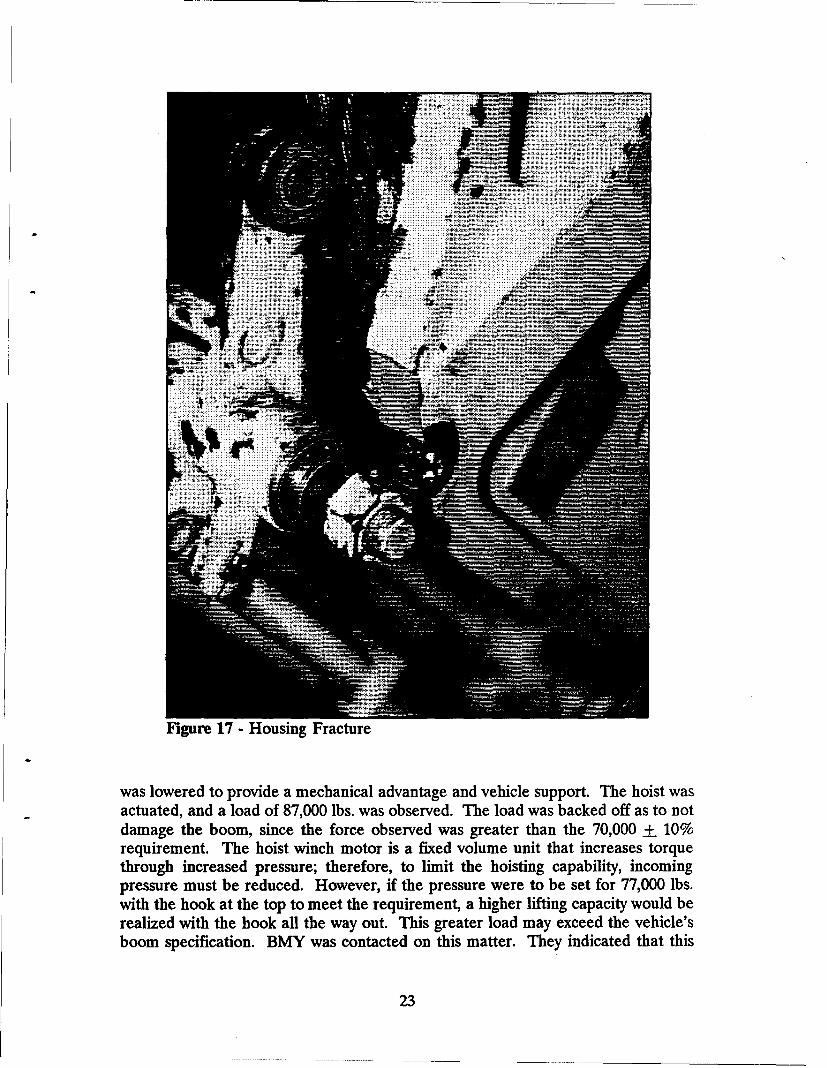
Figure 17 - Housing Fracture
was lowered to provide a mechanical advantage and vehicle support. The hoist wasactuated, and a load of 87,000 lbs. was observed. The load was backed off as to notdamage the boom, since the force observed was greater than the 70,000 + 10%requirement. The hoist winch motor is a fixed volume unit that increases torquethrough increased pressure; therefore, to limit the hoisting capability, incomingpressure must be reduced. However, if the pressure were to be set for 77,000 lbs.with the hook at the top to meet the requirement, a higher lifting capacity would berealized with the hook all the way out. This greater load may exceed the vehicle'sboom specification. BMY was contacted on this matter. They indicated that this
23
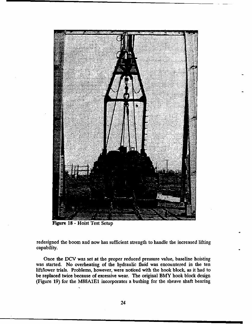
Figure 18 - Hoist Test Setup
redesigned the boom and now has sufficient strength to handle the increased liftingcapability.
Once the DCV was set at the proper reduced pressure value, baseline hoistingwas started. No overheating of the hydraulic fluid was encountered in the tenlift/lower trials. Problems, however, were noticed with the hook block, as it had tobe replaced twice because of excessive wear. The original BMY hook block design(Figure 19) for the M88A1E incorporates a bushing for the sheave shaft bearing
24
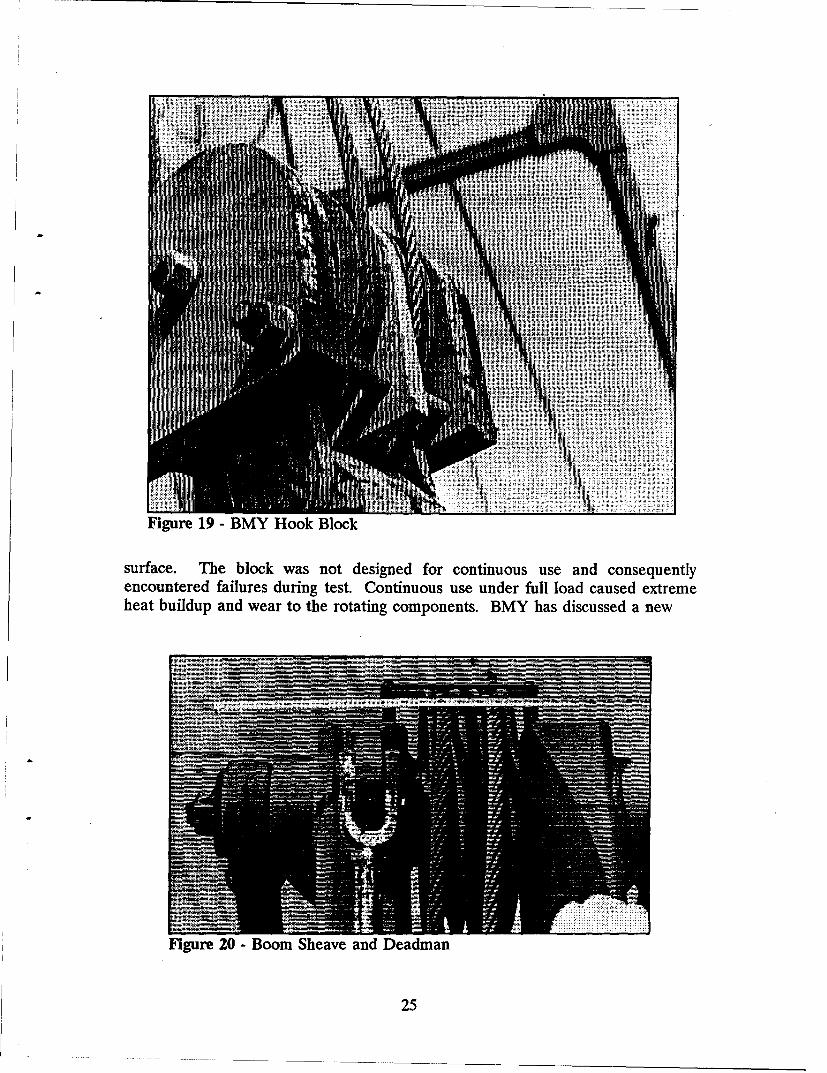
Figure 19 - BMY Hook Block
surface. The block was not designed for continuous use and consequentlyencountered failures during test. Continuous use under full load caused extremeheat buildup and wear to the rotating components. BMY has discussed a new
Figure 20 -Boom Sheave and Deadman
25
ADW
I - AND- -----
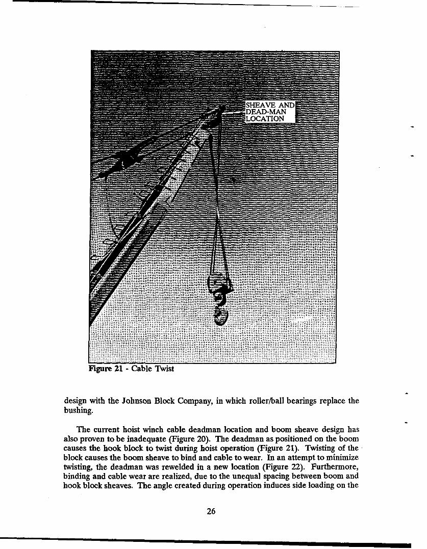
Figure 2-1 -Cable Twist
design with the Johnson Block Company, in which roller/ball bearings replace thebushing.
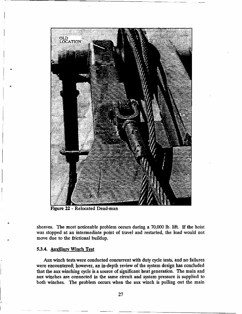
The current hoist winch cable deadman location and boom sheave design hasalso proven to be inadequate (Figure 20). The deadman as positioned on the boomcauses the hook block to twist during hoist operation (Figure 21). Twisting of the*block causes the boom sheave to bind and cable to wear. In an attempt to minimizetwisting, the deadman was rewelded in a new location (Figure 22). Furthermore,binding and cable wear are realized, due to the unequal spacing between boom andhook block sheaves. The angle created during operation induces side loading on the
26
. ... ... .... . ..... . .. . .. i =OLD
LOCATION-__
Figure 22 -Relocated Dead-man
sheaves. The most noticeable problem occurs during a 70,000 lb. lift. If the hoistwas stopped at an intermediate point of travel and restarted, the load would notmove due to the frictional buildup.
5.3.4. Auxiliary Winch Test
Aux winch tests were conducted concurrent with duty cycle tests, and no failureswere encountered; however, an in-depth review of the system design has concludedthat the aux winching cycle is a source of significant heat generation. The main andaux winches are connected in the same circuit and system pressure is supplied toboth-winches. The problem occurs when the aux winch is pulling out the main
27
winch cable. The main winch only requires 500 psi to spool during this function,while the aux demands 4,000 psi. Needing only 500 psi, the main winch pressurerelief dumps the remaining 3,500 psi directly to heat which is added to the hydraulicsystem.
5.3.5. Duty Cycle Testing
The duty cycle test had a twofold purpose:
a. The duty cycle, as defined in the PD, had never been tested during theprevious TFT and PPT. The ST would prove out the adequacy (too stringent or toosimple) of the duty cycle.
b. The data obtained from the duty cycle test would be the determining factoras to the need for a hydraulic oil cooler.
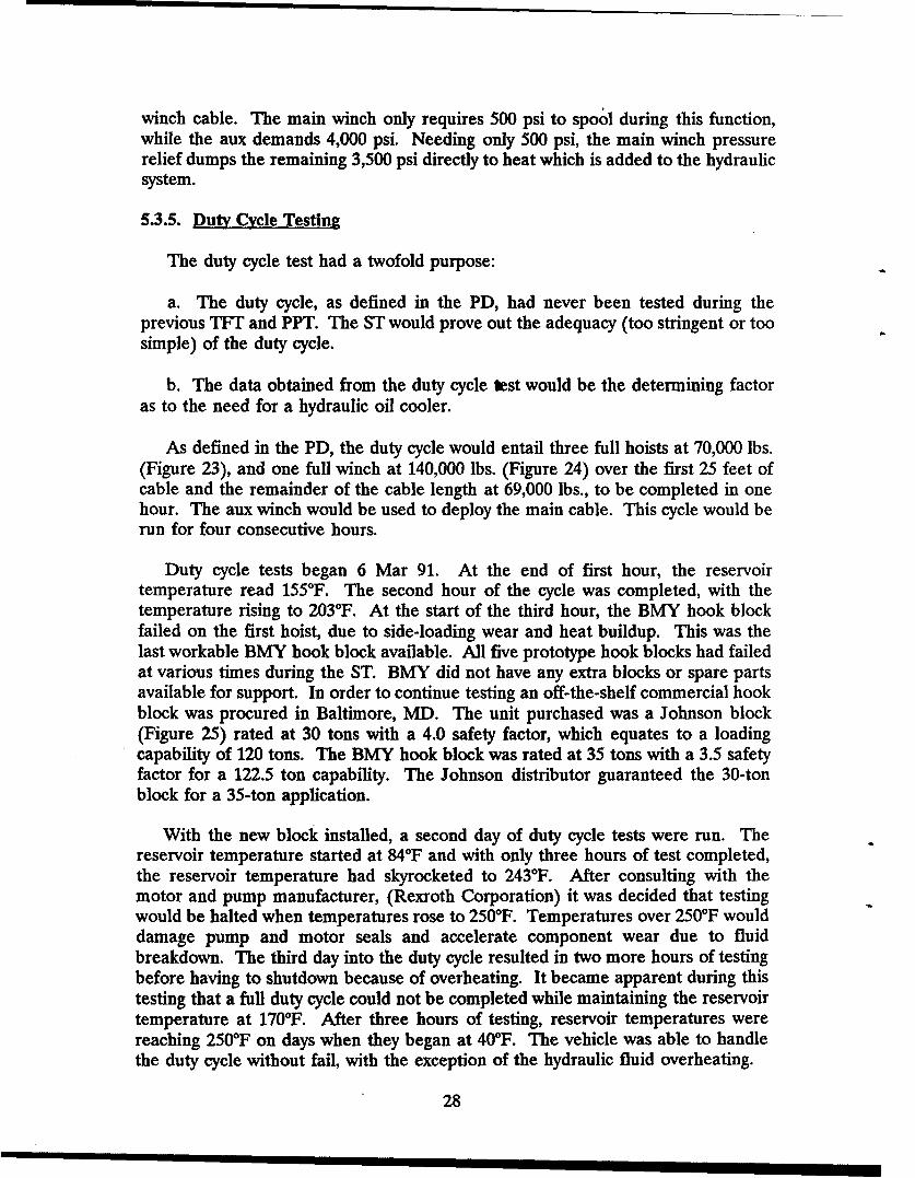
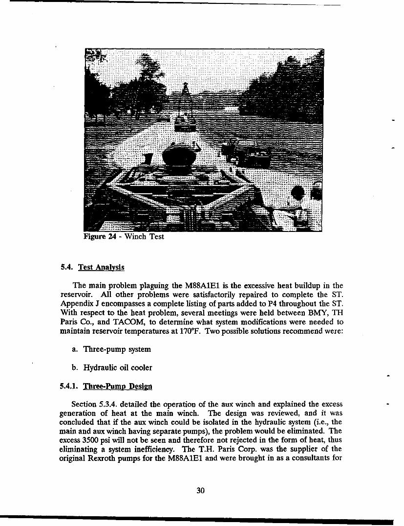
As defined in the PD, the duty cycle would entail three full hoists at 70,000 lbs.(Figure 23), and one full winch at 140,000 lbs. (Figure 24) over the first 25 feet ofcable and the remainder of the cable length at 69,000 lbs., to be completed in onehour. The aux winch would be used to deploy the main cable. This cycle would berun for four consecutive hours.
Duty cycle tests began 6 Mar 91. At the end of first hour, the reservoirtemperature read 1550F. The second hour of the cycle was completed, with thetemperature rising to 2030F. At the start of the third hour, the BMY hook blockfailed on the first hoist, due to side-loading wear and heat buildup. This was thelast workable BMY hook block available. All five prototype hook blocks had failedat various times during the ST. BMY did not have any extra blocks or spare partsavailable for support. In order to continue testing an off-the-shelf commercial hookblock was procured in Baltimore, MD. The unit purchased was a Johnson block(Figure 25) rated at 30 tons with a 4.0 safety factor, which equates to a loadingcapability of 120 tons. The BMY hook block was rated at 35 tons with a 3.5 safetyfactor for a 122.5 ton capability. The Johnson distributor guaranteed the 30-tonblock for a 35-ton application.
With the new block installed, a second day of duty cycle tests were run. Thereservoir temperature started at 84°F and with only three hours of test completed,the reservoir temperature had skyrocketed to 243°F. After consulting with themotor and pump manufacturer, (Rexroth Corporation) it was decided that testingwould be halted when temperatures rose to 250°F. Temperatures over 250'F woulddamage pump and motor seals and accelerate component wear due to fluidbreakdown. The third day into the duty cycle resulted in two more hours of testingbefore having to shutdown because of overheating. It became apparent during thistesting that a full duty cycle could not be completed while maintaining the reservoirtemperature at 170°F. After three hours of testing, reservoir temperatures werereaching 2500F on days when they began at 400F. The vehicle was able to handlethe duty cycle without fail, with the exception of the hydraulic fluid overheating.
28
Figure 23 -Hoist Test
29
S........... . . . . . . .: : •:
........... ...•. ......i • i i i i i i i i i i i i i l i i i i i i i i i i i i i i i i i i i i i i ii i i • #
Figure 24 - Winch Test
5.4. Test Analysis
The main problem plaguing the M88AIE1 is the excessive heat buildup in thereservoir. All other problems were satisfactorily repaired to complete the ST.Appendix J encompasses a complete listing of parts added to P4 throughout the ST.With respect to the heat problem, several meetings were held between BMY, THParis Co., and TACOM, to determine what system modifications were needed tomaintain reservoir temperatures at 170'F. Two possible solutions recommend were:
a. Three-pump system
b. Hydraulic oil cooler
5.4.1. Three-Pump Design
Section 5.3.4. detailed the operation of the aux winch and explained the excessgeneration of heat at the main winch. The design was reviewed, and it wasconcluded that if the aux winch could be isolated in the hydraulic system (i.e., themain and aux winch having separate pumps), the problem would be eliminated. Theexcess 3500 psi will not be seen and therefore not rejected in the form of heat, thuseliminating a system inefficiency. The T.H. Paris Corp. was the supplier of theoriginal Rexroth pumps for the M88A1E1 and were brought in as a consultants for
30
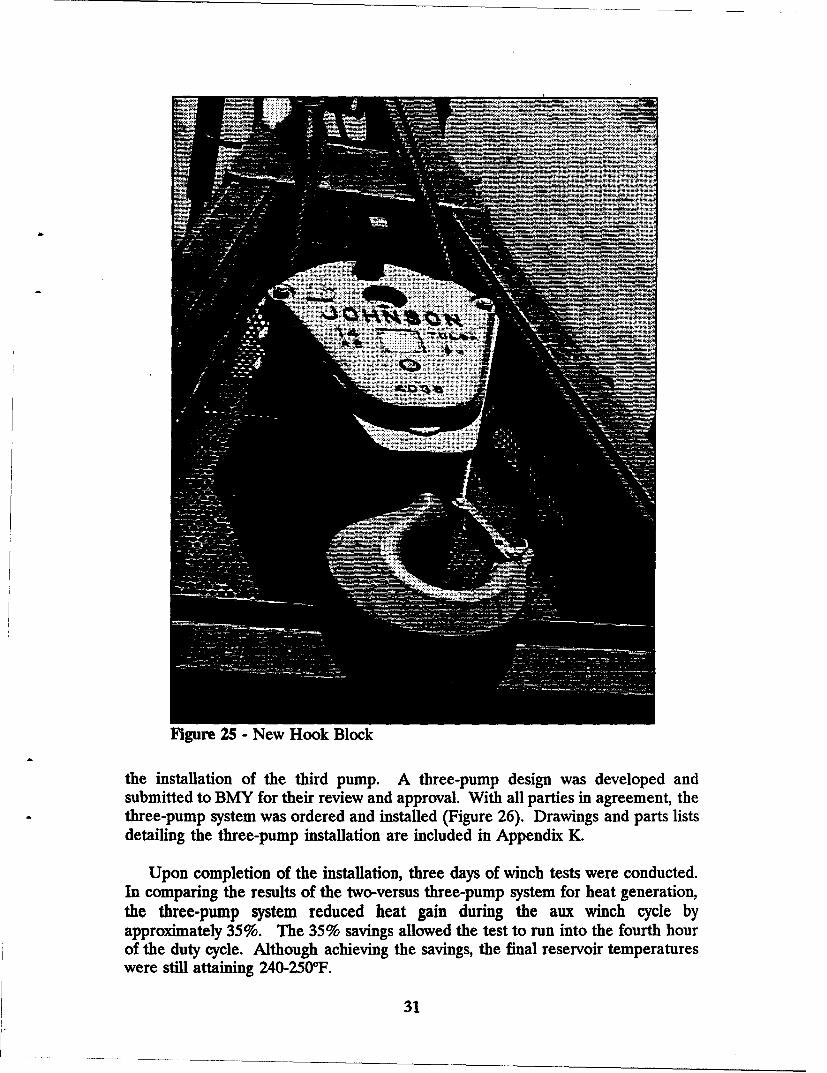
Figure 25- New Hook Block
the installation of the third pump. A three-pump design was developed andsubmitted to BMY for their review and approval. With all parties in agreement, thethree-pump system was ordered and installed (Figure 26). Drawings and parts lists
detailing the three-pump installation are included in Appendix K.
Upon completion of the installation, three days of winch tests were conducted.In comparing the results of the two-versus three-pump system for heat generation,the three-pump system reduced heat gain during the aux winch cycle byapproximately 35%. The 35% savings allowed the test to run into the fourth hourof the duty cycle. Although achieving the savings, the final reservoir temperatureswere still attaining 240-2500F.
31
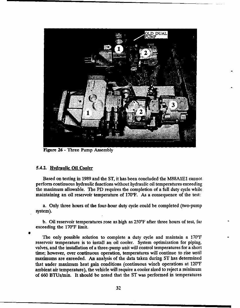
Figure 26 - Three Pump Assembly
5.4.2. Hydraulic Oil Cooler
Based on testing in 1989 and the ST, it has been concluded the M88A1E1 cannotperform continuous hydraulic functions without hydraulic oil temperatures exceedingthe maximum allowable. The PD requires the completion of a full duty cycle whilemaintaining an oil reservoir temperature of 170*F. As a consequence of the test:
a. Only three hours of the four-hour duty cycle could be completed (two-pumpsystem).
b. Oil reservoir temperatures rose as high as 250'F after three hours of test, farexceeding the 170*F limit.
0i
The only possible solution to complete a duty cycle and maintain a 170'Freservoir temperature is to install an oil cooler. System optimization for piping,valves, and the installation of a three-pump unit will control temperatures for a shorttime; however, over continuous operation, temperatures Will continue to rise untilmaximums are exceeded. An analysis of the data taken during ST has determinedthat under maximum heat gain conditions (continuous winch operations at 120'Fambient air temperature), the vehicle will require a cooler sized to reject a minimum
of 660 BtUs/min. It should be noted that the ST was performed in temperatures
32
50-60TF not 1200F temperatures. Appendix L consists of a thermal analysis, sizingdata, and an example cooler selection for the M88A1E1 hydraulic system. Figure27 exhibits a generic fin tube, air to oil, heat exchanger.
Adding an oil cooler to the M88A1E1 will require vehicle modifications. These
modifications include:
a. Ballistic housing for the cooler.
b. Air filtration system for incoming cooler air.
c. Piping and valving interface connections between cooler and hydraulic system.
Upon successfully installing the cooler, a smies of tests should be run to optimizethe cooler selection. Downsizing of the cooler will be a benefit to vehicle packaging.
33
-- --- ' -• -- 7_
Figure 27 - Typical Air-Oil Heat Exchanger
34

"APPENDIX A
Program Personnel
A-1
A-2
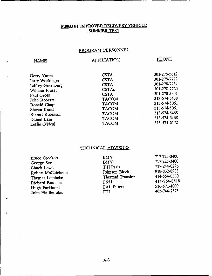
M88A1E1 IMPROVED RECOVERY VEHICLESUMMER TEST
PROGRAM PERSONNEL
NAME AFFILIATION PHONE
Gerry Yursis CSTA 301-278-5612
Jerry Workinger CSTA 301-278-7722
Jeffrey Greenberg CSTA 301-278-7734
William Fraser CSTA& 301-278-7720
Paul Gross CSTA 301-278-3801
John Roberts TACOM 313-574-6438
Ronald Chapp TACOM 313-574-5061
Steven Knott TACOM 313-574-5061
Robert Robinson TACOM 313-574-6468
Daniel Lam TACOM 313-574-6468
Leslie O'Neal TACOM 313-574-6172
TECHNICAL ADVISORS
Bruce Crockett BMY 717-225-3400
George See BMY 717-225-3400
Chuck Lewis T.H.Paris 717-244-0296
Robert McCutcheon Johnson Block 918-832-8933
Thomas Lembcke Thermal Transfer 414-554-8330
Richard Bradach P&H 414-764-8518
Hugh Parkhurst PAL Filters 516-671-4000
John Eleftherakis FTI 465-744-7375
A-3
A-4
APPENDIX B
Major Test Incident Reports
B-1
B-2
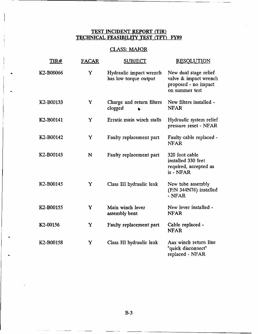
TEST INCIDENT REPORT (TIR)
TECHNICAL FEASIBILITY TEST (TFT) FY89
CLASS: MAJOR
TIR# FACAR SUBJECT RESOLUTION
K2-B00066 Y Hydraulic impact wrench New dual stage reliefhas low torque output valve & impact wrench
proposed - no impacton summer test
K2-B00133 Y Charge and return filters New filters installed -clogged 4. NFAR
K2-B00141 Y Erratic main winch stalls Hydraulic system reliefpressure reset - NFAR
K2-B00142 Y Faulty replacement part Faulty cable replaced -NFAR
K2-B00143 N Faulty replacement part 320 foot cableinstalled 330 feetrequired, accepted asis - NFAR
K2-B00145 Y Class III hydraulic leak New tube assembly(P/N 344N76) installed- NFAR
K2-B00155 Y Main winch lever New lever installed -assembly bent NFAR
K2-00156 Y Faulty replacement part Cable replaced -NFAR
K2-B00158 Y Class III hydraulic leak Aux winch return line"quick disconnect"replaced - NFAR
B-3
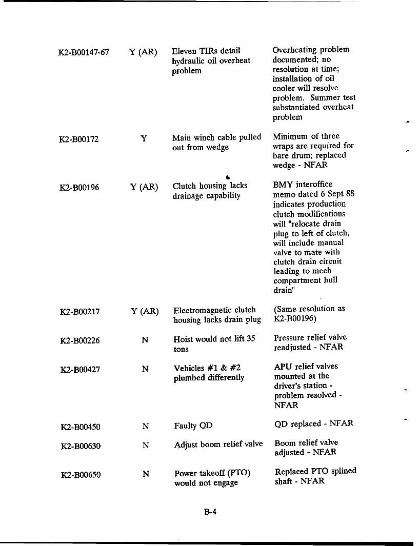
K2-B00147-67 Y (AR) Eleven TIRs detail Overheating problemhydraulic oil overheat documented; noproblem resolution at time;
installation of oilcooler will resolveproblem. Summer testsubstantiated overheatproblem
K2-B00172 Y Main winch cable pulled Minimum of threeout from wedge wraps are required for
bare drum; replacedwedge - NFAR
K2-B00196 Y (AR) Clutch housing lacks BMY interofficedrainage capability memo dated 6 Sept 88
indicates productionclutch modificationswill "relocate drainplug to left of clutch;will include manualvalve to mate withclutch drain circuitleading to mechcompartment hulldrain"
K2-B00217 Y (AR) Electromagnetic clutch (Same resolution ashousing lacks drain plug K2-B00196)
K2-B00226 N Hoist would not lift 35 Pressure relief valvetons readjusted - NFAR
K2-B00427 N Vehicles #1 & #2 APU relief valvesplumbed differently mounted at the
driver's station -problem resolved -NFAR
K2-B00450 N Faulty QD QD replaced - NFAR
K2-B00630 N Adjust boom relief valve Boom relief valveadjusted - NFAR
K2-B00650 N Power takeoff (PTO) Replaced PTO splinedwould not engage shaft - NFAR
B-4

K2-B00678 N Noise coming from PTO New PTO clutchassembly required, PTO
replaced - NFAR
K2-B00778 N PTO clutch would not PTO replaced - sameengage as K2-B00678
K2-C000008 N Aux cable wrap problem New modified auxwinch installed -NFAR
K2-CO00010 N Class III leak - main New cap plug installedwinch - NFAR
K2-CO00011 N Main winch cable Replaced cable -damaged NFAR
K2-C000016 N Level wind damaged Sheared mounting boltreplaced - level windfailure problem solvedduring summer test
K2-C000038 N Faulty filter valve Faulty filter valvemanifold manifold replaced -
NFAR
K2-C000040 N Erratic main winch Load sense linebehavior relocated during
summer test, erraticbehavior eliminated -NFAR
K2-C000041 N (AR) Aux boom inadequate Not addressed duringsummer test - BMY toaddress under contracttwo modifications
K2-C000042 N Hoist sheave seized up New hoist sheavedesign to be installedby BMY undercontract two
B-5
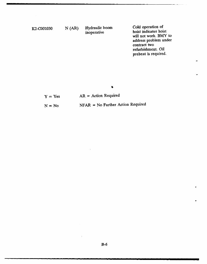
K2-C001030 N (AR) Hydraulic boom Cold operation of
inoperative hoist indicates hoistwill not work. BMY toaddress problem undercontract tworefurbishment. Oilpreheat is required.
Y = Yes AR = Action Required
N = No NFAR = No Further Action Required
B-6
APPENDIX C
1990 Summer Test Directive
c-1
C-2
M88A1E1 HYDRAULICS TEST DIRECTIVE
1. Authority: This test directive provides authority to the Aberdeen ProvingGrounds (APG) to perform the testing contained herein on the M88A1E1hydraulics systems.
2. Test Responsibility: M88A1E1 testing shall be conducted under the direction ofthe Systems Planning Branch (AMSTA-ZDS), TACOM, Autovon 786-5061. Anyrequests or directions received by the test site from any other office or agency shallnot be honored unless specifically authorized by AMSTA-ZDS.
3. M88A1E1 Test Vehicle: Presently five (.) M88A1E1 prototypes are availableat APG for testing. Vehicle #4 shall be used for the hydraulic tests. Vehicle #5shall be available as needed.
4. Purpose of Test: As a result of PreProduction Tests (PPT), it has beendetermined that the M88A1E1 has experienced hydraulic overheat problems. Alsoan excessive buildup of pressure in system pressure relief valves has causedmalfunctions. Both problems appear to be the source of related hydraulic problems.The purpose of this test is to:
a. Identify current M88 hydraulic problems.
b. Determine the source of the problems.
c. Recommend possible corrective actions.
5. Governing Documents: All testing shall be conducted in accordance with thistest directive.
6. Reports and Correspondence: All reports and correspondence issued as a resultof this directive and testing shall include, as reference, test title, TACOM ProjectNumber, and name of system tested.
7. Test Completion: The test should be completed by 31 Aug 90. All tests shallbe scheduled to assure completion within the time requirement. The final testreport shall be submitted within 30 working days of test completion.
8. Test Program Review:
a. An initial meeting was held between APG and TACOM, 16-17 Apr 90,to discuss the results of the PPT and to try and determine what M88A1E1operational problems still exist.
b. TACOM has reviewed Test Incidence Reports (TIRs) to determine what
C-3
actual problems were reported during PPT. Based on' the TIR review andconversations held at APG, basic hydraulic problems have been identified. TACOMhas written this test plan to determine if these problems still exist, and if they do,what steps might be taken to correct the problems.
C. If deemed necessary by the sponsoring activity (TACOM,AMSTA-Z-IRV), a test review meeting shall be called at a location to bedetermined. The conference may include, but is not limited to the discussion of thefollowing items:
(1) Test delays and their causes.
(2) Deviations from the test directive.
(3) Discrepancies discovered during testing that APG or TACOMdetermine to be of major concern.
(4) Miscellaneous items of significance.
9. Spare Part Support: CSTA shall supply all necessary spare parts as available tokeep tests running on schedule. Spare parts shall include but not be limited tohydraulic oil, quick disconnect fittings, pressure hose, valving and actuators.
10. Test Procedure:
a. System Verification: The system developer, BMY, shall supply systeminstallation drawings and/or available manuals for all hydraulic circuits. A TACOMhydraulics technician shall use the installation drawings to verify the actual hydrauliccircuitry plumbed into vehicle #4. Any discrepancies shall be marked on thedrawings. A TACOM hydraulics technician shall be on site to assist in the systemverification prior to testing.
b. System Inspection: Each hydraulic system shall be further inspected toinsure its' integrity. All hoses shall be connected, systems shall be full of oil, andall moving parts (motors, pumps, actuators, etc.) shall be operable.
c. Test Reporting: All serious test incidents shall be immediately reportedto AMSTA-ZDS by telephone (AV 1-786-5061). CSTA shall submit raw test datadirectly to TACOM, AMSTA-ZDS. A cover letter shall be attached brieflydescribing the data being submitted. Data shall be issued in accordance withdistribution instructions contained in paragraph 13.
d. Performance Phase:
(1) A series of operational tests shall be performed to:
(a) Verify if defects found during PPT have been corrected or
C-4
still exist.
(b) Determine the cause of current hydraulic problems.
(c) Determine if other major problems exist that may not havebeen uncovered during the PPT.
(2) The following hydraulic circuits shall be identified and tested:
(a) pump/filter main charging loop
(b) hoist/winch
(c) main/auxiliary wincl4
(d) boom
(e) spade
(f) stayline
(3) Parameters to be monitored during circuit testing are:
(a) reservoir temperature
(b) flow rate immediately after the main pump
(c) pressure and temperature exiting main pump
(d) for each circuit containing actuators, pressure andtemperature exiting one (1) of the actuators.
(e) for each circuit containing a pressure relief valve, pressureand temperature immediately downstream of the valve.
(f) pressure immediately upstream of the valve, to allow forpressure drop determination.
(4) The raw test information gathered shall conform to the formatgiven in exhibit #1. The top third of the page shall contain a sketch of the circuitbeing tested. The sketch shall describe all elements of the circuit to include; pumps,motor, actuators, valving, reservoir, test gauge locations, and hose sizing. The lowertwo thirds of the page shall list the test results in the format of exhibit #1.
(5) Vehicle #4 shall be tested at conditions that produce maximumwork or heat for the purpose of verifying the operational capabilities of thehydraulic system. The following operational conditions shall be tested:
C-5
(a) Engine Speed: For each series of tests, the engine shall betested at tactical idle or 1800 RPMs. An idle or full RPM condition shall have aminimum duration of 30 minutes. During this 30 minute interval, temperatures,pressures, and flows shall be monitored. If there are no appreciable changes invalues being recorded, +5%, the test data may be considered acceptable. Ifpressure values increase more than 5% over full rpm conditions, the test shall becontinually monitored. If the pressure increases 10% or more, the test shall behalted. With the use of 15 W 40 wt. hydraulic oil, the maximum allowable systemtemperature shall be 170 degrees Fahrenheit. Tests shall be halted above thistemperature.
(b) Boom Operation: The boom shall be tested under no andfull load conditions. Full load shall be 35 tons in accordance with vehiclespecifications. In the raising and lowering .of the boom, the boom shall beintermittently stopped and started. It is necessary to check the ability of the boomto be restarted from an intermediate point of travel.
(c) Main/Aux Winch: Payout of the main winch shall bethrough the use of the aux winch. For the main winch payin, the cables' deadweight shall be sufficient loading for the retrieval. Time of retrieval shall berecorded. For the aux winch, the shackles on the vehicle shall be used to load thecable during the retrieval. The cable dead weight pull shall be the no-load case.The full load main winch test shall be a 140,000 lb. static pull. The static pull shallbe made against a static anchor until the winch stalls. At which point a load cellshall measure the pulling capacity. CSTA shall use three to four vehicles or theirlarge Dynamometer as the anchor. The M88A1E1 has been designed for static, notdynamic testing. The static pull test shall be completed for 1, 2, and 3 layers ofcable wrapped around the winch drum.
(d) Test Repetitions/Measurements: A minimum of three (3)repetitions of each test shall be made. Pressure, temperature, and flow recordingsshall be made at five minute intervals. Should pressure readings exceed 5% ofnormal operating conditions, raw data recordings shall be made every minute.
(6) APG shall have the following test equipment available:
(a) Hydraulic test stand for the measuring and monitoring oftemperatures and pressures.
(b) Five (5) each pressure transducers. They shall have digitalreadouts. The pressure transducers shall monitor pressures up to 5000 psi.
(c) Five (5) each fast response temperature sensors with digitalread outs.
(d) A digital storage oscilloscope that is capable of monitoringthe output of the pressure transducers.
C-6
(e) A strip chart readout for the temperature sensors. It shall
have a minimum two (2) input channels, preferably five (5) if available.
(f) An x-y plotter to interface with the oscilloscope.
(g) 70,000 pounds of dead weight to be used during boomtesting. A load cell that can read 70,000 lbs. shall be provided. Measurementinstrumentation shall be included.
(h) CSTA's large dynamometer is required for the 140,000 lb.winch test. A load cell reading to 140,000 lb. is required. if the dynamometer is notavailable, alternate solutions would be two M60A3s and one M88A1 or two M88swith the plow blades down to simulate the same loading. The load cell shall includemeasurement instrumentation.
11. Test Scope:
a. Summary of Test Objectives:
(1) Determine to the best extent possible what hydraulic problems,if any, still exist in the five M88A1E1 prototype vehicles at APG. The testing willcenter on problems determined during PPT and documented in the cover letter orthe TIRs.
(2) Become knowledgeable of the current systems installed in theM88A1E1. Accurate system installation drawings are not available as of 11 Jun 90.
(3) Determine any hydraulic problems that were not addressed in theTIRs. It is important to determine what these problems might be. Any additionalproblems found during the operational tests shall be documented for furtherevaluation and resolution.
(4) Determine solutions to hydraulic problems wherever possible.
b. Test Schedule: Operational testing of vehicle #4 at APG is scheduled tostart the 9th of July and be completed by the 30 Aug 90.
12. Final Inspection: Upon completion of all testing, the vehicles tested shall beinspected to determine the condition of each vehicle and returned to Bldg. 420 forpreparation for shipment.
13. Reporting:
a. Upon completion of the tests, TACOM, AMSTA-ZDS, shall prepare adetailed report describing the systems tested, test results, and any recommendationsresulting from tests performed.
C-7
b. All pertinent information, major test incidents and/or failures, shall beimmediately reported and confirmed by telephone to AMSTA-Z-IRV, phone #1-313-574-8832.
c. All testing results, TIRs and final test report shall be distributed only tothe organization specifically listed below:
CommanderU.S. Army Tank-Automotive CommandAMSTA-Z-IRVWarren, Mich 48397-5000Attn: Mr. Ron Chapp
C-8
APPENDIX D
Hydraulic System Diagram
D-1
D-2
Alm
___ I
S ~ ~ ~ ~ ~ LL
- - - - -- - ---. - - - i -q - - - * . ..
.1RALI teEAo I

S
*1
- ' -i - - - - - - ------ ---~-3 -- - - - - -- - - - - - - - --- - - - - - - -- - - - ----
JX -------, ------------------------------
--- ----------- --- -- - --------------
________________ .1 --- h--p- .
iIt
s' It'
. ...... . ....-
-i -- -- -- - -
J6 *
-- ------ --------- -----------------------.-- - - - -
-tfn - tlt
- --- - - - - - - - - - - - -
4e e - - - - - - - - - - -- - - - - - - - - -
-- - --'.
- --------
eN *--.-*------------------------------
P-b .
L * -- --------~
L4...f.. -
-h ow.~II
b
b

"APPENDIX E
Test Instrumentation
E-1
E-2
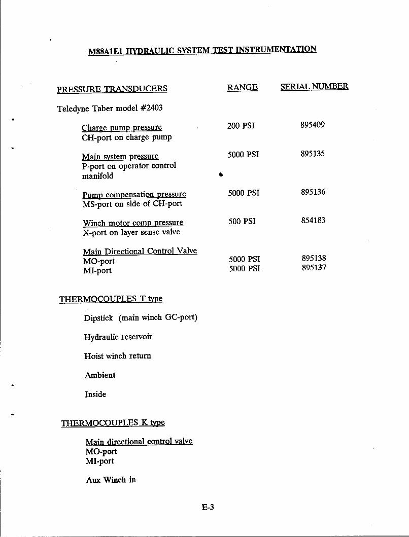
M88A1E1 HYDRAULIC SYSTEM TEST INSTRUMENTATION
PRESSURE TRANSDUCERS RANGE SERIAL NUMBER
Teledyne Taber model #2403
Charge pump pressure 200 PSI 895409
CH-port on charge pump
Main system pressure 5000 PSI 895135
P-port on operator controlmanifold
Pump compensation pressure 5000 PSI 895136MS-port on side of CH-port
Winch motor comp pressure 500 PSI 854183X-port on layer sense valve
Main Directional Control ValveMO-port 5000 PSI 895138
MI-port 5000 PSI 895137
THERMOCOUPLES T type
Dipstick (main winch GC-port)
Hydraulic reservoir
Hoist winch return
Ambient
Inside
THERMOCOUPLES K type
Main directional control valveMO-portMI-port
Aux Winch in
E-3
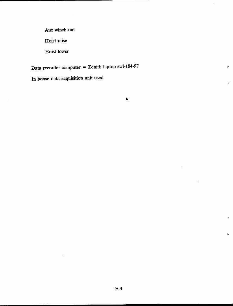
Aux winch out
Hoist raise
Hoist lower
Data recorder computer = Zenith laptop zwl-184- 97
In house data acquisition unit used
E-4
- - - - - - - - - - - - - - - -
-T ------
FLUTtE2 VALVE
PR IEI I
pp~sURE L -A.-_
B 7
P I T I I i I
PT INI
MAINI
1I 12364851
1~AI UT
L-J
TOIS
IT IIC
VALV PSI L-~
r RELEASED -
~ -~COUNTErBALAVCE
E-5
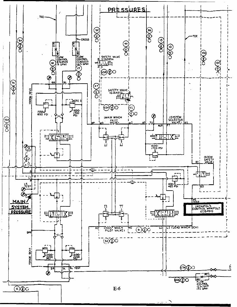
PRi s U rtFp- s
,% COS I
p~ 46
r C I10I
F L LO :i SFT AV
-O O CONRO 6! 123485
N1E3
Rr NOTE 3 C
1700
lap~~~ ~ ~ ~ ~ 'M IV TA At
AUX T
_ 1TI__ I'__1 700
ýESI
[j~PSI 00M
r C~ROLSANFTY
BTE, AAI0
TI tOSWrCI 30L LAw~~OV
I ILTvAV)
*7F
Ls 4 --TESTCONTR so
DU~~ La~EO7p PU
PRESSURES
- -
M"- ip O "" '
I I.-I mI -
I I- -
' I LI IISPADE CYLINDER
, .pg
(IO867173) LEVEL WINDER
ro 5 9 60 LEVEL WINDERCONTtOL VALVE - 6 61
123643e4
, I
_ ____
_ _,_ _H,
!PHI
__ M ~ N ~123,f
WINCH M _ -ýoa
COME 'RSSUR- z LAEy-R SENSE 9AVALVE'
400 psi
IT .. --. CRA
I _____ __._55
1 | • RELIE. VALVEL RUL
MIN.-,. ,PLCEMENC I4 I , I.'.
.I I
~~~~PLAL MVALVE-
I i-' f -- -
,,--- -- --
Ii INHAuL
_E-7
,i FIEE
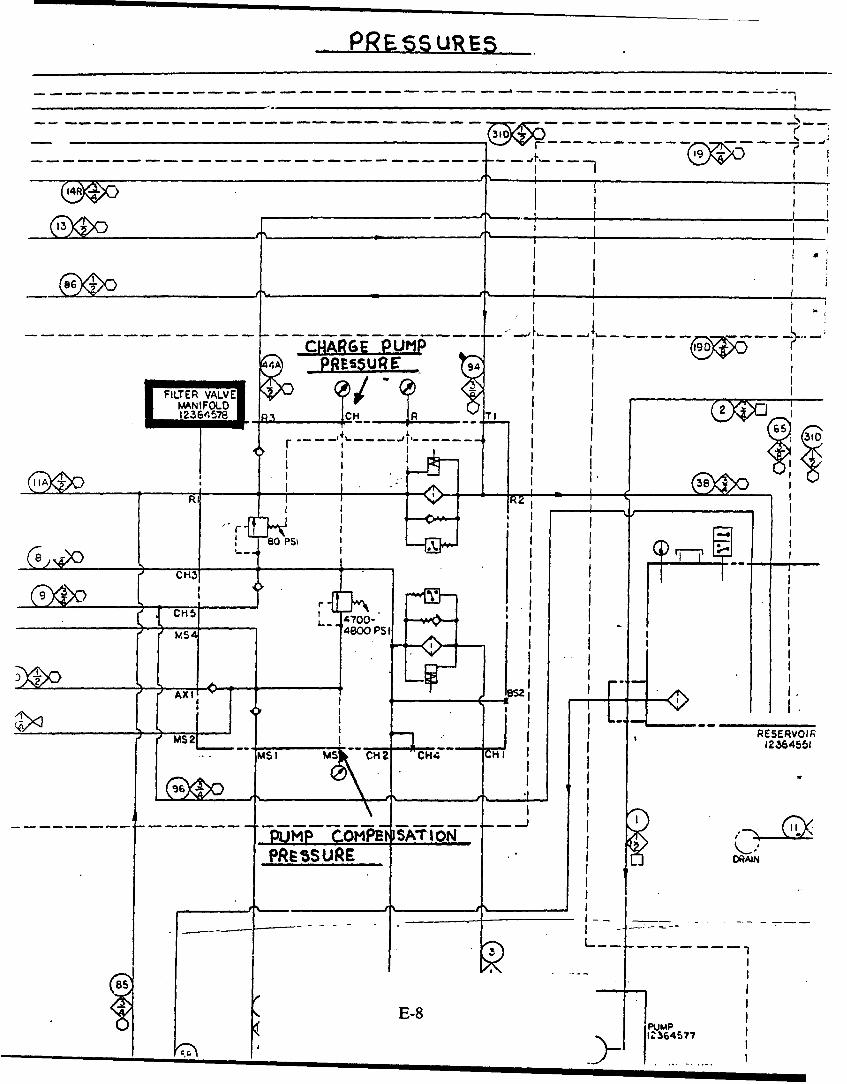
PRESs URES
3101
- ----------- --- 4 - -
C1A - P UI
I I i___I L
r- -- -_ -L___ --
S..... . _J v./ 4-4, A -= ...... 4 I I
r IIMAN ,FLI I
....... CHA U R C- I
pI IsREI I
IA. . . u . . 1 38 _
1 I
II I
I 8PS
CH'
___ ___ ___ _________L~ 4700-
S.S4 4800PSI
AXI
,,i I .,
s 2,I RESERVOIR
MSI H2 CH"1 I 12364551
PUMP COMPE SATIONPRESSURE DRAIN
E-8 P
I I I I II2I6I5I7
I r
--------------------
" 'r--- .---•-'-r-:;.I i0. ..
SP*ODE CYLINDER Ii .
Je67173 LEVEL WINDER, - ,
Ii I
1236 1 q
LEVEL VANDER 6CC)NTSOL VALVE -
12364384 A L
f ,H, --I rnPn
L A L fifl
CRACIKINC-"" "r .. MAmiF:oLD ldi,'..4943 "550 PS
RELIEFr IILVE RELEASED
L I
I " --- __- - '-"-
MIN. _ .P.AC_ M.T I-+ -0
0i g)0
SI INTL -L ,NA
o_, __ E-__ _ __
E-1O

APPENDIX F
Summer Test Chronology
F-1
F-2
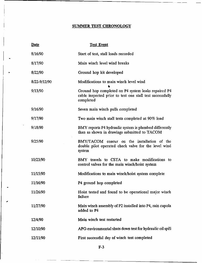
SUMMER TEST CHRONOLOGY
Date Test Event
8/16/90 Start of test, stall loads recorded
8/17/90 Main winch level wind breaks
8/22/90 Ground hop kit developed
8/22-9/12/90 Modifications to main winch level wind
9/13/90 Ground hop completed on P4 system leaks repaired P4cable inspected prior to test one stall test successfullycompleted
9/16/90 Seven main winch pulls completed
9/17/90 Two main winch stall tests completed at 90% load
9/18/90 BMY reports P4 hydraulic system is plumbed differentlythan as shown in drawings submitted to TACOM
9/25/90 BMY/TACOM concur on the installation of thedouble pilot operated check valve for the level windsystem
10/23/90 BMY travels to CSTA to make modifications tocontrol valves for the main winch/hoist system
11/15/90 Modifications to main winch/hoist system complete
11/16/90 P4 ground hop completed
11/26/90 Hoist tested and found to be operational major winchfailure
11/27/90 Main winch assembly of P2 installed into P4, rain cupolaadded to P4
12/4/90 Main winch test restarted
12/10/90 APG environmental shuts down test for hydraulic oil spill
12/11/90 First successful day of winch test completed
F-3
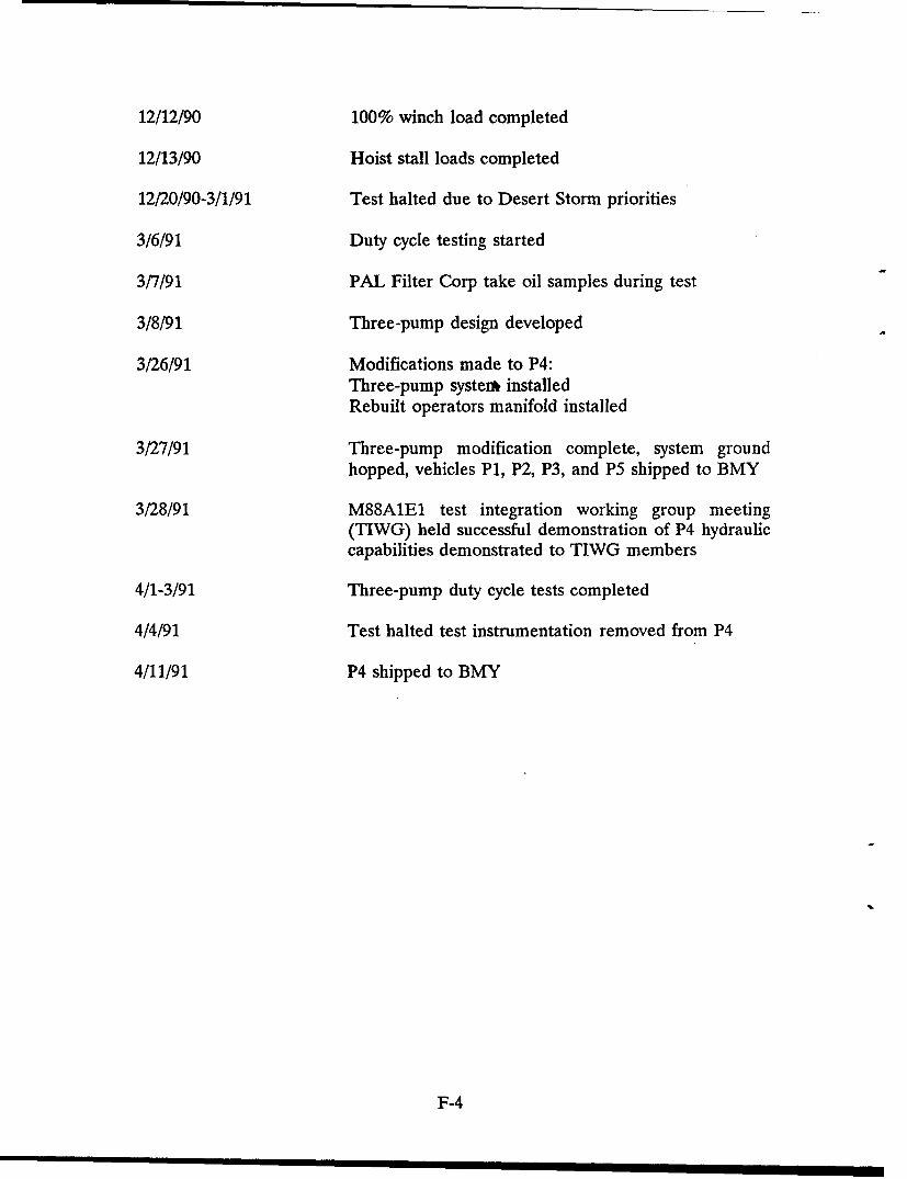
12/12/90 100% winch load completed
12/13/90 Hoist stall loads completed
12/20/90-3/1/91 Test halted due to Desert Storm priorities
3/6/91 Duty cycle testing started
3/7/91 PAL Filter Corp take oil samples during test
3/8/91 Three-pump design developed
3/26/91 Modifications made to P4:Three-pump system• installedRebuilt operators manifold installed
3/27/91 Three-pump modification complete, system groundhopped, vehicles P1, P2, P3, and P5 shipped to BMY
3/28/91 M88A1E1 test integration working group meeting(TIWG) held successful demonstration of P4 hydrauliccapabilities demonstrated to TIWG members
4/1-3/91 Three-pump duty cycle tests completed
4/4/91 Test halted test instrumentation removed from P4
4/11/91 P4 shipped to BMY
F-4
APPENDIX G
Summer Test Incidents
G-1
G-2
SUMMER TEST INCIDENTS
DATE INCIDENT(I)IRESOLUTION(R)
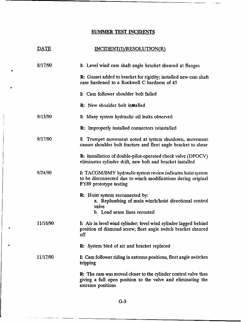
8/17/90 I: Level wind cam shaft angle bracket sheared at flanges
R: Gusset added to bracket for rigidity; installed new cam shaft
case hardened to a Rockwell C hardness of 45
I: Cam follower shoulder bolt failed
R: New shoulder bolt intalled
9/13/90 I: Many system hydraulic oil leaks observed
R: Improperly installed connectors reinstalled
9/17/90 I: Trumpet movement noted at system shutdown, movementcauses shoulder bolt fracture and fleet angle bracket to shear
R: Installation of double-pilot-operated check valve (DPOCV)eliminates cylinder drift, new bolt and bracket installed
9/24/90 I: TACOM/BMY hydraulic system review indicates hoist systemto be disconnected due to winch modifications during originalFY89 prototype testing
R: Hoist system reconnected by:a. Replumbing of main winch/hoist directional controlvalveb. Load sense lines rerouted
11/16/90 I: Air in level wind cylinder; level wind cylinder lagged behindposition of diamond screw; fleet angle switch bracket shearedoff
R: System bled of air and bracket replaced
11/17/90 I: Cam follower riding in extreme positions, fleet angle switchestripping
R: The cam was moved closer to the cylinder control valve thusgiving a full open position to the valve and eliminating theextreme positions
G-3
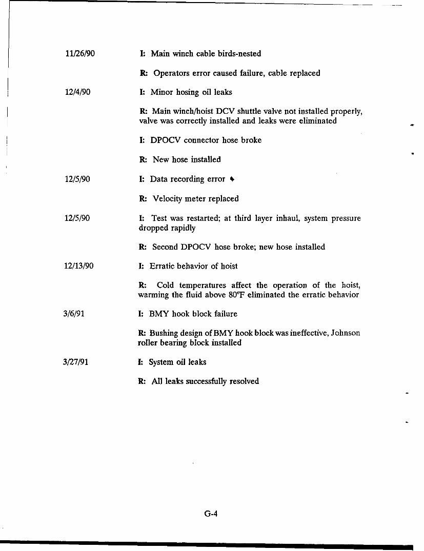
11/26/90 I: Main winch cable birds-nested
R: Operators error caused failure, cable replaced
12/4/90 I: Minor hosing oil leaks
R: Main winch/hoist DCV shuttle valve not installed properly,valve was correctly installed and leaks were eliminated
I: DPOCV connector hose broke
R: New hose installed
12/5/90 I: Data recording error 1
R: Velocity meter replaced
12/5/90 I: Test was restarted; at third layer inhaul, system pressuredropped rapidly
R: Second DPOCV hose broke; new hose installed
12/13/90 I: Erratic behavior of hoist
R: Cold temperatures affect the operation of the hoist,warming the fluid above 80'F eliminated the erratic behavior
3/6/91 I: BMY hook block failure
R: Bushing design of BMY hook block was ineffective, Johnsonroller bearing block installed
3/27/91 I: System oil leaks
R: All leaks successfully resolved
G-4

"APPENDIX H
Test Data
H-1
H-2
Test Data
Data for the M88A1E1 hydraulic summer test was gathered over the period 16 Aug90 to 2 Apr 91 by the CSTA test personnel. Eighty-one (81) total test runs weremade. The data was collected in the following sequence:
a. Stall data
b. Baseline winching (Runs 1-53):
1.) 50% (70,0001b. load) winch inhaul
2.) 75% (105,0001b. load) winch inhaul
3.) 90% (126,0001b. load) winch inhaul
4.) 100% (140,0001b. load) winch inhaul
5.) 110% (154,0001b. load) winch inhaul
c. Baseline hoisting (Runs 54-63)
d. Duty Cycle test, two-pump system (Runs 64-71)
e. Duty Cycle test, three-pump system (Runs 72-81)
All test data gathered is given in Tables 1 - 3.
Test runs 1-63 covered baseline test data. The operation of the vehicle was beingtested during these runs. Test runs 64-81 represent duty cycle testing. In Section5 of this report modifications were made to the hydraulic system. Thesemodifications are included in Runs 64-81. Also in Section 5, reference is made tothe installation of a three-pump system. This three-pump system was installed fortest runs 72-81.
For each test run made, the raw test data was taken by CSTA and plotted in graphform by computer. Temperatures and pressures were plotted versus time for eachtest run. A composite graph for temperatures and pressures was also given for eachrun. The following graphs were plotted:
a. Temperatures vs. Time for:
1.) Main winch
2.) Hydraulic reservoir
3.) Hoist winch
H-3
4.) Ambient
5.) Inside (crew compartment)
6.) Main out (winch)
7.) Main in (winch)
8.) Aux in (at aux winch)
9.) Aux out (at aux winch)
10.) Hoist raise
11.) Hoist lower
b. Pressure vs. Time for:
1.) Main system
2.) Main in
3.) Pump compensation
4.) Main out
5.) Charge pump
6.) Winch motor comp
Volumes of graph data were plotted for the 81 runs. Graph data for runs 1-63represent data for the nonmodified system and are not pertinent to this report. Forthis reason, the graph data is not included in this report. Runs 64-71 represent datafor the two pump modified system. The graph data for one run was typical of thedata for the other seven runs and, therefore, the data for only one run, number 71,is presented. In a like manner, run 81 was included to represent the three-pumpmodified system. Runs 71 and 81 have been chosen as a comparison to exhibit thedifferences in pressures and temperatures between the two-pump and three-pumpsystems. The benefit gained by installing the three pump-system was determined bythis comparison to be a 30% reduction in hydraulic oil heat gain.
Figure 1 is presented as reference in describing the pressure fluctuations for atypical duty cycle. The pressure spikes are labeled to describe the cycle operation.The duty cycle followed the following sequence of events:
a. spade down
H-4
b. boom up
c. hook block lowered
d. first hoist
e. hoist lower
f. second hoist
g. hoist lower
h. third hoist
i. hoist lower
j. boom up
k. spade up
1. aux out
m. aux pull
n. aux in
o. first layer 140,000 lb. main winch pull
p. second layer main winch pull
r. third layer main winch pull
s. spade up
t. charge pump (idle pressure)
Figure 2 depicts the break down of the duty cycle into the lift, aux winch, and mainwinch cycles.
4
H1-5
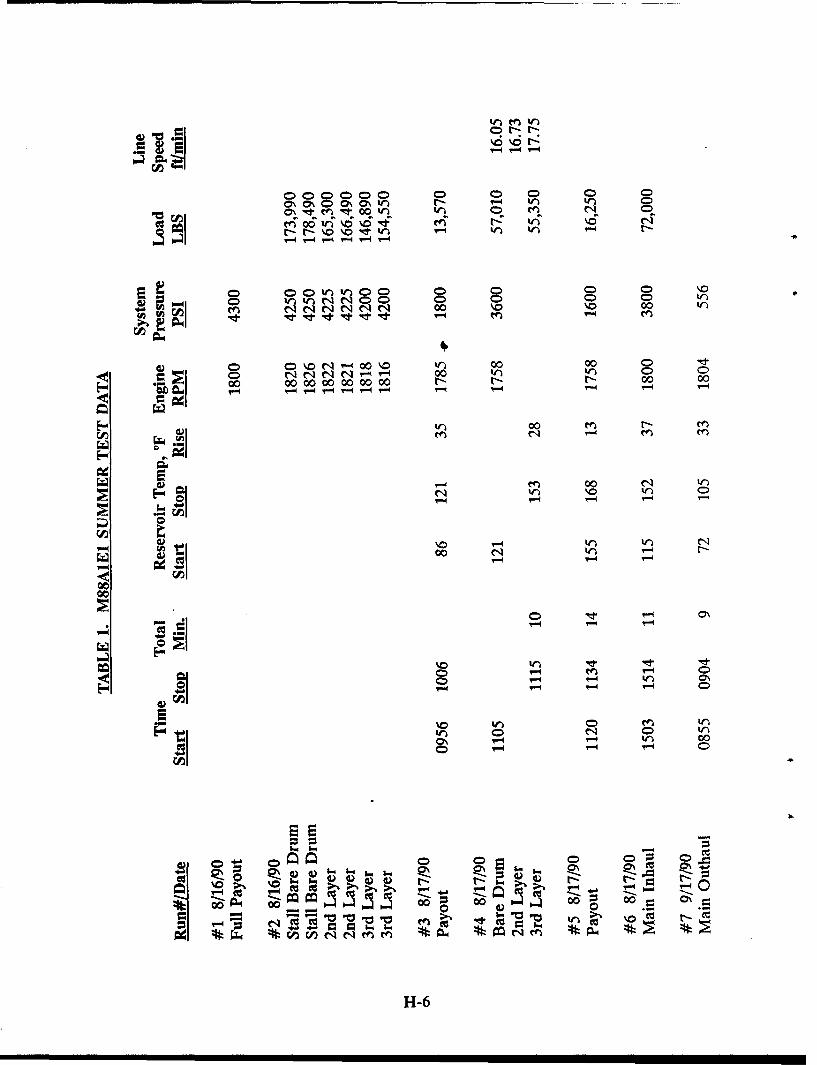
0 00 0 0\ 0) 0\ 0\ 0) r W ) C000\ \% ) Nt m tr 0 t trn 0 n cq
ed~~~ ceý 06lý\6% Rý% l
r-- r- \0 00 0i 0 0
MI Qt tN CDO 0 0 0 0D tN qN N 00 \0 \.0 00
0 %0 .N 00 \0 wl 00 00 0 "IQ0 C N C4N '-q r-. 00 V 0 000 00 0000 0000 00 N- N N 00 00
00 N- e
en 00 N iNn \0 0D
00 Nq r-
00
0- - 0%-~r- '-0- -
00 ;6 40 0 0 0\ren0 w "a E0%>%t-;-q - - -
0n V)eqqene
H-6N
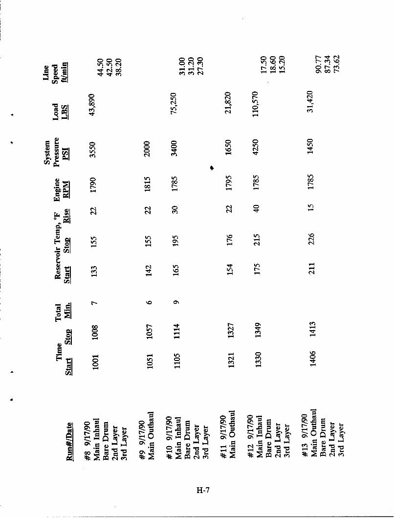
0 q00 000 000 w; C;t- v
N N N000N 0
0N 0 00 0 0 00
00 r- 00 t- -4
C) C
00
N> ') It)
C4 N- e
N '.
0 -4-0 C1 -j 'r. c-
I(q - 0-A cn0
0-
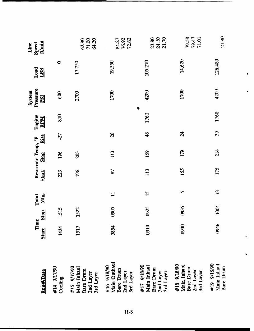
000 M-N 000) C 00N t-"4CJ\ C) ~ -N NNftC
00 0- 0 ý 0 00
CD C)000
0 0 0 0)
000
al
0 000
'00
E-4 t W
'0 0
N0 0000'-N0 Q - -
0 00 0
H-84
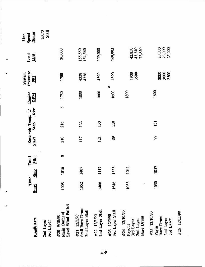
0 C 00 0 000 000a
00 0 0 ) C )C 000)
0) 0ý 0 0 0 0)00 0 0 0 0 r
r- 00 00 00 00 00
'-4 '-4
00-
CAIl
00
00 0 0C
0 W 0 'C4
.~f. 0A ;0D
-1) w0 )C
H-9
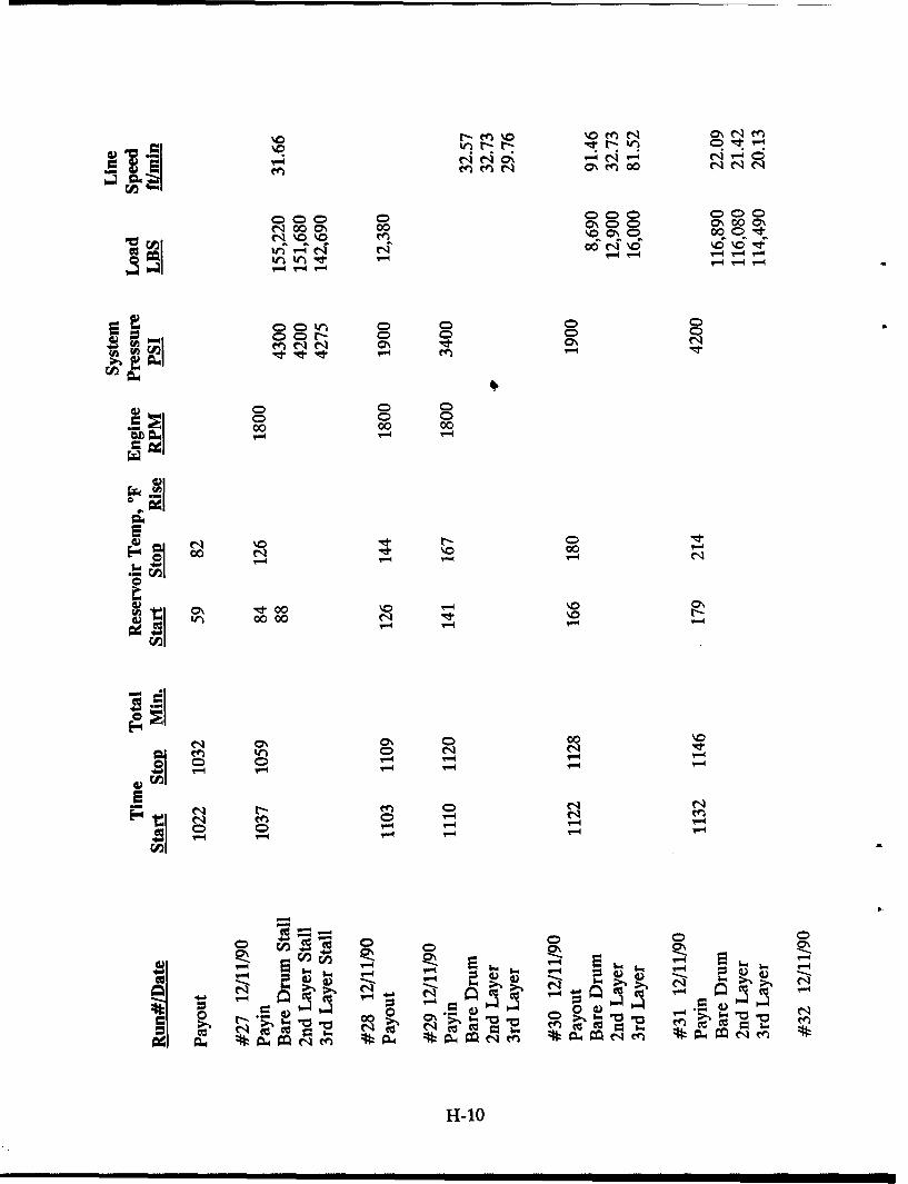
000 0n 000 00
Q CD D C) CD0 C) C C
00V 0 00 07 0 ) 0)C 0Ooor- % n%0 0% C 00 )qd
0D 0 0ý00 00
1-t 00
00 00
V-0 ".4
cq ON ~ 000
0nC - N le
0"
4p r
2.C-- 0 CD
0D "0~iC>
's '".
- ~ C >4 ~
Ne coý ..
H1-10
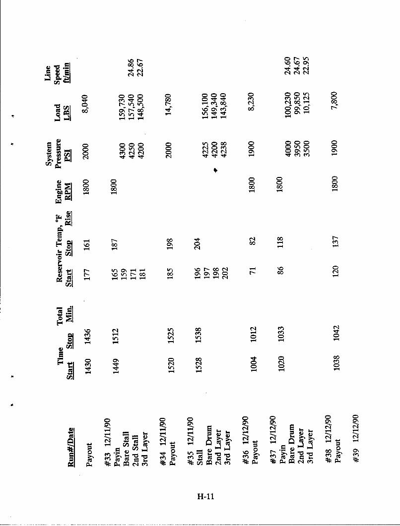
C) --00' \0 oýo Ch
0W 00 00 000 0T 00t/ 0)ePC Q00- - n0 00 ~r-4 00
Cc 06 C-ý rz e0 C\ M0'Cin W "ItV00 'tro "e' Q O -
2 0 00 0 0 C) 0oo 0 000 0 C ) C
CA 9
0D 0) 0 00 0D 000 00 00
00 0N 0o r-4
0- 00000
00r00 0\C0 -
1 C- %0 tn r- 00 00 o\ C C C-) - 00N
N) 00 N NNq en
trW0 0
0 00
0) 0 0C00D 0
- -J,. '.4
N m N N'1N- ~ - - 00
H-il
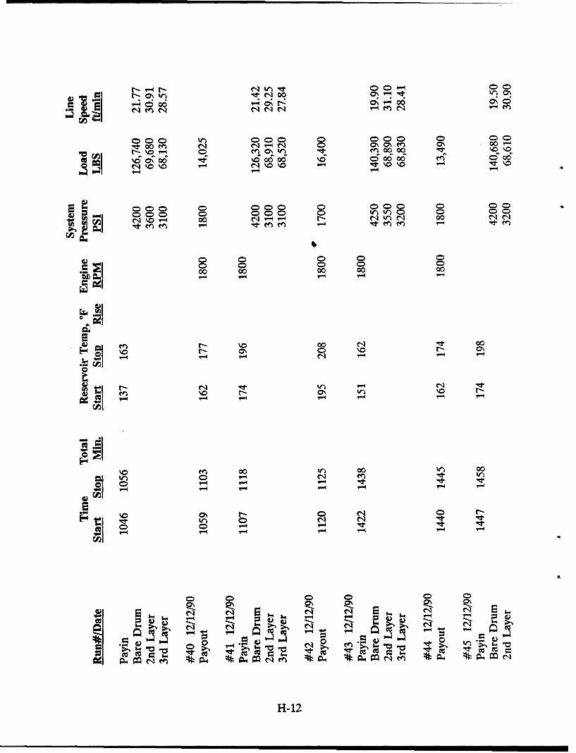
t-~~0~ 00W qtN00n
000C 000) 0 000 0) 00c00 0 qC n 0 00
lod \6 6 06 6 cooo e0
No \ 00 0 >
0 0) 0 0)C )C C >0 0 )C
0 0 0C000 00 00 00 00
r-4
0000 00'-4 - -- 4
-L-
2j
C -. r-4 - ~UV-4
0500)00C) 0'.
CD. CD C C)C
H-12
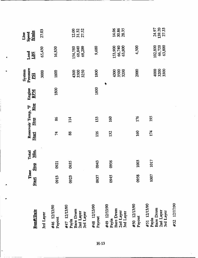
0 0 000 0- 000 0m0
Q2>QC 0 00 0 00 0 000 C C
le 00W 00U C4 10 0-00 0 0 0-00
CO o lfc 406 0r-q r-
0D 0 D0Q0C) QCW~ ~ 0D C )0C ý0C )C
C) C
'0 0 D
I,) 0 000
C- 00 -- en 0 O
r- 0 -4 en \
0
C? Q ~ 000C
00 00 0\ 0 0D0'. 0 0% 0 0'. '. e
H-13
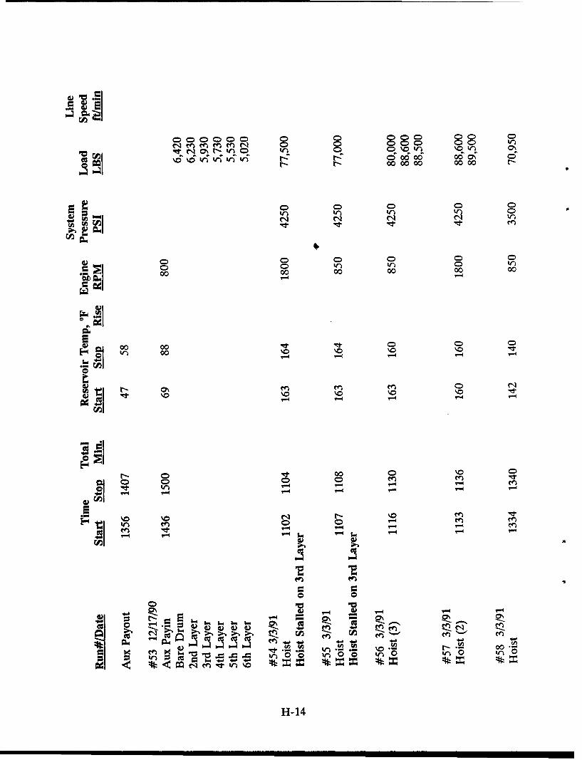
C>~ 0) 000 00)0 C D(D C ) C~N o\ '~ 0ne f )C 0'O ) Q QC)C) wl
Ný 000000 0000 Ný
0- 000 0 00 00 r
I)W 0CD00
00 00 00 00 00
fw 00 00 C
.seg 00 0000 )00r4 .
0 CA
0 o0 N N en> ,> - en en
W) 0 0
C- en -d W) \
H- 14
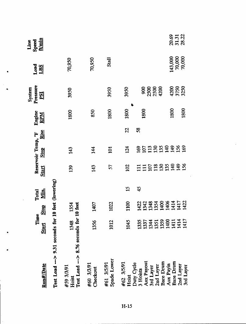
C> 000 C
0 -- 004
0 0) 0 0000C C 000 C
0 0 0 0 0) 0 00 0 000 00
Ni 00
efw~ W) \%0 ~ \ 0%
0% C> Ni - 00 02eC00O %\0r-C*00 Q t- ) Cr4P4C
00~~~~ W) W -q"v.q0 - er
o T- PC V-4 " -4 '- '- '. "-I r-
00~ 0 c f
A A
~-4 0
W~E 4Q 0 - z c
H-15
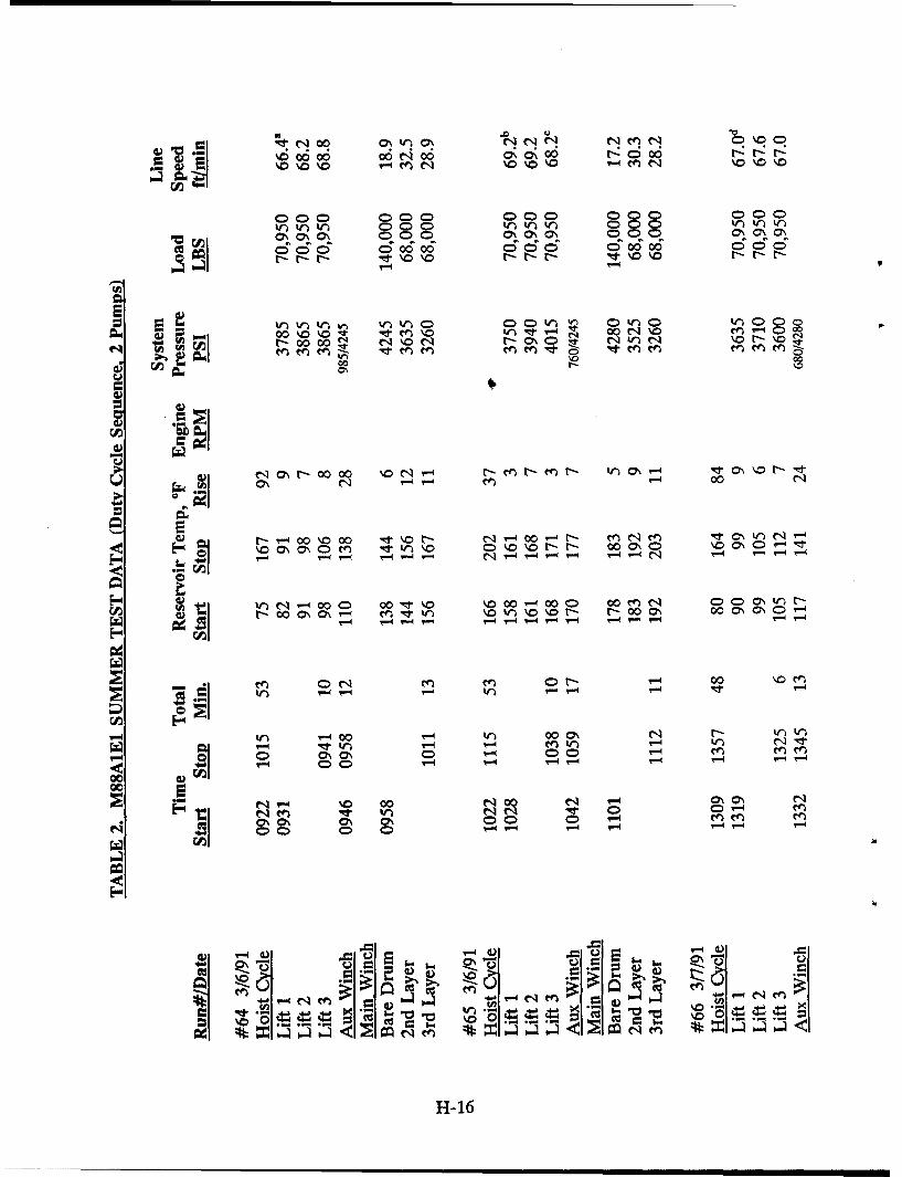
4t(q000 cO\c W) ~ 0 ON0
000 0000 n
00 0 0000 :)C) ( 000 ) )C 00000 00
2pp D CDirIrv- lIC;~ 00 O6 'V00 (D CD
C> 0 nkn C c
0. 4 00 '
NO~~.r0000 O~ ~-
0' -4 00N
tl 0% 0 t - N T- 00 -4 t- - '-4 N M- I 1 C\V- -4
W) n c V- 00O= 00 \0 \0 00 -000 00 e~n O0 \ U r
r-0 \O\ Mt "I ) \ ) \0R r 0 4 00 C \( 1
-~~~0 %00 -40O
1-4 r-4 T1.4 i
In rI 0 0'0 0 VI- 00 C\-i4V7-4 00, W) V. en inN I
\.0 00 O\ C\ '-4
0d 0CD
0~~ 0 oI
H1-16
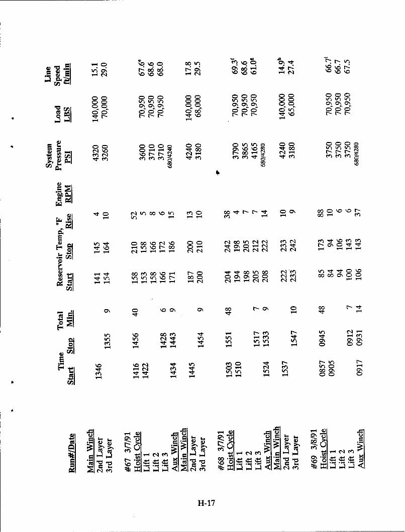
00 00 .00 ri~
0> % o Co 00 0tW') 0D 0000r
r-: 6 o6 t-. Cý 6 4 \ 0
Cc 0D0 D D 00
e~ ~ ~ r-r -r Itr --
N \O > -4 -- l 00 C\\ N 00~N eNt0W )W
mN NNN t-tNqr- - N 1-4 r- r-
00
~ 00 0'000\C 00 0 %00'0
"Id ' \ 0 r.I 0 ' 0' 00 0 N0'ýC 0 00N 'l
eqj '-4 '-44qN
'-4 co en 00 00r tl 0 0 Ne.d
"e ton %0 r0 00C qm 0 0Ceq N N~ veo N
D %D 0\4 C\ 0- 0\ C 000
\0 00 M Ieeq I, een le: It K ~
w-1
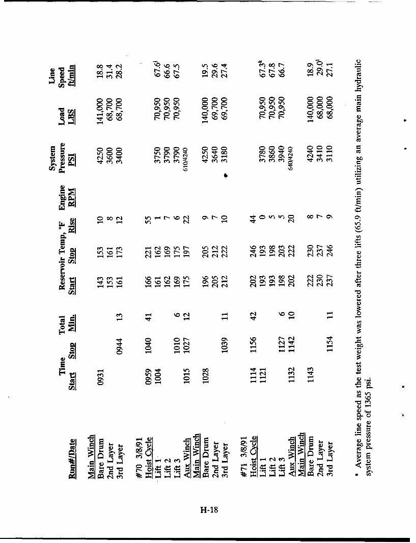
00ItN ro ) 0 r O0.Y
co-cz
000 CD D 00C)0 000)C)C)CCA\O C)-C r-~o V00 C
go~~~~o~' 000000 6 C \ \e 6o
R - -4 r.4I-
000 0000W)W)l 000 00 O \0000 tr-4T-4 c
- q .or 0 \ t l .
OC) 0N W) r-4 ýoN r-0 C)0t ) W V C 00 -C\ O\wir
en '-4 e ) )N\ en0 en C -N
ýN - ~ '-N \0 r- 7\ - "!tCh C ~~ 0 en e O -t-\N' -'- NN NqC4 - -4 -4N C1 q qeqe
4) t V) 0 \ \ \0%0r- \ 0\N ~O0 N 0\ C) e-e
f~- ~~4N~tt~'~.'r~N Nf~0N Nr N N
fnO t \0 NO \00 NC) 0
cccC) CD C CD T-
C) rCq
0\ "er W) r- en 4
enW -4N co n N0I 0 0 > C 0D r-4 r-4 r-4
C) - -- 0 1-
H-180
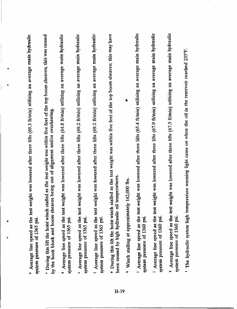
m. Uz ( ecc
bb 4) .- .
CC,,
44-
4-4 Co
0\ 4) 4) U
0 0
Ir4)
0 "o "0 "o"
N-4 -Q
04 0 0A .- .
4- 4- 4-c C z oc
'0 u '0 cc'. ~0'
.4- 0 . 4 4 .
en *- . - 4
T4 4 4D 4L)4) 4 4 .4 CD 4) 4 U, b c 4) 4) 4 4)
U,4- 0- U - - - -4
P= 6-a - (A I..*a 4- 0- 4D "
bb. bb. bo bo U. U-4) 0- 4) 4) 4) 4) 4 )Ce)
cc 4Z
bIbL ~ C ~4)S4)D 4) >) 4 -4 )4U-. U. U-U-. , U-U-En
4) u ~ 4) 4 4) ) 4H4)14
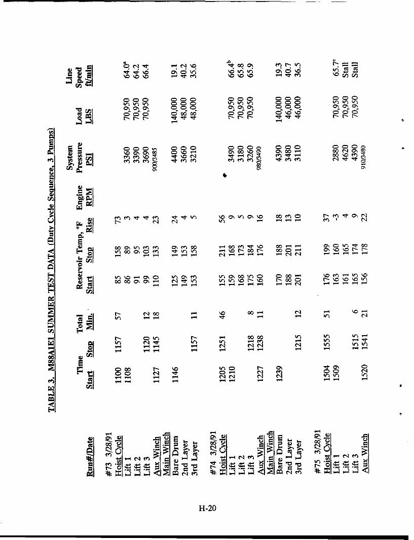
.0 u
Itt~O 000 O NO 000 O\\=0=000 0000 00 0%3O 00
0;N C5N tr-NN c
C) C> C) C) 0000 00 66 )O'\o )CDC
w \00~ 0\ý0 0\0 C \00 %0 0 00 r- 0~0 N \0
NA cn h 0 V*e tr4 q0t -00 No
- ci r- N- cq N
W)00 C\ 4= m t n-"4 N. rl 0r 00 ND",-q C-4 NNN e
We 00 000 \ c et )- 0r-\ r-Y. 00C - %-% ý "
w kn wl W) "-
T-.4 ~N tn W)V
CD 0H- co
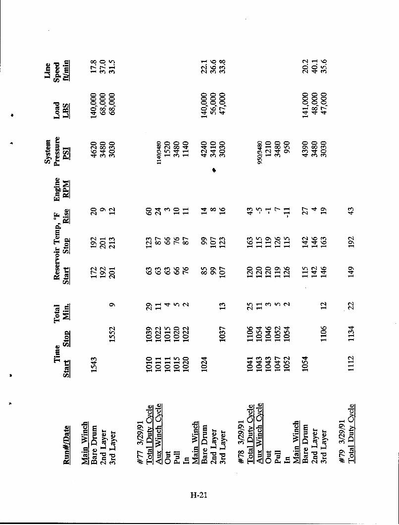
CR0 kq %'0 00 q14\NNYt-:4 \. v C C V
000 000 ýC C )C 0000 00 000 C C
ed~ 600 6 - t: ý0 -
N00 00cq00 00 00r. M( 400 W C\000e
0-0 N 0\Ot 0 NtOCAO '4' le C-4 'n t rI N It C n ýtC
C\4 N 00 %0Nr00 O\ CDN \0 N .O INt\
N 1 % V 0 - 0 C)4 \\NVýN\
v r-0\ C \0 o % %0 - 00C\ 0vq N e r'r 'd
in en Nq -- qc n 0W ti n0000ý0 0 0 0 0000 0 0
t m-D W ne -f d
"d, ~ ~ ' r- - - -4C4d d l ) W -
V)N 0~ NOC )CC C )C -
T-N'%q r- - a-- v4r4r4r-l?- - -
r-4 P=-21
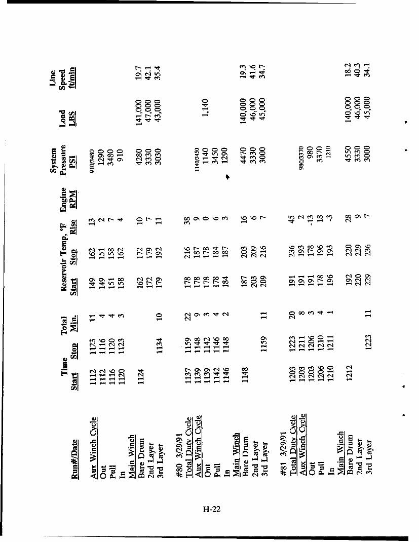
000 0i 0\T00q 00 0 t
000 0 00) DCDC 00
ccO z 0r C> %0V)'
'-4 V-4
064r-OO 00
W ".4 - 4 r- 4 r-- v-4 'j-4 '-4 r-4 '-I C14 e'-4 ". - - - CI
r- ~ eenC \c 0 V-4 00Mc~tV-0 ~ '-
Oýo'1~O CD M qO 0\00N'o0
r- -1 eqe ) ~ t l *W
P-4 ?-q r-. -4 v--4 r-4 r-- v-4 ?
et'c ý O\ Q1 00 m en en 0 C) 'NV-4~~~~00 0 -- -nenqtq,
r -4 - IV4 "4rqT-- - r- r- e-c'ql C1q C-14
r.44
C> 4aV4 .
H1-22
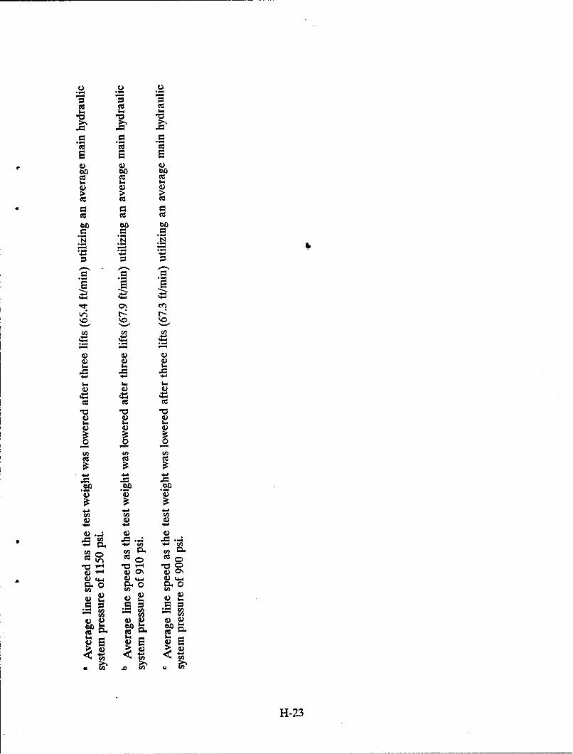
bb b bO
E
'0 '0 '0
V2 V) (n
h.b
cc 4o ) 4)
.0 r '0 C4) 4) 4) O4) 4) 44 V4) 4
o4 0 ý 04
4) 4) 4)
UH-2
TRIAL #81
M88A1E1 (vehicle P4)
29 March 91
H2
H-24
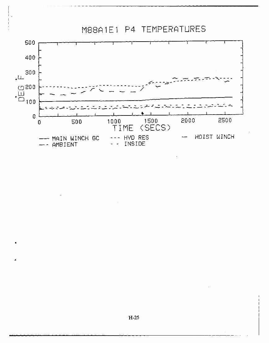
N88AIE1 P4 TENPERA~TURES
Soo
400
300
_D 2 0 0 . . . . . ..--- --- . . . . . . . .
- - - - - - - - - - - - -
"CD10 0 2
0 1 A
0 500 1000 1500 2000 2500
TIME (SECS)-MAIN WINCH GC --- HYD RES - HOIST WINCH
--- AMBIENT - INSIDE
H-25
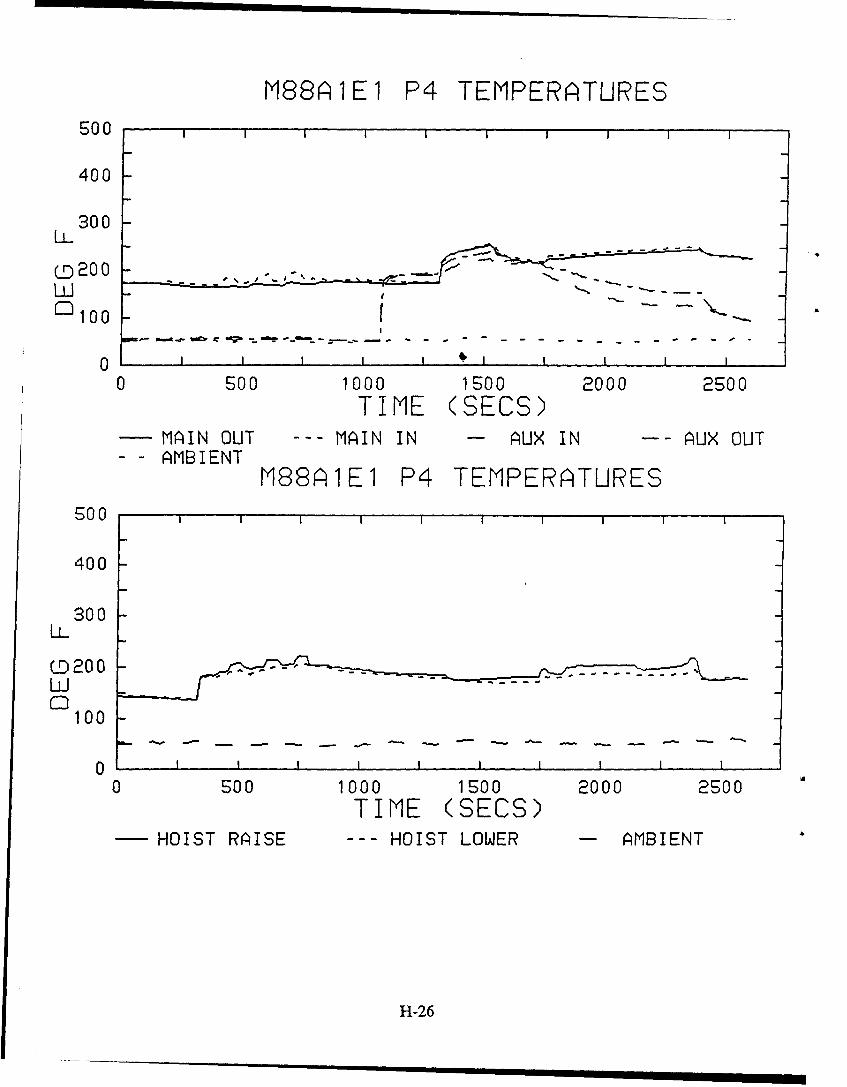
M88AI1E1 P4 TEMPERATURES500
400
300
ILI0 200
ft" Web -C
0 500 1000 1500 2000 2500
TIME (SECS)- MAIN OUT --- MAIN IN -- AUX IN - A- iUX OUT- - AMBIENT
[188AIEI P4 TEMPERATURES500
400
300EL
0D20 0LLI
100
00 O00 1000 1500 2000 2500
TIME (SECS)- HOIST RAISE --- HOIST LOWER - AMBIENT
H-26
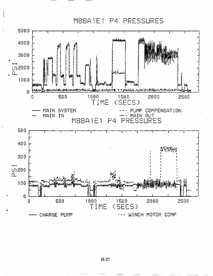
M88Ari1El P4 PRESSURESSO00
4000 -
3000
Cof20 00
1000
0 ~ ~ ~J r"A~4 4,sr , 4 44Ji&AJ4'Ai~iL j~~'h
0 500 1000 1500 2000 2500TIME (SECS)
-MAIN SYSTEM --- PUMP COMPENSATION- MAIN IN - - MAIN OUT
M88A 1E1 P4 PRESSURES500
400
300
CO 200 0
10 0 - ,, ,.
0I to.•I I
0 500 1000 1500 2000 2S00TIME (SECS)
- CHARGE PUMP --- WINCH MOTOR COMP
H-27
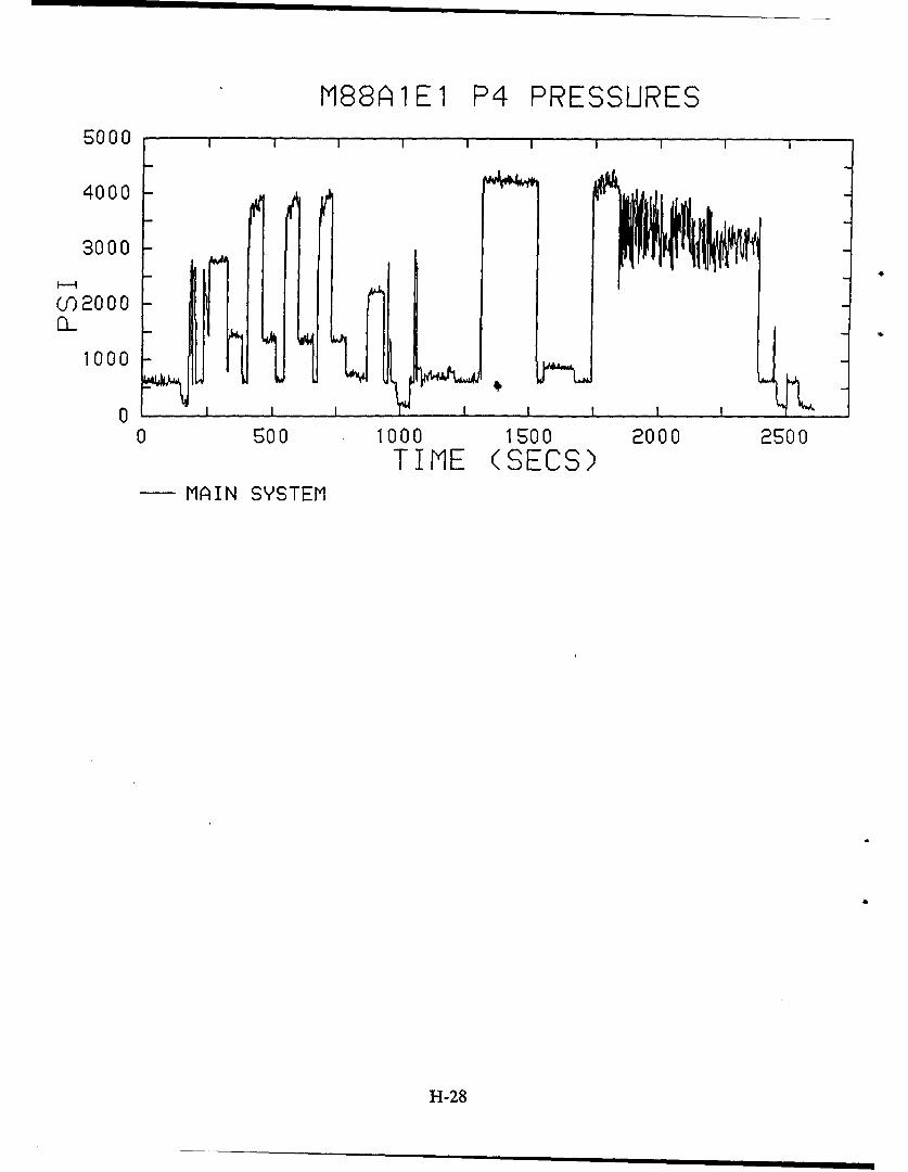
M88A1E1 P4 PRESSURES5000
4000
3000
(0) 2000
1000
00 Soo 1000 1500 2000 2500
TIME (SECS)- MLAIN SYSTEM
H-28
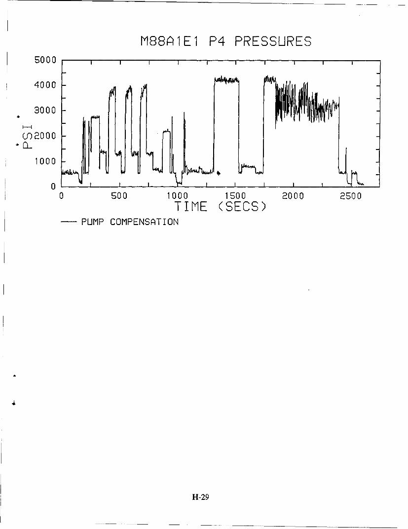
[88Al1E1 P4 PRESSURES
4000
3000
0-)2000
1000
00 500 1000 1500 2000 2500
TIME (SECS)PUMP COMPENSATION
H-29
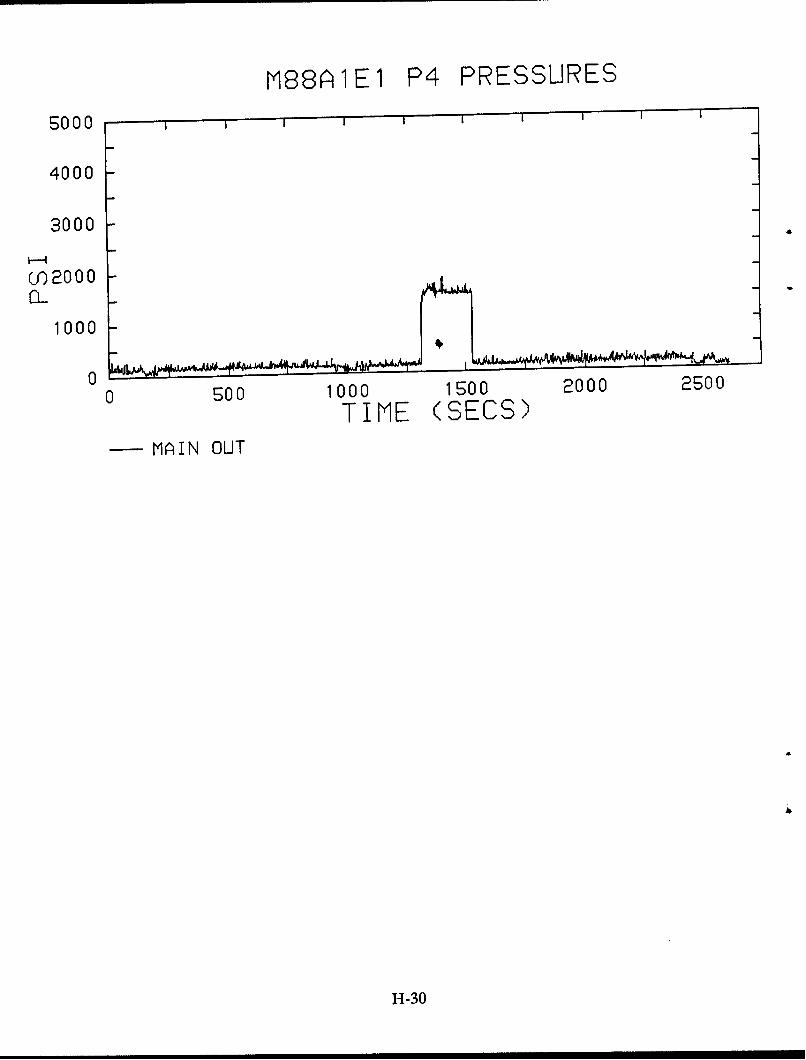
M88AI1EI P4 PRESSURES
5000
4000-
3000
(0 2000
10 0 0 !
0-0 500 1000 1500 2000 2500
TIME (SECS)MAIN OUT
H-30
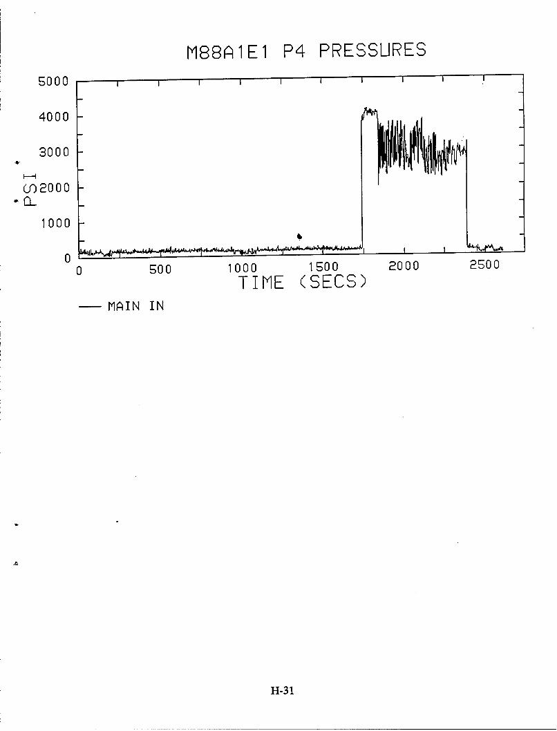
M88AIlEl P4 PRESSURES
5000
4000-
3000
3n 2000
1000
00 500 1000 1500 2000 2500
TIME (SECS)- MAIN IN
H-31
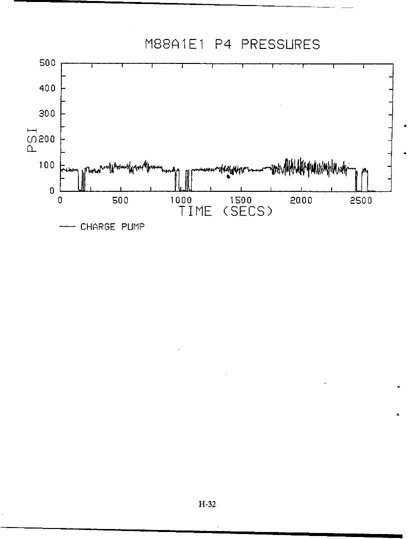
M88A1E1 P4 PRESSURESEQo 0
400
300(f20 0
100 -
0 Soo 1000 1500 2000 2500TIME (SECS)
- CHARGE PUMP
H-32
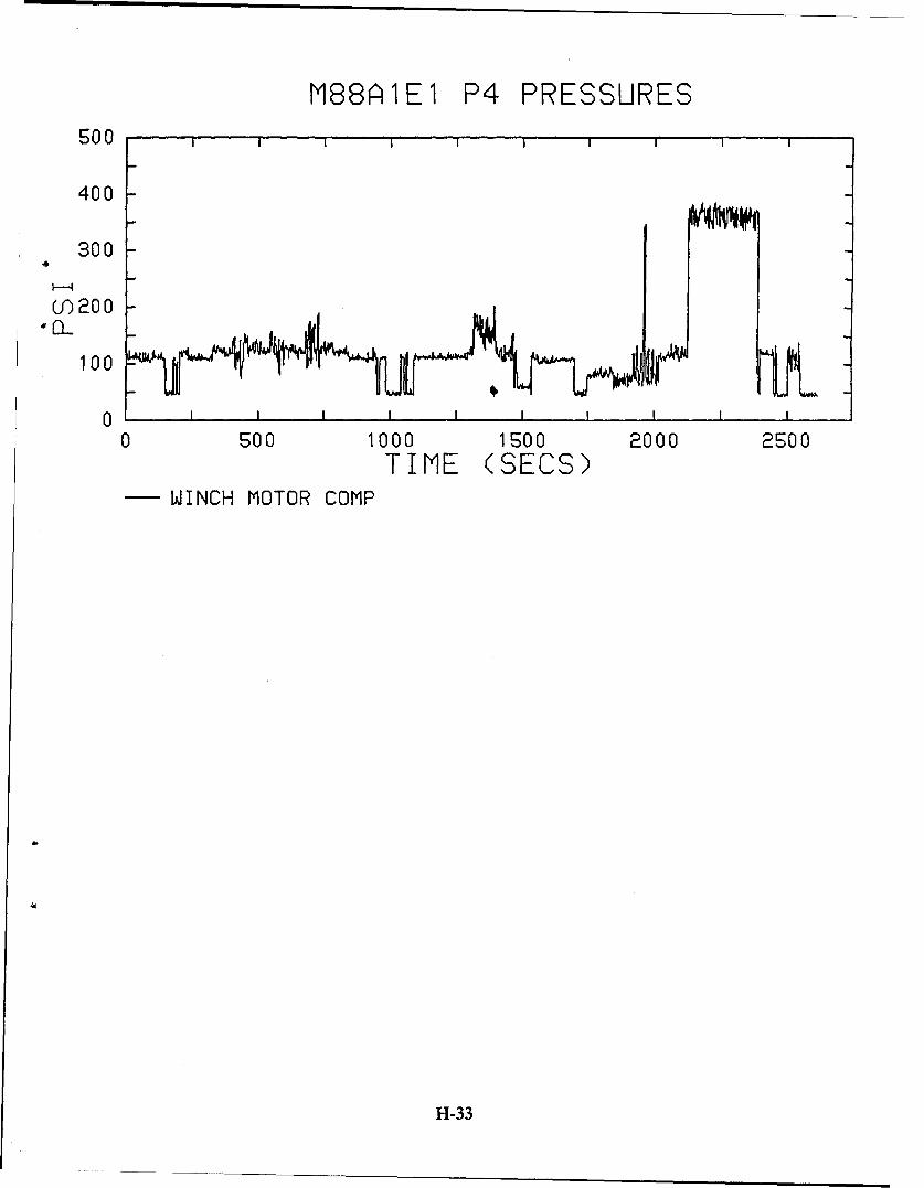
M88A1E1 P4 PRESSURES500
400
300
0f2004 nL100
0 I I I I I, I I
0 500 1000 1500 2000 2500TIME (SECS)
- WINCH MOTOR COMP
H-33
M88AI1EI P4 ENGINE SPEED
3000
2400
"1800aI.
1200
600
0 --. A ------- I
0 500 1000 1500 2000 2500
TIME (SECS)
H-34
TRIAL #81
M88A1E1 (vehicle P4)
29 March 91
H-35
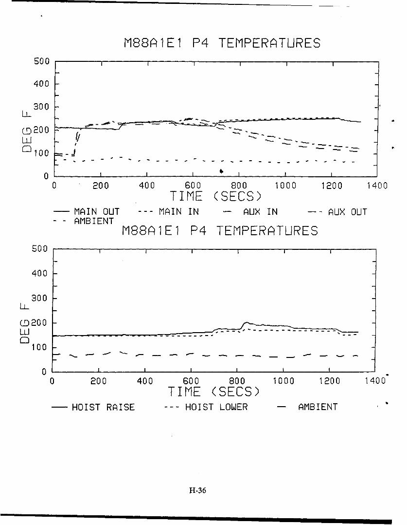
M88AIE1 P4 TEMPERATURESS00
400
300
•200
Ei
0 I I I $ I
0 200 400 600 800 1000 1200 1400TIME (SECS)
M MAIN OUT --- MAIN IN A- AUX IN A-- AUX OUT- - AMBIENT
M88AlEl P4 TEMPERATURES500
400
300LL
0200
100
0 .. ... .I I I III
0 200 400 600 800 1000 1200 1400TIME (SECS)
HOIST RAISE --- HOIST LOWER - AMBIENT
H-36
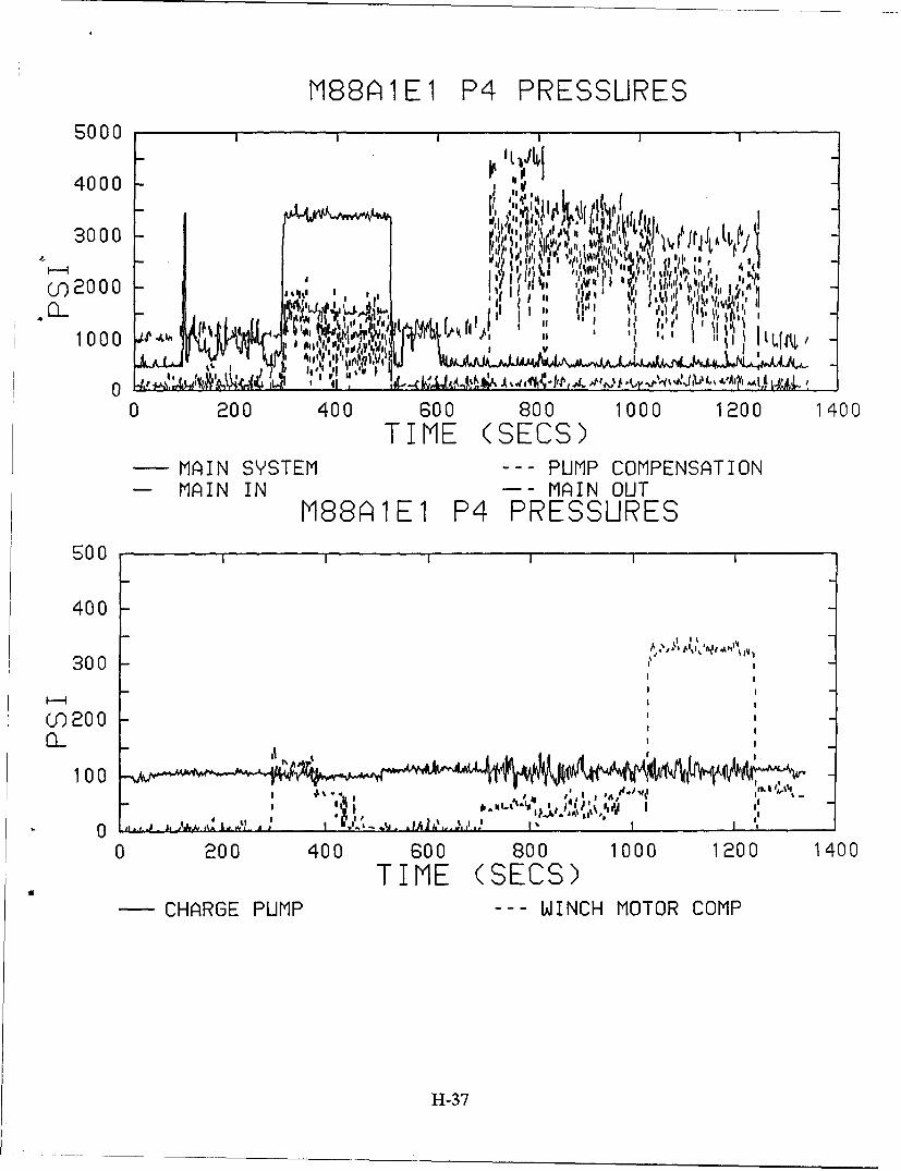
M88Ai1E1 P4 PRESSURES
5000
4000 -v
I v
N Ji l '14• ,; t , • • ,Cf 0 00 - ',, ,•, rJ•,i'
hl II IllII I, vtI ,I hi' " ,i
0 200 400 600 800 1000 1200 1400
TIME (SECS)-MAiIN SYSTEM - -- PUMP COMPENSATION
- MAIN IN - - MAiIN OUTM88A~1E1 P4 PRESSURES
500I II
400
300 s~~I ~
CO)20 0
100
U,,
0 200 400 600 800 1000 1200 1400
TIME (SECS)CH1ARGE PUMP --- WINCH MOTOR COMP
H1-37
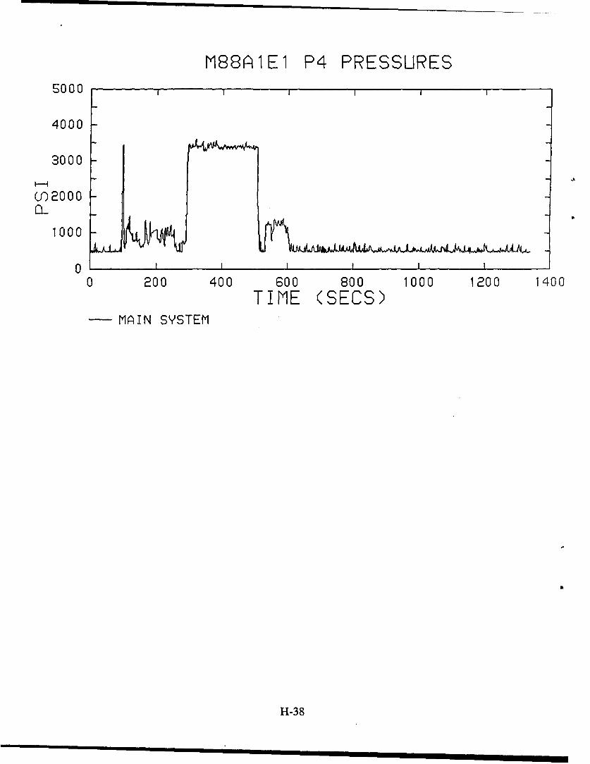
M88AIlEl P4 PRESSURESSO00
4000
3000
I--I
()2000
1000
00 200 400 600 800 1000 1200 1400
TIME (SECS)MAIN SYSTEM
H-38
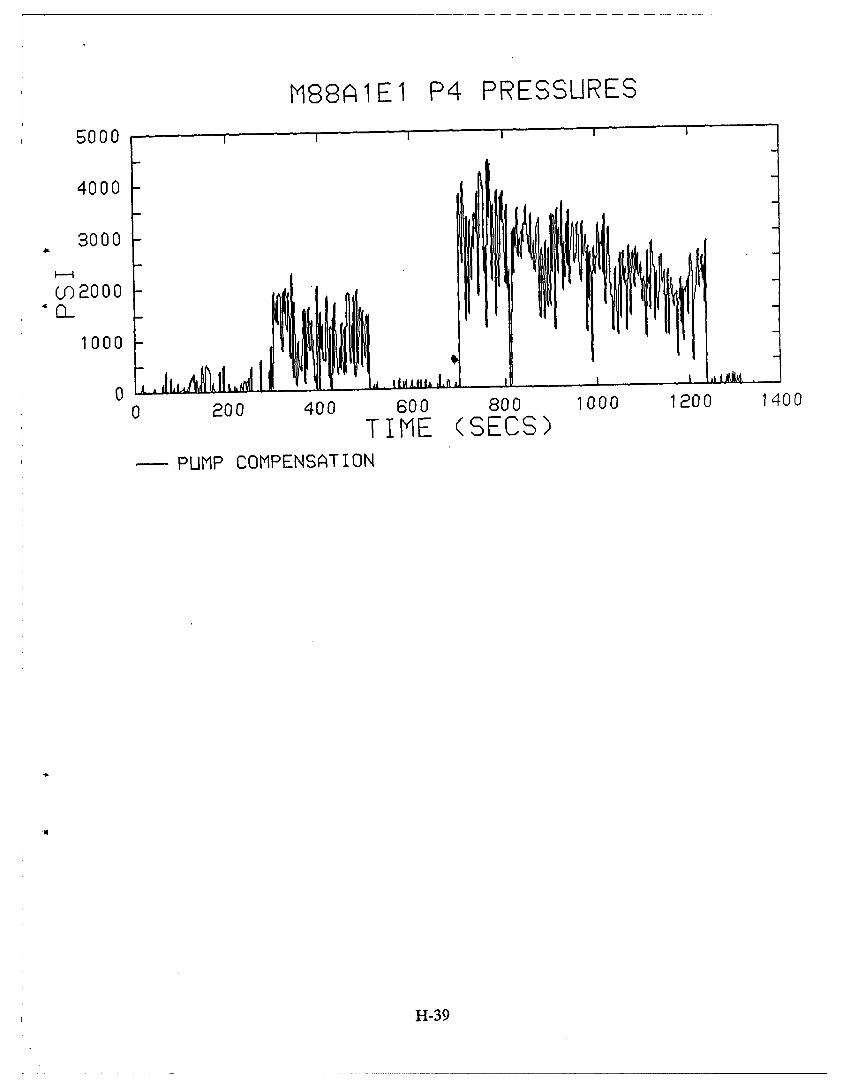
M88AIE1 P4 PRESSURES5000 Iiil," '
4000
3000
0') 2000
4 L1000
0 200 400 600 800 1000 1200 1400
TIME (SECS)PUMP COMPENSATION
H-39
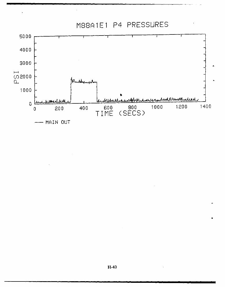
M88A1E1 P4 PRESSURES
5000
4000
3000
Cf) 20 00
1000
0 200 400 600 800 1000 1200 1400
TIME (SECS)MAIN OUT
H-40
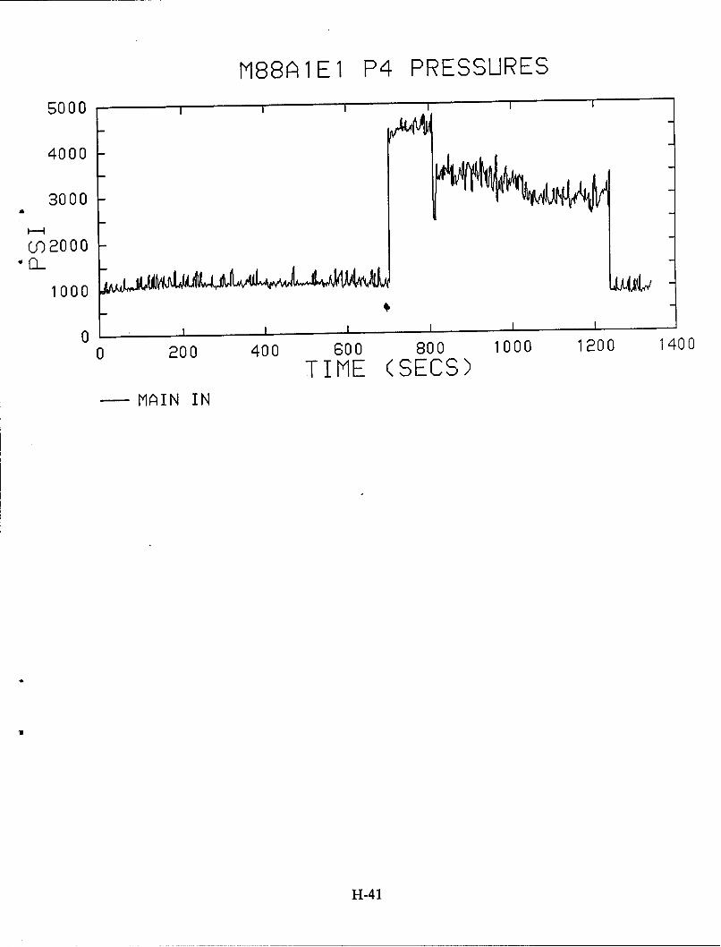
M88AI1EI P4 PRESSURES
5000
4000
3000
(O 2000
1000
0 200 400 600 800 1000 1200 1400
TIME (SECS)- MAIN IN
H-41
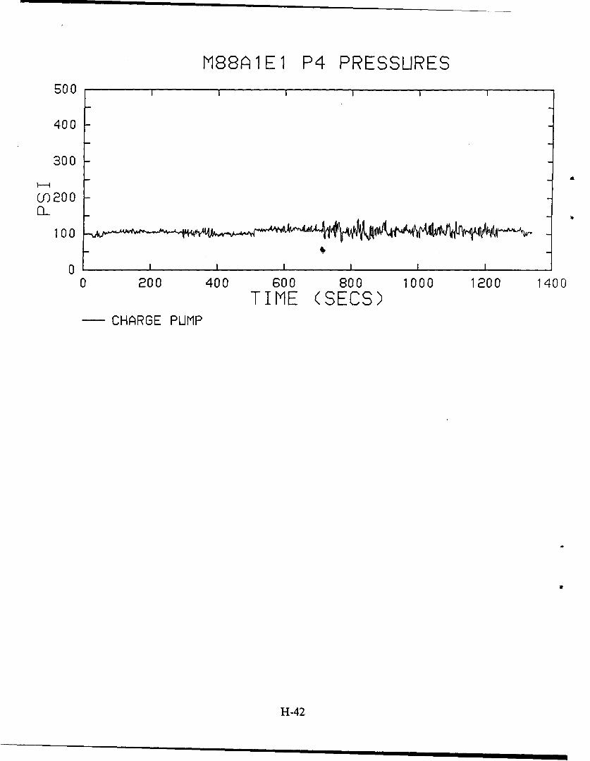
M88AIE1 P4 PRESSURES500
400
300
f) 200
100
0 , ,i , , ,I I I I
0 200 400 600 800 1000 1200 1400TIME (SECS)
- CHARGE PUMP
H-42
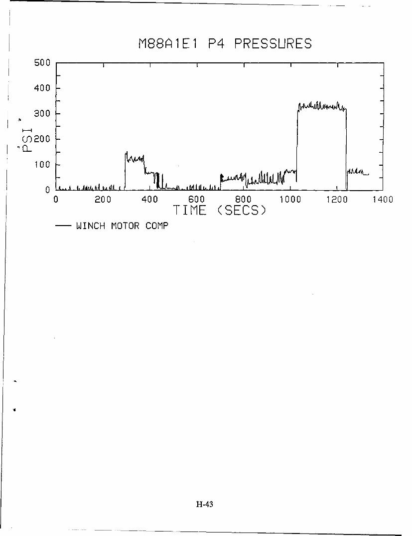
M88A1E1 P4 PRESSURES500
400
300
(f)200
100
0 rLI__. t__d U L
0 200 400 600 800 1000 1200 1400TIME (SECS)
-WINCH MOTOR COMP
H-43
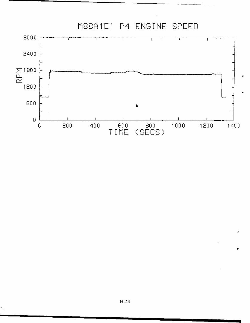
M88AIEI P4 ENGINE SPEED3000
2400
7"1800
1200
600O0 -
0 I I I I I i
0 200 400 600 800 1000 1200 1400TIME (SECS)
H-44
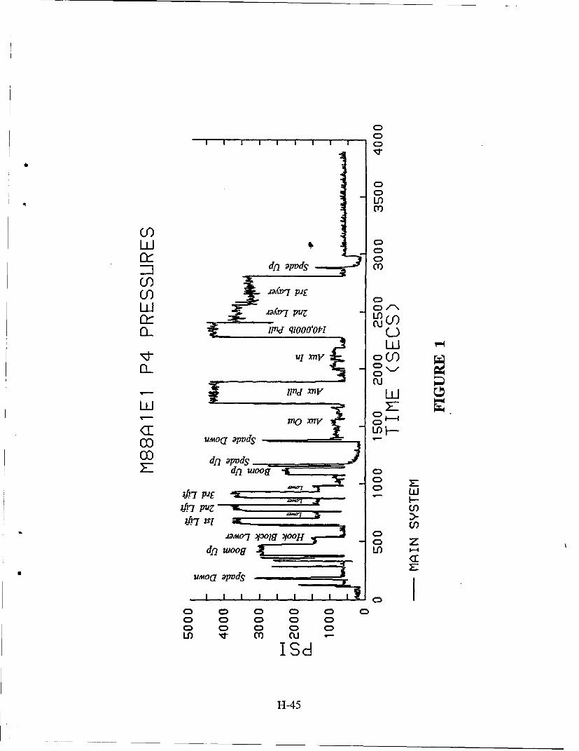
CD
LI)
CCD
0)
co C~C>
l~ndqloolopr(U
lin xnv wý(f
CCon~ CD
417 pig
S UA4OU apvdS
oD oD 0 0 00n 0 0 0 C
0 0 0 0LI)> 0) UJJ?'7IPd
;J?7 11-4U
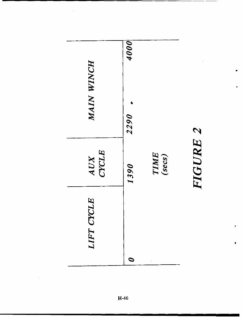
*
z
z
a
H-46
APPENDIX I
Three-Pump Modification
I-i
1-2
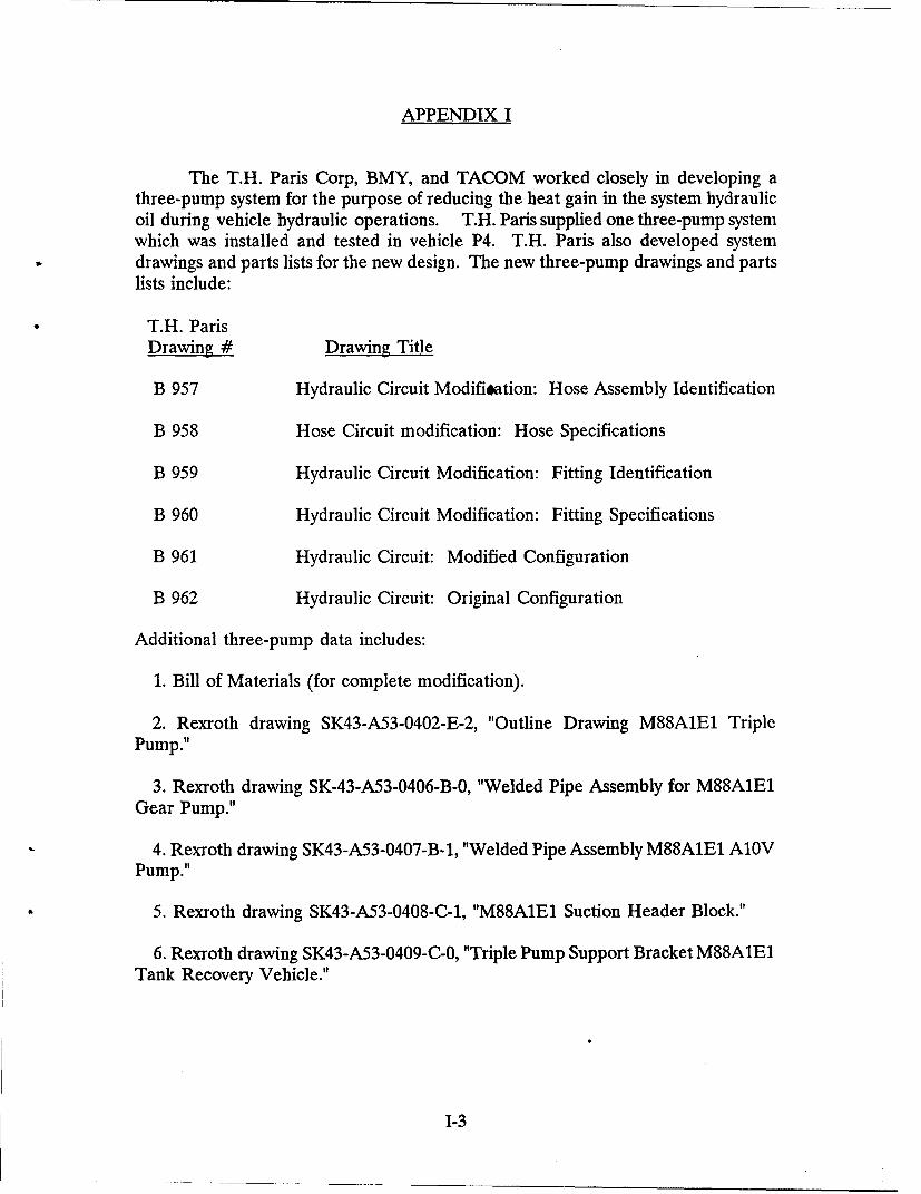
APPENDIX I
The T.H. Paris Corp, BMY, and TACOM worked closely in developing athree-pump system for the purpose of reducing the heat gain in the system hydraulicoil during vehicle hydraulic operations. T.H. Paris supplied one three-pump systemwhich was installed and tested in vehicle P4. T.H. Paris also developed systemdrawings and parts lists for the new design. The new three-pump drawings and partslists include:
T.H. Paris
Drawing # Drawing Title
B 957 Hydraulic Circuit Modifisation: Hose Assembly Identification
B 958 Hose Circuit modification: Hose Specifications
B 959 Hydraulic Circuit Modification: Fitting Identification
B 960 Hydraulic Circuit Modification: Fitting Specifications
B 961 Hydraulic Circuit: Modified Configuration
B 962 Hydraulic Circuit: Original Configuration
Additional three-pump data includes:
1. Bill of Materials (for complete modification).
2. Rexroth drawing SK43-A53-0402-E-2, "Outline Drawing M88A1E1 TriplePump."
3. Rexroth drawing SK-43-A53-0406-B-0, "Welded Pipe Assembly for M88A1E1Gear Pump."
4. Rexroth drawing SK43-A53-0407-B-1, "Welded Pipe Assembly M88A1E1 A10VPump."
5. Rexroth drawing SK43-A53-0408-C-1, "M88A1E1 Suction Header Block."
6. Rexroth drawing SK43-A53-0409-C-0, "Triple Pump Support Bracket M88A1E1Tank Recovery Vehicle."
1-3
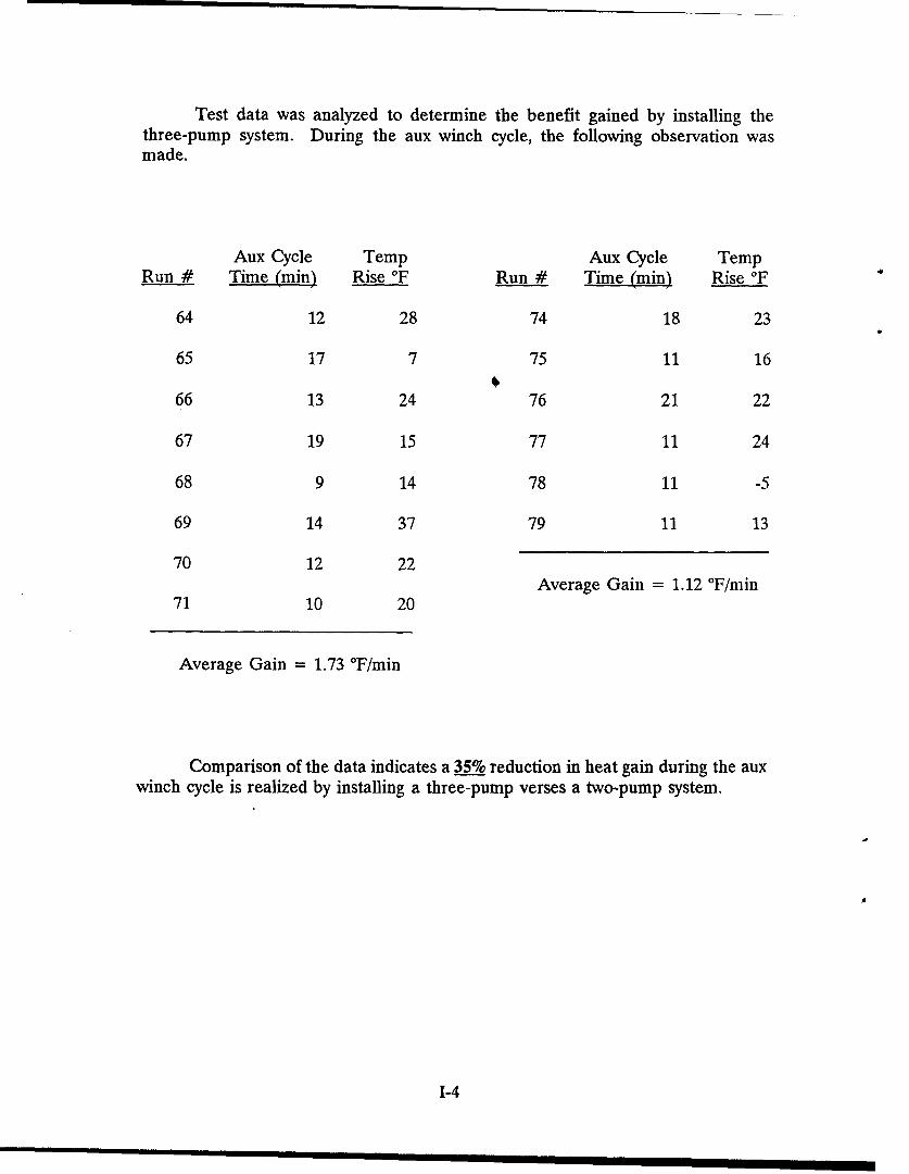
Test data was analyzed to determine the benefit gained by installing thethree-pump system. During the aux winch cycle, the following observation wasmade.
Aux Cycle Temp Aux Cycle TempRun # Time (min) Rise 'F Run # Time (mi) Rise 'F
64 12 28 74 18 23
65 17 7 75 11 16
66 13 24 76 21 22
67 19 15 77 11 24
68 9 14 78 11 -5
69 14 37 79 11 13
70 12 22Average Gain = 1.12 °F/min
71 10 20
Average Gain = 1.73 °F/min
Comparison of the data indicates a 35% reduction in heat gain during the auxwinch cycle is realized by installing a three-pump verses a two-pump system.
1-4
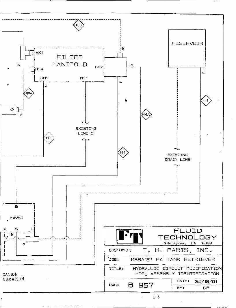
RESERVO'IR
AXl
FILTERa I MANIFOLD CH2! a.
4C I aH a.
L x/ L1 sIN5
a
100A
0>H
b 4A
EXISTING
LINE 5
______________EXISTING
DRAIN LINE
-------------- ---------------------------------------------------
B
A4VSO
X L . FLUID. '-.."- .TECHNOLOGY
r"a. Philadelphia , PA 19120FIICUSTOMER: T. H. PATRI 9• INC.
'JOB: MBBA1E1 P4 TANK RETRIEVER
TITLE: HYDRAULIC CIRCUIT MODIFICATION
C ATION HOSE ASSEMBLY IDENTIFICATIONORMATION - DATE: 04/10/91
DWG: B 957 BY: DP
1-5
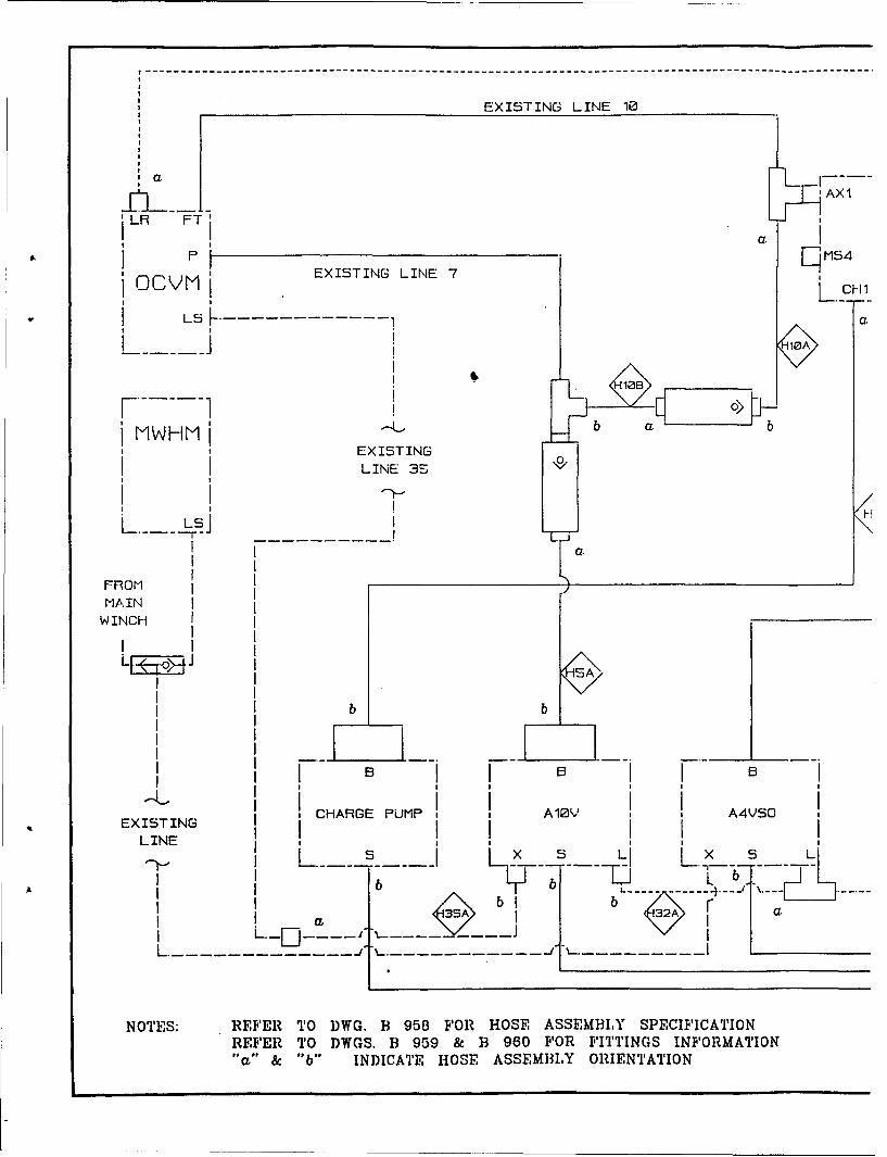
EXISTING LINE 10
I~l 'AX1
' LR FTI
i P I MS4EXISTING LINE 7I OCVMI .. 2-R
LS - - --
MWHMI b bEXISTING
LINE 35
S LS]
FROMMAIN
WINCH
Ib bB B
II II III 'I I I II.L I I AlYI I
,CHARGE PUMP , , A10•V I A4VSO
EXISTING I CHREPMLINE , I
I I b I b Lb
I sI 35 I r a.
L 7- ---------
NOTES: REFER TO DWG. B 958 FOR HOSE ASSEMBILY SPECIFICATIONREFER TO DWGS. B 959 & B 960 FOR FITTINGS INFORMATION"a" & "b" INI)ICATE HOSE ASSEMBLY ORIENTATION
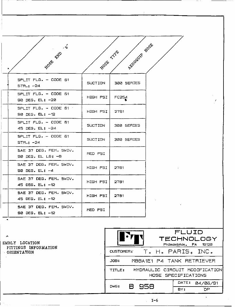
SPLIT FLG. - CODE 615TR; 24SUCTION 300 SERIES
SPLIT FLG. - CODE 61 HIH P FC24
90 DEG. EL; -20
SPLIT FLG. - CODE 61
S SAE 37 DEG. FEM. SWIM. MEPI
HIGH PSI 28
SLAE 37 DE. FEM. WIV.
908£ DEG. EL; -4HIHPI 28
SAE 37 DEG. FEM. SWIV.
I SA 37BEG FE. SIV. HIGH PSI 276145 DEG. EL; -12
SAE 37 DEG. FEM. SWIV.
45TDE. -24 -1
SAE 37 DEG. FEM. SWIV.MED PSI
90 DEG. EL; -12
SFl UID
"EBYLCTO F TECHNOLOGYEMIYTIG INFATORMTO Philadelphin, PA 19120
ORIENTATION CUSTOMER,.* T,, H. PARIS, INC.
JOB: MBIBA1E1 P4 TANK RETRIEVER
TITLE: HYDRAULIC CIRCUIT MODIFICATIONHOSE SPECIFICATION7
E 37 DE DATEE: 04/0/IV14w-EGEL;BY: -DP
1-6
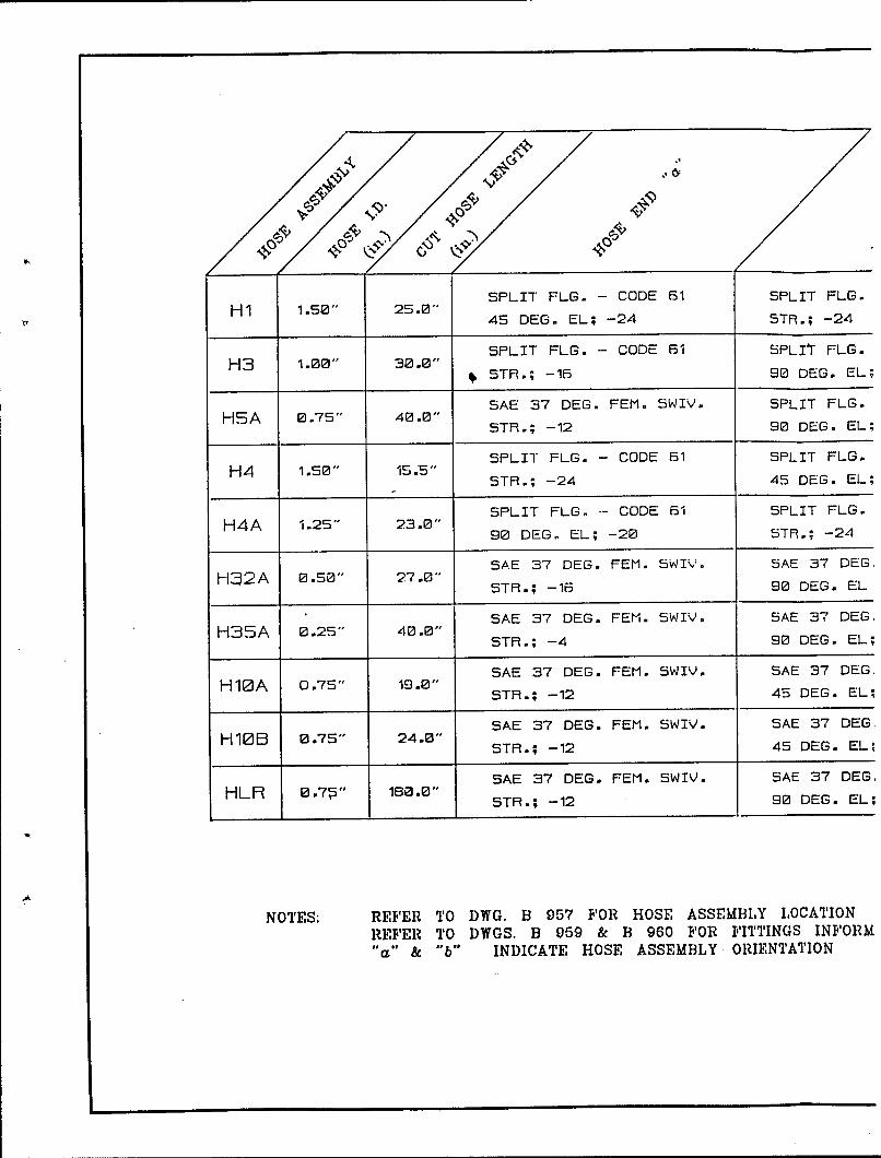
4 ý
SPLIT FLG. - CODE 61 SPLIT FLG.Hi1 1 .50" 25.0"
45 DEG. EL; -24 STR.; -24
SPLIT FLG. - CODE 61 SPLIT FLG.H3 1.00" 30.0"
, STR.; -16 90 DEG. EL;
SAE 37 DEG. FEM. SWIV. SPLIT FLG.HSA 0.75" 40.0""
STR.; -12 90 DEG. EL;
SPLIT FLG. - CODE 61 SPLIT FLG.H4 1.50" 15.5"
STR.; -24 45 DEG. EL;
SPLIT FLG. CODE 61 SPLIT FLG.
H4A 1.25" 23.0"90 DEG. EL; -20 STR.; -24
SAE 37 DEG. FEM. SWIV. 5AE 37 DEGHI32A 0.,50" 27.0"STR.; -16 90 DEG. EL
SAE 37 DEG. FEM. SWIV. SAE 3"7 DEG
H35A 0.25" 40.0"STR.; -4 90 DEG. EL;
SAE 37 DEG. FEM. SWIY. SAE 37 DEGH10A 0.75" 19.01"
STR.; -12 45 DEG. EL;
SAE 37 DEG. FEM. SWIV. SAE 37 DEG.
H10B 0.75" 241.0"STR.; -12 45 DEG. EL;
SAE 37 DEG. FEM. SWIV. SAE 37 DEG
HLR 0.,7h" 180.0e"STR.; -12 90 DEG. EL;
NOTES: REFER TO DWG. B 957 FOR HOSE ASSEMBLY L1 OCATIONREFER TO DWGS. B 959 & B 960 FOR FITTINGS INFORM"&" & "b" INDICATE HOSE ASSEMBLY. ORIENTATION
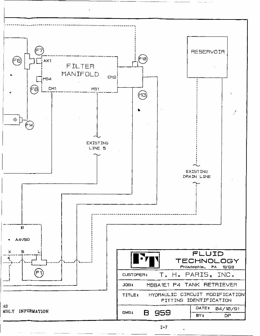
,RESERVOIR
SAX1 IJFILTER
M4 MANIFOLD C25 CH1
)E3 -- - - - - - - - -MS 1 - - --
EXISTINGLINE 5
EXISTING
DRAIN LINE
-------------------- ---------------------------------------------------
". A4VSO
x - LI FLUID•---- . .. TECHNOLOGY
PhIladelphia, PA 19120CUSTOMER: T. H. PARI,• INC.
JOB:- MBBA1E1 P4 TANK RETRIEVER
TITLE: HYDRAULIC CIRCUIT MODIFICATIONFITTING IDENTIFICATION
.is DATE:0 4/10/91MtIY INF'ORMABION DWG: B 959 BY: DP
1-7
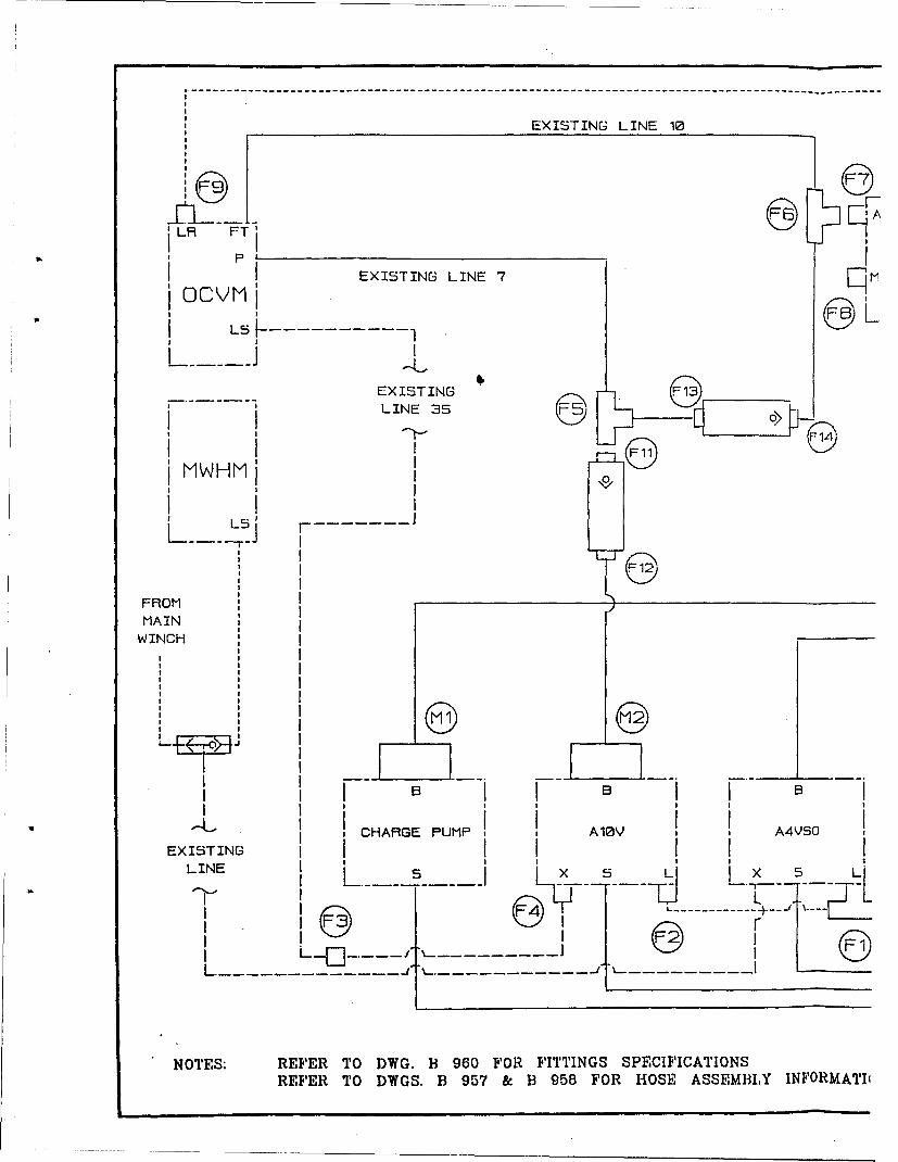
EXISTING LINE 10
LR FTS P
EXISTINGLINE 35
I
I
I L I I
SI I.I I
MAIN0EXISTING C P4VS
W INCH 5
L -- - - - -IL|" - , -
II II I
R FI I B I9 B I I B I, CHARGE PUMP , , AlOYV , , A4VSO
EXISTING I I I I I I
LIN E S iL x_ __ Li x L
, I K... ..... T-...'' .. L_*
I
L.-- ------------ : ---- J
NOTES: REFER TO D)WG. B 960 FOR FITTINGS SPECIF 1ICATIONS
REFER TO DWGS. B 957 & B 958 FOR HOSE ASSEMLvIY INF'ORMATI
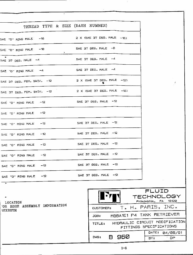
THREAD) TYPE & SIZE (DASH NUMBER)
SAE "0" RING MALE -16 2 X (SAE 37 DEG. MALE -16)
SAE "0" RING MALE -10 SAE 37 DEG. MALE -8
SAE 3-7 DEG. MALE -4 SAE 37 DEG. MALE -4
SAr "0" RING MALE -4 SAE 37 DEG. MALE -A
SAE 37 DEG. FEM. SWIV. -12 2 X (SAE 37 DEG. MALE -12)
SAE 37 DEG. FEM. SWIV. -12 2 X (SAE 37 DEG. MALE -16)
SAE "0" RING MALE -12 SAE 37 DEG. MALE -12
SAE "0' RING MALE -12
5AE "0" RING MALE -12 SAE 37 DEG. MALE -12
SAE "0" RING MALE -12 SAE 37 DEG. MALE -12
SAE "0" RING MALE -12 SAE 37 DEG. MALE -12
SAE "0" RING MALE -12 SAE 37 DEG. MALE -12
SAE "0" RING MALE -12 SAE 37 DEG. MALE -12
SAE "0" RING MALE -12 SAE 37 DEG. MALE -12
FFLUID
C-1 TECHNOLOGYIOCATION Philadelphia. PA 19120
'OR HOSE ASSEMBLY INFORMATIONZEXROTH CUSTOMER: T. H. PARI5 9 INC.
JOB: MBBAlEl P4 TANK RETRIEVER
TITLE: HYDRAULIC CIRCUIT MODIFICATION
FITTINGS SPECIFICATIONS
DATE: 04/08/91
DWG: B 960 BY: DP
1-8
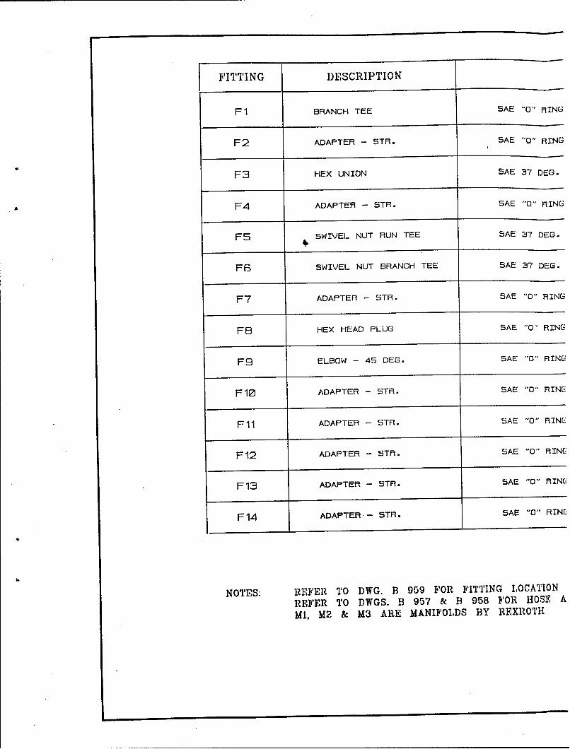
FITTING DESCRIPTION
Fl BRANCH TEE SAE "0" RING
F2 ADAPTER - STR. SAE "0" RING
F3 HEX UNION SAE 37 DEG.
F4 ADAPTER - STR. SAE "0" RING
F5 SWIVEL NUT RUN TEE SAE 37 DEG.
F6 SWIVEL NUT BRANCH TEE SAE 37 DEG.
F7 ADAPTER - STR. SAE "0" RING
F8 HEX HEAD PLUG SAE "O" RING
F9 ELBOW - 45 DEG. SAE "O" RING
F10 ADAPTER - STR. SAE "0" RING
Fll ADAPTER - STR. SAE "0" RING
F12 ADAPTER - STR. SAE "0" RINCk
F13 ADAPTER - STR. SAE "0" RINf_
F14 ADAPTER-- STR. SAE "0" RINE
NOTES: REFER TO DWG. B 959 FOR FITTING ILOCATION
REFER TO DWGS. B 957 & B 958 FOR HOSE A
Mi. M2 & M3 ARE MANIFOLDS BY REXROTH
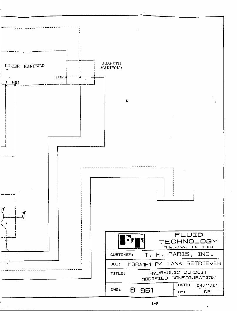
F0IITER MANJII"OID ERTMANIPFO1.)
CH2I:Hl MS1.
~~~~1
I• -- ,,-- -------------------------
... .hidephim. PA 19120
CUSTOMER: T. H. PARIS9 INC.r JOB: MB6A1E1 P4 TANK RETRIEVER
TITLE: HYDRAULIC CIRCUIT
MODIFIED CONFIGURATIONSODATE: 04/11/91
DWG: BY961IBY: DP
1-9
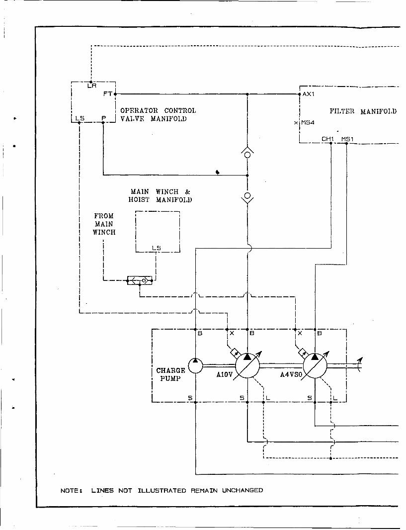
LR F•I,T , AX1
OPERATOR CONTROL I FILTER MANIFOLDL ___J VALVE MANIFOLD) xM54
L CH1 MS1
MAIN WINCH &HOIST MANIFOLD
FROM I
MAINWINCH
I I I
I I IL L
L --- ---- ---
II I
ICHARGE A1" V 0A4VSOPUMP
S• L 5 L/
I--
---------------------------
NOTE: LINES NOT ILLUSTRATED REMAIN UNCHANGED
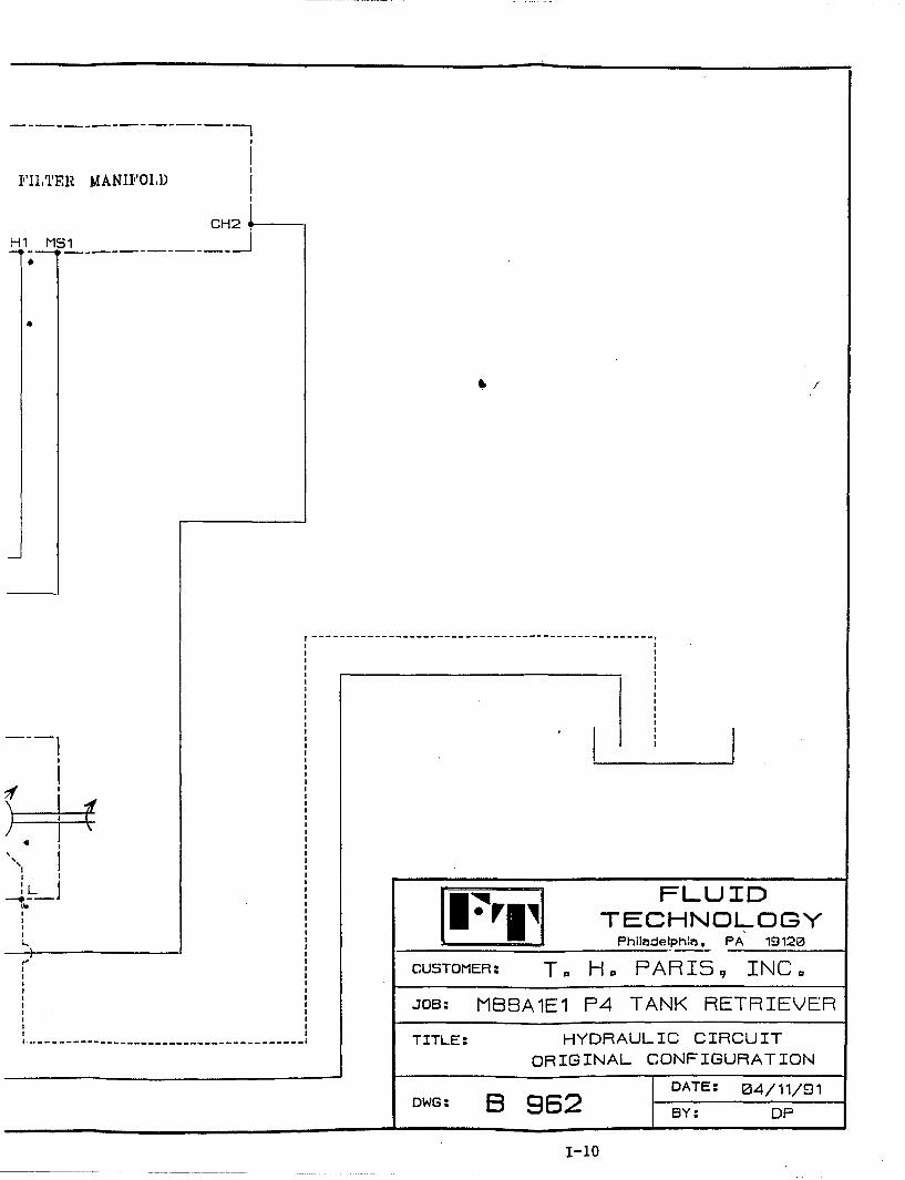
I'I1TER MANII'O1,I)
CH2H MS1J
*
/ ] •
- -
"_L_ FLUIDTECHNOLOGY
Philadelphim. PA 19120
"CUSTOMER: T. H. PARIS 9 INC.JOB: MSBA1E1 P4 TANK RETRIEVER
TITLE: HYDRAULIC CIRCUIT
ORIGINAL CONFIGURATION
DATE: 04/11/91DWG: B 962 'BY: DP
1-10
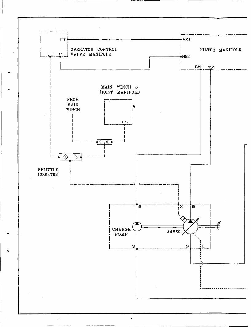
I FT AX1
OPERATOR CONTROL, j FILTER MANIFO1,DL ~ KPI VALVE MANIFOLD MS4
7 L.. -H1 MS4
MAIN WINCH &HOIST MANIFOLD
FROM - iIMAIN
WINCH ,Li i1
I .-----
SHUTTLE12364792 I
L-----------------"B----------- -E---i
CHARGE Av~PUMP
- - -
--- -- --- -- --- -- --
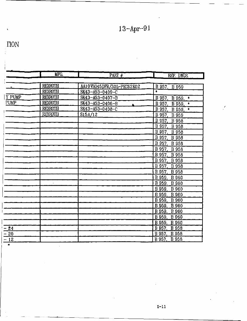
13-Apr-9 i
nION
MFG. PART # REF. DWGS.
__ _ _ REXROTiI A10 VSO45DFR/30L-PKC62KO2 B 957, B 959REXM.TI SK43-A53-0409-C *
Y PUMP RXOTI SK43-A53-0407-B B 957, B 959, *PUMP REXROTIH SK43-A53-0406-B B 957, B 959, *
P__DTEI SK43-A53-0408-C B 957, B 959, *_ REXROTH S15A/12 B 957, B 959B 957, B 958
_..........._B 957, B 958_....._B 957, B 958_....._B 957, B 958_.....B 957, B 958
B 957, B 958B 957, B 958B 957, B 958B 957, B 958B 957, B 958B 959, B 960B 959, B 960
_ B 959, B 960_.... ._B 959 B 960
B 959, B 960B 959, B 960
_ B 959, B 960B 959, B 960B 959, B 960
- t4B 957, B 958- 20 B 957, B 958- 12 B 957, B 958
,4 ,,,
I-il
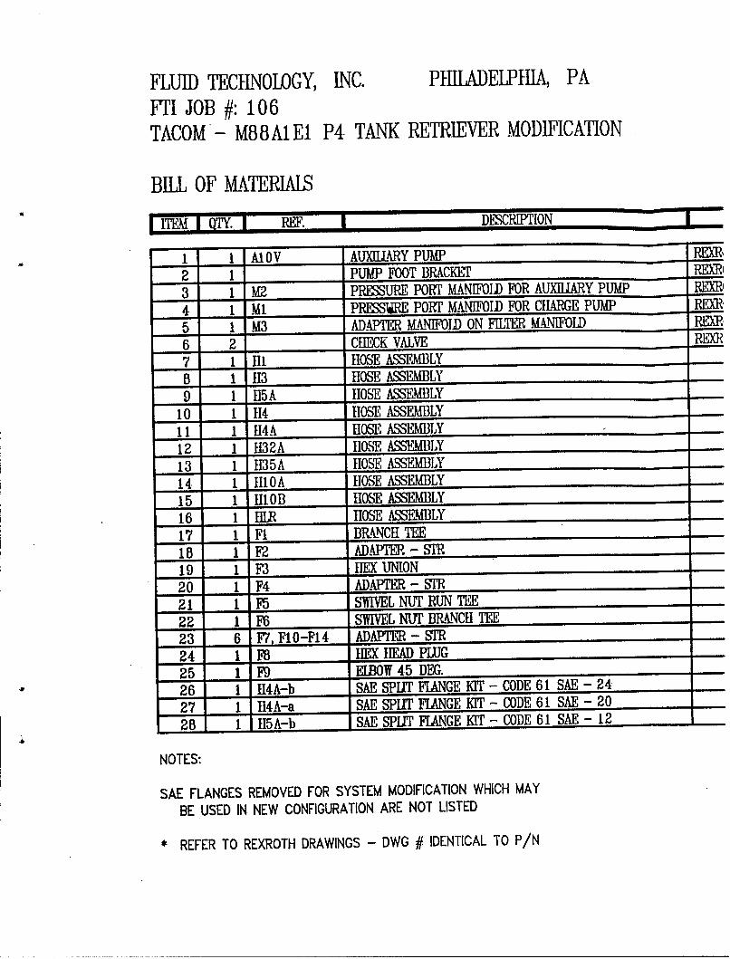
FLUID TECHNOLOGY, INC. PHILADELPIIA, PAFTI JOB #: 106TACOM*- M88AIE1 P4 T.ANK RETRIEVER MODIFICATION
BILL OF MAWTERIALS
I ITEM 1 OTY. I REF. | DESCRIPTION
1 1 A1OV AUXIUARY PUMP R[i
2 1 PUMP FOOT BRACKET RpEXR3 1 M2 PRINSURE PORT KNIFOUID FOR AUXILIARY PUMP RXR,
4 1 Ml PRESS", PORT MANIFOLD FOR CHiARGE PUMP REM,
5 1 M3 AD.APTER MANIFOlD ON FILTER MANIFOILD RP,,
6 2 CHECK VALVE REXR
7 1 111 ROSE ASSEIMBLY8 1 113 HOSE ASSEIMBLY9 1 15A IOS'E ASSEMBLY
10 1 114 HOSE ASSEMBLY11 1 1I4A tlOSE ASSEMBLY12 1 1132A lOS ASSEMBILY13 1 I135A 10SE ASS•XMLY14 1 1110A IhOSE ASSEMBLY15 1 1110B HOSE ASSEMBLY16 1 IR HOSE ASSEMBLY17 1 FI BRANCH TEE18 1 F2 ADAPTER- S'R19 1 F3 IE UNION20 1 F4 AD.•PA R - SR21 1 F5 S'WIVEL NUJT RUN TEE
22 1 F6 SWIVEL NUT BRANC1I TEE23 6 F7, F10-F14 ADIAPTQR - STR24 1 F HIEX hEAD PLUG25 1 F9 ElBOW 45 DEG.26 1 H4A-b SAE SPUI ITANGE KIT - CODE 61 SAE - 24
27 1 114A-a SAE SPIT FRANGE KIT - CODE 61 SAE - 20
28 1 lISA-b SAE SPUT FLANGE KIT - CODE 61 SAE - 12 -
NOTES:
SAE FLANGES REMOVED FOR SYSTEM MODIFICATION WHICH MAY
BE USED IN NEW CONFIGURATION ARE NOT LISTED
* REFER TO REXROTH DRAWINGS - DWG # IDENTICAL TO P/N
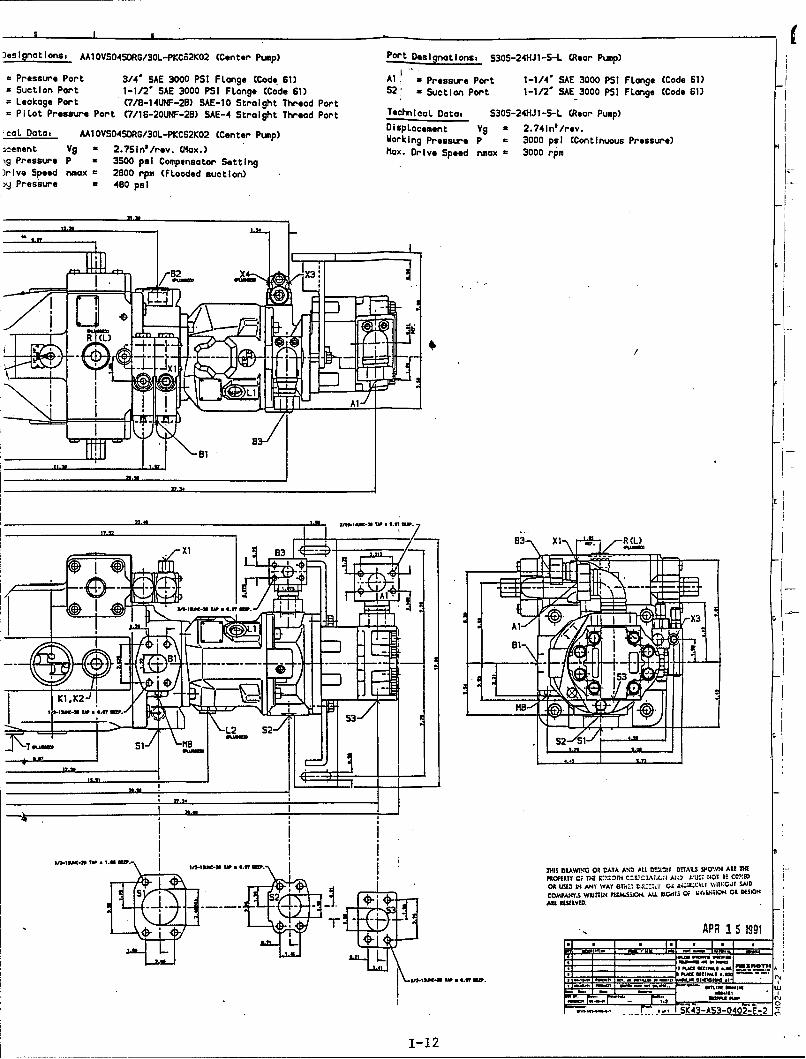
Jesignotions. M1l0VS04S0RG/30L-PKC62K02 (Center Pump) Port Dsgatos S30S-24HJ1-5-L (Rear Pump)
- Pressure Port 3/4' SAE 3000 PSI R~ange (Code 61) Al =Pressure Port 1-1/4' SAE 3000 PSI FLange (Code 61)x Suction Pont 1-1/2' SAE 3000 PSI R~ange (Code 61) S2:* Suction Port 1-1/2' SAE 3000 PSI FLange (Code 61)
=Leakage Port C7/8-I4UNF-2B) SAE-10 Straight Thread Port- P1 Lot Pressure Port (7/16-2OUNF-28) SAE-4 Straight Thread PortTehiaDt: S3 -4ilSL(erPup'caL Data, AMl0VS04SDRG/30L-PKC62K02 (Center Pump) DispLacement Vg a 2.74in*/rev.
Wdorking Pressure P a 3000 psi (Continuous Pressure)3cement V9 - 2.7Sinl/rev. (Mlax.) hex. Drive Speed nmax a 3000 rpm19 Pressure P a 3500 psi Compensator Setting)rive Speed nmax a 2800 rpm (Fooded suction)
ly Pressure 480 psi
Xl 53
X1 8'
tflt~i.NYN il-taCN Tt .97. Dis RA~NGOR AT AN.IALLG!IG~ DAIS 14OTJARAli
PIOEP Y , li £'L~l ~ C.I Z. ,u~ :/-X3 co:l
sm- S3 inbtnt~
L2 S2* *IUG
T\_T l_/ h1S-12
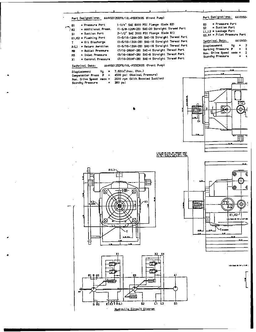
I 2 I I l I
Port Desiglnatlons AA4VS012S0FR/tOL-PSD63KO5 (Front Pump) Port Deslgnatlons, AAIOyS0,
eI ='Pressure Port 1-1/4' SAE 6000 PSI FLange (Code 62) 83 = Pressure Port
0e2 a Additional Press. (1-S/8-12UN-20) SAE-20 Straight Thread Port S2 a Suction Port
Si = Suction Port 2-1/2° SAE 3000 PSI FLange (Code 61) LlL2 = Leakage Port
K1,K2 = Flushing Port (1-S/16-12UN-28) SAE-16 Straight Thread Port X3,X4 x PiLot Pressure Port
T = OIL Discharge (1-5/16-12UN-28) SAE-16 Straight Thread Port TechnicaL Data, AAIOVSO,
R(L) U Return Aeration (1-5/16-12UN-28) SAE-16 Straight Thread Port DispLacement Vg a 2
MB a OutLet Pressure (7/16-20UNF-2B) SAE-4 Straight Thread Port Working Pressure P . 3
1S = InLet Pressure (9/16-18UNF-28) SAE-6 Straight Thread Port Max. Drive Speed nmax = 2
X1 = Control Pressure (7/16-20UNF-28) SAE-4 Straight Thread Port Standby Pressure a 4
Technical Data: AA4VS0125DFR/1OL-PSD63KO5 (Front Pump)
DispLacement Vg = 7.601n'/rev. (Max.)
Compensator Press P = 4500 psi (Nominal Pressure)
Max. Drive Speed nsax = 2600 rpm (With Boosted Suction)
Standby Pressure = 380 psi
I: TUT. 3UPLIK O S Tit . -rM im O
I x2 x4
Ii-.--I
Iludrou~li Circuit Dloar$m
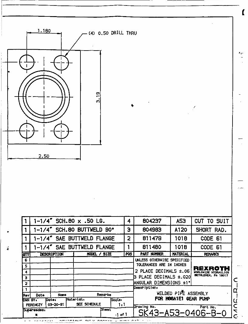
(4) 0.50 DRILL THRU
2.50
1 1-11/4 SCH.80 x .50 LG. 4 804237 A53 CUT TO SUIT
1 1-1/4' SCH.80 BUTTWELD 90° 3 804983 A120 SHORT RAD.
1 1-1/4' SAE BUTTWELD FLANGE 2 811479 1018 CODE 61
1 1-1/4' SAE BUTTWELD FLANGE 1 811480 1018 CODE 61QTY DESCRIPTION IODEL / SIZE P06 PART NUUER MATERIAL MARKS
6 UNLESS OTHERWISE SPECIFIED5 TOLERANCES ARE IN INCHES RDXROTH4 2 PLACE DECIMALS +.06 wo~wto wm•.,e
3 3 PLACE DECIMALS *.020 1I.•f11, PA 10017
2 ANGULAR DIMENSIONS :El _ __"
1 DesopiptIon,
Rev Date Name Rem-ks WELDED PI FP ASSEMBLY 1l
DN iBY, ate trlaL, oaLo FOR "IMAIEl EA PUMP UFERENCZY 03-20-91 SEE SCHEDULE 1 I I1 raw ln No. Part No. C
U 1 heat NZ_______________________des 'lof 1 5K43-A53-0406-B-Q 0 ,
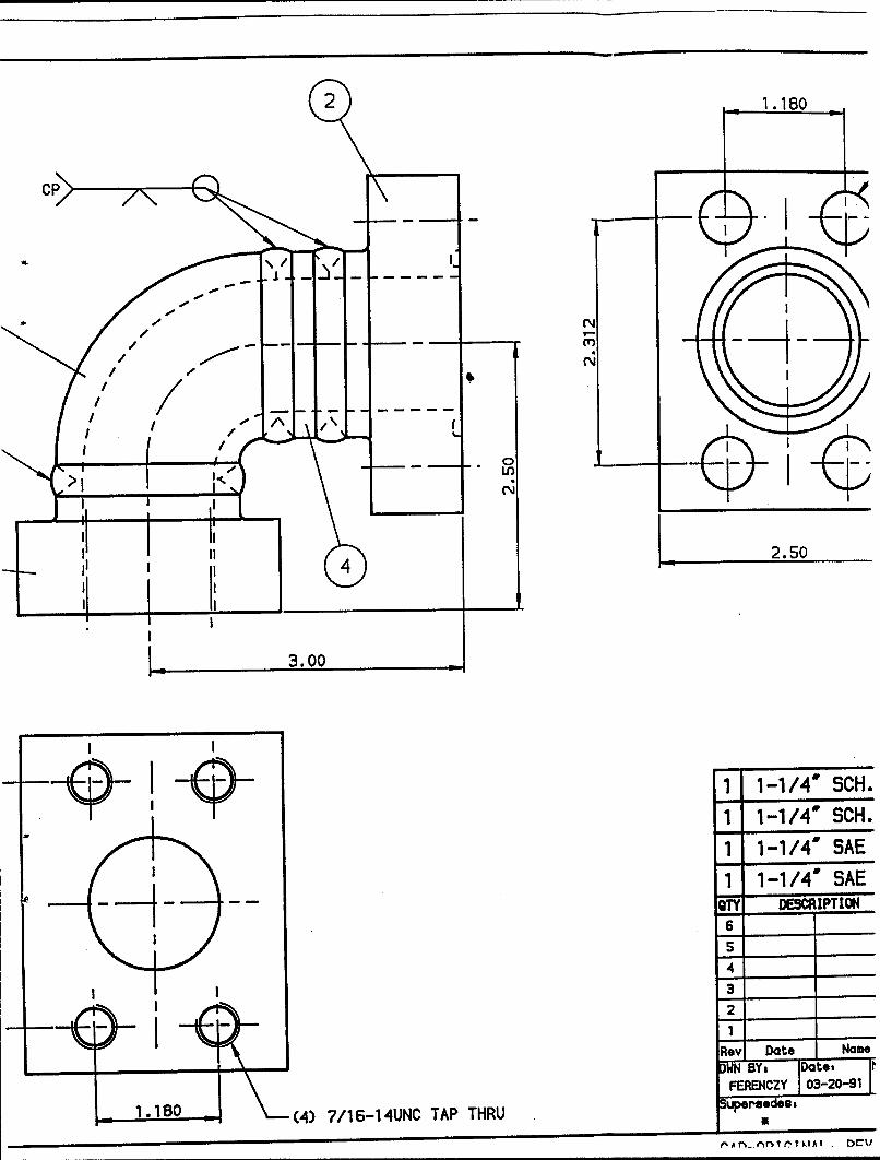
2 1.180
I-\
> Nn
c
NN
2.50
3.00
1 1-1/4' SCH.1 1-1/4' SCH.
1 1-1/4' SAE1-1 /4' SAE
oT I IPTION
--4-I _ -j t I " S
s
4
I 2
- I• 3.00___
II _
RvI Date Name: •~ e Date'I Nm
FERENCZY 03-20-911= .180 _ (4) 7/16-14UNC TAP THRU e
e'Ar_ ''tlt._TdkAI Df1t
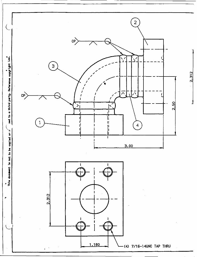
CPT
Lon
3.00
a~
S*8 4 /61UCTPTR
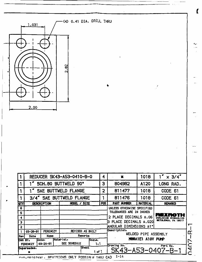
(4) 0.41 DIA. DRILL THRU
2.00
1 REDUCER SK43-AS3-0410-B-0 4 _ 1018 1' x 3/4'
1' SCH,80 BUTTWELD 90e 3 804982 A120 LONG RAD.
1' SAE BUTTWELD FLANGE 2 811477 1018 CODE 61
1 3/4' SAE BUTTWELD FLANGE 1 811476 1018 CODE 61f'Y DESCRIPTION "MEL / SIZE POS PART NUItER MATERIAL REMIAIS
6 UNLESS OTHERWISE SPECIFIED5 TOLERANCES ARE IN INCHES I xn*rH
4 2 PLACE DECIMALS 1.06 woRwDU wm.:e
3 3 PLACE DECIMALS 1.020 B M PA 18017
2 ANGULAR DIMENSIONS +I" _--1 03-28-91 FERENCZY REVISED AS BUILT DosopIptlons
Rev Date Name Remarks WELDED PIPE ASSEMBLYDWN BY, Date, Mater aL, SoOIes MBBAIE1 A1OV PUMP
FERENCZY 03-20-91 SEE SCHEDULE Drawlng No. Part No. Cm o~de s, M oe t" '1_of 1 SK43-A.53-0407-B-
nAn-n0TrTMA. PFVTSITOS ONLY POSSIRI P THRU CAD 1-14
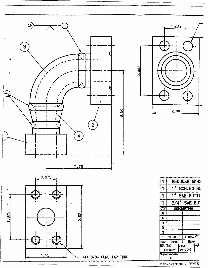
C 1 .031
3N
Ln 2.00
i2
I: I
2.75
875.. 1 REDUCER SK4%t
*1 1' SCH.8Q BL1 1' SAE BUMT
1 3/4' SAE BU1OY DESMRIPTION
6 _
3 1
1 03-28-91 FERENCZY
4<--Fl-
Rev Date NameDWN BYs Dte Mat
"FERENCZY 03-20-91
' \5(4) 3/816UNC TAP THRU w
_ __________ •i ,TI * , "PFVIS
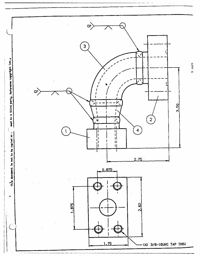
I CC
'00'
II
fb
II
CC
A)n
2.75
0. 875
LL
2.5[ ý /-1UCTPTR
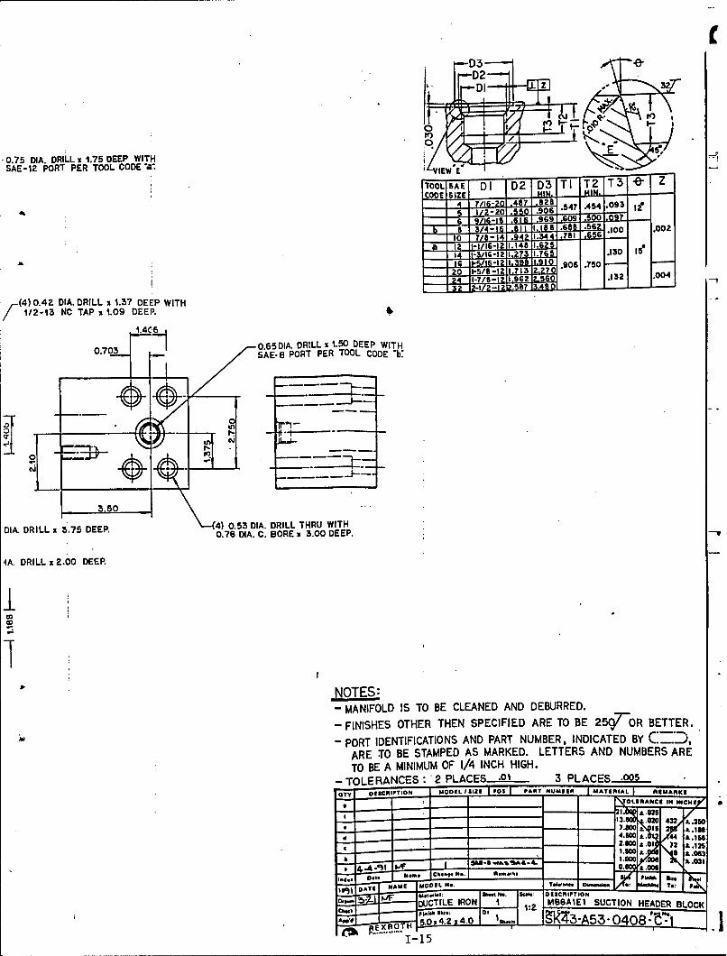
C-iT
0.75 DIA. DQRI LL x 1.75 DEEP WITHSAE-iZ PRT PER TOOL CODE'&*
TOOL SAE DI D 2 D63 TI T2 T3
(4)0~~ 4/1-2 DIA DRIL 11.28EEWT[ 1/m1 NC5 TAP 54 1.09 DEEP.
07038 0.65 DIA. DRILL .00DEPIT
~~~(4) 0.53 DIA. DRILL THR37UEE WITH
D112-1 DRIL TA.5EP 0.7 D.A. C.E BOR 1 .0 EP
0.7A. DRILL6 .- 06DA DR.00 DEEPEE WT
3.5
- MANIFOLD IS TO BE CLEANED AND DEBURRED.
- FINISHES OTHER THEN SPECIFIED ARE TO BE 25(ý7 -oR BETTER.
-PORT IDENTIFICATIONS AND PART NUMBER, INDICATED BY ".=,ARE TO BE STAMPED AS MARKED. LETTERS AND NUMBERS ARETO BE A MINIMUM OF 1/4 INCH HIGH.
- TOLERANCES: *2 PLACES .01 3 PLACES .005
IOtY O9SICRITION MODEL I SIZE FO Po ART NUMBERE MATERIAL RI AARKS
21. A.0265
13.2 .020) 432 1±210
_________2.0 A ±.01 72 &.125b1.000 .0 .031
UNN.;kM. DESCRIPTIONWUCTILE IRON I M88AIEi SUCTION HEADER BLOCK
ROTH~I ,.~24 I" i
Oa -11
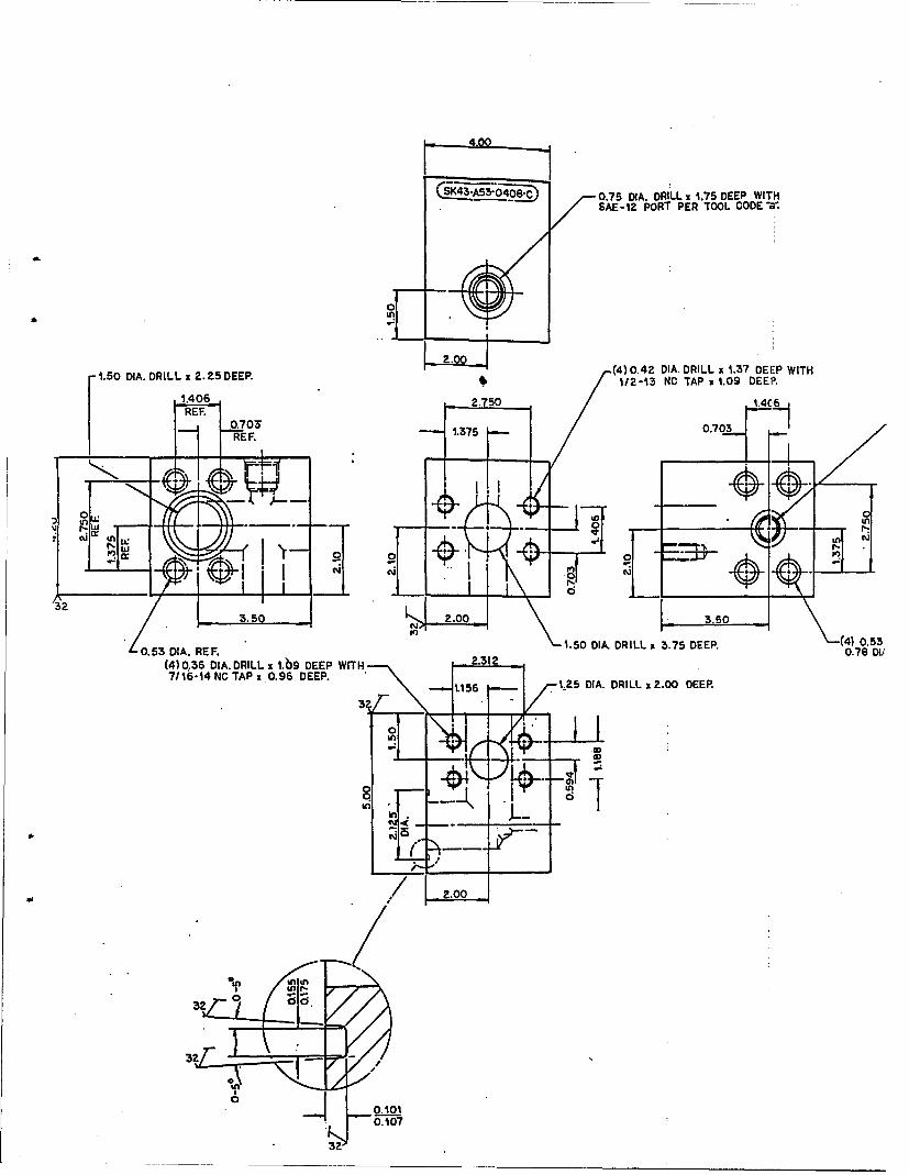
IsK43."A-3.Ooe -) 0-.0,75 DIA. DRILL x,1.75 DEEP WITHSAE-12 PORT PER TOOL CODE-al
1L(4)0.42 DIA. DRILL 1 1.37 DEEP WITH
D1/2-`13 NC TAP x 1.09 DEEP.
1.406 2.750 .4C .REF. 0.5
-R 1.375 - 0.7 3.3F___ ~~REF. -1~-3.u 2.0 3.50:0
3D51.50 OIA. DRILL x 3.75 DEER. (4) 0.53
0.53 DIA. REF. 0.78 DU'(4) 0.36 DIA. DRILLi 1.09 DEEP WITH 2.3127/16-14 NC TAP x 0.96 DEEP. 15 1.25 DIA. DRILL x 2.00 DEEP.
00
32
=n -inI - . -
;/ -_ 00_
M -
-- ,o- -32Z
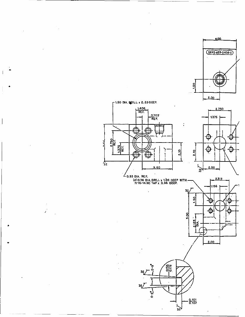
CSK43"As3-0408"c•
L10 DIA. (WLL x .25 DEEP.I1.406 2.750IDAREF.
I0,705 1.375
_RE F.
ei r'W n
3 2•
323.50 2.00
0.53 DIA. REF.(4) 0.36 DIA. DRILL 1 0.9 DEEP WITH 2.3127/16-14 NC TAPx.0.96 DEEP.
3 ?p
In?
32.0
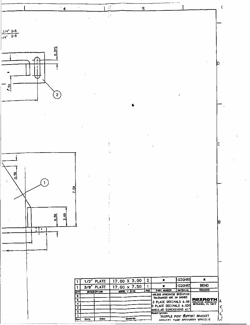
4 sI
1/4 2-5
i/4 2-5
In
--
2/
1 1/2" PLATE 17.00 X 3.00 2 1 020HRe-
0
1 3/8" PLATE 17. 00 x 7.50 1 1 020HRE€ BEND
DESCR-:IPTION ýhWL•: I "IE PO PART NUMBER MATERIAL, REJMARKS ,
sUNLESS OTHERWISE SPECIFIEDTOLERANCES ARE IN INCHES RE R T A
4 2 PLACE DECIMALS :k.06 v•ofto[C MCPAULICS
43 3 PLACE DECIMALS :1.020 wn "m PA saw ic
2ANGULAR DIMENSIONS 1"I---- -- "sc ptlio n.
1TRIPPLE PUMP !ffJPPORT BRACKETR t ý* D a t eo " ml e F to so r k l _ M Q O A I • ' l T A WL I D ¢P •r v F P Y w', t ct eI I -
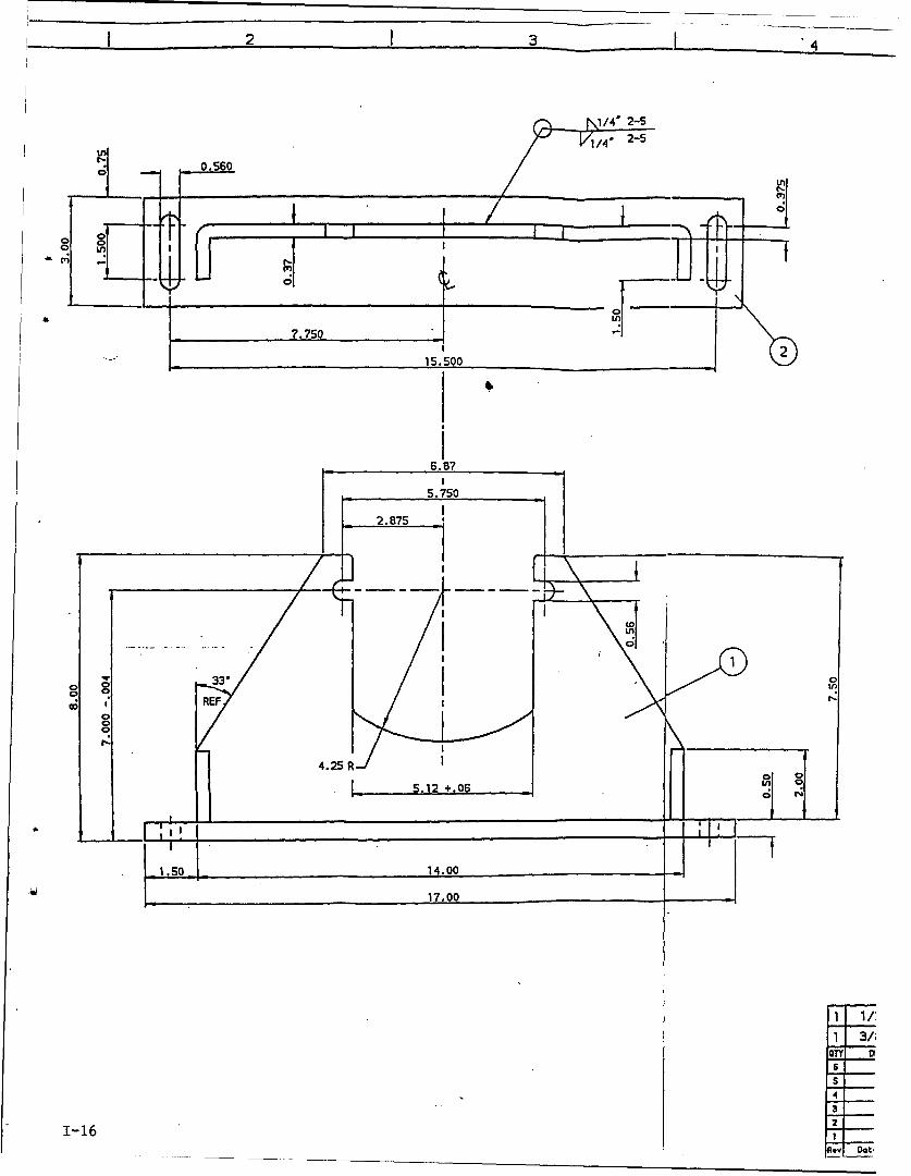
i2 I3 I 4
1/4' 2-5
/4 2-5
0.560inn
7
1050
I7.750 ,.-
5.750
2.875
, In
co /REF'•4.2S R
.-- S.12 +.06 ... .!l "
[ ON
1.50 .14.00
17.00
" ' 3/',
OTY D61
4
321-16 1
LOY Do,.
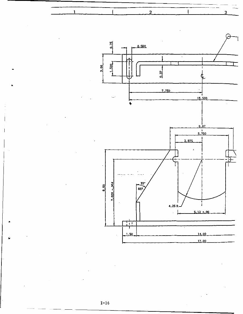
1I 2 I 3
0.560
o g"-I I-
m gI.
7.750
15.500
6.87
5.750
2.875
S_ . 12 +.06,•o 0
4.2SR 140
17.00
1-16
"APPENDIX J
Parts List
J-1
J-2
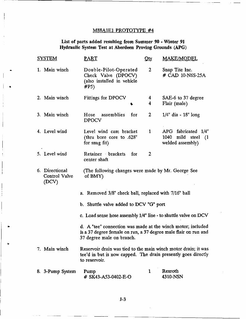
M88A1E1 PROTOTYPE #4
List of parts added resulting from Summer 90 - Winter 91Hydraulic System Test at Aberdeen Proving Grounds (APG)
SYSTEM PART _ MAKE/MODEL
1. Main winch Double-Pilot-Operated 2 Snap Tite Inc.Check Valve (DPOCV) # CAD 10-N6S-25A(also installed in vehicle#P5)
2. Main winch Fittings for DPOCV 4 SAE-6 to 37 degree& 4 Flair (male)
3. Main winch Hose assemblies for 2 1/4" dia - 18" longDPOCV
4. Level wind Level wind cam bracket 1 APG fabricated 1/4"(thru bore core to .628" 1040 mild steel (1for snug fit) welded assembly)
5. Level wind Retainer brackets for 2center shaft
6. Directional (The following changes were made by Mr. George SeeControl Valve of BMY)(DCV)
a. Removed 3/8" check ball, replaced with 7/16" ball
b. Shuttle valve added to DCV "G" port
c. Load sense hose assembly 1/4" line - to shuttle valve on DCV
d. A "tee" connection was made at the winch motor; includedis a 37 degree female on run, a 37 degree male flair on run and37 degree male on branch.
7. Main winch Reservoir drain was tied to the main winch motor drain; it wastee'd in but is now capped. The drain presently goes directlyto reservoir.
8. 3-Pump System Pump 1 Rexroth# SK43-A53-0402-E-O 4310-NSN
J-3
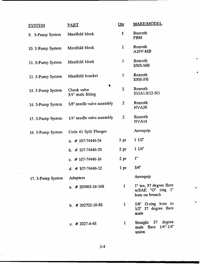
SYSTEM PART o MAKE/MODEL
9. 3-Pump System Manifold block 1 RexrothFBM
10. 3-Pump System Manifold block 1 RexrothA10V-MB
11. 3-Pump System Manifold block 1 RexrothS30S-MB
12. 3-Pump System Manifold bracket 1 RexrothS30S-FB
13. 3-Pump System Check valve 2 Rexroth3/4" male fitting S15A1.0/12-SO
14. 3-Pump System 3/8" needle valve assembly 2 RexrothNVA38
15. 3-Pump System 1/4" needle valve assembly 2 Rexroth
NVA14
16. 3-Pump System Code 61 Split Flanges Aeroquip
a. # 107-74446-24 5 pr 1 1/2"
b. # 107-74446-20 2 pr 1 1/4"
c. # 107-74446-16 2 pr 1"
d. # 107-74446-12 1 pr 3/4"
17. 3-Pump System Adapters Aeroquip
a. # 203003-16-16S 1 1" tee, 37 degree flarew/SAE "0" ring 1" "boss on branch
b. # 202702-10-8S 1 5/8" O-ring boss to1/2" 37 degree flaremale
c. # 2027-4-4S 1 Straight 37 degreemale flare 1/4"-1/4"union
J-4
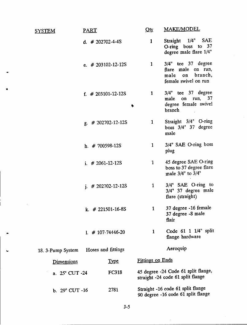
SYSTEM PART _Qy MAKE/MODEL
d. # 202702-4-4S 1 Straight 1/4" SAEO-ring boss to 37degree male flare 1/4"
e. # 203102-12-12S 1 3/4" tee 37 degreeflare male on run,male on branch,female swivel on run
f. # 203101-12-12S 1 3/4" tee 37 degreemale on run, 37
6 degree female swivelbranch
g. # 202702-12-12S 1 Straight 3/4" O-ringboss 3/4" 37 degreemale
h. # 700598-12S 1 3/4" SAE O-ring bossplug
i. # 2061-12-12S 1 45 degree SAE O-ringboss to 37 degree flaremale 3/4" to 3/4"
j. # 202702-12-12S 1 3/4" SAE O-ring to3/4" 37 degree maleflare (straight)
k. # 221501-16-8S 1 37 degree -16 female37 degree -8 maleflair
1. # 107-74446-20 1 Code 61 1 1/4" split
flange hardware
18. 3-Pump System Hoses and fittings Aeroquip
Dimensions y Fittings on Ends
a. 25" CUT -24 FC318 45 degree -24 Code 61 split flange,straight -24 code 61 split flange
b. 29" CUT -16 2781 Straight -16 code 61 split flange
90 degree -16 code 61 split flange
J-5
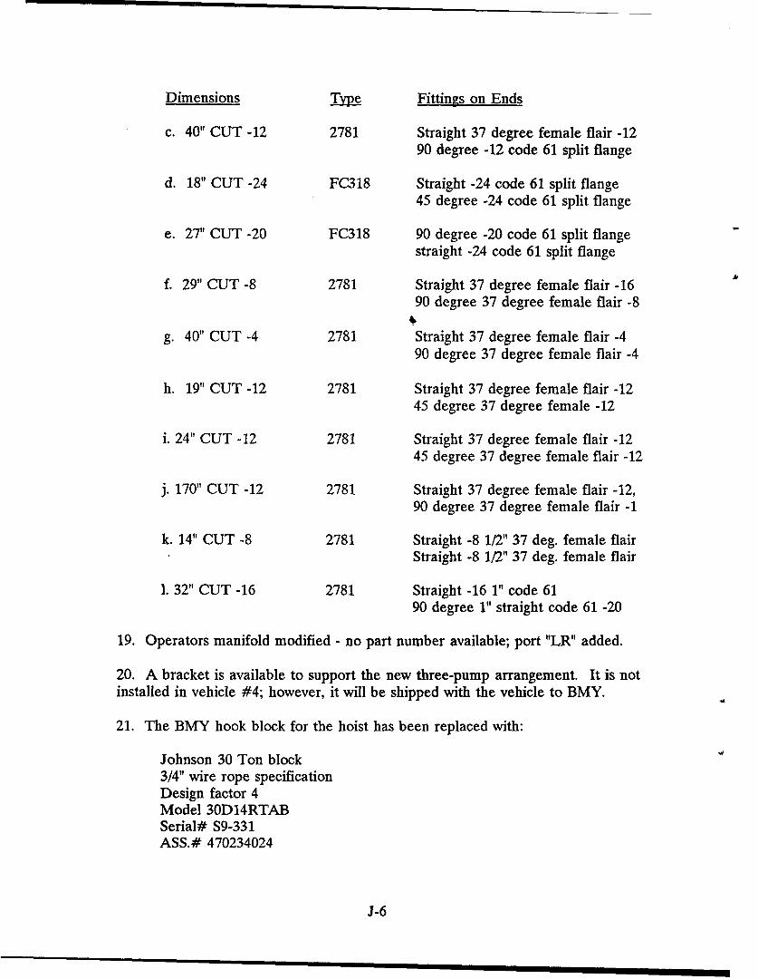
Dimensions n7y Fittings on Ends
c. 40" CUT -12 2781 Straight 37 degree female flair -1290 degree -12 code 61 split flange
d. 18" CUT -24 FC318 Straight -24 code 61 split flange45 degree -24 code 61 split flange
e. 27" CUT -20 FC318 90 degree -20 code 61 split flangestraight -24 code 61 split flange
f. 29" CUT -8 2781 Straight 37 degree female flair -1690 degree 37 degree female flair -8
g. 40" CUT -4 2781 Straight 37 degree female flair -490 degree 37 degree female flair -4
h. 19" CUT -12 2781 Straight 37 degree female flair -1245 degree 37 degree female -12
i. 24" CUT -12 2781 Straight 37 degree female flair -1245 degree 37 degree female flair -12
j. 170" CUT -12 2781 Straight 37 degree female flair -12,90 degree 37 degree female flair -1
k. 14" CUT -8 2781 Straight -8 1/2" 37 deg. female flairStraight -8 1/2" 37 deg. female flair
1. 32" CUT -16 2781 Straight -16 1" code 6190 degree 1" straight code 61 -20
19. Operators manifold modified - no part number available; port "LR" added.
20. A bracket is available to support the new three-pump arrangement. It is notinstalled in vehicle #4; however, it will be shipped with the vehicle to BMY.
21. The BMY hook block for the hoist has been replaced with:
Johnson 30 Ton block3/4" wire rope specificationDesign factor 4Model 30D14RTABSerial# S9-331ASS.# 470234024
J-6
APPENDIX K
Oil Cooler
K-1
K-2
APPENDIX K
M88A1E1 HYDRAULIC OIL TEMPERATURE ANALYSIS
Present and past testing of the M88AIE1 hydraulic systems has shown thattypical work cycles cannot be completed without the oil temperature exceedingmaximum allowable levels for safe operation.
To eliminate the problem, an oil cooler is required. A system temperatureanalysis was made to understand both how and where the temperatures were beingaffected. Upon analyzing the results, it was possible to arrive at a preliminary sizingfor a cooler. Maximum temperatures were used to arrive at the cooler sizing.
The temperature and oil cooler analysis contain the following information:
I. System temperature analysis - a theoretical calculation of final systemtemperatures.
II. Determination of maximum hydraulic oil heat gain.
III. Preliminary cooler selection.
IV. Theoretical calculation of oil cooler sizing.
K-3
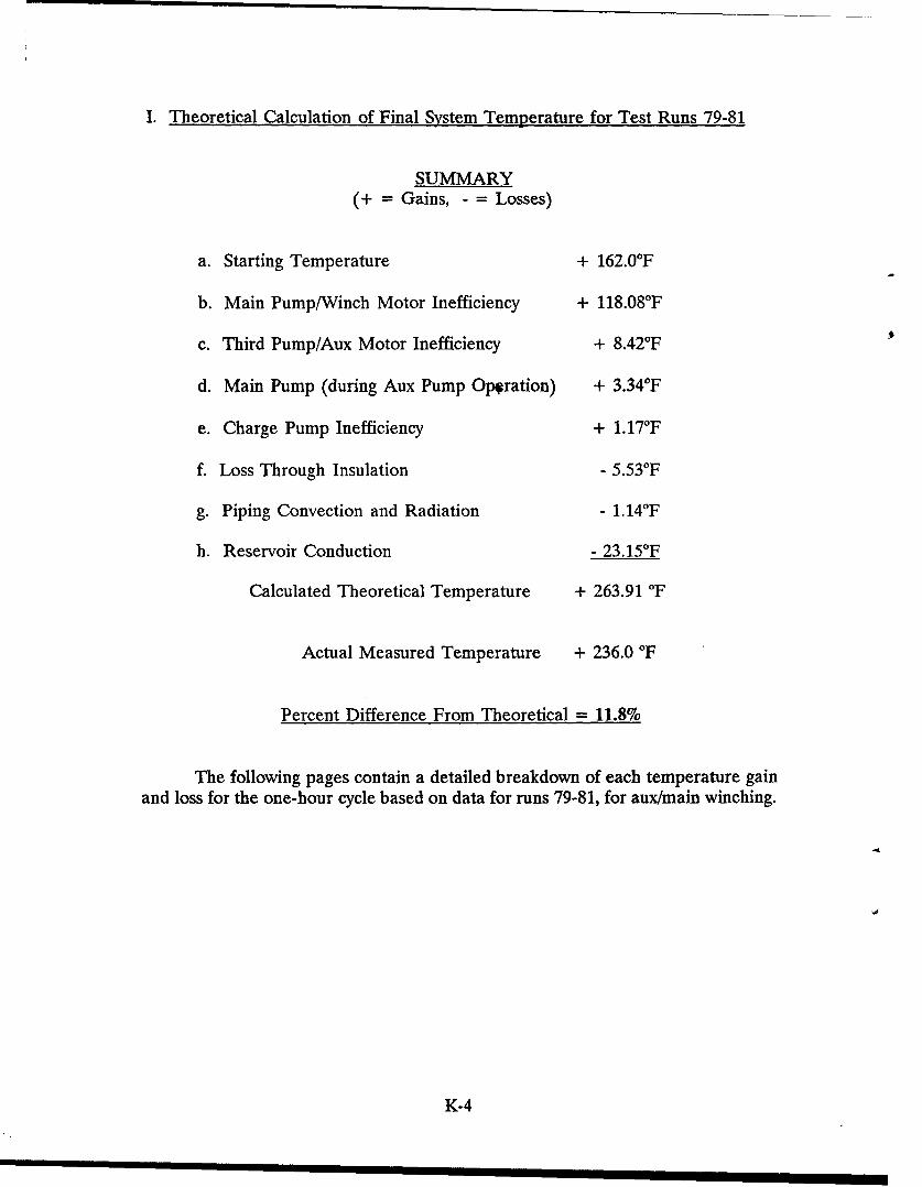
I. Theoretical Calculation of Final System Temperature for Test Runs 79-81
SUMMARY(+ = Gains, - = Losses)
a. Starting Temperature + 162.0°F
b. Main Pump/Winch Motor Inefficiency + 118.08OF
c. Third Pump/Aux Motor Inefficiency + 8.420F
d. Main Pump (during Aux Pump Op.ration) + 3.34°F
e. Charge Pump Inefficiency + 1.17 0F
f. Loss Through Insulation - 5.53°F
g. Piping Convection and Radiation - 1.140F
h. Reservoir Conduction - 23.15°F
Calculated Theoretical Temperature + 263.91 OF
Actual Measured Temperature + 236.0 OF
Percent Difference From Theoretical = 11.8%
The following pages contain a detailed breakdown of each temperature gainand loss for the one-hour cycle based on data for runs 79-81, for aux/main winching.
K-4
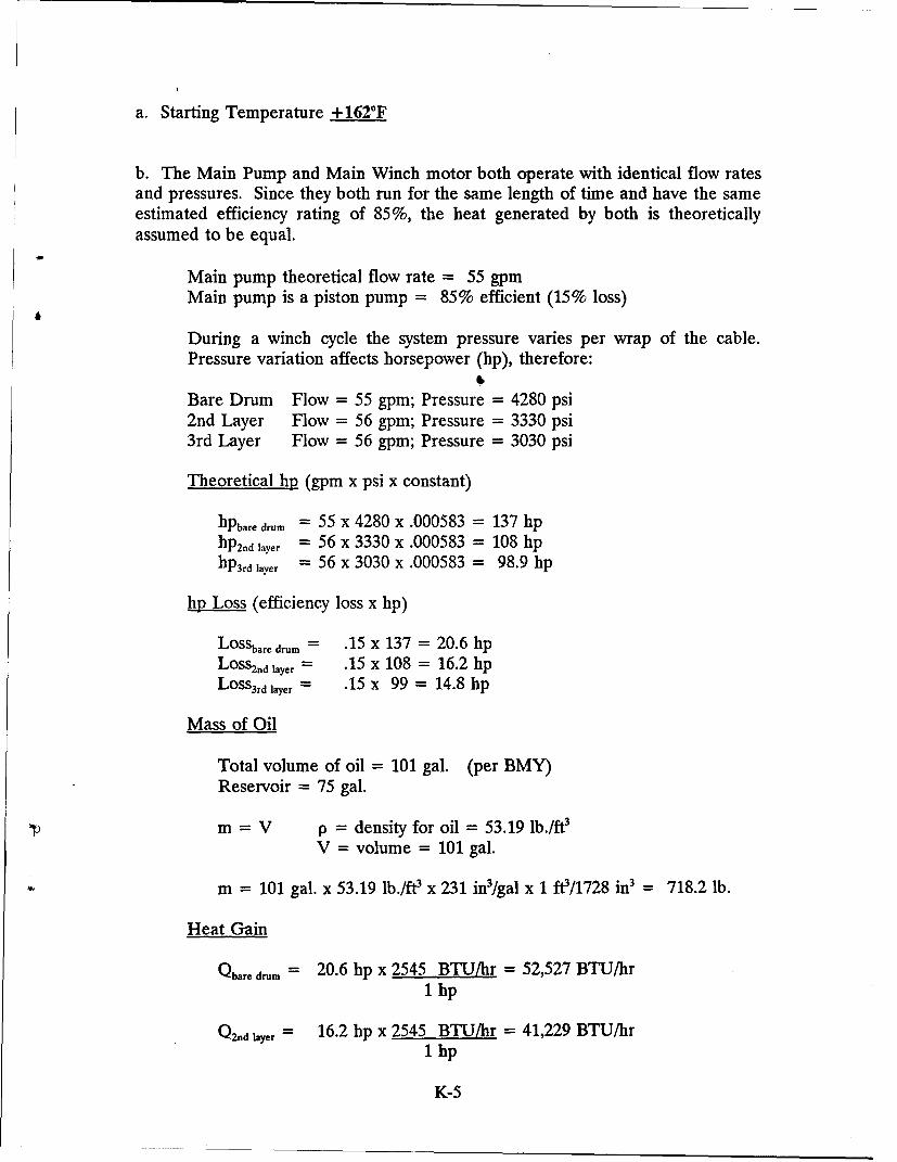
a. Starting Temperature + 162°F
b. The Main Pump and Main Winch motor both operate with identical flow ratesand pressures. Since they both run for the same length of time and have the sameestimated efficiency rating of 85%, the heat generated by both is theoreticallyassumed to be equal.
Main pump theoretical flow rate = 55 gpmMain pump is a piston pump = 85% efficient (15% loss)
During a winch cycle the system pressure varies per wrap of the cable.Pressure variation affects horsepower (hp), therefore:
Bare Drum Flow = 55 gpm; Pressure = 4280 psi2nd Layer Flow = 56 gpm; Pressure = 3330 psi3rd Layer Flow = 56 gpm; Pressure = 3030 psi
Theoretical hp (gpm x psi x constant)
hpbare drum = 55 x 4280 x .000583 = 137 hphp2.d layer = 56 x 3330 x .000583 = 108 hphP3rd layer = 56 x 3030 x .000583 = 98.9 hp
.hp Loss (efficiency loss x hp)
LOSsbare drum = .15 x 137 = 20.6 hpLoss2Dd layer = .15 x 108 = 16.2 hpLosS3rd layer = .15 X 99 = 14.8 hp
Mass of Oil
Total volume of oil = 101 gal. (per BMY)Reservoir = 75 gal.
m = V p = density for oil = 53.19 lb./WV = volume = 101 gal.
m = 101 gal. x 53.19 lb./ft x 231 in 3/gal x 1 f0/1728 in3 = 718.2 lb.
Heat Gain
Qbare drum = 20.6 hp x 2545 BTU/hr = 52,527 BTU/hr1 hp
Q2od layr = 16.2 hp x 2545 BTU/hr = 41,229 BTU/hr1 hp
K-5
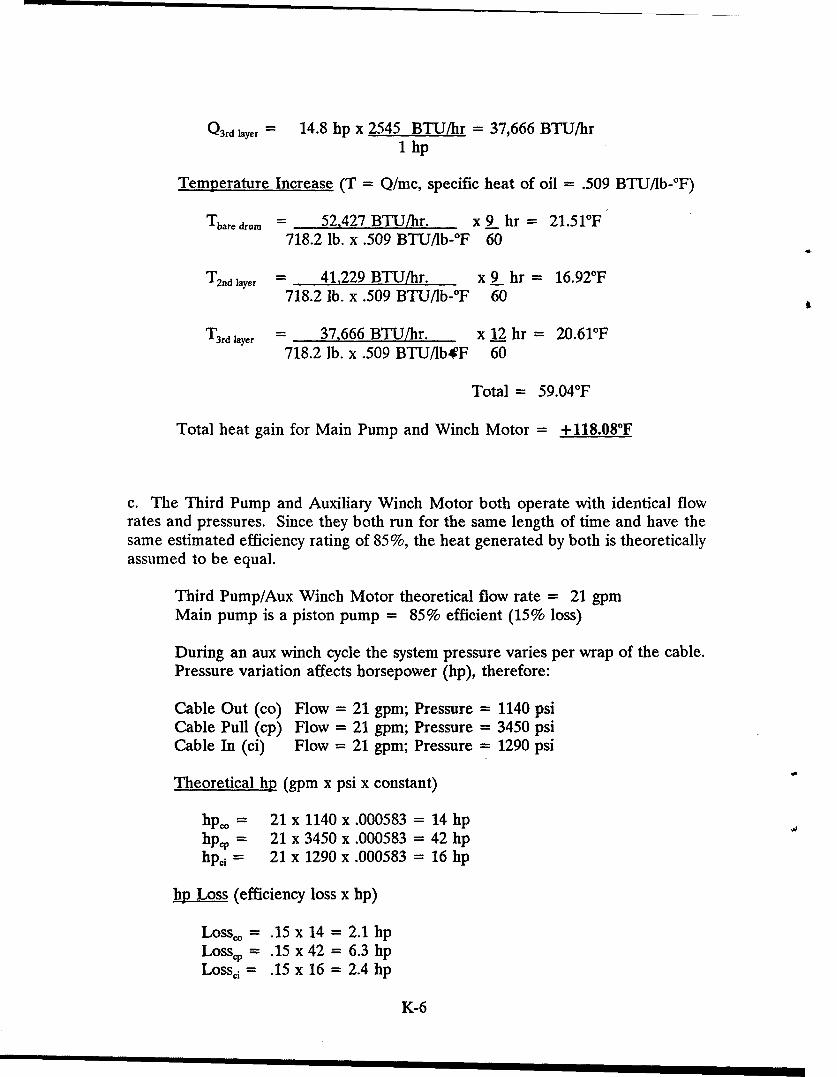
Q3rd layer = 14.8 hp x 2545 BTU/hr = 37,666 BTU/hr
1 hp
Temperature Increase (T = Q/mc, specific heat of oil = .509 BTU/lb-°F)
Tbare drum = 52,427 BTU/hr. x 9 hr = 21.5 1°F718.2 lb. x .509 BTU/Ib-°F 60
T 2nd layer = 41,229 BTU/hr. x 9 hr = 16.92°F718.2 lb. x .509 BTU/lb-°F 60
T 3rd layer = 37,666 BTU/hr. x 12 hr = 20.61°F718.2 lb. x .509 BTU/lb*F 60
Total = 59.04°F
Total heat gain for Main Pump and Winch Motor = + 118.08'F
c. The Third Pump and Auxiliary Winch Motor both operate with identical flowrates and pressures. Since they both run for the same length of time and have thesame estimated efficiency rating of 85%, the heat generated by both is theoreticallyassumed to be equal.
Third Pump/Aux Winch Motor theoretical flow rate = 21 gpmMain pump is a piston pump = 85% efficient (15% loss)
During an aux winch cycle the system pressure varies per wrap of the cable.Pressure variation affects horsepower (hp), therefore:
Cable Out (co) Flow = 21 gpm; Pressure = 1140 psiCable Pull (cp) Flow = 21 gpm; Pressure = 3450 psiCable In (ci) Flow = 21 gpm; Pressure = 1290 psi
Theoretical hp (gpm x psi x constant)
hpo = 21 x 1140 x .000583 = 14 hphpC, = 21 x 3450 x .000583 = 42 hphpc, = 21 x 1290 x .000583 = 16 hp
hp Loss (efficiency loss x hp)
Lossco = .15 x 14 = 2.1 hpLosscp = .15 x 42 = 6.3 hpLossci = .15 x 16 = 2.4 hp
K-6
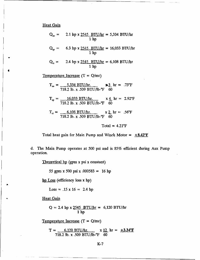
Heat Gain
QC = 2.1 hp x 2545 BTU/hr = 5,334 BTU/hr1 hp
QC, = 6.3 lip x 2545 BTU/hr = 16,033 BTU/hr1 hp
Qcj = 2.4 hp x 2545 BTU/hr = 6,108 BTU/hr1 hp
Temperature Increase (T = Q/mc)
T. = 5,334 BTU/hr. *3_ hr = .73°F718.2 lb. x .509 BTU/lb-°F 60
Trp = 16,033 BTU/hr. x 4 hr = 2.92°F718.2 lb. x .509 BTU/lb-°F 60
T= 6,108 BTU/hr. x 2 hr = .56°F718.2 lb. x .509 BTUI1b-°F 60
Total = 4.21°F
Total heat gain for Main Pump and Winch Motor = +8.42°F
d. The Main Pump operates at 500 psi and is 85% efficient during Aux Pump
operation.
Theoretical hp (gpm x psi x constant)
55 gpm x 500 psi x .000583 = 16 hp
hp Loss (efficiency loss x hp)
Loss= .15x16= 2.4lhp
Heat Gain
Q = 2.4 hp x 2545 BTU/hr = 6,120 BTU/hr1 hp
Temperature Increase (T = Q/mc)
T = 6,120 BTU/hr. x 12 hr = +3.34°F718.2 lb. x .509 BTU/Ib-*F 60
K-7
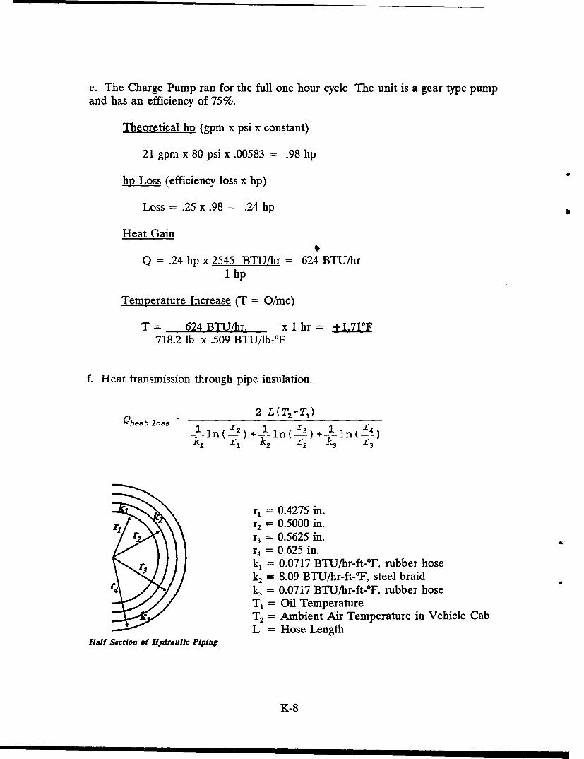
e. The Charge Pump ran for the full one hour cycle The unit is a gear type pump
and has an efficiency of 75%.
Theoretical hp (gpm x psi x constant)
21 gpm x 80 psi x .00583 = .98 hp
hp Loss (efficiency loss x hp)
Loss = .25 x .98 = .24 hp
Heat Gain
Q = .24 hp x 2545 BTU/hr = 624 BTU/hr1 hp
Temperature Increase (T = Q/mc)
T = 624 BTU/hr. x 1 hr = +1.71°F718.2 lb. x .509 BTU/Ib-°F
f. Heat transmission through pipe insulation.
2 L(T 2 -TI)Qheat loss =.~n~.)+lnI)+1(~1in(!-r-2 )+ 1 1n (.:E23--) +---i1n ( r--4)3 3
171 k2 -r2 kc3 -r3
r, = 0.4275 in.r2 = 0.5000 in.r3 = 0.5625 in.
=r 0.625 in.k, = 0.0717 BTU/hr-ft-°F, rubber hosek 2 = 8.09 BTU/hr-ft-°F, steel braid
rD .,/k 3 = 0.0717 BTU/hr-ft-°F, rubber hoseT= Oil TemperatureT 2 = Ambient Air Temperature in Vehicle CabL = Hose Length
Half Section of Hydraulic Piping
K-8
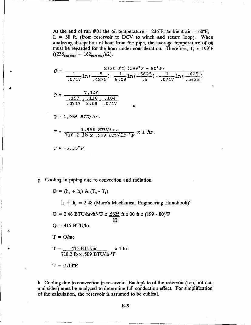
At the end of run #81 the oil temperature = 236°F, ambient air = 60'F,L = 30 ft. (from reservoir to DCV to winch and return loop). Whenanalyzing dissipation of heat from the pipe, the average temperature of oilmust be regarded for the hour under consideration. Therefore, T2 = 199°F(( 2 3 6 endtemp + 162ta.r temp)/ 2 ).
2 (30 ft) (199 0 F - 80 0 F)1 n( .5 ) 1 ln( '5625)+ 1 in( "625
.0717 .4275 8.09 .5 .0717 .5625
0_- ~ 7,140.157 + .118+ .104
.0717 8.09 .0717
Q = 1, 956 BTU/hr.
T = 1,956 BTU/hr. x 1 hr.718.2 lb x .509 BTU/Ilb-OF
T = -5.35 0 F
g. Cooling in piping due to convection and radiation.
Q = (h. + hr) A (T2 - T1)
hc + hr = 2.48 (Marc's Mechanical Engineering Handbook)a
Q = 2.48 BTU/hr-ft2 -°F x .5625 ft x 30 ft x (199 - 80)°F12
Q = 415 BTU/hr.
T = Q/mc
T = 415 BTU/hr x 1 hr.718.2 lb x .509 BTU/lb-°F
T = -1.14'F
h. Cooling due to convection in reservoir. Each plate of the reservoir (top, bottom,and sides) must be analyzed to determine full conduction effect. For simplificationof the calculation, the reservoir is assumed to be cubical.
K-9
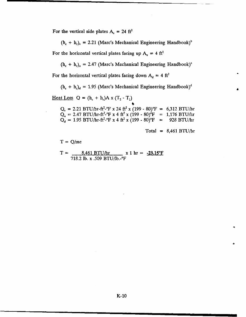
For the vertical side plates A, = 24 ft2
(he + hr)v = 2.21 (Marc's Mechanical Engineering Handbook)b
For the horizontal vertical plates facing up A. = 4 ft2
(h, + hr)u = 2.47 (Marc's Mechanical Engineering Handbook)c
For the horizontal vertical plates facing down Ad = 4 ft2
(he + h,)d = 1.95 (Marc's Mechanical Engineering Handbook)d
Heat Loss Q = (h, + h1)A x (T2 - T1)
Q, = 2.21 BTU/hr-ft2-°F x 24 ft2 x (199 - 80)°F = 6,312 BTU/hrQu = 2.47 BTU/hr-ft2 -°F x 4 ft2 x (199 - 80)*F = 1,176 BTU/hrQd = 1.95 BTU/hr-ft2-OF x 4 ft2 x (199 - 80)°F = 928 BTU/hr
Total = 8,461 BTU/hr
T = Q/mc
T = 8,461 BTU/hr x 1 hr = -23.15'F718.2 lb. x .509 BTU/lb.-°F
K-10
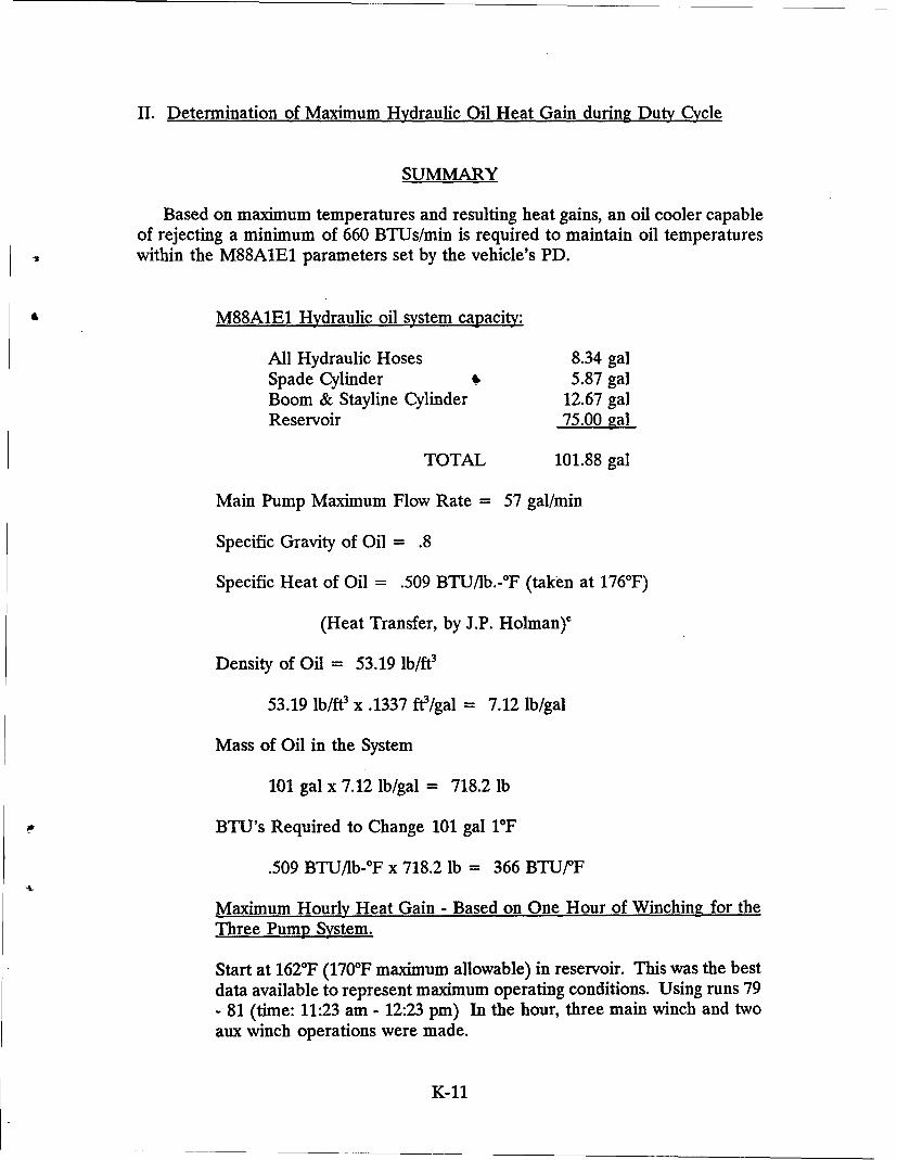
II. Determination of Maximum Hydraulic Oil Heat Gain during Duty Cycle
SUMMARY
Based on maximum temperatures and resulting heat gains, an oil cooler capableof rejecting a minimum of 660 BTUs/min is required to maintain oil temperatureswithin the M88A1E1 parameters set by the vehicle's PD.
M88A1E1 Hydraulic oil system capacity:
All Hydraulic Hoses 8.34 galSpade Cylinder .0 5.87 galBoom & Stayline Cylinder 12.67 galReservoir 75.00 gal
TOTAL 101.88 gal
Main Pump Maximum Flow Rate = 57 gal/min
Specific Gravity of Oil = .8
Specific Heat of Oil = .509 BTU/lb.-0F (taken at 176°F)
(Heat Transfer, by J.P. Holman)e
Density of Oil = 53.19 lb/ft3
53.19 lb/W x .1337 ft/gal = 7.12 lb/gal
Mass of Oil in the System
101 gal x 7.12 lb/gal = 718.2 lb
BTU's Required to Change 101 gal i°F
.509 BTU/Ib-*F x 718.2 lb = 366 BTU/F
Maximum Hourly Heat Gain - Based on One Hour of Winching for theThree Pump System.
Start at 162°F (170 0F maximum allowable) in reservoir. This was the bestdata available to represent maximum operating conditions. Using runs 79- 81 (time: 11:23 am - 12:23 pm) In the hour, three main winch and twoaux winch operations were made.
K-11
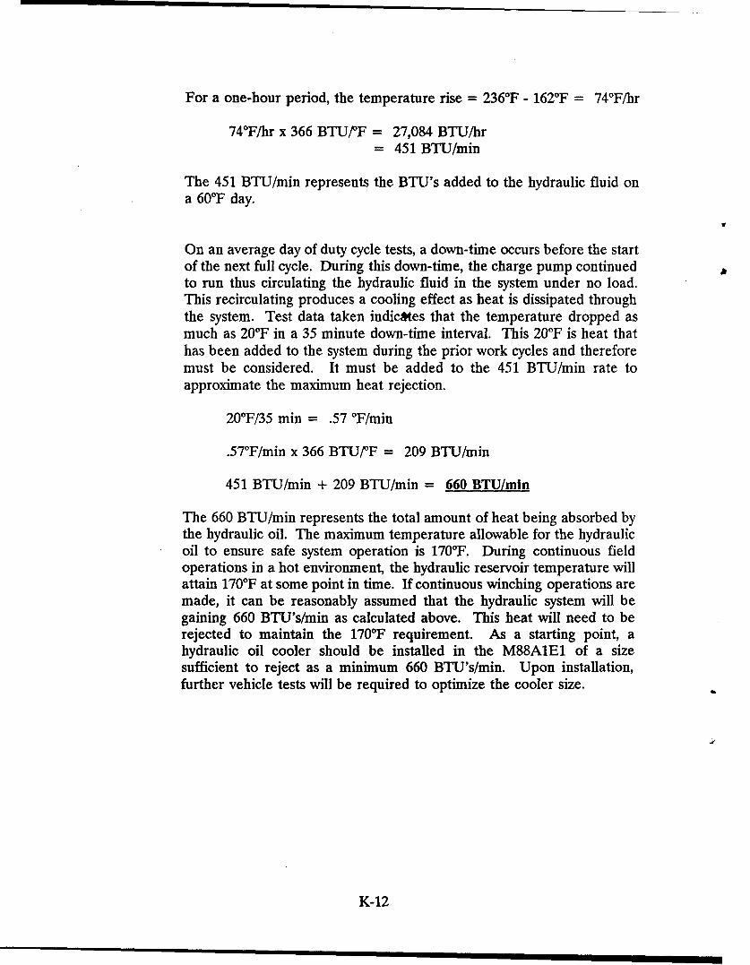
For a one-hour period, the temperature rise = 236'F - 162°F = 74°F/hr
74°F/hr x 366 BTU/PF = 27,084 BTU/hr= 451 BTU/min
The 451 BTU/min represents the BTU's added to the hydraulic fluid ona 60°F day.
On an average day of duty cycle tests, a down-time occurs before the startof the next full cycle. During this down-time, the charge pump continuedto run thus circulating the hydraulic fluid in the system under no load.This recirculating produces a cooling effect as heat is dissipated throughthe system. Test data taken indicates that the temperature dropped asmuch as 20°F in a 35 minute down-time interval. This 20'F is heat thathas been added to the system during the prior work cycles and thereforemust be considered. It must be added to the 451 BTU/min rate toapproximate the maximum heat rejection.
20'F/35 min = .57 °F/min
.57*F/min x 366 BTU/°F = 209 BTU/min
451 BTU/min + 209 BTU/min = 660 BTU/min
The 660 BTU/min represents the total amount of heat being absorbed bythe hydraulic oil. The maximum temperature allowable for the hydraulicoil to ensure safe system operation is 170°F. During continuous fieldoperations in a hot environment, the hydraulic reservoir temperature willattain 170'F at some point in time. If continuous winching operations aremade, it can be reasonably assumed that the hydraulic system will begaining 660 BTU's/min as calculated above. This heat will need to berejected to maintain the 170°F requirement. As a starting point, ahydraulic oil cooler should be installed in the M88A1E1 of a sizesufficient to reject as a minimum 660 BTU's/min. Upon installation,further vehicle tests will be required to optimize the cooler size.
K-12
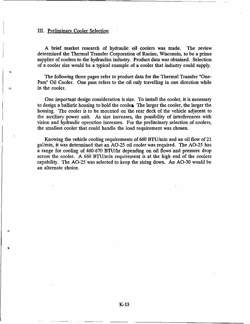
III. Preliminary Cooler Selection
A brief market research of hydraulic oil coolers was made. The reviewdetermined the Thermal Transfer Corporation of Racine, Wisconsin, to be a primesupplier of coolers to the hydraulics industry. Product data was obtained. Selectionof a cooler size would be a typical example of a cooler that industry could supply.
The following three pages refer to product data for the Thermal Transfer "One-Pass" Oil Cooler. One pass refers to the oil only travelling in one direction whilein the cooler.
One important design consideration is size. To install the cooler, it is necessaryto design a ballistic housing to hold the coole* The larger the cooler, the larger thehousing. The cooler is to be mounted on the rear deck of the vehicle adjacent tothe auxiliary power unit. As size increases, the possibility of interferences withvision and hydraulic operation increases. For the preliminary selection of coolers,the smallest cooler that could handle the load requirement was chosen.
Knowing the vehicle cooling requirements of 660 BTU/min and an oil flow of 21gal/min, it was determined that an AO-25 oil cooler was required. The AO-25 hasa range for cooling of 460-670 BTU/hr depending on oil flows and pressure dropacross the cooler. A 660 BTU/min requirement is at the high end of the coolerscapability. The AO-25 was selected to keep the sizing down. An AO-30 would bean alternate choice.
K-13
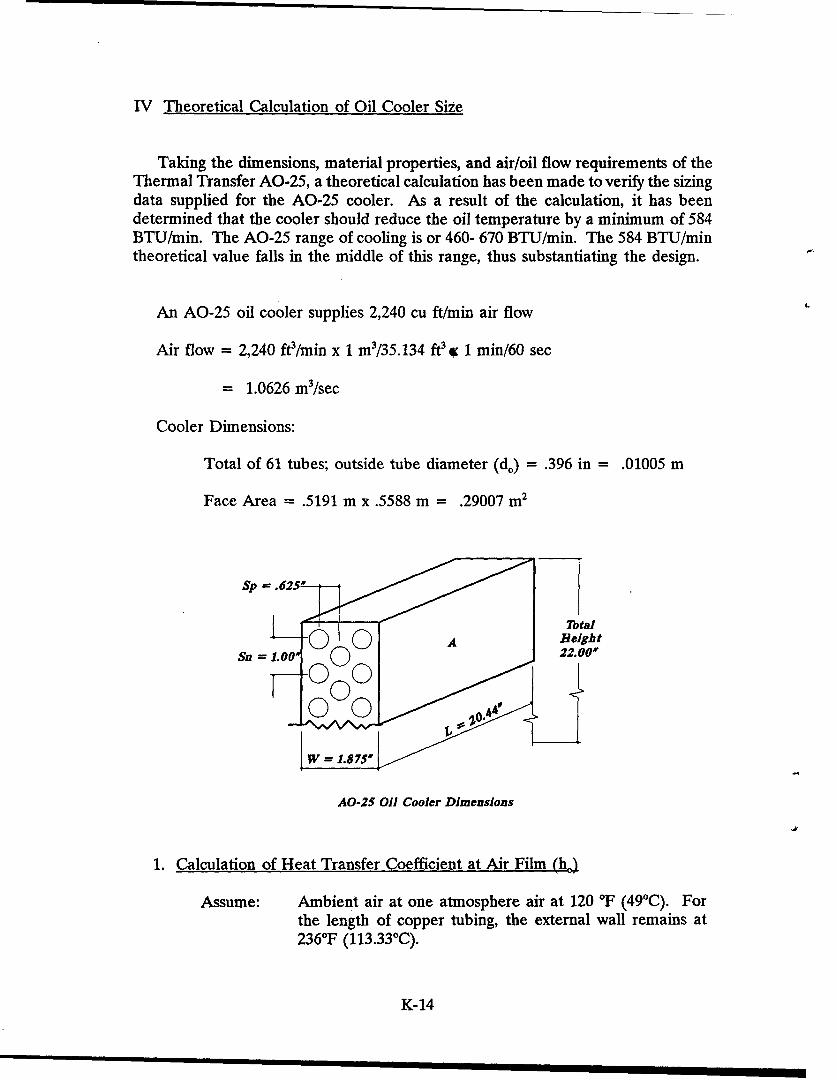
IV Theoretical Calculation of Oil Cooler Size
Taking the dimensions, material properties, and air/oil flow requirements of theThermal Transfer AO-25, a theoretical calculation has been made to verify the sizingdata supplied for the AO-25 cooler. As a result of the calculation, it has beendetermined that the cooler should reduce the oil temperature by a minimum of 584BTU/min. The AO-25 range of cooling is or 460- 670 BTU/min. The 584 BTU/mintheoretical value falls in the middle of this range, thus substantiating the design.
An AO-25 oil cooler supplies 2,240 cu ft/min air flow
Air flow = 2,240 ftW/min x 1 m3/35.134 ft3 a 1 min/60 sec
= 1.0626 m3/sec
Cooler Dimensions:
Total of 61 tubes; outside tube diameter (d.) = .396 in = .01005 m
Face Area = .5191 m x .5588 m = .29007 m2
Sp =-.625•-
S' " 7otaIL A Reight
Sn = 1.00* 22.00'
AO-25 Oil Cooler Dimensions
1. Calculation of Heat Transfer Coefficient at Air Film (he)
Assume: Ambient air at one atmosphere air at 120 *F (49'C). Forthe length of copper tubing, the external wall remains at236-F (113.33°C).
K-14
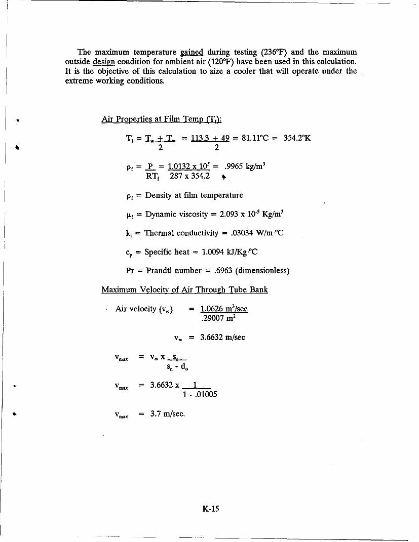
The maximum temperature gained during testing (2360F) and the maximumoutside design condition for ambient air (120°F) have been used in this calculation.It is the objective of this calculation to size a cooler that will operate under theextreme working conditions.
Air Properties at Film Temp (Tf,).
Tf = Tw+±T. = 113.3 + 49 = 81.11'C= 354.2°K•,2 2
pf = P = 1.0132 x 105= .9965 kg/m3
RTf 287 x 354.2
pf = Density at film temperature
kf = Dynamic viscosity = 2.093 x 10⁻⁵ Kg/m3
kf = Thermal conductivity = .03034 W/m PC
cp = Specific heat = 1.0094 kJ/Kg.°C
Pr = Prandtl number = .6963 (dimensionless)
Maximum Velocity of Air Through Tube Bank
Air velocity (v.) = 1.0626 m3/sec.29007 m
2
v. = 3.6632 m/sec
Vmax = V XSn - do
Vma = 3.6632x 11 - .01005
Vmax = 3.7 m/sec.
K-15
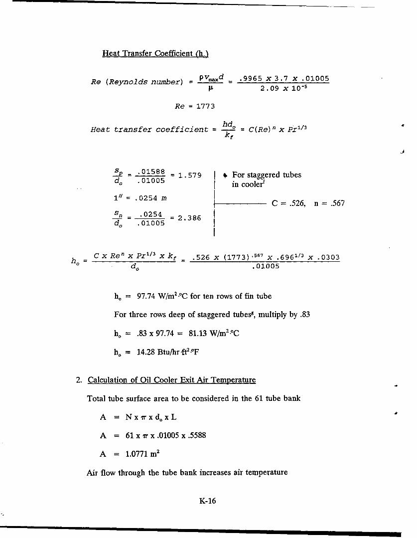
Heat Transfer Coefficient (ho)
Re (Reynolds number) = pvmaxd _ .9965 x 3.7 x .010059 2.09 X 10⁻⁵
Re = 1773
Heat transfer coefficient -hd = C(Re)n x Pr113kf
sp - .01588 - 1.579 , For staggered tubesd, .01005 in coolerf
1" =.0254 mC = .526, n=.567
Sn _.0254 -2.386
d, .01005
ho CCxRenx Pr1 /3 xkf - .526 x (1773) .567 x .6961/3 x .0303do .01005
ho = 97.74 W/m2 .OC for ten rows of fin tube
For three rows deep of staggered tubes8 , multiply by .83
ho = .83 x 97.74 = 81.13 W/m2 .oC
ho = 14.28 Btu/hr.ft2?-F
2. Calculation of Oil Cooler Exit Air Temperature
Total tube surface area to be considered in the 61 tube bank
A = Nx~rxdoxL
A = 61x"rx.01005x.5588
A = 1.0771 m2
Air flow through the tube bank increases air temperature
K-16
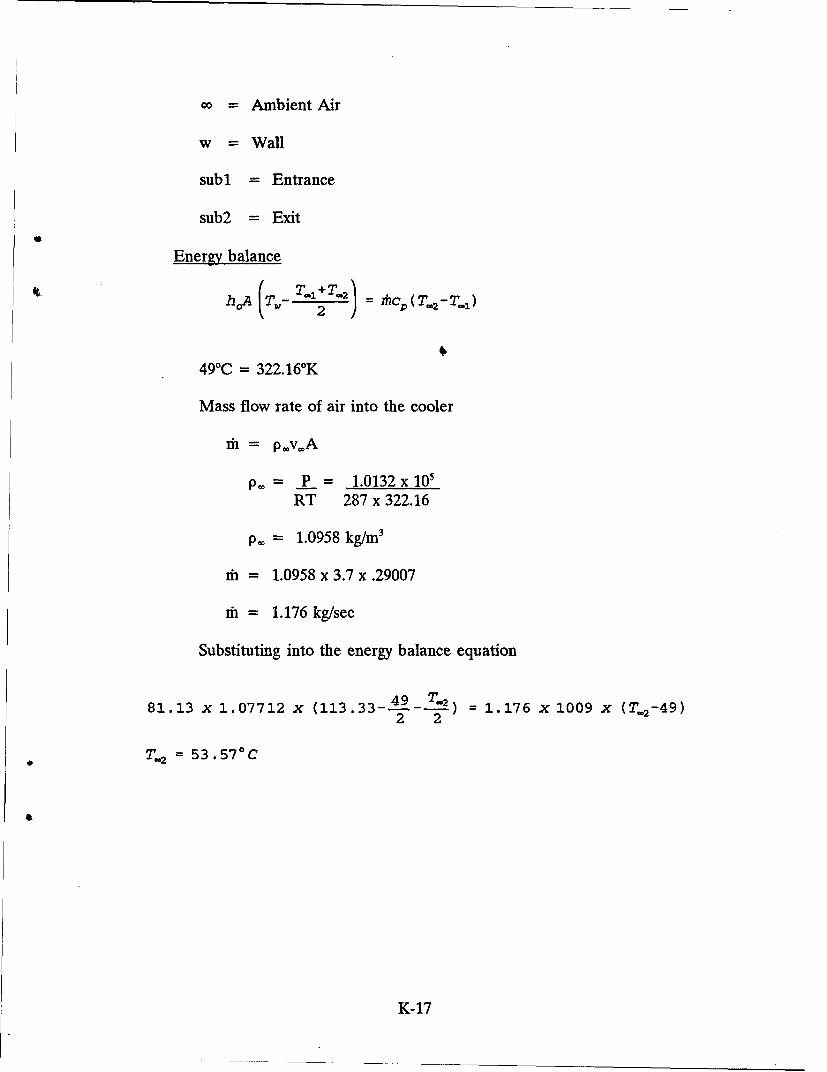
oo = Ambient Air
w = Wall
sub1 = Entrance
sub2 = Exit
Energy balance
hA (T.- T-I2T-2 ) = T nc2 (T- 2 -T-1)
49°C = 322.16'K
Mass flow rate of air into the cooler
mi = p*v*A
p. = P = 1.0132x 10'RT 287 x 322.16
p.0 = 1.0958 kg/m3
in = 1.0958 x 3.7 x .29007
di = 1.176 kg/sec
Substituting into the energy balance equation
81.13 x 1.07712 x (113.33--1-99-T-2) = 1.176 x 1009 x (T. 2 -49)2 2
T.2 = 53.57-C
K-17
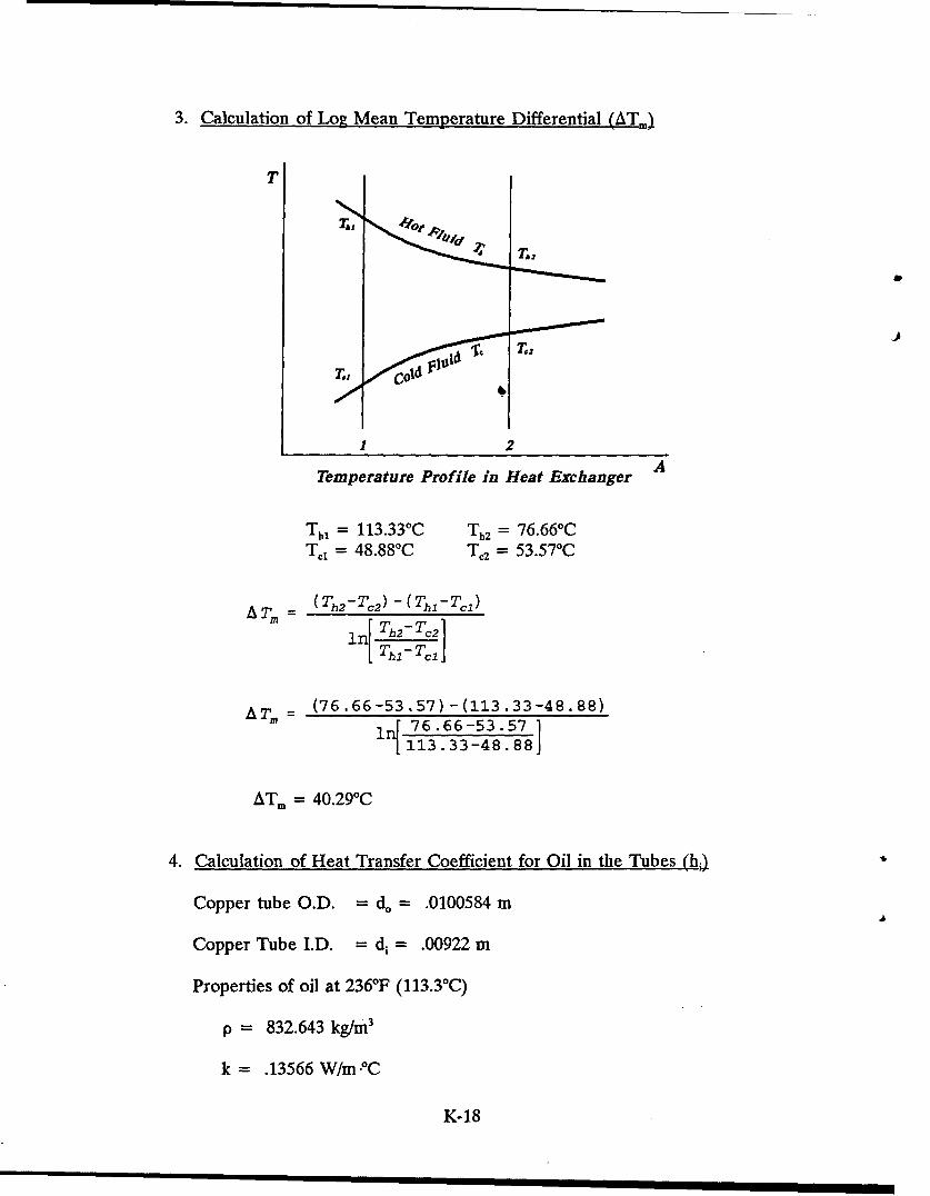
3. Calculation of Log Mean Temperature Differential (ATm)
T
2
Temperature Profile in Heat Exchanger A
Thl = 113.330 C Th2 = 76.660CTa = 48.88'C T,2 = 53.57 0C
ATm = (Th2 -T12 )-(ThI-Tl)
n[ Th2-TC2 1[ 7hAT,= (76.66-53.57)-(113.33-48.88)
1 q 76.66-53.571
113.33-48.88j
ATm = 40.29-C
4. Calculation of Heat Transfer Coefficient for Oil in the Tubes (h.)
Copper tube O.D. = d. = .0100584 m
Copper Tube I.D. = di= .00922 m
Properties of oil at 236°F (113.3°C)
p = 832.643 kg/m3
k = .13566 W/m-PC
K-18
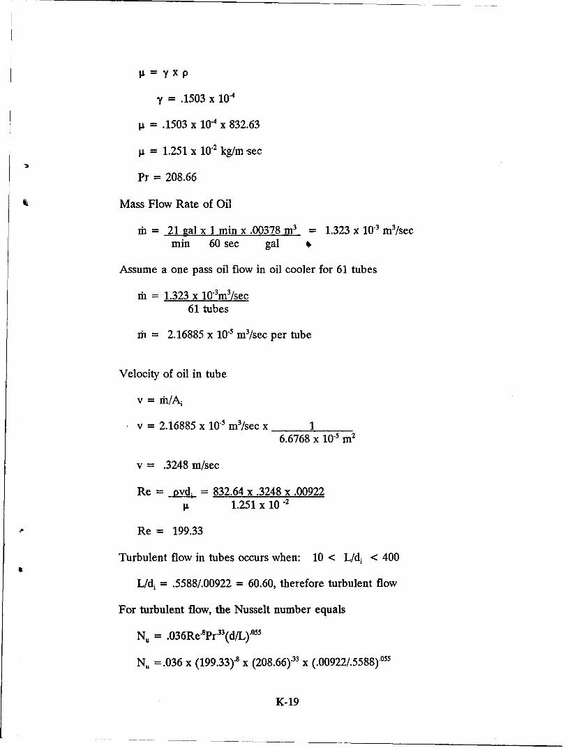
y = .1503 x 10.4
.= .1503 x 10-4 x 832.63
p. = 1.251 x 10.2 kg/m sec
Pr = 208.66
Mass Flow Rate of Oil
ih = 21 gal x 1 min x .00378 m3 = 1.323 x 10⁻³ m3/secmin 60 sec gal
Assume a one pass oil flow in oil cooler for 61 tubes
mh = 1.323 x 10³m3/sec61 tubes
d = 2.16885 x 10s m3/sec per tube
Velocity of oil in tube
v = fr/A-
v = 2.16885 x 10⁻⁵ m3/sec x 16.6768 x 10- m2
v = .3248 m/sec
Re = _ vd.. = 832.64 x .3248 x .009229 1.251 x 10.2
Re = 199.33
Turbulent flow in tubes occurs when: 10 < L/di < 400
L/di = .5588/.00922 = 60.60, therefore turbulent flow
For turbulent flow, the Nusselt number equals
NU = .036Re'8 Pr'3 3(d/L)"0 55
NU =.036 x (199.33).8 x (208.66).33 x (.00922/.5588).055
K-19
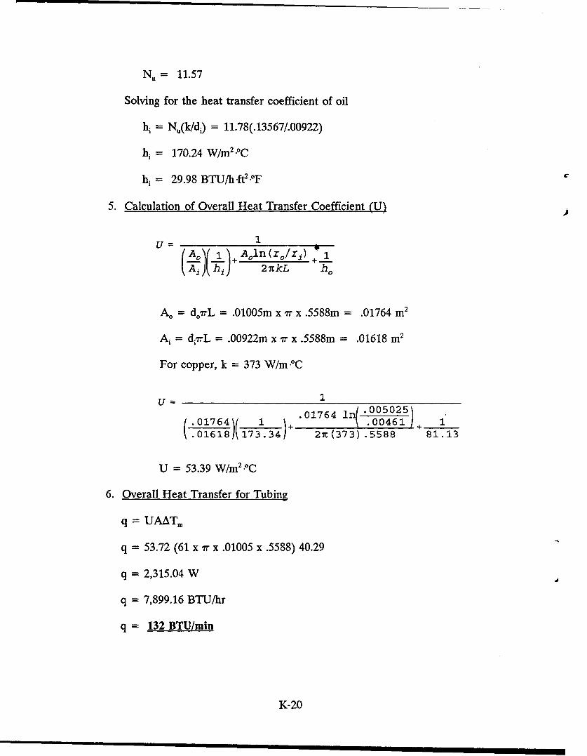
N. = 11.57
Solving for the heat transfer coefficient of oil
hi = N,(k/di) = 11.78(.13567/.00922)
hi = 170.24 W/m2.- C
hi = 29.98 BTU/h'ft2 .OF
5. Calculation of Overall Heat Transfer Coefficient (U) )
1U = 1 )Ao] l_)Aoln(r0 /r1 )+ 1Ai hi 2k ho
A. = d0 rL = .01005m x yr x .5588m = .01764 m2
A= d•-L = .00922m x 7 x .5588m = .01618 m2
For copper, k = 373 W/m .C
U = 1.01764 005025)
(01764)( 1 + '.00461 1.01618 173.34 27t (373) .5588 81.13
U = 53.39 W/m 2.oC
6. Overall Heat Transfer for Tubing
q = UAAT.
q = 53.72 (61 x ir x .01005 x .5588) 40.29
q = 2,315.04 W
q = 7,899.16 BTU/hr
q = 132 BTU/min
K-20
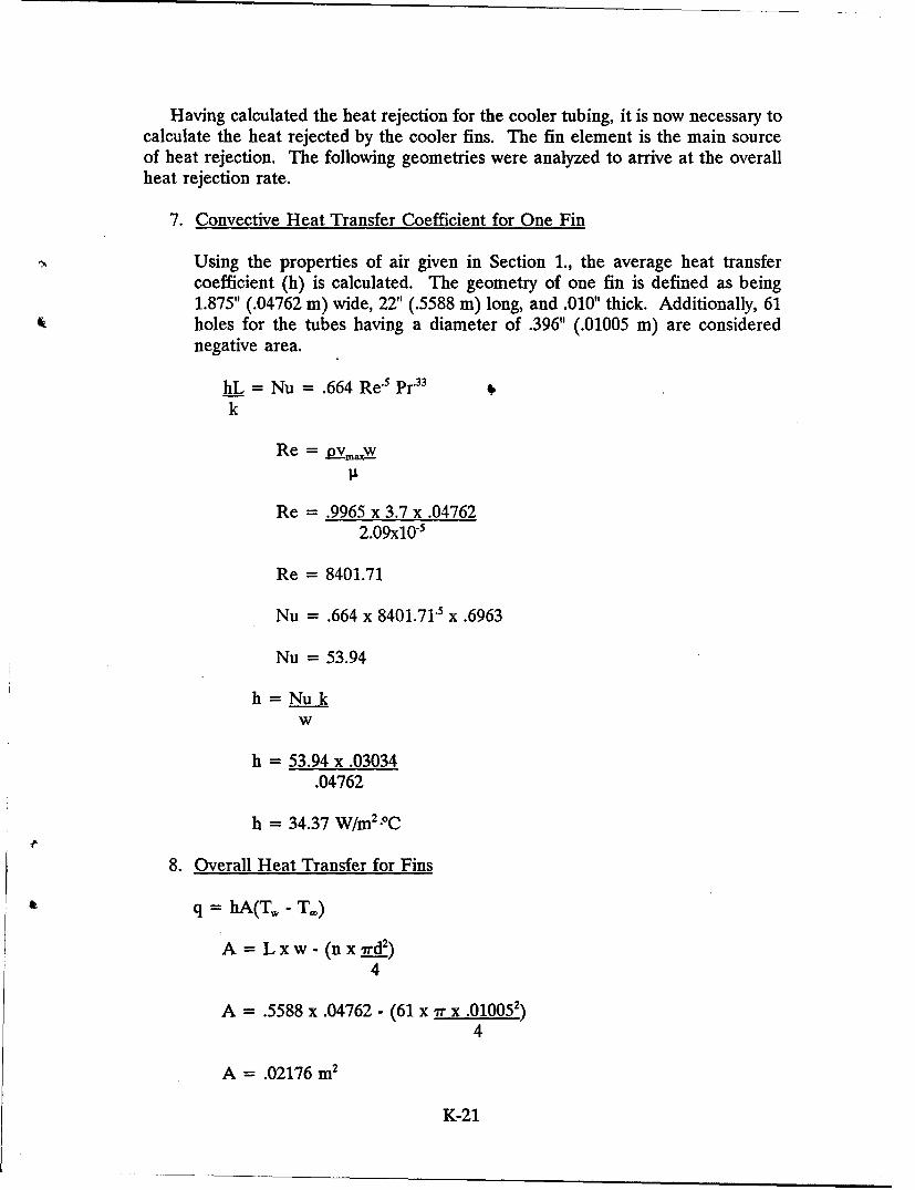
Having calculated the heat rejection for the cooler tubing, it is now necessary tocalculate the heat rejected by the cooler fins. The fin element is the main sourceof heat rejection. The following geometries were analyzed to arrive at the overallheat rejection rate.
7. Convective Heat Transfer Coefficient for One Fin
Using the properties of air given in Section 1., the average heat transfercoefficient (h) is calculated. The geometry of one fin is defined as being1.875" (.04762 m) wide, 22" (.5588 m) long, and .010" thick. Additionally, 61holes for the tubes having a diameter of .396" (.01005 m) are considerednegative area.
hL = Nu = .664 Re-5 Pr"33 6
kRe = pvm.,xW
Re = .9965 x 3.7 x .04762
2.09x10⁻⁵
Re = 8401.71
Nu = .664 x 8401.71.5 x .6963
Nu = 53.94
h=Nukw
h = 53.94 x .03034.04762
h = 34.37 W/m2-oC
8. Overall Heat Transfer for Fins
q =hA(T,- T.)
A = Lxw- (nxrxd2)4
A = .5588 x .04762 - (61 x 7r x .010052)4
A = .02176 m2
K-21
q = 34.37 x .02176 (113.33 - 48.88)
q = 48.21 W
q = 2.742 BTU/min (for one fin)
For all the fins in the cooler multiply by 165
q = 452 BTU/min
9. Total Heat Reduction for the Cooler (tubing and fins)
Tubing = 132 BTU/minFins = 452 BTU/min '
584 BTU/min Total Heat Rejection by the Cooler
Appendix K List of References
BBaumeister, Theodore, and Marks, Lionel S., "Standard Handbook for Mechanical
Engineers," McGraw-Hill Book Co., NY, p. 4-106 (1967)
b Baumeister, Theodore, and Marks, Lionel S., "Standard Handbook for Mechanical
Engineers," McGraw-Hill Book Co., NY, p. 4-106 (1967)
Baumeister, Theodore, and Marks, Lionel S., "Standard Handbook for Mechanical
Engineers," McGraw-Hill Book Co., NY, p. 4-106 (1967)
d Baumeister, Theodore, and Marks, Lionel S., "Standard Handbook for Mechanical
Engineers," McGraw-Hill Book Co., NY, p. 4-106 (1967)
Holman, J.P., "Heat Transfer," McGraw-Hill Book Co., NY, p. 641 (1986)
f Holman, J.P., "Heat Transfer," McGraw-Hill Book Co., NY, p. 300 (1986)
g Holman, J.P., "Heat Transfer," McGraw-Hill Book Co., NY, p. 300 (1986)
K-22
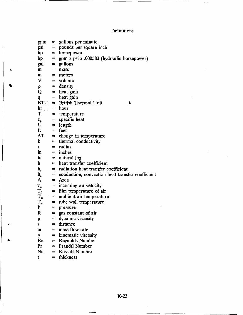
Definitions
gpm = gallons per minutepsi = pounds per square inchhp = horsepowerhp = gpm x psi x .000583 (hydraulic horsepower)gal = gallonsIm = massm = metersV = volumep = densityQ = heat gainq = heat gainBTU = British Thermal Unit 0hr = hourT = temperaturec, = specific heatL = lengthft = feetAT = change in temperaturek = thermal conductivityr = radiusin = inchesIn = natural logh = heat transfer coefficienthr = radiation heat transfer coefficienthc = conduction, convection heat transfer coefficientA = Areav. = incoming air velocityTf = film temperature of airT. = ambient air temperatureTw, = tube wall temperatureP = pressureR = gas constant of airIL = dynamic viscosity
1• s = distance]h = mass flow rateY = kinematic viscosityRe = Reynolds NumberPr = Prandtl NumberNu = Nussult Numbert = thickness
K-23
K'it
K{-24
DISTRIBUTION LIST
Copies
Commander 12Defense Technical Information CenterBldg. 5, Cameron StationATTN: DDACAlexandria, VA 22304-9990
Manager 2Defense Logistics Studies Information ExchangeATIfN: AMXMC-DFort Lee, VA 23801-6044
Commander 2U.S. Army Tank-Automotive CommandATTN: ASQNC-TAC-DIT (Technical Library)Warren, MI 48397-5000
CommanderU.S. Army Tank-Automotive CommandATTN: AMSTA-CF (Dr. Oscar)Warren, MI 48397-5000
CommanderU.S. Army Tank-Automotive CommandATTN: AMSTA-Z (Colonel Boudreau)Warren, MI 48397-5000
Commander 2U.S. Army Tank-Automotive CommandATrN: AMSTA-Z-IRV (MAJ Schumacher)Warren, MI 48397-5000
CommanderU.S. Army Tank-Automotive CommandATTN: AMSTA-ZDS (Mr. Sloss)
$ Warren, MI 48397-5000
DirectorU.S. Army Material Systems Analysis ActivityATTN: AMXSY-MP (Mr. Cohen)Aberdeen Proving Ground, MD 21005-5071
DIST-1


![[ENG] Hacker halted 2012 - Zombie browsers, spiced with rootkit extensions](https://static.fdocuments.us/doc/165x107/55756c09d8b42a2e248b4d6b/eng-hacker-halted-2012-zombie-browsers-spiced-with-rootkit-extensions.jpg)