NNB GENERATION COMPANY LTD COMPANY D - … · 2 STRESS TEST ASSESSMENT PROCESS ... Company Document...
50
NOT PROTECTIVELY MARKED UNCONTROLLED WHEN PRINTED NOT PROTECTIVELY MARKED NNB GENERATION COMPANY LTD COMPANY DOCUMENT UK EPR: RESPONSE TO EU “STRESS TESTS” CHAPTER 0: EXECUTIVE SUMMARY Version 3.0 Date of Issue 16/11/2011 Document No. NNB-OSL-REP-001159 Next Review Date N/A Owner & Approver M Lavelle Author I G Cain Position Safety Case Team Leader © 2011 Published in the United Kingdom by NNB Generation Company Limited (NNB GenCo), 90 Whitfield Street - London, W1T 4EZ. All rights reserved. No part of this publication may be reproduced or transmitted in any form or by any means, including photocopying and recording, without the written permission of the copyright holder NNB GenCo, application for which should be addressed to the publisher. Such written permission must also be obtained before any part of this publication is stored in a retrieval system of any nature. Requests for copies of this document should be referred to Head of Management Arrangements, NNB Generation Company Limited (NNB GenCo), 90 Whitfield Street - London, W1T 4EZ. The electronic copy is the current issue and printing renders this document uncontrolled. Controlled copy-holders will continue to receive updates as usual.
Transcript of NNB GENERATION COMPANY LTD COMPANY D - … · 2 STRESS TEST ASSESSMENT PROCESS ... Company Document...

NOT PROTECTIVELY MARKED
UNCONTROLLED WHEN PRINTED NOT PROTECTIVELY MARKED
NNB GENERATION COMPANY LTD
COMPANY DOCUMENT
UK EPR: RESPONSE TO EU “STRESS TESTS”
CHAPTER 0: EXECUTIVE SUMMARY
Version 3.0
Date of Issue 16/11/2011
Document No. NNB-OSL-REP-001159
Next Review Date N/A
Owner & Approver M Lavelle
Author I G Cain
Position Safety Case Team Leader
© 2011 Published in the United Kingdom by NNB Generation Company Limited (NNB GenCo), 90 Whitfield Street - London, W1T 4EZ. All rights reserved. No part of this publication may be reproduced or transmitted in any form or by any means, including photocopying and recording, without the written permission of the copyright holder NNB GenCo, application for which should be addressed to the publisher. Such written permission must also be obtained before any part of this publication is stored in a retrieval system of any nature. Requests for copies of this document should be referred to Head of Management Arrangements, NNB Generation Company Limited (NNB GenCo), 90 Whitfield Street - London, W1T 4EZ. The electronic copy is the current issue and printing renders this document uncontrolled. Controlled copy-holders will continue to receive updates as usual.

NNB GenCo – Company Document NNB-OSL-REP-001159 UK EPR: RESPONSE TO EU “STRESS TESTS” - CHAPTER 0: EXECUTIVE SUMMARY Version 3.0
NOT PROTECTIVELY MARKED
UNCONTROLLED WHEN PRINTED
NOT PROTECTIVELY MARKED Template No. NNB-OSL-TEM-000002 Page 2 of 50 Template Version: 4.0
APPROVAL SIGN-OFF:
DOCUMENT CONTROL
Version Purpose Amendment By Date
1.0 First issue IGC 27.10.2011
2.0 Second issue
Consistency of wording with response to ONR Chief inspector’s report.
IGC 01.11.2011
3.0 Third issue Incorporation of NSC recommended amendments. For issue
IGC 16.11.2011
NNB GenCo – Company Document NNB-OSL-REP-001159 UK EPR: RESPONSE TO EU “STRESS TESTS” - CHAPTER 0: EXECUTIVE SUMMARY Version 3.0
NOT PROTECTIVELY MARKED
UNCONTROLLED WHEN PRINTED
NOT PROTECTIVELY MARKED Template No. NNB-OSL-TEM-000002 Page 3 of 50 Template Version: 4.0
TABLE OF CONTENTS
1 INTRODUCTION .....................................................................................................4
1.1 Purpose............................................................................................................................... 4
1.2 Scope .................................................................................................................................. 5
1.3 Status of the Stress Tests Report..................................................................................... 5
1.4 References and Definitions............................................................................................... 6
2 STRESS TEST ASSESSMENT PROCESS ............................................................8
2.1 Definition............................................................................................................................. 8
2.2 Scope .................................................................................................................................. 9
3 THE UK EPR .........................................................................................................10
3.1 Generic Design Features................................................................................................. 10
3.2 Site Specific Features (Hinkley Point C) ........................................................................ 11
4 STRESS TEST ASSESSMENT.............................................................................13
4.1 Initiating Event (Hazard) Assessment ............................................................................ 13
4.2 Loss of Safety Function Assessment ............................................................................ 25
4.3 Severe Accident Assessment ......................................................................................... 38
5 FURTHER ASSESSMENTS of the UK EPR DESIGN..........................................43
5.1 Technical Reviews ........................................................................................................... 43
5.2 NNB Response to the Weightman Report into the Fukushima Event......................... 44
5.3 Generic Design Assessment Issue ................................................................................ 44
6 ACTION PLAN ......................................................................................................45
6.1 Quality Assurance Arrangements .................................................................................. 45
6.2 Summary of Identified Areas for Consideration............................................................ 45
6.3 Resilience Assessment ................................................................................................... 46
6.4 Follow on Work ................................................................................................................ 47
7 CONCLUSIONS ....................................................................................................48
TABLES
FIGURES

NNB GenCo – Company Document NNB-OSL-REP-001159 UK EPR: RESPONSE TO EU “STRESS TESTS” - CHAPTER 0: EXECUTIVE SUMMARY Version 3.0
NOT PROTECTIVELY MARKED
UNCONTROLLED WHEN PRINTED
NOT PROTECTIVELY MARKED Template No. NNB-OSL-TEM-000002 Page 4 of 50 Template Version: 4.0
1 INTRODUCTION
1.1 Purpose
1.1.1 Following consideration of the accident which occurred at the Fukushima Daiichi nuclear power plant in Japan on March 11th 2011, the European Council of March 24th and 25th declared that “the safety of all EU plants should be reviewed, on the basis of a comprehensive and transparent risk assessment (“stress tests”); the European Nuclear Safety Regulatory Group (ENSREG) and the commission are invited to develop as soon as possible the scope and modalities of these tests in a coordinated framework in the light of the lessons learned from the accident in Japan and with the full involvement of the Member States, making full use of available expertise (notably from the Western European Nuclear Regulators Association); the assessments will be conducted by independent national authorities and through peer review; their outcome and any necessary subsequent measures that will be taken should be shared with the Commission and within the ENSREG and should be made public; the European Council will assess initial findings by the end of 2011, on the basis of a report from the Commission".
1.1.2 The purpose of the stress tests is to confirm the ongoing safety of nuclear power plants operated in the EU and also to identify further improvements in line with the fundamental principle of the continuous improvement of nuclear safety.
1.1.3 This report provides the summary of the prospective Licensee’s response (NNB GenCo) for the stress tests applied to the proposed European Pressurised Water Reactor design intended for use in the UK (UK EPR). The full response to the ENSREG specification is provided in Chapters 1 to 6 of the report. The specification produced by ENSREG stated that only existing plants or plants under construction were required to subject their plant to the stress tests and as such the UK EPR falls outside of this requirement since it is still at the pre-construction phase. However, NNB GenCo as a prospective Licensee has taken the decision to subject the UK EPR to the stress tests at this early stage of design to ensure that any appropriate lessons learnt from the Fukushima event are incorporated in to the final design. This summary and the associated chapters 1 to 6 are intended for submission to the Office for Nuclear Regulation (ONR).
1.1.4 In addition, this report pulls together the findings from other assessments made of the UK EPR design in light of the events at Fukushima, notably those produced by NNB GenCo in response to the ONR Chief Inspector’s report and those produced by the Requesting Parties as part of the Generic Design Assessment (GDA) process.
NNB GenCo – Company Document NNB-OSL-REP-001159 UK EPR: RESPONSE TO EU “STRESS TESTS” - CHAPTER 0: EXECUTIVE SUMMARY Version 3.0
NOT PROTECTIVELY MARKED
UNCONTROLLED WHEN PRINTED
NOT PROTECTIVELY MARKED Template No. NNB-OSL-TEM-000002 Page 5 of 50 Template Version: 4.0
1.1.5 Finally, the report identifies the measures which are to be subject to further consideration for incorporation into the UK EPR design and prospective Licensee emergency arrangements. Where these occur in the report these are highlighted in bold italicised text.
1.2 .Scope
1.2.1 The “stress tests” have been applied to the UK EPR design generically and specifically to the twin unit installation proposed for the Hinkley Point C site. Consideration will be given to other future proposed EPR sites in the UK, most notably the Sizewell C site. However, due to the reduced level of development at this stage an in depth assessment to the level achievable at Hinkley Point C is not possible. Notwithstanding this any relevant outcomes from the “stress tests” will be incorporated into the Sizewell C design.
1.2.2 Whilst the European Commission called for comprehensive tests that embrace both natural and manmade hazards, risks due to security threats are not part of the mandate of ENSREG and the prevention and response to incidents due to malevolent or terrorist acts (including aircraft crashes) are considered elsewhere.
1.3 Status of the Stress Tests Report
1.3.1 The assessment of the UK EPR design against the ENSREG-specified stress tests is regarded by NNB GenCo as a regulator requested safety review as a result of the events which occurred at the Fukushima Daiichi plant in March 2011. This review is carried out with the aim of providing the Architect Engineer and the prospective Licensee with the opportunity to:
confirm that the design basis of the plant to extreme events is sound,
identify the margin between the design basis and any potential cliff edge effects (a cliff edge effect is characterised by the fact that after a certain level, an increase of the hazard magnitude leads to a pronounced, disproportionate increase in the consequences),
identify potential areas for consideration as changes to the design and/or organisational arrangements.
1.3.2 As such the stress tests report is not considered to constitute a formal part of the safety case for the proposed Hinkley Point C power station, or for that matter any future EPR built in the UK. The formal specification of the UK EPR design will be made in the system design manuals (SDM) and the safety case in the various safety reports (i.e. PCSR, PCmSR, POSR and SSR). At the time of writing the GDA has been completed to step 4 (thorough and detailed examination of the evidence, on a sampling basis, given by the safety analysis) and the schedule of all of the issues still to be addressed before GDA can be considered complete, together with the requesting parties’ resolution plans have now been published. In parallel with this NNB GenCo is producing the site-specific Pre-Construction Safety Report (PCSR) for Hinkley Point C which is based heavily on the GDA PCSR but with site specific

NNB GenCo – Company Document NNB-OSL-REP-001159 UK EPR: RESPONSE TO EU “STRESS TESTS” - CHAPTER 0: EXECUTIVE SUMMARY Version 3.0
NOT PROTECTIVELY MARKED
UNCONTROLLED WHEN PRINTED
NOT PROTECTIVELY MARKED Template No. NNB-OSL-TEM-000002 Page 6 of 50 Template Version: 4.0
features taken in to account i.e. site characterisations for hazards and site specific ultimate heat sink design. The various safety case reports will be subject to formal Independent Peer Review (IPR) as part of the safety case development process. In addition, the technical reviews (see section 5.1) carried out by personnel within NNB GenCo and assisted by the Architect Engineer represent a very effective independent line of peer review of the assessments presented as part of the stress tests. Finally, this summary document has been subject to review by the Director of the NNB GenCo Safety Directorate, which is independent of the Design Authority which has been responsible for the production of the stress tests report. It is for these reasons that formal IPR is not considered necessary or appropriate for the stress tests report.
1.3.3 The major information source for the stress tests report has been the equivalent report produced by EDF SA for the Flamanville 3 (FA3) Nuclear Power Plant. This approach has been adopted due to its role in being the basis for the design of the UK EPR submitted for the GDA process. The plant at FA3 is under construction and hence at a more advanced stage than Hinkley Point C. This provides useful feedback in support of the design for Hinkley Point C since it is at an early enough stage to enable it to incorporate design changes and site specific adaptations. The FA3 report has been supplemented with information provided from within EDF Energy for licensee specific organisational arrangements. Information regarding generic plant features has been obtained from the GDA PCSR, whereas site-specific information for the proposed Hinkley Point C site has been extracted from the Hinkley Point C PCSR, the second version of which is currently in production.
1.4 References and Definitions
Ref Title Location Document No.
1 ENSREG EU “Stress tests” specifications
2 GDA PCSR
3 HPC PCSR (PCSR1)
Term / Abbreviation Definition
AE Architect Engineer
ALARP As Low as Reasonably Practicable
ASN Autorité de sûreté nucléaire (French nuclear regulatory authority)
CCWS Component Cooling Water System
CHRS Containment Heat Removal System
CVCS Chemical & Volume Control System
DBE Design Basis Earthquake
DIN Division Ingénierie Nucléaire (Nuclear Engineering Division of EDF SA)
EDG Emergency Diesel Generator

NNB GenCo – Company Document NNB-OSL-REP-001159 UK EPR: RESPONSE TO EU “STRESS TESTS” - CHAPTER 0: EXECUTIVE SUMMARY Version 3.0
NOT PROTECTIVELY MARKED
UNCONTROLLED WHEN PRINTED
NOT PROTECTIVELY MARKED Template No. NNB-OSL-TEM-000002 Page 7 of 50 Template Version: 4.0
Term / Abbreviation Definition
EFWS Emergency Feed Water System
ENSREG European Nuclear Safety Regulatory Group
EPR European Pressurised Water Reactor
ESWS Essential Service Water System
FA3 Flamanville 3
FPCS Fuel Pool Cooling System
GDA Generic Design Assessment
HPC Hinkley Point C
HVAC Heating, Ventilation and Air Conditioning
IPR Independent Peer Review
IRWST In Reactor Water Storage Tank
ISFS Interim Spent Fuel Store
JAC Fire Fighting Water Supply System
LHSI Low Head Safety Injection
LOCA Loss of Coolant Accident
LOOP Loss of Off-site Power
NPP Nuclear Power Plant
ONR Office for Nuclear Regulation
OPEX Operating Experience
PCSR Pre-Construction Safety Report
PCmSR Pre-Commissioning Safety Report
POSR Pre-Operation Safety Report
RBWMS Reactor Boron and Water Make-up System
RCP Reactor Coolant Pump
RCS Reactor Coolant System
RHRS Residual Heat Removal System
SCWS Safety Chilled Water System
SDM System Design Manual
SQEP Suitably Qualified and Experienced Personnel
SSR Site Safety Report
SSSS Standstill Seal System
Stress test A targeted reassessment of the safety margins of nuclear power plants in light of the events which occurred at Fukushima: extreme natural events challenging the plant safety functions and leading to a severe accident
UDG Ultimate Diesel Generator (sometimes called station blackout (SBO) diesel generator)
WENRA Western European Nuclear Regulators Association

NNB GenCo – Company Document NNB-OSL-REP-001159 UK EPR: RESPONSE TO EU “STRESS TESTS” - CHAPTER 0: EXECUTIVE SUMMARY Version 3.0
NOT PROTECTIVELY MARKED
UNCONTROLLED WHEN PRINTED
NOT PROTECTIVELY MARKED Template No. NNB-OSL-TEM-000002 Page 8 of 50 Template Version: 4.0
2 STRESS TEST ASSESSMENT PROCESS
2.1 Definition
2.1.1 The term “stress test” is defined in reference 1 as a targeted reassessment of the safety margins of nuclear power plants in light of the events which occurred at Fukushima: extreme natural events challenging the plant safety functions and leading to a severe accident. This reassessment will consist of:
An evaluation of the response of the nuclear power plant when facing a set of extreme situations. These extreme situations are summarised in section 4 below,
A verification of the preventative and mitigative measures chosen following a defence-in-depth logic; initiating events, consequential loss of safety functions, severe accident management.
2.1.2 In the extreme situations to be considered sequential loss of the lines of defence is assumed in a deterministic approach irrespective of the probability of the loss and whether failure is within or beyond the design basis. In particular it is kept in mind that loss of safety functions and severe accident situations can only occur when a number of design provisions have failed. In addition, measures to manage these situations will be assumed to be progressively defeated.
2.1.3 For the plant under consideration the reassessment will report on the predicted response of the plant and the effectiveness of the preventative measures employed, noting any potential weak points and/or cliff-edge effects (i.e. situations in which a small increase in a particular aspect of an event results in a disproportionate increase in its severity), for each of the extreme situations considered. This is to evaluate the robustness of the defence-in-depth approach, the adequacy of existing accident management measures and to identify the potential for improvements, both technical and organisational (such as procedures, human resources, emergency response organisation and use of use of external resources).
2.1.4 By their nature the stress tests will focus on measures that could be taken following the loss of the safety systems that are installed to provide protection from accidents considered in the plant design. Whilst the assessment of the adequate performance of these systems will form an integral part of the licensing of the plant, assumptions concerning their performance are to be re-examined in the stress tests and they should be shown as provisions in place. It is recognised that all measures taken to protect fuel integrity (whether in the core or the spent fuel pools) or to protect the reactor containment integrity constitute an essential part of the defence-in-depth, as it is always better to prevent the occurrence of accidents than to deal with the consequences.

NNB GenCo – Company Document NNB-OSL-REP-001159 UK EPR: RESPONSE TO EU “STRESS TESTS” - CHAPTER 0: EXECUTIVE SUMMARY Version 3.0
NOT PROTECTIVELY MARKED
UNCONTROLLED WHEN PRINTED
NOT PROTECTIVELY MARKED Template No. NNB-OSL-TEM-000002 Page 9 of 50 Template Version: 4.0
2.2 Scope
2.2.1 The scope of the stress tests is focussed on the events that occurred at Fukushima Daiichi, including combination of initiating events and failures. Specifically the focus is on the following issues:
1) the initiating events of earthquake and flooding, with consideration given to extreme weather,
2) the consequences of loss of safety function from any initiating event conceivable at the site including loss of electrical power (including station black out), loss of ultimate heat sink and/or a combination of both,
3) severe accident management issues including means to protect and manage loss of core cooling and fuel storage pool cooling and loss of containment integrity.
2.2.2 It should be noted that 2) and 3) above are not limited to earthquake and tsunami; flooding will be included regardless of its source. Extreme weather conditions will also be included. It should be noted that the full range of hazards (external and internal) identified for the sites designated for the UK EPR will be considered as part of the formal safety case.
2.2.3 The assessment of the consequences of loss of safety functions is relevant if the situation is provoked by indirect initiating events, for instance large disturbance of the electrical power distribution grid impacting on-site AC power distribution systems. The stress tests specification assumes that the site is isolated from delivery of heavy material for 72 hours by road, rail or waterways. Portable light equipment can arrive to the site from other locations after the first 24 hours.
2.2.4 Whilst the review of the severe accident management issues primarily focuses on the licensee’s provisions it does also include relevant off-site support for maintaining the safety functions of the plant. However, the emergency preparedness measures of the emergency services and other public protection agencies are outside of the scope of the stress tests.

NNB GenCo – Company Document NNB-OSL-REP-001159 UK EPR: RESPONSE TO EU “STRESS TESTS” - CHAPTER 0: EXECUTIVE SUMMARY Version 3.0
NOT PROTECTIVELY MARKED
UNCONTROLLED WHEN PRINTED
NOT PROTECTIVELY MARKED Template No. NNB-OSL-TEM-000002 Page 10 of 50 Template Version: 4.0
3 THE UK EPR
3.1 Generic Design Features
3.1.1 The EPR is a pressurised water reactor whose design combines familiar and proven technology based on the most recent French N4 and German KONVOI pressurised water reactors. The design of the reactor unit represents an evolution in PWR technology and introduces some new features including improved protection against and mitigation for core meltdown, increased robustness against external hazards, in particular aircraft crashes and earthquakes and a set of safeguard systems ensuring a quadruple redundancy. The functioning of the nuclear production unit is based on a primary system, a secondary system and an ultimate cooling system.
3.1.2 The primary system is a closed water-filled pressurised system installed in a leak tight steel and concrete enclosure, the reactor building. It comprises a reactor, namely a steel vessel containing the nuclear fuel (reactor core) and four cooling loops, each containing a reactor coolant pump and a steam generator. The reactor is a light water moderated and cooled design utilising low-enriched uranium fuel clad in a zirconium alloy. The reactor has a rated thermal power of 4,500 MW. The heat produced by the nuclear reaction inside the reactor vessel is extracted by the pressurised water which circulates in the primary system. The heated water then passes through the steam generators. Here the heat is transferred to the water of the secondary system which flows between the steam generator tubes.
3.1.3 The secondary system is a closed system which is independent of the primary system. It supplies steam to the turbine generator set located in the turbine hall. Water in this system evaporates in the steam generators heated by the primary system. The steam drives a turbine coupled to the generator which produces electrical energy. After leaving the turbine, the steam is cooled and returned to its liquid state in the condenser and then returned to the steam generator.
3.1.4 The ultimate cooling system is independent of the primary and secondary systems. It cools the condenser by circulating river or sea water. This system can be either open or closed depending on the production unit's construction. An open system refers to circulating water which is directly drawn from and discharged into the sea or a river.
3.1.5 Storage of spent fuel is facilitated by the presence of a cooling pool situated in a dedicated fuel building which forms an integral structure with the reactor building.
3.1.6 The UK EPR has been designed to meet safety objectives for 3rd generation reactors which include reduced core melt frequency, enhanced protection against external and internal hazards, and significant reduction in the radiological risk to the public if a core melt was to occur. The reduced risk of

NNB GenCo – Company Document NNB-OSL-REP-001159 UK EPR: RESPONSE TO EU “STRESS TESTS” - CHAPTER 0: EXECUTIVE SUMMARY Version 3.0
NOT PROTECTIVELY MARKED
UNCONTROLLED WHEN PRINTED
NOT PROTECTIVELY MARKED Template No. NNB-OSL-TEM-000002 Page 11 of 50 Template Version: 4.0
a severe accident (core melt accident) is achieved by the implementation of quadruple redundancy in main safety systems such as the Emergency Feedwater and Safety Injection Systems, and provision of diversified back-up systems which can be used in case of common cause failure of redundant safety trains. Severe accident scenarios have been taken into account at the design stage, the design objective being that only very limited off-site countermeasures would be needed in a core melt accident (no need for emergency evacuation beyond the immediate vicinity of the plant; no permanent relocation or long-term restrictions on the consumption of foodstuffs).
3.2 Site Specific Features (Hinkley Point C)
3.2.1 The site at Hinkley Point is located in the South West Region of England on the Somerset coast, 10 km to the south west of Highbridge and 13 km to the north west of Bridgwater. It is located within the District of West Somerset, and is within close proximity (approximately 3 km) to West Somerset’s boundary with Sedgemoor District. The site is bounded by the Severn Estuary to the north, the Quantock Hills to the south and west and the Polden Hills to the east. The River Parrett lies to the east. The surrounding land is predominantly agricultural and is sparsely populated. The village of Stolford is to the east of the nominated site, the villages of Stockland Bristol, Otterhampton and Coultings to the south-east and the villages of Stogursey, Burton, Shurton and Knighton to the south-west.
3.2.2 The proposed Hinkley Point C power station will be the third power station to be located on the site. The site currently has two first generation UK gas-cooled magnox reactors (Hinkley Point A) which are shutdown, defuelled and in the process of being decommissioned. The site is also home to the twin advanced gas-cooled reactors of Hinkley Point B, which is fully operational. The proposed two UK EPR units of Hinkley Point C will be located to the west of the ‘A’ and ‘B’ stations being adjacent to the ‘A’ station (see figure 1).
3.2.3 The ultimate cooling system (heat sink) for the proposed Hinkley Point C power station will be an ‘open circuit’ system drawing water from the Bristol Channel through two offshore intake tunnels and discharging through a common discharge tunnel. At the onshore end of each intake tunnel the water feeds into an open forebay. The intake water is filtered as it is drawn from each forebay into an adjacent pumping station which supplies the cooling water for a single unit. Once the cooling water for each unit has served its heat removal function it is piped to a discharge pond (one per unit). Each discharge pond is internally sub-divided for the non-safety and safety systems. A diversification system provides an alternative means of supplying the heat sink safety systems with water drawn from the main basin of the discharge pond in the event of loss of the normal heat sink.

NNB GenCo – Company Document NNB-OSL-REP-001159 UK EPR: RESPONSE TO EU “STRESS TESTS” - CHAPTER 0: EXECUTIVE SUMMARY Version 3.0
NOT PROTECTIVELY MARKED
UNCONTROLLED WHEN PRINTED
NOT PROTECTIVELY MARKED Template No. NNB-OSL-TEM-000002 Page 12 of 50 Template Version: 4.0
3.2.4 In addition to the standard EPR design, the proposed Hinkley Point C power station includes the provision of an Interim Spent Fuel Storage (ISFS) facility. This is provided to allow for the on-site storage of long-cooled fuel removed from the spent fuel pools. Whilst the spent fuel pools provide storage capacity for approximately 10 years the ISFS will have the necessary storage capacity to cover the full 60 year operational lifetime of the plant. The design of the ISFS is conceptual at this stage, but the safety case development and design processes will take into account the lessons arising from the earthquake and subsequent tsunami which seriously affected the Fukushima Daiichi nuclear plant in March 2011.
Figure 1: Proposed Site Plot Plan for Hinkley Point C

NNB GenCo – Company Document NNB-OSL-REP-001159 UK EPR: RESPONSE TO EU “STRESS TESTS” - CHAPTER 0: EXECUTIVE SUMMARY Version 3.0
NOT PROTECTIVELY MARKED
UNCONTROLLED WHEN PRINTED
NOT PROTECTIVELY MARKED Template No. NNB-OSL-TEM-000002 Page 13 of 50 Template Version: 4.0
4 STRESS TEST ASSESSMENT
The information contained herein represents NNB GenCo’s current position with respect to the design and safety case for the UK EPR proposed to be built at Hinkley Point C (HPC). However, since the design of the plant has yet to be finalised it is possible that some detailed aspects of the design and/or safety case could change during the course of the plant design and safety case development processes. Nevertheless, it is considered that the assessments provided against the ENSREG stress tests specification are appropriate to the plant design in its current state.
4.1 Initiating Event (Hazard) Assessment
4.1.1 Earthquake
4.1.1.1 Consideration of Design Basis
The identified hazard arising from an earthquake is direct or indirect damage to equipment needed to bring the plant to, and maintain it in, a safe shutdown state. Direct damage is that sustained to systems, structures and components that play a direct role in ensuring nuclear safety which renders them ineffective. Indirect damage is associated with the failure of adjacent equipment or consequential internal hazards resulting from the earthquake (e.g. explosion, fire). Following an earthquake, the objective of the protection is to ensure that the safety functions needed to return and maintain the plant in a safe shutdown state are not unacceptably affected. As such structures, systems and components must be designed so that they are able to fulfil their functions, maintain their integrity or remain stable under the conditions caused by the postulated seismic movements.
Seismological conditions in the Hinkley Point area have been studied in detail on numerous occasions. The Seismic Hazards Working Party (SHWP) produced two reports specific to the Hinkley Point site in 1987 and 1991. In 2009, AMEC-Geomatrix performed a probabilistic study in order to take into account some advances that have occurred since the production of the SHWP reports, such as an updated catalogue of earthquakes and new and more robust ground motion prediction models. The output from this work is to obtain the 10,000 year return time uniform hazard spectrum (essentially a relationship between the assumed acceleration as a function of frequency).
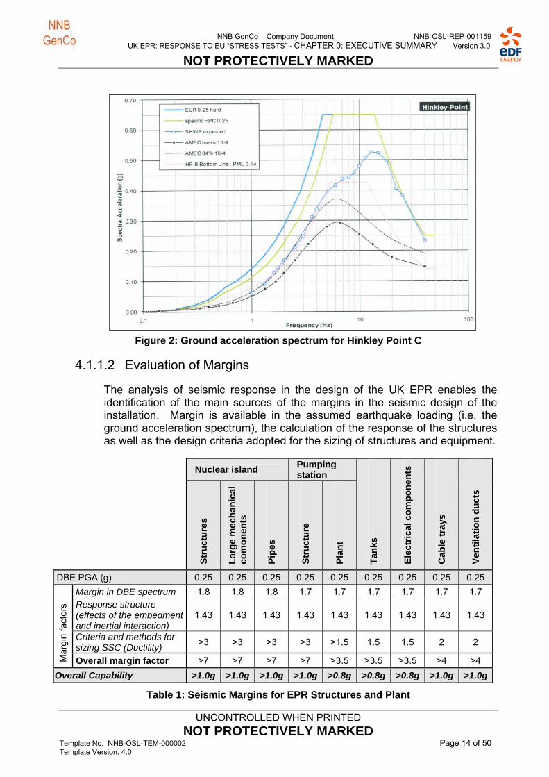
The approach taken to the assessment of earthquakes is to select a suitable design ground acceleration spectrum and to use this in combination with six different ground conditions for the analysis of the seismic response of each building of the nuclear island. These analyses provide the in-structure spectra for the design and/or qualification of the safety related structures, systems and components. For the UK EPR the peak horizontal design acceleration is taken as 0.25 g, whereas the equivalent value (at an 84% confidence level) obtained for the HPC site is 0.19 g. Detailed comparison between the adopted design spectrum and the uniform hazard spectrum obtained for the HPC site show that the former is comfortably bounding at all frequencies (see following figure 2).
NNB GenCo – Company Document NNB-OSL-REP-001159 UK EPR: RESPONSE TO EU “STRESS TESTS” - CHAPTER 0: EXECUTIVE SUMMARY Version 3.0
NOT PROTECTIVELY MARKED
UNCONTROLLED WHEN PRINTED
NOT PROTECTIVELY MARKED Template No. NNB-OSL-TEM-000002 Page 14 of 50 Template Version: 4.0
Figure 2: Ground acceleration spectrum for Hinkley Point C
4.1.1.2 Evaluation of Margins
The analysis of seismic response in the design of the UK EPR enables the identification of the main sources of the margins in the seismic design of the installation. Margin is available in the assumed earthquake loading (i.e. the ground acceleration spectrum), the calculation of the response of the structures as well as the design criteria adopted for the sizing of structures and equipment.
Nuclear island Pumping station
Str
uct
ure
s
Lar
ge
mec
han
ical
co
mo
nen
ts
Pip
es
Str
uct
ure
Pla
nt
Tan
ks
Ele
ctri
cal c
om
po
nen
ts
Cab
le t
rays
Ven
tila
tio
n d
uct
s
DBE PGA (g) 0.25 0.25 0.25 0.25 0.25 0.25 0.25 0.25 0.25
Margin in DBE spectrum 1.8 1.8 1.8 1.7 1.7 1.7 1.7 1.7 1.7 Response structure (effects of the embedment and inertial interaction)
1.43 1.43 1.43 1.43 1.43 1.43 1.43 1.43 1.43
Criteria and methods for sizing SSC (Ductility)
>3 >3 >3 >3 >1.5 1.5 1.5 2 2
Mar
gin
fact
ors
Overall margin factor >7 >7 >7 >7 >3.5 >3.5 >3.5 >4 >4
Overall Capability >1.0g >1.0g >1.0g >1.0g >0.8g >0.8g >0.8g >1.0g >1.0g
Table 1: Seismic Margins for EPR Structures and Plant

NNB GenCo – Company Document NNB-OSL-REP-001159 UK EPR: RESPONSE TO EU “STRESS TESTS” - CHAPTER 0: EXECUTIVE SUMMARY Version 3.0
NOT PROTECTIVELY MARKED
UNCONTROLLED WHEN PRINTED
NOT PROTECTIVELY MARKED Template No. NNB-OSL-TEM-000002 Page 15 of 50 Template Version: 4.0
The margin factor in the Design Basis Earthquake (DBE) spectrum is a reflection of the ‘headroom’ available between the ground acceleration of the design spectrum and that of the local site spectrum (“AMEC 84% 10-4”) over the frequency range 1 to 10 Hz, as shown in figure 2 above.
In the absence of a Hinkley Point site-specific value the quoted factor of 1.43 for the response of structures is taken from the equivalent FA3 assessment. The exact value of the factor is dependent on the prevailing ground conditions of the site. However, even if the factor was only worth half of that quoted above, substantial margins to the DBE would remain. It should be noted that the design basis seismic assessment considers a range of possible soil and rock types.
The criteria and methods of sizing tend to represent the largest source of margin and is a reflection of the inherent conservatism associated with nuclear design practices. This is also supported by the results from experiments and model tests and inspection evidence of equipment following seismic events.
In table 1 above the overall margin factor is the combination of the three margin factors described above. Whereas the overall seismic capability is the design basis peak ground acceleration (0.25 g) multiplied by the structure response and sizing criteria and methods margin factors. The results from table 1 indicate that the seismic capability of the structure and equipment whose failure would lead to the inability of plant to execute its safety function requirements are greater than 0.8g, with that of the Nuclear Island greater than 1.0g. This level significantly exceeds the 1 in 10,000 year return frequency DBE.
It is concluded that the design basis for the proposed twin UK EPR power station at Hinkley Point C to seismic events is confirmed to be appropriate in light of the events of Fukushima.
4.1.1.3 Identification of Cliff Edge Effects
A cliff edge effect is characterised by the fact that after a certain level, a small increase in hazard magnitude results in a disproportionate increase in its severity. The seismic assessments completed for the GDA show that the piping systems are very robust. Whilst lower margins exist for electrical equipment these are still considered to be robust. As such any cliff edge effect is likely to appear only for very high levels of earthquake, well in excess of any which is predicted for the UK.
For the UK EPR the cliff edge is likely to have no effect on equipment and buildings necessary to provide protection against the earthquake, even at levels well above the design i.e. no cliff edge effect is apparent up to ground accelerations of 0.9g. According to a Tokyo Electric Power Company report the maximum recorded peak ground acceleration at the Fukushima Daiichi plant was equivalent to 0.561g at Unit 2.
4.1.1.4 Measures to be considered to Improve Robustness of the Plant
Considering the moderate levels of seismic activity associated with the proposed UK EPR sites and the existence of the large safety margins identified

NNB GenCo – Company Document NNB-OSL-REP-001159 UK EPR: RESPONSE TO EU “STRESS TESTS” - CHAPTER 0: EXECUTIVE SUMMARY Version 3.0
NOT PROTECTIVELY MARKED
UNCONTROLLED WHEN PRINTED
NOT PROTECTIVELY MARKED Template No. NNB-OSL-TEM-000002 Page 16 of 50 Template Version: 4.0
above, no requirement is identified to enhance the seismic design of the UK EPR to avoid ‘cliff-edge effects’.
However, the identification of the use of the raw water storage system to provide the ultimate water supply in the event of a severe accident (see 4.2) requires the seismic qualification of the piping, valves and pumps to ensure water distribution for these needs.
4.1.2 Flooding
4.1.2.1 Consideration of Design Basis
Flooding hazards can arise from a wide variety of sources. These are broadly divided into two main areas; those arising from extreme sea conditions and those arising from other sources (i.e. river flooding, rainfall, flooding from artificial sources). Both are discussed in the following section;
Flooding from extreme sea conditions
There are two kind of extreme sea conditions for the flooding from the sea:
Extreme seawater level (without waves),
Extreme seawater levels (including waves).
The relevant extreme seawater level must be chosen for each fault scenario dependent on the expected fault conditions and fault location. For each scenario the 10,000 year return time period condition must be established, including an assessment of the reasonably foreseeable climate change conditions over a 100 year period.
The T1,000 and T10,000 extreme sea levels have been combined with an increase in sea level due to climate change of 0.9 m in 2080 (period of 60 years – corresponding to the project UK EPR lifetime). The extreme seawater reference level for the safety case is the combination of T10,000 Upper Bound 84% confidence level and climate change effect. The value is 9.52 m OD and is applicable for flooding events which do not need to consider the effects of waves i.e. flooding of the pumping station from the seaward side where waves would not propagate into the building. The site platform level was fixed according to this extreme sea event at +14 m OD.
For the structures that might be impacted by the effects of extreme waves a different extreme high seawater level is calculated using the joint probability method. Four combinations of high water and waves have been identified with a joint probability of 1 in 10,000 years, these were:
1. Very high water level / moderate waves,
2. High water level / moderately large waves,
3. Moderately high water level / large waves,
4. Moderate water level / very large waves.
Adjustments were made to the water levels and wave heights so that upper bound outputs were used. The values used for each scenario are detailed in Table 2 below. Climate change was taken into account in the analysis. Three
NNB GenCo – Company Document NNB-OSL-REP-001159 UK EPR: RESPONSE TO EU “STRESS TESTS” - CHAPTER 0: EXECUTIVE SUMMARY Version 3.0
NOT PROTECTIVELY MARKED
UNCONTROLLED WHEN PRINTED
NOT PROTECTIVELY MARKED Template No. NNB-OSL-TEM-000002 Page 17 of 50 Template Version: 4.0
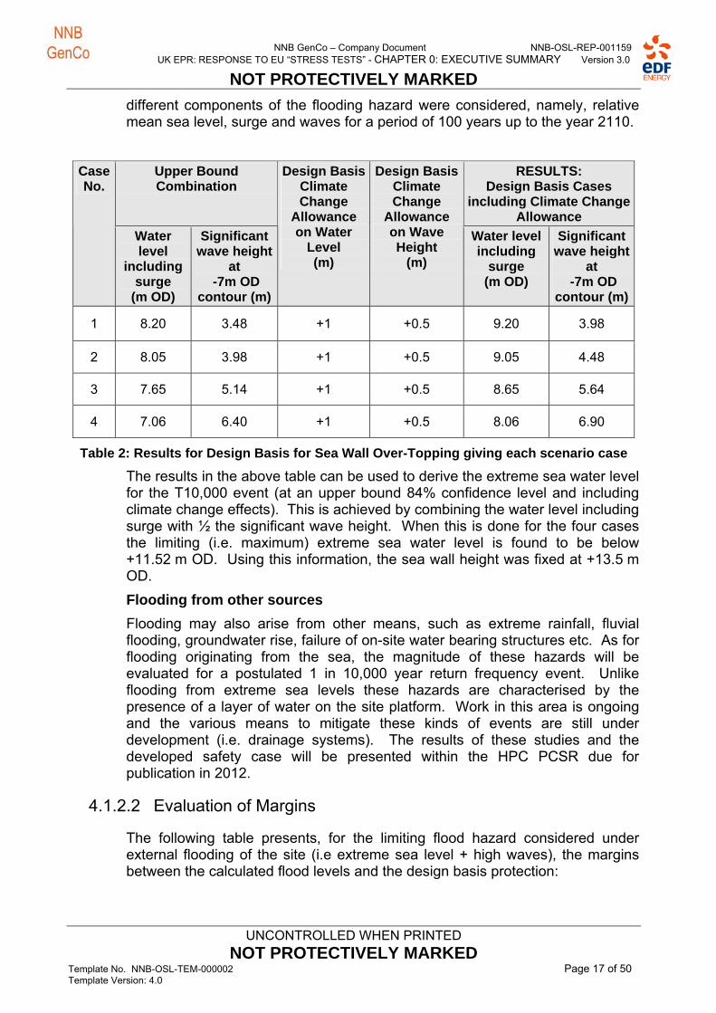
different components of the flooding hazard were considered, namely, relative mean sea level, surge and waves for a period of 100 years up to the year 2110.
Upper Bound Combination
RESULTS: Design Basis Cases
including Climate Change Allowance
Case No.
Water level
including surge
(m OD)
Significant wave height
at -7m OD
contour (m)
Design BasisClimate Change
Allowance on Water
Level (m)
Design BasisClimate Change
Allowance on Wave Height
(m)
Water level including
surge (m OD)
Significant wave height
at -7m OD
contour (m)
1 8.20 3.48 +1 +0.5 9.20 3.98
2 8.05 3.98 +1 +0.5 9.05 4.48
3 7.65 5.14 +1 +0.5 8.65 5.64
4 7.06 6.40 +1 +0.5 8.06 6.90
Table 2: Results for Design Basis for Sea Wall Over-Topping giving each scenario case
The results in the above table can be used to derive the extreme sea water level for the T10,000 event (at an upper bound 84% confidence level and including climate change effects). This is achieved by combining the water level including surge with ½ the significant wave height. When this is done for the four cases the limiting (i.e. maximum) extreme sea water level is found to be below +11.52 m OD. Using this information, the sea wall height was fixed at +13.5 m OD.
Flooding from other sources
Flooding may also arise from other means, such as extreme rainfall, fluvial flooding, groundwater rise, failure of on-site water bearing structures etc. As for flooding originating from the sea, the magnitude of these hazards will be evaluated for a postulated 1 in 10,000 year return frequency event. Unlike flooding from extreme sea levels these hazards are characterised by the presence of a layer of water on the site platform. Work in this area is ongoing and the various means to mitigate these kinds of events are still under development (i.e. drainage systems). The results of these studies and the developed safety case will be presented within the HPC PCSR due for publication in 2012.
4.1.2.2 Evaluation of Margins
The following table presents, for the limiting flood hazard considered under external flooding of the site (i.e extreme sea level + high waves), the margins between the calculated flood levels and the design basis protection:

NNB GenCo – Company Document NNB-OSL-REP-001159 UK EPR: RESPONSE TO EU “STRESS TESTS” - CHAPTER 0: EXECUTIVE SUMMARY Version 3.0
NOT PROTECTIVELY MARKED
UNCONTROLLED WHEN PRINTED
NOT PROTECTIVELY MARKED Template No. NNB-OSL-TEM-000002 Page 18 of 50 Template Version: 4.0
Design margin (in metres)
Flooding of the
pumping station
(total loss of heat sink)
Flooding of Electrical
Compounds.
(LOOP)
NB: materials are enhanced and
installed on the site +14.20m OD.
Flooding of the nuclear island.
(total loss of electrical supplies- both internal
and external)
Main Protection Provision
Extreme sea
flooding with
waves
2.58 m 2.68 m 2.58 m
Sea wall at +13.5 m OD with dedicated water drainage system against overtopping effect.
Setting of platform at +14 m OD
100 mm thresholds at doors for safety classified buildings.
Table 3: Margin between Calculated Flood Level and the Design Basis Protection
From the above table it can be seen that a margin in excess of 2.5 m exists between the maximum predicted water level and the flood protection provisions of the nuclear island and other safety related plant.
By way of comparison, a review of potential geological events that could result in tsunami waves reaching the UK coast has concluded that the maximum tsunami wave due to credible earth movements in the North Atlantic Ocean is below 2 m. This is comfortably bounded by the peak significant wave height listed in table 2 used to derive the extreme sea water level of +11.52 m OD.
It is concluded that the design basis for the proposed twin EPR power station at Hinkley Point C to flooding events originating from extreme sea conditions is confirmed to be appropriate in light of the events of Fukushima.
4.1.2.3 Identification of Cliff Edge Effects
The flood risk for HPC can come from two main phenomena, namely; rising sea level or the presence of a layer of water on the platform. The cliff-edge effect evaluation process identified three events potentially induced flooding:
Flooding causing loss of heat sink for HPC.
Flood situation causing a loss of offsite power (LOOP).
Flood situation causing a total loss of external and internal electrical sources associated with the possible loss of backup systems for reactors.

NNB GenCo – Company Document NNB-OSL-REP-001159 UK EPR: RESPONSE TO EU “STRESS TESTS” - CHAPTER 0: EXECUTIVE SUMMARY Version 3.0
NOT PROTECTIVELY MARKED
UNCONTROLLED WHEN PRINTED
NOT PROTECTIVELY MARKED Template No. NNB-OSL-TEM-000002 Page 19 of 50 Template Version: 4.0
Flooding causing a loss of safety classified equipment located in the outfall structure initiated by a presence of a layer of water on the platform.
These effects are illustrated using the following figure for HPC:
Figure 3: Schematic Representation of Flood Heights
Robustness of the plant to situations leading to a cliff edge effect
Loss of heat sink: The risk of loss of heat sink as a result of flooding caused by raising the sea level reference by 1 m does not represent a cliff edge when consideration is taken of the existing margins (>2.5 m). The sea level represented by a 1 m increase to the reference level represents an extremely infrequent event with a return frequency well below the 1 in 10,000 year period adopted for the external hazard assessment of the UK EPR design.
Loss of offsite power: As the design of the surface drainage is on going it is not possible to provide the detailed results of a quantitative robustness sensitivity assessment. The level of risk will be confirmed within the HPC PCSR and will recognise the learning from the events at Fukushima. Notwithstanding this, measures to improve the robustness of the site to LOOP arising from flooding can still be identified (see section 4.1.2.4).
Total loss of offsite and internal power: As the design of the surface drainage is on going it is not possible to provide the detailed results of a quantitative robustness sensitivity assessment. The level of risk will be confirmed within the HPC PCSR and will recognise the learning from the events at Fukushima. Notwithstanding this, measures to improve the robustness of the site to loss of all electrical power arising from flooding can still be identified (see section 4.1.2.4).
Flooding causing the loss of safety classified equipment in the outfall structure: Equipment of the ultimate cooling water system (UCWS) is located in the outfall structure. The access for this equipment is via a doorway at the
Extreme sea flooding level = 9.52 m OD
10.02 m OD
Sea Level
Drum screen washing system flooded in pumping station
14.1 m OD
SEC pump flooded => total loss of heat sink
Water entry to Diesel buildings.
+ 14.20 m OD Total loss of electrical supplies LOOP < compounds TA/TP/TS
Water level on site platform
+ 14 m OD Site platform
10.60 m OD Drum screen motor flooded in pumping station.

NNB GenCo – Company Document NNB-OSL-REP-001159 UK EPR: RESPONSE TO EU “STRESS TESTS” - CHAPTER 0: EXECUTIVE SUMMARY Version 3.0
NOT PROTECTIVELY MARKED
UNCONTROLLED WHEN PRINTED
NOT PROTECTIVELY MARKED Template No. NNB-OSL-TEM-000002 Page 20 of 50 Template Version: 4.0
platform level 14 m OD. Water above this value can enter the compartments housing the safety classified equipment of UCWS leading to them becoming flooded. If the pumping station is lost it would lead to a situation of total loss of heat sink.
4.1.2.4 Measures to be considered to improve robustness against flooding hazard
The following measures have been identified as potential means to increase the robustness of the plant to extreme flooding and will be given consideration by NNB GenCo;
Implementation of specific provisions to limit water ingress in to the pump house at the platform height.
Implementation of specific provisions to limit water ingress to the buildings located on the outfall slab.
Implementation of measures to protect the ultimate diesel generators and 12-hour batteries against flooding.
Measurement of the leak-tightness performance of security doors of buildings containing safety related plant when flood water is present on the platform of the nuclear island.
Furthermore, the current design basis for external flooding does not currently consider the seismic resistance of flood protection provisions (volumetric protection).
As a result, assessments to confirm the seismic resistance of the sealing elements (i.e. volumetric protection) of structures that house safety related plant will be carried out.
4.1.3 Extreme Weather
In addition to the extreme events of earthquake and flooding, the stress tests specification required consideration of “other extreme natural events”. In keeping with this, this section examines extreme weather conditions and their potential to affect the plant. Specifically the following effects are considered:
the possible direct effects of wind;
that of projectiles generated by extreme wind,
the effects of extreme air temperature (both high and low)
the effects of frazil ice,
the effects of hail,
the effects of lightning.
It should first be noted that the EPR design already takes into account the protection of facilities with regard to these hazards. This analysis is based on the safety arguments presented within the GDA PCSR. Since extreme values of weather conditions tend to be site dependent confirmation of the bounding

NNB GenCo – Company Document NNB-OSL-REP-001159 UK EPR: RESPONSE TO EU “STRESS TESTS” - CHAPTER 0: EXECUTIVE SUMMARY Version 3.0
NOT PROTECTIVELY MARKED
UNCONTROLLED WHEN PRINTED
NOT PROTECTIVELY MARKED Template No. NNB-OSL-TEM-000002 Page 21 of 50 Template Version: 4.0
nature will be complemented by further analyses as part of the development of the HPC site-specific PCSR.
4.1.3.1 Consideration of Design Basis
Wind and windborne projectiles
The design of buildings and structures that play a role with regard to nuclear safety takes into account the direct effects of extreme wind speeds. This is performed in accordance with the design standards. Safety related buildings are reinforced concrete structures designed to resist explosions which bound the conditions posed by extreme wind speeds. The consequences of impact damage caused by wind-borne missiles are bounded by the aircraft impact load cases considered in the design.
Extreme high air temperature
The extreme high air temperature for the Hinkley Point site has been calculated for the 10,000 year return period using observational data and the Extreme Value Analysis (EVA) methodology. The EVA has been completed by both the UK Met Office and the EDF R&D department; these assessments have used slightly different methodologies in order to provide further confidence in the results. The effects of climate change over the 21st century have also been incorporated into the EVA. The worst case results for the maximum air temperatures used within the design of HPC will be:
Extreme High Instantaneous Temperature = 44°C
Extreme High 12-hourly mean Temperature = 40°C
Extreme low air temperature
The air temperature values used within the design for the UK EPR, and associated with equipment requirements, are as follows:
Long duration temperature = -15°C permanent + wind (4 m/s)
Short duration temperature = -25 °C during 7 days
Prompt temperature = -35 °C during 6 hours
The extreme low air temperatures for the Hinkley Point site have been predicted by both the UK Met Office and the EDF R&D department using the Extreme Value Analysis methodology, as described for the extreme high air temperature section. The methodology uses the observed minimum air temperatures and provides a prediction of the low air temperature over a 10,000 year return period (the effects of climate change have not been incorporated due to the predicted increases in temperature contained within the regional climate models). The results from the EVA for the extreme low air temperature are shown below:
7-day mean temperature = -6.1°C
Daily mean temperature = -10.9°C
Extreme low instantaneous temperature = -12.3°C

NNB GenCo – Company Document NNB-OSL-REP-001159 UK EPR: RESPONSE TO EU “STRESS TESTS” - CHAPTER 0: EXECUTIVE SUMMARY Version 3.0
NOT PROTECTIVELY MARKED
UNCONTROLLED WHEN PRINTED
NOT PROTECTIVELY MARKED Template No. NNB-OSL-TEM-000002 Page 22 of 50 Template Version: 4.0
Frazil Ice
Under certain cold weather conditions the phenomenon of ‘frazil ice’ formation can occur in bodies of water. This frazil ice can constitute a blocking hazard for the cooling water intakes located (for HPC) in the Bristol Channel. In the extreme, the loss of water intake can lead to a loss of heat sink event occurring, although this can only occur if all four cooling water intakes are completely blocked. Analysis shows that whilst the frazil ice hazard needs to be taken into account, it will only lead to an event similar to flooding with loss of ultimate heat sink; therefore the assessment provided for flooding is considered to also be appropriate for the frazil ice hazard.
Hail
Hailstorms can cause on-site flooding to occur (though this bounded by heavy rainfall events) and direct impact damage to buildings and therefore constitute an extreme weather hazard. Hail has not been considered separately in the design of the UK EPR because it is a relatively rare meteorological phenomenon and highly localised in its effects. The majority of safety related equipment is located inside the robust buildings, which protects them from risk of damage by hail.
Lightning
Lightning has been taken into account in the design of the UK EPR as an extreme weather condition. Adequate provisions are implemented to ensure the safe functioning of systems and equipment that are necessary to maintain the plant in a safe condition and to prevent and limit radioactive releases. Lightning strikes with consequences of fire, internal explosion and rain of high intensity (storm) is considered as being bounded by the individual faults.
4.1.3.2 Evaluation of Margins
Wind and windborne projectiles
Experience feedback from the Hinkley Point site to high winds indicates no reports of significant structural damage to buildings for the existing nuclear plants sited there. Further useful experience can be gained from the response of the French fleet of PWRs to extreme storms (as occurred in December 1999 and described by Météo France as being of exceptional phenomenon for which there was no reference in the archives) sheds light on the robustness of the facilities to extreme winds associated with storms. These storms did not reveal any deterioration of the buildings constituting the nuclear island and the civil works of the cooling water pumphouse. In fact, since the systems and equipment to ensure safety functions are almost entirely within these buildings, the wind effects had no impact on the safety of nuclear power plants affected by the storm.
The projectiles observed on some nuclear sites during the storms of 1999 were of various types: gravel, stones, branches, twigs, broken glass, metal sheeting, and roof elements. The characteristics of these missiles are less damaging than the characteristics of projectiles included in the reference design of the UK EPR.
NNB GenCo – Company Document NNB-OSL-REP-001159 UK EPR: RESPONSE TO EU “STRESS TESTS” - CHAPTER 0: EXECUTIVE SUMMARY Version 3.0
NOT PROTECTIVELY MARKED
UNCONTROLLED WHEN PRINTED
NOT PROTECTIVELY MARKED Template No. NNB-OSL-TEM-000002 Page 23 of 50 Template Version: 4.0
The buildings on the nuclear island have been designed to ensure robust protection against an external explosion event; this effectively ensures the robustness of the buildings to extreme winds and windborne debris. Indeed, the explosion case forms the bounding envelope for the extreme wind load cases. For the UK EPR, there is a significant margin factor (>2) between the load case for external explosion and the load case for extreme wind. These buildings are:
The reactor building,
The fuel building,
The nuclear auxiliary building,
The four divisions of the safeguards auxiliary building and safeguard electrical rooms,
The diesel buildings and associated galleries.
In addition, the galleries that house the pipes carrying cooling water from the pumping station system consist mainly of infrastructure insensitive to the effects of wind (i.e. below ground). The only parts exposed to the wind are of reinforced concrete and thus have significant margins.
Extreme high air temperature
Design studies for the UK EPR show that the heating, ventilation and air-conditioning (HVAC) systems can readily be configured to provide cooling at the worst case temperatures, whilst maintaining design margins of between 6-10%. The equipment specifications for plant will also be set to ensure that all safety-related equipment can operate at a temperature of 50°C; this will ensure continued operation at temperatures in excess of the maximum predicted air temperature.
Extreme low air temperature
The design instantaneous low temperature is -35°C. This represents a margin of 20°C with respect to the equivalent instantaneous low air temperature predicted for the Hinkley Point site. The margins are 14°C and 9°C, respectively for short duration temperature and long duration temperature between the design low air temperatures and the predicted extreme low air temperature values.
Lightning
The UK EPR is designed to withstand lightning strikes. According to the treatment of lightning in the safety case, the risks associated with lightning are related to its direct effects and indirect effects. To protect against direct effects (i.e. when lightning directly affects a building) buildings and structures of the UK EPR have a minimum of level 1 lightning protection, against the direct effects of a lightning strike. The equipment protection is implemented through the use of a meshed cage. Safety classified equipment installed outside the buildings are identified and receive adequate protection against the direct effects of lightning. The indirect effects of lightning result in the creation of an electrical surge, by conduction or radiation that may disrupt the operation of sensitive equipment. Facility protection against indirect effects of lightning is provided under the

NNB GenCo – Company Document NNB-OSL-REP-001159 UK EPR: RESPONSE TO EU “STRESS TESTS” - CHAPTER 0: EXECUTIVE SUMMARY Version 3.0
NOT PROTECTIVELY MARKED
UNCONTROLLED WHEN PRINTED
NOT PROTECTIVELY MARKED Template No. NNB-OSL-TEM-000002 Page 24 of 50 Template Version: 4.0
standards for the protection of sensitive equipment against indirect effects of high frequency electromagnetic interference.
All of these provisions to protect against direct and indirect effects of lightning lead to a satisfactory level of protection of the UK EPR with regard to the lightning risk.
It is concluded that the design basis for the proposed twin EPR power station at Hinkley Point C to extreme weather conditions is confirmed to remain adequate in light of the events of Fukushima.
4.1.3.3 Identification of Cliff Edge Effects
Wind and windborne projectiles
For the UK EPR there is a margin of greater than two between the case load for external explosion and the case load for extreme wind. The design envelope specified for all buildings resistant to an external explosion is equivalent to stresses associated with extreme winds of much higher values than those calculated for the design basis wind load. For buildings not designed to the case load off-site explosion, the envisaged increases in wind speeds are unlikely to cause structural deterioration which would be detrimental to the nuclear safety of the unit. No cliff edge effect is therefore evident with respect to the buildings and equipment needed in situations of power loss, loss of heat sink and serious accidents.
Extreme high air temperature
The cliff edge effects from extreme high air temperature have been evaluated separately for the Nuclear Island plant and for the Balance of Plant. For the Nuclear Island the components which are sensitive to an increase of external temperature are mainly chillers and diesel engines. Concerning chillers, the cliff edge effect occurs at an external temperature of 47°C, which is 3°C above the predicted maximum air temperature. Concerning diesel engines, it has been considered that there are no cliff edge effects at temperatures up to 44°C, and the cliff-edge effects beyond this temperature will be identified following the selection of the diesel generators. For the Balance of Plant, to take into account the cliff edge effect, the maximal outside temperature which leads to an ambient temperature of 50°C has been evaluated in normal plant operating condition. This allows for a 6°C margin with the external temperature of 44°C.
4.1.3.4 Measures to be considered to Improve Robustness
No specific measures have been deemed necessary to improve the robustness of the plant to extreme weather.

NNB GenCo – Company Document NNB-OSL-REP-001159 UK EPR: RESPONSE TO EU “STRESS TESTS” - CHAPTER 0: EXECUTIVE SUMMARY Version 3.0
NOT PROTECTIVELY MARKED
UNCONTROLLED WHEN PRINTED
NOT PROTECTIVELY MARKED Template No. NNB-OSL-TEM-000002 Page 25 of 50 Template Version: 4.0
4.2 Loss of Safety Function Assessment
4.2.1 Loss of Off-site Power
The total loss of offsite power (LOOP) is an event within the design basis for the UK EPR. The successive loss of electrical supplies is considered as follows: loss of the main grid connection, failure of the plant systems to trip to “house-load” (where electrical supply for the unit would continue to be provided by the turbine generator) and loss of the external auxiliary grid connection.
Following loss of the different electrical supplies described above the four main diesel generators automatically start. The design includes consideration of a diesel generator being unavailable due to maintenance. An additional diesel generator is also assumed to fail to start in the corresponding design basis fault study.
4.2.1.1 Effect on Fuel in the Reactor
Following the LOOP the reactor is automatically tripped. However, the shutdown core still gives off heat, so-called ‘residual heat’. This residual heat needs to be removed from the nuclear core to prevent a rise in temperature and potential fuel damage.
Following the LOOP, the reactor coolant pumps (RCPs) lose their power supply and the primary coolant flow rapidly decreases. Per design a natural thermo-syphon circulation of primary coolant ensures residual heat removal to the secondary circuit coolant in the steam generators. The residual heat load decreases with time following automatic reactor shut-down.
On the secondary coolant circuit, the reactor trip causes the turbine to trip. The main feed water pumps (MFWPs), which normally feed the steam generators, lose their power supply. The emergency feed water system (EFWS) then takes over, powered by the emergency diesel generator supply.
The residual heat is removed in the steam generators due to the water circulation and evaporation, and then released via the atmospheric steam dump system valves.
After the start of the main diesel generators, an adequate electrical supply is available to take the unit to a safe shutdown state. A minimum of one operating main diesel generator is necessary to support the required safeguards plant.
Borated water is added to the primary circuit (to maintain reactor shutdown margin) throughout the cooling period, as the reactor coolant system (RCS) depressurises. Primary circuit depressurisation is performed with the pressuriser auxiliary spray line or by controlled opening of a pressuriser relief valve, if the spray line is not available.
The aim of these actions is to reach primary circuit conditions compatible with operation of the residual heat removal system (RHRS), as the preferred long-term heat removal method. These conditions are reached within approximately 8 hours post trip.
If the reactor was already shut-down and being cooled by the RHRS when the LOOP occurred, the aim would be to maintain it in that situation.
NNB GenCo – Company Document NNB-OSL-REP-001159 UK EPR: RESPONSE TO EU “STRESS TESTS” - CHAPTER 0: EXECUTIVE SUMMARY Version 3.0
NOT PROTECTIVELY MARKED
UNCONTROLLED WHEN PRINTED
NOT PROTECTIVELY MARKED Template No. NNB-OSL-TEM-000002 Page 26 of 50 Template Version: 4.0
The long term LOOP is safely mitigated by means of the functions and systems powered by the main diesel generators and there is no consequent challenge to the integrity of fuel present in the reactor.
As soon as an external power supply is restored (either main or auxiliary grid connection), it ends the LOOP situation and hence operation of main diesel generators is no longer necessary.
The bounding case considered is for a LOOP lasting for a maximum period of 15 days following an earthquake. The following considerations are therefore taken into account:
Considering maximum demand, the main diesel generator on-site fuel storage capacity is guaranteed for a minimum of 3 days per diesel generator. Re-supply from an external source may therefore be required within 3 days of the LOOP initiating event,
Lubricating oil reserves provide at least 10 days guaranteed on site storage capacity. Re-supply from an external source may therefore be required within the specified 15 day period,
Main diesel generator cooling water reserves are guaranteed for at least 11 days under maximum operating conditions. Re-supply may therefore be required within the specified 15 day period.
The UK EPR is designed to cope with a LOOP for at least 3 days, via operation of the emergency diesel generators. If the situation exceeds that duration and in the absence of external re-supply of fuel, lubricating oil and cooling water for the main diesel generators, the ultimate diesel generators provide an additional power supply for at least 24 hours.
Capability to provide necessary re-supply of the main diesel generators and maintain operation for at least 15 days following the LOOP event, will be ensured via the emergency arrangements for HPC, which have yet to be finalised.
4.2.1.2 Effect on Fuel in the Cooling Pool
The spent fuel pool is located in the fuel building, adjacent to the reactor building. Irradiated fuel assemblies are stored under water in racks located at the bottom of the pool, until their transfer to an Interim Spent Fuel Store (ISFS), which will provide long term fuel storage.
During refuelling outages, the whole core can be off-loaded to the spent fuel pool, via a transfer tube, which connects the spent fuel pool to the refuelling cavity in the reactor building (but is sealed at other times when fuel is not being transferred). Approximately ⅔ of the off-loaded irradiated fuel assemblies are re-loaded to the reactor during refuelling, together with new fuel assemblies. Irradiated fuel which has completed its useful life in the reactor, will be retained in the spent fuel pool.
Residual heat from stored fuel assemblies is removed by two identical main trains of the fuel pool cooling system (FPCS). Maximum heat load occurs with the core freshly un-loaded and requires both trains of FPCS to be operating. At other times, only one train of FPCS is required. Heat is rejected from the FPCS

NNB GenCo – Company Document NNB-OSL-REP-001159 UK EPR: RESPONSE TO EU “STRESS TESTS” - CHAPTER 0: EXECUTIVE SUMMARY Version 3.0
NOT PROTECTIVELY MARKED
UNCONTROLLED WHEN PRINTED
NOT PROTECTIVELY MARKED Template No. NNB-OSL-TEM-000002 Page 27 of 50 Template Version: 4.0
main trains to the component cooling water system (CCWS) and then to the essential service water system (ESWS).
The main FPCS trains, CCWS and ESWS trains have electrical supplies backed by the emergency diesel generators. A third diverse train of the FPCS is cooled by the containment heat removal system (CHRS), with its own heat sink via the ultimate cooling water system (UCWS), with two separate cooling water intake paths. The first is via the main cooling water intake and the second from the ESWS discharge channel.
Faults involving loss of electrical power or loss of the heat sink can lead to the loss of cooling of the spent fuel pool. Increase of water temperature leads to water evaporation and then to a gradual decrease of water level in the spent fuel pool. The objective is to maintain water coverage over the fuel assemblies to ensure, for all faults considered within the EPR design basis, the principal safety functions of residual heat removal, containment and reactivity control.
The UK EPR design makes provision for extra make-up to the spent fuel pool as follows:
demineralised water from a nuclear island demineralised water distribution system water tank.
fire fighting water supply system (JAC)
borated water from the reactor boron and water make-up system
This water make-up is required when the spent fuel pool level falls below a minimum threshold level, ensuring an adequate water depth above the irradiated fuel assemblies to provide radiation protection.
In faulted situations, the fuel building pressure could start to rise as a consequence of evaporation and general heating of the environment, as the spent fuel pool heats up. In the extreme, boiling could occur. In this case, an exhaust path can be manually opened which would ensure no effect on the fuel building integrity.
Considering bounding initial conditions (e.g. maximum residual heat load, maximum fuel pool operating temperature) as the LOOP occurs, the main FPCS trains, supported by the CCWS and ESWS are supplied by the emergency diesel generators with the possibility of an interconnection being required should a diesel generator be unavailable due to maintenance.
With electrical supplies provided by the emergency diesel generators, the cooling functions of the FPCS, CCWS and ESWS are supported and no challenge to fuel integrity ensues.
As indicated in section 4.2.1.1, the UK EPR is designed to cope with a LOOP for at least 3 days, via operation of the emergency diesel generators. If the situation exceeds that duration and in the absence of external re-supply of fuel, lube oil and cooling water for the main diesel generators, the ultimate diesel generators provide an additional power supply for at least 24 hours.

NNB GenCo – Company Document NNB-OSL-REP-001159 UK EPR: RESPONSE TO EU “STRESS TESTS” - CHAPTER 0: EXECUTIVE SUMMARY Version 3.0
NOT PROTECTIVELY MARKED
UNCONTROLLED WHEN PRINTED
NOT PROTECTIVELY MARKED Template No. NNB-OSL-TEM-000002 Page 28 of 50 Template Version: 4.0
Capability to provide necessary re-supply of the main diesel generators and maintain operation for at least 15 days following the LOOP event will be ensured via the emergency arrangements for HPC, which have yet to be finalised.
4.2.1.3 Effect on Fuel in the Interim Spent Fuel Store
The Interim Spent Fuel Store (ISFS) will provide wet pool storage for irradiated fuel after storage for about 10 years in the spent fuel pools of the two HPC units.
The design of the ISFS is conceptual at this stage, but the design processes will take into account the lessons arising from the earthquake and subsequent tsunami which seriously affected the Fukushima Daiichi nuclear plant in March 2011.
4.2.2 Total Loss of Electrical Power (on-site and off-site)
The loss of external power supplies and of the four main emergency diesel generators is considered to be a design extension condition (i.e. beyond the design basis). The event is considered to last for up to 24 hours before electrical supplies from the grid or the main emergency diesel generators are restored.
The electrical power supplies considered available in this situation are the two diverse and redundant ultimate diesel generators. The diversity in diesel generators lies in different equipment models, different output voltages, different fuel tanks as well as different support system designs (by virtue of the different ratings of the engines/generators). The choice of diesel generators takes into account the French PWR fleet feedback experience.
As with the loss of offsite power (LOOP) scenario described in section 4.2.1, the reactor will automatically trip. The reactor coolant pumps (RCPs) will stop. Residual heat will then be transferred from primary to secondary coolant by thermo-syphon (designed natural water circulation).
Thermal barrier cooling of the reactor coolant pumps will be lost and the chemical & volume control system (CVCS) charging pumps, which provide seal injection to the RCPs, will also be lost. The battery backed RCP stand still seal system (SSSS) will automatically initiate to prevent leakage of primary coolant.
Following loss of supplies to the main feedwater pumps, residual heat from the steam generators will be removed via the atmospheric steam dump valves.
The fault will be handled differently, depending on the initial plant operating state, as follows:
Whether initially operating at power, or shutdown but with the primary circuit intact and capable of being pressurised, the aim is to start the emergency feed water system (EFWS), perform partial cooling of the primary circuit via natural circulation through the steam generators and heat rejection via the atmospheric steam dump valves. If the primary circuit is not fully intact, the aim is to close any open vents and allow the system to heat up, with residual heat removal as described above.
NNB GenCo – Company Document NNB-OSL-REP-001159 UK EPR: RESPONSE TO EU “STRESS TESTS” - CHAPTER 0: EXECUTIVE SUMMARY Version 3.0
NOT PROTECTIVELY MARKED
UNCONTROLLED WHEN PRINTED
NOT PROTECTIVELY MARKED Template No. NNB-OSL-TEM-000002 Page 29 of 50 Template Version: 4.0
With the plant initially shutdown and primary circuit not intact, the principal plant operations consist of starting:
A low head safety injection system train, aligned to the in-containment refuelling water storage tank (IRWST), in order to compensate for the water lost due to steam generation from the primary coolant, released to containment,
One or two containment heat removal system (CHRS) and ultimate cooling water system (UCWS) trains to ensure that the residual heat is removed from the containment.
Before the start and synchronisation of the ultimate diesel generators, the four 2-hour batteries (supplying all four electrical divisions) and the two 12-hour batteries (supplying electrical divisions 1 and 4) provide the electrical supplies to the nuclear island. The ultimate diesel generators can operate for a period of at least 24 hours at full load. For all initial reactor states, in the case of a loss of offsite power and the four main emergency diesel generators, the plant is not at risk of fuel damage and external radioactive release. The 24 hour period should be adequate for the restoration of one of the alternate electrical supplies (main diesel generator or grid connection).
The situation of the loss of external power supplies, combined with the loss of the four main diesel generators and of the two ultimate diesel generators is a design extension condition (i.e. beyond the design basis but within the design capability of the plant) for the EPR. In this situation, it is considered that an electrical power supply (internal or external) will be made available 12 hours after the initiating event.
In order to improve the robustness of the site to a total loss of electrical supplies (LOOP + 4 main emergency diesel generators + 2 ultimate diesel generators). Alternative means to provide electrical power via a high-powered mobile diesel generator will be considered by NNB GenCo. The necessary fixed connection points will also be considered.
4.2.2.1 Effect on Fuel in the Reactor
Loss of all external and internal electrical supplies, with the plant initially operating at 100% power will lead to fuel deterioration within a few hours. The batteries provide a supply to very limited plant functions, indications and emergency lighting. It should be noted that the loss of all power supplies is considered very unlikely.
Ultimate Diesel Generator Considerations
For all initial reactor states, failure of the ultimate diesel generators (in addition to a LOOP and loss of all four emergency diesel generators) is a significant event beyond the design basis and deterioration of fuel in the reactor would start a few hours after the loss of all the electrical supplies. To avoid this, the ultimate diesel generators must remain in operation for the 24 hour mission period and thereafter either be replaced by an alternative power source (such as a mobile generator) or have their autonomy extended via supply of additional fuel and other consumables.

NNB GenCo – Company Document NNB-OSL-REP-001159 UK EPR: RESPONSE TO EU “STRESS TESTS” - CHAPTER 0: EXECUTIVE SUMMARY Version 3.0
NOT PROTECTIVELY MARKED
UNCONTROLLED WHEN PRINTED
NOT PROTECTIVELY MARKED Template No. NNB-OSL-TEM-000002 Page 30 of 50 Template Version: 4.0
In the eventuality where external diesel fuel supply is not possible, NNB GenCo will give consideration to the use of a mobile device to pump diesel fuel from the tanks of the main diesel generator tank to the ultimate diesel generators.
This measure would significantly increase the duration of the operation of the ultimate diesel generators, without external intervention. The mobile diesel pumping equipment will be stored in a place that will guarantee its availability while ensuring easy and efficient implementation.
If refuelling of the ultimate diesel generators is performed, additional lube oil supply needs to be considered after approximately 40 hours.
The emergency control organisation will ensure implementation of these measures.
Emergency Feed Water Reserve Considerations
If continuous residual heat removal is performed by the steam generators, supplied by the emergency feed water system (EFWS) pumps, the EFWS tanks would be emptied after approximately 2 days, if only one diesel generator is in operation. Re-supply is possible via the JAC pumps that can be powered by the ultimate diesel generators. With this contingency, the water supply capacity is extended to more than 7 days after the initiating event. Deterioration of fuel in the reactor would then be expected approximately 9 days after the initiating event.
In order to increase the autonomy of the secondary circuit cooling, , NNB GenCo will give consideration to the means required to allow the EFWS tanks to be re-supplied from the raw water storage system.
This measure would significantly increase the time available before the onset of fuel deterioration.
Emergency Feed Water System Diversity Considerations
The motive power for the pumps of the EFWS is via electric motors; two of the four pumps have motors supplied by the 10kV electrical supplies of safeguard divisions 2 and 3 and the remaining two are supplied by the 690V electrical supplies of safeguard divisions 1 and 4. Examination of the diversity, segregation and independence of the 10kV and 690V emergency electrical supplies (essentially the EDGs and UDGs) indicates high levels of diversity and segregation.
Notwithstanding the previous statement, NNB GenCo will give consideration to the provision of diverse means for providing emergency feed water to the steam generators.
This is in keeping with the practice at UK Nuclear Power Plants which either utilise steam-turbine driven emergency feed pumps (Sizewell B) or have an entirely separate tertiary feed system (diversity in pumps and motive power).

NNB GenCo – Company Document NNB-OSL-REP-001159 UK EPR: RESPONSE TO EU “STRESS TESTS” - CHAPTER 0: EXECUTIVE SUMMARY Version 3.0
NOT PROTECTIVELY MARKED
UNCONTROLLED WHEN PRINTED
NOT PROTECTIVELY MARKED Template No. NNB-OSL-TEM-000002 Page 31 of 50 Template Version: 4.0
4.2.2.2 Effect on Fuel in the Cooling Pool
During this scenario, cooling of the spent fuel pool by the two main FPCS trains stops.
The emergency electrical supply in this scenario is provided by the two ultimate diesel generators. The third diverse FPCS train (and supporting CHRS/UCWS trains) is powered by the electrical Division 1 ultimate diesel generator. Battery backed supplies do not support any cooling function for the spent fuel pool.
For initial reactor operating states when the ultimate diesel generator output is prioritised for residual heat removal from the primary coolant system/reactor building, the spent fuel pool may not be cooled by the third FPCS train. However, a fire fighting water supply system pump, with available tank capacities of 1000 m3 and 3000 m3 respectively, can be aligned to provide make-up water to the spent fuel pool. This makeup facility can be operated as required, depending on the demands on the ultimate diesel generators.
With fuel un-loaded from the reactor, spent fuel pool cooling is provided by the diverse third FPCS train.
In the absence of cooling, the spent fuel pool water would begin to heat up leading to increased evaporation and ultimately boiling. The fuel building ventilation dampers would be closed, to limit the spread of any steam generated from the fuel building to adjacent buildings. With a spent fuel pool temperature greater 50°C, the steam outlet from the fuel pit area (exhaust duct leading to the chimney of the Nuclear Auxiliary Building) will be opened, to prevent pressure build up in the fuel pit area. Access to the fuel building will still be possible despite the steam produced, subject to the provisions for personnel protection.
NNB GenCo will give consideration to enhancing the protection in this area by the addition of a passive or automatic device for releasing the steam pressure in the fuel pool hall.
When the spent fuel pool is cooled by the third FPCS train, the ultimate diesel generator can operate for more than one day without external intervention. Beyond that, without reactivation of an external electrical power source, or a main diesel generator, spent fuel pool cooling ceases.
The period of time before the uncovery of the fuel assemblies stored in the spent fuel pool is more than two days after loss of cooling. This is judged to give sufficient time for external intervention.
In the most conservative cases where only the ultimate diesel generator of electrical division 4 starts, or in the case where the two ultimate diesel generators are dedicated to the management of reactor building cooling, the spent fuel pool will not be cooled. As described above, water make-up can be provided by the fire fighting water supply system, while the ultimate diesel generator is operating (24 hour minimum capability). The volume of water necessary to compensate for the water loss during this period is 102 m3.
Once the ultimate diesel generators have run out of fuel, water losses can no longer be offset by make-up from the fire fighting system.

NNB GenCo – Company Document NNB-OSL-REP-001159 UK EPR: RESPONSE TO EU “STRESS TESTS” - CHAPTER 0: EXECUTIVE SUMMARY Version 3.0
NOT PROTECTIVELY MARKED
UNCONTROLLED WHEN PRINTED
NOT PROTECTIVELY MARKED Template No. NNB-OSL-TEM-000002 Page 32 of 50 Template Version: 4.0
The spent fuel pool water would boil at 100°C:
4 hours after loss of cooling (with the unloaded core present in the spent fuel pool). Subsequent fuel uncovery would occur after more than one day, without make-up1.
14.5 hours after loss of cooling (with the core assemblies loaded in the reactor vessel). Subsequent fuel uncovery would occur after more than four days, without make-up.
Both of these time periods are considered to be inside the time period for external intervention to be enacted as defined by the stress tests specification (see section 2.2.3).
In order to improve the robustness of the plant an ultimate water supply for the make-up of the spent fuel pools will be considered by NNB GenCo. The water supply will be provided by the raw water storage system and be pumped to the pools via an external connection to the fuel building.
The robustness of the instrumentation in the spent fuel pool (water temperature, water level, dose rate in the fuel pit area etc) under boiling conditions for long periods will be qualified. In addition, NNB GenCo will give consideration to the addition of this essential instrumentation to the 12-hour battery backed severe accident I&C scheme.
The need for a high-power electrical source three days after the initiating event has been identified to ensure the habitability (breathable atmosphere) of the main control room (see 4.3). This would also enable the operation of a FPCS train for cooling, or to carry out water make-up via the fire fighting system tanks. Options will be considered to ensure that an external mobile power source can be connected. This would also allow the situation in the fuel building to be managed in parallel with the situation in the reactor building.
Capability to provide the necessary re-supply of the ultimate diesel generators and maintain operation beyond 24 hours following the LOOP and loss of main diesel generators will be ensured via the emergency arrangements for HPC, which have yet to be finalised. Extending the operational period of the ultimate diesel generator would extend the duration of the emergency electric supply for the third FPCS train and/or extend the period of time for extra water make-up from the fire fighting system.
Additional issues pertaining to a loss of electrical supplies to the fuel building are fuel assembly handling and hydrogen gas build-up via radiolysis of the pool water. Any fuel handling in progress at the time of the loss of electrical supplies would be stopped and the fuel assemblies being handled would be placed in a safe storage position.
Consideration will be given by NNB GenCo to the additional equipment and organisational measures required to achieve the safe positioning of a fuel assembly being handled during a loss of electrical supplies.
1 Severe fuel damage will occur shortly after fuel becomes uncovered (the exact time being dependent on the fuel rating, burn-up and the number of days cooled)
NNB GenCo – Company Document NNB-OSL-REP-001159 UK EPR: RESPONSE TO EU “STRESS TESTS” - CHAPTER 0: EXECUTIVE SUMMARY Version 3.0
NOT PROTECTIVELY MARKED
UNCONTROLLED WHEN PRINTED
NOT PROTECTIVELY MARKED Template No. NNB-OSL-TEM-000002 Page 33 of 50 Template Version: 4.0
Irradiated fuel assemblies in the spent fuel pool can produce hydrogen by water radiolysis. The normal ventilation provided by the fuel building ventilation system will be ineffective following the loss of offsite power.
Analysis will be undertaken to assess the potential risk of hydrogen gas build-up due to water radiolysis in the absence of ventilation. NNB GenCo will then review options for equipment to be installed to prevent the potential risk of explosion due to hydrogen gas build-up and (if required) will include this in the Hinkley Point C design.
The radiolysis study detailed above will be complemented by a further study into the prevention and mitigation of hydrogen gas accumulation in the fuel building.
4.2.2.3 Effect on Fuel in the Interim Spent Fuel Store
The Interim Spent Fuel Store (ISFS) will provide wet pool storage for irradiated fuel after storage for about 10 years in the spent fuel pools of the two HPC units.
The design of the ISFS is conceptual at this stage, but the design processes will take into account the lessons arising from the earthquake and subsequent tsunami which seriously affected the Fukushima Daiichi nuclear plant in March 2011.
4.2.3 Loss of Ultimate Heat Sink
For the proposed HPC units, residual heat is transferred to the natural heat sink via the component cooling water system (CCWS) and the essential service water system (ESWS). These systems act as the heat sink in normal operation, when the reactor is shut-down, when the core is unloaded and in some faulted/accident situations. In case of faults where CCWS and/or ESWS function is lost, or to minimise the consequences of other faults, cooling is performed by the ultimate cooling water system (UCWS) via the containment heat removal system (CHRS). Four ESWS trains and two UCWS trains are provided, with their respective pumps located in the main pumping station, but are physically segregated. Coarse and fine filtration is provided for respective intake paths.
An interconnected system enables feed to one train by another downstream of the filtration. The same system is also connected to the discharge pond by the diversification route which enables feeding of the associated coolant train (ESWS/UCWS) if the main heat sink is unavailable.
The loss of the unit main heat sink is a design basis fault. The total loss of heat sink causes inoperability of the feed-water plant, the ESWS, the CCWS (the loss of ESWS causes a gradual warming of the CCWS which eventually will no longer provide adequate auxiliary cooling), the residual heat removal system (RHRS), the reactor coolant pumps (RCP) and the safety injection system (except for low pressure safety injection on trains 1 and 4).

NNB GenCo – Company Document NNB-OSL-REP-001159 UK EPR: RESPONSE TO EU “STRESS TESTS” - CHAPTER 0: EXECUTIVE SUMMARY Version 3.0
NOT PROTECTIVELY MARKED
UNCONTROLLED WHEN PRINTED
NOT PROTECTIVELY MARKED Template No. NNB-OSL-TEM-000002 Page 34 of 50 Template Version: 4.0
It should be noted that the plant operators can connect an ESWS train to the discharge pond using the diversification route before the situation described below evolves. The required operations differ according to the initial state of the unit.
With the primary circuit intact and capable of being pressurised, the aim of the operation is to perform cooling of the primary circuit via thermo-syphon through the steam generators; steam discharge via the secondary circuit atmospheric steam dump valves and re-supply of the EFWS tanks from the fire fighting water supply system tanks. If the primary circuit is not fully intact, the aim would be to close any open vents to allow the primary system to heat up and re-pressurise.
If the primary circuit is not intact, the operation consists of putting in to service: At least one low head safety injection (LHSI) train aligned to the in
containment refuelling water storage tank (IRWST) in order to compensate for primary coolant water lost as steam. The pumps of trains 1 and 4 of the LHSI have diverse (air) cooling derived from the safety chilled water system (SCWS).
One or two CHRS and UCWS trains to support containment residual heat removal.
4.2.3.1 Effect on Fuel in the Reactor
The EPR design makes provision for the re-supply of the EFWS from the fire fighting water supply system for several days. The fire fighting water system is composed of two concrete tanks (1000 m3 and 3000 m3 capacity), to which the EFWS re-supply pumps can be aligned.
With primary circuit intact or partially intact
The loss of external power supplies and of the 4 main diesel generators event bounds this event (per section 4.2.2).
If the unit is initially operating at 100% power, the EFWS tanks will be emptied approximately 2 days after event initiation. The re-supply of these tanks from the fire fighting water supply provides a total water storage capacity for more than 7 days after the initiating event, after which time these tanks will eventually be exhausted. Under these conditions, fuel deterioration is predicted to start about 9 days after the initiating event.
However, once the fire fighting water system tanks are empty, re-supply of the EFWS tanks from the raw water storage system is envisaged. This will increase the unit residual heat removal capability for several more days, allowing further time for external support to be enacted, if required.
With primary circuit not intact
The fault study associated with this scenario shows that the core will remain covered for several days and residual heat removal is guaranteed for the long term. No external action is envisaged to avoid fuel deterioration.

NNB GenCo – Company Document NNB-OSL-REP-001159 UK EPR: RESPONSE TO EU “STRESS TESTS” - CHAPTER 0: EXECUTIVE SUMMARY Version 3.0
NOT PROTECTIVELY MARKED
UNCONTROLLED WHEN PRINTED
NOT PROTECTIVELY MARKED Template No. NNB-OSL-TEM-000002 Page 35 of 50 Template Version: 4.0
4.2.3.2 Effect on Fuel in the Cooling Pool
Loss of Main Cooling System
With the primary circuit not intact, two CHRS trains may be required to support heat removal in the reactor containment as a priority. The spent fuel pool may not therefore be cooled via the diverse third FPCS train. Water make-up to the spent fuel pool via the fire fighting system (two tanks 1000 m3 and 3000 m3 capacity) will prevent fuel assembly uncovery.
In other plant states, the third FPCS train cooled by CHRS/UCWS can be started to cool the spent fuel pool, aligned to the diverse heat sink.
Extra water make-up by the nuclear island demineralised water distribution system or reactor boron and water make-up system (RBWMS) would be available but are not claimed.
With the primary circuit not intact, make-up from the fire fighting water supply system can maintain the water level in the spent fuel pool for:
about four days with the tank of 1000 m3 capacity
more than ten days with the tank of 3000 m3 capacity
The period of time before the uncovery of fuel assemblies stored in the spent fuel pool is about 18 days. This period is considered to be well inside the time period for external intervention to be enacted as defined by the stress tests specification (see section 2.2.3).
In other states, the third (diverse) FPCS train provides cooling of the spent fuel pool.
Loss of Main and Diverse Cooling Systems
In this scenario, all three FPCS cooling trains are lost due to the loss of CCWS/ESWS and CHRS/UCWS trains. This scenario is a beyond design basis fault for HPC. The evidence presented in the following section about this scenario therefore relates to additional consideration following the Fukushima events.
For the scenario of loss of the main and diverse cooling systems, provisions for extra water make-up by the nuclear island demineralised water distribution system or RBWMS would be available but are not claimed in this analysis.
With the primary circuit intact, the fire fighting supply tank of 3000 m3 capacity is dedicated to the re-supply the EFWS tanks. The smaller tank provides about four days of make-up to the spent fuel pool before uncovery of fuel. This period is considered adequate for external intervention to be enacted.
With primary circuit not intact, fire fighting supply make-up can maintain the water level in the pool for:
about four days with the 1000 m3 tank
more than ten days with the 3000 m3 tank
Hence the time period before the uncovery of fuel assemblies stored in the spent fuel pool is about 18 days. This is considered to be well inside the time period for external intervention to be enacted as defined by the stress tests specification (see section 2.2.3).
NNB GenCo – Company Document NNB-OSL-REP-001159 UK EPR: RESPONSE TO EU “STRESS TESTS” - CHAPTER 0: EXECUTIVE SUMMARY Version 3.0
NOT PROTECTIVELY MARKED
UNCONTROLLED WHEN PRINTED
NOT PROTECTIVELY MARKED Template No. NNB-OSL-TEM-000002 Page 36 of 50 Template Version: 4.0
With fuel freshly unloaded from the core, the fire fighting supply make-up can maintain the water level in the spent fuel pool for:
more than a day with the 1000 m3 tank
over three days with the 3000 m3 tank
The period before the uncovery of fuel assemblies stored in the spent fuel pool is therefore about 5 days. This is inside the time period for external intervention to be enacted as defined by the stress tests specification (see section 2.2.3).
4.2.3.3 Effect on Fuel in the Interim Spent Fuel Store
The Interim Spent Fuel Store (ISFS) will provide wet pool storage for irradiated fuel after storage for about 10 years in the spent fuel pools of the two HPC units.
The design of the ISFS is conceptual at this stage, but the design processes will take into account the lessons arising from the earthquake and subsequent tsunami which seriously affected the Fukushima Daiichi nuclear plant in March 2011.
4.2.4 Combined Total Loss of Power and Ultimate Heat Sink
In this scenario, the main heat sink is lost together with the external electrical power supplies and the main diesel generators.
This scenario is outside the current design basis. The following reflects particular consideration of the Fukushima accident.
Given that the component cooling water system (CCWS) pumps are powered from the main diesel generator backed switchgear, the total loss of the electrical supplies effectively causes the total loss of the main heat sink.
Following a LOOP (as a consequence of an earthquake), combined with failure of the main diesel generators to start, the ultimate diesel generators will be available.
The ultimate cooling water system (UCWS) combined with the containment heat removal system (CHRS) will be available to remove residual heat from the reactor building (in plant states where the primary circuit is not intact). The emergency feedwater system will be available to remove residual heat, via thermo-syphon through the steam generators, in plant states where the primary circuit is intact and can be pressurised.
If the ultimate diesel generators are also lost, the plant position is still bounded by the considerations above (section 4.2.2) relating to the loss of all external and internal electrical supplies. The measures described above to prevent fuel deterioration (whether in the reactor or spent fuel pool) and potentially improve the robustness of the plant are still applicable to this scenario.
With respect to flooding specifically, all the emergency plant required to cope with the current design basis flood will be available as they are located in buildings protected against external flooding.

NNB GenCo – Company Document NNB-OSL-REP-001159 UK EPR: RESPONSE TO EU “STRESS TESTS” - CHAPTER 0: EXECUTIVE SUMMARY Version 3.0
NOT PROTECTIVELY MARKED
UNCONTROLLED WHEN PRINTED
NOT PROTECTIVELY MARKED Template No. NNB-OSL-TEM-000002 Page 37 of 50 Template Version: 4.0
4.2.4.1 Effect on Fuel in the Reactor
The effect on the fuel in the reactor is as described in section 4.2.2.1.
4.2.4.2 Effect on Fuel in the Cooling Pool
The effect on the fuel in the cooling pond is as described in section 4.2.2.2.
4.2.4.3 Effect on Fuel in the Interim Spent Fuel Store
The situation with regard to the ISFS is as described in section 4.2.2.3
4.2.5 Twin Unit Site Considerations
4.2.5.1 Cross-connection of Services
In the interests of achieving high levels of reliability the design of the EPR provides little in the way of cross-connection between units for sites containing multiple units. In the case of the proposed Hinkley Point C power station the only notable cross connections between the two units are as follows;
At the 400kV level of the electrical power distribution system
At the heat sink forebays via two onshore link tunnels having an internal diameter of 1.8m
The presence of the interconnection detailed above has little bearing on the stress tests assessment due to the fact that the cross connection either do not involve safety related systems (i.e. 400kV cross connection) or the means of cross connection are not intended for safety related usage and hence cannot be guaranteed to be available in the event of a severe accident scenario (i.e. heat sink forebay link tunnels). In any event the magnitudes of the severe events considered by the stress tests are such that both units would be expected to be affected simultaneously and to the same extent, thereby obviating any opportunity to utilise any cross-connections which might exist.
4.2.5.2 Shared Services
By design there are no safety related services or plant shared between EPR units present on multi-unit sites, except the ISFS which is discussed elsewhere in this report. However, the raw water storage system is proposed as a means to provide extended water supplies in the event of severe accident scenarios. Water supply would be required for the following;
Re-supply of the EFWS tanks
Spent fuel pool make-up
Reactor building containment spray
For the proposed Hinkley Point C power station a single townswater reservoir is proposed for the raw water storage system and this has been appropriately sized for a twin unit site.

NNB GenCo – Company Document NNB-OSL-REP-001159 UK EPR: RESPONSE TO EU “STRESS TESTS” - CHAPTER 0: EXECUTIVE SUMMARY Version 3.0
NOT PROTECTIVELY MARKED
UNCONTROLLED WHEN PRINTED
NOT PROTECTIVELY MARKED Template No. NNB-OSL-TEM-000002 Page 38 of 50 Template Version: 4.0
4.3 Severe Accident Assessment
4.3.1 Licensee Organisation to Manage Severe Accidents
The Licensee organisation is expected to have the necessary arrangements, resources and infrastructure to face any situation, whether incidental, accidental or a serious event. There is recognition that the organisational requirements for a serious accident will be different to those of normal operation, hence there will be procedures and processes in place to re-organise as soon as possible following a serious accident. This will allow the event to be dealt with in a more efficient way and maintain the safety of staff as far as possible.
Those already working on site when the event occurs will be prepared for the necessary short term actions. The operating crew will be assisted by a team onsite in the Emergency Control Centre which will be set up as soon as possible. Within an hour the off-site support centre will be set up at a location away from the site. The off-site support centre will provide technical support to the teams on site.
The events at Fukushima have highlighted the need to account for the psychological impact of such a severe event on personnel. Therefore counselling will be available for staff caught in the event which could have a significant impact on the local community (which includes the families/friends of many staff).
The means used in normal operation for control of radiological conditions and radiological risks to people would still be operational but adapted to conditions which may occur during a serious accident. The usual radiological protection procedures will also be in place but it is possible that interventions in radiologically hostile conditions (over and above normal exposures) might be required for preservation of life. Stocks of iodine tablets are maintained in the event of a radiological emergency.
The Licensee arrangements for emergency response will be set up in advance of when the site becomes operational, with all teams and crews suitably trained. Emergency exercises will be carried out regularly to allow operators and technical support to build up the necessary skills to be confident they can manage in a crisis situation. It also aids in understanding some of the events that can occur and the actions required to remedy them. These actions will be laid out in procedures and technical specifications to ensure a rapid and robust response. The experience from the events of Fukushima indicates that severe accident contingency arrangements need to cover a wide range of events including those that are considered to be clearly beyond the design basis of the plant.
NNB GenCo will ensure that severe accident management procedures will provide contingencies for events which exceed both design basis and design extension conditions.
The EPR design has many advanced safety systems for the mitigation of severe accidents such as the corium spreading area and passive hydrogen recombiners. However, there are severe accident situations where mobile equipment might need to be brought to site. This would primarily include

NNB GenCo – Company Document NNB-OSL-REP-001159 UK EPR: RESPONSE TO EU “STRESS TESTS” - CHAPTER 0: EXECUTIVE SUMMARY Version 3.0
NOT PROTECTIVELY MARKED
UNCONTROLLED WHEN PRINTED
NOT PROTECTIVELY MARKED Template No. NNB-OSL-TEM-000002 Page 39 of 50 Template Version: 4.0
generators and pumps in the unlikely case of total loss of electrical supplies and/or cooling systems. The proposal being considered for HPC is to either have all necessary equipment near the edge of the site in a “hardened facility” or to have emergency mobile devices which are lightweight enough to be brought to the site. Through the EDF group NNB GenCo has access to equipment that will allow for remote inspection and some remote work on the site in case of high local dose rate.
In the case of total loss of electrical power, backup lighting for the main control room and the provision of sufficient information in a severe accident is provided by batteries. A breathable atmosphere for the operating crew is ensured for a period of 3 days. A total loss of electrical power would also eventually impact upon the communication systems used to coordinate emergency response activities around the site in the event of a severe accident.
In order to improve the robustness of communication in the event of a severe accident involving loss of all electrical supplies NNB GenCo will give consideration to the installation of a suitable network of communication devices on the site (i.e. sound-powered telephones).
4.3.2 Loss of Containment Integrity
Severe accidents have been considered during the design phase for the EPR and many features have been included to mitigate their consequences. Maintaining containment integrity is one of the primary means of mitigation. These mitigating features have been re-examined considering the most extreme stresses that they might be subjected to. These have proved to be adequate in almost all cases, however the stress tests have shown where it is worth considering some additional features that may provide further benefit.
The EPR is designed to preclude the risk of a high pressure core melt. It is prevented by the depressurisation of the primary circuit. There are three Pressuriser Safety Relief Valves and further diverse means of depressurisation via the severe accident valves. These valves are powered by the 12-hour batteries.
As power supply to these valves is vital to prevent a cliff edge effect, extension of the duration of power supply of the essential functions from the 12-hour batteries via additional stationary and/or mobile power sources is being considered by NNB GenCo.
However this lower pressure does not prevent damage to the fuel and during an extreme event it is possible that loss of cooling may take place. In this eventuality there might be significant fuel damage but, for the EPR, containment is not compromised.
As the fuel heats up beyond normal limits hydrogen is produced due to reaction of the fuel cladding with steam and the interaction of molten fuel with concrete in the case of fuel melt following a breach of the pressure vessel. This presents the risk of hydrogen explosion which could rupture containment. In order to limit the creation of an explosive atmosphere passive autocatalytic hydrogen recombiners have been incorporated into the containment which can function even in the highly degraded situation of a severe accident. Studies have shown
NNB GenCo – Company Document NNB-OSL-REP-001159 UK EPR: RESPONSE TO EU “STRESS TESTS” - CHAPTER 0: EXECUTIVE SUMMARY Version 3.0
NOT PROTECTIVELY MARKED
UNCONTROLLED WHEN PRINTED
NOT PROTECTIVELY MARKED Template No. NNB-OSL-TEM-000002 Page 40 of 50 Template Version: 4.0
the use of these (and design features that would limit hydrogen production) will be sufficient to prevent a hydrogen explosion.
The Containment Heat Removal System will spray water from the top of containment in a severe accident. This cools the atmosphere inside containment and the water that condenses is collected at the bottom of containment in order to be used again for spraying. This ensures that heat can be removed from containment and consequently over pressurisation is prevented. The Containment Heat Removal System is separated into two redundant trains, is backed by diesels/batteries and has diversity in its heat sink. In the unlikely event of a protracted loss of power supplies an alternative means of containment heat removal would be required after two days.
Hence provision of a mobile pump for introduction of water (from the raw water storage system) in to the reactor building through the containment heat removal system spray nozzles will be considered by NNB GenCo. This would also require the addition of a remote operation capability to valves for introduction of extra water.
The approach taken by the EPR design to over-pressurisation of the reactor containment is to provide sufficient cooling via the CHRS thereby obviating the requirement for an engineered filtered venting capability.
However, NNB GenCo will perform a study and investigate the provision of further systems or equipment to control containment over-pressure in severe accident conditions.
This approach is in keeping with common practice for civil PWRs worldwide which provide containment venting in a severe accident situation as part of their design.
In the case of fuel melt the parameters affecting the nuclear chain reaction can be changed, such as fuel geometry. Hence there is a possibility that the chain reaction can be restarted. Studies have shown however that even in the most conservative of cases re-criticality will not occur.
Even in the design extension conditions considered within the safety case, back-up power is maintained which allows for the Safety Injection and Containment Heat Removal Systems to continue to provide some cooling and hence prevent core melt. It is only in the highest category of severe events that significant core melt could occur and lead to a rupture of the pressure vessel. The EPR design includes a corium spreading area for such an eventuality. This allows the molten core to spread out and passive flooding valves are opened from the water storage tank, located within containment, allowing for the cooling of the molten corium.
For the operators to take the correct action to maintain containment integrity it is necessary to maintain the instrumentation and control systems.
The performance of the essential instrumentation required in the reactor building, in particular the sensors for measuring containment pressure and dose rate, will be qualified for the conditions it is likely to encounter under severe accident conditions.

NNB GenCo – Company Document NNB-OSL-REP-001159 UK EPR: RESPONSE TO EU “STRESS TESTS” - CHAPTER 0: EXECUTIVE SUMMARY Version 3.0
NOT PROTECTIVELY MARKED
UNCONTROLLED WHEN PRINTED
NOT PROTECTIVELY MARKED Template No. NNB-OSL-TEM-000002 Page 41 of 50 Template Version: 4.0
In addition the leak tightness performance of the containment penetrations (the penetrations themselves and their isolation valves) will be qualified for the conditions they are likely to encounter under severe accident conditions.
The instrumentation and control equipment are automatically supplied by the 12-hour batteries in the event of a loss of the grid and back up generators. However, the events at Fukushima showed that in an extreme situation power may not be restored for some time.
Provision of means for re-powering the dedicated Severe Accident Instrumentation and Control equipment will be considered by NNB GenCo.
In order to improve plant flexibility in the event of a severe accident NNB GenCo will give consideration to the means necessary to provide cross connection between the individual trains of safety systems. The safety systems to be considered include both electrical and fluid systems.
At this time it is envisaged that the above measure would be implemented via the provision of suitable connection points that could be utilised on the timescales associated with the development of a severe accident rather than being permanent installations.
Other areas of emergency equipment which have been considered as part of the post-Fukushima event assessments include the pumps of the fire fighting system, which under the EPR design are driven exclusively by electric motors.
NNB GenCo will give consideration to the incorporation of diesel driven fire pumps in addition to the current electrically driven pumps as a means to introducing diversity in site fire fighting capability.
The use of diesel driven fire pumps is considered normal practice in the UK.
4.3.3 Loss of Spent Fuel Pool Cooling
The water in the spent fuel pools fulfils the dual functions of protecting personnel against the radiation of the spent fuel and providing the means to cool this fuel. The analysis of the spent fuel pool cooling has shown that the autonomy of the system can, in all situations, ensure a water level higher than the top of the fuel assemblies within a timeframe compatible with any external support that would need to be implemented. However, the stress test examines the deterministic situation resulting from the loss of the water in the pool and the accompanying drop in level.
Once cooling is lost, water temperature starts to rise leading to increased evaporation until boiling starts to occur at 100°C. It will become necessary to provide a make-up water supply to the pools before the fuel is uncovered and damage can occur. There are checks on the cooling systems of the fuel pools made every 6 hours which would give early indication of any loss of cooling function. Action can then start to be taken before any problems have occurred. The actions would involve the operating crews aligning fuel pond remote make-up supply. However, assuming that the fuel does become uncovered (under the principles of the stress test) then operator actions would be prevented due to

NNB GenCo – Company Document NNB-OSL-REP-001159 UK EPR: RESPONSE TO EU “STRESS TESTS” - CHAPTER 0: EXECUTIVE SUMMARY Version 3.0
NOT PROTECTIVELY MARKED
UNCONTROLLED WHEN PRINTED
NOT PROTECTIVELY MARKED Template No. NNB-OSL-TEM-000002 Page 42 of 50 Template Version: 4.0
excessively high radiation levels. The measure already mentioned in section 4.2.2.2 (i.e. provision of an external water injection point on the fuel building) will help mitigate this situation. The concrete walls of the building would provide protection to staff working in adjacent rooms even in the event of the fuel becoming uncovered.
4.3.4 Loss of Interim Spent Fuel Store Cooling
For HPC the interim Spent Fuel Store is still at the conceptual design stage. Full cognisance of the experiences from the Fukushima event will be taken into account during the design process.

NNB GenCo – Company Document NNB-OSL-REP-001159 UK EPR: RESPONSE TO EU “STRESS TESTS” - CHAPTER 0: EXECUTIVE SUMMARY Version 3.0
NOT PROTECTIVELY MARKED
UNCONTROLLED WHEN PRINTED
NOT PROTECTIVELY MARKED Template No. NNB-OSL-TEM-000002 Page 43 of 50 Template Version: 4.0
5 FURTHER ASSESSMENTS OF THE UK EPR DESIGN
The stress tests are not the only assessments carried out for the UK EPR design in light of the events that occurred at Fukushima in March 2011. Assessments have been carried out or are being carried out as follows;
Technical reviews (carried out by both NNB GenCo and EDF SA),
In response to the ONR Chief Inspector’s Report,
As a specific GDA issue.
5.1 Technical Reviews Shortly after the events at Fukushima the NNB GenCo Director of Operations, Safety and Licensing requested the UK EPR Project Special Advisor to form a team to lead the internal review of the UK EPR design. Terms of reference were drawn up for the review with membership drawn both from inside NNB GenCo and EDF SA. The team reviewed the event (based on the information available at the time) against its knowledge of the UK EPR design. Issues identified as part of the review were formulated as 53 questions for the Architect Engineer (EDF DIN) to provide answers to. Answers to all 53 questions have now been provided by the AE. These responses have been analysed by the NNB GenCo team and this improved understanding has benefited the technical review of the UK EPR and provides some measure of internal peer review to the stress tests assessments reported within this document.
In addition to the NNB GenCo Technical Review of the UK EPR design a Technical Review of the FA3 NPP, which is currently under construction in France, was carried out by EDF SA. The results from this assessment are applicable to the UK EPR design due to the very similar design of the FA3 plant (details pertaining to the heat sink and adoption of a single unit design are the major differences). The initial work stemmed from a relatively prompt request from the French Nuclear Regulator (ASN) in April for EDF SA to assess its fleet of PWRs against the WENRA assessment specification. This led the AE to assess the EPR design in the areas of loss of ultimate heat sink, loss of off-site and on-site electrical supplies, the hazards of external flooding and earthquakes, loss of cooling to the spent fuel pool and severe accidents. EDF and AREVA identified a number of scenarios considered to bound the requirements of the WENRA specification. The work was divided in to two parts; understanding the validity and robustness of the design basis and then identifying potential enhancements that could be made to the design to either improve its robustness or move it further away from any identified ‘cliff edge’ effects. The results from this work have been used in various technical reviews and will also be reported as part of the GDA issue resolution plan (see later).
To facilitate NNB GenCo involvement in the assessment work there have been direct discussions between NNB Design Authority and the Architect Engineer on a number of topics including diversity and segregation of emergency diesel generators, electrical switchboards and emergency feedwater systems. In a number of cases the meetings have been used to make comparisons between the UK EPR design and Sizewell B.

NNB GenCo – Company Document NNB-OSL-REP-001159 UK EPR: RESPONSE TO EU “STRESS TESTS” - CHAPTER 0: EXECUTIVE SUMMARY Version 3.0
NOT PROTECTIVELY MARKED
UNCONTROLLED WHEN PRINTED
NOT PROTECTIVELY MARKED Template No. NNB-OSL-TEM-000002 Page 44 of 50 Template Version: 4.0
5.2 NNB Response to the ONR Chief Inspector’s Report into the Fukushima Event NNB GenCo, as part of EDF Energy, has responded to the ONR Chief Inspector’s Report on the ‘Japanese Earthquake and Tsunami: Implications for the UK Nuclear Industry’. NNB GenCo made a response during the production of the report and an initial response to the recommendations in the interim report in June together with a progress report in July. The Final Report from the ONR Chief Inspector was published in mid-October 2011.
NNB GenCo is now formulating the detailed response plans to the recommendations made in the Chief Inspector’s Report. The work in formulating these plans draws on the analyses and reports from the Architect Engineer produced in response to the WENRA specification. In addition to those recommendations associated with the analysis described above, NNB GenCo will also be responding to the recommendations associated with the broader issues of openness, transparency and emergency planning. In these areas the NNB GenCo responses will be broadly consistent with those made by EDF Energy Nuclear Generation.
5.3 Generic Design Assessment Issue Following the events at Fukushima a specific Issue (CC-03) relating to the learning from the event was raised by the regulators for the requesting parties within the GDA and reads as follows;
“The Requesting Party is required to demonstrate how they will be taking account of the lessons learnt from the unprecedented events at Fukushima, including those lessons and recommendations that are identified in the HM Chief Inspector’s interim and final reports.”
The Issue is to be answered in two parts; one requires the requesting parties to identify enhancements stemming from their own learning processes and one requires the requesting parties to address the recommendations in the ONR Chief Inspector’s Report. NNB GenCo have ensured consistency with the Requesting Parties in the generation of their Resolution Plan. The Requesting Parties will present the formal plan now that the Final report is issued.

NNB GenCo – Company Document NNB-OSL-REP-001159 UK EPR: RESPONSE TO EU “STRESS TESTS” - CHAPTER 0: EXECUTIVE SUMMARY Version 3.0
NOT PROTECTIVELY MARKED
UNCONTROLLED WHEN PRINTED
NOT PROTECTIVELY MARKED Template No. NNB-OSL-TEM-000002 Page 45 of 50 Template Version: 4.0
6 ACTION PLAN
6.1 Quality Assurance Arrangements Every aspect of the stress tests report will be subject to review by competent persons within the NNB GenCo Design Authority. This will then be followed by a series of checks intended to ensure consistency of the NNB GenCo stress tests report with those produced by EDF Energy Nuclear Generation and by the Architect Engineer. The ‘consistency checks’ will comprise the following;
Consistency check with Flamanville 3 report as produced by EDF SA,
Consistency check with Hinkley Point B Nuclear Generation report for consistency of Hinkley Point site description,
Consistency check with Sizewell B Nuclear Generation report for consistency with the only existing civil UK PWR,
Consistency check with EDF Energy Nuclear Generation report format/layout.
The consistency checks will be used identify differences between the UK EPR stress tests assessment and those performed by other Licensees for other reactors. Any significant differences will be justified.
Once the report is confirmed as being complete and accurate and deemed to be consistent with the other ‘stress tests’ reports produced within the EDF Group, the final stage of the internal review process will take place. This will involve;
Review by Design Authority Branch Managers
Review by the Architect Engineer (DIN)
Review by the Head of Design Authority
Following completion of the Internal Review process the stress tests report will be presented to the following committees.
Nuclear Safety Committee for advice (Executive Summary only)
NNB Executive Board for approval (Full Report)
All activities are controlled by a formal Quality Plan with appropriate sign-off points for the key activities.
6.2 Summary of Identified Areas for Consideration In carrying out the assessment of the UK EPR to the stress tests opportunities for changes to the plant design and prospective Licensee emergency arrangements have been identified. These areas for consideration are identified within the relevant section of this document and are also summarised in Table 4. Table 4 groups the areas for consideration in terms of their basic objective and the subject to which they pertain.

NNB GenCo – Company Document NNB-OSL-REP-001159 UK EPR: RESPONSE TO EU “STRESS TESTS” - CHAPTER 0: EXECUTIVE SUMMARY Version 3.0
NOT PROTECTIVELY MARKED
UNCONTROLLED WHEN PRINTED
NOT PROTECTIVELY MARKED Template No. NNB-OSL-TEM-000002 Page 46 of 50 Template Version: 4.0
6.3 Resilience Assessment Under UK law there is the ALARP requirement to ensure that risks are reduced to as low as reasonably practicable. The quantitative assessment of risk takes account not only of the potential consequences of an accident scenario but also the probability of occurrence. However, the probabilities of the extreme events postulated being considered in the stress tests are extremely low such that normal quantitative ALARP considerations would not require any investment. With this in mind, ONR hosted a workshop with EDF Energy (Nuclear Generation and Nuclear New Build), Magnox and Sellafield Ltd where the concept of ‘resilience’ was discussed and a common approach was agreed. In essence, the process of resilience will be similar to the qualitative aspect of ALARP but with additional judgements based on relevant good practices to recognise the events at Fukushima.
The conclusions from the workshop were as follows;
The principles of the ALARP framework remain valid for low frequency, high consequence events but the focus should be on relevant good practice:
o Cost benefit analysis will be of little value so the focus will be on qualitative arguments,
o Benefits will be considered in the context of resilience and defence in depth, whereas the approach for dis-benefits remains unchanged,
o The outcome will be tested through an assurance process,
o Relevant good practice (OPEX) will form an input to the process.
Due to the events at Fukushima there has been a change in perception toward low frequency/high consequence events and post accident mitigation. Despite this no fundamental safety principles have been challenged as a result of the events at Fukushima.
The decision making process will be based on engineering judgement and good practice using the optioneering type approach (pros and cons identified and evaluated). The decision making process will involve SQEP/competent people. It is important to share the judgement on when enough has been done.
The rationale and key decisions for what is, and is not, implemented must be documented and subject to the appropriate governance processes. This must also explain how the licensee will maintain any resilience measures for the lifecycle of the plant. How this is formalised and under which licence condition is up to the licensee.
The approach is to achieve a sustainable state. The outcome is dependent on the plant type, the stage at which the plant is (i.e. design, construction, operation, post-operation) and the remaining life of the plant, so any modifications/additional equipment will be fit for purpose.
It is assumed that the event has happened, then consider what is necessary to have available to maintain safety and how any decisions made would be justified to the public.

NNB GenCo – Company Document NNB-OSL-REP-001159 UK EPR: RESPONSE TO EU “STRESS TESTS” - CHAPTER 0: EXECUTIVE SUMMARY Version 3.0
NOT PROTECTIVELY MARKED
UNCONTROLLED WHEN PRINTED
NOT PROTECTIVELY MARKED Template No. NNB-OSL-TEM-000002 Page 47 of 50 Template Version: 4.0
Any potential solution must be “credible” e.g. trained for, exercised, implementable to remote accident sites.
Approach must be holistic considering people, plant, process, security and environment to reach an endpoint.
Each of the identified areas for consideration (see section 6.2) will be subjected to the resilience guidance developed above in order to develop the approach and scope for providing the necessary resilience modifications.
6.4 Follow on Work Any design changes arising from the findings of the stress tests analyses will be progressed as part of the ongoing design process for the UK EPR. A Technical Review process has been developed for proposed design changes to the HPC Reference Design arising from regulatory interaction during the Generic Design Assessment and from changes during the construction of FA3. This enables NNB GenCo to have early sight of proposed changes and enable Intelligent Customer capability to be developed during the period leading up to the production of the site-specific PCSRs.
Following the establishment of an agreed Reference Design, the control of proposed design changes switches to the arrangements developed for compliance with Licence Condition 20 (modification to design of plant under construction). A procedure to control modifications made during the construction phase has been produced, and will be implemented during the licensing phase. In keeping with similar processes used on current operating UK power stations, the procedure employs a graded safety categorisation and clearance process consistent with the risk posed by the modification.
For design deliverables originating from the Architect Engineer, the process of design review and acceptance will be employed. NNB GenCo is required to formally accept design deliverables to demonstrate adequate understanding of the UK EPR design, and be satisfied that claims made in the Nuclear Safety case and Environmental case at each stage of the plant life-cycle are fulfilled by the plant as finally installed and commissioned. A procedure detailing the required review and acceptance processes has been put in place by NNB GenCo. These review and acceptance processes involve the application of appropriate techniques for observation and challenge (called surveillance) in order for NNB GenCo to be assured of the safety and technical suitability of design deliverables.

NNB GenCo – Company Document NNB-OSL-REP-001159 UK EPR: RESPONSE TO EU “STRESS TESTS” - CHAPTER 0: EXECUTIVE SUMMARY Version 3.0
NOT PROTECTIVELY MARKED
UNCONTROLLED WHEN PRINTED
NOT PROTECTIVELY MARKED Template No. NNB-OSL-TEM-000002 Page 48 of 50 Template Version: 4.0
7 CONCLUSIONS
7.1 The UK EPR, and the proposed Hinkley Point C power station in particular, has been subjected to a series of ‘stress tests’ in response to the events that occurred at the Fukushima Daiichi NPP in March 2011. The stress tests applied were as defined in the ENSREG specification document.
7.2 Stress tests covering initiating external hazards, loss of safety functions and severe accidents have been considered. Evaluation of margins and identification of cliff edge effects have formed part of the stress tests assessment.
7.3 Results from the stress tests assessment shows that the design basis for the UK EPR design for earthquakes, flooding and extreme weather is appropriate.
7.4 Results from the stress tests assessment shows that there are margins between the magnitude of the hazards predicted for the Hinkley Point site and the design basis for the UK EPR.
7.5 Output from the stress tests includes the identification of measures for further consideration as potential changes to be incorporated into the UK EPR design or prospective Licensee emergency arrangements to further increase the margins.
7.6 The next stage of the process is to apply the resilience guidance developed with ONR and the other UK licensees to the identified measures for further consideration to develop the approach and scope for providing the necessary resilience modifications. Any design modifications arising from this will be subject to the NNB design review and acceptance procedure.
7.7 Changes to the safety case for the UK EPR arising from the stress tests assessment will be incorporated into the relevant safety case documentation. For the GDA PCSR incorporation will be via the resolution of the specific GDA issue. For the next version of the site-specific HPC PCSR this will be via the production of a suitable supporting reference.
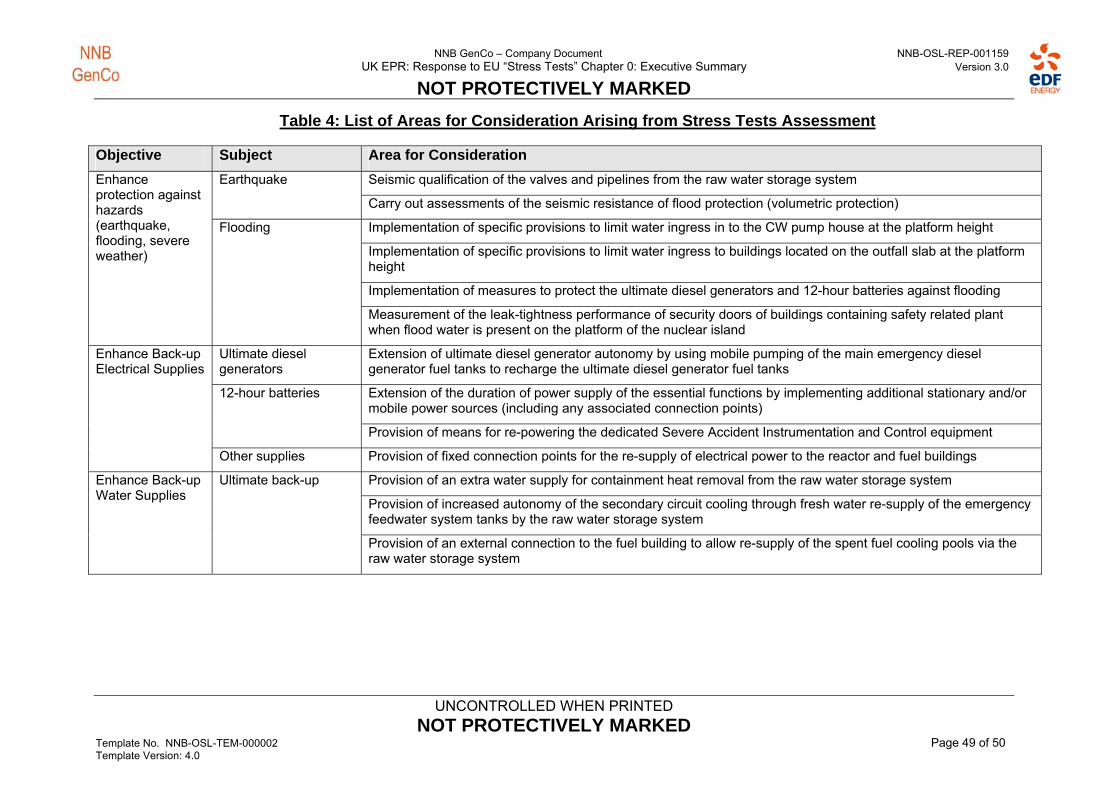
NNB GenCo – Company Document NNB-OSL-REP-001159 UK EPR: Response to EU “Stress Tests” Chapter 0: Executive Summary Version 3.0
NOT PROTECTIVELY MARKED
UNCONTROLLED WHEN PRINTED
NOT PROTECTIVELY MARKED Template No. NNB-OSL-TEM-000002 Page 49 of 50 Template Version: 4.0
Table 4: List of Areas for Consideration Arising from Stress Tests Assessment
Objective Subject Area for Consideration
Seismic qualification of the valves and pipelines from the raw water storage system Earthquake
Carry out assessments of the seismic resistance of flood protection (volumetric protection)
Implementation of specific provisions to limit water ingress in to the CW pump house at the platform height
Implementation of specific provisions to limit water ingress to buildings located on the outfall slab at the platform height
Implementation of measures to protect the ultimate diesel generators and 12-hour batteries against flooding
Enhance protection against hazards (earthquake, flooding, severe weather)
Flooding
Measurement of the leak-tightness performance of security doors of buildings containing safety related plant when flood water is present on the platform of the nuclear island
Ultimate diesel generators
Extension of ultimate diesel generator autonomy by using mobile pumping of the main emergency diesel generator fuel tanks to recharge the ultimate diesel generator fuel tanks
Extension of the duration of power supply of the essential functions by implementing additional stationary and/or mobile power sources (including any associated connection points)
12-hour batteries
Provision of means for re-powering the dedicated Severe Accident Instrumentation and Control equipment
Enhance Back-up Electrical Supplies
Other supplies Provision of fixed connection points for the re-supply of electrical power to the reactor and fuel buildings
Provision of an extra water supply for containment heat removal from the raw water storage system
Provision of increased autonomy of the secondary circuit cooling through fresh water re-supply of the emergency feedwater system tanks by the raw water storage system
Enhance Back-up Water Supplies
Ultimate back-up
Provision of an external connection to the fuel building to allow re-supply of the spent fuel cooling pools via the raw water storage system

NNB GenCo – Company Document NNB-OSL-REP-001159 UK EPR: Response to EU “Stress Tests” Chapter 0: Executive Summary Version 3.0
NOT PROTECTIVELY MARKED
UNCONTROLLED WHEN PRINTED
NOT PROTECTIVELY MARKED Template No. NNB-OSL-TEM-000002 Page 50 of 50 Template Version: 4.0
Objective Subject Area for Consideration
Establishment of passive or automatic opening of the spent fuel cooling pool hall to the nuclear auxiliary building to improve protection to over-pressurisation of the spent fuel pool hall
Carry out a study of the equipment and organizational arrangements needed to facilitate the safe positioning of a fuel assembly being handled during a loss of electrical power event.
Integration of selected fuel building instrumentation in to the severe accident I&C scheme
Addition of a remote operation capability to valves for introduction of extra water in the reactor building through the containment heat removal system spray nozzles
Setting up a suitable communication system on the site in order to manage situations involving total loss of electrical power (i.e. sound-powered telephones)
Carry out a study and investigate the provision of diverse means of providing emergency feed water to the steam generators
Carry out a study and investigate the provision of further systems or equipment to control containment over-pressure in severe accident conditions.
Carry out studies to investigate impact and advantages/disadvantages of adding means of cross connection between individual trains of safety systems. Both electrical and fluid systems to be considered
Equipment operability
Addition of diesel driven fire pumps
Check containment penetration leakage beyond the current qualification requirements for the reactor containment
Qualify the performance of instrumentation required for monitoring containment integrity for beyond design basis conditions
Equipment reliability
Qualify the performance of the available instrumentation in the spent fuel cooling pool for prolonged boiling conditions
Provision of a mobile pump for introduction of water in to the reactor building through the containment heat removal system spray nozzles
Mobile equipment
Provision of a high power mobile emergency generator
Carry out a study of the risk of hydrogen production due to radiolysis of water in the spent fuel cooling pool and if necessary identify and install additional equipment
Releases
Carry out a study into the prevention and mitigation of hydrogen gas accumulation in the fuel building
Enhance Severe Accident Management
Procedures Ensure that severe accident management procedures provide contingencies for events which exceed both design basis and design extension conditions.


![Y.[2-(2-Methyl-5-nitroimidazolyl)ethyl]-4-(2-nitroimidazolyl ...cancerres.aacrjournals.org/content/canres/55/3/574.full.pdf · NNB at 3.2 mM, providing an intraexperiment mean Ttil](https://static.fdocuments.us/doc/165x107/5e4609b24067f13422301cf2/y2-2-methyl-5-nitroimidazolylethyl-4-2-nitroimidazolyl-nnb-at-32-mm.jpg)