NL-27 INSTRUCTION MANUAL - Acoustic Research Labs Pty Ltd user manual.pdf · for measurement...
52
INSTRUCTION MANUAL Sound Level Meter NL-27 3-20-41 Higashimotomachi, Kokubunji, Tokyo 185-8533, Japan http://www.rion.co.jp/english/
Transcript of NL-27 INSTRUCTION MANUAL - Acoustic Research Labs Pty Ltd user manual.pdf · for measurement...

INSTRUCTION MANUAL
Sound Level Meter
NL-27
3-20-41 Higashimotomachi, Kokubunji, Tokyo 185-8533, Japan
http://www.rion.co.jp/english/

FOR SAFETY
In this manual, important safety instructions are specially marked as shown below. To prevent the risk of death or injury to persons and severe damage to the unit or peripheral equipment, make sure that all instructions are fully understood and observed.
Important
Note
Disregarding inst ruct ions printed here incurs the risk of damage to the product.
Mentioned about the tips to use this unit properly. (This messages do not have to do with safety.)

i
Precautions
• Operate the unit only as described in this manual.
• Do not touch any parts of the unit other than necessary for operation.
• Do not drop the unit. Protect it from shocks and vibration.
• The permissible environmental temperature range for operation of the unit is -10 to +50°C. Relative humidity must be between 10% and 90%.
• Do not use or store the unit in locations which may be subject to water, direct sunlight, high temperatures or humidity. Also protect the unit from air with high salt or sulphur content, gases or the infl uence of chemicals.
• Do not forget to turn the unit off after use. Remove the batteries if the unit is not to be used for some time.
• When disconnecting cables, always hold the plug and do not pull the cable.
• To clean the unit, use only a dry cloth or a cloth lightly moistened with water. Do not use chemical cleaning cloths, solvents or alcohol-based cleaners to prevent the possibility of deformation and discoloring.
• Do not insert any objects such as pins, metal scraps, conducting plastic etc. into any opening on the unit.
• Do not disassemble the unit or attempt internal altera-tions.
• In case of malfunction, do not attempt any repairs. Note the condition of the unit clearly and contact the supplier.
• When disposing of the unit or the batteries, follow national and local regulations regarding waste disposal.

ii
ContentsPrecautions ........................................................................................... iOutline ................................................................................................ 1Controls and Functions ....................................................................... 2Batteries .............................................................................................. 4Attachments ........................................................................................ 6
Windscreen .................................................................................... 6Windscreen fall out prevention rubber ........................................... 6Silicon cover ................................................................................... 7Hand strap ...................................................................................... 8Connecting external equipment ..................................................... 9
State transition diagram (functions and operation keys) ................... 10Measurement screen and processing screen ...................................... 12Power on and off ............................................................................... 14Measurement ..................................................................................... 14Calibration ........................................................................................ 15Menu settings .................................................................................... 16Sleep mode ........................................................................................ 18Recalling stored data ......................................................................... 19Initializing ......................................................................................... 20Specifi cations .................................................................................... 21Description for IEC 61672-1 ............................................................. 26
IEC61672-1 (JIS C 1509-1) Frequency Response ......................... 37Reference incidence direction and reference point position ......... 39Frequency Response .................................................................... 39Effect of Windscreen WS-14 ....................................................... 40The greatest susceptibility confi guration for radio frequency fi elds . 42Statement of conforming to the basic statement ......................... 43Adjustment data for sound calibrator ........................................... 43The lower and upper limits of the linear operating range ............ 43Directional Characteristics .......................................................... 44Random incidence response ......................................................... 46

1
Ou
tline
OutlineThis unit is a sound level meter that complies with the Japan measurement law, JIS, and IEC. The microphone is a 1/2-inch electret condenser (UC-52). It has a wide 107-dB linearity range, measuring sound levels between 30 and 130 dB, with no need to select the range. The unit has an LCD panel, operation keys, an AC monitor output connector, a DC out connector, and a USB connector. It is able to measure the following items.• Sound level Lp
• Equivalent continuous sound level Leq
• Maximum sound level Lmax
• Sound exposure level LE
• C weighted peak sound level LCpeak
You can send data you have stored with the manual store func-tion through a USB adapter cable (optional accessory) to a computer. It is powered by two size AAA batteries. The main unit and preamplifi er are a single unit so it is not possible to extend the microphone.This unit has the following two level ranges.Wide range: This measures the range between 30 and 137 dB
and allows simultaneous measurement of Lp, Leq, Lmax, and LE.
Peak range: Along with the processing results for wide range, this range also measures LCpeak, but the lower limit for measurement becomes 65 dB.
Resume functionThe following items maintain the same settings they had when you turn the unit off the next time you turn the unit on.• Measurement time• Time weighting characteristics• Level range• Address indication
The following items have predefi ned settings upon startup.• Frequency weighting characteristic A• Display processing value type Lp

2
Co
ntro
ls and
F
un
ction
s
Controls and FunctionsFront Panel
Microphone/preamplifi erMicrophone and preamplifi er are integrated in a single enclosure. An extension cable cannot be used.
START/STOP keyPress to start or stop processing. Also used to change setting values in the calibration screen, menu screen, and recall screen.
MODE keyChanges the processing result display in the measurement screen and processing screen. Also used to change setting values in the calibration screen, menu screen, and recall screen.
A/C/Cal keyThis key selects the frequency weighting characteristics, calibra-tion screen and recall screen. Pressing and holding this key in the measurement screen changes it to the menu screen.
POWER keyTurns the unit on and off.
SOUND LEVEL METER NL-27
START/STOP MODE A/C/CAL
POWER
MENU
MicrophonePreamplifier
START/STOP key
MODE key
A/C/CAL key
POWER key

3
Co
ntro
ls and
F
un
ction
s
Side View
External connectorThis connector is composed of a DC out connector, an AC moni-tor output connector, and a USB connector. (The connector can only be used for one purpose at a time.)
DC out connectorA DC signal corresponding to the sound level can be output from here. The signal after frequency weighting, time weighting, and logarithmic compression is output here (constant output when a DC output cable is connected). Connect the unit with the optional DC output cable to external equipment.
AC monitor output connectorAn AC signal weighted with frequency weighting characteristic Z is output here (constant output when an AC monitor output cable is connected). Connect the unit with the optional AC monitor output cable to external equipment.When 110 dB is displayed, output is 1 Vrms
+600 mVrms- 400 mVrms .
(The upper limit of the output voltage is 1.8 Vrms)
USB connectorConnect the unit with the optional USB adapter cable to com-puter and send stored data. (Download the necessary software from our homepage.)
Strap mountAttach the hand strap here (see page 8). Pass your wrist through this strap when holding the unit for measuring.
DC out connectorAC monitor output connectorUSB connector
Strap mount
External connector

4
Batteries
Tripod mounting threadMount the unit on a camera tripod with this thread.
Battery compartmentInsert two size AAA (IEC R03, LR03) batteries here.
BatteriesInserting the Batteries
Important
Make sure the unit is turn off before inserting the batteries.
1. Remove the battery compartment cover on the rear of the unit.
2. Insert two size AAA (IEC R03, LR03) batteries into the battery compartment. Insert correctly as indicated in the compartment.
3. Replace the battery compartment cover.
Rear View
Tripod mounting thread
Battery compartment
Batterycontact
Batterycontact
Press and pull in the arrow direction
Insert two size AAA(IEC R03, LR03) batteries
Remove the batterycompartment cover

5
Batteries
Important
Take care not to reverse the (+) and (-) polar-ity when inserting the batteries. If batteries are inserted with wrong polarity, the unit will not operate.
Always use two identical batteries, and replace batteries only as a set. Mixing battery types or old and new batteries can lead to damage.
Remove the batteries from the unit when it is not used.
Do not subject the battery connectors to strong force or stress. Damaged springs can lead to loss of proper battery contact.
Battery life (at 23°C, using wide range)Manganese batteries: approx. 3 hoursAlkaline batteries: approx. 9 hoursBattery life will be reduced by 20% when a DC output cable is connected.
Battery indicationIndicates battery charge. When the indicator starts to fl ash, cor-rect measurement is no longer possible. Replace the batteries with fresh ones.
Full charge Indicator flashing(replace the batteries)
Important
If the indicator starts fl ashing during process-ing, processing will end at that point.You cannot start processing with the START/STOP key when the battery indication is fl ash-ing.

6
Attach
men
ts
AttachmentsWindscreen
We recommend attaching the windscreen to reduce wind noise.
Windscreen fall out prevention rubber (hereafter called “fall out prevention rubber”)
Prevents the windscreen from dropping off the microphone.This is attached to the unit at the time of shipment.
Important
The windscreen can easily drop off the unit, so we recommend attaching the fall out pre-vention rubber.
Be sure to follow the instructions in the fol-lowing diagram when attaching or detaching the fall out prevention rubber. Turning it in the opposite direction may loosen the microphone and cause it to fall off.
SOUND LEVEL METER NL-27
Turn the fall outprevention rubberonly in this direc-tion.
Windscreen
Fall out preventionrubber

7
Attach
men
ts
Silicon coverThe silicon cover protects the unit from shocks and also makes it easier to grip when held.Fit it to the unit with the windscreen removed, as shown in the following diagram.
Note
You cannot use external connector when the silicon cover is fi tted.You can attach the hand strap to the silicon cover strap mount.
SOUN
DLE
VEL
METE
RNL
-27
STAR
T/ST
OPMO
DEA/
C/CA
L
POW
ER
MENU
SOUN
DLE
VEL
MET
ERNL
-27
STAR
T/ST
OPM
ODE
A/C/
CAL
POW
ER
MEN
U
SOUN
DLE
VEL
MET
ERNL
-27
STAR
T/ST
OPM
ODE
A/C/
CAL
POW
ER
MEN
U
Silicon coverstrap mount

8
Attach
men
ts
Hand strapTo help prevent dropping of the unit, pass your wrist through this strap when holding the unit for measuring.Attach the hand strap as shown below.
Note
Attach the hand strap to the silicon cover if you have fi tted the unit with the silicon cover.
Strap mountHand strap
When you have not fitted the silicon cover
POWER
When you have fitted the silicon cover
Silicon cover strap mount

9
Attach
men
ts
Connecting external equipmentYou can connect external equipment, such as a data recorder, level recorder, or computer, to the external connector.Connect as shown in the following diagram.
Note
The connector has the ability to act as a DC out connector, an AC monitor output connector, or a USB connector, but it can perform only one of these functions at a time.
SOUND LEVEL METER NL-27
START/STOP MODE A/C/CAL
POWER
MENU
External connector
NL-27
DC outputcableCC-98D
USB adapter cableCC-98S
Data recorder DA-20 or DA-40 etc.
Data recorder DA-20 or DA-40,analyzer SA-01 or SA-78 etc.
(Connect to the DC input connector)
(Connect to the AC input connector)
A computer etc.
(Connect to the USB connector)
AC monitoroutput cableCC-98A

10
State tran
sition
d
iagram
START/STOP key
START/STOP key, orafter the measurementtime has elapsed
Processingscreen
Measurementscreen
Calibrationscreen
Reduce volume withthe START/STOP key
Move the addressdown with theSTART/STOP key
Move the address upwith the MODE key
Raise volume withthe MODE key
A/C/Cal key
A/C/Cal key
A/C/Cal key
A/C/Cal key
Frequency weight-ing characteristic
A
Frequency weight-ing characteristic
C
External calibration
Internal calibration
Recall screen
Startup Power on
A/C/Cal key
State transition diagram (functions and operation
keys)

11
State tran
sition
d
iagram
Pressing the MODE key in the measurement screen or processingscreen changes the display in the following order.Lp Leq Lmax LE( LCpeak) LpLCpeak only appears when peak range is selected.
Press andhold theA/C/CALkey
Press andhold theA/C/CALkey
Menu screen
Range setting
A/C/Cal key
A/C/Cal key
A/C/Cal key
Setting timeweighting char-
acteristics
Setting meas-urement time
Change the setting with theSTART/STOP key or MODE key
Wide Peak
Change the setting with theSTART/STOP key or MODE key
F S
Change the setting with theSTART/STOP key or MODE key1 m 5 m 10 m 1 h 1 m

12
Measu
remen
t scre
en
Measurement screen and processing screen
Processingmark
Processing re-sult under rangeindication
Sound levelunder rangeindication
Frequency weightingcharacteristics
Processing re-sult symbol
Time weightingcharacteristics
Level indication
Bar graph, lev-el range scale
Processing re-sult overloadindication
Sound leveloverload indi-cation
Battery indica-tion
Address numberElapsed timeMeasurement time
Measurement timeThe measurement time set in the menu screen (see state transi-tion diagram, page 11).
Elapsed timeThe amount of time elapsed since processing started.
Address numberThe address where the processing result (the next process result in the measurement screen) is stored.
Battery indicationIndicates battery charge. (see page 5)
Bar graph, level range scaleShows the sound level in a bar graph.
Sound level overload indicationShows that the sound level has exceeded the measurement range.

13
Measu
remen
t scre
en
Processing result overload indicationAppears during processing when the sound level exceeds the measurement range, and remains until the next process starts (when a processing result is shown).
Level indicationShows the sound level (Lp) and each processing result (Leq, Lmax, LE, and LCpeak) as digits. Switch the display with the MODE key.LCpeak is processed and shown only when peak range (see page 16) is selected.
Time weighting characteristicsShows the time weighting characteristics selected in the menu screen.
Processing result symbolShows the relevant symbol for the displayed processing result (Leq, Lmax, LE, or LCpeak).
Frequency weighting characteristicsChange with the A/C/CAL key. See the state transition diagram (page 10).
Processing result under range indicationIf the sound level falls below the measurable limit (-0.6 dB) dur-ing processing, this appears until the next process starts (when a processing result is shown).
Sound level under range indicationAppears when the sound level falls below the measurable limit (-0.6 dB).
Processing markFlashes during processing.

14
Po
wer/
Measu
ring
Power on and offPress the POWER key for 0.5 seconds or more to turn the power on or off.
MeasurementSelecting frequency weighting characteristics
In the measurement screen, press the A/C/CAL key to select either frequency weighting characteristic A or C. (See the state transition diagram on page 10)
Processing (measurement)Press the START/STOP key to start the processing.The processing mark fl ashes during processing. Additionally, pressing the MODE key switches the display to show processing results (Lp, Leq, Lmax, LE, or LCpeak) made up to that point.Processing stops when the measurement time elapses or you press the START/STOP key.
Storing processing dataWhen processing stops, the Leq, Lmax, LE, or LCpeak process-ing results are automatically stored, and the address number increases by one.

15
Calib
ration
CalibrationInternal calibration (calibration with an electronic signal)
Calibration with the built-in oscillator (1 kHz, sinusoidal wave).In the measurement screen, press the A/C/CAL key to switch to the internal calibration screen.(See the state transition diagram on page 10)
Press the START/STOP key (Down) or MODE key (Up) to adjust the volume to 94.0 dB.
Sound calibration (calibration with a sound calibrator)
Use optional sound calibrator NC-74.In the internal calibration screen, press the A/C/CAL key to switch to the sound calibration screen.
Attach the microphone to NC-74 and turn NC-74 on. Wait at least 30 seconds, then press the START/STOP key (Down) or MODE key (Up) to adjust the volume to 93.9 dB.
Internal calibration screen“Int”, “Cal”, and “94.0dB” appear on the display.The frequency weighting characteristic is fixed to C and the time weighting characteristic is fi xed to F.
Sound calibration screen“Aco” and “Cal” appear on the display.The frequency weighting characteristic is fi xed to C and the time weighting char-acteristic is fi xed to F.

16
Men
u settin
gs
Menu settingsIn the measurement screen, press and hold the A/C/CAL key to switch to the menu screen (not available during processing).
Range settingPress the START/STOP key or the MODE key to select the following range settings.
Wide: Measurement range: 30 to 130 dB, LCpeak cannot be processed
Peak: Measurement range: 65 to 130 dB, LCpeak can be processedEven if the frequency weighting characteristic is A, LCpeak is processed as C.
When wide range isselected
Flashes every0.5 seconds
Press the A/C/CAL key to switch to the time weighting char-acteristic settings.Press and hold the A/C/CAL key to return to the measurement screen.
When peak range isselected
Flashes every0.5 seconds

17
Men
u settin
gs
Setting time weighting characteristicsPress the START/STOP key or the MODE key to select the following settings.
F (fast), S (slow)Press the A/C/CAL key to switch to the measurement time settings.Press and hold the A/C/CAL key to return to the measurement screen.
Flashes every0.5 seconds
Setting measurement timePress the START/STOP key or the MODE key to select the following settings.
1 m (1 minute), 5 m (5 minutes), 10 m (10 min-utes), 1 h (1 hour)
Press the A/C/CAL key to return to the measurement screen.
Flashes every0.5 seconds

18
Men
u settin
gs
Sleep modeWith the measurement screen being shown and no key is pressed for 10 minutes, the unit enters sleep mode and the sleep mode screen appears. Power consumption is 30% of normal in sleep mode.
Situations where the unit will not enter sleep modeThe unit will not enter sleep mode in the following situations, even if no key is pressed for 10 minutes.If the processing screen, calibration screen, recall screen, or menu screen is displayed.If a cable is connected to the external connector (any one of the three types).
Waking the unit from sleep modePress any key in sleep mode to return to the measurement screen.

19
Recall
Recalling stored dataIn the measurement screen (frequency weighting characteristic C), press the A/C/CAL key three times to show the recall screen (see the state transition diagram on page 10). The most recent processing result is shown.
Press the START/STOP key or the MODE key to change the displayed data as follows (LCpeak appears only when peak range is selected).
Measurement time Elapsed time Address
Shows that thisis the recallscreen.
Level rangescale(The bar graphis not shown)
Measurement result("--.-" appears if no data has beenstored)
Press and hold the START/STOP or the MODE key to move through the addresses faster.
--- Address n-1 Address n Address n+1 ---
To return to the measurement screenPress the A/C/CAL key
Address n-1 Leq Lmax LE (LCpeak)
Address n Leq Lmax LE (LCpeak)
Address n+1 Leq Lmax LE (LCpeak)

20
Initializin
g
ALL and CLrflash alternatelyon the screen ev-ery 0.5 seconds.
Clearing stored dataPress the A/C/CAL key for 3 or more seconds while the recall screen is shown and a screen asking you to confi rm clearing of the data appears.
Data clear confi rmation screen
Press the START/STOP key and all stored data is cleared, then the recall screen appears again.Press the A/C/CAL key to cancel the operation and return to the recall screen.
InitializingPower the unit on while pressing the START/STOP key and the settings in the unit are initialized.
Initial setting valuesMeasurement time 10 m (10 minutes)Time weighting characteristics F (Fast)Level range WideAddress 1

21
Sp
ecifi cation
s
Specifi cationsApplicable legislation The Japan measurement law - Sound
level meterJIS C 1509-1:2005 Class 2IEC 61672-1:2002 Class 2CE Marking (EMC Directive 2004/108/EC)WEEE DirectiveChinese RoHS (units shipped to China only)
Measurement functionsProcessing type Sound level Lp
Equivalent continuous sound level Leq
Sound exposure level LE
Maximum Sound level Lmax
C weighting peak sound level LCpeak (measurement possible only when peak range is selected)
Measurement times 1 minute, 5 minutes, 10 minutes, or 1 hour
Microphone 1/2-inch electret condenser microphoneModel: UC-52Sensitivity: -33 dB±3 dB (re.1 V/Pa)
Measurement level range Wide rangeA weighting: 30 dB to 130 dBC weighting: 36 dB to 130 dB
Peak rangeA weighting: 65 dB to 130 dBC weighting: 65 dB to 130 dB
Total range 30 dB to 137 dB (A weighting, 1 kHz)Peak sound level measurement range
65 dB to 140 dBInherent noise level Wide range
A weighting: 24 dB or lessC weighting: 30 dB or less
Peak rangeA weighting: 59 dB or lessC weighting: 59 dB or less

22
Sp
ecifi cation
s
Measurement frequency range 20 Hz to 8 kHzReference frequency 1 kHzReference sound pressure level 94 dBFrequency weighting characteristics
A and CTime weighting characteristics F (fast) and S (slow)Level range Wide range 30 to 130 dB
Peak range* 65 to 130 dB* Peak range is used when measuring
peak sound level.RMS detecting circuit Digital processingProcessing Digital
Sampling interval: 30.3 µs(Lp, Leq, Lmax, LE, LCpeak)
Calibration Calibration frequency: 1 kHzCalibration sound pressure level:
94 dBThe Japan measurement law:
Electronic calibration using an in-ternal electronic signal
JIS, IEC:sound calibration using NC-74
Windscreen Conforms to JIS C 1509-1 Class 2 and IEC 61672-1 Class 2 even when the windscreen is attached
Display TN positive display, refl ective typeNumeric readout 0.1 dB resolutionBar graph Scale range 100 dB, resolution 5 dB
(display update cycle 0.1 s)Warning indications Over (overload): appears at 137.4 dB (at
1 kHz)Under (underload): appears at measure-ment lower limit, -0.6 dB
Battery indication Battery charge is indicated in 3 stagesStoring processing results Processing results stored in the internal
memory when processing ends.Storing capacity: 199 pieces of data

23
Sp
ecifi cation
s
Stored data can be viewed in the recall screen. The stored data can also be sent to a computer through an optional USB adapter cable.
DC out connector DC output: 3 V (full scale), 25 mV/dBOutput impedance: 50 ΩLoad impedance: 10 kΩ or more
AC monitor output connector AC output:
1 Vrms +600 mVrms-400 mVrms
(at 110 dB)
(Upper limit: 1.8 Vrms)Overload: +2 dBOutput impedance: 600 ΩLoad impedance: 10 kΩ or moreFrequency weighting characteristics:
Z weightingUSB connector Use an optional USB adapter cable to
send stored data to a computer.Power requirements 2 size AAA (IEC R03, LR03) batteries
Power consumption:Approx. 80 mA (when operating at 3 V)(Approx. 30% in sleep mode)
Battery life (at normal temperature):Wide range
Approx. 9 hours (using alkaline batteries)Approx. 3 hours (using manga-nese batteries)
Peak rangeApprox. 7 hours (using alkaline batteries)Approx. 2 hours (using manga-nese batteries)
Battery life will be reduced by 20% when a DC output cable is connected.Power consumption increases by ap-proximately 20% during calibration.

24
Sp
ecifi cation
s
Environmental conditions for operation-10°C to 50°C, 10% to 90% R.H. (No condensation)
Dimensions Approx. 120 mm(H)×63 mm(W)×23.5 mm(D)
Weight Approx. 105 g (including batteries)Supplied accessories
Windscreen WS-14 1Hand strap VM-63-017 1Windscreen fall out prevention rubber
NL-27-014 1Silicon cover NL-27-026 1Size AAA alkaline batteries 2Instruction Manual 1Inspection certifi cate 1
Optional equipmentsSound calibrator NC-74AC monitor output cable CC-98ADC output cable CC-98DUSB adapter cable CC-98S

25
Sp
ecifi cation
s
SOUND LEVEL METER NL-27
START/STOP MODE A/C/CAL
POWER
MENU
23.5
120
63
Front View
Rear View
Right Side ViewLeft Side View
Dimensional Drawings Unit: mm

26
Descrip
tion
fo
r IEC Standard
paragraph Description Seealso Remark
5 Performance specifi cations5.1 General5.1.4 Confi guration & normal mode
of operation9.2.1 b) Confi guration
• NL-27• WS-14• Windscreen fall out
prevention rubber• Silicon cover (
Attachments)Normal mode of operation
Power on and offUnit powered
5.1.6 Models of microphone Appropriate procedures for use the sound level meter
9.2.1 c)9.2.5 b)
UC-52 Power on and off, Measurement , Calibration
5.1.7 Mounting of microphone 9.2.1 b) Attachments5.1.8 Identifi cation of computer soft-
wareN/A
5.1.10 Description of frequency weight-ings that are provided
9.2.2 c) A, C
5.1.12 Description of level ranges (@ A-weighted SPL @ 1 kHz )Instruction manual of the level range controls and function.Recommendation for selecting the optimum level range.
9.2.2 h)9.2.5 c)
30 dB to 137 dB
Menu settings
Menu settings
Description for IEC 61672-1

27
Descrip
tion
fo
r IEC
5.1.13 Reference SPLreference level range,Reference orientation, reference position of microphone.
9.2.5 a),9.3 a), b), c)
94.0 dBWide rangeFig. 1 Reference incidence direction and reference point position
5.1.14 Operating of the hold facility and the means for clearing a display that is held.
Measurement: Maximum time-weighted sound level L m a x, C weighted peak sound level
5.1.15 Dummy microphone: Design goal and tolerance
9.3 g) C a p a c i t a nc e of dummy microphone: 19 pF Tolerance: ±3 pF
5.1.16 Highest SPL and Peak-Peak input voltage without causing damage.
9.3 i) 150 dB28 Vp-p
5.1.17 Characteristics of each indepen-dent channel to be described
N/A
5.1.18 Initial time interval after switch-ing on power
9.2.5 e) Less than 1 min-utes.
5.2 Adjustment to indicated levels5.2.1 Model of sound calibrator(s) 9.2.4 a) NC-74 (RION)5.2.3 Procedure for calibration & ad-
justment with sound calibrator 9.2.4 c) C a l i b r a t i o n :
Acoustic cali-b r a t ion w i t h Sound Calibrator NC-74, 93.9 dB

28
Descrip
tion
fo
r IEC
5.2.45.2.5
Data for correction - with and without windscreen - for :- Deviation of average frequency response to uniform frequency response.- Case refl ection and microphone diffractionIncluding values for expanded uncertainties.In 1/3 octave frequencies for 63 Hz to 1 kHz and 1/12 octave fre-quencies for 1 kHz to 16 kHz
9.2.4 d)9.2.5 b)
Fig. 2 Frequency response of the microphone UC-52 (including the case refl ection)Fig. 4 Infl uence of WS-14 on acous-tic performance of NL-27
5.2.7 Adjustment data for sound cali-brator or electrostatic actuator (for A-weighted sound levels)
9.3 d) Tab. 2 Adjustment data for sound cali-brator
5.4 Frequency weightings5.4.12 Frequency response & toler-
ances of optional frequency responses
9.2.2 c) N/A
5.5 Level linearity5.5.9 A, C and Z weighted levels for
the lower and upper limit of the linear operating range.
9.3 e) Tab. 3 The lower and upper limits of the linear operating range
5.5.10 Starting point for the level lin-earity error
9.3 f) Tab. 3 The lower and upper limits of the linear operating range
5.5.11 How to test level linearity if dis-play range < linearity range
9.3 k) N/A
5.6 Self generated noise5.6.1 Self-noise at the more sensitive
ranges (including microphone)9.2.5 o)9.3 h)
Maximum valueA: <24 dBC: <30 dB

29
Descrip
tion
fo
r IEC
5.6.3 Self-noise at the more sensi-tive ranges with dummy micro-phone
9.3 h) Dummy microphone (19 pF)Maximum valueEqual to 5.6.1Typical valueA: 19 dBC: 24 dB
5.7 Time weighting F and S5.7.1 Description of time weightings
that are provided9.2.2 d) F, S
5.10 - 5.11 Overload and Under-range indication5.10.1 Operation & interpretation of
overload indicators9.2.5 k) M e a s u r e m e n t
screen and pro-cessing screen
5.11.1 Operation & interpretation of under-range indicators
M e a s u r e m e n t screen and pro-cessing screen
5.12 Peak C sound level5.12.1 Nominal range of LCpeak at for
each level range9.2.2 i) Specifi cations
5.14 Thresholds5.14 Operation of user-selectable
thresholds9.2.5 l) N/A
5.15 Display5.15.2 Description of the indication of
displayed quantities9.2.2 g) M e a s u r e m e n t
screen and pro-cessing screen
5.15.3 Description of the display 9.2.2 g) M e a s u r e m e n t screen and pro-cessing screen
5.15.4 Description of the displayed quantities
9.2.2 a) N/A
5.15.5 Statement of the display update rate
9.2.2 g) 1 second
5.15.6 Time interval for completion of the integration
9.2.5 f) N/A
5.15.7 Description of method for trans-ferring data to PC
9.2.5 m) Attachments

30
Descrip
tion
fo
r IEC
5.16 Analogue and digital outputs5.16.1 Electric output connector (AC
output)9.2.5 p) Frequency weight-
ing: Z
1 Vrms +600 mVrms-400 mVrms
(at 110 dB)Output range:1.8 Vrms or lessOutput impedance: 600 ΩLoad impedance: >10 kΩ
Electric output connector (DC output)
Frequency weight-ing: A, COutput voltage:3.0 V (at 130 dB),25 mV/dBOutput range:0.5 to 3.2 VOutput impedance: 50 ΩLoad impedance: >10 kΩ
5.17 Timing facilities5.17.1 Procedure to preset the integra-
tion time & time of the day 9.2.5 g) N/A
5.17.2 Statement of the minimum & maximum integration time
9.2.5 h) N/A
5.18 RF emissions and power supply disturbance5.18.1 Length & type of interface cable
and characteristics of connected devices
9.2.5 n) AC monitor output cable CC-98A (2 m)DC output cable CC-98D (2 m)USB adapter cable CC-98S (2.5 m)All cables shielded

31
Descrip
tion
fo
r IEC
5.18.2 Operating mode or highest radio frequency emissions
9.3 n) Operation mode: normal operationConnection pattern: USB adapter cable CC-98S (with ferrite cores)
5.20 Power supply5.20.2 Maximum and minimum power
supply voltage9.3 j Maximum: 3.6 V
Minimum: 1.8 V5.20.3 Battery types & battery life 9.2.3 a) Batteries5.20.4 Operation from an external
power supply 9.2.3 c) N/A
5.20.5 Public power supply voltage 9.2.3 d) N/A6 Environmental, electrostatic and radio frequency criteria6.1.2 Time interval for needed to
stabilize after environmental changes
9.3 l) Temperature change: < 1 hourHumidity change: < 1 hourS t a t i c p r e s s u r e change: < 5 minutes
6.2.2 (Note)
Measurement when static pres-sure is < 85 kPa
Calibration and mea-surement performed in this environment using Sound Cali-brator NC-74
6.5.2 Degradation of functions by electrostatic discharge
9.2.7 b) Measurement value affected temporar-ily by electrostatic discharge
6.6.1 Operating mode with least im-munity to AC power frequency fi elds and RF fi elds
9.3 o) Fig. 5Operation mode: normal operationConnection pattern: USB adapter cable CC-98S (with ferrite cores)
6.6.4(Note)
Field strength for conforming (in case > 10 V/m)
9.3 m) N/A
32
Descrip
tion
fo
r IEC
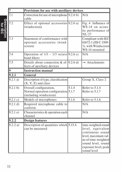
7 Provisions for use with auxiliary devices7.1 Correction for use of microphone
cable9.2.6 b) N/A
7.2 Effect of optional accessories (windscreen)
9.2.6 a) Fig. 4 Infl uence of WS-14 on acous-tic performance of NL-27
7.3 Statement of conformance with optional accessories (wind-screen)
Compliant with IEC 61672-1 (JIS C 1509-1), with Windscreen WS-14 mounted
7.4 Operation of 1/1 - 1/3 octave band fi lters
9.2.6 c) N/A
7.5 Details about connection & ef-fects of auxiliary devices
9.2.6 d) Attachments
9 Instruction manual9.2.1 General9.2.1 a) Description of type, classifi cation
(X, Y, Z) and class Group X, Class 2
9.2.1 b) Overall confi guration, Normal operation confi guration (including windscreen)
5.1.45.1.7
Refer to 5.1.4Refer to 5.1.7
9.2.1 c) Models of microphones 5.1.6 Refer to 5.1.69.2.1 d) Required microphone cable to
conformN/A
9.2.1 e) Characteristics & operation each channel
N/A
9.2.2 Design features9.2.2 a) Description of quantities which
can be measured5.15.4 time-weighted sound
level, equivalent continuous sound level, maximum val-ue of time-weighted sound level, sound exposure level, peak sound level

33
Descrip
tion
fo
r IEC
9.2.2 b) Relative free-fi eld response as function of incidence angle and frequency (detailed tabular de-scription)
Directional Charac-teristics with Hori-zonta l Direct ion (Fig. 6), Vertical Direction (Fig. 7)
9.2.2 c) Description of the frequency weightings
5.1.105.4.12
Refer to 5.1.10Refer to 5.4.12
9.2.2 d) Description of the time weight-ings
5.7.1 Refer to 5.7.1
9.2.2 e) Identifi cation of the level ranges (A-weighted @ 1 kHz)
5.1.12 Refer to 5.1.12
9.2.2 f) Operation of the level range control
5.1.12 Refer to 5.1.12
9.2.2 g) Description of the display and update rates
5.15.2-3-4-5
Refer to 5.15.2-3-4-5
9.2.2 h) Total range of A- weighted SPL (@ 1 kHz)
5.1.12 Refer to 5.1.12
9.2.2 i) Nominal range of LCpeak at for each level range
5.12.1 Refer to 5.12.1
9.2.2 j) Computer software to operate the SLM
5.1.8 Refer to 5.1.8
9.2.2 k) Design goals and tolerances for quantities which are not in the standard (T-weight 10 ms, LAIeq)
N/A
9.2.3 Power supply9.2.3 a) Battery types & battery life 5.20.3 Refer to 5.20.39.2.3 b) Description of the function of
battery check Batteries: Dis-play
9.2.3 c) Operation from an external power supply
5.20.4 Refer to 5.20.4
9.2.3 d) Public power supply voltage 5.20.5 Refer to 5.20.59.2.4 Adjustment to indicated levels9.2.4 a) Model of sound calibrator(s) 5.2.1 Refer to 5.2.19.2.4 b) Calibration check frequency 1 kHz9.2.4 c) Procedure for calibration & ad-
justment with sound calibrator 5.2.3 Refer to 5.2.3

34
Descrip
tion
fo
r IEC
9.2.4 d) Data for correction - with and without windscreen - for :- Deviation of average frequency response to uniform frequency response.- Case refl ection and microphone diffractionIncluding values for expanded uncertainties.In 1/3 octave frequencies for 63 Hz to 1 kHz and 1/12 octave fre-quencies for 1 kHz to 16 kHz
5.2.4 -5.2.5
Refer to 5.2.4 -5.2.5
9.2.5 Operating the sound level meter9.2.5 a) Reference direction 5.1.13 Refer to 5.1.139.2.5 b) Procedure to measure sound,
Infl uence of the instrument case and operator.
5.1.65.2.45.2.5
Refer to 5.1.6Refer to 5.2.4Refer to 5.2.5
9.2.5 c) Recommendation for selecting optimum level range
5.1.12 Refer to 5.1.12
9.2.5 e) Initial time interval after switch-ing on power
5.1.18 Refer to 5.1.18
9.2.5 f) Time interval for completion of the integration
5.15.6 Refer to 5.15.6
9.2.5 g) Procedure to preset the integra-tion time & time of the day
5.17.1 Refer to 5.17.1
9.2.5 h) Statement of the minimum & maximum integration time
5.17.2 Refer to 5.17.2
9.2.5 i) Operation of the “Hold” func-tion
Measurement: Measurement of maximum time-weighted sound level

35
Descrip
tion
fo
r IEC
9.2.5 j) Operation of the reset function or Leq, LE, Lpeak and overload
Measurement results (measurement val-ues, overload indi-cation, under-range indication) are reset when a new measure-ment is started. Time required for measurement initial-ization: < 1 second
9.2.5.k) Operation & interpretation of overload indicators
5.10.1 Refer to 5.10.1
9.2.5 l) Operation of user-selectable thresholds
5.14 Refer to 5.14
9.2.5 m) Description of method for trans-ferring data to PC
5.15.7 Refer to 5.15.7
9.2.5 n) Length & type of interface cable and characteristics of connected devices
5.18.1 Refer to 5.18.1
9.2.5 o) Self-noise at the more sensitive ranges (including microphone). Averaging time ≥ 30 s.
5.6.1 Refer to 5.6.1
9.2.5 p) Characteristics of AC and DC output
5.16.1 Refer to 5.16.1
9.2.6 Accessories9.2.6 a) Effect of windscreen (direc-
tional response and frequency weighting)
7.2 Refer to 7.2
9.2.6 b) Corrections for microphone cable 7.1 Refer to 7.19.2.6 c) Use of bandpass fi lters 7.4 Refer to 7.49.2.6 d) Connection of auxiliary devices 7.5 Refer to 7.59.2.7 Infl uence of environmental conditions9.2.7 a) Components intended for opera-
tion in controlled environmentNone
9.2.7 b) Degradation of functions by electrostatic discharge
6.5.2 Refer to 6.5.2
9.2.7 c) Statement for conformance to AC power frequency fi elds and RF fi elds
Statement of con-forming to the basic statement (Tab. 1)

36
Descrip
tion
fo
r IEC
9.3 Information for testing9.3 a) Reference sound pressure level 5.1.13 Refer to 5.1.139.3 b) Reference level range 5.1.13 Refer to 5.1.139.3 c) Microphone reference point 5.1.13 Refer to 5.1.139.3 d) For A-weighted sound levels:
Adjustment data for multi-fre-quency sound calibrator and/or electrostatic actuator
5.2.7 Refer to 5.2.7
9.3 e) Nominal A-weighted sound lev-els at the upper and lower limits of the linear operating range on each level range.- For frequencies 31.5 Hz, 1, 4, 8 and 12.5 kHz
5.5.9 Refer to 5.5.9
9.3 f) Starting point for the level lin-earity error- For frequencies 31.5 Hz, 1, 4, 8 and 12.5 kHz- At the reference level range
5.5.10 Refer to 5.5.10
9.3 g) Dummy microphone: Design goal and tolerance
5.1.15 Refer to 5.1.15
9.3 h) Self-noise at the more sensitive ranges with microphone and with dummy microphone
5.6.1 /5.6.3
Refer to 5.6.1 /5.6.3
9.3 i) Highest SPL and Peak-Peak input voltage to accommodate
5.1.16 Refer to 5.1.16
9.3 j) Maximum and minimum power supply voltage
5.20.2 Refer to 5.20.2
9.3 k) How to test level linearity if dis-play range < linearity range
5.5.11 Refer to 5.5.11
9.3 l) Time interval for needed to stabilize after environmental changes
6.1.2 Refer to 6.1.2
9.3 m) Field strength for conforming (in case > 10 V/m)
6.6.4 Refer to 6.6.4
9.3 n) Operating mode or highest radio frequency emissions
5.18.2 Refer to 5.18.2
9.3 o) Operating mode with least im-munity to AC power frequency fi elds and RF fi elds
6.6.1 Refer to 6.6.1

37
Descrip
tion
fo
r IEC
IEC61672-1 (JIS C 1509-1) Frequency Response"Nominalfrequency(Hz)"
"Exactfrequency(Hz)"
"UC-52FrequencyResponse(dB)"
"NL-27FrequencyResponse(dB)case refl ec-tion"
"NL-27ElectricalResponse(dB)"
"TotalResponse(dB)"
"Windscreeneffect(dB)"
"TotalResponse(WS-14combined)(dB)"
"Totalexpandeduncertainty"
63 63.10 0.0 0.0 -0.1 -0.1 0.0 -0.1 -0.1 80 79.43 0.0 0.0 -0.1 -0.1 0.0 -0.1 -0.1
100 100.0 0.0 0.0 -0.1 -0.1 0.0 -0.1 -0.1 125 125.9 0.0 0.0 0.0 0.0 0.0 0.0 0.0 160 158.5 0.0 0.0 0.1 0.1 0.0 0.1 0.1 200 199.5 0.0 0.0 0.1 0.1 0.0 0.1 0.1 250 251.2 0.0 0.0 0.1 0.1 0.0 0.1 0.1 315 316.2 0.0 0.0 0.1 0.1 0.0 0.1 0.1 400 398.1 0.0 0.0 0.1 0.1 0.0 0.1 0.1 500 501.2 0.0 0.0 0.0 0.0 0.0 0.0 0.0 630 631.0 0.0 0.0 0.1 0.1 0.0 0.1 0.1 800 794.3 0.0 0.0 0.0 0.0 0.0 0.0 0.0
1000 1000.0 0.0 0.2 0.0 0.2 -0.1 0.1 0.1 1060 1059.3 0.0 0.3 0.0 0.3 0.0 0.3 0.3 1120 1122.0 0.0 0.3 0.0 0.3 -0.1 0.2 0.2 1180 1188.5 0.0 0.3 0.0 0.3 0.0 0.3 0.3 1250 1258.9 0.0 0.3 0.0 0.3 -0.1 0.2 0.2 1320 1333.5 0.0 0.3 0.0 0.3 0.0 0.3 0.3 1400 1412.5 0.0 0.3 0.0 0.3 0.1 0.4 0.4 1500 1496.2 0.1 0.3 0.0 0.4 0.0 0.4 0.4 1600 1584.9 0.1 0.3 0.0 0.4 0.0 0.4 0.4 1700 1678.8 0.1 0.2 0.0 0.3 -0.1 0.2 0.2 1800 1778.3 0.1 -0.1 0.0 0.0 0.1 0.1 0.1 1900 1883.6 0.1 -0.1 0.0 0.0 0.1 0.1 0.1 2000 1995.3 0.2 -0.1 0.0 0.1 0.1 0.2 0.2 2120 2113.5 0.2 -0.1 0.0 0.1 0.2 0.3 0.3 2240 2238.7 0.2 0.0 0.0 0.2 0.2 0.4 0.4 2360 2371.4 0.2 0.0 0.0 0.2 0.1 0.3 0.3 2500 2511.9 0.3 -0.1 -0.1 0.1 0.2 0.3 0.3 2650 2660.7 0.3 -0.3 -0.1 -0.1 0.2 0.1 0.1 2800 2818.4 0.3 -0.6 -0.1 -0.4 0.2 -0.2 -0.2 3000 2985.4 0.4 -0.8 -0.1 -0.5 0.2 -0.3 -0.3 3150 3162.3 0.4 -0.8 -0.1 -0.5 0.2 -0.3 -0.3 3350 3349.7 0.4 -0.6 -0.1 -0.3 0.3 0.0 0.0 3550 3548.1 0.4 -0.4 -0.1 -0.1 0.4 0.3 0.3

38
Descrip
tion
fo
r IEC
"Nominalfrequency(Hz)"
"Exactfrequency(Hz)"
"UC-52FrequencyResponse(dB)"
"NL-27FrequencyResponse(dB)case refl ec-tion"
"NL-27ElectricalResponse(dB)"
"TotalResponse(dB)"
"Windscreeneffect(dB)"
"TotalResponse(WS-14combined)(dB)"
"Totalexpandeduncertainty"
3750 3758.4 0.4 -0.4 -0.1 -0.1 0.3 0.2 0.2 4000 3981.1 0.4 -0.5 -0.1 -0.2 0.4 0.2 0.2 4250 4217.0 0.4 -0.6 -0.1 -0.3 0.4 0.1 0.1 4500 4466.8 0.4 -0.3 0.0 0.1 0.5 0.6 0.6 4750 4731.5 0.3 0.1 0.0 0.4 0.4 0.8 0.8 5000 5011.9 0.3 0.5 0.0 0.8 0.4 1.2 1.2 5300 5308.8 0.2 0.2 0.0 0.4 0.4 0.8 0.8 5600 5623.4 0.2 0.0 0.0 0.2 0.5 0.7 0.7 6000 5956.6 0.1 -0.1 0.0 0.0 0.5 0.5 0.5 6300 6309.6 0.0 0.0 0.0 0.0 0.5 0.5 0.5 6700 6683.4 -0.1 0.2 0.0 0.1 0.3 0.4 0.4 7100 7079.5 -0.2 0.3 0.0 0.1 0.3 0.4 0.4 7500 7498.9 -0.4 0.5 0.1 0.2 0.3 0.5 0.5 8000 7943.3 -0.5 0.1 0.1 -0.3 0.2 -0.1 -0.1

39
Descrip
tion
fo
r IEC
Reference incidence direction and reference point position
Fig. 1 Reference incidence direction and reference point position
Frequency Response The frequency response of a sound fi eld microphone is ex-pressed as the frequency response in the reference direction of incidence (0º).The diagram below shows an example for the frequency response of the microphone UC-52.
Fig. 2 Frequency response of the microphone UC-52
Reference directionof incidence
Reference point positionCenter of diaphragm plane
-3.0
-2.5
-2.0
-1.5
-1.0
-0.5
0.0
0.5
1.0
1.5
2.0
2.5
3.0
Res
pons
e(d
B)
10 100 1 000 10 000 100 000Frequency (Hz)

40
Descrip
tion
fo
r IEC
Effect of Windscreen WS-14 The windscreen WS-14 reduces measurement errors due to wind noise. The WS-14 characteristics are shown below.
Fig. 3 Wind noise reduction effect
Frequency weighting A
40
50
60
70
80
90
100
110
120
130
1 10 100Wind velocity (m/s)
Win
dno
ise
leve
l(dB
)
NL-27
With WS-14
Frequency weighting C
40
50
60
70
80
90
100
110
120
130
1 10 100Wind velocity (m/s)
Win
dno
ise
leve
l(dB
)
NL-27
With WS-14

41
Descrip
tion
fo
r IEC
Fig. 4 Infl uence of WS-14 on acoustic performance of NL-27 (Referenced to NL-27 characteristics)
-3.0
-2.5
-2.0
-1.5
-1.0
-0.5
0.0
0.5
1.0
1.5
2.0
2.5
3.0
Res
pons
e(d
B)
10 100 1 000 10 000 100 000Frequency (Hz)

42
Descrip
tion
fo
r IEC
The greatest susceptibility confi guration for radio frequency fi elds
Fig. 5 The greatest susceptibility confi guration for radio frequency fi elds
SOUND LEVEL METER NL-27
START/STOP MODE A/C/CAL
POWER
MENU
Ferrite cores
Computer
Polarization direction isparallel to drawing plane
Antenna
Operation mode: normal operation
Connection pattern- USB adapter cable (with ferrite cores) CC-98S 2.5 m
NL-27
CC-98S

43
Descrip
tion
fo
r IEC
Statement of conforming to the basic statement Tab. 1 Statement of conforming to the basic statement
Immunity to AC power frequency fi elds
The specifi cation of IEC 61672-1 Class 2 is satisfi ed
Immunity to RF fi elds The specifi cation of IEC 61672-1 Class 2 is satisfi ed
Emissions The specifi cation of IEC 61672-1 Class 2 is satisfi ed
Adjustment data for sound calibratorTab. 2 Adjustment data for sound calibrator
Frequency (Hz) Correction (dB)
31.5 0.0 63 0.0
125 0.0 250 0.0 500 0.0
1000 0.1 2000 0.3 4000 1.3 8000 3.2
12500 6.5 16000 6.7
The lower and upper limits of the linear operating rangeTab. 3 The lower and upper limits of the linear operating range
A-weighting Sound level (dB)Frequency (Hz) 31.5 1 k 4 k 8 k
Upper 97.0 137.0 136.0 133.0Start 54.0 94.0 94.0 94.0
Lower 30.0 30.0 30.0 30.0
C-weighting Sound level (dB)Frequency (Hz) 31.5 1 k 4 k 8 k
Upper 134.0 137.0 136.0 133.0Start 94.0 94.0 94.0 94.0
Lower 36.0 36.0 36.0 36.0

44
Descrip
tion
fo
r IEC
Directional CharacteristicsThe directional characteristics of NL-27 is a measure of its dif-fering sensitivity for sound waves arriving from various angles. Since the electret condenser microphone used in the NL-27 is a pressure-sensitive type, it should be equally sensitive in all directions. However, refraction and cavity effects cause a certain microphone directional response at high frequencies.
Fig. 6 Directional Characteristics with Horizontal Direction
Fig. 7 Directional Characteristics with Vertical Direction
-15dB
-10dB
-5dB
0dB
5dB 10° 20°30°
40°50°
60°
70°
80°
90°
100°
110°
120°
130°140°
150°160°170°180°190°200°
210°220°
230°
240°
250°
260°
270°
280°
290°
300°
310°320°
330°340°
350° 0°
500 Hz
1 kHz
2 kHz
4 kHz
8 kHz
16 kHz
-15dB
-10dB
-5dB
0dB
5dB 10° 20°30°
40°50°
60°
70°
80°
90°
100°
110°
120°
130°140°
150°160°170°180°190°200°
210°220°
230°
240°
250°
260°
270°
280°
290°
300°
310°320°
330°340°
350° 0°
500 Hz
1 kHz
2 kHz
4 kHz
8 kHz
16 kHz

45
Descrip
tion
fo
r IEC
Tab. 4Directional Characteristics with Horizontal Direction
Tab. 5Directional Characteristics with Vertical Di-rection
An-gle
Frequency [Hz] An-gle
Frequency [Hz]501 1000 1995 3981 7499 15849 501 1000 1995 3981 7499 15849
0º 0 0 0 0 0 0 0º 0 0 0 0 0 010º -0.07 -0.01 -0.08 -0.03 -0.05 -0.23 10º -0.02 0.00 -0.05 0.06 0.10 -0.40 20º -0.07 -0.06 -0.07 -0.06 -0.15 -0.78 20º -0.01 -0.03 -0.04 0.01 0.06 -0.74 30º -0.02 -0.07 -0.04 -0.13 -0.19 -0.87 30º -0.02 -0.09 -0.08 -0.06 -0.21 -1.03 40º -0.04 -0.17 -0.04 -0.32 -0.46 -1.15 40º -0.04 -0.11 -0.05 -0.27 -0.66 -1.46 50º -0.10 -0.28 -0.08 -0.57 -0.81 -1.98 50º -0.08 -0.12 -0.07 -0.59 -0.86 -2.44 60º -0.09 -0.33 -0.01 -0.66 -1.38 -3.46 60º -0.13 -0.22 0.00 -0.89 -1.63 -3.57 70º -0.18 -0.46 -0.05 -0.46 -2.14 -4.94 70º -0.12 -0.31 0.12 -0.76 -2.52 -4.25 80º -0.19 -0.58 0.06 -0.26 -2.98 -5.75 80º -0.18 -0.47 0.06 -0.16 -3.09 -6.70 90º -0.22 -0.81 -0.01 -0.12 -3.94 -6.52 90º -0.14 -0.57 0.27 -0.57 -3.85 -7.44
100º -0.17 -0.80 -0.10 -0.32 -3.65 -6.83 100º -0.25 -0.73 -0.33 -0.65 -3.75 -7.25 110º -0.19 -0.87 -0.38 -0.61 -2.87 -9.21 110º -0.21 -0.83 -0.57 0.11 -4.02 -8.42 120º -0.21 -0.86 -0.82 -0.55 -3.07 -9.07 120º -0.18 -0.86 -0.86 0.20 -3.07 -8.93 130º -0.19 -0.84 -1.04 -0.51 -3.22 -7.88 130º -0.18 -0.85 -1.28 -0.35 -3.81 -9.82 140º -0.18 -0.75 -1.20 -1.09 -3.84 -8.54 140º -0.16 -0.81 -1.28 -1.36 -2.55 -8.96 150º -0.16 -0.70 -1.03 -1.49 -3.89 -9.86 150º -0.13 -0.78 -1.06 -1.98 -3.38 -10.66 160º -0.18 -0.64 -0.85 -1.37 -4.61 -10.87 160º -0.13 -0.70 -0.79 -1.42 -6.17 -7.11 170º -0.16 -0.57 -0.59 -0.75 -4.15 -9.62 170º -0.14 -0.62 -0.52 -0.40 -3.96 -12.72 180º -0.14 -0.56 -0.43 -0.24 -2.77 -8.17 180º -0.11 -0.57 -0.34 -0.28 -3.15 -8.29 190º -0.17 -0.57 -0.53 -0.70 -4.09 -9.28 190º -0.12 -0.54 -0.55 -0.32 -4.02 -10.20 200º -0.19 -0.57 -0.61 -0.71 -4.21 -9.72 200º -0.12 -0.59 -0.73 -0.95 -6.61 -9.93 210º -0.14 -0.66 -0.73 -1.56 -4.68 -9.87 210º -0.16 -0.70 -1.11 -1.98 -3.50 -10.46 220º -0.19 -0.77 -1.04 -1.42 -4.22 -9.25 220º -0.18 -0.76 -1.31 -1.60 -2.62 -8.78 230º -0.17 -0.80 -0.97 -0.90 -4.28 -8.43 230º -0.20 -0.80 -1.33 -0.53 -4.17 -10.20 240º -0.19 -0.87 -0.93 -0.56 -3.63 -7.85 240º -0.18 -0.78 -0.95 0.13 -3.46 -10.12 250º -0.18 -0.85 -0.64 -0.59 -3.14 -9.51 250º -0.22 -0.81 -0.53 -0.07 -4.02 -8.36 260º -0.16 -0.88 -0.25 -0.76 -3.27 -8.79 260º -0.22 -0.77 -0.11 -0.45 -4.01 -7.42 270º -0.19 -0.71 0.01 -0.26 -3.82 -6.08 270º -0.22 -0.62 0.06 -0.77 -3.93 -7.81 280º -0.14 -0.63 0.14 -0.09 -3.67 -6.17 280º -0.16 -0.47 0.18 -0.52 -3.29 -6.59 290º -0.11 -0.51 0.16 -0.40 -3.02 -5.49 290º -0.10 -0.35 0.22 -0.65 -2.72 -5.15 300º -0.11 -0.34 0.04 -0.67 -1.75 -4.15 300º -0.16 -0.21 -0.08 -1.06 -1.87 -3.95 310º -0.08 -0.20 -0.10 -0.58 -0.88 -2.09 310º -0.14 -0.14 -0.17 -0.82 -0.95 -2.87 320º -0.08 -0.11 -0.15 -0.37 -0.60 -1.57 320º -0.03 -0.15 -0.05 -0.35 -0.84 -1.96 330º -0.06 -0.08 -0.17 -0.24 -0.33 -1.29 330º -0.04 -0.09 -0.12 -0.09 -0.45 -1.15 340º -0.03 -0.03 -0.08 -0.06 0.00 -0.54 340º -0.01 -0.04 -0.07 0.03 -0.01 -0.49 350º -0.03 0.00 -0.10 -0.07 -0.03 -0.20 350º -0.02 0.00 -0.10 0.06 0.10 -0.22

46
Descrip
tion
fo
r IEC
Random incidence response
Fig. 8 Random incidence response
-10
-8
-6
-4
-2
0
2
Res
pons
e(d
B)
10 100 1 000 10 000 100 000
Frequency (Hz)


No. 53732 09-07