NITP 6.6 National Instrument Test Procedures for Automatic ... · 1. SCOPE . NITP 6.6 describes the...
28
NITP 6.6 National Instrument Test Procedures for Automatic Rail Weighbridges
Transcript of NITP 6.6 National Instrument Test Procedures for Automatic ... · 1. SCOPE . NITP 6.6 describes the...
NITP 6.6 National Instrument Test Procedures for Automatic Rail Weighbridges

© Commonwealth of Australia 2011
NMI V 6 First edition — June 2006 First edition, first revision — July 2007 NITP 6.6 First edition — December 2011
National Measurement Institute Bradfield Road, Lindfield, NSW 2070 PO Box 264, Lindfield, NSW 2070
T (61 2) 8467 3600 F (61 2) 8467 3610 W www.measurement.gov.au
PREFACE
On 30 June 2010 the uniform test procedures (i.e. relevant NMI V documents) were deemed to be national instrument test procedures (NITPs) for the purposes of section 18GG of the National Measurement Act 1960 (Cth).
In 2011 the NITPs were renumbered to better align the numbers with the classes of pattern approval and servicing licensee. As a result this document (NMI V 6) became NITP 6.6.
The only changes that have been made to the latest edition of this document are it has been rebranded, renumbered, renamed and its cross-references have been updated. In all other respects it is identical with NMI V 6.
NMI’s Chief Metrologist has determined that NITP 6.6 contains the test procedures for the verification of automatic rail weighbridges.
ABBREVIATIONS
d scale interval (used to verify/certify a weighbridge) e verification scale interval (used to test a control instrument) E error (E = P – L) I indication L load Lsub actual calculated value of the substitution load L additional load to next changeover point Max maximum capacity Min minimum capacity MPE maximum permissible error n total number of wagons in test train nmax maximum number of wagons per train nmin minimum number of wagons per train P indication prior to rounding (P = I + 0.5d – L) vmax maximum operating speed vmin minimum operating speed < less than less than or equal to
CONTENTS
Abbreviations ............................................................................................................................. ii
Explanation of Terms ................................................................................................................ iv
1. Scope ................................................................................................................................... 1
2. Equipment ........................................................................................................................... 1
3. Visual Inspection................................................................................................................. 1 3.1 Required Data........................................................................................................... 1 3.2 Characteristics of the Instrument.............................................................................. 2
4. Test Procedures ................................................................................................................... 2 4.1 Control Instrument ................................................................................................... 3 4.2 Reference Wagons.................................................................................................... 4 4.3 Test Train ................................................................................................................. 5 4.4 Weighing Performance............................................................................................. 5 4.5 Over-speed Test........................................................................................................ 7 4.6 Under-speed Test...................................................................................................... 7 4.7 Roll-back Safeguard Test ......................................................................................... 7 4.8 Over-weight Wagon Test ......................................................................................... 7
5. Suggested Sequence for Testing ......................................................................................... 7
Appendix A. Test Reports.......................................................................................................... 8
Appendix B. Checklist for Preparation and Planning .............................................................. 18
Appendix C. Worked Examples............................................................................................... 19
iii
iv
EXPLANATION OF TERMS
For explanations of other terms see General Information for Test Procedures.
Adjustment
Alteration of the measurement parameters to bring the instrument within the allowable MPEs for an instrument in use.
Calibration
The set of operations that (under specified conditions) establishes the relationship between the indicated or nominal value of an instrument and the corresponding known value of the measured quantity.
Certification
The examination of an instrument by a certifier (the holder, or an employee of the holder, of a servicing licence) in order to mark the instrument indicating that it conforms with the relevant test procedures.
Initial certification is the certification of a new instrument by a certifier, which does not bear a verification or certification mark and has never been verified or certified before.
Subsequent certification is any certification of an instrument by a certifier because the mark is no longer valid due to such reasons as: repairs or adjustments have been made that affect metrological performance; or the mark has been defaced or removed.
In-service Inspection
The examination of an instrument by an inspector or certifier to check that: the verification or certification mark is valid; and the errors do not exceed the MPEs permitted for in-service inspection.
In-service inspection does not permit the instrument to be marked with a verification or certification mark.
Verification
The examination of an instrument by an inspector in order to mark the instrument indicating that it conforms with the relevant test procedures.
Initial verification is the verification of a new instrument by an inspector, which does not bear a verification or certification mark and has never been verified or certified before.
Subsequent verification is any verification of an instrument by an inspector because the mark is no longer valid due to such reasons as: repairs or adjustments have been made that affect metrological performance; or the mark has been defaced or removed.
Re-verification is the examination of an instrument by an inspector to check that: the verification or certification mark is valid; and the instrument has not been modified in any way since verification or certification;
in order to mark the instrument indicating that it conforms with the relevant test procedures.
1. SCOPE
NITP 6.6 describes the test procedures for the verification, certification and in-service inspection of automatic rail weighbridges to ensure that they measure to within the maximum permissible errors specified in the National Measurement Regulations and that they comply with the certificate/s of approval.
These test procedures supersede the dynamic test in Test Procedure 20. Weighing-in-motion Weighing Instruments found in Inspectors Handbook Number 3.
Certificates of approval are based on NMI R 106. Automatic Rail Weighbridges. Refer to NMI R 106 for all metrological and technical requirements.
All weighbridges must also comply with the relevant Trade Measurement Act and Regulations.
Refer to NITP 6.1 to 6.4 National Instrument Test Procedures for Non-automatic Weighing Instruments when testing the control instrument.
2. EQUIPMENT
1. Certificate/s of approval.
2. Control instrument (see clause 4.1).
3. Reference wagons (see clause 4.2).
4. Test train (see clause 4.3).
5. Test reports (see Appendix A).
3. VISUAL INSPECTION
Visually inspect the weighbridge and record the following details on Test Report 1.
3.1 Required Data
1. Test report reference number.
2. Date of the test.
3. Type of test: verification, certification or in-service inspection (for in-service inspection ensure that the verification/ certification mark is in place).
4. Name of owner/user.
5. Address of owner/user.
6. Name of contact on site.
7. Address where weighbridge is located.
8. Manufacturer’s name or mark.
9. Importer’s name or mark (if applicable).
10. Model.
11. Serial number.
12. Certificate of approval number.
13. Accuracy class for train weighing.
14. Accuracy class for wagon weighing.
15. Maximum capacity.
16. Minimum capacity.
17. Scale interval.
18. Maximum wagon weight.
19. Minimum wagon weight.
20. Maximum operating speed.
21. Minimum operating speed.
22. Maximum number of wagons per train.
23. Minimum number of wagons per train.
24. Electric power supply voltage.
25. Electric power supply frequency.
26. Not to be used for liquid products (if applicable).
27. Direction of weighing (if applicable).
28. Scale interval of stationary load (if applicable).
29. Supplementary and other markings (if applicable).
12/2011 NITP 6.6, v1 1 of 24
3.2 Characteristics of the Instrument
1. Does the weighbridge comply with its certificate/s of approval?
2. Is the weighbridge being used in an appropriate manner?
3. Are all mandatory descriptive markings clearly and permanently marked on the data plate?
4. Is the data plate fixed on the weighing system?
5. Is the weighbridge in a suitable operational condition?
6. Are there any apparent obstructions to the operation of the weighbridge?
7. Is the indicating device accessible during normal operation?
8. Is the headwork protected against any other influence likely to affect its performance?
9. For rail lines in continuous systems:
Are the approaches and departures: securely fixed to the railway sleepers; surveyed to confirm the vertical deflection is not excessive; and tamped if survey shows vertical deflection to be excessive?
Note: Survey points should be on the weighbridge approach, over the weighbridge and also on the weighbridge departures.
Are the rail sleeper spacings positioned to specifications in relation to the transducers?
Is there at least 20 mm clearance between the transducer rail and ballast?
10. For rail lines in non-continuous systems:
Are the approaches and departures in the same plane as the weighbridge?
Are the rail lines fixed securely to the railway sleepers?
Are the rail lines positioned such that there is no excessive space between the live and dead rails?
11. For additional indicating devices: do they exactly repeat the information on the primary indication and does any device for price computation and/or ticket/label printing comply with the requirements of General Supplementary Certificate S1/0/A (or General Supplementary Certificates S1/0 for devices initially verified or certified prior to March 1992)?
4. TEST PROCEDURES
See Appendix B for a checklist to assist with preparation and planning.
Before testing begins you must:
discuss the test procedures with the administering authority;
ensure that adequate skilled personnel are available;
establish appropriate communication procedures between personnel;
ensure that all equipment is available and operational; and
ensure that enough time has been allowed for the testing.
During testing you should:
avoid any unnecessary commitment of resources; and
restrict unauthorised access.
The following series of test procedures determine if the performance of a weighbridge meets requirements and whether the weighbridge requires adjustment or service. When adjustment or service is required the testing procedure must be recommenced.
12/2011 NITP 6.6, v1 2 of 24
The sequence for testing (also see clause 5) is:
determine if the control instrument is suitable for determining the mass of the reference wagons, and then test the control instrument for compliance with NITP 6.1 to 6.4 (see clause 4.1);
reference wagons are prepared and the control instrument is used to determine the mass of the reference wagons (see clause 4.2);
the test train is assembled (see clause 4.3);
the weighing performance of the weighbridge is tested in all modes and the results are compared with the mass of the reference wagons when weighed on the control instrument (see clause 4.4); and
the weighbridge is tested for over-speed, under-speed, roll-back safeguard and over-weight wagon (see clauses 4.5 to 4.8).
4.1 Control Instrument
A control instrument is used to determine the mass of the reference wagons which will be used to test the weighbridge.
The control instrument shall:
be a non-automatic weighing instrument;
be pattern approved, or have an approved load cell and indicator that comply with General Certificate 6B/0, or have a letter of approval from NMI;
be capable of having standard masses deposited directly or indirectly on the load receptor easily and in total safety; and
be capable of weighing the reference wagons uncoupled.
An instrument constructed only for partial weighing may be used as the control instrument as long as end-and-end weighing (see clause 4.2.2) is successfully applied.
Note: The weighbridge under test may be used as a control instrument as long as it complies with all the requirements for a control instrument.
First, use one of the two methods in Test Report 2 to determine if the control instrument is suitable, and meets the accuracy requirements required for it to determine the mass of the maximum and minimum reference wagons (see Appendix C.1 for a worked example). The control instrument shall be at least three or five times more accurate than the weighbridge, namely:
When the weighbridge under test is used as the control instrument and the weighing of the reference wagons is commenced within 24 hours of testing the control instrument, the control instrument shall be at least three times more accurate than the weighbridge.
In all other circumstances the control instrument shall be at least at least five times more accurate than the weighbridge. However if the reference wagons are not weighed within 28 days of testing the control instrument you must consult the administering authority. It may be acceptable to use the control instrument if the tests for repeatability and eccentricity are repeated. These are the minimum tests required to provide confidence that the control instrument is still within the required MPE.
Then test the control instrument for compliance with NITP 6.1 to 6.4 National Instrument Test Procedures for Non-automatic Weighing Instruments. The control instrument may be tested: to suitable capacities, namely the
capacities of the reference wagons determined by clause 4.2.1; or
to full capacity allowing it to be verified or certified.
Record your results on Test Report 2.
12/2011 NITP 6.6, v1 3 of 24
4.2 Reference Wagons
Reference wagons are wagons of known weight used for testing the weighbridge.
Prepare the reference wagons as described in clause 4.2.1 and use the control instrument to determine the mass of the reference wagons (see clause 4.2.2). Record your results on Test Report 1.
4.2.1 Preparing the Reference Wagons
A wagon suitable for use as a reference wagon must be prepared in such a manner to prevent loss or gain of material.
Reference wagons shall reflect those normally weighed at the weighbridge, they must not be less than 50 scale intervals, and must include maximum and minimum and cover the range between maximum and minimum wagon weights.
It is acceptable for:
the maximum reference wagon weight to be up to 10% less than that shown on the data plate; and
the minimum reference wagon weight to be up to 10% more than that shown on the data plate.
If the maximum and minimum reference wagon weights vary by more than 10% from that shown on the data plate, then the data plate must be adjusted to reflect the actual maximum and minimum reference wagon weights used to make up the test train.
Reference wagons must be protected during storage and transportation in order to ensure that there is no introduction of errors, from external factors, e.g. rain, from the time it becomes a reference wagon until the time it is used to test the weighbridge.
Check with the administering authority to determine the period of validity of a reference wagon. This will be based on the material used, the possibility of the introduction of errors due to influence factors and the time taken to complete testing. Where reference wagons are covered by a Regulation 13 certificate, the certificate will indicate the time interval.
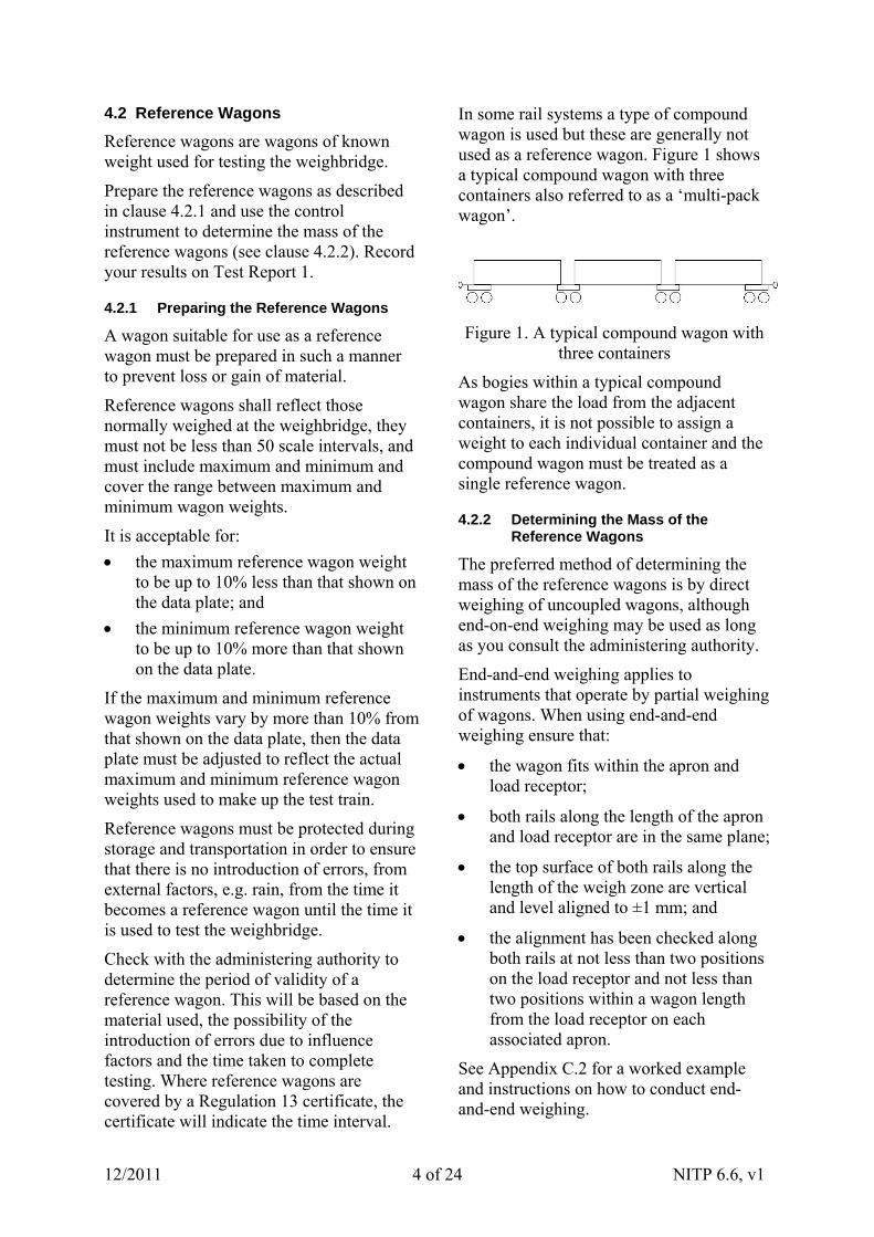
In some rail systems a type of compound wagon is used but these are generally not used as a reference wagon. Figure 1 shows a typical compound wagon with three containers also referred to as a ‘multi-pack wagon’.
Figure 1. A typical compound wagon with three containers
As bogies within a typical compound wagon share the load from the adjacent containers, it is not possible to assign a weight to each individual container and the compound wagon must be treated as a single reference wagon.
4.2.2 Determining the Mass of the Reference Wagons
The preferred method of determining the mass of the reference wagons is by direct weighing of uncoupled wagons, although end-on-end weighing may be used as long as you consult the administering authority.
End-and-end weighing applies to instruments that operate by partial weighing of wagons. When using end-and-end weighing ensure that:
the wagon fits within the apron and load receptor;
both rails along the length of the apron and load receptor are in the same plane;
the top surface of both rails along the length of the weigh zone are vertical and level aligned to ±1 mm; and
the alignment has been checked along both rails at not less than two positions on the load receptor and not less than two positions within a wagon length from the load receptor on each associated apron.
See Appendix C.2 for a worked example and instructions on how to conduct end-and-end weighing.
12/2011 NITP 6.6, v1 4 of 24
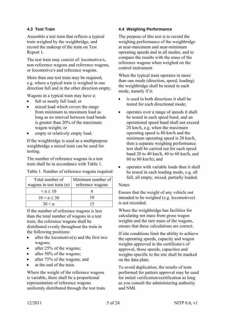
4.3 Test Train
Assemble a test train that reflects a typical train weighed by the weighbridge, and record the makeup of the train on Test Report 1.
The test train may consist of: locomotive/s, non-reference wagons and reference wagons, or locomotive/s and reference wagons.
More than one test train may be required, e.g. where a typical train is weighed in one direction full and in the other direction empty.
Wagons in a typical train may have a: full or nearly full load; or mixed load which covers the range
from minimum to maximum load as long as no interval between load bands is greater than 20% of the maximum wagon weight; or
empty or relatively empty load.
If the weighbridge is used as a multipurpose weighbridge a mixed train can be used for testing.
The number of reference wagons in a test train shall be in accordance with Table 1.
Table 1. Number of reference wagons required
Total number of wagons in test train (n)
Minimum number of reference wagons
< n 10 n
10 < n 30 10
30 < n 15
If the number of reference wagons is less than the total number of wagons in a test train, the reference wagons shall be distributed evenly throughout the train in the following positions: after the locomotive(s) and the first two
wagons; after 25% of the wagons; after 50% of the wagons; after 75% of the wagons; and at the end of the train.
Where the weight of the reference wagons is variable, there shall be a proportional representation of reference wagons uniformly distributed through the test train.
4.4 Weighing Performance
The purpose of this test is to record the weighing performance of the weighbridge at near-maximum and near-minimum operating speeds and in all modes, and to compare the results with the mass of the reference wagons when weighed on the control instrument.
When the typical train operates in more than one mode (direction, speed, loading) the weighbridge shall be tested in each mode, namely if it:
is used in both directions it shall be tested for each directional mode;
operates over a range of speeds it shall be tested in each speed band, and an operational speed band shall not exceed 20 km/h, e.g. when the maximum operating speed is 80 km/h and the minimum operating speed is 20 km/h, then a separate weighing performance test shall be carried out for each speed band 20 to 40 km/h, 40 to 60 km/h, and 60 to 80 km/h); and
operates with variable loads then it shall be tested in each loading mode, e.g. all full, all empty, mixed, partially loaded.
Notes:
Ensure that the weight of any vehicle not intended to be weighed (e.g. locomotives) is not recorded.
Where the weighbridge has facilities for calculating net mass from gross wagon weights and the tare mass of the wagons, ensure that these calculations are correct.
If site conditions limit the ability to achieve the operating speeds, capacity and wagon weights approved in the certificate/s of approval, those speeds, capacities and weights specific to the site shall be marked on the data plate.
To avoid duplication, the results of tests performed for pattern approval may be used for initial verification/certification as long as you consult the administering authority and NMI.
12/2011 NITP 6.6, v1 5 of 24
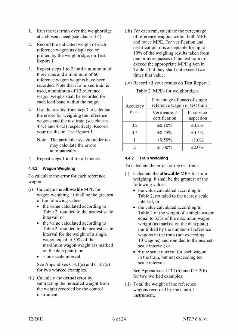
1. Run the test train over the weighbridge at a chosen speed (see clause 4.4).
2. Record the indicated weight of each reference wagon as displayed or printed by the weighbridge, on Test Report 1.
3. Repeat steps 1 to 2 until a minimum of three runs and a minimum of 60 reference wagon weights have been recorded. Note that if a mixed train is used, a minimum of 12 reference wagon weighs shall be recorded for each load band within the range.
4. Use the results from step 3 to calculate the errors for weighing the reference wagons and the test train (see clauses 4.4.1 and 4.4.2) respectively. Record your results on Test Report 1.
Note: The particular system under test may calculate the errors automatically.
5. Repeat steps 1 to 4 for all modes.
4.4.1 Wagon Weighing
To calculate the error for each reference wagon:
(i) Calculate the allowable MPE for wagon weighing. It shall be the greatest of the following values: the value calculated according to
Table 2, rounded to the nearest scale interval; or
the value calculated according to Table 2, rounded to the nearest scale interval for the weight of a single wagon equal to 35% of the maximum wagon weight (as marked on the data plate); or
one scale interval.
See Appendixes C.3.1(a) and C.3.2(a) for two worked examples.
(ii) Calculate the actual error by subtracting the indicated weight from the weight recorded by the control instrument.
(iii) For each run, calculate the percentage of reference wagons within both MPE and twice MPE. For verification and certification, it is acceptable for up to 10% of the weighing results taken from one or more passes of the test train to exceed the appropriate MPE given in Table 2 but they shall not exceed two times that value.
(iv) Record all your results on Test Report 1.
Table 2. MPEs for weighbridges
Percentage of mass of single reference wagon or test train Accuracy
class Verification/ certification
In-service inspection
0.2 ±0.10% ±0.2%
0.5 ±0.25% ±0.5%
1 ±0.50% ±1.0%
2 ±1.00% ±2.0%
4.4.2 Train Weighing
To calculate the error for the test train:
(i) Calculate the allowable MPE for train weighing. It shall be the greatest of the following values: the value calculated according to
Table 2, rounded to the nearest scale interval; or
the value calculated according to Table 2 of the weight of a single wagon equal to 35% of the maximum wagon weight (as marked on the data plate) multiplied by the number of reference wagons in the train (not exceeding 10 wagons) and rounded to the nearest scale interval; or
one scale interval for each wagon in the train, but not exceeding ten scale intervals.
See Appendixes C.3.1(b) and C.3.2(b) for two worked examples.
(ii) Total the weight of the reference wagons recorded by the control instrument.
12/2011 NITP 6.6, v1 6 of 24
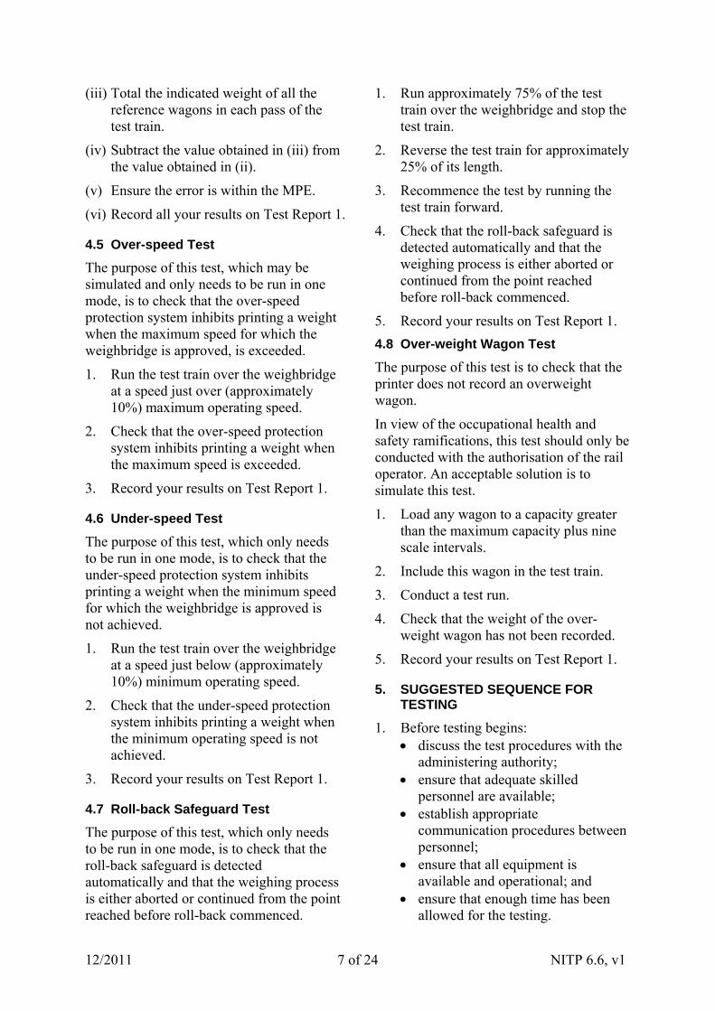
(iii) Total the indicated weight of all the reference wagons in each pass of the test train.
(iv) Subtract the value obtained in (iii) from the value obtained in (ii).
(v) Ensure the error is within the MPE.
(vi) Record all your results on Test Report 1.
4.5 Over-speed Test
The purpose of this test, which may be simulated and only needs to be run in one mode, is to check that the over-speed protection system inhibits printing a weight when the maximum speed for which the weighbridge is approved, is exceeded.
1. Run the test train over the weighbridge at a speed just over (approximately 10%) maximum operating speed.
2. Check that the over-speed protection system inhibits printing a weight when the maximum speed is exceeded.
3. Record your results on Test Report 1.
4.6 Under-speed Test
The purpose of this test, which only needs to be run in one mode, is to check that the under-speed protection system inhibits printing a weight when the minimum speed for which the weighbridge is approved is not achieved.
1. Run the test train over the weighbridge at a speed just below (approximately 10%) minimum operating speed.
2. Check that the under-speed protection system inhibits printing a weight when the minimum operating speed is not achieved.
3. Record your results on Test Report 1.
4.7 Roll-back Safeguard Test
The purpose of this test, which only needs to be run in one mode, is to check that the roll-back safeguard is detected automatically and that the weighing process is either aborted or continued from the point reached before roll-back commenced.
1. Run approximately 75% of the test train over the weighbridge and stop the test train.
2. Reverse the test train for approximately 25% of its length.
3. Recommence the test by running the test train forward.
4. Check that the roll-back safeguard is detected automatically and that the weighing process is either aborted or continued from the point reached before roll-back commenced.
5. Record your results on Test Report 1.
4.8 Over-weight Wagon Test
The purpose of this test is to check that the printer does not record an overweight wagon.
In view of the occupational health and safety ramifications, this test should only be conducted with the authorisation of the rail operator. An acceptable solution is to simulate this test.
1. Load any wagon to a capacity greater than the maximum capacity plus nine scale intervals.
2. Include this wagon in the test train.
3. Conduct a test run.
4. Check that the weight of the over-weight wagon has not been recorded.
5. Record your results on Test Report 1.
5. SUGGESTED SEQUENCE FOR TESTING
1. Before testing begins: discuss the test procedures with the
administering authority; ensure that adequate skilled
personnel are available; establish appropriate
communication procedures between personnel;
ensure that all equipment is available and operational; and
ensure that enough time has been allowed for the testing.
12/2011 NITP 6.6, v1 7 of 24

12/2011 NITP 6.6, v1 8 of 24
Remember to avoid any unnecessary commitment of resources, and to restrict unauthorised access.
2. Check the certificate/s of approval for any additional tests required. Make provision for including these tests in the testing sequence.
3. Visually inspect the weighbridge and record the required details on Test Report 1.
4. Determine if the control instrument is suitable, and meets the accuracy requirements required for it to determine the mass of the reference wagons (see clause 4.1). Record the results on Test Report 2.
5. Test the control instrument for compliance with NITP 6.1 to 6.4 (see clause 4.1) and record the results on Test Report 2.
6. Prepare the reference wagons (see clause 4.2).
7. Use the control instrument to determine the mass of the reference wagons (see clause 4.2) and record the results on Test Report 1.
8. Assemble the test train (see clause 4.3) and record the makeup of the train on Test Report 1.
9. Test the weighing performance of the weighbridge in all modes (see clause 4.4) and record the results (for a minimum of 60 reference wagons over three runs) on Test Report 1.
10. Calculate the allowable MPEs for wagon weighing (see clause 4.4.1(i)) and train weighing (see clause 4.4.2(i)) and record the results on Test Report 1.
11. Calculate the actual errors for wagon weighing (see clause 4.4.1) and train weighing (see clause 4.4.2) and record the results on Test Report 1.
12. Compare the allowable MPEs for wagon weighing and train weighing with the actual errors and record the results on Test Report 1.
13. Test the weighbridge to see if it records over-speed (see clause 4.5) and record the results on Test Report 1.
14. Test the weighbridge to see if it records under-speed (see clause 4.6) and record the results on Test Report 1.
15. Test the weighbridge to see if it detects roll-back (see clauses 4.7) and record the results on Test Report 1.
16. Test the weighbridge to see if it records an over-weight wagon (see clause 4.8) and record the results on Test Report 1.
17. Determine whether the weighbridge has passed or failed. Note: If the weighbridge fails one of
the modes it may still be stamped providing it has passed other modes and the data plate is changed to reflect this.
18. Complete Test Report 1 and Test Report 2.
19. Carry out anything else you need to do to complete the procedure. This may include:
obliterating verification, certification and control marks from the weighbridge; and
stamping the weighbridge (for more information on stamping see General Information for Test Procedures).
APPENDIX A. TEST REPORTS
Appendix A contains two test reports: Test Report 1 is for weighbridges; and Test Report 2 is for control instruments.
Although the format of the test reports may vary according to the individual needs and requirements of trade measurement authorities and licensees, the following test reports contains the minimum amount of information that must be recorded.
If the certificate/s of approval requires additional tests, attach pages that record the results of these tests.
Number each page of the test report in the style shown at the top of each page.
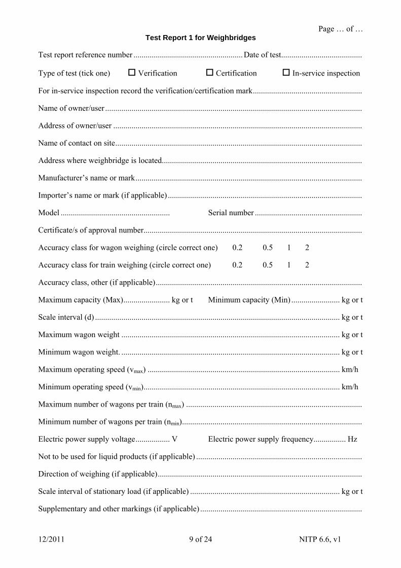
Page … of … Test Report 1 for Weighbridges
12/2011 NITP 6.6, v1 9 of 24
Test report reference number ......................................................Date of test........................................
Type of test (tick one) Verification Certification In-service inspection
For in-service inspection record the verification/certification mark......................................................
Name of owner/user ...............................................................................................................................
Address of owner/user ...........................................................................................................................
Name of contact on site..........................................................................................................................
Address where weighbridge is located...................................................................................................
Manufacturer’s name or mark................................................................................................................
Importer’s name or mark (if applicable) ................................................................................................
Model ...................................................... Serial number .....................................................
Certificate/s of approval number............................................................................................................
Accuracy class for wagon weighing (circle correct one) 0.2 0.5 1 2
Accuracy class for train weighing (circle correct one) 0.2 0.5 1 2
Accuracy class, other (if applicable)......................................................................................................
Maximum capacity (Max)....................... kg or t Minimum capacity (Min) ........................ kg or t
Scale interval (d) ......................................................................................................................... kg or t
Maximum wagon weight ............................................................................................................ kg or t
Minimum wagon weight. ............................................................................................................ kg or t
Maximum operating speed (vmax) ............................................................................................... km/h
Minimum operating speed (vmin)................................................................................................. km/h
Maximum number of wagons per train (nmax) .......................................................................................
Minimum number of wagons per train (nmin).........................................................................................
Electric power supply voltage................. V Electric power supply frequency................ Hz
Not to be used for liquid products (if applicable) ..................................................................................
Direction of weighing (if applicable).....................................................................................................
Scale interval of stationary load (if applicable) .......................................................................... kg or t
Supplementary and other markings (if applicable) ................................................................................

Page … of … Test Report 1 for Weighbridges
12/2011 NITP 6.6, v1 10 of 24
Does the weighbridge comply with its certificate/s of approval? yes/no
Is the weighbridge used in accordance with its certificate/s of approval? yes/no
Are all mandatory descriptive markings clearly and permanently marked on data plate? yes/no
Is the weighbridge in a suitable operational condition? yes/no
Are there any apparent obstructions to the operation of the weighbridge? yes/no
Is the indicating device accessible during normal operation? yes/no
Is the headwork protected against any other influence likely to affect its performance? yes/no
For the rail line in continuous systems — are the approaches and departures: securely fixed to the railway sleepers, surveyed regularly to confirm the vertical deflection is not excessive, and tamped if survey shows vertical deflection to be excessive?
yes/no/na
For the rail line in continuous systems — are the rail sleeper spacings positioned to specifications in relation to the transducers?
yes/no/na
For the rail line in continuous systems — is there at least 20 mm clearance between the transducer rail and ballast?
yes/no/na
For the rail line in non-continuous systems — are the approaches and departures in the same plane as the weighbridge?
yes/no/na
For the rail line in non-continuous systems — are the approaches and departures in the same plane as the weighbridge?
yes/no/na
For the rail line in non-continuous systems — are the rail lines positioned such that there is no excessive space between the live and dead rails?
yes/no/na
Are the rail sleeper spacings positioned to specifications in relation to the transducers? yes/no/na
Is there at least 20 mm clearance between the transducer rail and ballast? yes/no/na
For additional indicating devices: do they exactly repeat the information on the primary indication and does any device for price computation and/or ticket/label printing comply with the requirements of the General Supplementary Certificates S1/0/A or S1/0?
yes/no/na
Page … of … Test Report 1 for Weighbridges
12/2011 NITP 6.6, v1 11 of 24
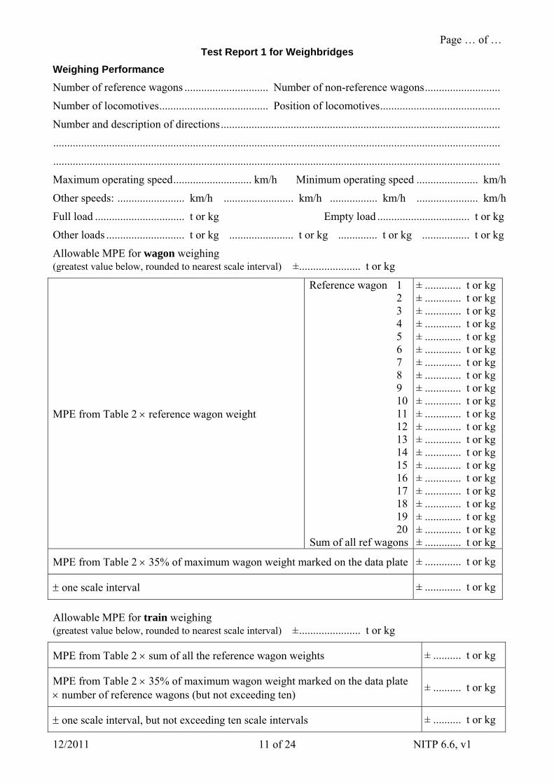
Weighing Performance
Number of reference wagons .............................. Number of non-reference wagons...........................
Number of locomotives....................................... Position of locomotives...........................................
Number and description of directions....................................................................................................
................................................................................................................................................................
................................................................................................................................................................
Maximum operating speed............................ km/h Minimum operating speed ...................... km/h
Other speeds: ........................ km/h ......................... km/h ................. km/h ...................... km/h
Full load ................................ t or kg Empty load ................................. t or kg
Other loads ............................ t or kg ....................... t or kg .............. t or kg ................. t or kg
Allowable MPE for wagon weighing (greatest value below, rounded to nearest scale interval) ±...................... t or kg
MPE from Table 2 reference wagon weight
Reference wagon 1 2 3 4 5 6 7 8 9 10 11 12 13 14 15 16 17 18 19 20 Sum of all ref wagons
± ............. t or kg ± ............. t or kg ± ............. t or kg ± ............. t or kg ± ............. t or kg ± ............. t or kg ± ............. t or kg ± ............. t or kg ± ............. t or kg ± ............. t or kg ± ............. t or kg ± ............. t or kg ± ............. t or kg ± ............. t or kg ± ............. t or kg ± ............. t or kg ± ............. t or kg ± ............. t or kg ± ............. t or kg ± ............. t or kg ± ............. t or kg
MPE from Table 2 35% of maximum wagon weight marked on the data plate ± ............. t or kg
one scale interval ± ............. t or kg
Allowable MPE for train weighing (greatest value below, rounded to nearest scale interval) ±...................... t or kg
MPE from Table 2 sum of all the reference wagon weights ± .......... t or kg
MPE from Table 2 35% of maximum wagon weight marked on the data plate number of reference wagons (but not exceeding ten)
± .......... t or kg
one scale interval, but not exceeding ten scale intervals ± .......... t or kg
Page … of … Test Report 1 for Weighbridges
12/2011 NITP 6.6, v1 12 of 24
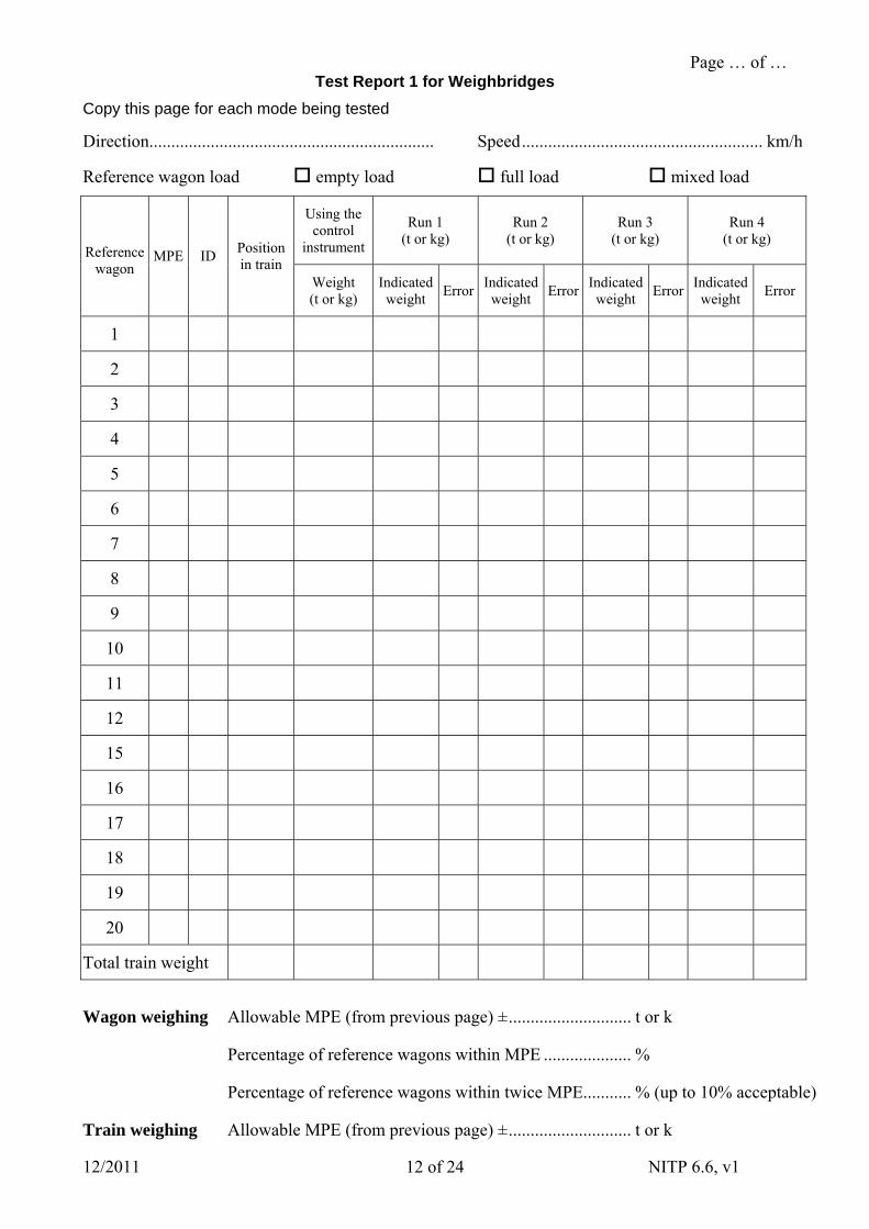
Copy this page for each mode being tested
Direction................................................................. Speed....................................................... km/h
Reference wagon load empty load full load mixed load
Using the control
instrument
Run 1 (t or kg)
Run 2 (t or kg)
Run 3 (t or kg)
Run 4 (t or kg)
Reference wagon
MPE ID Position in train
Weight (t or kg)
Indicated weight
ErrorIndicated weight
ErrorIndicated weight
Error Indicated weight
Error
1
2
3
4
5
6
7
8
9
10
11
12
15
16
17
18
19
20
Total train weight
Wagon weighing Allowable MPE (from previous page) ±............................ t or k
Percentage of reference wagons within MPE .................... %
Percentage of reference wagons within twice MPE........... % (up to 10% acceptable)
Train weighing Allowable MPE (from previous page) ±............................ t or k
Page … of … Test Report 1 for Weighbridges
12/2011 NITP 6.6, v1 13 of 24
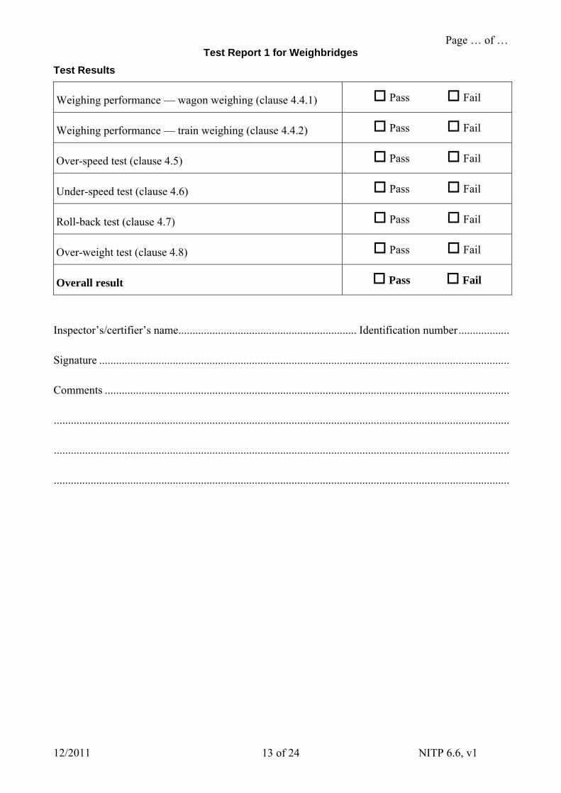
Test Results
Weighing performance — wagon weighing (clause 4.4.1) Pass Fail
Weighing performance — train weighing (clause 4.4.2) Pass Fail
Over-speed test (clause 4.5) Pass Fail
Under-speed test (clause 4.6) Pass Fail
Roll-back test (clause 4.7) Pass Fail
Over-weight test (clause 4.8) Pass Fail
Overall result Pass Fail
Inspector’s/certifier’s name............................................................... Identification number..................
Signature .................................................................................................................................................
Comments ...............................................................................................................................................
.................................................................................................................................................................
.................................................................................................................................................................
.................................................................................................................................................................
Page … of … Test Report 2 for Control Instruments
12/2011 NITP 6.6, v1 14 of 24
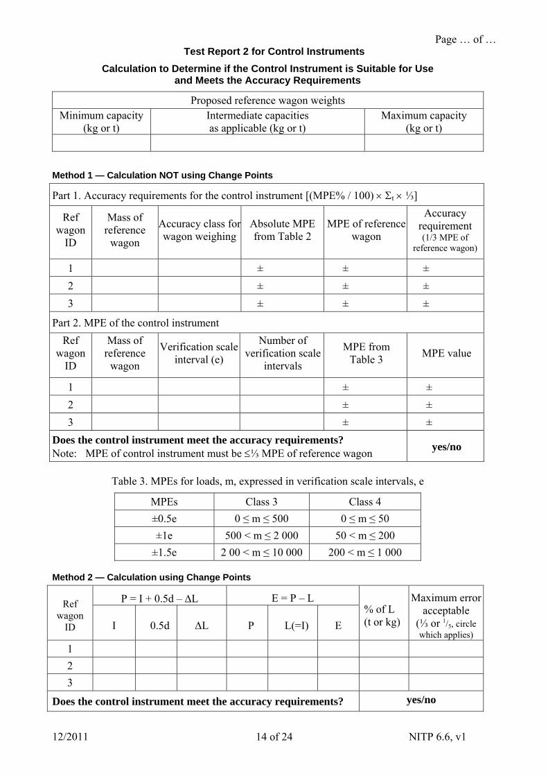
Calculation to Determine if the Control Instrument is Suitable for Use and Meets the Accuracy Requirements
Proposed reference wagon weights Minimum capacity
(kg or t) Intermediate capacities as applicable (kg or t)
Maximum capacity (kg or t)
Method 1 — Calculation NOT using Change Points
Part 1. Accuracy requirements for the control instrument [(MPE% / 100) t ⅓]
Ref wagon
ID
Mass of reference
wagon
Accuracy class for wagon weighing
Absolute MPE from Table 2
MPE of reference wagon
Accuracy requirement (1/3 MPE of
reference wagon)
1 ± ± ±
2 ± ± ±
3 ± ± ±
Part 2. MPE of the control instrument
Ref wagon
ID
Mass of reference
wagon
Verification scale interval (e)
Number of verification scale
intervals
MPE from Table 3
MPE value
1 ± ±
2 ± ±
3 ± ±
Does the control instrument meet the accuracy requirements? Note: MPE of control instrument must be ⅓ MPE of reference wagon
yes/no
Table 3. MPEs for loads, m, expressed in verification scale intervals, e
MPEs Class 3 Class 4
±0.5e 0 ≤ m ≤ 500 0 ≤ m ≤ 50
±1e 500 < m ≤ 2 000 50 < m ≤ 200
±1.5e 2 00 < m ≤ 10 000 200 < m ≤ 1 000
Method 2 — Calculation using Change Points
P = I + 0.5d – L E = P – L Ref wagon
ID I 0.5d ΔL P L(=I) E
% of L (t or kg)
Maximum error acceptable
(⅓ or 1/5, circle which applies)
1
2
3
Does the control instrument meet the accuracy requirements? yes/no
Page … of … Test Report 2 for Control Instruments
12/2011 NITP 6.6, v1 15 of 24
Refer to NITP 6.1 to 6.4 for the test procedure
Test report reference number ......................................................Date of test........................................
Type of test (tick one) Verification Certification
Other (attach either a 6B/0 analysis or a letter of approval from NMI)
Name of owner/user ...............................................................................................................................
Address of owner/user ...........................................................................................................................
Name of contact on premises .................................................................................................................
Address where instrument located .........................................................................................................
Description of instrument.......................................................................................................................
Manufacturer/s ............................ Model ........................ Instrument serial number .............................
Certificate/s of approval number (if applicable) ....................................................................................
Maximum capacity (Max).......................... Minimum capacity (Min) ..................................................
Verification scale interval (e)........................................Accuracy class ................................................
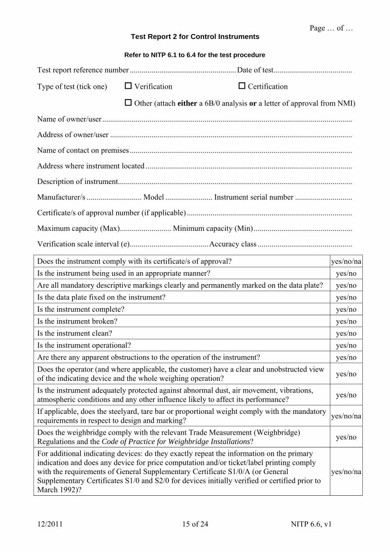
Does the instrument comply with its certificate/s of approval? yes/no/na
Is the instrument being used in an appropriate manner? yes/no
Are all mandatory descriptive markings clearly and permanently marked on the data plate? yes/no
Is the data plate fixed on the instrument? yes/no
Is the instrument complete? yes/no
Is the instrument broken? yes/no
Is the instrument clean? yes/no
Is the instrument operational? yes/no
Are there any apparent obstructions to the operation of the instrument? yes/no
Does the operator (and where applicable, the customer) have a clear and unobstructed view of the indicating device and the whole weighing operation?
yes/no
Is the instrument adequately protected against abnormal dust, air movement, vibrations, atmospheric conditions and any other influence likely to affect its performance?
yes/no
If applicable, does the steelyard, tare bar or proportional weight comply with the mandatory requirements in respect to design and marking?
yes/no/na
Does the weighbridge comply with the relevant Trade Measurement (Weighbridge) Regulations and the Code of Practice for Weighbridge Installations?
yes/no
For additional indicating devices: do they exactly repeat the information on the primary indication and does any device for price computation and/or ticket/label printing comply with the requirements of General Supplementary Certificate S1/0/A (or General Supplementary Certificates S1/0 and S2/0 for devices initially verified or certified prior to March 1992)?
yes/no/na
Page … of … Test Report 2 for Control Instruments
12/2011 NITP 6.6, v1 16 of 24
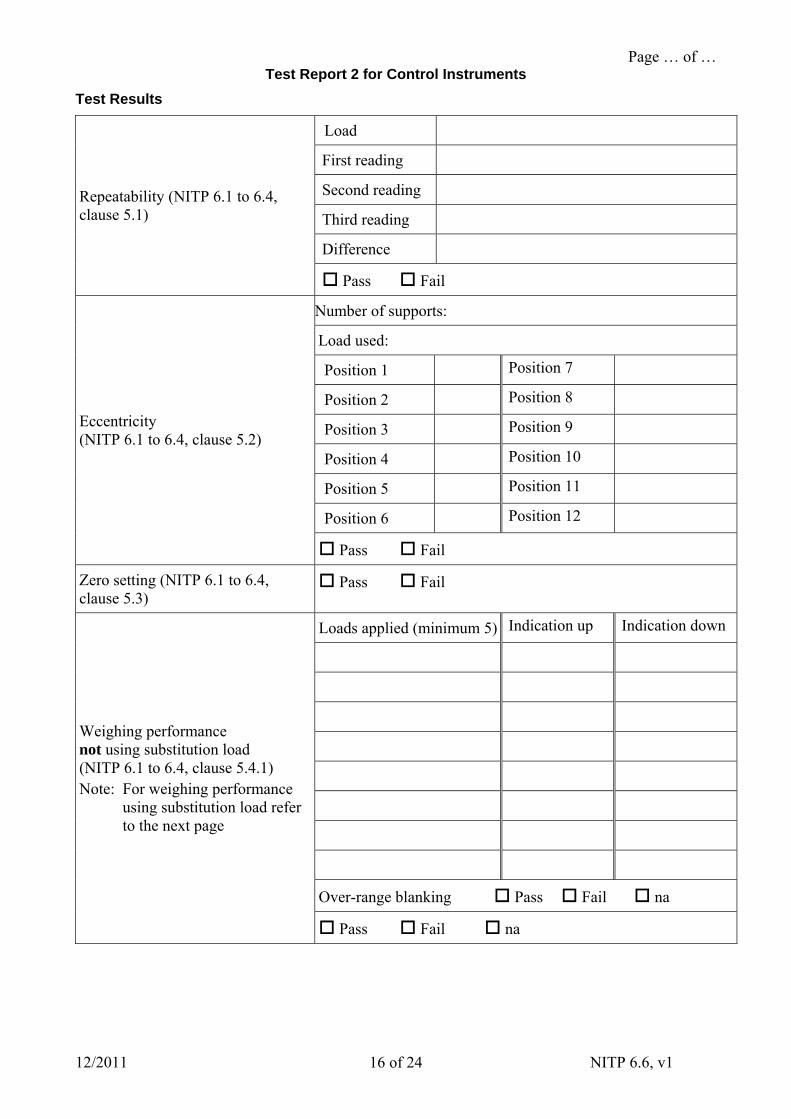
Test Results
Load
First reading
Second reading
Third reading
Difference
Repeatability (NITP 6.1 to 6.4, clause 5.1)
Pass Fail
Number of supports:
Load used:
Position 1 Position 7
Position 2 Position 8
Position 3 Position 9
Position 4 Position 10
Position 5 Position 11
Position 6 Position 12
Eccentricity (NITP 6.1 to 6.4, clause 5.2)
Pass Fail
Zero setting (NITP 6.1 to 6.4, clause 5.3)
Pass Fail
Loads applied (minimum 5) Indication up Indication down
Over-range blanking Pass Fail na
Weighing performance not using substitution load (NITP 6.1 to 6.4, clause 5.4.1) Note: For weighing performance
using substitution load refer to the next page
Pass Fail na
Page … of … Test Report 2 for Control Instruments
12/2011 NITP 6.6, v1 17 of 24
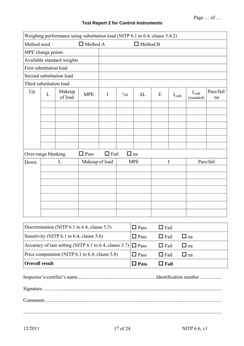
Weighing performance using substitution load (NITP 6.1 to 6.4, clause 5.4.2)
Method used Method A Method B
MPE change points
Available standard weights
First substitution load
Second substitution load
Third substitution load
L Makeup of load
MPE I ½e ΔL E Lsub Lsub
(rounded)
Pass/fail/na
Up
Over-range blanking Pass Fail na
L Makeup of load MPE I Pass/fail
Down
Discrimination (NITP 6.1 to 6.4, clause 5.5) Pass Fail
Sensitivity (NITP 6.1 to 6.4, clause 5.6) Pass Fail na
Accuracy of tare setting (NITP 6.1 to 6.4, clause 5.7) Pass Fail na
Price computation (NITP 6.1 to 6.4, clause 5.8) Pass Fail na
Overall result Pass Fail
Inspector’s/certifier’s name............................................................... Identification number..................
Signature .................................................................................................................................................
Comments ...............................................................................................................................................
.................................................................................................................................................................
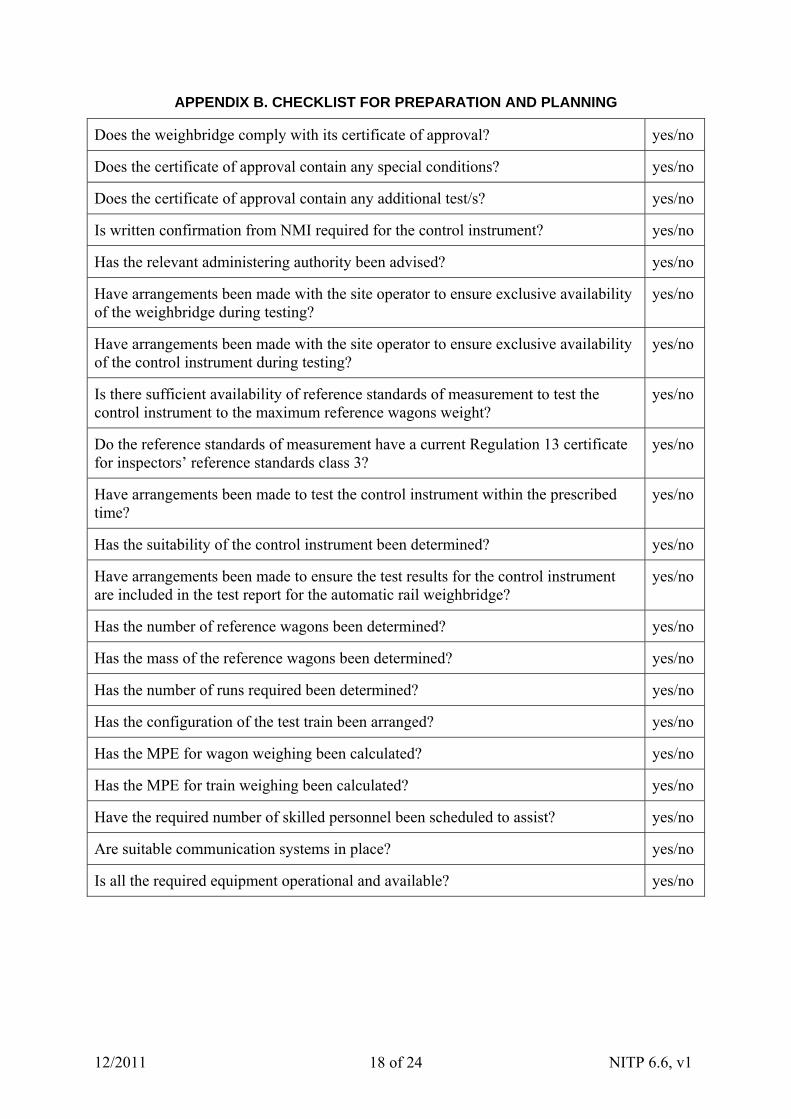
APPENDIX B. CHECKLIST FOR PREPARATION AND PLANNING
Does the weighbridge comply with its certificate of approval? yes/no
Does the certificate of approval contain any special conditions? yes/no
Does the certificate of approval contain any additional test/s? yes/no
Is written confirmation from NMI required for the control instrument? yes/no
Has the relevant administering authority been advised? yes/no
Have arrangements been made with the site operator to ensure exclusive availability of the weighbridge during testing?
yes/no
Have arrangements been made with the site operator to ensure exclusive availability of the control instrument during testing?
yes/no
Is there sufficient availability of reference standards of measurement to test the control instrument to the maximum reference wagons weight?
yes/no
Do the reference standards of measurement have a current Regulation 13 certificate for inspectors’ reference standards class 3?
yes/no
Have arrangements been made to test the control instrument within the prescribed time?
yes/no
Has the suitability of the control instrument been determined? yes/no
Have arrangements been made to ensure the test results for the control instrument are included in the test report for the automatic rail weighbridge?
yes/no
Has the number of reference wagons been determined? yes/no
Has the mass of the reference wagons been determined? yes/no
Has the number of runs required been determined? yes/no
Has the configuration of the test train been arranged? yes/no
Has the MPE for wagon weighing been calculated? yes/no
Has the MPE for train weighing been calculated? yes/no
Have the required number of skilled personnel been scheduled to assist? yes/no
Are suitable communication systems in place? yes/no
Is all the required equipment operational and available? yes/no
12/2011 NITP 6.6, v1 18 of 24
12/2011 NITP 6.6, v1 19 of 24
APPENDIX C. WORKED EXAMPLES
C.1 How to Determine the Suitability of the Control Instrument
In this example the weighbridge has maximum wagon weight of 80 000 kg and a minimum wagon weight of 18 000 kg. The weighbridge is also capable of being used as a non-automatic weighbridge.
The non-automatic weighbridge has a capacity of 100 000 t with a verification scale interval of 50 kg. It will be tested within 24 hours and can be used as the control instrument provided it meets the accuracy requirements. The accuracy class of the control instrument is class 3.
The reference wagon weights used are 18 000 kg and 78 000 kg. The accuracy class for wagon weighing of the weighbridge is 0.5 (MPE of ±0.25%).
In this case, the maximum error acceptable for the control instrument must be equal to or less than one-third the MPE value of the reference wagon. This accuracy only applies when the weighbridge is used as the control instrument and the preparation of the reference wagons is commenced within 24 hours of testing the control instrument.
This example provides two different methods to determine the suitability of the control instrument. If method 1 does not show the control instrument is suitable then method 2 can be employed to ensure the control instrument is suitable.
C.1.1 Method 1 — Calculation NOT using Change Points
If this method determines the control instrument is suitable for both high and low capacity reference wagons it will also be suitable for all reference wagons within the range. The weighing results for each reference wagon are taken directly from the indication of the control instrument without the need to use change points as described in method 2.
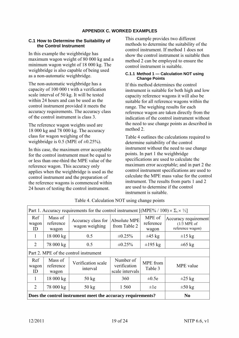
Table 4 outlines the calculations required to determine suitability of the control instrument without the need to use change points. In part 1 the weighbridge specifications are used to calculate the maximum error acceptable; and in part 2 the control instrument specifications are used to calculate the MPE mass value for the control instrument. The results from parts 1 and 2 are used to determine if the control instrument is suitable.
Table 4. Calculation NOT using change points
Part 1. Accuracy requirements for the control instrument [(MPE% / 100) t ⅓]
Ref wagon
ID
Mass of reference
wagon
Accuracy class for wagon weighing
Absolute MPE from Table 2
MPE of reference
wagon
Accuracy requirement(1/3 MPE of
reference wagon)
1 18 000 kg 0.5 ±0.25% ±45 kg ±15 kg
2 78 000 kg 0.5 ±0.25% ±195 kg ±65 kg
Part 2. MPE of the control instrument
Ref wagon
ID
Mass of reference
wagon
Verification scale interval
Number of verification
scale intervals
MPE from Table 3
MPE value
1 18 000 kg 50 kg 360 ±0.5e ±25 kg
2 78 000 kg 50 kg 1 560 ±1e ±50 kg
Does the control instrument meet the accuracy requirements? No
The calculations in Table 4 are performed as follows.
In part 1 the mass of the reference wagon is multiplied by the absolute MPE for the weighbridge from Table 2 to give the MPE of the reference wagons. The result is then divided by one-third. This is the maximum error acceptable for the accuracy for the control instrument.
In part 2 the mass of each reference wagon is divided by the verification scale interval to provide the number of verification scale intervals. This is then used to determine the MPE. The MPE is multiplied by the verification scale interval to provide the MPE value for the control instrument at the mass of the reference wagons.
The results in Table 4 are interpreted as follows:
in part 1 for the 18 000 kg reference wagon the accuracy requirement calculated for the control instrument is ±15 kg;
in part 2 at 18 000 kg the MPE of the control instrument is ±25 kg.
Therefore the control instrument is unacceptable as the ±25 kg mass value of the control instrument is greater than the accuracy requirement of ±15 kg for that particular reference wagon.
In part 1 for the 78 000 kg reference wagon the accuracy requirement calculated for the control instrument is ±65 kg.
In part 2 at 78 000 kg the MPE of the control instrument is ±50 kg.
Therefore the control instrument is acceptable as the ±50 kg mass value of the control instrument is less than the accuracy requirement of ±65 kg for that particular reference wagon.
As a result of these calculations the control instrument is only suitable for 78 000 kg reference wagons.
This example demonstrates that where there is significance difference in the mass between low capacity reference wagons and high capacity reference wagons a single interval control instrument may not be suitable. However a multi-interval instrument may have proved to be suitable.
If an 18 000 kg reference wagon is required then the use of change points as shown in method 2 will determine suitability.
C.1.2 Method 2 — Calculation using Change Points
Change points are used to obtain greater resolution of the control instrument when the scale interval of the control instrument does not meet the one-third or one-fifth accuracy requirement.
This example demonstrates how change points can be applied using the same data used in method 1. If change point weights are used they must be used to determine all reference wagons and be recorded as part of the test report. Every reference wagon weighing calculation must show the control instrument is operating within the maximum error acceptable.
The error is determined by following the same basic principal used for substitution load as outlined in NITP 6.1 to 6.4 National Instrument Test Procedures for Non-automatic Weighing Instruments. At a certain load, L, the indicated value, I, is noted.
Additional standard weights of 0.1e are successively added to the load receptor until the indication of the instrument is increased unambiguously by one scale interval (I + e). The total mass of the additional weights is L.
The true indication, P, prior to rounding is found by using the following formula:
P = I + 0.5e – L
The error, E, prior to rounding is E = P – L.
Thus E = (I + 0.5e – L) – L.
For the 18 000 kg reference wagon: after adding successive standard weights of
12/2011 NITP 6.6, v1 20 of 24
12/2011 NITP 6.6, v1 21 of 24
10 kg, the indication changes up 1e from 18 000 kg to 18 050 kg at an additional load of 10 kg. Inserted in the above formula these observations give:
P = (18 000 + 25 – 10) kg = 18 015 kg
Thus the true indication prior to rounding is 18 015 kg and the error is:
E = (18 015 – 18 000) kg = 15 kg
The MPE from Table 2 is ±0.25%. The allowable error for an 18 000 kg reference wagon is:
±0.25% of 18 000 kg = ±45 kg
The accuracy requirement for the control instrument is ±45 ÷ 3 = ±15 kg. Since the error in the control instrument is known and is less than or equal to 15 kg the control instrument is suitable.
For the 78 000 kg reference wagon: after adding successive standard weights of 10 kg, the indication changes up 1e from 78 000 kg to 78 050 kg at an additional load of 20 kg. Inserted in the above formula these observations give:
P = (78 000 + 25 – 20) kg = 78 005 kg
Thus the true indication prior to rounding is 78 005 kg and the error for the control instrument at the mass of the reference wagon is:
E = (78 005 – 78 000) kg = 5 kg
The MPE from Table 2 is ±0.25%. The allowable error for a 78 000 kg reference wagon is:
±0.25% of 78 000 kg = ±195 kg
The accuracy requirement for the control instrument is ±195 ÷ 3 = ±65 kg. Since the error in the control instrument is known and is less than ±65 kg the control instrument is suitable.
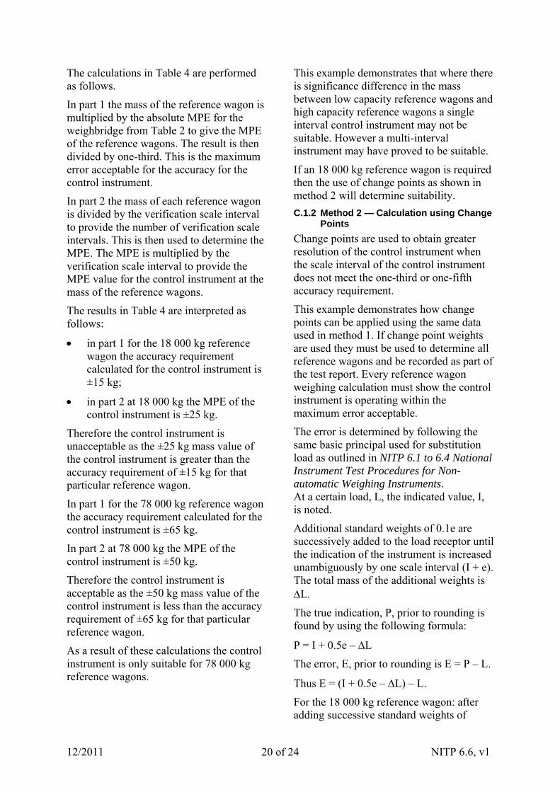
This calculation must be carried out for every wagon weight used in the test. Record results in a table similar to Table 5.
C.2 How to Determine the Mass of Reference Wagons using End-and-End Weighing
1. Weigh each bogie in the centre and at each end of the load receptor and in both directions.
2. Add the six weight indications for direction 1 and divide the result by three.
3. Add the six weight indications for direction 2 and divide the result by three.
4. Add the results obtained in 2 and 3 and divided by two.
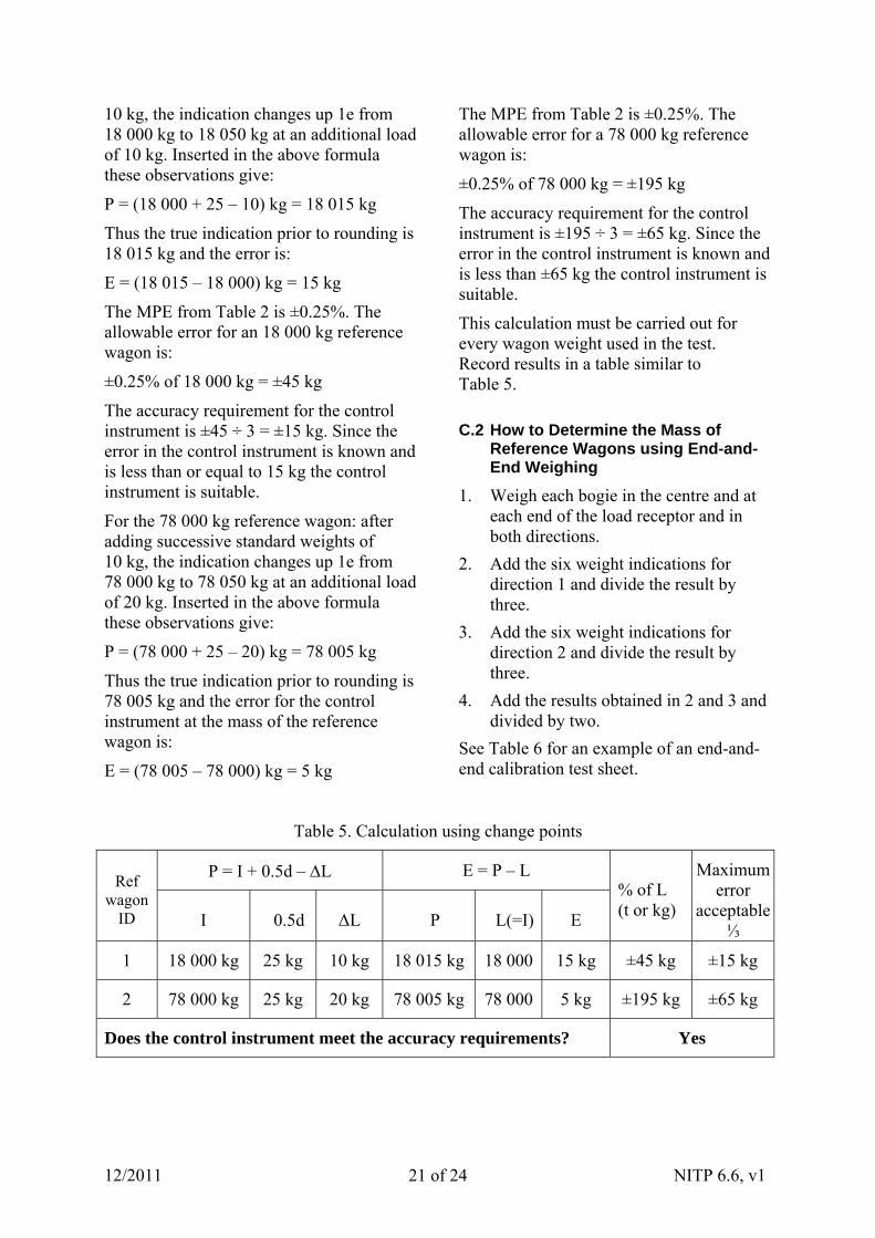
See Table 6 for an example of an end-and-end calibration test sheet.
Table 5. Calculation using change points
P = I + 0.5d – L E = P – L Ref
wagon ID I 0.5d ΔL P L(=I) E
% of L (t or kg)
Maximum error
acceptable⅓
1 18 000 kg 25 kg 10 kg 18 015 kg 18 000 15 kg ±45 kg ±15 kg
2 78 000 kg 25 kg 20 kg 78 005 kg 78 000 5 kg ±195 kg ±65 kg
Does the control instrument meet the accuracy requirements? Yes
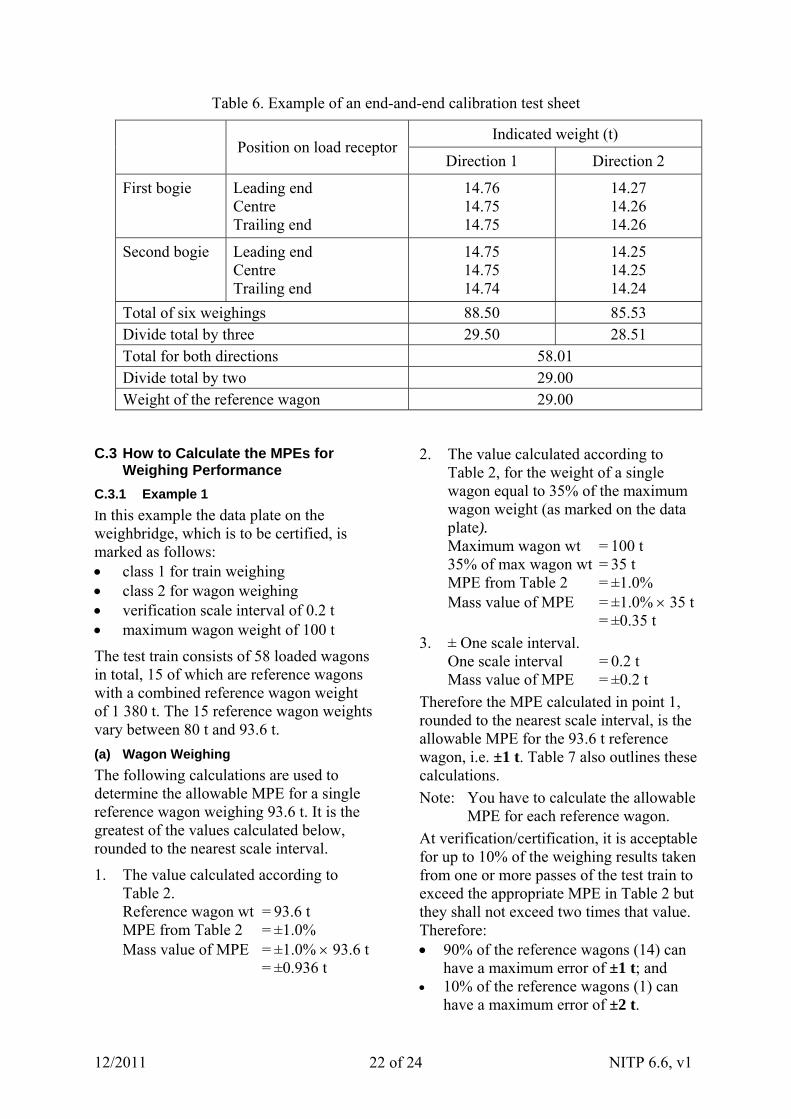
Table 6. Example of an end-and-end calibration test sheet
Indicated weight (t) Position on load receptor
Direction 1 Direction 2
First bogie Leading end Centre Trailing end
14.76 14.75 14.75
14.27 14.26 14.26
Second bogie Leading end Centre Trailing end
14.75 14.75 14.74
14.25 14.25 14.24
Total of six weighings 88.50 85.53 Divide total by three 29.50 28.51 Total for both directions 58.01 Divide total by two 29.00 Weight of the reference wagon 29.00
C.3 How to Calculate the MPEs for Weighing Performance
C.3.1 Example 1
In this example the data plate on the weighbridge, which is to be certified, is marked as follows: class 1 for train weighing class 2 for wagon weighing verification scale interval of 0.2 t maximum wagon weight of 100 t
The test train consists of 58 loaded wagons in total, 15 of which are reference wagons with a combined reference wagon weight of 1 380 t. The 15 reference wagon weights vary between 80 t and 93.6 t.
(a) Wagon Weighing
The following calculations are used to determine the allowable MPE for a single reference wagon weighing 93.6 t. It is the greatest of the values calculated below, rounded to the nearest scale interval.
1. The value calculated according to Table 2. Reference wagon wt = 93.6 t MPE from Table 2 = ±1.0% Mass value of MPE = ±1.0% 93.6 t = ±0.936 t
2. The value calculated according to Table 2, for the weight of a single wagon equal to 35% of the maximum wagon weight (as marked on the data plate). Maximum wagon wt = 100 t 35% of max wagon wt = 35 t MPE from Table 2 = ±1.0% Mass value of MPE = ±1.0% 35 t = ±0.35 t
3. ± One scale interval. One scale interval = 0.2 t Mass value of MPE = ±0.2 t
Therefore the MPE calculated in point 1, rounded to the nearest scale interval, is the allowable MPE for the 93.6 t reference wagon, i.e. ±1 t. Table 7 also outlines these calculations.
Note: You have to calculate the allowable MPE for each reference wagon.
At verification/certification, it is acceptable for up to 10% of the weighing results taken from one or more passes of the test train to exceed the appropriate MPE in Table 2 but they shall not exceed two times that value. Therefore: 90% of the reference wagons (14) can
have a maximum error of ±1 t; and 10% of the reference wagons (1) can
have a maximum error of ±2 t.
12/2011 NITP 6.6, v1 22 of 24
12/2011 NITP 6.6, v1 23 of 24
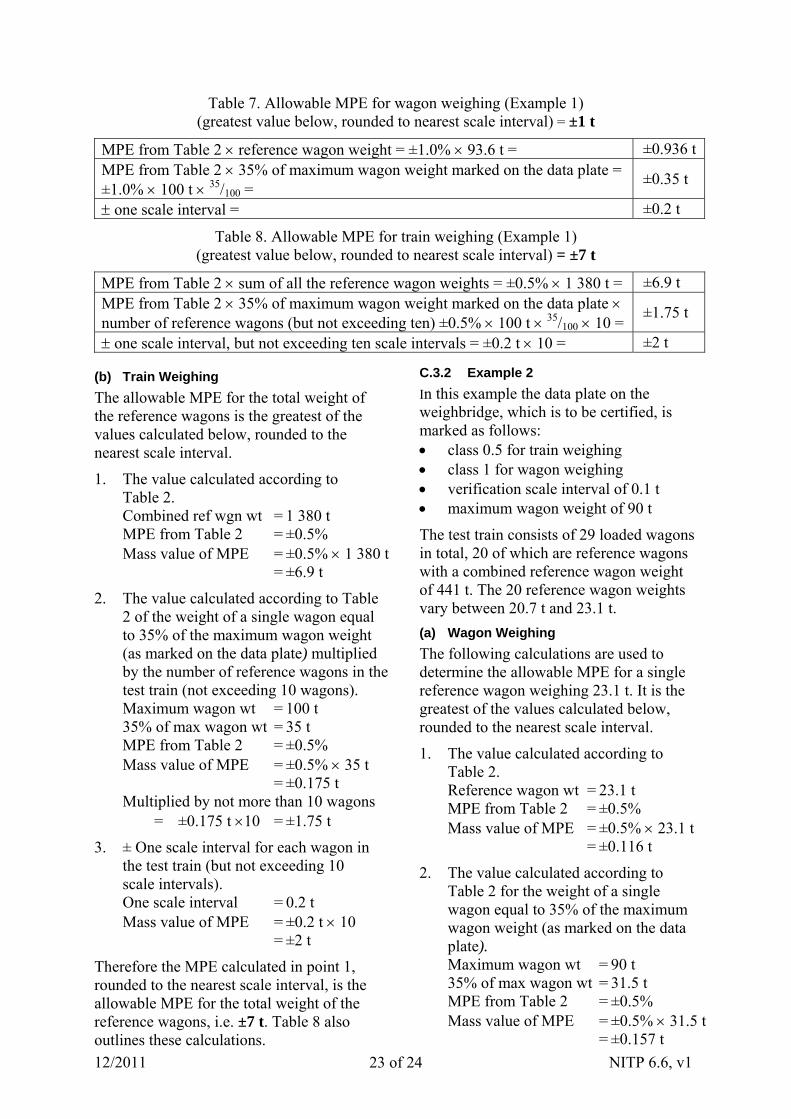
Table 7. Allowable MPE for wagon weighing (Example 1) (greatest value below, rounded to nearest scale interval) = ±1 t
MPE from Table 2 reference wagon weight = ±1.0% 93.6 t = ±0.936 t MPE from Table 2 35% of maximum wagon weight marked on the data plate = ±1.0% 100 t 35/100 =
±0.35 t
one scale interval = ±0.2 t
Table 8. Allowable MPE for train weighing (Example 1) (greatest value below, rounded to nearest scale interval) = ±7 t
MPE from Table 2 sum of all the reference wagon weights = ±0.5% 1 380 t = ±6.9 t MPE from Table 2 35% of maximum wagon weight marked on the data plate number of reference wagons (but not exceeding ten) ±0.5% 100 t 35/100 10 =
±1.75 t
one scale interval, but not exceeding ten scale intervals = ±0.2 t 10 = ±2 t
(b) Train Weighing
The allowable MPE for the total weight of the reference wagons is the greatest of the values calculated below, rounded to the nearest scale interval.
1. The value calculated according to Table 2. Combined ref wgn wt = 1 380 t MPE from Table 2 = ±0.5% Mass value of MPE = ±0.5% 1 380 t = ±6.9 t
2. The value calculated according to Table 2 of the weight of a single wagon equal to 35% of the maximum wagon weight (as marked on the data plate) multiplied by the number of reference wagons in the test train (not exceeding 10 wagons). Maximum wagon wt = 100 t 35% of max wagon wt = 35 t MPE from Table 2 = ±0.5% Mass value of MPE = ±0.5% 35 t = ±0.175 t Multiplied by not more than 10 wagons
= ±0.175 t 10 = ±1.75 t
3. ± One scale interval for each wagon in the test train (but not exceeding 10 scale intervals). One scale interval = 0.2 t Mass value of MPE = ±0.2 t 10 = ±2 t
Therefore the MPE calculated in point 1, rounded to the nearest scale interval, is the allowable MPE for the total weight of the reference wagons, i.e. ±7 t. Table 8 also outlines these calculations.
C.3.2 Example 2
In this example the data plate on the weighbridge, which is to be certified, is marked as follows: class 0.5 for train weighing class 1 for wagon weighing verification scale interval of 0.1 t maximum wagon weight of 90 t
The test train consists of 29 loaded wagons in total, 20 of which are reference wagons with a combined reference wagon weight of 441 t. The 20 reference wagon weights vary between 20.7 t and 23.1 t.
(a) Wagon Weighing
The following calculations are used to determine the allowable MPE for a single reference wagon weighing 23.1 t. It is the greatest of the values calculated below, rounded to the nearest scale interval.
1. The value calculated according to Table 2. Reference wagon wt = 23.1 t MPE from Table 2 = ±0.5% Mass value of MPE = ±0.5% 23.1 t = ±0.116 t
2. The value calculated according to Table 2 for the weight of a single wagon equal to 35% of the maximum wagon weight (as marked on the data plate). Maximum wagon wt = 90 t 35% of max wagon wt = 31.5 t MPE from Table 2 = ±0.5% Mass value of MPE = ±0.5% 31.5 t = ±0.157 t
12/2011 NITP 6.6, v1 24 of 24
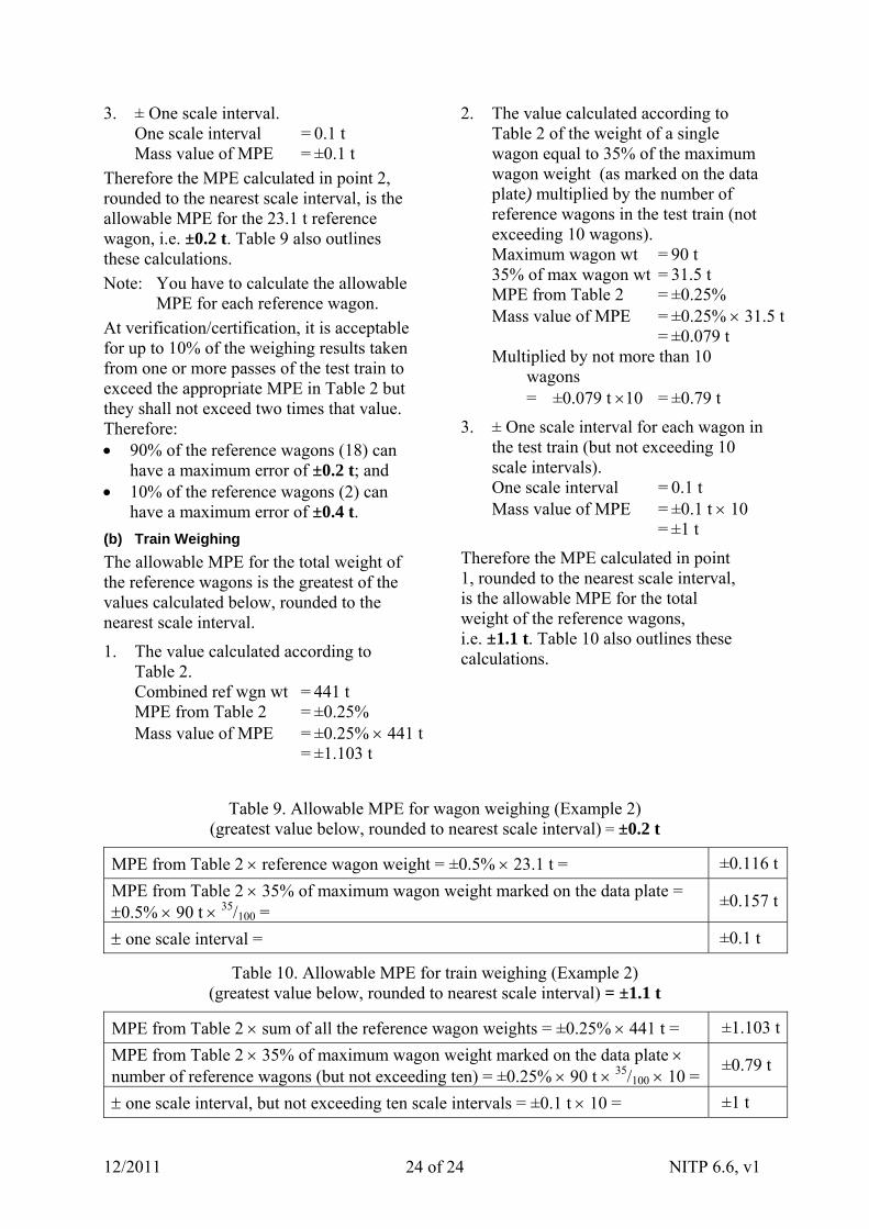
3. ± One scale interval. One scale interval = 0.1 t Mass value of MPE = ±0.1 t
Therefore the MPE calculated in point 2, rounded to the nearest scale interval, is the allowable MPE for the 23.1 t reference wagon, i.e. ±0.2 t. Table 9 also outlines these calculations.
Note: You have to calculate the allowable MPE for each reference wagon.
At verification/certification, it is acceptable for up to 10% of the weighing results taken from one or more passes of the test train to exceed the appropriate MPE in Table 2 but they shall not exceed two times that value. Therefore: 90% of the reference wagons (18) can
have a maximum error of ±0.2 t; and 10% of the reference wagons (2) can
have a maximum error of ±0.4 t.
(b) Train Weighing
The allowable MPE for the total weight of the reference wagons is the greatest of the values calculated below, rounded to the nearest scale interval.
1. The value calculated according to Table 2. Combined ref wgn wt = 441 t MPE from Table 2 = ±0.25% Mass value of MPE = ±0.25% 441 t = ±1.103 t
2. The value calculated according to Table 2 of the weight of a single wagon equal to 35% of the maximum wagon weight (as marked on the data plate) multiplied by the number of reference wagons in the test train (not exceeding 10 wagons). Maximum wagon wt = 90 t 35% of max wagon wt = 31.5 t MPE from Table 2 = ±0.25% Mass value of MPE = ±0.25% 31.5 t = ±0.079 t Multiplied by not more than 10
wagons = ±0.079 t 10 = ±0.79 t
3. ± One scale interval for each wagon in the test train (but not exceeding 10 scale intervals). One scale interval = 0.1 t Mass value of MPE = ±0.1 t 10 = ±1 t
Therefore the MPE calculated in point 1, rounded to the nearest scale interval, is the allowable MPE for the total weight of the reference wagons, i.e. ±1.1 t. Table 10 also outlines these calculations.
Table 9. Allowable MPE for wagon weighing (Example 2) (greatest value below, rounded to nearest scale interval) = ±0.2 t
MPE from Table 2 reference wagon weight = ±0.5% 23.1 t = ±0.116 t
MPE from Table 2 35% of maximum wagon weight marked on the data plate = 0.5% 90 t 35/100 =
±0.157 t
one scale interval = ±0.1 t
Table 10. Allowable MPE for train weighing (Example 2) (greatest value below, rounded to nearest scale interval) = ±1.1 t
MPE from Table 2 sum of all the reference wagon weights = ±0.25% 441 t = ±1.103 t
MPE from Table 2 35% of maximum wagon weight marked on the data plate number of reference wagons (but not exceeding ten) = ±0.25% 90 t 35/100 10 =
±0.79 t
one scale interval, but not exceeding ten scale intervals = ±0.1 t 10 = ±1 t