NIST Experiences with Multipath Ultrasonic Flow Meters for ...
21
NIST Experiences with Multipath Ultrasonic Flow Meters for Stack Applications NIST Workshop Improving Measurement for Smokestack Emissions June 28 and 29, 2017 Gaithersburg, MD Aaron Johnson
Transcript of NIST Experiences with Multipath Ultrasonic Flow Meters for ...
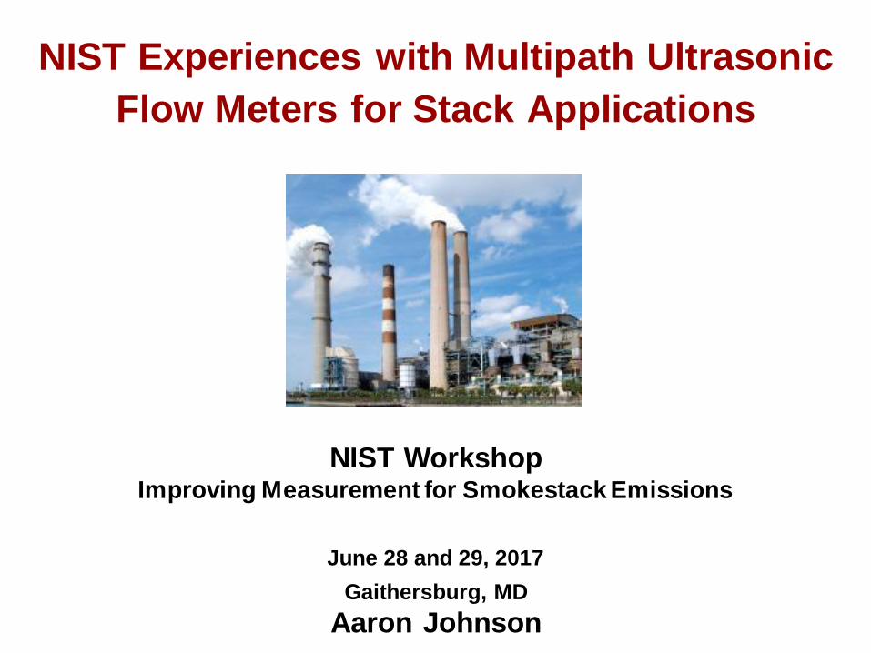
NIST Experiences with Multipath Ultrasonic
Flow Meters for Stack Applications
NIST Workshop Improving Measurement for Smokestack Emissions
June 28 and 29, 2017
Gaithersburg, MD
Aaron Johnson

How accurate can CEMS ultrasonic
flow measurements be made?
• Single path?
• X-pattern?
• Other Multipath Configurations? o 2 path X-pattern Mid Radius
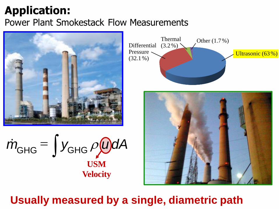
Application: Power Plant Smokestack Flow Measurements
Thermal(3.2 %)Differential
Pressure (32.1%)
Other (1.7 %)
Ultrasonic (63 %)
m& = y r u dAGHG GHG
USM Velocity
Usually measured by a single, diametric path
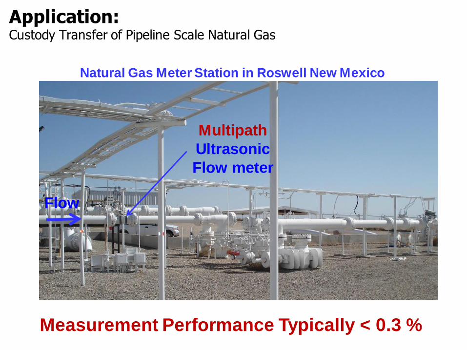
Application: Custody Transfer of Pipeline Scale Natural Gas
Natural Gas Meter Station in Roswell New Mexico
Multipath
Ultrasonic
Flow meter
Flow
Measurement Performance Typically < 0.3 %

Flow is Complicated
Real stacks have swirl and turbulence
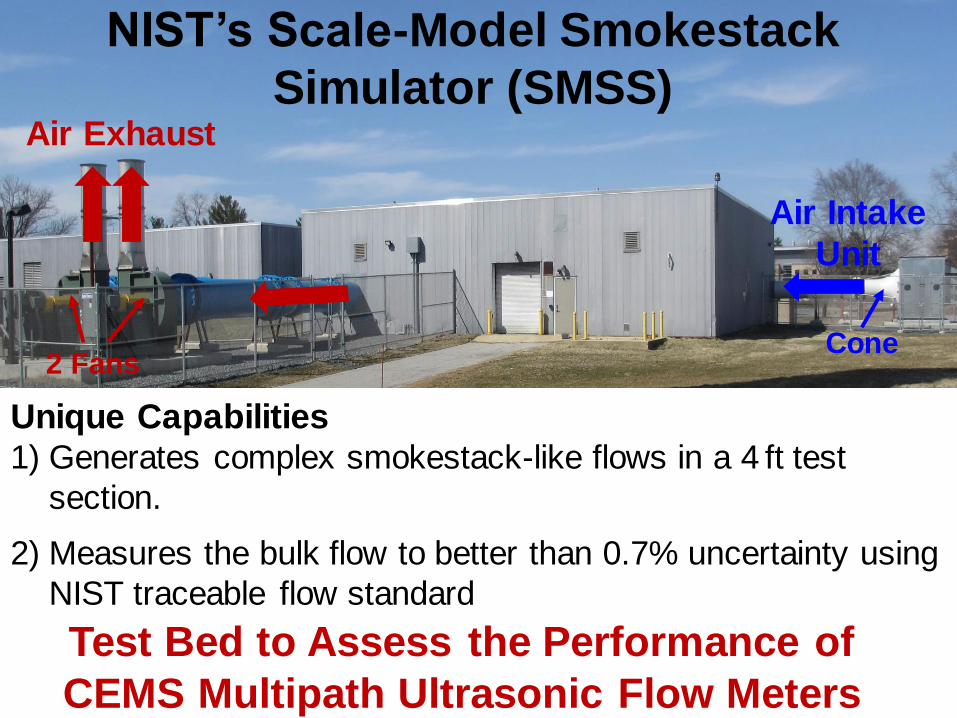
NIST’s Scale-Model Smokestack
Simulator (SMSS)
Air Intake
Unit
Air Exhaust
2 Fans Cone
Unique Capabilities 1) Generates complex smokestack-like flows in a 4 ft test
section.
2) Measures the bulk flow to better than 0.7% uncertainty using
NIST traceable flow standard
Test Bed to Assess the Performance of
CEMS Multipath Ultrasonic Flow Meters
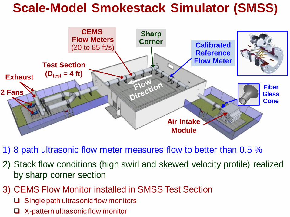
CalibratedReferenceFlow Meter
SharpCorner
Scale-Model Smokestack Simulator (SMSS)
CEMS Sharp Flow Meters Corner
Calibrated (20 to 85 ft/s) Reference Flow Meter
Test Section
= 4 ft)(Dtest Exhaust
Fiber Glass Cone
2 Fans
Air Intake
Module
1) 8 path ultrasonic flow meter measures flow t o better than 0.5 %
2) Stack flow conditions (high swirl and skewed velocity profile) realized
by sharp corner section
3) CEMS Flow Monitor installed in SMSS Test Section
Single path ultrasonic flow monitors
X-pattern ultrasonic flow monitor
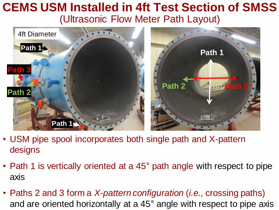
CEMS USM Installed in 4ft Test Section of SMSS (Ultrasonic Flow Meter Path Layout)
Path 1
Path 3 Path 2
Path 1
Path 1
Path 3
Path 2
4ft Diameter
• USM pipe spool incorporates both single path and X-pattern
designs
• Path 1 is vertically oriented at a 45° path angle with respect to pipe
axis
• Paths 2 and 3 form a X-pattern configuration (i.e., crossing paths)
and are oriented horizontally at a 45° angle with respect to pipe axis

Single Path Orientations
0.8
0.9
1.0
1.1
1.2
0 20 40 60 80 100
path
NIST
V
V
NIST [ ft s ]V
Path 3
Path 1
Path 2
Path 2
Path 3
Path 1
• Path orientation significantly affects measurement
3 %
performance (absolute errors range from 5 % to 17 %)
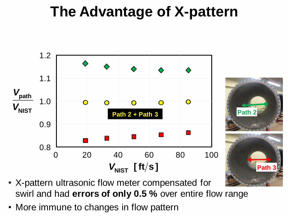
The Advantage of X-pattern
path
NIST
V
V
1.2
1.1
1.0
0.9
0.8 0 20 40 60 80 100
Path 2 + Path 3 Path 2
Path 3 NIST [ ft s ]V
• X-pattern ultrasonic flow meter compensated for swirl
swirl and had errors of only 0.5 % over entire flow range
More immune to changes in flow pattern •
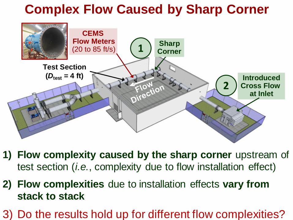
Complex Flow Caused by Sharp Corner
Test Section
(Dtest = 4 ft)
CEMS Flow Meters (20 to 85 ft/s)
Introduced Cross Flow
at Inlet
1 Sharp Corner
2
1) Flow complexity caused by the sharp corner upstream of test section (i.e., complexity due to flow installation effect)
2) Flow complexities due to installation effects vary from stack to stack
3) Do the results hold up for different flow complexities?
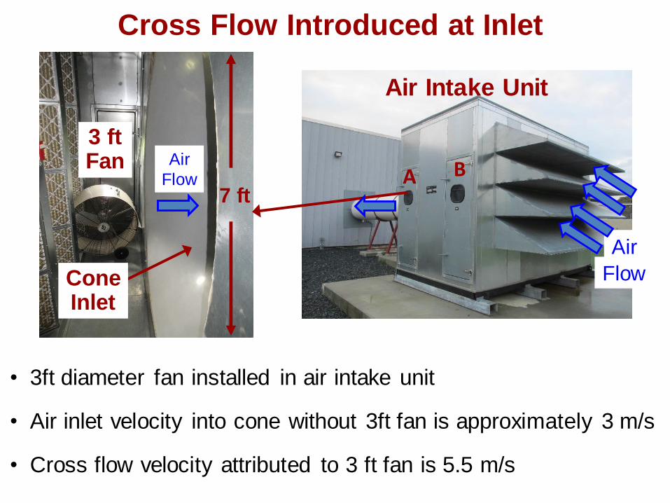
Cross Flow Introduced at Inlet
A
7 ft
3 ft Fan
Cone Inlet
Air
Flow
Air Intake Unit
Air
Flow
A B
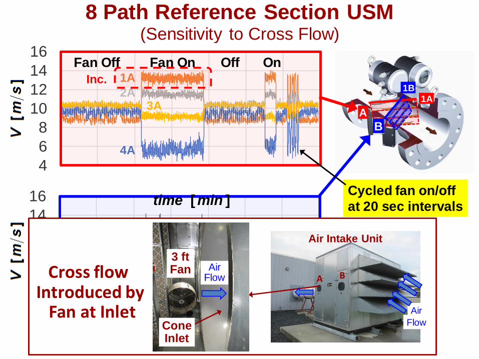
• 3ft diameter fan installed in air intake unit
• Air inlet velocity into cone without 3ft fan is approximately 3 m/s
• Cross flow velocity attributed to 3 ft fan is 5.5 m/s
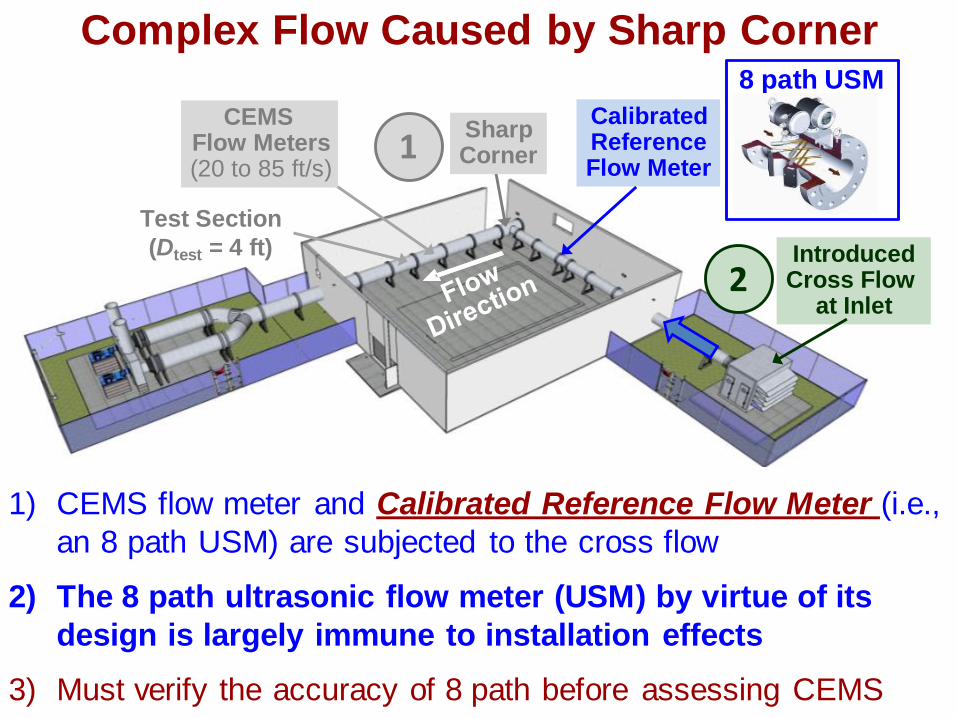
Complex Flow Caused by Sharp Corner
Test Section
(Dtest = 4 ft) Introduced Cross Flow
at Inlet
1 Sharp Corner
2
Calibrated Reference Flow Meter
CEMS Flow Meters (20 to 85 ft/s)
8 path USM
1) CEMS flow meter and Calibrated Reference Flow Meter (i.e.,
an 8 path USM) are subjected to the cross flow
2) The 8 path ultrasonic flow meter (USM) by virtue of its
design is largely immune to installation effects
3) Must verify the accuracy of 8 path before assessing CEMS
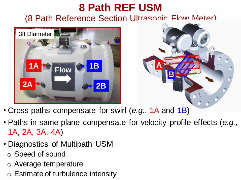
8 Path REF USM (8 Path Reference Section Ultrasonic Flow Meter)
• Cross paths compensate for swirl (e.g., 1A and 1B)
Paths in same plane compensate for velocity profile effects (e.g.,
1A, 2A, 3A, 4A)
Diagnostics of Multipath USM
1A 1B B
A
2A 2B
Flow
3ft Diameter
•
•
o Speed of sound
Average temperature
Estimate of turbulence intensity
o o
1B
2B
3B
4B
Dec.
8 Path Reference Section USM (Sensitivity to Cross Flow)
4
6
8
10
12
14
16
4
6
8
10
12
14
16
0 10 20 30 40 50 60 70
1A
4A
3A
[ ]time min
Fan Off Fan On Off On
4
6
8
10
12
14
16
4
6
8
10
12
14
16
0 10 20 30 40 50 60 70
2A
[ ]time min
A
B
Cycled fan on/off
at 20 sec intervals
Inc.
1A
1B
A
3 ftFan
ConeInlet
AirFlow
Air Intake Unit
Air
Flow
A BCross flow Introduced by
Fan at Inlet
Fan Off
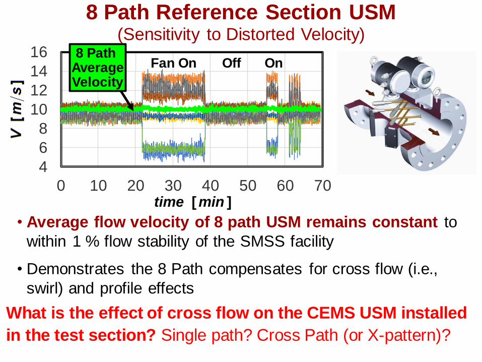
8 Path Reference Section USM (Sensitivity to Distorted Velocity)
4
6
8
10
12
14
16
4
6
8
10
12
14
16
0 10 20 30 40 50 60 70
4
6
8
10
12
14
16
4
6
8
10
12
14
16
0 10 20 30 40 50 60 70
Fan On Off On
[ ]time min
4
6
8
10
12
14
16
4
6
8
10
12
14
16
0 10 20 30 40 50 60 70
8 Path Average Velocity
• Average flow velocity of 8 path USM remains constant to
within 1 % flow stability of the SMSS facility
• Demonstrates the 8 Path compensates for cross flow (i.e.,
swirl) and profile effects
What is the effect of cross flow on the CEMS USM installed
in the test section? Single path? Cross Path (or X-pattern)?
1.04
1.08
1.12
1.16
1.20
1.24
0 10 20 30
1.04
1.08
1.12
1.16
1.20
1.24
0 10 20 30
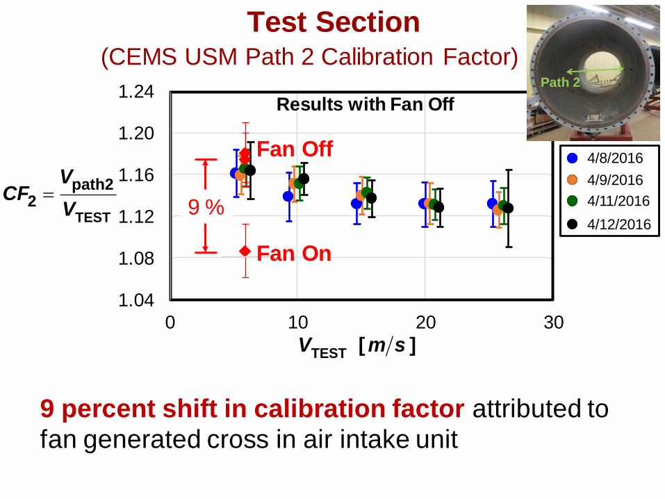
Test Section (CEMS USM Path 2 Calibration Factor)
TEST
path22
VCF
V=
TEST [ ]V m s
Path 2
Fan Off
Fan On
9 %
Results with Fan Off
4/8/2016
4/9/2016
4/11/2016
4/12/2016
9 percent shift in calibration factor attributed to
fan generated cross in air intake unit
0.96
0.98
1.00
1.02
1.04
0 10 20 30
0.96
0.98
1.00
1.02
1.04
0 10 20 30
0.96
0.98
1.00
1.02
1.04
0 10 20 30
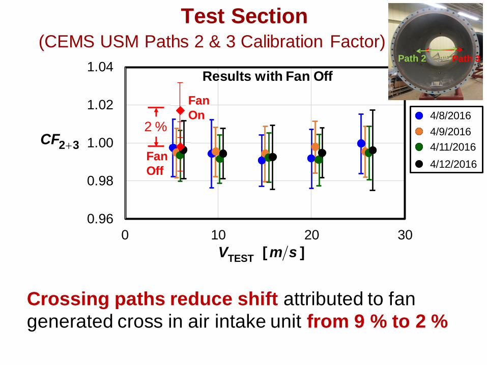
Test Section (CEMS USM Paths 2 & 3 Calibration Factor)
2 3CF
TEST [ ]V m s
Path 3Path 2
Fan
Off
Fan
On 2 %
Results with Fan Off
4/8/2016
4/9/2016
4/11/2016
4/12/2016
Crossing paths reduce shift attributed to fan
generated cross in air intake unit from 9 % to 2 %

Summary of Ultrasonic CEMS Flow Monitor
• Single path CEMS
❖ Absolute errors ranged from 5 % to 17 %
❖ Single path performance depends on installation angle
❖ Subject to load dependent calibration factor (3 %)
❖ Not immune to changes in upstream flow field (changed by
9 % due to fan cross flow)
• X-Pattern CEMS
❖ accuracy of 0.5 % in SMSS facility
❖ Calibration factor independent of load
❖ immune to changes in upstream flow field relative to single
path (changed by 2 % due to fan cross flow)
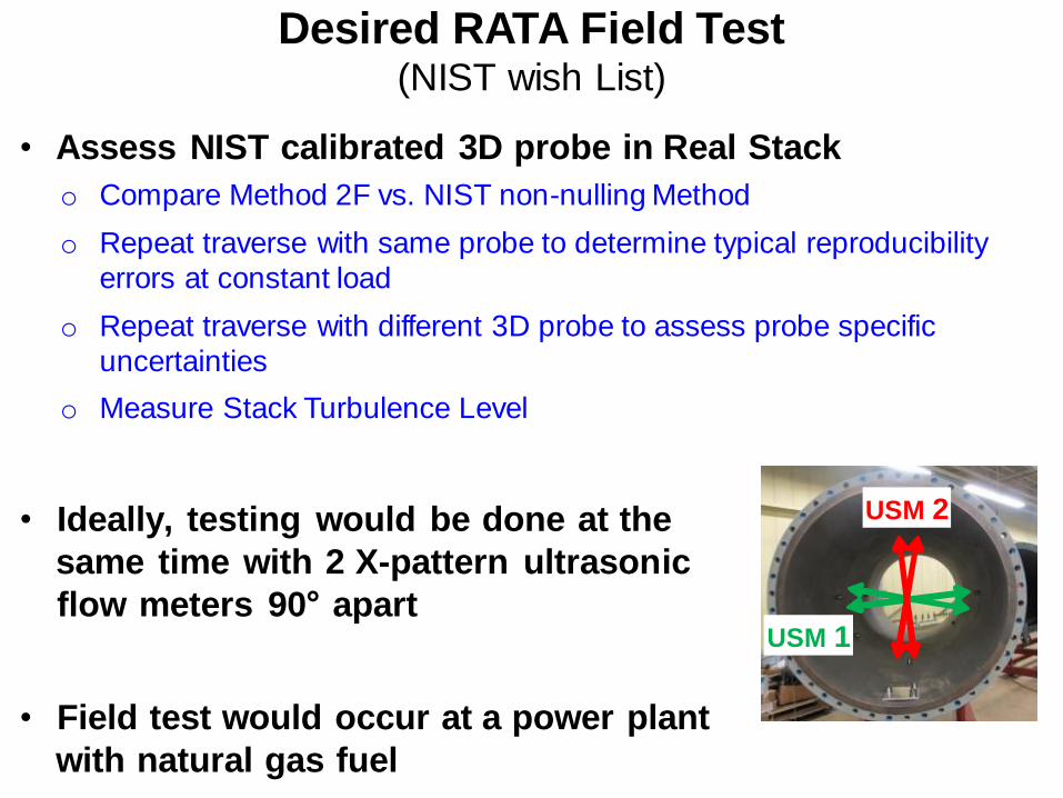
Desired RATA Field Test (NIST wish List)
• Assess NIST calibrated 3D probe in Real Stack
o Compare Method 2F vs. NIST non-nulling Method
o Repeat traverse with same probe to determine typical reproducibility
errors at constant load
o Repeat traverse with different 3D probe to assess probe specific
uncertainties
o Measure Stack Turbulence Level
• Ideally, testing would be done at the
same time with 2 X-pattern ultrasonic
flow meters 90° apart
• Field test would occur at a power plant
with natural gas fuel
USM 1
USM 2

Questions?