NikoN Metrology News
22
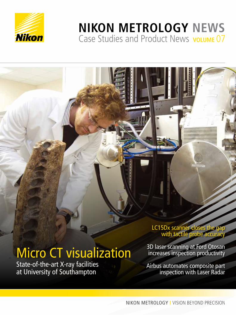
LC15Dx scanner closes the gap with tactile probe accuracy 3D laser scanning at Ford Otosan increases inspection productivity Airbus automates composite part inspection with Laser Radar Micro CT visualization State-of-the-art X-ray facilities at University of Southampton NIKON METROLOGY NEWS Case Studies and Product News VOLUME 07
Transcript of NikoN Metrology News
LC15Dx scanner closes the gapwith tactile probe accuracy
3D laser scanning at Ford Otosan increases inspection productivity
Airbus automates composite part inspection with Laser Radar
Micro CT visualizationState-of-the-art X-ray facilitiesat University of Southampton
NikoN Metrology NewsCase Studies and Product News VoluMe 07
NikoN lC15DxClosiNg the gap
with touCh probe aCCuraCy
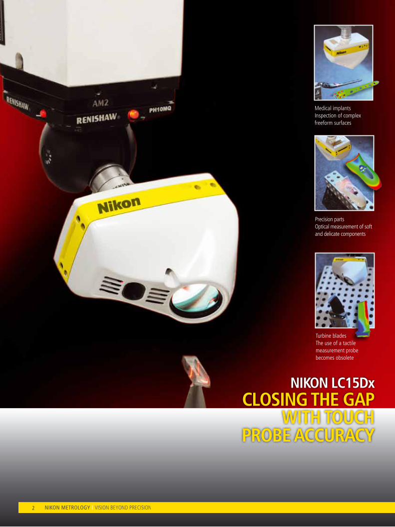
Medical implantsInspection of complex freeform surfaces
Turbine bladesThe use of a tactile measurement probe becomes obsolete
Precision partsOptical measurement of soft and delicate components
2
ContentNikon lC15Dx scanner 4
Airbus automates A340/350/380 composite nose cowl inspection 6
Inaugurated X-ray research facilities at Southampton University 8
New integrated sensor further increases iGPS usability and performance 11
Nikon Metrology iGPS helps lASR lab 12
Ford Otosan standardizes on Nikon Metrology for faster-turnaround vehicle body inspection 14
Focus 10 17
Micro CT providing details and insight unattainable by other means 18
CMM-Manager 3.1 21
Send your feedback and topic suggestions to
+32 (0)16 74 01 00
Nikon Metrology NV
Geldenaaksebaan 329 - 3001 leuven - Belgium
www.nikonmetrology.com
Order your free copy of Nikon Metrology News through
Pict
ure
on c
over
© x
xxxx
xxx
News I Volume 6 3
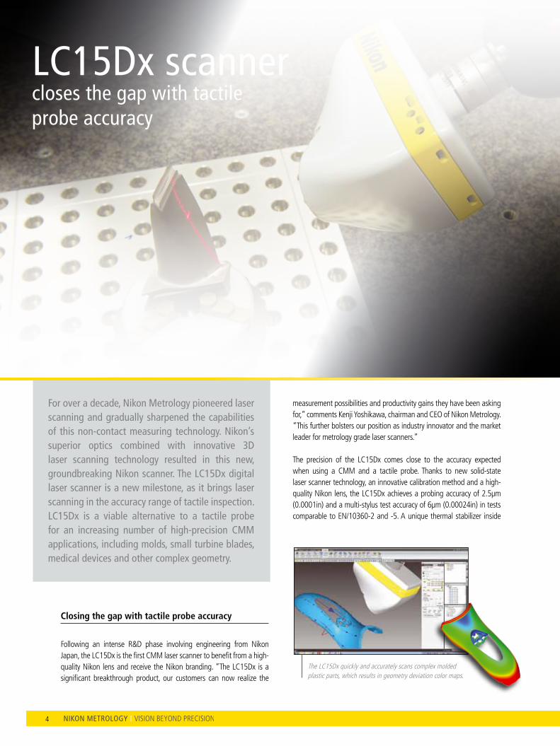
For over a decade, Nikon Metrology pioneered laser scanning and gradually sharpened the capabilities of this non-contact measuring technology. Nikon’s superior optics combined with innovative 3D laser scanning technology resulted in this new, groundbreaking Nikon scanner. The LC15Dx digital laser scanner is a new milestone, as it brings laser scanning in the accuracy range of tactile inspection. LC15Dx is a viable alternative to a tactile probe for an increasing number of high-precision CMM applications, including molds, small turbine blades, medical devices and other complex geometry.
From Metris to Nikon MetrologyNIkON MeTROLOgy I VISION BeyOND PReCISION
measurement possibilities and productivity gains they have been asking for,” comments Kenji yoshikawa, chairman and CeO of Nikon Metrology. “This further bolsters our position as industry innovator and the market leader for metrology grade laser scanners.” The precision of the lC15Dx comes close to the accuracy expected when using a CMM and a tactile probe. Thanks to new solid-state laser scanner technology, an innovative calibration method and a high-quality Nikon lens, the lC15Dx achieves a probing accuracy of 2.5µm (0.0001in) and a multi-stylus test accuracy of 6µm (0.00024in) in tests comparable to eN/10360-2 and -5. A unique thermal stabilizer inside
Closing the gap with tactile probe accuracy
Following an intense R&D phase involving engineering from Nikon Japan, the lC15Dx is the first CMM laser scanner to benefit from a high-quality Nikon lens and receive the Nikon branding. “The lC15Dx is a significant breakthrough product, our customers can now realize the
The lC15Dx quickly and accurately scans complex molded plastic parts, which results in geometry deviation color maps.
LC15Dx scanner closes the gap with tactile probe accuracy
4

News I Volume 7 5
the scanner body eliminates the uncertainty and delay caused when the laser scanner is used before it has reached operating temperature. Probe tip compensation errors are also eliminated by using non-contact triangulation between the laser source, workpiece and CCD sensor to measure the surface of the workpiece directly.
Versatile scanning without the hassle
The lC15Dx provides significant benefits for a wide variety of high-precision parts and geometry, including small details, semi-rigid parts and the more demanding materials. A greater range and mix of surface materials, finishes, colors and transitions can be measured more efficiently without user interaction, manual tuning and part spraying. Nikon Metrology’s unique third-generation enhanced Scanner Performance (eSP3) technology maintains accuracy, speed and data quality by intelligently adapting the laser settings for each measured point in real-time. Unwanted reflections are neutralized by an advanced software filter while changes in ambient light are absorbed by a high-grade daylight filter. better insights, earlier
Manufacturers gain a full appreciation of the dimensional quality of their products without compromising on cycle times. As the lC15Dx passes over the workpiece, a laser line is projected onto the surface. The line measures 70,000 points per second at intervals of 22µm (0.0008in). As the entire part is checked to the design intent CAD model, any areas of concern are immediately highlighted using color mapping. Further investigation and analysis is possible using fly-outs, sections and a library of Geometric Dimensioning and Tolerancing (GD&T). Multi-sensor applications, ready to retrofit to your CMM
In situations where a single sensor technology is insufficient for measuring all the features, the lC15Dx can be combined with a tactile probe and change rack to create a versatile fully automated multi-sensor CMM. Depending on the application both technologies can be used independently or together within the same inspection program.The lC15Dx is available with any Nikon Metrology CMM and can be retrofitted to existing CMMs fitted with CMM controllers from Aberlink, Deva, Coord3, Dukin, lK, Hexagon DeA, Hexagon Brown & Sharpe, Hexagon Sheffield, Mitutoyo, Mora, Renishaw, Wenzel, Werth, Zeiss and probe heads Renishaw PH10M, PH10MQ, PHS and Hexagon CW43.However, unlike a tactile probe, the lC15Dx uses non-contact 3D laser triangulation to measure the surface directly. A unique thermal stabilizer inside the scanner body eliminates the uncertainty and delay caused when the laser scanner is used before it has reached operating temperature. The lC15Dx offers the accuracy, resolution and speed to successfully tackle the more demanding turbine blade metrology applications.
By capturing 70,000 points per second, the lC15Dx achieves high freeform surface scanning resolution.
The most challenging turbine blade inspection tasks can be tackled with the lC15Dx, driving highly accurate part-to-CAD comparison.
5
The lC15Dx scans a complex lower jaw implant incorporating articulated joints and dedicated features.
in a nutshell
Probing error (MPeP) 2.5µm (0.0001in)
Multi-stylus test (MPeAl) 6µm (0.00024in)
Data acquisition (approx.) 70,000 points/sec
Points per line (approx.) 900

6
FMI masters silicone molding of critical medical components using iNexiv
iNexiv adds speed and quality to ultra-clean molding of silicone components that go into lifesaving medical devices
The nacelle inlet cowl is riveted and glued to the main jet engine body in Nantes. “To speed up inspection, Airbus was looking for a metrology system that is accurate and fast enough to measure the large nacelle air inlet assemblies more productively,” explains Thierry Pavageau, responsible for the integration project at Airbus Nantes and currently equipment Maintenance Manager A350 Unit. The assembly of different body components and engine takes place in a dedicated factory wherefrom the complete engines are sent to the final assembly line in Toulouse. The aero engines themselves are manufactured by engine Alliance (CFMI, Pratt&Whitney) or Rolls-Royce, depending on the engine model and type.
Nantes’ leadership in composite part manufacturing
Airbus’ Nantes site in France is a leader in the manufacture of composite structural parts, such as the nacelle air inlet cowls for the engines of A340-500/600, A350 and A380. Composite materials have gained popularity in high-performance structures that need to be lightweight, yet strong enough to take harsh loading conditions. The inner side of a nacelle air inlet is made of nature composite material and the leading edge is made of aluminum. Inlet cowls are designed for low weight and minimum aerodynamic resistance to help increase aircraft mileage.
Airbus automates A340/350/380 composite nose cowl inspection using Nikon Metrology Laser Radar
every micron counts when high in the sky, massive airflows are sucked into the jet engine inlets. The size and sophistication of composite jet engine inlet cowls for Airbus A340/350/380 aircraft call for a dedicated metrology approach. To inspect inlet cowl form and assembly, Airbus opted for a Laser Radar inspection cell that turns around inspection in a fast and automated fashion. Inlet cowl measurements are needed to detect deformations or assembly faults causing aerodynamic disturbances that potentially induce excess vibration or increase fuel consumption. According to Airbus, the Laser Radar illustrates how an integrated metrology solution offers automated targetless inspection and smooth production floor operation.

7News I Volume 7
Metrology search ultimately led to laser radar
The laser Radar measures the freeform internal and external cowl surfaces as well as the precise gap and step between the leading edge and the mentioned surfaces. “We analyze the acquired data to ensure high-quality assembly and part mating. From an efficiency standpoint, it was important for us that the entire process from measurement to final report could be executed automatically with just a single mouse click.”
When looking for a suitable measurement solution, traditional CMMs were eliminated as the inspection of composite materials preferably were measured using a non-contact technique. Also the necessary foundation on the shop floor and part loading system for a gantry CMM suitable for measuring objects of this size is an very costly.
At the time when system was selected, the use of 3D laser trackers was also not an option for an automated application. 3D Trackers required an operator to manually hold a spherically mounted retroreflector (SMR) or a handheld probe. Human interaction slows down the inspection process, and is too error prone to comply with Airbus’ extreme safety precautions. Also photogrammetry was investigated, and although interesting for surface inspection, this measurement technology did not provide an appropriate solution for gap & step measurement. Finally, Airbus opted for the integration of a laser Radar system, which combines automated non-contact laser measurement, surface and feature scanning capability and a dedicated gap&step analysis function.
Completely automated operation
Nikon Metrology teamed with Metrolog and Spatial Analyzer to deliver an automated inspection solution with fast throughput cycles. In the integrated inspection cell in the Airbus assembly hall, the laser Radar system is mounted on a post up in the air, in a fixed tilted position using a custom-designed frame. A technician operates a large gantry crane to correctly position a nose cowl assembly on a large rotating table on the production floor, ready for inspection.
“A single click on a button starts the automatic measurement and analysis procedure,” explains Thierry Pavageau. “The laser Radar instrument references the rotating table by measuring small tooling balls. The Metrolog software controls the rotation increments of the part and the acquisition of laser Radar data. During a single revolution, the laser Radar measures over 1,000 surface points to capture the 3D geometry of the leading edge. The inspection cycle also covers scanning 250 gap and step positions to evaluate part mating between leading edge and inlet body. Other measurements involve the anti-ice interface, which can be accessed by the laser Radar using a mirror.” When directing a focused laser beam to a point, the laser Radar only requires a billionth of the reflected light to exactly measure the absolute range to the point, with 250 micron accuracy over a 25 meter distance.
Pavageau says that all results are instantly processed and summarized in an easy-to-interpret report. “Color-coded areas on part-to-CAD comparison charts graphically illustrate the geometric deviation of the leading edge and other surfaces. The operator verifies out-of-spec tolerances, and in case of anomalies informs the quality department for further investigation.”
laser radar slashes inspection time and operator overhead
Airbus is satisfied that the complete inspection cycle from nose cowl positioning to graphic report is completed in only 90 minutes. “The optimization of the automatic inspection cell saves us two and a half hours inspection time for every A340/350/380 nose cowl assembly that passes through the cell,” concludes Pavageau. “This means a 60% productivity increase in comparison with the old station. Important in streamlining this process was the introduction of the laser Radar instrument and the enhanced calculation algorithm for gap & step measurement. Furthermore, no operator action is required whatsoever because the laser Radar system eliminates the use of photogrammetry targets, retro-reflectors or handheld probes.” The laser Radar inspection cell was originally deployed for inspection of A340 /A380 engines cowls and has recently been approved for inspection of A350 engines.
laser Radar executes automatic freeform surface and gap & step measurements at every increment of the rotating nose cowl.
Airbus opted for an automated laser Radar inspection cell that drastically speeds up nose cowl inspection.
The color-coded areas graphically illustrate the geometric deviation of the leading edge surface.

8
Inaugurated X-ray research facilities at
Southampton University
Nikon Metrology systems support micro visualization in industry and academia
A new groundbreaking research center designed to examine materials and structures across many length scales has been launched at the University of Southampton. The µ-VIS (micro-vis) X-ray Imaging Center examines the internal structure of objects in incredible detail. It produces high-resolution 3D images that support research in fields ranging from biomedical science to engineering, and archaeology to modern environmental science. The new £2.2 million research facilities provide micro-focus computed tomography (CT) imaging to exceptional energy and length scales (up to 450 kV, imaged volumes in excess of 1 cubic meter), whilst offering complementary resolution capabilities down to 200nm.
The center integrates state-of-the-art imaging hardware, world-class computing and image processing expertise to acquire and process the 3D data that is needed to break new ground.
Three systems installed at the state-of-the-art X-ray Imaging Center are from Nikon Metrology, namely a custom-designed Hutch, with a 450 kV and 225 kV source as well as a flat panel and line array detector, a modified XT H 225 ST cabinet system and a 160kV Xi Benchtop scanner. The Centre additionally incorporates a Gatan XuM/Zeiss evo MA25 nanoCT system and a SkyScan1176 for in vivo CT (small animal studies). The µ-VIS scanners work in much the same way as a medical CT scanner, but at higher resolutions, by taking thousands of X-ray views to build up a 3D image of the examined object. Beautifully rendered CT images illustrate its capability in measuring internal and external dimensions and the critical insight it provides through the additional fourth dimension of material density. looking inside objects at this level of detail in a non-destructive way is a huge advantage when studying objects that either cannot be dismantled or are too unique, delicate or complicated to take apart.
looking inside objects at very detailed levels
Inaugurated on September 16th, 2011, Southampton’s µ-VIS Imaging Center is equipped to achieve breakthroughs in the engineering, biomedical, environmental and archaeological sciences.

9News I Volume 7
a ferocious predator’s jaw
The opening seminar at the Center’s inauguration event was organized as a symposium focusing on application results. Professor Ian Sinclair, the Head of the µ-VIS Center, discussed the Weymouth Pliosaur research where a 2.5-meter long jaw has been scanned and reconstructed using the custom Hutch system, as widely reported on the BBC last December. 3D rendering and CT image slice of a Pliosaur jaw, reconstructed using scans taken in the Nikon Metrology bay.
The huge Nikon Metrology X-ray bay is ideal for scanning such large, dense lumps of fossil. The X-rays are helping to build up a 3D picture of this ferocious predator, which terrorized the oceans 150 million years ago. It concerns an aquatic reptile with a huge bulky body, paddle-like limbs and an enormous crocodile-like head packed full of razor-sharp teeth. By looking at the inner architecture of the skull, scientists may gain new insights into the species and its evolution.Other natural specimen studies include the scanning of large numbers of mice as models for numerous human conditions, including osteoporosis. Researchers have for example recently used the XT H 225 ST equipped with a transmission target to scan the bones of gene knock-out mice elucidating for the first time the critical role of certain proteins in bone fragility. The pore analysis method applied illustrates how much insight could be gained through creative X-ray image and CT slice post-processing.
Important issues for future farming were investigated via quantification of the structure of soils and development of living plant roots, supporting multi-physics modelling of how this may affect both irrigation and phosphate utilisation.
“ The huge Nikon Metrology X-ray bay is ideal for scanning such large, dense lumps of fossil.
3D rendering of an aircraft wing part (~400mm across) scanned using a 450kV X-ray source and a curved linear detector array.
Complementary microfocus and synchrotron CT imaging of murine bone geometry and ultrastructure (P. J. Thurner et al., Bone, 46(2010), pp. 1564-1573 doi:10.1016/j.bone.2010.02.01)

10
3D rendering of an aircraft wing part (~400mm across) scanned using a 450kV X-ray source and a curved linear detector array.
The impressive XT H 450 system offers several microfocus X-ray source options along with flat panel and linear array detectors.
Fatigue damage in high strength Al-alloys, as used in high pressure gas containment systems.
3D CT rendering clearly illustrates the fibre orientation and damage that are observed in laminates.
X-ray makes the difference in engineering insight
Industrial engineering benefits greatly from the broad application reach of CT scanning. Groundbreaking research involved the study of carbon fiber/epoxy used to coat aluminum gas bottles to reduce weight. The research looked into the resistance to damage using all scales of the µ-VIS Imaging activities. The full engineering components were initially scanned in their intact form, with subsequent targeted higher resolution sub-sampling elucidating structures at individual ply, tow and, ultimately, discrete carbon fibre levels. This work has allowed established theories of fibre failure modes to be explicitly compared with experimental results for the first time at both coupon and engineering component levels.
A railway engineering study reported on the effect of long term use of the ballast underneath railway sleepers (railroad ties). The crushed-stone ballast facilitates drainage of water and distributes the load from the railway sleepers. Taking several scans of such a dense material at meaningful sample length scales (sample in the order of 300-400mm diameter) confirmed that critical data on individual particle rotations could be obtained in acceptable time scales using the custom hutch’s curved linear array and 450kV source. The results are now being taken forward to validate DeM (discrete element method) simulations of ballast deformation.
More information can be found at http://www.soton.ac.uk/muvis/

11News I Volume 5
5.3x 16.7x
New integrated sensor further
increases igPS usability and performance
iGPS is a metrology system that uses a network of laser transmitters to create a measurement volume that can range in size from small vehicle assembly shops up to large aircraft final assembly lines. The i5is sensor is a major leap forward in both performance & measurement reliability. It integrates three previously separate components into one device while significantly improving data quality, extending measurement range, and improving accuracy.
higher accuracy over an extended range
New electronics ensure that the i5is is virtually unaffected by optical and environmental noise caused by lighting conditions & eMI sources. This reduces systematic biases more than 50%, driving down iGPS measurement uncertainty and improving effective transmitter-to-sensor range.
reliable, compact and easy to use
With wired and wireless communication, support for three different power options, and a configurable sleep mode, the i5is can be used in almost any situation. To add a new i5is into an iGPS network, simply turn it on and the software will automatically recognize and configure it for use.
enhances the strengths of igps
Typical assembly/alignment assistance and dynamic tracking applications include aerospace part/jig alignment, aircraft final assembly, robotic vehicle tracking and machine guidance. i5is sensors can be quickly and easily deployed to track an object’s native coordinate system in 6 degrees of freedom, or provide relative positional feedback of multiple objects.
The i5 Integrated Sensor (i5is) is a new fully integrated 5 degree of freedom measurement device for applications ranging from vehicle tracking to automated assembly of large parts.
The i5is handheld sensor increases performance and measurement reliability in a variety of assembly/alignment assistance and dynamic tracking applications.
12
Nikon Metrology igPS helps LASR Lab research advanced trajectory following
for space applications
hoMer proximity operation experiments at lasr
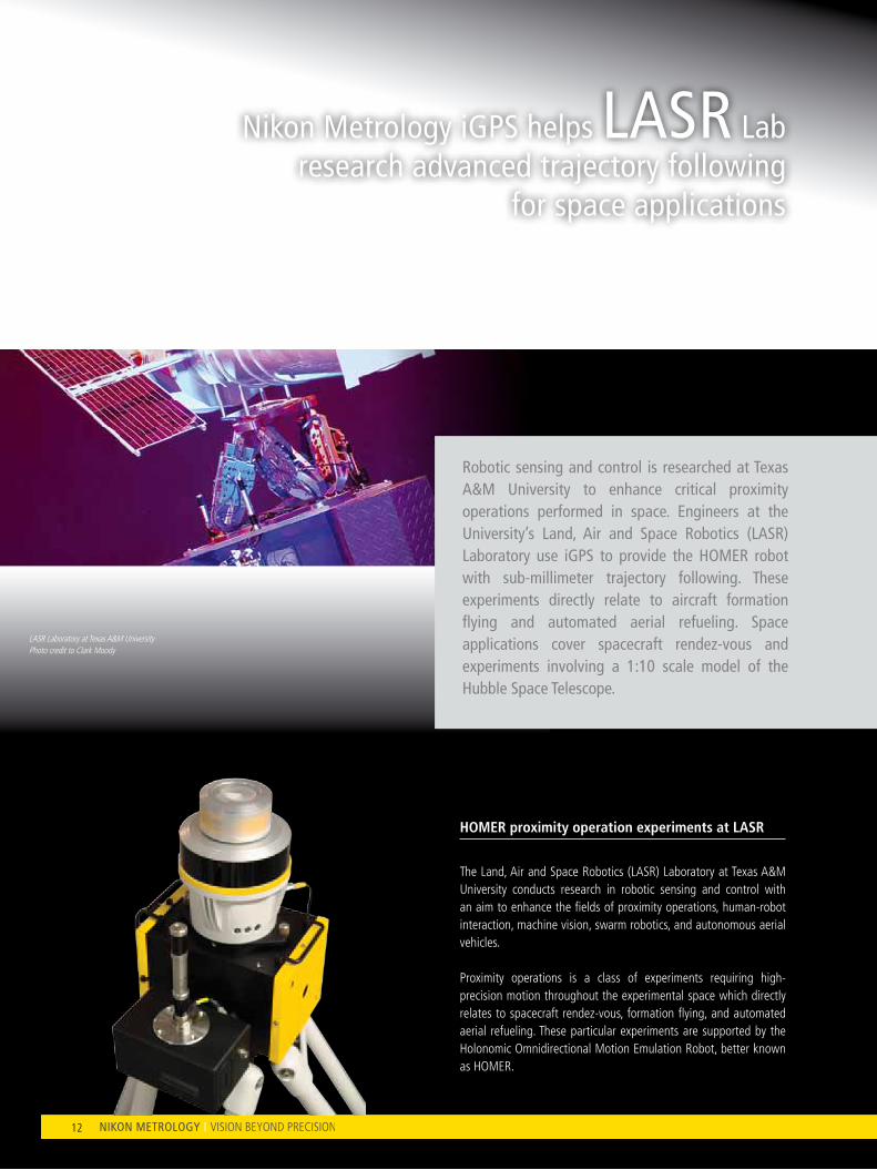
The land, Air and Space Robotics (lASR) laboratory at Texas A&M University conducts research in robotic sensing and control with an aim to enhance the fields of proximity operations, human-robot interaction, machine vision, swarm robotics, and autonomous aerial vehicles.
Proximity operations is a class of experiments requiring high-precision motion throughout the experimental space which directly relates to spacecraft rendez-vous, formation flying, and automated aerial refueling. These particular experiments are supported by the Holonomic Omnidirectional Motion emulation Robot, better known as HOMeR.
lASR laboratory at Texas A&M University Photo credit to Clark Moody
Robotic sensing and control is researched at Texas A&M University to enhance critical proximity operations performed in space. engineers at the University’s Land, Air and Space Robotics (LASR) Laboratory use igPS to provide the HOMeR robot with sub-millimeter trajectory following. These experiments directly relate to aircraft formation flying and automated aerial refueling. Space applications cover spacecraft rendez-vous and experiments involving a 1:10 scale model of the Hubble Space Telescope.
13News I Volume 7 13News I Volume 6
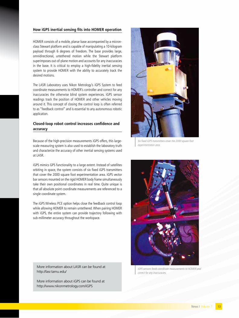
how igps inertial sensing fits into hoMer operation
HOMeR consists of a mobile, planar base accompanied by a micron-class Stewart platform and is capable of manipulating a 10-kilogram payload through 6 degrees of freedom. The base provides large, omnidirectional, untethered motion while the Stewart platform superimposes out-of-plane motion and accounts for any inaccuracies in the base. It is critical to employ a high-fidelity inertial sensing system to provide HOMeR with the ability to accurately track the desired motions.
The lASR laboratory uses Nikon Metrology’s iGPS System to feed coordinate measurements to HOMeR’s controller and correct for any inaccuracies the otherwise blind system experiences. iGPS sensor readings track the position of HOMeR and other vehicles moving around it. This concept of closing the control loop is often referred to as “feedback control” and is essential to any autonomous robotic application. Closed-loop robot control increases confidence and accuracy
Because of the high-precision measurements iGPS offers, this large-scale measuring system is also used to establish the laboratory truth and characterize the accuracy of other inertial sensing systems used at lASR. iGPS mimics GPS functionality to a large extent. Instead of satellites orbiting in space, the system consists of six fixed iGPS transmitters that cover the 2000 square foot experimentation area. iGPS vector bar sensors mounted on the rigid HOMeR body frame simultaneously take their own positional coordinates in real time. Quite unique is that all absolute point coordinate measurements are referenced to a single coordinate system.
The iGPS Wireless PCe option helps close the feedback control loop while allowing HOMeR to remain untethered. When pairing HOMeR with iGPS, the entire system can provide trajectory following with sub-millimeter accuracy throughout the workspace.
Six fixed iGPS transmitters cover the 2000 square foot experimentation area.
iGPS sensors feeds coordinate measurements to HOMeR and correct for any inaccuracies.
More information about LASR can be found at http://lasr.tamu.edu/
More information about iGPS can be found at http://www.nikonmetrology.com/iGPS
News I Volume 7
14
technology-driven commercial vehicle manufacturing
Ford Otosan’s success story started in 1961, when Ford Motor Company and Koç Holding established the company in Turkey. Half a century later, Ford Otosan is the undisputed leader in the fast-growing Turkish automotive industry. In 2010, the company extended total manufacturing capacity to 330.000 units.
“In 2004 the Kocaeli plant became Transit’s main worldwide production center, owing to the production quality of Turkish workers and state-of-the-art manufacturing technology,” says Murat Öztürk, Dimensional Control Team leader at the Ford Otosan commercial vehicle plant in Kocaeli, Turkey. “3D laser scanning is an example of an enabling inspection technology currently being deployed more widely at Ford Otosan. We are long-time users of the lC50 laser scanner for a variety of inspection applications. Today we use an XC65D Cross Scanner to inspect full-vehicle body structures of the Transit Connect, and decided to purchase an additional Nikon Metrology scanner.”
The XC65D is a “3-in-1” scanner incorporating 3 laser/camera sets mounted in a cross pattern. Nikon Metrology pioneered multi-sensor scanner technology because it allows geometric features to be captured from different sides simultaneously. This is how the Cross Scanner accurately digitizes the complete shape of slots, sleeves, holes and other feature types in a single scan. The scanner is equally suitable for digitizing freeform surfaces and edges.
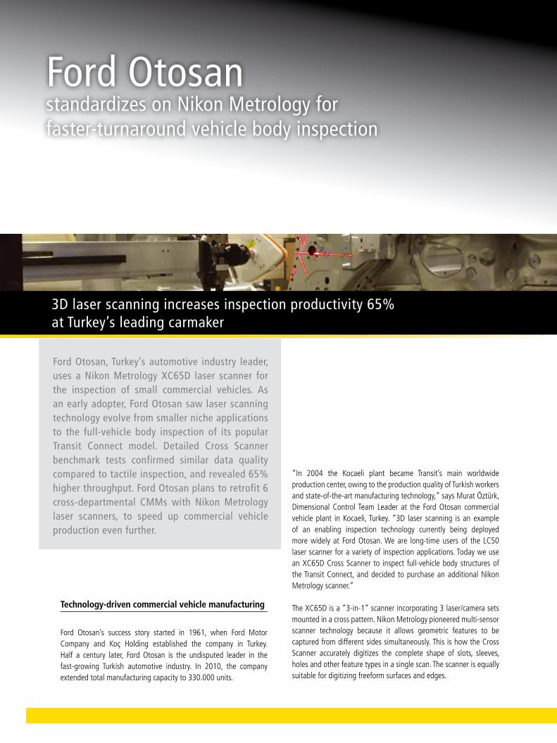
Ford Otosan, Turkey’s automotive industry leader, uses a Nikon Metrology XC65D laser scanner for the inspection of small commercial vehicles. As an early adopter, Ford Otosan saw laser scanning technology evolve from smaller niche applications to the full-vehicle body inspection of its popular Transit Connect model. Detailed Cross Scanner benchmark tests confirmed similar data quality compared to tactile inspection, and revealed 65% higher throughput. Ford Otosan plans to retrofit 6 cross-departmental CMMs with Nikon Metrology laser scanners, to speed up commercial vehicle production even further.
3D laser scanning increases inspection productivity 65% at Turkey’s leading carmaker
Ford Otosan standardizes on Nikon Metrology for faster-turnaround vehicle body inspection
15News I Volume 7
laser scanning versus tactile inspection
The purchase resulted from a detailed comparative study involving both laser scanning and touch probe measurement. Murat Öztürk explained that the study entailed the serial inspection of a number of Connect vehicle bodies. One CMM captured the right half of the body using the XC65D laser scanner, while the other took touch probe measurements on the left half of the body. The tactile inspection CMM was equipped with a TP20 probe mounted on a PH10M indexing head. Both automated inspection methods were set up to measure exactly the same features, pillars, panels, etc. in a mirrored layout.
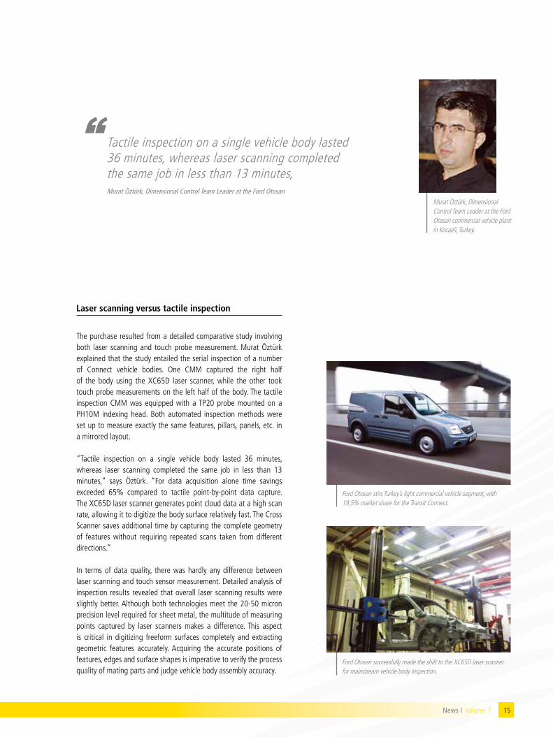
“Tactile inspection on a single vehicle body lasted 36 minutes, whereas laser scanning completed the same job in less than 13 minutes,” says Öztürk. “For data acquisition alone time savings exceeded 65% compared to tactile point-by-point data capture. The XC65D laser scanner generates point cloud data at a high scan rate, allowing it to digitize the body surface relatively fast. The Cross Scanner saves additional time by capturing the complete geometry of features without requiring repeated scans taken from different directions.” In terms of data quality, there was hardly any difference between laser scanning and touch sensor measurement. Detailed analysis of inspection results revealed that overall laser scanning results were slightly better. Although both technologies meet the 20-50 micron precision level required for sheet metal, the multitude of measuring points captured by laser scanners makes a difference. This aspect is critical in digitizing freeform surfaces completely and extracting geometric features accurately. Acquiring the accurate positions of features, edges and surface shapes is imperative to verify the process quality of mating parts and judge vehicle body assembly accuracy.
Ford Otosan stirs Turkey’s light commercial vehicle segment, with 19,5% market share for the Transit Connect.
Ford Otosan successfully made the shift to the XC65D laser scanner for mainstream vehicle body inspection.
Murat Öztürk, Dimensional Control Team leader at the Ford Otosan commercial vehicle plant in Kocaeli, Turkey.
“ Tactile inspection on a single vehicle body lasted 36 minutes, whereas laser scanning completed the same job in less than 13 minutes,Murat Öztürk, Dimensional Control Team Leader at the Ford Otosan

Faster inspection – better insight – higher quality
According to Öztürk, laser scanning simplified the entire vehicle body inspection process. “Defining the straightforward scanner travel paths is easier for us than specifying individual touch probe points. After acquiring the data, the Nikon Metrology Focus software automatically filters the resulting point cloud and fits a 3D surface through the points. Focus processes the scan data for numerical analysis as well as graphic comparison against nominal CAD. Color-coded visual inspection reports help us understand the source of the slightest deviation in feature positioning or surface geometry. This information provides the insight we need to take appropriate preventive measures in the vehicle body assembly line.” “Non-contact vehicle body measurement speeds up every step in the process, and delivers more profound insight to take better-informed manufacturing decisions,” concludes Öztürk. “With our latest scanner purchase, we will have a dual-arm CMM fully operational with laser scanning and Focus point cloud processing software. Also during new model vehicle launch projects, we use laser scanning to digitize complete individual parts for analysis purposes. In this regard, detailed scan reports are very useful for in-depth evaluations run in our own department as well as collaborative work done with other departments. For the future, we consider having 6 CMMs in different departments equipped with laser scanners from Nikon Metrology. This complies with Ford Otosan’s strategy to strengthen our competitive edge through technologies that increase product quality and process efficiency.”
Graphic comparison against nominal CAD steers preventive measures in the vehicle body assembly line.
laser scanners acquire point clouds that support accurate geometric feature extraction from the cloud.
The Nikon Metrology XC65D laser scanner captures geometric features from 3 sides simultaneously.
More information about Ford Otosan can be found at http://www.fordotosan.com.tr/en/default.htm
More information about Laser Scanners can be found at http://www.nikonmetrology.com/cmm_scanners/
16
17News I Volume 7 17News I Volume 6
Focus’ rich functionality for part-to-CAD or feature inspection is available for processing point clouds originating from manual or CMM measurements.
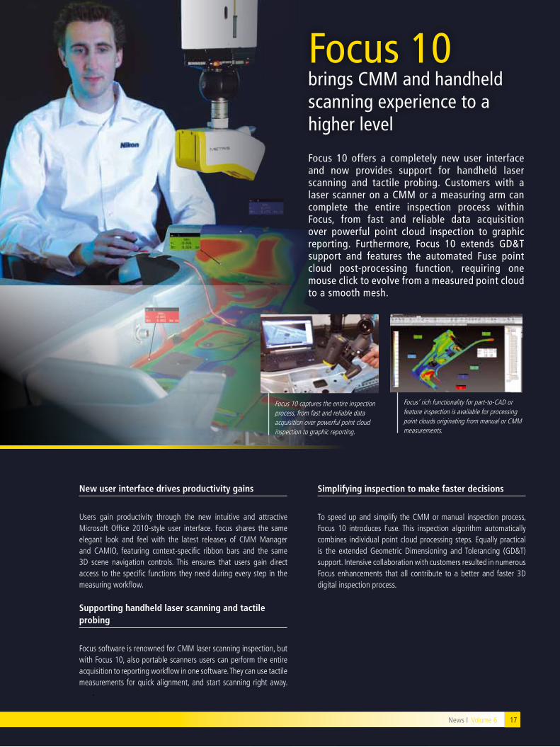
Focus 10 offers a completely new user interface and now provides support for handheld laser scanning and tactile probing. Customers with a laser scanner on a CMM or a measuring arm can complete the entire inspection process within Focus, from fast and reliable data acquisition over powerful point cloud inspection to graphic reporting. Furthermore, Focus 10 extends gD&T support and features the automated Fuse point cloud post-processing function, requiring one mouse click to evolve from a measured point cloud to a smooth mesh.
New user interface drives productivity gains
Users gain productivity through the new intuitive and attractive Microsoft Office 2010-style user interface. Focus shares the same elegant look and feel with the latest releases of CMM Manager and CAMIO, featuring context-specific ribbon bars and the same 3D scene navigation controls. This ensures that users gain direct access to the specific functions they need during every step in the measuring workflow.
supporting handheld laser scanning and tactile probing
Focus software is renowned for CMM laser scanning inspection, but with Focus 10, also portable scanners users can perform the entire acquisition to reporting workflow in one software. They can use tactile measurements for quick alignment, and start scanning right away.
simplifying inspection to make faster decisions
To speed up and simplify the CMM or manual inspection process, Focus 10 introduces Fuse. This inspection algorithm automatically combines individual point cloud processing steps. equally practical is the extended Geometric Dimensioning and Tolerancing (GD&T) support. Intensive collaboration with customers resulted in numerous Focus enhancements that all contribute to a better and faster 3D digital inspection process.
Focus 10 brings CMM and handheld scanning experience to a higher level
Focus 10 captures the entire inspection process, from fast and reliable data acquisition over powerful point cloud inspection to graphic reporting.
(A) 3D CT slice showing the fusee click teeth of a 300 year old pocket-watch. (©Trustees of NMS)
Micro CT providing details and insight unattainable by other means
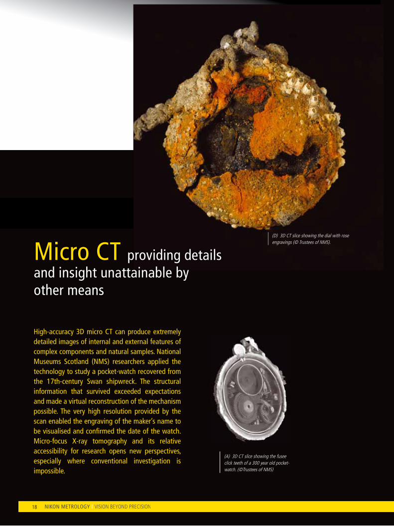
High-accuracy 3D micro CT can produce extremely detailed images of internal and external features of complex components and natural samples. National Museums Scotland (NMS) researchers applied the technology to study a pocket-watch recovered from the 17th-century Swan shipwreck. The structural information that survived exceeded expectations and made a virtual reconstruction of the mechanism possible. The very high resolution provided by the scan enabled the engraving of the maker’s name to be visualised and confirmed the date of the watch. Micro-focus X-ray tomography and its relative accessibility for research opens new perspectives, especially where conventional investigation is impossible.
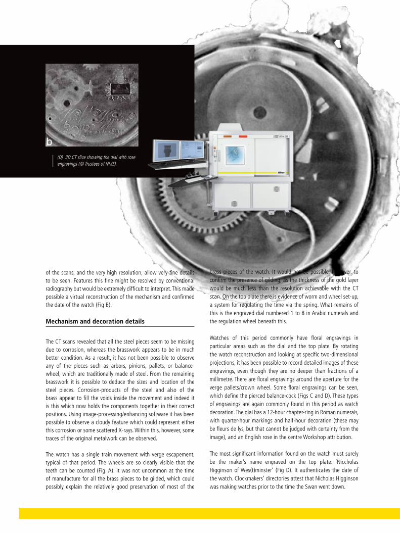
(D) 3D CT slice showing the dial with rose engravings (© Trustees of NMS).
18

19News I Volume 7
the stand for investigation. The main limitation of such analysis is generally the maximum depth to which X-rays will penetrate. This depends on the X-ray energy used and the material density - for brass at 225 kV the maximum depth will be typically c.40 mm—and also the limited space in the CT system, suitable only for small, relatively light objects. These conditions will limit the investigation of dense materials like heavy metals. The mounting requires the object to be centred and completely stable during the scanning to allow accurate registration of the position of each X-ray image. The manipulator is accurate to about 2 mm and rotates with a precision of less than 70 milli-radians.
The object was investigated using an XT H 225 system from Nikon Metrology, using a 5 μm spot size 225 kV tube with an amorphous silicon flat-panel detector. The resolution obtained on the CT scan is 63 μm, that is a voxel size of 63 μm. The data were then reconstructed using Nikon Metrology’s CT-Pro Computed Tomography software and visualised using VolumeGraphics software. An Audio Video Interleave animation (AVI) showing a three-dimensional reconstruction of the watch and allowing one to pass through the sample from the outside to the inside has been produced. This movie can be seen on the NMS website (http://www.nms.ac.uk/highlights/objects_in_focus/swan_pocket_watch.aspx).
There was some assumption of interesting results following the two-dimensional radiograph: however, the condition of surviving interior pieces exceeded our expectation. The 3-dimensional nature
a rusty watch relic
The study of the pocket-watch from the Swan illustrates the great potential of 3D Computed Tomography scanning for the study of archaeological objects. In 1994 the wreck of a small 17th-century warship, believed to be the Swan, was found off Duart Castle in the Sound of Mull, off the west coast of Scotland. The Swan was identified by several of its features, including a pocket-watch. It is relatively rare to find a watch from this period, let alone one that has been under the sea for 350 years.
X-ray radiography of the watch was undertaken in National Museums Scotland (NMS) and revealed that within the lump of concretion some parts of the mechanism have been preserved. Surprisingly, considering the external appearance of the watch, the radiograph indicated the survival of much of the internal mechanism such as the wheels, spring barrel and pillars. However, conventional X-radiography was very limited in its ability to investigate such a small and complicated artifact. At this point conservation work could do little to reveal the mechanism further without irreversibly changing the object.
The Computed Tomography (CT) dataset created along with the image management software, allow the user to visualize the object in three dimensions, to strip away components, and slice it in any arbitrary direction to see interior detail. The watch was mounted in a polythene box, held securely with Plastazote foam, and fixed on
(B) 3D CT images illustrating the reconstruction of the volume of the pocket-watch and its inner mechanism. (© Trustees of NMS)
(C) 3D CT slice showing the engraving on balance back cock. (© Trustees of NMS)
News I Volume 7
20
brass pieces of the watch. It would not be possible, however, to confirm the presence of gilding, as the thickness of the gold layer would be much less than the resolution achievable with the CT scan. On the top plate there is evidence of worm and wheel set-up, a system for regulating the time via the spring. What remains of this is the engraved dial numbered 1 to 8 in Arabic numerals and the regulation wheel beneath this.
Watches of this period commonly have floral engravings in particular areas such as the dial and the top plate. By rotating the watch reconstruction and looking at specific two-dimensional projections, it has been possible to record detailed images of these engravings, even though they are no deeper than fractions of a millimetre. There are floral engravings around the aperture for the verge pallets/crown wheel. Some floral engravings can be seen, which define the pierced balance-cock (Figs C and D). These types of engravings are again commonly found in this period as watch decoration. The dial has a 12-hour chapter-ring in Roman numerals, with quarter-hour markings and half-hour decoration (these may be fleurs de lys, but that cannot be judged with certainty from the image), and an english rose in the centre Workshop attribution.
The most significant information found on the watch must surely be the maker’s name engraved on the top plate: ‘Niccholas Higginson of Wes(t)minster’ (Fig D). It authenticates the date of the watch. Clockmakers’ directories attest that Nicholas Higginson was making watches prior to the time the Swan went down.
20
of the scans, and the very high resolution, allow very fine details to be seen. Features this fine might be resolved by conventional radiography but would be extremely difficult to interpret. This made possible a virtual reconstruction of the mechanism and confirmed the date of the watch (Fig B).
Mechanism and decoration details
The CT scans revealed that all the steel pieces seem to be missing due to corrosion, whereas the brasswork appears to be in much better condition. As a result, it has not been possible to observe any of the pieces such as arbors, pinions, pallets, or balance-wheel, which are traditionally made of steel. From the remaining brasswork it is possible to deduce the sizes and location of the steel pieces. Corrosion-products of the steel and also of the brass appear to fill the voids inside the movement and indeed it is this which now holds the components together in their correct positions. Using image-processing/enhancing software it has been possible to observe a cloudy feature which could represent either this corrosion or some scattered X-rays. Within this, however, some traces of the original metalwork can be observed.
The watch has a single train movement with verge escapement, typical of that period. The wheels are so clearly visible that the teeth can be counted (Fig. A). It was not uncommon at the time of manufacture for all the brass pieces to be gilded, which could possibly explain the relatively good preservation of most of the
(D) 3D CT slice showing the dial with rose engravings (© Trustees of NMS).

21News I Volume 7News I Volume 6
CMM-Manager 3.1 further reduces inspection turnaround time
CaD import/export enhancements
Advancements in CAD import and export include improved IGeS import. .STeP and .VDA are additional standard options. Measured clouds now export as a 2D .DFX curve, and support for spatial direct CAD import.
Faster program execution
PH20 advancements include faster program execution and machine movement thanks to block mode execution, a fly mode for blending 3D probe paths. Improved synchronization with UCC server and auto path planning reduce unnecessary clearance moves and dedicated PH20 user settings/preferences. I++ interface enhancements add full support for PH10 probe system and thermal compensation, and multiple default probe assemblies.
extended CMM support
The supported CMM machine controllers now also include Zeiss C98, Deva 4-axis CMM Controller, and Insight Metrology USB Manual Interface. Others are available as well, contact Nikon Metrology for a complete list.
Nikon Metrology integration
CMM-Manager 3.1 features updated and additional integration with Nikon Metrology. It achieves this through a seamless CMM-Manager Feature Tab in Focus Handheld software, added unified configuration for all current Nikon Metrology software, legacy Camio and Focus configurations, and through numerous user interface and settings enhancements.
New capabilities added to the value-for-money tactile inspection software allow users to get even more work done. enhancements related to CAD import/export, PH20 probe head and I++ interface streamline the inspection process further. The software offers extended CMM support, now including compatibility with Nikon, Zeiss, Deva and Insight controllers.
CMM-Manager automatically converts an icon-based inspection routine into a collision-free touch path, delivering graphic part-to-CAD comparison.

NikoN Metrology NVGeldenaaksebaan 329B-3001 leuven, Belgiumphone: +32 16 74 01 00 fax: +32 16 74 01 [email protected]
More offices and resellers at www.nikonmetrology.com
NikoN CorporatioNShin-yurakucho Bldg., 12-1, yurakucho 1-chomeChiyoda-ku, Tokyo 100-8331 Japanphone: +81 3 3773 9026 fax: +81 3 3773 9062www.nikon-instruments.jp/eng/
NikoN Metrology europe NVtel. +32 16 74 01 [email protected]
NikoN Metrology gMbhtel. +49 6023 [email protected]
NikoN Metrology sarltel. +33 1 60 86 09 [email protected]
NikoN Metrology iNC.tel. +1 810 2204360sales_us@nikonmetrology.comus.nikonmetrology.comwww.nikoninstruments.com
NikoN Metrology uk ltD.tel. +44 1332 [email protected]
NikoN iNstruMeNts (shaNghai) Co. ltD.tel. +86 21 5836 0050tel. +86 10 5869 2255 (Beijing office)tel. +86 20 3882 0550 (guangzhou office)
NikoN siNgapore pte. ltD.tel. +65 6559 3618
NikoN Malaysia sDN. bhD.tel. +60 3 7809 3609
NikoN iNstruMeNts korea Co. ltD.tel. +82 2 2186 8400
New
s_Vo
lum
e7_e
N_0
512–
Cop
yrig
ht N
ikon
Met
rolo
gy N
V 20
11. A
ll rig
hts
rese
rved
. The
mat
eria
ls pr
esen
ted
here
are
sum
mar
y in
nat
ure,
sub
ject
to c
hang
e an
d in
tend
ed fo
r gen
eral
info
rmat
ion
only.