NII SHONAN MEETING 048 Industrial Session INTEGRATION …...Contract Based Design •Given an...
51
NII SHONAN MEETING 048 – Industrial Session INTEGRATION OF FORMAL METHODS AND TESTING FOR MODEL BASED SYSTEM-ENGINEERING some thoughts Werner Damm
Transcript of NII SHONAN MEETING 048 Industrial Session INTEGRATION …...Contract Based Design •Given an...

NII SHONAN MEETING 048 – Industrial Session INTEGRATION OF FORMAL METHODS AND TESTING FOR MODEL BASED SYSTEM-ENGINEERING some thoughts Werner Damm

Structure of Presentation
• Objectives and Success Criteria Shonan Meeting
• Example Gaps
• On the Value of Contracts

Objective of meeting
• This meeting aims to provide a forum for researchers and practitioners working on Formal Methods (FM) and Testing to identify research issues toward bringing related ideas, techniques, theories and tools in both research areas to real industrial solutions.

Success Criteria
1. Gap analysis
We have identified
– the major obstacles in industrial deployment of existing formal methods and testing and
– major gaps potentially seen by industry demanding new formal methods and tests for covering these

Success Criteria
2. Technology Push analysis
We have identified the major new technology break-throughs in academic research in the areas of formal methods and testing

Success Criteria
3. Roadmap
We have developed a technology roadmap, which identifies key technologies for resolving obstacles in industrial deployment key technology evolutions from break-thru results to close gaps and characterized their realizability as short term, medium term, long term

GAP ANALYSIS
TEASER –
see separate presentation of gaps identified in meeting

Structure of presentation
• The following information is based on numerous discussion with automotive OEM/suppliers e.g. in my role as Chairman of SafeTRANS (www.safetrans-de.org)
• Focus on three gaps
– coping with complex environments
– coping with complex systems
– coping with disruptive technology changes

Coping with complex environments • overarching challenge: assuring sufficient
levels of consistency between
– world model: what the car believes to be true about its environment (surrounding traffic: position, speed, intention, …., road: road surface, lanes, … )
– and the real world
• NOTE: both directions critical:
– not in real world ⊨ not in world model
– in real world ⊨ in world model

10 Copyright Prevent Project
Understanding the world in which we act

what aspects of the real world
are essential?

The discrepancy between the real world and what
the aircraft perceives as real decide over life and
death
14.09.1993 -
Aircraft thought it was
still airborne, because
only two tons weight
lasted on the wheels
due to a strong side
wind and the landing
maneuver. The computer
did not allow braking.
The plane ran over the
runway into a rampart.


why traditional testing fails
• classical approaches with verification using test vehicles do not scale to this level of complexity, are no longer cost effective (would require 100 Million km test driving)

can the driver take over?
• conditional automation (SAE terminology)
• how can we test whether the driver is able to take over within 10 secs?
• given that sufficient coverage by vehicle testing is commercially not viable

COPING WITH COMPLEX SYSTEMS

17
Copyright Prevent Project
Complex Systems
Source: Aramis Project


Challenge I
Heterogeneity and plurality of test objectives
– hundreds of classes of different test objectives
– Each class addresses specific business needs, such as reliability, availability, safety, robustness, maintainability, costs, etc,
– Each class requires specific methods to guide the transition from (typically informal) requirements to test cases executable on test platforms

Challenge II
• Pushing the technology frontier for test-automation and analysis methods – Expressivity:
• covering all classes of mathematic models required to cover all test-objectives (probabilistic, timed, hybrid systems)
• covering all forms of representations of test models – E.g. Matlab/Simulink Stateflow/Scade/UML, C-code, ....
– Scalability • To complexity of industrial applications
– Quality • Reduction in indeterminate values for static analysis • High model coverage for automatic test generation

COPING WITH DISRUPTIVE TECHNOLOGIES

Examples
1. from 1 function = 1 ECU to Autosar based implementations
a) one ECU hosts several functions
b) one function distributed over several ECUs
2. from single core to multi core processors
3. from 2d transistor realization to 3d transistor realization
4. massive cross-platform re-use
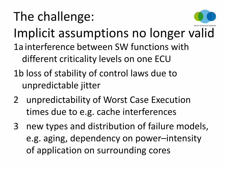
The challenge: Implicit assumptions no longer valid 1a interference between SW functions with
different criticality levels on one ECU
1b loss of stability of control laws due to unpredictable jitter
2 unpredictability of Worst Case Execution times due to e.g. cache interferences
3 new types and distribution of failure models, e.g. aging, dependency on power–intensity of application on surrounding cores

The problem
• record number of recalls
– e.g. in US alone 40 mill vehicles in 2013
• “Warranty Week” estimates costs for recalls to reach 40,000 Million US $ in 2013

The need
• how can we mature processes such that implicit assumptions become explicit?
• how can we assure that a particular integration context meets such assumptions?

CONTRACT BASED SYSTEM ENGINEERING

The key approach
• Explicating all assumptions on the operational context of all critical design artefacts (from complete automotive functions to re-usable SW components)
• For both functional and extra functional characteristics (such as safety, timeliness, resource demands, power, cost, weight)

Contract Based Design
• Given an objective specification of the system
– what the system is supposed to do
– as well as non-functional characteristics (e.g. fault containment, response time, availability, …)
– informal, semi-formal, formal
• under which assumptions on the environment will the system be able to meet its objectives?
• contract: pair of assumptions, objective spec

A simple Example: Objectives
1. top priority: maintain stability of the car
2a. keep car on lane
2b. approximately achieve driver selected speed
3a. follow center of lane
3b. follow driver selected speed almost exactly

Build system re-using previously developed subsystems

Example: Assumptions
• assumptions of the combined ACC-SC relate to the interaction with the driver in choosing a desired speed, and to the evolution of the street
– e.g. curvature of the next road segment is compliant with regulations for curvature on highways
• assumptions of the ACC controller additionally relate to uncontrolled plant actuators, such as the actuators of the lanekeeping controller, SC
– e.g. no uncomissioned lateral acceleration

Strong and weak assumptions
• Strong assumptions characterize
allowed design context
– If component´s environment does not meet
strong assumption, product liability does
not apply
• Weak assumption define a part of the
allowed design context
– Example: different conformance levels
– Example: different degradation levels

Example I autonomous driving • highly autonomous driving requires sufficient levels of
coherency between relevant real world objects and digital world model used by car
• weak assumptions characterize conditions on environment (light, road surface) and health state of complete sensor chain under which a given level of automation (partial, conditional, full) is available
• strong assumptions state that fully autonomous driving must not be activated at speed higher than 130 km/h and only if health state of vehicle is ok and prevailing country specific regulations are met

Example II (safety)
• strong assumptions characterize mandatory requirements on system environment for which it is legal to integrate component, such as types and rates of occurrence of sensor failures used as input to system (as given by failure hypothesis)
• weak assumptions characterize degradation modes upon previous occurrence of failures within failure hypothesis

weak and strong assumptions
• Assumptions can in principle be generated automatically, but will most likely be derived manually, using adaptations of methods like fault-tree analysis to other functional and non-functional system objectives
• It is a separate design step to classify these as weak or strong

USE CASES AND VALUE PROPOSITION

37 05.12.2014

even with informal assumptions
• Explicate interfaces between design teams and across the supply chain
• drastically reduce late integration errors due to early deep assessment of system environment
• Key enabler for re-use across multiple platforms
• Technical support for legal separation of liability in multi-supplier/OEM development of one function

Adding rigor
• support for gradual transition from informal to formal pattern based capturing of system objectives and assumptions
• driven by trade-off between increase in quality and required effort
• pattern based approach proven-in-use, high industrial acceptance (e.g. available in BTC Embedded Systems tool offerings)

The benefits of formal contracts
• Improve requirement quality
– e.g through formal consistency analysis
• Automatic test case generation for requirement coverage
• Formal synthesis of monitors for
– model-in-the loop testing
– virtual integration testing
– SW/HW in the loop testing
– on-line monitoring of assumptions

Contract Based Virtual
Integration Testing
• Given
– Contract for
system (C)
– Contracts for
subsystems
(C1, …, C4)
• Does the partially known design context of
each subsystem meet its strong assumptions?
• Does C follow from contracts of subsystems?
C: G As Aw
C1: G1 As1 Aw1
C2: G2 As2 Aw2 C4: G4 As4 Aw4
C3: G3 As3 Aw3

Contract-Based Virtual integration testing
• for functional and extra-functional requirements
• types of testing:
– simulation, with e.g. automatically generated stimuli assuring different coverage criteria, such as coverage of all occurring contracts or driving system into critical states
– formal verification of compliance of system context to strong assumptions
– formal verification of systems contract from component contracts

can the driver take over?
• conditional automation (SAE terminology)
• how can we test whether the driver is able to take over within 10 secs?
• given that sufficient coverage by vehicle testing is commercially not viable

Approach
• empirically validated executable cognitive driver model
• HLA based co-simulation environment
• including monitoring of take-over requirements generated from contracts
• criticality driven simulation assuring sufficient confidence level of verification

CASCaS
Memory
Processing
Perception Motor
Visual
Cognitive Layer
Associative Layer
Autonomous Layer Declarative
motor actions percepted
data
top-down attention
bottom-up attention
attention control
gaze
eye
voice gaze hands
gaze feet
Procedural
Goal Module
Auditory
Driving Decisions Merging Car following Braking
Lanechange & Overtake
Multimodal Perception TWIN Model
Light
Sound
Visual
Auditory
Sensory
Periphery
Multisensory
Integration
Second Stage
Central
Processing
First Stage
Time Window of Integration
Reaction
Risk of Assistance Level Changes
ADAS
Simulation Environment
Scenario, Traffic, Veh. Dynamics
Situation Awareness
distance
too close
crash
lead car might
brake
speed
distance
maneuver
Modeling Driving Performance
Driver-in-the-loop virtual simulation

BACKGROUND

Supporting Research Environment
• Interdiscplinary Research Center on Safety Critical Systems, foundational research
– Transregional Collaborative Research Center on Automatic Verification and Analysis of Complex Systems, funded since 2003, annual budget at Oldenburg 800 K € p.a.
– Center for Critical Systems Engineering for Socio-Technical Systems, annual budget 1000 K€

Supporting Research Environment
• Transportation Division, applied research
• Focus:
Methods, tools and technologies to develop reliable, cooperative and assistive systems for transportation
• 6 groups, 80 full time researchers Cooperative Mobile Systems, Human Centered Design,
Safety Analysis and Verification, EE-Architecture, HW-SW Codesign, impact of new IC design processes
• partners automotive include Audi, BMW, Bosch Continental, Daimler, Denso, Infineon, Scania, Volvo, VW

supporting Innovation Environment
• combines German large enterprises active in transportation with vendors and research organizations with focus on methods and processes for safety relevant embedded systems
• roadmapping (Automotive Roadmap Embedded Systems 2030, National Roadmap on Embedded Systems, …)
• networking, e.g. Artemis Center of Innovation Excellence for Transportation
• project incubation

Spin-off BTC Embedded Systems

THANK YOU
Werner Damm
Scientific Director AVACS, Center for Critical Systems Engineering
Chairman OFFIS Transportation
Chairman SafeTRANS
Founder and Member of the Board BTC Embedded Systems