NIF: Recent Progress and Future Plans LLNL-PRES-647817 · · 2013-12-19Lawrence Livermore...
44
Presentation to The NIF Management Advisory Council December 10th, 2013, Washington DC John Edwards for the ICF Team ICF Program Leader, Lawrence Livermore National Laboratory NIF: Recent Progress and Future Plans
Transcript of NIF: Recent Progress and Future Plans LLNL-PRES-647817 · · 2013-12-19Lawrence Livermore...

Presentation to The NIF Management Advisory CouncilDecember 10th, 2013, Washington DCJohn Edwards for the ICF TeamICF Program Leader, Lawrence Livermore National Laboratory
NIF: Recent Progress and Future Plans
gerszewski1
Typewritten Text
LLNL-PRES-647817
gerszewski1
Typewritten Text
gerszewski1
Typewritten Text
gerszewski1
Typewritten Text

Lawrence Livermore National Laboratory P369476.ppt2
Recent experiments- entering a different regime
DT shot (yymmdd)
Yiel
d (k
J)
NIF Cryo DT Implosion Experiments
Recent experiments

Lawrence Livermore National Laboratory P369476.ppt3
DT shot (yymmdd)
Yiel
d (k
J)
Laser energy 1900 kJFusion yield 17 kJYield amplification due to alphas
2X
NIF Cryo DT Implosion Experiments
Recent experiments- entering a different regime

Lawrence Livermore National Laboratory P369476.ppt4
Ignition on the NIF requires extremes in pressure, density and temperature
R = Areal density

Lawrence Livermore National Laboratory P369476.ppt5
Ignition on the NIF requires extremes in pressure, density and temperature
R = Areal density
~ 500 g/cc
~ 40 g/cc
~ 150 Gbar
~ 0.75 g/cm 2
Best performance on single shot

Lawrence Livermore National Laboratory P369476.ppt6
X-ray picture of capsule taken down axis of the hohlraum just before a shot
2mm diameter capsule

Lawrence Livermore National Laboratory P369476.ppt7
Plastic Ignition Capsule
~2 mm diameter
215 µm

Lawrence Livermore National Laboratory P369476.ppt8
The Challenge — near spherical implosion by ~35X
215 µm
DT shot N120716Bang Time
~2 mm diameter

Lawrence Livermore National Laboratory P369476.ppt9
During the NIC we found that implosion experiments diverged from simulations
Ignition--Target gain ~ 1Output energy > incident laser energy • NIC experiments were focused on
a “point design”:• Hohlraum and capsule• Low adiabat ~1.5• High fuel velocity ~370m/ns• Acceptable hydro-instability• Good implosion symmetry
• Experiments were expected to “tune” to these design points
• It didn’t work as expected…Why not?
Alpha heating(28kJ)
~ Pt design

Lawrence Livermore National Laboratory P369476.ppt10
The NIC point design
Gas Fill He at
~1mg/cm3
~1 cm
5.75mm
Symmetric x-ray drive at required velocity
Gas-filled hohlraum

Lawrence Livermore National Laboratory P369476.ppt11
The NIC point design
Solid DT fuel layer
CH
Si‐doped layers
Radius ~ 1.1 mm
Thickness:195 m
70 mGas Fill He at
~1mg/cm3
~1 cm
5.75mm
Symmetric x-ray drive at required velocity
Acceptable hydrodynamic instability at required velocity and convergence
Gas-filled hohlraum Doped CH capsule

Lawrence Livermore National Laboratory P369476.ppt12
The NIC point design
Solid DT fuel layer
CH
Si‐doped layers
Radius ~ 1.1 mm
Thickness:195 m
70 mGas Fill He at
~1mg/cm3
~1 cm
5.75mm
0
100
200
300
400
0 10 20
Lase
r pow
er (T
W)
Time (ns)
Symmetric x-ray drive at required velocity
Acceptable hydrodynamic instability at required velocity and convergence
Low fuel adiabat for high compression
Gas-filled hohlraum Doped CH capsule Shaped laser pulse

Lawrence Livermore National Laboratory P369476.ppt13
Capsule instability
Asymmetric hot spot
Towards the end of the NIC two main issues began to emerge
1
X-ray push on the capsule Not symmetric enough
Attention turned towards developing a deeper understanding of target behavior, improved predictive capability – can ignition be achieved on the NIF?
(Capsule surface roughness) x (Growth)Too large

Lawrence Livermore National Laboratory P369476.ppt14
1
• Intense study of key aspects of capsule and hohlraum physics have begun:
• Hohlraum x-ray drive, LPI and hot electrons• Shocks • Implosion trajectories, rocket efficiency• Growth of capsule perturbations• Ablator and hot fuel shape vs time• Stagnation, hot fuel motion
• Still to come:• Better mix measurements• Cold fuel shape at stagnation• Hohlraum plasma conditions and x-ray spectra•
Capsule instability
Growth x Surface seedsis too large
X-ray push on the capsule is not symmetric enough
Asymmetric hot spot
Post-NIC Path Forward key element 1:Focused experiments
New experimental platforms were needed to make these measurements

Lawrence Livermore National Laboratory P369476.ppt15
Post-NIC Path Forward key element 2:Integrated experiments
Capsule instability
Growth x Surface seedsis too large
X-ray push on the capsule is not symmetric enough
Asymmetric hot spot
Step back from ignition…
Put emphasis on a less stressing implosion:• Reduced hydrodynamic instability• Performance closer to predictions
Once achieved, build on new insights to incrementally push the envelope toward higher performance – staged goals towards ignition

Lawrence Livermore National Laboratory P369476.ppt16
Insert Omar’s slides here?

Lawrence Livermore National Laboratory P369476.ppt17
A new “High-foot” design uses same target but higher initial laser power to reduce growth of surface perturbations
Solid DT fuel layer
CH
Si‐doped layers
NICHigh‐ Foot
GOAL: Performance that is understood and well matched to calculations
Radius ~ 1.1 mm
Thickness:195 m
70 m
Gas Fill He at
~1mg/cm3
~1 cm
5.75mm
~1.5 ~2.5
~30* ~10*
~45 ~30* Analysis ongoing

Lawrence Livermore National Laboratory P369476.ppt18
100 kJ
10 kJ
1 kJ
100 J
100%
35%
10%
1%
Simulated Yield
Mea
sure
d Yi
eld
1015 1016 1017 1018
1014
1015
1016
1017
The new “high foot” design achieved the goal of an implosion that performs closer to simulations
4/5/12
2/5/12
NIC design
3/21/12
9/29/10
• The “high foot” design is:• More tolerant of
hydrodynamic instabilities • At the expense of
compression and potential gain
5/1/13
11/19/13
“High foot”design

Lawrence Livermore National Laboratory P369476.ppt19
Alpha energy contributed ~ 50% of the hot spot energy at stagnation for DT shot N131119
Laser energy = 1.9 MJCapsule absorbed ~ 150 kJDT Kinetic Energy ~ 10 kJDT Internal Energy ~ 2 kJ
12.2 kJ2.4 kJ
1 kJ
1.4 kJ
4.7 kJ
2 kJ
0.8 kJ
6.1 kJ
Total yield ~ 17kJ
Hot spot
Cold fuel
Preliminary analysis

Lawrence Livermore National Laboratory P369476.ppt20
Status of “high foot” implosions Y/Yn
Nov 19 High-foot experiment
• VFuel ~ 330 km/s
• ~ 0.5(ITFX ~ 0.25)
• Yield amplification ~ 2X
0.27
0.40
0.54
0.68
0.82
Low foot (NIC)
High foot

Lawrence Livermore National Laboratory P369476.ppt21
Path to ignition
Y/Yn This requires • higher implosion velocity• higher convergence ratio • improved symmetry• significant alpha heating
Physics understood with focused experiments
Then tested in staged goals towards ignition
Understanding how capsules fail is key to setting new requirements for ignition on the NIF
Low foot (NIC)High foot

Lawrence Livermore National Laboratory P369476.ppt22
Path to ignition
Y/YnPrincipal Challenges
Capsule stabilityHydro instabilities increase as implosion velocity and convergence increase
Hohlraum drive symmetrySymmetric drive is harder to achieve as laser power increased
Low foot (NIC)High foot

Lawrence Livermore National Laboratory P369476.ppt23
Focused experiments
• Capsule x-ray drive
• Implosion trajectories / rocket efficiency
• Shocks
• Growth of capsule perturbations
• In-flight implosion shape
• Hot spot shape vs time
• Hot spot physics
• Hohlraum LPI and hot electrons
• Hohlraum energetics
Ongoing in a number of areas
Others yet to be started
We will give a few examples today

Lawrence Livermore National Laboratory P369476.ppt24
Focused experiments
• Growth of instabilities agrees with available data to date for high and low foot drives
• More data is needed
Growth of hydro instability at capsule surface
ripples
X-ray snapshots
simulation
• Capsule x-ray drive
• Implosion trajectories / rocket efficiency
• Shocks
• Growth of capsule perturbations
• In-flight implosion shape
• Hot spot shape vs time
• Hot spot physics
• Hohlraum LPI and hot electrons
• Hohlraum energetics

Lawrence Livermore National Laboratory P369476.ppt25
High foot
Mode 60 • Mode 90 Mode 60 • Mode 90
Low foot
As predicted, instability growth was confirmed lower with the high foot pulse
650 µm

Lawrence Livermore National Laboratory P369476.ppt26
Predictive capability for implosions depends on our ability to simulate growth of perturbations
Preliminary analysis K. Raman
Lo-Foot vs Hi-Foot Growth factor at 650 µm
50 100 150 250200
400
600
Opt
ical
Dep
th G
row
th F
acto
r
800
1200
200
-200
1000
00
Low foot data
High foot data
Low footHigh foot
Mode Number
650 µm

Lawrence Livermore National Laboratory P369476.ppt27
Predictive capability for implosions depends on our ability to simulate growth of perturbations
Preliminary analysis K. Raman
Lo-Foot vs Hi-Foot Growth factor at 650 µm
50 100 150 250200
400
600
Opt
ical
Dep
th G
row
th F
acto
r
800
1200
200
-200
1000
00
Low foot data
High foot data
Low footHigh foot
Mode Number
650 µm
More dataMore data
Fill out curveFollow to smaller radii

Lawrence Livermore National Laboratory P369476.ppt28
Predictive capability for implosions depends on our ability to simulate growth of perturbations
Preliminary analysis K. Raman
Lo-Foot vs Hi-Foot Growth factor at 650 µm
50 100 150 250200
400
600
Opt
ical
Dep
th G
row
th F
acto
r
800
1200
200
-200
1000
00
Low foot data
High foot data
Low footHigh foot
Mode Number
650 µm
Future developments:• Native surfaces• Mitigation schemes – e.g. adiabat shaping, drive spectrum control
More dataMore data
Fill out curveFollow to smaller radii

Lawrence Livermore National Laboratory P369476.ppt29
Revealed • P4 implosion asymmetry• Large perturbation due to capsule tent
Backlit implosion technique to measure in-flight capsule shape
Focused experiments
• Capsule x-ray drive
• Implosion trajectories / rocket efficiency
• Shocks
• Growth of capsule perturbations
• In-flight implosion shape
• Hot spot shape vs time
• Hot spot physics
• Hohlraum LPI and hot electrons
• Hohlraum energetics

Lawrence Livermore National Laboratory P369476.ppt30
‐5
0
5
10
15
20
‐500 0 500 1000
Requirement
HYDRA
-300 0µm +300 +700 +1000
Verified P4 scaling with hohlraum length
P4
(µm
) at 2
00 µ
m ra
dius
Hohlraum length increment (µm)
Hohlraum length experiments on P4 symmetry Focused experiments
• Capsule x-ray drive
• Implosion trajectories / rocket efficiency
• Shocks
• Growth of capsule perturbations
• In-flight implosion shape
• Hot spot shape vs time
• Hot spot physics
• Hohlraum LPI and hot electrons
• Hohlraum energetics

Lawrence Livermore National Laboratory P369476.ppt31
Implosion has a torroidal shape - P2 and P4 drive asymmetry
Hi foot DT N130812
Polar X-ray ImageEquator X-ray Image
31

Lawrence Livermore National Laboratory P369476.ppt32
Achieving symmetry and velocity remains challenging
100 µm
Yiel
d13
-15
MeV
1.3 1.4 1.6 1.8 1.91.71.5
N130710
N130501
N130812
N130927
N131119
Laser energy (MJ)
EquatorView
PoleView
1016
1015
350 TW296 km/s
430 TW337 km/s
350 TW312 km/s
390 TW320 km/s
425 TW330 km/s
High foot experiments

Lawrence Livermore National Laboratory P369476.ppt33
Gas-filled hohlraum dynamics are complicated
X-rays, M-band

Lawrence Livermore National Laboratory P369476.ppt34
SBS-outers
SRS and SBS-inners
Hot electron preheat
Gas-filled hohlraum dynamics are complicated
X-rays, M-band
• Poor inner beam propagation
• Backscatter loss ~ 15% ~200kJ

Lawrence Livermore National Laboratory P369476.ppt35
Cross-beam energy transfer
SBS-outers
SRS and SBS-inners
Hot electron preheat
Gas-filled hohlraum dynamics are complicated
X-rays, M-band
• Poor inner beam propagation
• Backscatter loss ~ 15% ~200kJ
• Require cross beam energy transfer
• Leads to time dependent asymmetry

Lawrence Livermore National Laboratory P369476.ppt36
Cross-beam energy transfer
SBS-outers
SRS and SBS-inners
Hot electron preheat
Gas-filled hohlraum dynamics are complicated
X-rays, M-band
• Poor inner beam propagation
• Backscatter loss ~ 15% ~200kJ
• Require cross beam energy transfer
• Leads to time dependent asymmetry
• As yet unexplained drive deficit ~ 200kJ

Lawrence Livermore National Laboratory P369476.ppt37
Cross-beam energy transfer
SBS-outers
SRS and SBS-inners
Hot electron preheat
Gas-filled hohlraum dynamics are complicated
X-rays, M-band
• Poor inner beam propagation
• Backscatter loss ~ 15% ~200kJ
• Require cross beam energy transfer
• Leads to time dependent asymmetry
• As yet unexplained drive deficit ~ 200kJ
Focus of future effort:• Better understanding of all of these issues• Develop a more predictable, more efficient
hohlraum with better symmetry control
Lawrence Livermore National Laboratory P369476.ppt38
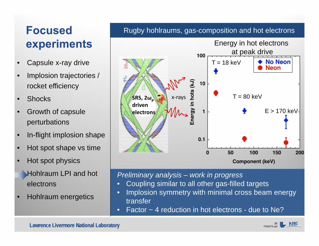
Preliminary analysis – work in progress• Coupling similar to all other gas-filled targets• Implosion symmetry with minimal cross beam energy
transfer• Factor ~ 4 reduction in hot electrons - due to Ne?
Rugby hohlraums, gas-composition and hot electronsFocused experiments
T = 18 keV
T = 80 keV
E > 170 keV
x‐raysSRS, 2ωpdriven electrons
Energy in hot electrons at peak drive
• Capsule x-ray drive
• Implosion trajectories / rocket efficiency
• Shocks
• Growth of capsule perturbations
• In-flight implosion shape
• Hot spot shape vs time
• Hot spot physics
• Hohlraum LPI and hot electrons
• Hohlraum energetics

Lawrence Livermore National Laboratory P369476.ppt39
• No LPI - ~ 1% backscatter (vs. ~ 15% in gas-filled)• No drive deficit (vs. ~ 15% in gas-filled)• No cross beam energy transfer
Future experiments will understand effect of gas-fill
Near vacuum hohlraums – energy balanceFocused experiments
Au
CH
window
He
CR ~ 5
X-ray image
- 0.5 1.5 3.5
400
200
0Pow
er (T
W)
time (ns)
DD gas 6.3 mg/cc
120 µm
Ignition capsule
This expt
CHDT• Capsule x-ray drive
• Implosion trajectories / rocket efficiency
• Shocks
• Growth of capsule perturbations
• In-flight implosion shape
• Hot spot shape vs time
• Hot spot physics
• Hohlraum LPI and hot electrons
• Hohlraum energetics

Lawrence Livermore National Laboratory P369476.ppt40
Ignition applications?
Ignition targets need long pulses
Challenge is imploding the capsule symmetrically before hohlraum fills with plasma
Near vacuum hohlraumsFocused experiments
Au
CH
window
He
CR ~ 5
X-ray image
- 0.5 1.5 3.5
400
200
0Pow
er (T
W)
time (ns)
DD gas 6.3 mg/cc
120 µm
Ignition capsule
This expt
CHDT• Capsule x-ray drive
• Implosion trajectories / rocket efficiency
• Shocks
• Growth of capsule perturbations
• In-flight implosion shape
• Hot spot shape vs time
• Hot spot physics
• Hohlraum LPI and hot electrons
• Hohlraum energetics

Lawrence Livermore National Laboratory P369476.ppt41
The high density of diamond (HDC) ablators lead to short laser pulses
≥ 30 kJ
High foot 3-shock ~2.5
Low foot 4-shock~1.5
VacuumGas-filled
2-shock~3 3-shock
~2
HDC CH
≥ 1 MJ≥ 30 kJ
≥ 1 MJ
?
Laser pulse shapes for ignition relevant capsule designs

Lawrence Livermore National Laboratory P369476.ppt42
Initial 2-shock experiments with HDC in near vacuum hohlraums are promising - but more work to do
2013-0000-000.ppt
Preshot *Postshotdrive Expt
Mband fraction(>1.8 keV) 28% 22% 22%
Yield (DD) 1.5e13 2.4e13 2.3e13Tion (keV) 3.3 3.3 3.4Bang time (ns) 7.35 7.75 7.77P0 (µm) 109 101 91Velocity (km/s) 450 430 N/A0
100
200
300
400
500
0 2 4 6
Pow
er (T
W)
time (ns)
N130813 1.3 MJ, 410 TWDelta lambda = 0
* drive adjusted for delivered energy and observed spectrum
UndopedHDC Shell
1000 µm
85 µmDD gas 3.2 mg/cc
X-ray image
• Preserved hohlraum coupling and drive efficiency
• Near 1-D spherical implosion400 µm
N130811 - Key experiment results
But symmetry swings are too large for higher convergence layered implosionsFuture experiments will explore larger hohlraums and other modifications

Lawrence Livermore National Laboratory P369476.ppt43
• For the Hohlraum:• Understand the hohlraum energy balance• Explore ways to develop a more efficient,
predictable hohlraum with better symmetry control (less LPI, CBET)
Future emphasis: improved predictive capability with staged goals towards ignition
• For the Capsule• Understand the “mix cliff”
(velocity, adiabat, surface roughness)• Direct measurement of growth of hydro
instabilities• Improved hot spot mix techniques
• Explore mix mitigation schemes• Verify effects of alpha heating
Capsule instability
Growth x Surface seedsis too large
X-ray push on the capsule is not symmetric enough
Asymmetric hot spot
• For the Capsule and Hohlraum:• Alternate ablators – diamond (HDC), beryllium (Be)• Different capsule/hohlraum pros and cons vs. CH
Development of new experiment techniques, diagnostics and analyses are key to the path forward