Nickel Rim South Mine’s Ventilation on Demand System · 1 Nickel Rim South Mine’s Ventilation...
30
1 Nickel Rim South Mine’s Ventilation on Demand System By Edward M c Laren P. Eng
Transcript of Nickel Rim South Mine’s Ventilation on Demand System · 1 Nickel Rim South Mine’s Ventilation...

1
Nickel Rim South Mine’s Ventilation on Demand
System
By Edward McLaren P. Eng

1

1 General Overview
• Sudbury Integrated Nickel Operations (Sudbury INO) consists of underground mines (Fraser and Nickel Rim South), Strathcona Mill and Sudbury Smelter
• More than 1300 employees
• Nickel-copper mining and processing in the Sudbury area of Northern Ontario, Canada, since 1929
• Nickel and copper are the primary metals; cobalt and precious metals, such as gold, silver, platinum and palladium are also produced
3

1 Recent Safety Milestone
• Achieved 5 million hours without a single lost time injury in our integrated business of exploration, mining, milling and smelting activities
4

1 City of
Sudbury
10km
Fraser Mine
Sudbury Operations

1 2013 Production Rates
• Nickel Rim South Mine
• 1,322,289 ore tonnes mined
• Fraser Mine
• 379,720 ore tonnes mined
• Strathcona Mill
• 2,194,458 ore tonnes milled
• 26,443 tonnes nickel in concentrate
• 55,643 tonnes copper in concentrate
• 607 tonnes cobalt in concentrate
• Sudbury Smelter
• 75,007 tonnes nickel in matte
• 20,531 tonnes copper in matte
• 2,575 tonnes cobalt in matte
6

1 Agenda
Our History
Components of System
How the System Functions
What it Means to Us
Questions
7
1
2
3
4
5

1 Our History
• Mid 1980’s -- Omron Timer’s
• 1 timer per fan
• Schedule programmed in the field
• Early 1990’s – Nano Plc
• Similar to Omron in functionality
• Added benefit of compensating for annual time changes
• Cheaper in cost
• Late 1990’s – Twido PLC by Schneider
• Capable of controlling multiple devises
• Remote communication allowing schedule programming from surface
• Again cheaper in cost
• Mid 2000’s – Energy One by Besteck
• Wonderware based program
• GUI interface
• Remote manual control of the equipment
8

1 Our History
• 2008 – Nickel Rim South Project
• Ventilation on Demand System included in the project
• 2009 – VOD Vendor Selected
• Surface Fans, U/G Regulator & 6 U/G fans automated
• 2010 – Stage 1 & Stage 2
• Remote control achieved, tracking system integrated
• 2011 – Stage 2 & Stage 3
• Dynamic flow control proven on level and exhaust fans
• Ramp break throughs connects mine top to bottom
• 2012 – Stage 2 & Stage 3
• 1220 Level in dynamic control, AQS in 1480-1535 Ramp
• 2013 – Stage 2 & Stage 3
• Main vent infrastructure complete, ramp flow control proven out
9
• Stage 1: Remote/Manual Ventilation Control
• Manual control and event scheduling:
intelligent HMI for surface/remote
control (fans on-off or VFD speed set
point, controllable doors,
regulators/dampers)
• Stage 2: Flow or gas control mode
• Control based on the gas
concentration from sensors as well as
airflow sensors (PID control loop)
• Stage 3: Dynamic VOD
• Flow control via ventilation demand
calculation: as a function of personnel
location and machinery location &
operating status (zone in/out gates
coverage to full tracking coverage)
• Optimization control: air flow
distribution and surface fans energy

2 Components of System - Underground Infrastructure
• Shaft Station PLC
11
Shaft Station PLC’s are located at the main shaft stations on 1280, 1480 & 1660 Levels

2 Components of System - Underground Infrastructure
• Electrical Substations
12
Power Control Centres contain controllable fans starter
Automation Control Centre contains the PLC that communicate with these starters
Automation
Control Centre
(ACC)
Power Control
Centre
(PCC)

2 Components of System - Underground Infrastructure
• Air Monitoring Station
13
The louvers on the regulator are operated using controllable
actuators
Air Monitoring Station contains the PLC that communicate
with these actuator
Sensor Information is feed to the Air Monitoring Station via
4-20mA signals
Flextor Regulator
Gas Sensors
Accutron Flow
Transmitter
PLC Enclosure
Pressure
Transmitter
Actuator
Accutron Flow
Sensor Head Safdy Flow
Sensor

2 Components of System - Underground Infrastructure
• Air Quality Station (AQS) Provides CO sensor, flow sensor and
temperature sensor information only
14
Not part of the original vision
the AQS and AFS were added to the infrastructure once it was
recognized we required sensor information from the ramp areas
Sensor information passed to Automation Control Centre via Ethernet
Gas Sensors
Accutron Flow
Transmitter
• Air Flow Station (AFS) Provides flow sensor and
temperature sensor information only
Similar in appearance,
no gas sensor
on mounting board

2 Components of System - Underground Infrastructure
• Tracking System
15
Network of Wi-Fi Zone zones track Air Demand Indicators, and VOIP phones
based on intensity of signal
Wi-Fi Access Point
Directional
Antenna
Cap Lamp
with ADI Non-Mobile
ADI
Mobile ADI

2 Components of System - Communication Infrastructure
17

3 How the System Functions – Rockwell HMI
18
Rockwell HMI – the base for all site automation
←
←
←
←
Four of the Rockwell Systems together control the mine ventilation
Surface Intake
Surface Exhaust
U/G Auxiliary Fans
Regulators

3
24
VOD HMI – Summary Screen
How the System Functions – VOD HMI
This screen is always open in the back ground
Colours are used to
allow quick system
status determination
Green is good
The darker the green
the higher the level of
control
Yellow indicate control
type problems
Red indicates field
problems
Click to access
Regulator Click to access
Level
Click to access
Level
Click to Log In
Click to access
Scheduling

3 How the System Functions – VOD HMI
25
VOD – Surface Fans: Intake & Exhaust
In Dynamic Control Exhaust Fan speed adjusts to maintain regulators at 80% open or less
Intake and Exhaust Fans can be
set at a given speed (manual) or
a given flow control
Exhaust fan can also be set to
dynamic control
Desired flow in cms through intake fans would be entered here Desired speed in RPM for the exhaust fans would be entered here

3 How the System Functions – VOD HMI
26
Auxiliary fans controls are accessed through their respective level plan
Fan icons are
located on the
heading that they
ventilate, not where
installed
Side bar indicates
status
Green is on
Black is off
Sub Bar provides
mode and fill colour
indicates status
Green is good
Yellow or Red, the fan is
not controllable
Fan Modes
Man – Manual On / Off
VOD – Dynamic Control
Rem – Remote AB Control
Loc – Control in field
Double Click to
access face plate
Click to access
menu

3 How the System Functions – VOD HMI
28
VOD-HMI Regulator Face Plate – accessed off Summary or Level Screen
Left Clicking the SP: box brings
up the Input Dialog box
Allowing Set point
to be changed
Desired flow in cms through regulator, % open if mode is Manual
Regulator Modes
Manual – Louvers opened to % open SP
Flow – Louvers controlled to maintain cms SP
VOD – Louvers controlled meet level demand
SP = Set Point
Click to Select
Desired Mode

3 How the System Functions – VOD HMI
Level Response
• No Activity 8 cms
• 1 Worker 10 cms
• 2 Workers & 1 Utility vehicle 10 cms
» Diesel Demand 6.8 cms
• Level Flow rises to satisfy demand
• 1 Stope Fan operating nothing on the level 23.6cms (min)
Stope Access Response
• Stope Access fan will start within 10 seconds of worker or equipment being 10m inside the access
• Worker is responsible to ensure fan is working
• 15 minutes after the last worker or vehicle leaves the area the fan stops
29
VOD-HMI Scheduling Screen – Dynamic Control

3
What is an Event?
It is a set of
command
instructions to
controllable
equipment
This can include
delay timing, mode,
and set point such
as speed or % open
or on or off or cms
flow
Only one set of
instructions per
piece of equipment
is allowed per event
How the System Functions – VOD HMI
34
VOD-HMI Scheduling Screen – Events
Click on Event to Manage
Then Click “Configure Event”

3 How the System Functions – VOD HMI
35
Scheduling Log reports the success of each events that has been run
VOD-HMI Scheduling Screen – Schedules
What is a Schedule?
It is a command to run an event at a
given time. Schedules are discrete,
subsequent schedules are not
prevented from changing equipment
instructions from previously run
events
13 daily reoccurring User Defined
events for each day shift

3 How the System Functions – Upset Conditions
• Lost Communication (nothing is changed, control removed)
• Restoration of Power
36
Rockwell HMI & VOD HMI Responses
Equipment Rockwell HMI Control to VOD HMI
Surface Fans Mode switches to remote Control Removed
Regulators Mode switches to remote Control Removed
Auxiliary Fans Mode switches to remote Control Removed
Equipment Rockwell HMI Control to VOD HMI VOD in Control
Surface Fans Mode switches to remote Need to re-set Intake fan – resume
Exhaust fan -manual
Regulators Mode switches to remote Need to re-set
Manual
Auxiliary Fans Mode switches to remote Need to re-set
Manual
Mode returns to that just
prior to interruption
Control resumes Manual

3 How the System Functions – VOD HMI
37
VOD-HMI Scheduling Screen – In the Hands of Operations
Action Operations
Centre
Supervisor
Development
Supervisor
Production
Supervisor
Beat
Electrician
Stop/Start U/G
Fans
Take Fan out of
Dynamic Control
Adjust Exhaust
Fan RPM
Start an Event
Postpone Event
Adjust Regulators

3 How the System Functions – VOD HMI
• Regulators were quite capable of realizing demanded flow of 25 cms readily
• Maintaining Ramp flows was more of a challenge than anticipated
• Tried a number of complicated approaches to try to achieve ramp flow
• Found simple approach most reliable
» Regulator that has greatest influence on a given ramp is used to control ramp flows
» Some regulators do influence more than one ramp which can result in over ventilating a given ramp
» Control logic for this method is simple and effective
38
VOD-HMI Scheduling Screen – Ramp Control

3 What it Means to Us
• Continue with expansion of VOD infrastructure
39

4 What it Means to Us
• Information in the hands of operations
• Ability to monitor and stop / start fans remotely
• Ability to monitor and react to upset conditions
• Ability to optimize production blast gas clearing
• Ability to reduce ventilation flow where not required
40
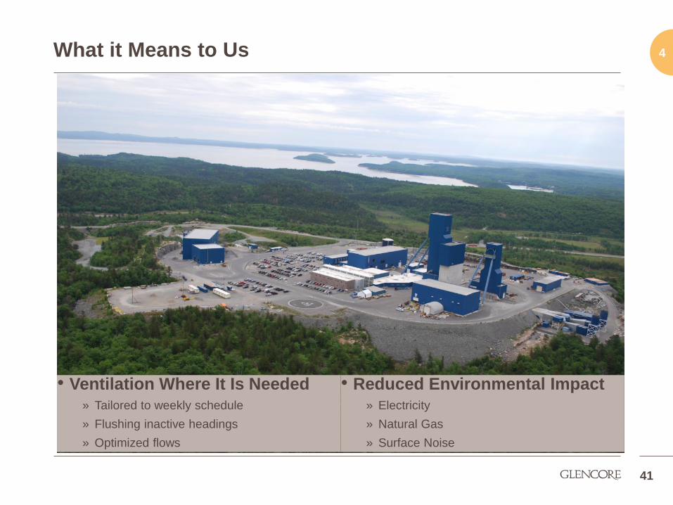
4 What it Means to Us
• Ventilation Where It Is Needed
» Tailored to weekly schedule
» Flushing inactive headings
» Optimized flows
41
• Reduced Environmental Impact
» Electricity
» Natural Gas
» Surface Noise
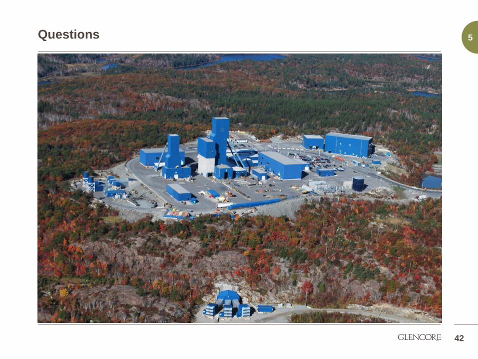
5 Questions
42