NI Software Calibration Management Toolkit for · PDF fileNI Software Calibration Management...
100
NI Software Calibration Management Toolkit for LabVIEW 2013 User's Manual © 2013 National Instruments. All rights reserved. 1 NI Software Calibration Management Toolkit for LabVIEW™ 2013 User's Manual Web : http://www.ni.com/powertrain-controls/ , E-mail : [email protected]
Transcript of NI Software Calibration Management Toolkit for · PDF fileNI Software Calibration Management...

NI Software Calibration Management Toolkit for LabVIEW 2013User's Manual
© 2013 National Instruments. All rights reserved. 1
NI Software Calibration ManagementToolkit for LabVIEW™ 2013
User's Manual
Web : http://www.ni.com/powertrain-controls/, E-mail : [email protected]
NI Software Calibration Management Toolkit for LabVIEW 2013User's Manual
© 2013 National Instruments. All rights reserved. 2
Table of Contents1. Product Introduction ...................................................................................................................................42. Getting Started ...........................................................................................................................................6
2.1 Recommended System Requirements ..............................................................................................72.1 Installing NI SCM ...............................................................................................................................82.2 Activating Your Software ....................................................................................................................9
3. NI SCM Palettes ......................................................................................................................................114. NI SCM Target .........................................................................................................................................12
4.1 Functions Palette ..............................................................................................................................134.2 Basic Framework ..............................................................................................................................194.3 SCM Init VI .......................................................................................................................................204.4 Specifying the Calibration File .........................................................................................................274.5 CalPoints ..........................................................................................................................................294.6 Reserved CalPoints ..........................................................................................................................304.7 CalPoint Configuration Dialogs ........................................................................................................31
4.7.1 SGL, I32, I8, U32, U8 CalPoints .............................................................................................324.7.2 Array CalPoints .......................................................................................................................334.7.3 String CalPoints .......................................................................................................................344.7.4 Boolean CalPoints ...................................................................................................................354.7.5 Lookup Table CalPoints ..........................................................................................................364.7.6 Enumerated CalPoints ............................................................................................................37
4.8 Adapt Points .....................................................................................................................................384.9 Fault Points ......................................................................................................................................394.10 Real-Time Target Setup .................................................................................................................414.11 Building Startup Executable Applications with NI SCM .................................................................424.12 Backup and Restore of a Real-Time System ................................................................................43
5. NI SCM Host ............................................................................................................................................455.1 Controls Palette ................................................................................................................................475.2 Lookup Table Controls .....................................................................................................................48
5.2.1 1D Tables ................................................................................................................................495.2.2 2D Tables ................................................................................................................................52
5.3 CalScope ..........................................................................................................................................545.4 CalTrend ...........................................................................................................................................575.5 Faults ................................................................................................................................................595.6 Other Host VI Tools ..........................................................................................................................60
6. NI SCM Console ......................................................................................................................................616.1 Menu Items .......................................................................................................................................646.2 NI SCM Controls ..............................................................................................................................666.3 Mini Mode .........................................................................................................................................676.4 SCMConfig.ini ...................................................................................................................................686.5 Saving and Loading NI SCM settings ..............................................................................................706.6 Finding a Target ...............................................................................................................................736.7 Pairing CalPoints ..............................................................................................................................766.8 Taking a Snapshot ...........................................................................................................................776.9 CalDiff (Calibration File Difference) .................................................................................................786.10 Calibration File Manager ................................................................................................................80

NI Software Calibration Management Toolkit for LabVIEW 2013User's Manual
© 2013 National Instruments. All rights reserved. 3
6.11 Unit Conversions ............................................................................................................................826.12 Unit Conversion Rules ...................................................................................................................856.13 Example of Unit Conversions ........................................................................................................86
7. Simple Example .......................................................................................................................................877.1 Basic Project Example .....................................................................................................................88
8. Troubleshooting ........................................................................................................................................909. Additional Support/Feedback ...................................................................................................................9310. Important Information .............................................................................................................................94
10.1 Warranty .........................................................................................................................................9510.2 Copyright ........................................................................................................................................9610.3 Trademarks .....................................................................................................................................9710.4 Patents ............................................................................................................................................9810.5 Warning Regarding Use of NI Products ........................................................................................9910.6 Environmental Management ........................................................................................................100
NI Software Calibration Management Toolkit for LabVIEW 2013User's Manual
© 2013 National Instruments. All rights reserved. 4
1. Product IntroductionThe NI Software Calibration Management Toolkit for LabVIEW 2013 is a calibration interface toolkit for efficientlycommunicating and calibrating data parameters (CalPoints) and faults (FaultPoints) between a NI LabVIEW Real-Time target and a host via Ethernet. It provides a user-friendly implementation for real-time target programming andan interface console for pairing real-time target parameters to a NI LabVIEW based host VI. Furthermore, NI SCMsupports ASAM MCD-2 (A2L) file generation and communication with devices over ASAM MCD-3MC (ASAP3).
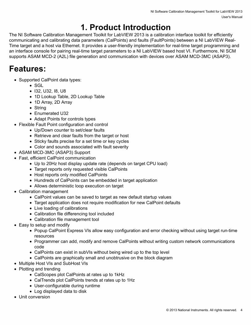
Features:• Supported CalPoint data types:
• SGL• I32, U32, I8, U8• 1D Lookup Table, 2D Lookup Table• 1D Array, 2D Array• String• Enumerated U32• Adapt Points for controls types
• Flexible Fault Point configuration and control• Up/Down counter to set/clear faults• Retrieve and clear faults from the target or host• Sticky faults precise for a set time or key cycles• Color and sounds associated with fault severity
• ASAM MCD-3MC (ASAP3) Support• Fast, efficient CalPoint communication
• Up to 20Hz host display update rate (depends on target CPU load)• Target reports only requested visible CalPoints• Host reports only modified CalPoints• Hundreds of CalPoints can be embedded in target application• Allows deterministic loop execution on target
• Calibration management• CalPoint values can be saved to target as new default startup values• Target application does not require modification for new CalPoint defaults• Live loading of calibrations• Calibration file differencing tool included• Calibration file management tool
• Easy to setup and modify• Popup CalPoint Express VIs allow easy configuration and error checking without using target run-time
resources• Programmer can add, modify and remove CalPoints without writing custom network communications
code• CalPoints can exist in subVIs without being wired up to the top level• CalPoints are graphically small and unobtrusive on the block diagram
• Multiple Host VIs and SubHost VIs• Plotting and trending
• CalScopes plot CalPoints at rates up to 1kHz• CalTrends plot CalPoints trends at rates up to 1Hz• User-configurable during runtime• Log displayed data to disk
• Unit conversion

NI Software Calibration Management Toolkit for LabVIEW 2013User's Manual
© 2013 National Instruments. All rights reserved. 5
• User-specified unit conversions managed on host• User-specified default units and exceptions
• Drag-and-drop, keyboard, or automatic CalPoint pairing• User interface can operate on host using NI LabVIEW Run-Time engine

NI Software Calibration Management Toolkit for LabVIEW 2013User's Manual
© 2013 National Instruments. All rights reserved. 6
2. Getting Started

NI Software Calibration Management Toolkit for LabVIEW 2013User's Manual
© 2013 National Instruments. All rights reserved. 7
2.1 Recommended System Requirements Note: System requirements will vary based on many factors including:
• Number of CalPoints• Communication Rate• Other Running Processes on the Target and Host• Network Traffic
Development Version of NI SCM
Host System
Recommended SystemCPU: 1.6 GHz Multi-core or fasterOS: Microsoft Windows 7/8RAM: 4 GB or moreHard Drive: 10 GB or more free spaceSoftware: • NI LabVIEW Professional Development System 2013
• NI LabVIEW Real-Time Module 2013• NI Software Calibration Management Toolkit for LabVIEW
2013
Display resolution: ≥1920x1080 Deployment Version of NI SCM
Host System
Recommended SystemCPU: 1.6 GHz Multi-core or fasterOS: Microsoft Windows 7/8RAM: 4 GB or moreHard Drive: 10 GB or more free spaceSoftware: • LabVIEW Run-Time Engine 2013
• NI Software Calibration Management Toolkit for LabVIEW2013
Display resolution: ≥1920x1080
NI Software Calibration Management Toolkit for LabVIEW 2013User's Manual
© 2013 National Instruments. All rights reserved. 8
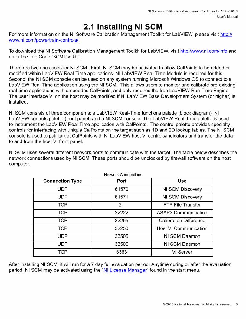
2.1 Installing NI SCMFor more information on the NI Software Calibration Management Toolkit for LabVIEW, please visit http://www.ni.com/powertrain-controls/. To download the NI Software Calibration Management Toolkit for LabVIEW, visit http://www.ni.com/info andenter the Info Code "SCMToolkit". There are two use cases for NI SCM. First, NI SCM may be activated to allow CalPoints to be added ormodified within LabVIEW Real-Time applications. NI LabVIEW Real-Time Module is required for this. Second, the NI SCM console can be used on any system running Microsoft Windows OS to connect to aLabVIEW Real-Time application using the NI SCM. This allows users to monitor and calibrate pre-existingreal-time applications with embedded CalPoints, and only requires the free LabVIEW Run-Time Engine. The user interface VI on the host may be modified if NI LabVIEW Base Development System (or higher) isinstalled. NI SCM consists of three components; a LabVIEW Real-Time functions palette (block diagram), NILabVIEW controls palette (front panel) and a NI SCM console. The LabVIEW Real-Time palette is usedto instrument the LabVIEW Real-Time application with CalPoints. The control palette provides specialtycontrols for interfacing with unique CalPoints on the target such as 1D and 2D lookup tables. The NI SCMconsole is used to pair target CalPoints with NI LabVIEW host VI controls/indicators and transfer the datato and from the host VI front panel. NI SCM uses several different network ports to communicate with the target. The table below describes thenetwork connections used by NI SCM. These ports should be unblocked by firewall software on the hostcomputer.
Network ConnectionsConnection Type Port Use
UDP 61570 NI SCM DiscoveryUDP 61571 NI SCM DiscoveryTCP 21 FTP File TransferTCP 22222 ASAP3 CommunicationTCP 22255 Calibration DifferenceTCP 32250 Host VI CommunicationUDP 33505 NI SCM DaemonUDP 33506 NI SCM DaemonTCP 3363 VI Server
After installing NI SCM, it will run for a 7 day full evaluation period. Anytime during or after the evaluationperiod, NI SCM may be activated using the “NI License Manager” found in the start menu.
NI Software Calibration Management Toolkit for LabVIEW 2013User's Manual
© 2013 National Instruments. All rights reserved. 9
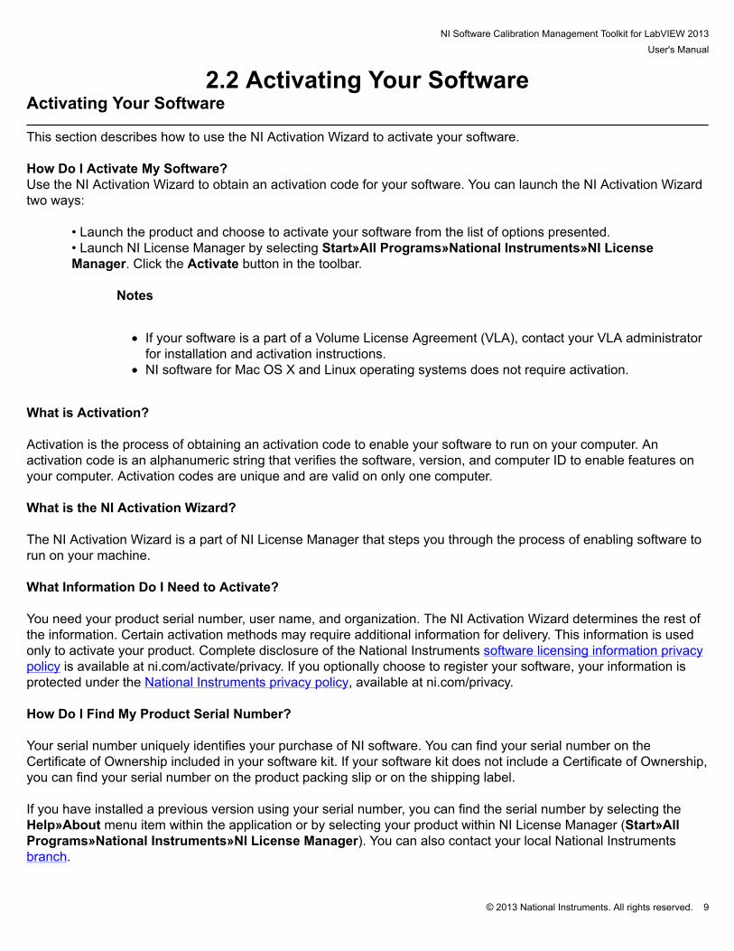
2.2 Activating Your SoftwareActivating Your Software
This section describes how to use the NI Activation Wizard to activate your software. How Do I Activate My Software?Use the NI Activation Wizard to obtain an activation code for your software. You can launch the NI Activation Wizardtwo ways:
• Launch the product and choose to activate your software from the list of options presented.• Launch NI License Manager by selecting Start»All Programs»National Instruments»NI LicenseManager. Click the Activate button in the toolbar.
Notes
• If your software is a part of a Volume License Agreement (VLA), contact your VLA administratorfor installation and activation instructions.
• NI software for Mac OS X and Linux operating systems does not require activation.
What is Activation? Activation is the process of obtaining an activation code to enable your software to run on your computer. Anactivation code is an alphanumeric string that verifies the software, version, and computer ID to enable features onyour computer. Activation codes are unique and are valid on only one computer. What is the NI Activation Wizard? The NI Activation Wizard is a part of NI License Manager that steps you through the process of enabling software torun on your machine. What Information Do I Need to Activate? You need your product serial number, user name, and organization. The NI Activation Wizard determines the rest ofthe information. Certain activation methods may require additional information for delivery. This information is usedonly to activate your product. Complete disclosure of the National Instruments software licensing information privacypolicy is available at ni.com/activate/privacy. If you optionally choose to register your software, your information isprotected under the National Instruments privacy policy, available at ni.com/privacy. How Do I Find My Product Serial Number? Your serial number uniquely identifies your purchase of NI software. You can find your serial number on theCertificate of Ownership included in your software kit. If your software kit does not include a Certificate of Ownership,you can find your serial number on the product packing slip or on the shipping label. If you have installed a previous version using your serial number, you can find the serial number by selecting theHelp»About menu item within the application or by selecting your product within NI License Manager (Start»AllPrograms»National Instruments»NI License Manager). You can also contact your local National Instrumentsbranch.
NI Software Calibration Management Toolkit for LabVIEW 2013User's Manual
© 2013 National Instruments. All rights reserved. 10
What is a Computer ID? The computer ID contains unique information about your computer. National Instruments requires this informationto enable your software. You can find your computer ID through the NI Activation Wizard or by using NI LicenseManager, as follows:
1. Launch NI License Manager by selecting Start»All Programs»National Instruments»NI LicenseManager.2. Click the Display Computer Information button in the toolbar.
For more information about product activation and licensing, refer to ni.com/activate. How Can I Evaluate NI Software?You can install and run most NI application software in evaluation mode. This mode lets you use a product withcertain limitations, such as reduced functionality or limited execution time. Refer to your product documentation forspecific information on the product’s evaluation mode. Moving Software After Activation To transfer your software to another computer, install and activate it on the second computer. You are not prohibitedfrom transferring your software from one computer to another and you do not need to contact or inform NI of thetransfer. Because activation codes are unique to each computer, you will need a new activation code. Refer to HowDo I Activate My Software? to acquire a new activation code and reactivate your software. Deactivating a Product To deactivate a product and return the product to the state it was in before you activated it, right- click the product inthe NI License Manager tree and select Deactivate. If the product was in evaluation mode before youactivated it, theproperties of the evaluation mode may not be restored. Using Windows Guest AccountsNI License Manager does not support Microsoft Windows Guest accounts. You must log in to a non-Guest accountto run licensed NI application software.

NI Software Calibration Management Toolkit for LabVIEW 2013User's Manual
© 2013 National Instruments. All rights reserved. 11
3. NI SCM PalettesNI SCM installs two types of palettes into NI LabVIEW, the first is the functions palettes which contain allthe subVIs required to create a NI SCM target and add extra functionality to the host. The second palette isthe controls pallet which contains controls needed to add certain functionality to a NI SCM host.

NI Software Calibration Management Toolkit for LabVIEW 2013User's Manual
© 2013 National Instruments. All rights reserved. 12
4. NI SCM Target
NI Software Calibration Management Toolkit for LabVIEW 2013User's Manual
© 2013 National Instruments. All rights reserved. 13
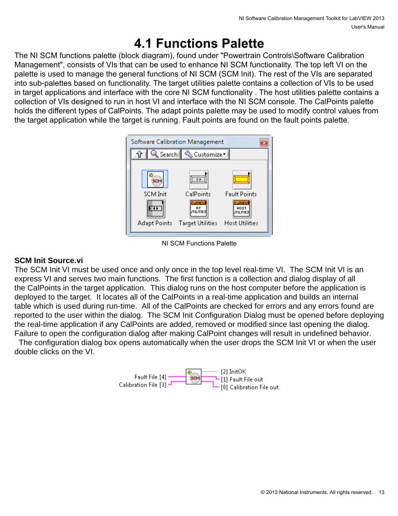
4.1 Functions PaletteThe NI SCM functions palette (block diagram), found under "Powertrain Controls\Software CalibrationManagement", consists of VIs that can be used to enhance NI SCM functionality. The top left VI on thepalette is used to manage the general functions of NI SCM (SCM Init). The rest of the VIs are separatedinto sub-palettes based on functionality. The target utilities palette contains a collection of VIs to be usedin target applications and interface with the core NI SCM functionality . The host utilities palette contains acollection of VIs designed to run in host VI and interface with the NI SCM console. The CalPoints paletteholds the different types of CalPoints. The adapt points palette may be used to modify control values fromthe target application while the target is running. Fault points are found on the fault points palette.
NI SCM Functions Palette
SCM Init Source.viThe SCM Init VI must be used once and only once in the top level real-time VI. The SCM Init VI is anexpress VI and serves two main functions. The first function is a collection and dialog display of allthe CalPoints in the target application. This dialog runs on the host computer before the application isdeployed to the target. It locates all of the CalPoints in a real-time application and builds an internaltable which is used during run-time. All of the CalPoints are checked for errors and any errors found arereported to the user within the dialog. The SCM Init Configuration Dialog must be opened before deployingthe real-time application if any CalPoints are added, removed or modified since last opening the dialog. Failure to open the configuration dialog after making CalPoint changes will result in undefined behavior. The configuration dialog box opens automatically when the user drops the SCM Init VI or when the userdouble clicks on the VI.

NI Software Calibration Management Toolkit for LabVIEW 2013User's Manual
© 2013 National Instruments. All rights reserved. 14
Target Utilities PaletteRead CalFile.viThis VI reads the data from a calibration file. It may be used on the target to evaluate calibration data.
Save CalFile.viThis VI saves a Calibration file in the default data directory. "Calibration File" should be set to the desiredcalibration file name without a file extension. Alternatively, "Calibration File" may be set to a plane text file(*.txt including the file extension) which points to the calibration file.If "Controls Only" is set to TRUE, only CalPoint Controls will be saved in the calibration file. Otherwise, allCalPoints will be saved. This feature creates a smaller calibration file, especially when using large arrayindicators.The "Saved File" indicator returns the final saved file name.
Load CalFile.viThis VI loads a Calibration file from the default data directory while the target is running. The programshould verify that the I/O is in a safe state before proceeding with loading a calibration file on a runningtarget. Failure to lock the I/O properly could result in dangerous states. Live loading of calibration files mustbe enabled in SCM Init and the confirm I/O Lock must be true.
Read Fault File.viThis VI reads the data from a fault file. It may be used on the target to evaluate fault data.

NI Software Calibration Management Toolkit for LabVIEW 2013User's Manual
© 2013 National Instruments. All rights reserved. 15
Save Fault File.viThis VI saves a Fault file in the default data directory. "Fault File" should be set to the desired Fault filename without a file extension.The "Saved File" indicator returns the final saved file name.
Get Faults.viThis VI is used to get the current CalPoint Values. It should only be run on a running target.
Request IO Lock.viThis VI reports the request for a hardware I/O lock so that a calibration file may be loaded without a restart.After the hardware I/O lock has been completed, use the confirm I/O Lock to proceed with loading thecalibration file.
Confirm IO Lock.viThis VI is used to confirm that the hardware I/O has been locked so that the calibration file can be loadedwithout restarting the application. The hardware I/O lock prevents undesired events during calibration filetransition. Warning: The user application must lock the hardware before setting the confirm hardware I/O lock. Failureto do so may result in undesired events.

NI Software Calibration Management Toolkit for LabVIEW 2013User's Manual
© 2013 National Instruments. All rights reserved. 16
Host Utilities Palette
SCM Console Button.viThis VI is to be used in the host VI and "presses" some of the buttons on the SCM console as if the userpresses the button. This can be used to exit the user interface and NI SCM console or save a calibrationfile.
FTP Browser.viThis VI uses the FTP client to browse a remote file system and creates a local path for the remote machineto use. This VI should be used in the host application and not in the target application. The LabVIEWInternet Toolkit must be installed for this VI to work as a part of the LabVIEW development environment.
Get Console Messages.viThis VI is to be used in the host VI. It returns all the messages displayed on the Software CalibrationManager console. The messages can then be translated to the messages displayed in the SoftwareCalibration Manager console.
Translate Console Messages.viThis VI is to be used in the host VI. It translates a message number into the messages displayed in the NISCM console.
NI Software Calibration Management Toolkit for LabVIEW 2013User's Manual
© 2013 National Instruments. All rights reserved. 17
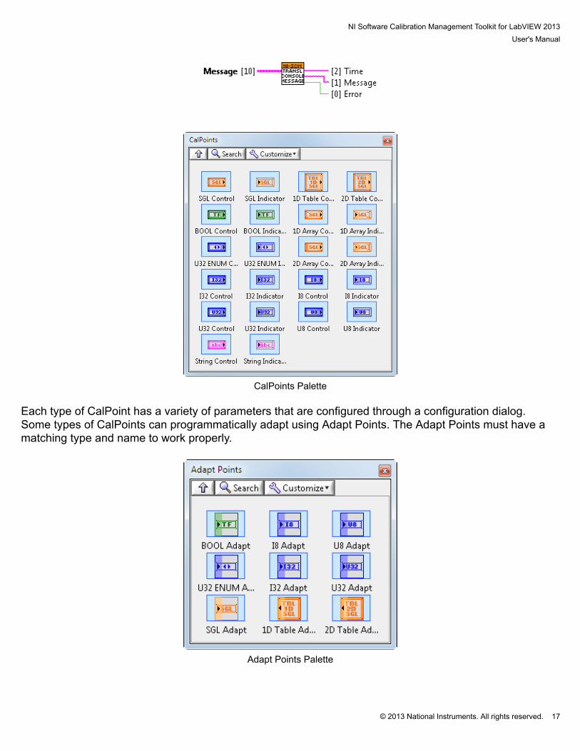
CalPoints Palette
Each type of CalPoint has a variety of parameters that are configured through a configuration dialog. Some types of CalPoints can programmatically adapt using Adapt Points. The Adapt Points must have amatching type and name to work properly.
Adapt Points Palette
NI Software Calibration Management Toolkit for LabVIEW 2013User's Manual
© 2013 National Instruments. All rights reserved. 18
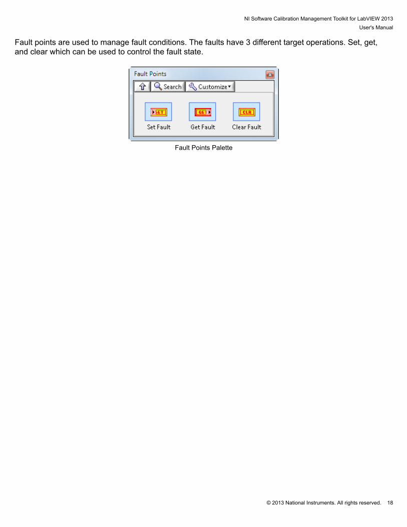
Fault points are used to manage fault conditions. The faults have 3 different target operations. Set, get,and clear which can be used to control the fault state.
Fault Points Palette

NI Software Calibration Management Toolkit for LabVIEW 2013User's Manual
© 2013 National Instruments. All rights reserved. 19
4.2 Basic FrameworkA NI SCM target VI must use a basic framework in order to work properly. The framework starts with theSCM Init VI controlling a case structure. The case structure true state then contains all the user code.
Basic Target Structure
NI Software Calibration Management Toolkit for LabVIEW 2013User's Manual
© 2013 National Instruments. All rights reserved. 20
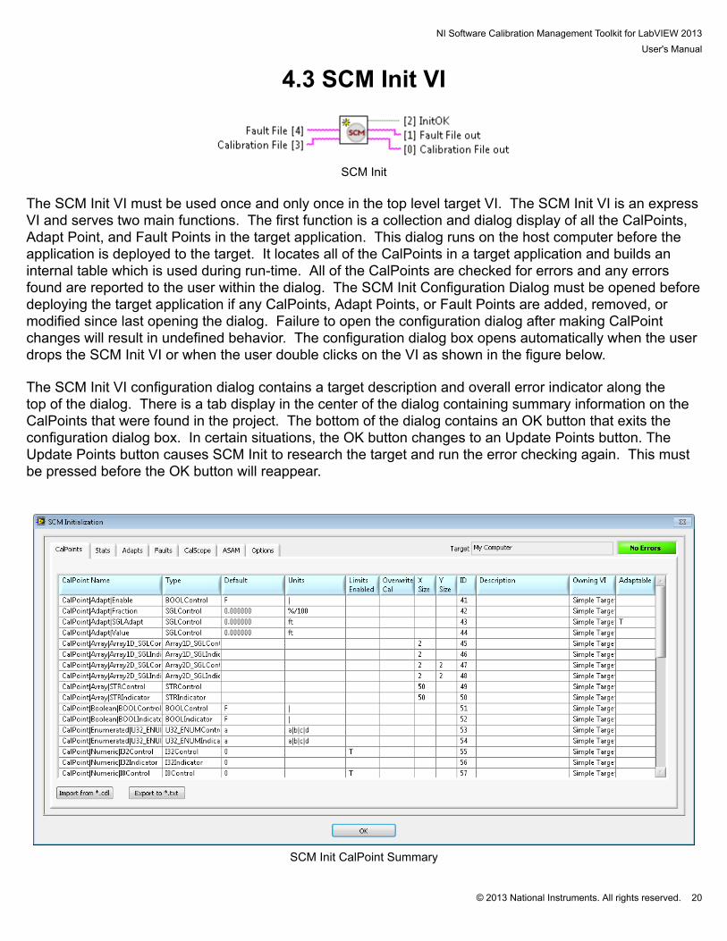
4.3 SCM Init VI
SCM Init
The SCM Init VI must be used once and only once in the top level target VI. The SCM Init VI is an expressVI and serves two main functions. The first function is a collection and dialog display of all the CalPoints,Adapt Point, and Fault Points in the target application. This dialog runs on the host computer before theapplication is deployed to the target. It locates all of the CalPoints in a target application and builds aninternal table which is used during run-time. All of the CalPoints are checked for errors and any errorsfound are reported to the user within the dialog. The SCM Init Configuration Dialog must be opened beforedeploying the target application if any CalPoints, Adapt Points, or Fault Points are added, removed, ormodified since last opening the dialog. Failure to open the configuration dialog after making CalPointchanges will result in undefined behavior. The configuration dialog box opens automatically when the userdrops the SCM Init VI or when the user double clicks on the VI as shown in the figure below. The SCM Init VI configuration dialog contains a target description and overall error indicator along thetop of the dialog. There is a tab display in the center of the dialog containing summary information on theCalPoints that were found in the project. The bottom of the dialog contains an OK button that exits theconfiguration dialog box. In certain situations, the OK button changes to an Update Points button. TheUpdate Points button causes SCM Init to research the target and run the error checking again. This mustbe pressed before the OK button will reappear.
SCM Init CalPoint Summary

NI Software Calibration Management Toolkit for LabVIEW 2013User's Manual
© 2013 National Instruments. All rights reserved. 21
The summary table contains a list of all the CalPoints found within the target along with most of theirproperties. The list is sorted in alphabetical order based on the CalPoints’ full name. Double clicking on aCalPoint will open the CalPoint Configuration dialog box and allow changes to be made. Importing a *.cdl file allows the user to apply default values from a calibration file to apply to the defaultvalues of the CalPoints. Exporting the table to a *.txt file, creates a tab delineated text file of the table. This table is used to simulate a target in the NI SCM console in order to create a pairing file without arunning target. Below is a summary of each column and the information it contains. CalPoint Name: Reports the names of the CalPoints. Type: Reports the data type and direction of the CalPoint. Default: Reports the default value that will be used by the CalPoint if no calibration file is found on thetarget, or if this particular CalPoint is not found in the calibration. Units: Reports the units of the CalPoint entered in the configuration dialog. Limits Enabled: Reports “T” if non-default limits are defined in the CalPoint configuration dialog. Overwrite Cal: Reports “T” if the “Overwrite Cal” option is enabled within the CalPoint configurationdialog. This setting determines whether the default value is used during application startup, regardless ofthe value contained in the calibration file. X Size: Reports the X size of a lookup table or array entered in the CalPoint configuration dialog. Y Size: Reports the Y size of a lookup table or array entered in the CalPoint configuration dialog. ID: Reports a unique CalPoint ID assigned to each CalPoint. Description: Reports the description entered in the CalPoint configuration dialog. Owning VI: Reports the VI name which contains the CalPoint. This is useful to debug any errors in theCalPoints. Adaptable: Reports if an Adapt Point is set up to adapt the CalPoint.
NI Software Calibration Management Toolkit for LabVIEW 2013User's Manual
© 2013 National Instruments. All rights reserved. 22
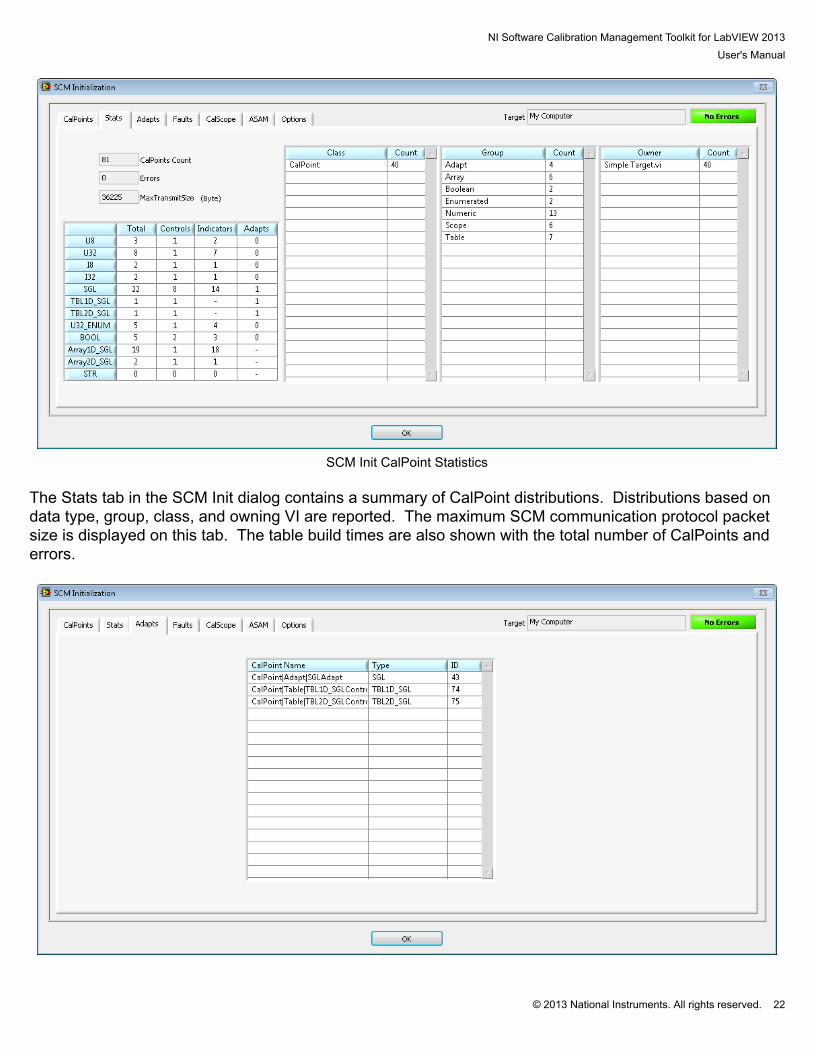
SCM Init CalPoint Statistics
The Stats tab in the SCM Init dialog contains a summary of CalPoint distributions. Distributions based ondata type, group, class, and owning VI are reported. The maximum SCM communication protocol packetsize is displayed on this tab. The table build times are also shown with the total number of CalPoints anderrors.

NI Software Calibration Management Toolkit for LabVIEW 2013User's Manual
© 2013 National Instruments. All rights reserved. 23
SCM Init Adapt Point Summary
The Adapt tab displays a list of all the Adapt Points found in the project. The associated type and IDnumber are also displayed to allow easy identification of the associated CalPoint. Double clicking on aCalPoint will open the Adapt Point Configuration dialog box and allow changes to be made.
SCM Init Fault Point Summary
The Fault Point tab in the SCM Init dialog contains the summary of all fault points found on the target.Double clicking on a Fault Point will open the CalPoint Configuration dialog box and allow changes to bemade.
NI Software Calibration Management Toolkit for LabVIEW 2013User's Manual
© 2013 National Instruments. All rights reserved. 24
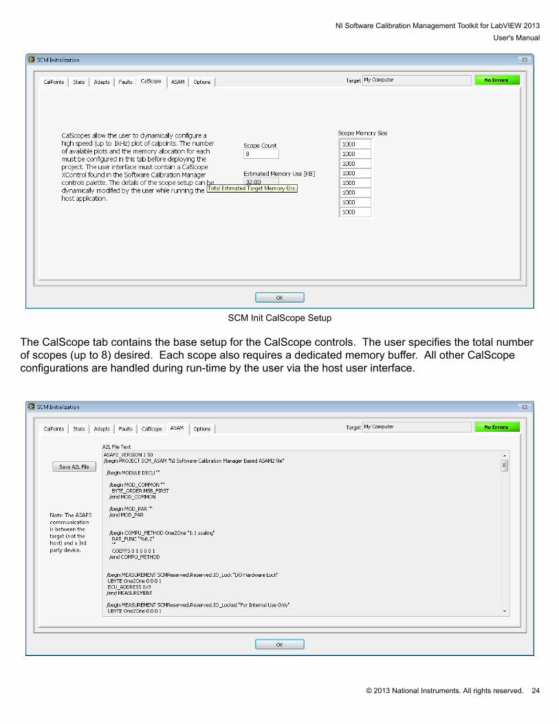
SCM Init CalScope Setup
The CalScope tab contains the base setup for the CalScope controls. The user specifies the total numberof scopes (up to 8) desired. Each scope also requires a dedicated memory buffer. All other CalScopeconfigurations are handled during run-time by the user via the host user interface.
NI Software Calibration Management Toolkit for LabVIEW 2013User's Manual
© 2013 National Instruments. All rights reserved. 25
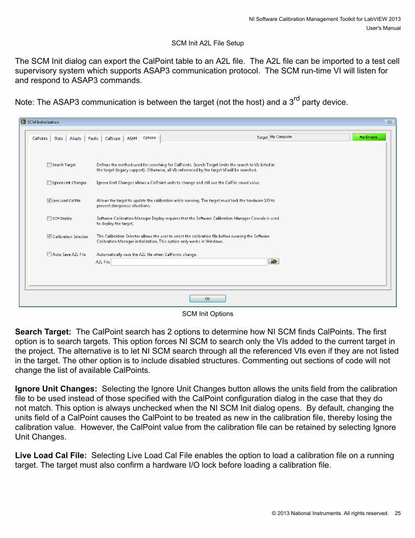
SCM Init A2L File Setup The SCM Init dialog can export the CalPoint table to an A2L file. The A2L file can be imported to a test cellsupervisory system which supports ASAP3 communication protocol. The SCM run-time VI will listen forand respond to ASAP3 commands.
Note: The ASAP3 communication is between the target (not the host) and a 3rd party device.
SCM Init Options
Search Target: The CalPoint search has 2 options to determine how NI SCM finds CalPoints. The firstoption is to search targets. This option forces NI SCM to search only the VIs added to the current target inthe project. The alternative is to let NI SCM search through all the referenced VIs even if they are not listedin the target. The other option is to include disabled structures. Commenting out sections of code will notchange the list of available CalPoints. Ignore Unit Changes: Selecting the Ignore Unit Changes button allows the units field from the calibrationfile to be used instead of those specified with the CalPoint configuration dialog in the case that they donot match. This option is always unchecked when the NI SCM Init dialog opens. By default, changing theunits field of a CalPoint causes the CalPoint to be treated as new in the calibration file, thereby losing thecalibration value. However, the CalPoint value from the calibration file can be retained by selecting IgnoreUnit Changes. Live Load Cal File: Selecting Live Load Cal File enables the option to load a calibration file on a runningtarget. The target must also confirm a hardware I/O lock before loading a calibration file.
NI Software Calibration Management Toolkit for LabVIEW 2013User's Manual
© 2013 National Instruments. All rights reserved. 26
SCM Deploy: Selecting SCM Deploy forces the user to deploy the VI from the NI SCM consol. Thisguarantees that SCM Init runs before deploying. If the target is deployed by pressing the run button, thetarget initialization will fail. Selecting this option will cause built applications to fail and should not be usedwith built applications. Calibration Selector: Selecting Calibration Selector enables a calibration selection dialog box on targetstartup. This option only applies to Microsoft Windows targets. AutoSave A2L: Selecting AutoSave A2L file causes the specified A2L file to save each time the SCM Initsearches for CalPoints. The second function of the SCM Init VI is to initialize the CalPoints and the Fault Points throughout theapplication and prepare for communications with the host. During application startup, the SCM Init VIloads the calibration values from the specified “Calibration File” located in the file system of the target. Thecalibration file contains each CalPoint Name, Group, Class, Units, and Value. SCM Init also initializes thefaults to their last known state. The state of the faults is constantly saved to a user specified file at a userspecified rate. The file only contains the most recent stare of the faults. During application startup, if the initialization finishes without any errors, the “InitOK” output is set to true. Only if the “InitOK” is true should any other part of the application be allowed to run. Allowing CalPoints torun with a false “InitOK” may cause the system behavior to be unpredictable. “InitOK” will be false if SCMInit reports an error within the CalPoint table and the error is not resolved before running the application.
NI Software Calibration Management Toolkit for LabVIEW 2013User's Manual
© 2013 National Instruments. All rights reserved. 27
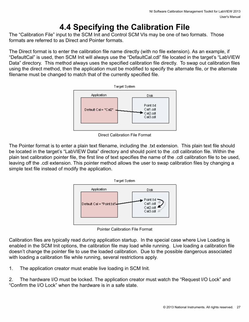
4.4 Specifying the Calibration FileThe “Calibration File” input to the SCM Init and Control SCM VIs may be one of two formats. Thoseformats are referred to as Direct and Pointer formats. The Direct format is to enter the calibration file name directly (with no file extension). As an example, if“DefaultCal” is used, then SCM Init will always use the “DefaultCal.cdl” file located in the target’s “LabVIEWData” directory. This method always uses the specified calibration file directly. To swap out calibration filesusing the direct method, then the application must be modified to specify the alternate file, or the alternatefilename must be changed to match that of the currently specified file.
Direct Calibration File Format
The Pointer format is to enter a plain text filename, including the .txt extension. This plain text file shouldbe located in the target’s “LabVIEW Data” directory and should point to the .cdl calibration file. Within theplain text calibration pointer file, the first line of text specifies the name of the .cdl calibration file to be used,leaving off the .cdl extension. This pointer method allows the user to swap calibration files by changing asimple text file instead of modify the application.
Pointer Calibration File Format
Calibration files are typically read during application startup. In the special case where Live Loading isenabled in the SCM Init options, the calibration file may load while running. Live loading a calibration filedoesn’t change the pointer file to use the loaded calibration. Due to the possible dangerous associatedwith loading a calibration file while running, several restrictions apply. 1. The application creator must enable live loading in SCM Init. 2. The hardware I/O must be locked. The application creator must watch the “Request I/O Lock” and“Confirm the I/O Lock” when the hardware is in a safe state.

NI Software Calibration Management Toolkit for LabVIEW 2013User's Manual
© 2013 National Instruments. All rights reserved. 28
3. The user must understand and accept the risk of loading the calibration file on a running target.
NI Software Calibration Management Toolkit for LabVIEW 2013User's Manual
© 2013 National Instruments. All rights reserved. 29
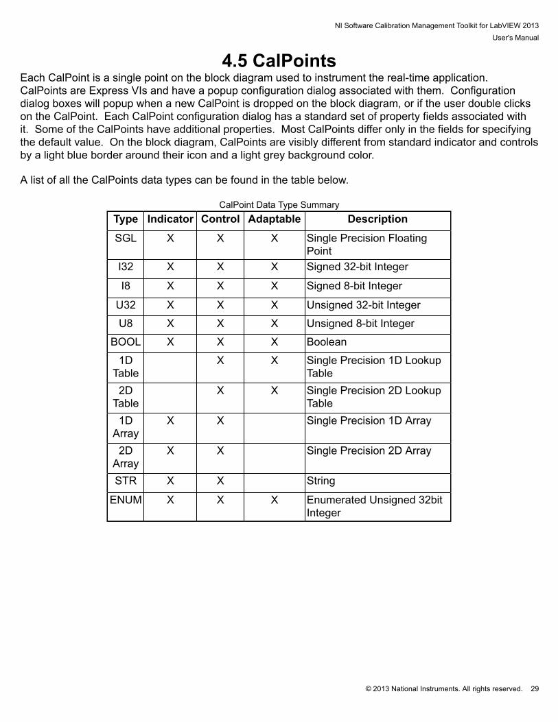
4.5 CalPointsEach CalPoint is a single point on the block diagram used to instrument the real-time application. CalPoints are Express VIs and have a popup configuration dialog associated with them. Configurationdialog boxes will popup when a new CalPoint is dropped on the block diagram, or if the user double clickson the CalPoint. Each CalPoint configuration dialog has a standard set of property fields associated withit. Some of the CalPoints have additional properties. Most CalPoints differ only in the fields for specifyingthe default value. On the block diagram, CalPoints are visibly different from standard indicator and controlsby a light blue border around their icon and a light grey background color. A list of all the CalPoints data types can be found in the table below.
CalPoint Data Type SummaryType Indicator Control Adaptable Description
SGL X X X Single Precision FloatingPoint
I32 X X X Signed 32-bit Integer
I8 X X X Signed 8-bit Integer
U32 X X X Unsigned 32-bit Integer
U8 X X X Unsigned 8-bit Integer
BOOL X X X Boolean
1DTable
X X Single Precision 1D LookupTable
2DTable
X X Single Precision 2D LookupTable
1DArray
X X Single Precision 1D Array
2DArray
X X Single Precision 2D Array
STR X X String
ENUM X X X Enumerated Unsigned 32bitInteger
NI Software Calibration Management Toolkit for LabVIEW 2013User's Manual
© 2013 National Instruments. All rights reserved. 30
4.6 Reserved CalPointsNI SCM automatically reserves a number of CalPoints at the beginning of the CalPoint list. TheseCalPoints contain properties of the target and host. They are also used for special NI SCM functions,such as CalScopes. These CalPoints cannot be modified by the user. However, some of the reservedCalPoints may be connected to indicators on the host panel. The reserved CalPoints are in the“SCMReserved” class and “Reserved” group. User defined CalPoints are not allowed to be in the reservedclass/group. The reserved CalPoints are saved in the calibration files. These may be helpful whenreviewing CalFiles.

NI Software Calibration Management Toolkit for LabVIEW 2013User's Manual
© 2013 National Instruments. All rights reserved. 31
4.7 CalPoint Configuration DialogsBelow is the common property fields associated with each CalPoint. Name: CalPoint name. Group: CalPoint group. Class: CalPoint class. Default Value: Value assumed at application startup if no calibration file is found, or if the named CalPointis not found in the calibration file. Overwrite Default Value: If True, the Default Value is used upon application startup, regardless of thecalibration file value. Units: String that will be displayed within the Caption of paired controls/indicators within the host VI. Enable Limits: Enables limits to be imposed on CalPoint controls (Min, Max, Inc, Dec). Min: Minimum CalPoint value (must be less than the maximum value). Max: Maximum CalPoint value (must be greater than the minimum value). MaxDiff: Maximum differential change in the CalPoint value (must be greater than zero). MaxGrad: Maximum gradient allowed between Table CalPoints (must be greater than zero). Description: Description of the CalPoint is used as the tip strip on the paired control/indicator within thehost VI. Each CalPoint must have a unique Class|Group|Name Combination. The “|” (pipe) character is used as aseparator and should not be used in the Name, Class, Group or Units. Units with multiple parts use the “|”to separate the parts. The “.” character is also reserved. Spaces are permitted but not recommended. Limits and slew rates for U32 and I32 CalPoints are represented internally as float32. Because of this notall 32 bit numbers are available, especially those that cannot be represented in less than 24 bits.
NI Software Calibration Management Toolkit for LabVIEW 2013User's Manual
© 2013 National Instruments. All rights reserved. 32
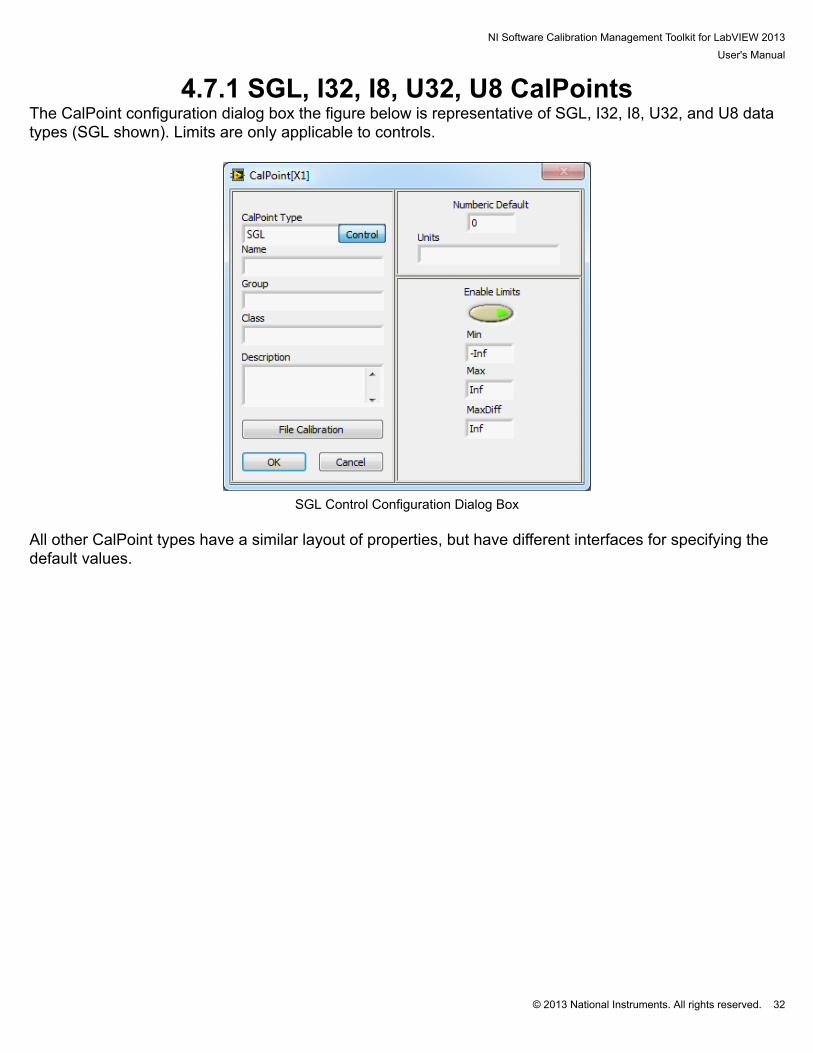
4.7.1 SGL, I32, I8, U32, U8 CalPointsThe CalPoint configuration dialog box the figure below is representative of SGL, I32, I8, U32, and U8 datatypes (SGL shown). Limits are only applicable to controls.
SGL Control Configuration Dialog Box
All other CalPoint types have a similar layout of properties, but have different interfaces for specifying thedefault values.
NI Software Calibration Management Toolkit for LabVIEW 2013User's Manual
© 2013 National Instruments. All rights reserved. 33
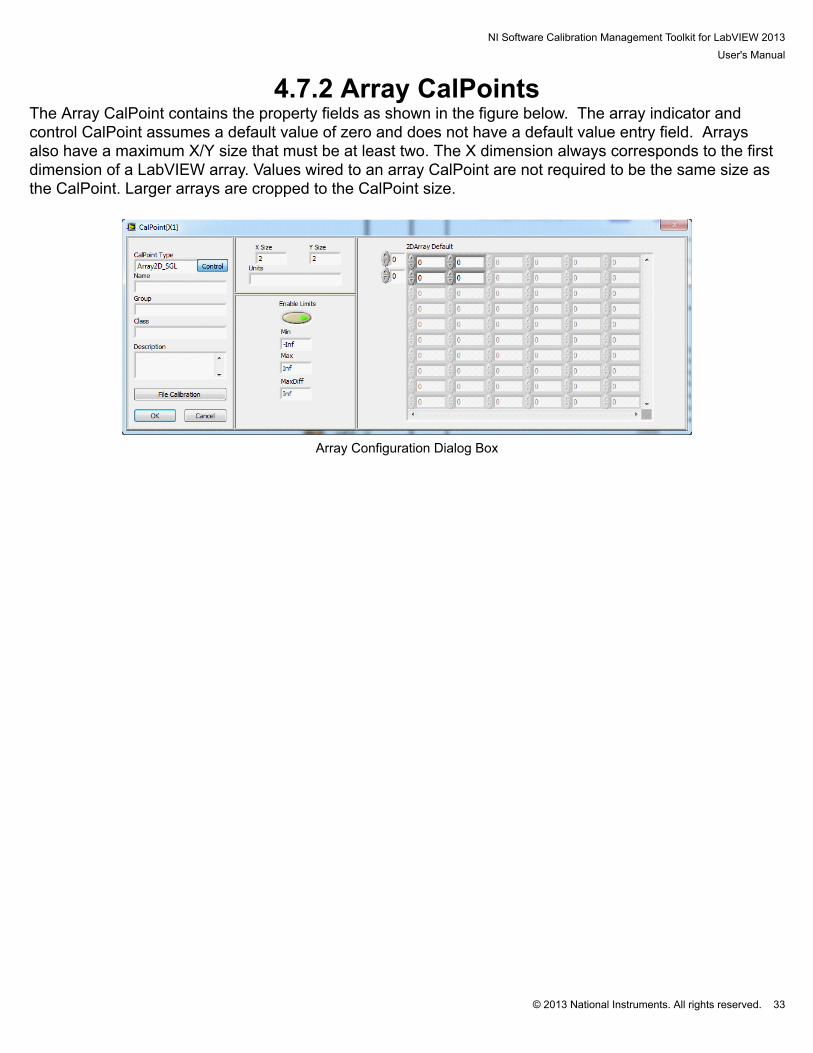
4.7.2 Array CalPointsThe Array CalPoint contains the property fields as shown in the figure below. The array indicator andcontrol CalPoint assumes a default value of zero and does not have a default value entry field. Arraysalso have a maximum X/Y size that must be at least two. The X dimension always corresponds to the firstdimension of a LabVIEW array. Values wired to an array CalPoint are not required to be the same size asthe CalPoint. Larger arrays are cropped to the CalPoint size.
Array Configuration Dialog Box

NI Software Calibration Management Toolkit for LabVIEW 2013User's Manual
© 2013 National Instruments. All rights reserved. 34
4.7.3 String CalPointsThe String CalPoint contains the property fields as shown in the figure below. A String CalPoint does nothave units. Like the array CalPoints, the user must specify a maximum size. If the data is larger than themaximum size, the data is cropped at the maximum length.
String Configuration Dialog Box

NI Software Calibration Management Toolkit for LabVIEW 2013User's Manual
© 2013 National Instruments. All rights reserved. 35
4.7.4 Boolean CalPointsThe Boolean CalPoint contains the property fields as shown in the figure below. A Boolean CalPointdoes not have units, but instead has True and False labels. The strings in the True and False fields areseparated by a “|” in all summary displays. The strings entered for these fields show up as the Booleantext on the paired Boolean on the host VI front panel. Paired Boolean controls on the host front panel mustbe set to switch mechanical action and not latching. Boolean controls have a one shot function whichprovides a single true output after being set. The display control will also reset after the one shot fires.
Boolean Configuration Dialog Box
NI Software Calibration Management Toolkit for LabVIEW 2013User's Manual
© 2013 National Instruments. All rights reserved. 36
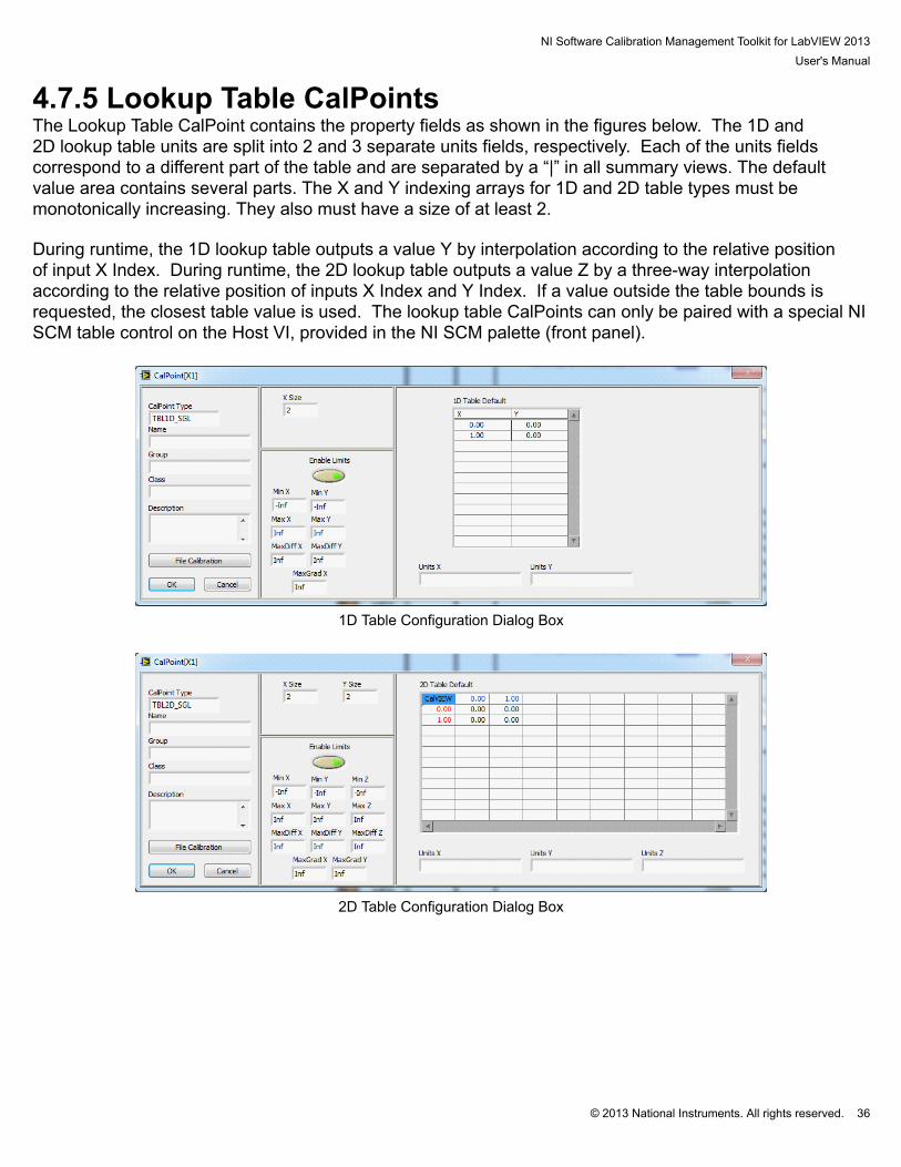
4.7.5 Lookup Table CalPointsThe Lookup Table CalPoint contains the property fields as shown in the figures below. The 1D and2D lookup table units are split into 2 and 3 separate units fields, respectively. Each of the units fieldscorrespond to a different part of the table and are separated by a “|” in all summary views. The defaultvalue area contains several parts. The X and Y indexing arrays for 1D and 2D table types must bemonotonically increasing. They also must have a size of at least 2. During runtime, the 1D lookup table outputs a value Y by interpolation according to the relative positionof input X Index. During runtime, the 2D lookup table outputs a value Z by a three-way interpolationaccording to the relative position of inputs X Index and Y Index. If a value outside the table bounds isrequested, the closest table value is used. The lookup table CalPoints can only be paired with a special NISCM table control on the Host VI, provided in the NI SCM palette (front panel).
1D Table Configuration Dialog Box
2D Table Configuration Dialog Box
NI Software Calibration Management Toolkit for LabVIEW 2013User's Manual
© 2013 National Instruments. All rights reserved. 37
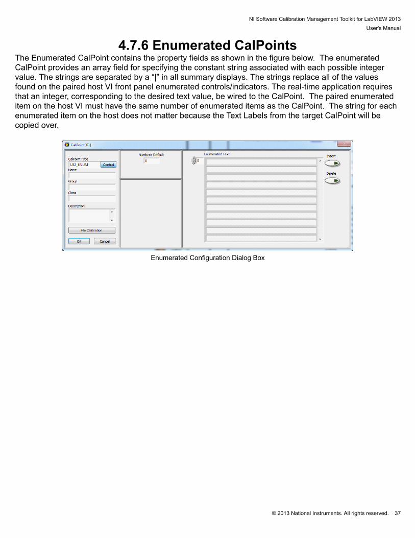
4.7.6 Enumerated CalPointsThe Enumerated CalPoint contains the property fields as shown in the figure below. The enumeratedCalPoint provides an array field for specifying the constant string associated with each possible integervalue. The strings are separated by a “|” in all summary displays. The strings replace all of the valuesfound on the paired host VI front panel enumerated controls/indicators. The real-time application requiresthat an integer, corresponding to the desired text value, be wired to the CalPoint. The paired enumerateditem on the host VI must have the same number of enumerated items as the CalPoint. The string for eachenumerated item on the host does not matter because the Text Labels from the target CalPoint will becopied over.
Enumerated Configuration Dialog Box
NI Software Calibration Management Toolkit for LabVIEW 2013User's Manual
© 2013 National Instruments. All rights reserved. 38
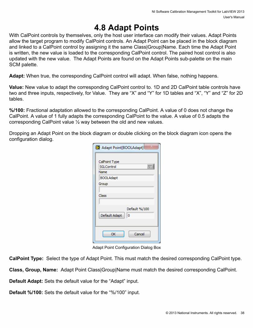
4.8 Adapt PointsWith CalPoint controls by themselves, only the host user interface can modify their values. Adapt Pointsallow the target program to modify CalPoint controls. An Adapt Point can be placed in the block diagramand linked to a CalPoint control by assigning it the same Class|Group|Name. Each time the Adapt Pointis written, the new value is loaded to the corresponding CalPoint control. The paired host control is alsoupdated with the new value. The Adapt Points are found on the Adapt Points sub-palette on the mainSCM palette.
Adapt: When true, the corresponding CalPoint control will adapt. When false, nothing happens. Value: New value to adapt the corresponding CalPoint control to. 1D and 2D CalPoint table controls havetwo and three inputs, respectively, for Value. They are “X” and “Y” for 1D tables and “X”, “Y” and “Z” for 2Dtables. %/100: Fractional adaptation allowed to the corresponding CalPoint. A value of 0 does not change theCalPoint. A value of 1 fully adapts the corresponding CalPoint to the value. A value of 0.5 adapts thecorresponding CalPoint value ½ way between the old and new values. Dropping an Adapt Point on the block diagram or double clicking on the block diagram icon opens theconfiguration dialog.
Adapt Point Configuration Dialog Box
CalPoint Type: Select the type of Adapt Point. This must match the desired corresponding CalPoint type. Class, Group, Name: Adapt Point Class|Group|Name must match the desired corresponding CalPoint. Default Adapt: Sets the default value for the “Adapt” input. Default %/100: Sets the default value for the “%/100” input.

NI Software Calibration Management Toolkit for LabVIEW 2013User's Manual
© 2013 National Instruments. All rights reserved. 39
4.9 Fault PointsFault points have 3 target operations. The first is to set the fault. The fault is based on an up/down counterwhich allows the programmer to specify a delay on setting and clearing the fault. The faults also haveprogrammatic override option to disable the fault. A fault can also set sticky for a number of seconds orkey cycles. A sticky fault will not clear until the up/down counter has been cleared for the specified timeor key cycles. The second fault operation is to get a fault status. The get fault status works with a singlefault, a group of faults, or a class of faults. The get fault status can also return only the unacknowledgedfaults. The last fault operation is to clear faults. The fault clear works with a single fault, a group of faults, ora class of faults. The fault clear can also acknowledge any unacknowledged faults. Dropping an Fault Point on the block diagram or double clicking on the block diagram icon opens theconfiguration dialog.
Fault Point Setup Dialog Box FaultPoint Type: Select the type of Fault Point. Class, Group, Name: Class|Group|Name are used in all types of Fault Point operations. For get and setFault Points Class|Group|Name must match the desired corresponding Fault Point. Leaving the Name orthe Group and Name blank will look at an entire group or class, respectively. Description: Description of the Fault Point is displayed on the host VI fault XControl. Threshold: The threshold is the value where the fault trips. The fault clears at zero. Up Rate: The value at which the up/down counter increases each time the fault set is called and the inputis set to true.

NI Software Calibration Management Toolkit for LabVIEW 2013User's Manual
© 2013 National Instruments. All rights reserved. 40
Down Rate: The value at which the up/down counter decreases each time the fault set is called and theinput is set to false. Sticky: Enable a sticky fault. The fault will not clear until the counter remains at zero for a specified time ornumber of key cycles. Sticky Time: The amount of time required to clear a sticky fault. Sticky Cycles: The number of key cycles required to clear a sticky fault. Severity: The severity group defines what color and alarm sound are associated with the fault.
NI Software Calibration Management Toolkit for LabVIEW 2013User's Manual
© 2013 National Instruments. All rights reserved. 41
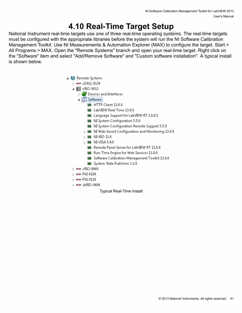
4.10 Real-Time Target SetupNational Instrument real-time targets use one of three real-time operating systems. The real-time targetsmust be configured with the appropriate libraries before the system will run the NI Software CalibrationManagement Toolkit. Use NI Measurements & Automation Explorer (MAX) to configure the target. Start >All Programs > MAX. Open the "Remote Systems" branch and open your real-time target. Right click onthe "Software" item and select "Add/Remove Software" and "Custom software installation". A typical installis shown below.
Typical Real-Time Install
NI Software Calibration Management Toolkit for LabVIEW 2013User's Manual
© 2013 National Instruments. All rights reserved. 42
4.11 Building Startup Executable Applications with NI SCMApplications which use NI SCM can be built into a startup application similar to any other application. Theuser should remember to open the SCM Init dialog before building the application executable so that allCalPoints are located. The user should also make sure to install the required software using MAX.

NI Software Calibration Management Toolkit for LabVIEW 2013User's Manual
© 2013 National Instruments. All rights reserved. 43
4.12 Backup and Restore of a Real-Time SystemNI SCM provides a resource for backing up and restoring real time targets. The tool uses the NI SystemConfiguration tools provided with the NI LabVIEW Real-Time Module and is therefore compatible withother applications built using these tools. The tool may be opened from Start-->All Programs-->NationalInstruments-->Software Calibration Management 2013-->Backup and Restore.
RT Backup and Restore
RT Backup Target
IP Address: Specifies the IP address of the target needing a backup. Target Description: Displays information about the controller (ex. Type). Backup Zip File: Specifies the Zip file to store the real-time target image.
NI Software Calibration Management Toolkit for LabVIEW 2013User's Manual
© 2013 National Instruments. All rights reserved. 44
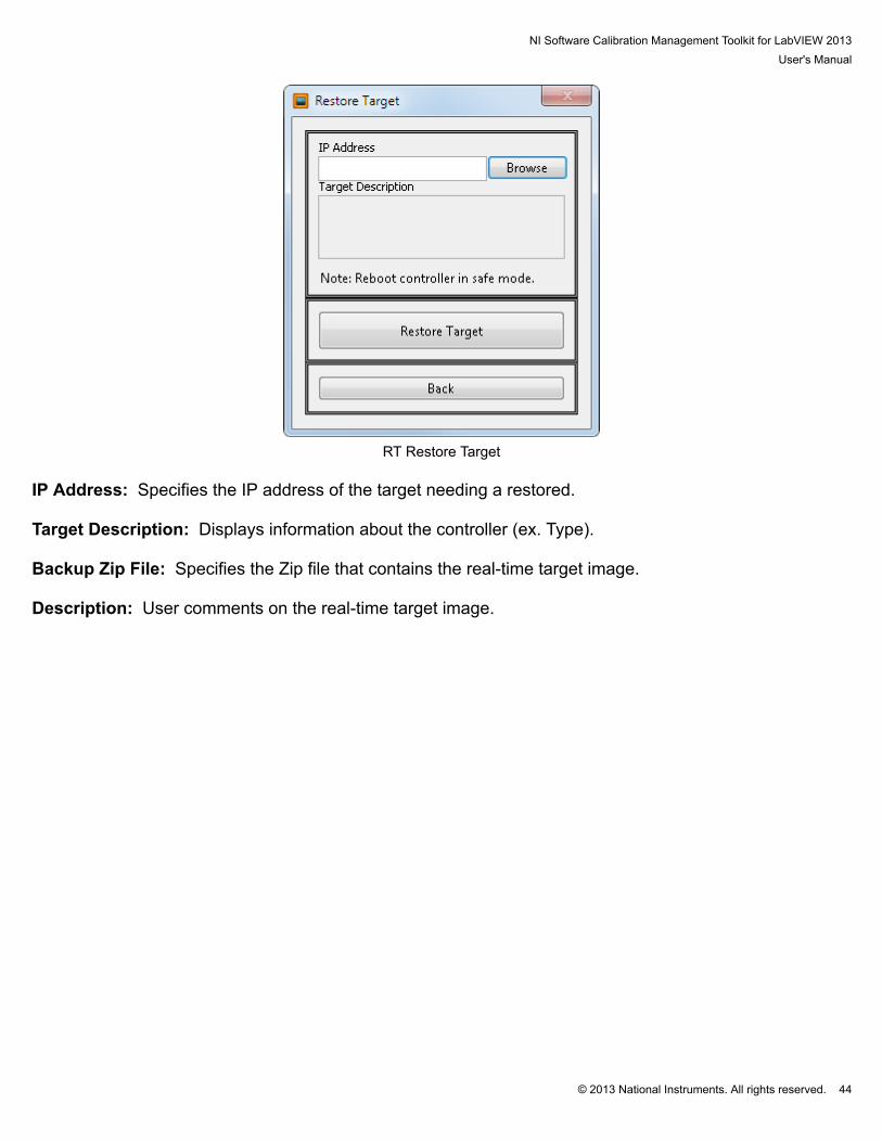
RT Restore Target
IP Address: Specifies the IP address of the target needing a restored. Target Description: Displays information about the controller (ex. Type). Backup Zip File: Specifies the Zip file that contains the real-time target image. Description: User comments on the real-time target image.

NI Software Calibration Management Toolkit for LabVIEW 2013User's Manual
© 2013 National Instruments. All rights reserved. 45
5. NI SCM HostThe host VI is a VI created by the project programmer and acts as the operator interface to the target. The main requirement for the host VI is that it must contain a while loop with a wait period. A waitperiod of 100 msec is recommended. The wait does not set the CalPoint update rate. It only effects theexecution of the code in the host VI. It is not necessary to place anything else inside the loop. Then theprogrammer should create controls and indicators which match the data type of the CalPoints within thetarget application. It is not necessary for the names to be identical; however it does make the task ofpairing target and host controls/indicators for communication easier. Control and indicator names on thehost should only be used once. If the host VI contains two or more controls/indicators with the same name,NI SCM console will only use the first one found. The controls and indicators in the block diagram of thehost VI do not need to be wired to anything. They only need to exist. The NI SCM console will enableyou to make pairings between target CalPoints and these host controls/indicators. Then when you run thehost VI from the NI SCM console, the values will be communicated automatically between the host andthe target. The block diagram shown in the figure below shows a simple host VI with columns of unwiredcontrols and indicators. The code contains a simple loop with a wait command and a waveform chart fora few variables. The CalPoints will update at the update rate set in the NI SCM console but the chart willupdate at the rate of the loop.
Host Block Diagram Indicators in the host VI are only updated with CalPoint indicator values from the target when theyare visible on the host VI front panel. Therefore if you have a tabbed display on the host front panelwith indicators within the tabs, then only the visible tab will have its indicators updated. This helps topreserve communications bandwidth and lowers the target processor demand. If you have a need to writeadditional NI LabVIEW code within the host VI which utilizes CalPoint data (for example logging values tofile), then you need to determine if that value will be visible at all times. If it is within a tab, then it will benecessary to create an additional indicator which can be placed off-screen (but technically always visible). You can make an additional pairing between the CalPoint of interest and this off-screen indicator. Thenyou can create a local variable of this always-visible indicator and use the local variable for any additionalNI LabVIEW coding. CalPoints may be programmatically modified on the host using the Value(signaling) property node. Usingthe Value property node or local variables will change the value on the user interface but it will not causethe value to be written to the target.
NI Software Calibration Management Toolkit for LabVIEW 2013User's Manual
© 2013 National Instruments. All rights reserved. 46
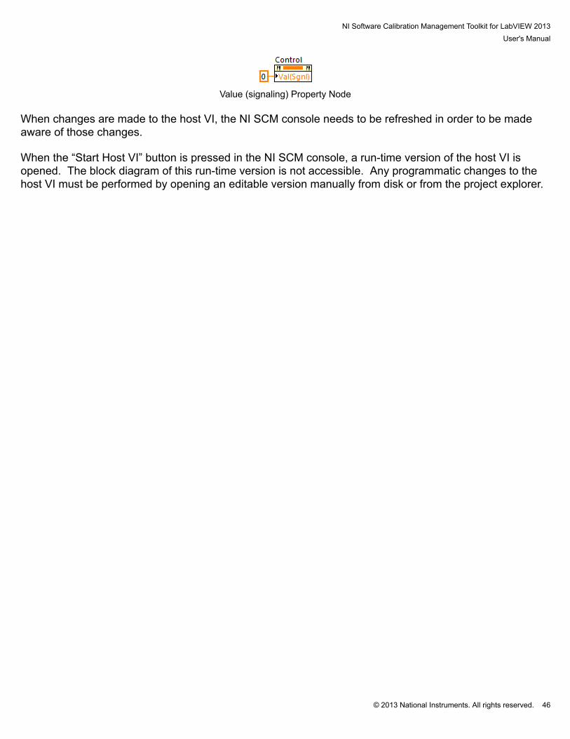
Value (signaling) Property Node When changes are made to the host VI, the NI SCM console needs to be refreshed in order to be madeaware of those changes. When the “Start Host VI” button is pressed in the NI SCM console, a run-time version of the host VI isopened. The block diagram of this run-time version is not accessible. Any programmatic changes to thehost VI must be performed by opening an editable version manually from disk or from the project explorer.
NI Software Calibration Management Toolkit for LabVIEW 2013User's Manual
© 2013 National Instruments. All rights reserved. 47
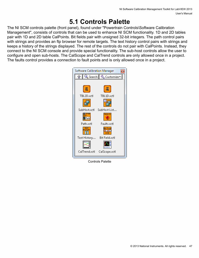
5.1 Controls PaletteThe NI SCM controls palette (front panel), found under "Powertrain Controls\Software CalibrationManagement", consists of controls that can be used to enhance NI SCM functionality. 1D and 2D tablespair with 1D and 2D table CalPoints. Bit fields pair with unsigned 32-bit integers. The path control pairswith strings and provides an ftp browser for remote targets. The text history control pairs with strings andkeeps a history of the strings displayed. The rest of the controls do not pair with CalPoints. Instead, theyconnect to the NI SCM console and provide special functionality. The sub-host controls allow the user toconfigure and open sub-hosts. The CalScope and CalTrend controls are only allowed once in a project.The faults control provides a connection to fault points and is only allowed once in a project.
Controls Palette

NI Software Calibration Management Toolkit for LabVIEW 2013User's Manual
© 2013 National Instruments. All rights reserved. 48
5.2 Lookup Table ControlsNI SCM uses custom XControls to display Lookup Tables on the host VI. The XControl allows advancedviewing and editing options. The control displays the current input and output values along with the lookuptable with the current value highlighted. In addition, the user may directly edit the table values or use a setof built-in functions. A plot of the data is also available. The table controls can be found in the SoftwareCalibration Management palette on the front panel. To view a larger table, simply drag the corners of thecontrol and more cells will be added as room becomes available. Horizontal and vertical scroll bars mayalso be enabled for large tables to be displayed in a small space.
NI Software Calibration Management Toolkit for LabVIEW 2013User's Manual
© 2013 National Instruments. All rights reserved. 49
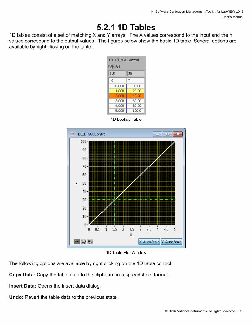
5.2.1 1D Tables1D tables consist of a set of matching X and Y arrays. The X values correspond to the input and the Yvalues correspond to the output values. The figures below show the basic 1D table. Several options areavailable by right clicking on the table.
1D Lookup Table
1D Table Plot Window
The following options are available by right clicking on the 1D table control. Copy Data: Copy the table data to the clipboard in a spreadsheet format. Insert Data: Opens the insert data dialog. Undo: Revert the table data to the previous state.

NI Software Calibration Management Toolkit for LabVIEW 2013User's Manual
© 2013 National Instruments. All rights reserved. 50
Modify Format String: Changes the format of numbers displayed in the table. Enter a valid format string. Please see www.ni.com for details on “Format Specifier Syntax Elements” % Starts format string+ Always show sign (optional)^ Exponent is always a multiple of 3 (optional)# Removes trailing zeros (optional)0 Pad to left with zeros (optional)x Field width (optional) _y y Digits of precision (optional) or.y y Significant digits (optional) e Floating point number with fractional format orf Floating point number with scientific notation org Uses e or f depending on the case orp Floating point number in SI notation Example12.345%.2f = 12.35%_3f = 12.3%.5f = 12.34500%#.5f = 12.345%+f = +12.345%e = 1.234500E+1 Open Plot Window: Opens a popup window with a plot of the table and the current value. Show In and Out Values: Displays the current X input and Y output values from the target at the top tothe table. Show Highlight: Highlights the table value used to calculate the output value. All of the values used arehighlighted in yellow except the closest value. It is highlighted in orange. Show Limits: Shows the value of the limits as well as the current value found in the table. Scale Selection: Scale the current selection by a user specified value. (ex. [2,4,6,11] x 2 = [4,8,12,22]) Scale Difference of Selection: Scale the difference between the first selected value and all the rest ofthe selected points by a user specified value. The first value will not change. This function is equivalent
NI Software Calibration Management Toolkit for LabVIEW 2013User's Manual
© 2013 National Instruments. All rights reserved. 51
to subtracting the first selected value from the array, scaling the array and then adding the original value tothe array. This may be useful if the slope of the table needs to change but the starting point is acceptable. (ex. [2,4,6,11] @ 2x [2,6,10,20]) Straighten Selection: Sets the Y values so that they are defined by a straight line (Y = mX + b) betweenthe first and last value. This function depends on the value of X for each point. The output of this functionwill be a straight line on the table plot. Set Selection Value: Sets all the selected values to a user specified value. (ex. [2,4,8,11] @ 2 = [2,2,2,2]) Space Evenly: Sets the values of all the selected points so that the difference between any twoconsecutive points is equal. The first and last selected values are the only values that affect the finalvalues and do not change. This function returns the same results as the straighten selection if the indexvalues are evenly spaced. (ex. [2,4,6,11] [2,5,8,11], (11-2)/(4-1)=3, a difference of 3 between each point) Vertical Scrollbar: Adds a vertical scrollbar to the table.
NI Software Calibration Management Toolkit for LabVIEW 2013User's Manual
© 2013 National Instruments. All rights reserved. 52
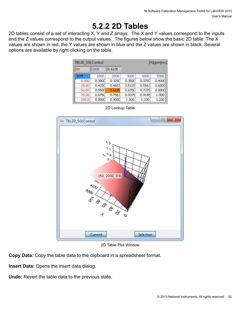
5.2.2 2D Tables2D tables consist of a set of interacting X, Y and Z arrays. The X and Y values correspond to the inputsand the Z values correspond to the output values. The figures below show the basic 2D table. The Xvalues are shown in red, the Y values are shown in blue and the Z values are shown in black. Severaloptions are available by right clicking on the table.
2D Lookup Table
2D Table Plot Window Copy Data: Copy the table data to the clipboard in a spreadsheet format. Insert Data: Opens the insert data dialog. Undo: Revert the table data to the previous state.

NI Software Calibration Management Toolkit for LabVIEW 2013User's Manual
© 2013 National Instruments. All rights reserved. 53
Modify Format String: Changes the format of numbers displayed in the table. Open Plot Window: Opens a popup window with a plot of the table and the current value. Show In and Out Values: Displays the current X and Y inputs values and the Z output value from thetarget at the top to the table. Show Highlight: Highlights the table value used to calculate the output value. All of the values used arehighlighted in yellow except the closest value. It is highlighted in orange. Show Limits: Shows the value of the limits as well as the current value found in the table. Scale Selection: Scale the current selection by a user specified value. (ex. [2,4,6,11] x 2 = [4,8,12,22]) Scale Difference of Selection: Scale the difference between the top left selected point and all the rest ofthe selected points by a user specified value. The top left value will not change. This function is equivalentto subtracting the top left selected value from the array, scaling the array, and then adding the original topleft value to the array. This may be useful if slope of the table needs to change but the starting point isacceptable. (ex. [2,4,6,11] @ 2x [2,6,10,20]) Flatten Selection: Sets the Y values so that they can be defined by a flat surface between the fourselected corners. This function depends on the value of X and Y for each point. The output of this functionwill be a flat surface on the table plot. Set Selection Value: Sets all the selected values to a user specified value. (ex. [2,4,6,11] @ 2x [2,2,2,2]) Space Evenly: Sets the values of all the selected points so that the difference between any twoconsecutive points is equal. The corner values are the only values that affect the final values and donot change. This function returns the same results as the Flatten Selection if the index arrays are evenlyspaced. (ex. [2,4,6,11] [2,5,8,11], (11-2)/(4-1)=3, a difference of 3 between each point) Vertical Scrollbar: Adds a vertical scrollbar to the table. Horizontal Scrollbar: Adds a horizontal scrollbar to the table.

NI Software Calibration Management Toolkit for LabVIEW 2013User's Manual
© 2013 National Instruments. All rights reserved. 54
5.3 CalScopeCalScopes allow the user to dynamically setup and run CalPoint plots. The number of plots and theirassociated memory use must be configured in SCM Init from the real-time target block diagram prior torunning the application. A CalScope XControl must be placed on the host VI front panel. The CalScopeXControl is found in the NI SCM controls palette menu. Only one copy of the CalScope XControl may beuse in a host VI.
CalScope XControl
Clicking in the “Scope Channels” column allows the user to change the name of the scope or changethe CalPoint. The “Memory” column shows the number of samples allocated for each scope and foreach channel in a scope. The memory is set using the SCM Init configuration dialog box. The “Units”column displays the units of the CalPoint as entered in the CalPoint configuration dialog in the real-timeblock diagram. The “Add/Remove” column allows the user to add a CalPoint to the scope by pressingthe + button. Clicking the - button will remove the CalPoint. The “Open” column allows the user to openthe scope window. Scopes that are configured correctly and enabled for opening will have a greenbackground.
NI Software Calibration Management Toolkit for LabVIEW 2013User's Manual
© 2013 National Instruments. All rights reserved. 55
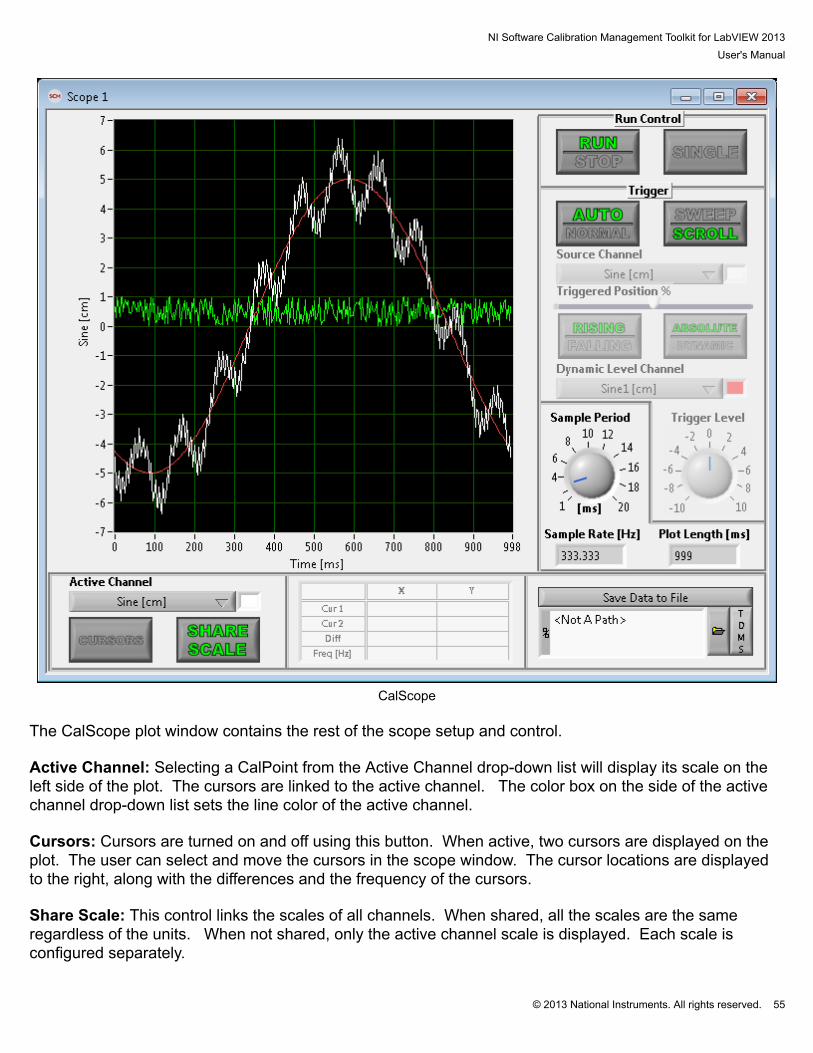
CalScope
The CalScope plot window contains the rest of the scope setup and control. Active Channel: Selecting a CalPoint from the Active Channel drop-down list will display its scale on theleft side of the plot. The cursors are linked to the active channel. The color box on the side of the activechannel drop-down list sets the line color of the active channel. Cursors: Cursors are turned on and off using this button. When active, two cursors are displayed on theplot. The user can select and move the cursors in the scope window. The cursor locations are displayedto the right, along with the differences and the frequency of the cursors. Share Scale: This control links the scales of all channels. When shared, all the scales are the sameregardless of the units. When not shared, only the active channel scale is displayed. Each scale isconfigured separately.

NI Software Calibration Management Toolkit for LabVIEW 2013User's Manual
© 2013 National Instruments. All rights reserved. 56
Save Data To File: Saves the current plot capture to the specified file. Files may be stored in a TDMS orCSV format according to the TDMS/CVS button text shown. Run/Stop: When in Run mode, CalPoints are sampled according to the current trigger configuration. When in Stop mode, all sampling is stopped. Single: Captures a single waveform according to the current trigger configuration and then stops. Auto/Normal: Auto mode continually captures a waveform regardless of the selected trigger source. Inauto mode, all other trigger options are disabled. In Normal mode, data is captured according to the currenttrigger configuration. The location of the trigger is shown by a vertical cursor. Sweep/Scroll: Controls the way the auto mode displays data in the scope window. The display will scrolldata or sweep the new data. Source Channel: Sets the CalPoint used to trigger a new data capture. Triggered Position %: Sets the fraction of the buffer used for pre-trigger data. Rising/Falling: Sets the direction of which the trigger source must pass through the trigger level to triggera new data capture. Absolute/Dynamic: In Absolute mode, Trigger Level is used as the absolute trigger threshold. In Dynamicmode, the CalPoint selected in the Dynamic Level Channel drop-down list is used as the dynamic triggerthreshold. Dynamic Level Channel: Sets the CalPoint used as the dynamic trigger threshold. Trigger Level: Sets the absolute trigger threshold for the Source Channel. Sample Period: Determines the sample period in milliseconds of the data collection. Sample Period mustbe in increments of 1ms. The range may be modified by double-clicking and editing the dial values. Sample Rate: Displays the calculated sample rate in hertz of the data collection according to the selectedSample Period. Plot Length: Displays the calculated length of the data collection and plot window in milliseconds.

NI Software Calibration Management Toolkit for LabVIEW 2013User's Manual
© 2013 National Instruments. All rights reserved. 57
5.4 CalTrendCalTrends provide plotting and configuration similar to CalScopes. The primary difference is thatCalTrends do not need to be configured in SCM Init and they operate at a maximum sample rate of 1Hz. Only one copy of the XControl may be used on a host VI front panel. Only CalPoints paired to host itemsmay be used in a trend.
CalTrend XControl
The CalTrend XControl allows the user to configure up to 8 trend charts. Clicking in the “Trend Channels”column allows the user to change the name of the trend or change the CalPoints. The “Units” columndisplays the units of the CalPoint and may be affected by the unit conversion utility within NI SCM. The“Add/Remove” column allows the user to add a CalPoint to the trend by pressing the + button. Clicking the- button will remove the CalPoint. The “Open” column allows the user to open the chart window. Trendsthat are configured correctly and enabled for opening will have a green background.
NI Software Calibration Management Toolkit for LabVIEW 2013User's Manual
© 2013 National Instruments. All rights reserved. 58
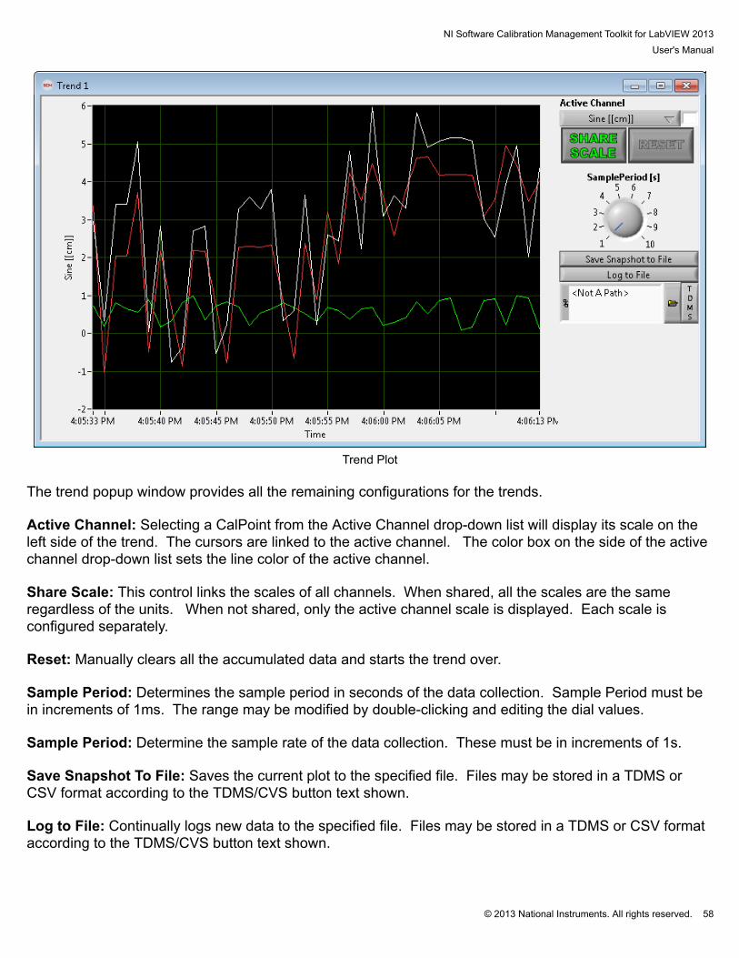
Trend Plot
The trend popup window provides all the remaining configurations for the trends. Active Channel: Selecting a CalPoint from the Active Channel drop-down list will display its scale on theleft side of the trend. The cursors are linked to the active channel. The color box on the side of the activechannel drop-down list sets the line color of the active channel. Share Scale: This control links the scales of all channels. When shared, all the scales are the sameregardless of the units. When not shared, only the active channel scale is displayed. Each scale isconfigured separately. Reset: Manually clears all the accumulated data and starts the trend over. Sample Period: Determines the sample period in seconds of the data collection. Sample Period must bein increments of 1ms. The range may be modified by double-clicking and editing the dial values. Sample Period: Determine the sample rate of the data collection. These must be in increments of 1s. Save Snapshot To File: Saves the current plot to the specified file. Files may be stored in a TDMS orCSV format according to the TDMS/CVS button text shown. Log to File: Continually logs new data to the specified file. Files may be stored in a TDMS or CSV formataccording to the TDMS/CVS button text shown.
NI Software Calibration Management Toolkit for LabVIEW 2013User's Manual
© 2013 National Instruments. All rights reserved. 59
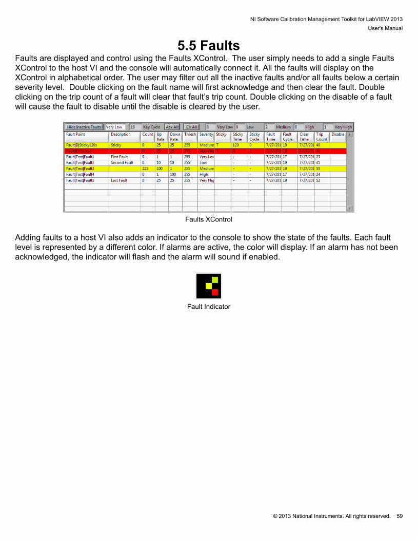
5.5 FaultsFaults are displayed and control using the Faults XControl. The user simply needs to add a single FaultsXControl to the host VI and the console will automatically connect it. All the faults will display on theXControl in alphabetical order. The user may filter out all the inactive faults and/or all faults below a certainseverity level. Double clicking on the fault name will first acknowledge and then clear the fault. Doubleclicking on the trip count of a fault will clear that fault’s trip count. Double clicking on the disable of a faultwill cause the fault to disable until the disable is cleared by the user.
Faults XControl
Adding faults to a host VI also adds an indicator to the console to show the state of the faults. Each faultlevel is represented by a different color. If alarms are active, the color will display. If an alarm has not beenacknowledged, the indicator will flash and the alarm will sound if enabled.
Fault Indicator
NI Software Calibration Management Toolkit for LabVIEW 2013User's Manual
© 2013 National Instruments. All rights reserved. 60
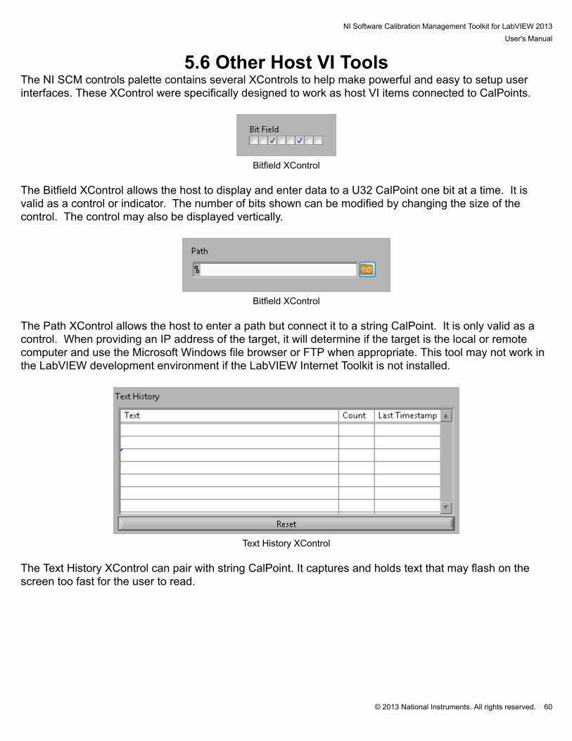
5.6 Other Host VI ToolsThe NI SCM controls palette contains several XControls to help make powerful and easy to setup userinterfaces. These XControl were specifically designed to work as host VI items connected to CalPoints.
Bitfield XControl
The Bitfield XControl allows the host to display and enter data to a U32 CalPoint one bit at a time. It isvalid as a control or indicator. The number of bits shown can be modified by changing the size of thecontrol. The control may also be displayed vertically.
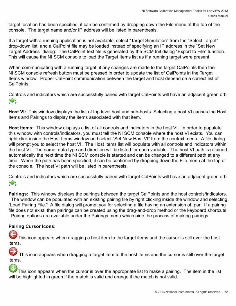
Bitfield XControl
The Path XControl allows the host to enter a path but connect it to a string CalPoint. It is only valid as acontrol. When providing an IP address of the target, it will determine if the target is the local or remotecomputer and use the Microsoft Windows file browser or FTP when appropriate. This tool may not work inthe LabVIEW development environment if the LabVIEW Internet Toolkit is not installed.
Text History XControl
The Text History XControl can pair with string CalPoint. It captures and holds text that may flash on thescreen too fast for the user to read.

NI Software Calibration Management Toolkit for LabVIEW 2013User's Manual
© 2013 National Instruments. All rights reserved. 61
6. NI SCM ConsoleThe NI SCM console application for Microsoft Windows can be found at Start > All Programs > NationalInstruments > Software Calibration Management 2013. The NI SCM console opens the display shownin the figure below. The NI SCM program is the communication link between the host VI and the real-time target. Multiple instances of the NI SCM console may be opened on a single computer to allowcommunication with multiple targets. The instances may be opened using the start menu or using the NISCM Settings File (*.cvsf).
NI SCM Console
NI SCM Console Window Panes: The NI SCM console has four main panels which can be individuallysized: Target Items: This window displays a tree of CalPoints available on the target. The tree structure isorganized according to the Class, Group and Name given to each CalPoint. In order to populate thiswindow with CalPoints, you must tell the NI SCM console where the target exists on the network. Also, anapplication with NI SCM correctly implemented must be running on the target. You can right click insidethe Target Items window and select “Set New Target Address” from the context menu. A dialog will pop-up and make an attempt to find an RT target on the network. If it finds one it will list it in the drop-downlist at the top of the dialog. Otherwise you can type in an IP address of your target. After the target isdiscovered, the Target Items tree will populate. This target location information is retained automaticallythe next time the SCM console is started and can be changed to a different target at any time. When the
NI Software Calibration Management Toolkit for LabVIEW 2013User's Manual
© 2013 National Instruments. All rights reserved. 62
target location has been specified, it can be confirmed by dropping down the File menu at the top of theconsole. The target name and/or IP address will be listed in parenthesis. If a target with a running application is not available, select “Target Simulation” from the “Select Target”drop-down list, and a CalPoint file may be loaded instead of specifying an IP address in the “Set NewTarget Address” dialog. The CalPoint text file is generated by the SCM Init dialog “Export to File” function. This will cause the NI SCM console to load the Target Items list as if a running target were present. When communicating with a running target, if any changes are made to the target CalPoints then theNI SCM console refresh button must be pressed in order to update the list of CalPoints in the TargetItems window. Proper CalPoint communication between the target and host depend on a correct list ofCalPoints. Controls and indicators which are successfully paired with target CalPoints will have an adjacent green orb( ). Host VI: This window displays the list of top level host and sub-hosts. Selecting a host VI causes the HostItems and Pairings to display the items associated with that item. Host Items: This window displays a list of all controls and indicators in the host VI. In order to populatethis window with controls/indicators, you must tell the NI SCM console where the host VI exists. You canright click inside the Host Items window and select “Set New Host VI” from the context menu. A file dialogwill prompt you to select the host VI. The Host Items list will populate with all controls and indicators withinthe host VI. The name, data type and direction will be listed for each variable. The host VI path is retainedautomatically the next time the NI SCM console is started and can be changed to a different path at anytime. When the path has been specified, it can be confirmed by dropping down the File menu at the top ofthe console. The host VI path will be listed in parenthesis. Controls and indicators which are successfully paired with target CalPoints will have an adjacent green orb( ). Pairings: This window displays the pairings between the target CalPoints and the host controls/indicators. The window can be populated with an existing pairing file by right clicking inside the window and selecting“Load Pairing File.” A file dialog will prompt you for selecting a file having an extension of .par. If a pairingfile does not exist, then pairings can be created using the drag-and-drop method or the keyboard shortcuts. Pairing options are available under the Pairings menu which aide the process of making pairings. Pairing Cursor Icons:
This icon appears when dragging a host item to the target items and the cursor is still over the hostitems.
This icon appears when dragging a target item to the host items and the cursor is still over the targetitems.
This icon appears when the cursor is over the appropriate list to make a pairing. The item in the listwill be highlighted in green if the match is valid and orange if the match is not valid.
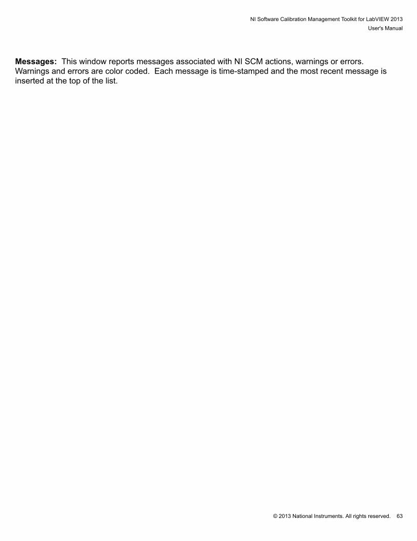
NI Software Calibration Management Toolkit for LabVIEW 2013User's Manual
© 2013 National Instruments. All rights reserved. 63
Messages: This window reports messages associated with NI SCM actions, warnings or errors. Warnings and errors are color coded. Each message is time-stamped and the most recent message isinserted at the top of the list.

NI Software Calibration Management Toolkit for LabVIEW 2013User's Manual
© 2013 National Instruments. All rights reserved. 64
6.1 Menu Items• File:
• Select Target (…): Opens the Select Target dialog.• Select Hosts (…): Opens the Select Host VI dialog.• Save Pairings: Saves the pairing files.• Revert Pairings: Discards current pairings and reloads the pairing files from disk.• Select Units File (…): Opens the Select Units File dialog.• Select Workspace (…): Opens the Select Workspace dialog.• Save Workspace: Saves the workspace.• Select Target VI (…): Opens the Select Target VI dialog.• Select Fault Sounds: Opens the Select Fault Sounds dialog.• Backup Target: Opens the Real-Time Backup/Restore Dialog.• Load Settings: Loads the NI SCM settings file from a file.• Save Settings: Opens the Saves NI SCM settings file dialog.• Exit: Stops communication and exits the program.
• Edit• Open Target: Opens target VI for editing in NI LabVIEW if available.• Open Host VIs: Opens host VI for editing in NI LabVIEW if available.• Edit Units File: Opens the Edit Units dialog.
• Operate:• Mini Mode: Switches the console to mini mode.• Refresh: Reloads the Target Items and Host Items lists and checks the pairings for errors.• Start Host Application: Opens host VI and starts communication.• Stop Host Application: Stops communication and closes host VI.• Stop Target Application: Stops the target application.• Deploy Target: Opens and starts target VI in NI LabVIEW if available.• Silence Alarms: Opens the Silence Alarms dialog.• Set Target Time: Synchronizes target time with host time if available.• Open Communication Statistics: Opens a Communication Statistics Dialog Box.
• Pairings:• Auto Pair Items: Opens a dialog to automatically pair all CalPoints with similar names.• Remove Bad Pairings: Removes all invalid pairings from the pairings list.
• Calibration:• Calibration Difference: Opens the calibration differencing utility.• Calibration Manager: Opens the calibration manager utility.
NI Software Calibration Management Toolkit for LabVIEW 2013User's Manual
© 2013 National Instruments. All rights reserved. 65
• Save Calibration: Saves the default calibration file to the target. The filename is specified bythe “Calibration File” input to the SCM Init VI and is placed in the default data directory on thetarget.
• Save Calibration As …: Saves the calibration file to the target. The filename is specified bythe user input at the prompt and is placed in the default data directory on the target.
• Get Calibration File: Returns the name of the current calibration file in the message window.• Set Calibration File: Changes the current calibration file when using calibration file pointer file
on the target.• Load Calibration File: Loads a calibration file while running if Live Load is enabled.
• Options:• Options: Opens the Options dialog.• Set Fault Update Rate: Opens the Set Fault Update Rate dialog.• Set Communication Time: Opens the Set Communication Time dialog.
• Snapshot:• Output File: Sets the path to the TDMS file to receive CalPoint snapshots.• Log Spec File: Sets the file path to the snapshot log specifications file.• Take Snapshot: Takes a snapshot of the current CalPoint values specified in the log spec file.
• Help:• About: Shows NI SCM version number.• Show Shortcuts: Displays shortcut keys found in SCMConfig.ini.• Open Manual: Opens PDF NI SCM User’s Manual.• Open Website: Opens the National Instruments website in the default web browser.
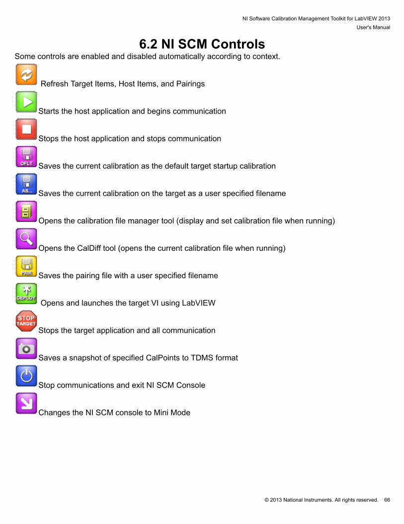
NI Software Calibration Management Toolkit for LabVIEW 2013User's Manual
© 2013 National Instruments. All rights reserved. 66
6.2 NI SCM ControlsSome controls are enabled and disabled automatically according to context.
Refresh Target Items, Host Items, and Pairings
Starts the host application and begins communication
Stops the host application and stops communication
Saves the current calibration as the default target startup calibration
Saves the current calibration on the target as a user specified filename
Opens the calibration file manager tool (display and set calibration file when running)
Opens the CalDiff tool (opens the current calibration file when running)
Saves the pairing file with a user specified filename
Opens and launches the target VI using LabVIEW
Stops the target application and all communication
Saves a snapshot of specified CalPoints to TDMS format
Stop communications and exit NI SCM Console
Changes the NI SCM console to Mini Mode
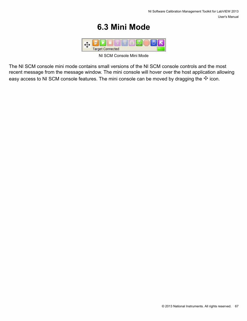
NI Software Calibration Management Toolkit for LabVIEW 2013User's Manual
© 2013 National Instruments. All rights reserved. 67
6.3 Mini Mode
NI SCM Console Mini Mode
The NI SCM console mini mode contains small versions of the NI SCM console controls and the mostrecent message from the message window. The mini console will hover over the host application allowingeasy access to NI SCM console features. The mini console can be moved by dragging the icon.
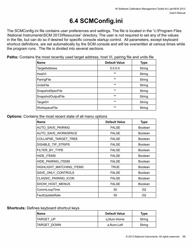
NI Software Calibration Management Toolkit for LabVIEW 2013User's Manual
© 2013 National Instruments. All rights reserved. 68
6.4 SCMConfig.ini The SCMConfig.ini file contains user preferences and settings. The file is located in the “c:\Program Files\National Instruments\SCM 2013\Resources” directory. The user is not required to set any of the valuesin the file, but can do so if desired for specific console startup control. All parameters, except keyboardshortcut definitions, are set automatically by the SCM console and will be overwritten at various times whilethe program runs. The file is divided into several sections. Paths: Contains the most recently used target address, host VI, pairing file and units file
Name Default Value Type
TargetAddress 0.0.0.0 String
HostVI "" String
ParingFile "" String
UnitsFile "" String
SnapshotSpecFile "" String
SnapshotOutputFile "" String
TargetVI "" String
WorkspaceFile "" String Options: Contains the most recent state of all menu options
Name Default Value Type
AUTO_SAVE_PAIRING FALSE Boolean
AUTO_SAVE_WORKSPACE FALSE Boolean
COLLAPSE_TARGET_TREE FALSE Boolean
DISABLE_TIP_STRIPS FALSE Boolean
FILTER_BY_TYPE FALSE Boolean
HIDE_ITEMS FALSE Boolean
HIDE_PAIRING_ITEMS FALSE Boolean
HIGHLIGHT_MATCHING_ITEMS TRUE Boolean
SAVE_ONLY_CONTROLS FALSE Boolean
CLASSIC_PAIRING_ICON FALSE Boolean
SHOW_HOST_MENUS FALSE Boolean
CommLoopTime 50 I32
FaultUpdateRate 50 I32 Shortcuts: Defines keyboard shortcut keys
Name Default Value Type
TARGET_UP q,Num-Home String
TARGET_DOWN a,Num-Left String
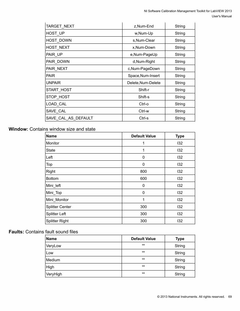
NI Software Calibration Management Toolkit for LabVIEW 2013User's Manual
© 2013 National Instruments. All rights reserved. 69
TARGET_NEXT z,Num-End String
HOST_UP w,Num-Up String
HOST_DOWN s,Num-Clear String
HOST_NEXT x,Num-Down String
PAIR_UP e,Num-PageUp String
PAIR_DOWN d,Num-Right String
PAIR_NEXT c,Num-PageDown String
PAIR Space,Num-Insert String
UNPAIR Delete,Num-Delete String
START_HOST Shift-r String
STOP_HOST Shift-s String
LOAD_CAL Ctrl-o String
SAVE_CAL Ctrl-w String
SAVE_CAL_AS_DEFAULT Ctrl-s String Window: Contains window size and state
Name Default Value Type
Monitor 1 I32
State 1 I32
Left 0 I32
Top 0 I32
Right 800 I32
Bottom 600 I32
Mini_left 0 I32
Mini_Top 0 I32
Mini_Monitor 1 I32
Splitter Center 300 I32
Splitter Left 300 I32
Splitter Right 300 I32 Faults: Contains fault sound files
Name Default Value Type
VeryLow "" String
Low "" String
Medium "" String
High "" String
VeryHigh "" String

NI Software Calibration Management Toolkit for LabVIEW 2013User's Manual
© 2013 National Instruments. All rights reserved. 70
6.5 Saving and Loading NI SCM settings A NI SCM settings file may be created with the utility shown in the figure below This utility is opened byselecting "Save SCM Settings" from the File menu. The utility saves a variety of startup configurationsettings to a file having an extension of .cvsf. The settings include... # IP Address: Target IP address, use 127.0.0.1 for the local host# Host VI: Full path to the host VI# Pairing File: Full path to the pairing file# Project-Target-VI: Full path to the project , target, and VI# Units File: Full path to the units file# Workspace File: Full path to the workspace file# Snapshot Spec File: Full path to the log specifications file# Snapshot Output File: Full path to the snapshot output file# Fault Alarms: Full path to the fault alarm sound files# Communication Time: Desired host update interval# Fault Update Rate: Desired host update rate for fault points# Transparent Mode: Attempts to run the host without displaying the console# Mini Mode: Starts NI SCM console in mini mode# Auto Start Host: Starts the host application automatically if there are no target connection errors# Download Remote Files: FTP the host VI, pairing file, and units file from the target if available, onlythe file name (not the file path) should be specified for the files# Start Local Target EXE: Starts an executable which runs on the local host# Show Host Menus: Adds a menu bar to top level hosts to control NI SCM Console
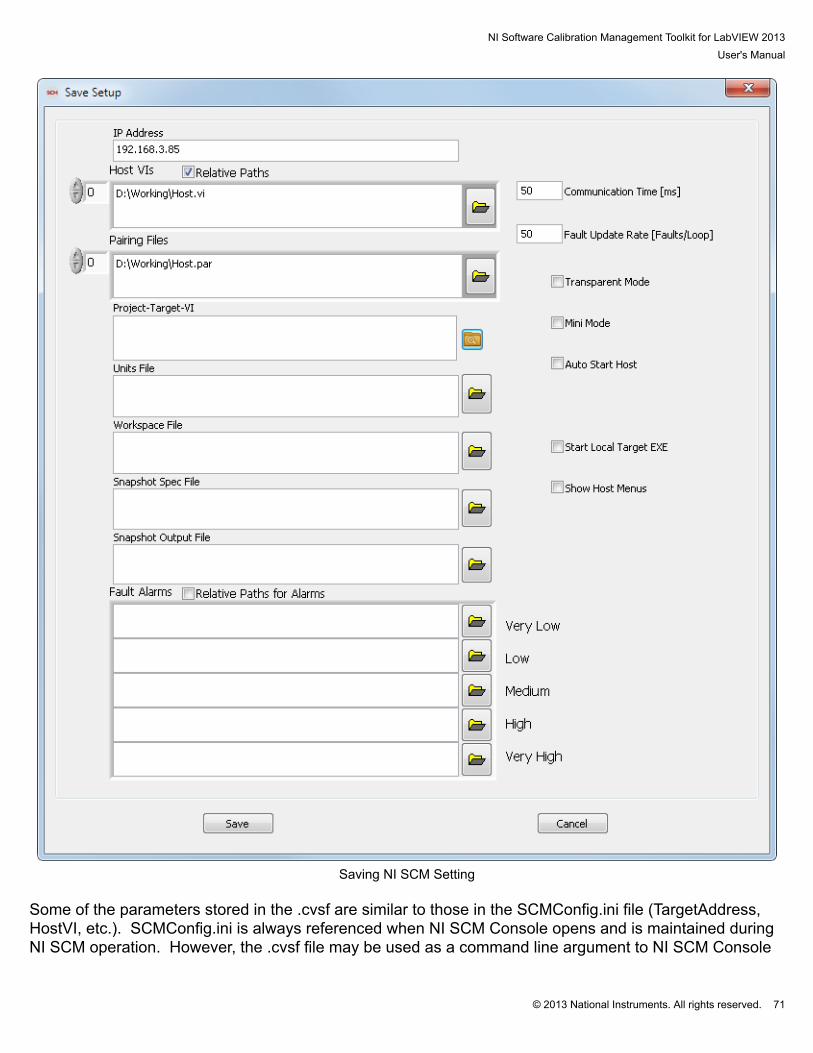
NI Software Calibration Management Toolkit for LabVIEW 2013User's Manual
© 2013 National Instruments. All rights reserved. 71
Saving NI SCM Setting
Some of the parameters stored in the .cvsf are similar to those in the SCMConfig.ini file (TargetAddress,HostVI, etc.). SCMConfig.ini is always referenced when NI SCM Console opens and is maintained duringNI SCM operation. However, the .cvsf file may be used as a command line argument to NI SCM Console

NI Software Calibration Management Toolkit for LabVIEW 2013User's Manual
© 2013 National Instruments. All rights reserved. 72
and the settings in the .cvsf file will override similar settings in SCMConfig.ini. This is useful for creatingdifferent .cvsf files for different projects so that a SCM environment may be loaded quickly. Furthermore,a .cvsf file will be associated with NI SCM Console by the NI SCM installer. Double clicking a .cvsf file or ashortcut to a .cvsf file will open NI SCM Console using the settings within the .cvsf file.
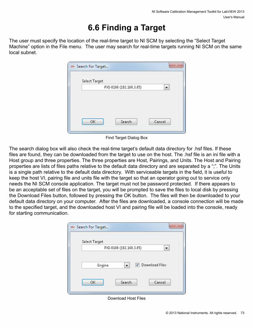
NI Software Calibration Management Toolkit for LabVIEW 2013User's Manual
© 2013 National Instruments. All rights reserved. 73
6.6 Finding a Target The user must specify the location of the real-time target to NI SCM by selecting the “Select TargetMachine” option in the File menu. The user may search for real-time targets running NI SCM on the samelocal subnet.
Find Target Dialog Box
The search dialog box will also check the real-time target’s default data directory for .hsf files. If thesefiles are found, they can be downloaded from the target to use on the host. The .hsf file is an ini file with aHost group and three properties. The three properties are Host, Pairings, and Units. The Host and Pairingproperties are lists of files paths relative to the default data directory and are separated by a “;”. The Unitsis a single path relative to the default data directory. With serviceable targets in the field, it is useful tokeep the host VI, pairing file and units file with the target so that an operator going out to service onlyneeds the NI SCM console application. The target must not be password protected. If there appears tobe an acceptable set of files on the target, you will be prompted to save the files to local disk by pressingthe Download Files button, followed by pressing the OK button. The files will then be downloaded to yourdefault data directory on your computer. After the files are downloaded, a console connection will be madeto the specified target, and the downloaded host VI and pairing file will be loaded into the console, readyfor starting communication.
Download Host Files
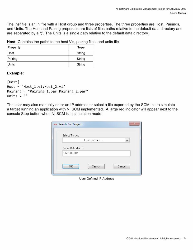
NI Software Calibration Management Toolkit for LabVIEW 2013User's Manual
© 2013 National Instruments. All rights reserved. 74
The .hsf file is an ini file with a Host group and three properties. The three properties are Host, Pairings,and Units. The Host and Pairing properties are lists of files paths relative to the default data directory andare separated by a “;”. The Units is a single path relative to the default data directory. Host: Contains the paths to the host Vis, pairing files, and units fileProperty Type
Host String
Pairing String
Units String Example: [Host]Host = "Host_1.vi;Host_2.vi"Pairing = "Pairing_1.par;Pairing_2.par"Units = "" The user may also manually enter an IP address or select a file exported by the SCM Init to simulatea target running an application with NI SCM implemented. A large red indicator will appear next to theconsole Stop button when NI SCM is in simulation mode.
User Defined IP Address
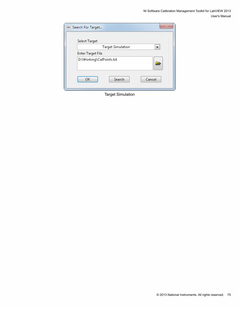
NI Software Calibration Management Toolkit for LabVIEW 2013User's Manual
© 2013 National Instruments. All rights reserved. 75
Target Simulation

NI Software Calibration Management Toolkit for LabVIEW 2013User's Manual
© 2013 National Instruments. All rights reserved. 76
6.7 Pairing CalPoints After the user has selected a host VI and a target, the NI SCM console program allows the user to pairhost controls and indicators to the CalPoints on the target. The user can drag items from the TargetItems list to the Host Items list as well as the reverse. The items can also be paired using the shortcutkeys defined by the SCMConfig.ini file. Errors will cause the Paired Items list to turn red and an X will bedisplayed by the item with an error. The message display area shows status messages. Problems readingfiles or connecting to the target will be displayed with orange highlight. The pairing must be made whilethe host VI is not running (communication is stopped).
NI Software Calibration Management Toolkit for LabVIEW 2013User's Manual
© 2013 National Instruments. All rights reserved. 77
6.8 Taking a Snapshot NI SCM has the ability to take a snapshot of the current values of specified host items (excluding tablesand arrays). The snapshot is stored in a TDMS file which is specified by the user. The data included inthe snapshot is defined by the log specifications file. The snapshot spec file is in the same format as thepairing file with the addition of a 5th column. The pairing file is a good starting point for creating a snapshotspec file. The 5th column defines the TDMS group which the data will be stored in. If no group is specified,the default group will be used. The same value may be placed in multiple groups but should not be placedin a group twice. If the same CalPoint is placed in the same group more than once, each snapshot willuse more than one TDMS line. The name of the CalPoint in the TDMS file will show up as the host name,using the host units. If a new CalPoint is introduced to a pre-existing TDMS output file, the TDMS file willbe back-filled with zeroes (for the new CalPoint) by NI SCM.

NI Software Calibration Management Toolkit for LabVIEW 2013User's Manual
© 2013 National Instruments. All rights reserved. 78
6.9 CalDiff (Calibration File Difference) CalDiff is a calibration file differencing utility that allows a user to easily compare and modify calibrationfiles. The utility opens two files specified at the top of each side of the tool. To load a file, enter the pathor use the browse button to find the file. The list of calibrations automatically updates when the pathchanges. The user may double click an item to push it to the other file. The user may also select one ormore items and use the right click menu options to manipulate the data.
Calibration File Differenceo Filter:# Differences Only: Only shows differences in the file# Type: Shows only the calibrations for a specified data type# Clear All: Clears all filter settingso Undo: Undo the last change, up to 10 changeso Exit: Closes the differencing tool
Saves the current data to the loaded filename
Saves the current data to a new file
Exports the current data to a TDMS file
Exports the current data to a CSV file
Reloads the current file

NI Software Calibration Management Toolkit for LabVIEW 2013User's Manual
© 2013 National Instruments. All rights reserved. 79
Opens the Calibration File Manager (displays and sets viewed files)
Closes the calibration differencing tool
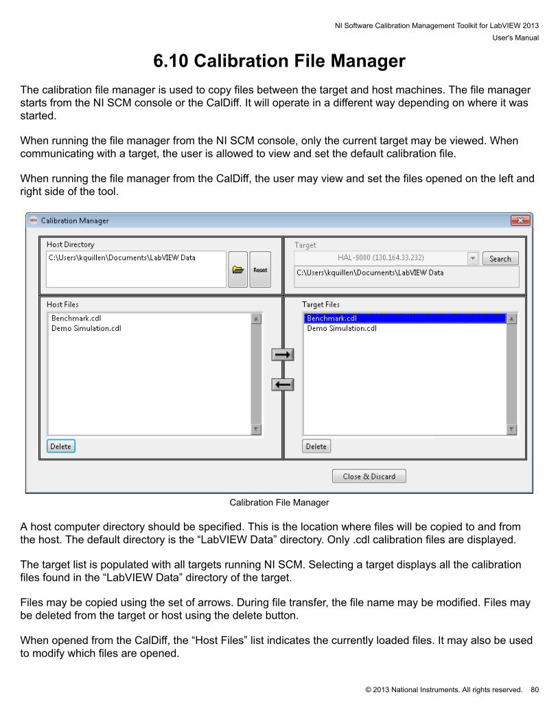
NI Software Calibration Management Toolkit for LabVIEW 2013User's Manual
© 2013 National Instruments. All rights reserved. 80
6.10 Calibration File Manager The calibration file manager is used to copy files between the target and host machines. The file managerstarts from the NI SCM console or the CalDiff. It will operate in a different way depending on where it wasstarted. When running the file manager from the NI SCM console, only the current target may be viewed. Whencommunicating with a target, the user is allowed to view and set the default calibration file. When running the file manager from the CalDiff, the user may view and set the files opened on the left andright side of the tool.
Calibration File Manager
A host computer directory should be specified. This is the location where files will be copied to and fromthe host. The default directory is the “LabVIEW Data” directory. Only .cdl calibration files are displayed. The target list is populated with all targets running NI SCM. Selecting a target displays all the calibrationfiles found in the “LabVIEW Data” directory of the target. Files may be copied using the set of arrows. During file transfer, the file name may be modified. Files maybe deleted from the target or host using the delete button. When opened from the CalDiff, the “Host Files” list indicates the currently loaded files. It may also be usedto modify which files are opened.

NI Software Calibration Management Toolkit for LabVIEW 2013User's Manual
© 2013 National Instruments. All rights reserved. 81
When opened from the NI SCM console while communicating with a target, the “Target File” indicates thecurrent calibration file on the target. It may also be used to change the current calibration file.

NI Software Calibration Management Toolkit for LabVIEW 2013User's Manual
© 2013 National Instruments. All rights reserved. 82
6.11 Unit Conversions Each CalPoint provides a field for specifying the engineering units of the parameter. In order to displaythe units along with the graphical controls or indicators on the host VI, the control’s caption must be madevisible in the editable version of the host VI with a minimal amount of text. The actual text within thecaption is not important because NI SCM will fill in the caption with the text provided with the CalPointunits field. The NI SCM console also provides a unit conversion utility so that the host VI can displaydifferent units than what are used on the target. The unit conversion utility allows the user to build aunits conversion file which provide conversion factors. NI SCM will convert the values to the requestedunits as they are transmitted to and from the target. The unit conversions are defined in the Unit Editordialog as shown in the figure below. NI SCM automatically converts the units based on the operator’spreferences. The units file has a .unt extension and is associated with a file of the same name havinga .duf extension describing the default units. National Instruments provides a sample units file found inthe NI SCM resources folder located at “c:\Program Files\National Instruments\SCM\Resources\Units.unt”.The Unit Editor summarizes all of the unit conversions in the units file and allows the user to open threedifferent dialogs for editing unit classes, unit conversions, and default units. A unit class describes acollection of associated unit conversions such as Pressure or Length. Complex units such as Speed area combination of base units and must have their own class. NI SCM will not combine units from differentclasses such as Length/Time. The “Save File” button commits the current configuration to the units file. The OK button saves the file and exits, whereas the Cancel button exits the unit editor without saving thefile.

NI Software Calibration Management Toolkit for LabVIEW 2013User's Manual
© 2013 National Instruments. All rights reserved. 83
Unit Editor The unit editor allows the user to add/remove unit conversions, add/remove unit classes, modify theunit conversions, and change the default display unit. Double clicking the first 2 columns opens a dialogbox to change the conversion factor of a unit conversion or edit the unit class name. Double clicking onthe default column changes the default unit of a unit class. The delete key removes the selected unitconversion or class. Double clicking the + in the add column adds a unit conversion to the unit class. The“New Unit Class” button adds a unit class. Each unit class and each unit conversion must be unique. Theconversion factors must be non-zero values. Errors are displayed with a red background.

NI Software Calibration Management Toolkit for LabVIEW 2013User's Manual
© 2013 National Instruments. All rights reserved. 84
Edit Unit Conversion
NI Software Calibration Management Toolkit for LabVIEW 2013User's Manual
© 2013 National Instruments. All rights reserved. 85
6.12 Unit Conversion Rules Unit conversions follow some simple rules.
• If host VI controls/indicators caption fields contain brackets, braces, or parentheses, then the units areenclosed in brackets, braces, or parentheses.
• If host VI controls/indicators caption fields contain “@”, then conversions are ignored.• If host VI controls/indicators caption fields contain “#”, then NI SCM converts to units specified after “#”
if the conversion exists. The default units will not be used.• Editable host VI must make caption visible with at least one character.• Unit file must be set and the Enable Unit Conversions must be checked under Options menu.

NI Software Calibration Management Toolkit for LabVIEW 2013User's Manual
© 2013 National Instruments. All rights reserved. 86
6.13 Example of Unit Conversions# Assumed Target Units: “psi”# Assumed Default Unit: “kPa”# … refers to any character
Editable Host VICaption Contains…
SCM Host VIDisplays…
Comments
… kPa Adds units
{…} {kPa} Leaves braces
[…] [kPa] Leaves brackets
(…) (kPa) Leaves parentheses
@... @psi Use target units (ignore defaultunits)
#Pa #Pa Use requested host units ifconversion exists
#ft kPa Use default host units if noconversion exists
[@atm] [@psi] Combination
{#atm} {#atm} Combination
psi|in|sec kPa|in|sec Multiple Units (Tables)

NI Software Calibration Management Toolkit for LabVIEW 2013User's Manual
© 2013 National Instruments. All rights reserved. 87
7. Simple Example

NI Software Calibration Management Toolkit for LabVIEW 2013User's Manual
© 2013 National Instruments. All rights reserved. 88
7.1 Basic Project ExampleA NI LabVIEW project which implements NI SCM should contain a real-time target with a real-time VI asshown in the figure below. The following example project is included in the Installer and can be found inthe NI Example Finder.
Example Project
The top level real-time VI should contain four main parts as shown in the figure below. 1. SCM Init VI: Loads calibration file and initializes NI SCM2. Case Structure: Prevents loops from running if initialization error occurs.3. Loop(s) Containing CalPoint(s): CalPoints may exist in SubVIs. SubVIs with CalPoints must beadded to the project under the real-time target. Creating a project folder such as “RTSubVI” for collectingsubVIs is recommended.

NI Software Calibration Management Toolkit for LabVIEW 2013User's Manual
© 2013 National Instruments. All rights reserved. 89
Basic NI SCM Project Example Real-Time VI
NI Software Calibration Management Toolkit for LabVIEW 2013User's Manual
© 2013 National Instruments. All rights reserved. 90
8. TroubleshootingA Microsoft Windows Help file (.chm) for NI SCM Software is provided with the software download. The file and beopened using the start menu. Frequently Asked Questions (FAQs)
Q: Why are some CalPoints not found by SCM Init? A: All VIs containing CalPoints must be included in the project under the target.
A: CalPoints in disable diagram structures will not be found by SCM Init.
Q: Why are CalPoints behaving unexpectedly?
A: SCM Init VI Configuration Dialog must be opened before deploying in order to build CalPoint table for run-time.
A: The target VI must be started from a LabVIEW project.
A: Limits and slew rates for U32 and I32 CalPoints are represented internally as float32. Because of this not all 32bit numbers are available, especially those that cannot be represented in less than 24 bits.
Q: What are some restrictions for CalPoint Name? A: A “.” (period) is not allowed in any part of a CalPoint name. A: A “|” (pipe) is used as the separator for CalPoint Class|Group|Name and units. It should not be used withinthese individual fields of the configuration dialog. Q: Why is LabVIEW unable to find some VIs while opening a NI SCM target VI?
A: Open and close the SCM Init VI to update it to the latest version. A: When opening a VI under the “My Computer” target, some real time libraries are unavailable and should beignored (“RT Set Date and Time.vi”). Ignoring the VIs should not cause errors. Q: Why does deploying NI SCM project to a real-time target fail? A: Some targets require software to be installed before deploying. Use Measurements and Automation Explorer toinstall the NI SCM components. Q: What are the requirements for a host VI? A: Host VI must contain a while loop and a wait. A: Host control/indicator names cannot contain carriage return. A: Host control/indicator names must be unique.

NI Software Calibration Management Toolkit for LabVIEW 2013User's Manual
© 2013 National Instruments. All rights reserved. 91
A: An enumerated item on the host VI must have the same number of enumerated items as the CalPoint. Thestring for each enumerated item on the host does not matter because the Text Labels from the target CalPoint will becopied over.
Q: Why does the Host VI open but does not run? A: The broken run arrow will show a list of errors. If subVIs are missing, locate them so that the host VI can run. A: Some errors require opening the Host VI in the NI LabVIEW to fix the error. The broken arrow in the full versionof NI LabVIEW will give details about the errors. Q: Why am I having trouble pairing two items? A: The NI SCM console will only allow pairings for target and host items having the same data type and samedirection (control or indicator). A: Host Boolean controls must be set to switching mechanical action. A: Host control/indicator names cannot contain carriage return. A: Host control/indicator names must be unique. Q: Why does the NI SCM Console not find my target? A: NI SCM Console will only find targets running a NI SCM based project. A: NI SCM Console can only find targets on the same subnet as the host computer. A: TCP/IP and UDP ports may need to be unblocked in hardware and software firewalls to allow NI SCM to findtargets or transfer files. The list of used ports is listed above. A: NI SCM may not find the host VI and pairing files stored on the target due to some networks or host computerswith security software installed. A: NI SCM may not connect to the target if the target application was not started from a LabVIEW project. Afteropening the target VI from the project, run the SCM Init. Q: Why does the NI SCM Console not find my Host VI? A: Check the file path to the VI. A: Check the version of the VI. If the VI was last saved using an incompatible version of NI LabVIEW, open it inthe compatible version of NI LabVIEW and try again. Save for previous version will not work. A: NI SCM may not load a host VI if it contains a Waveform Graph with certain types of inputs such as clusters.Instead, wire an array directly to the Waveform Graph. Q: Why is the host and target time off by X hours after setting the target time?
NI Software Calibration Management Toolkit for LabVIEW 2013User's Manual
© 2013 National Instruments. All rights reserved. 92
A: The target and host times are set using the universal time stamp. If the target time zone is different than thehost time zone, the two will have local times that are off by the appropriate number of hours. Set the target time zoneusing the measurements and automation explorer. Q: What can I do to run NI SCM over a slow connection? A: CalScopes and large arrays take large amounts of bandwidth. Limit their use. A: Set the communication loop time (via the NI SCM Console) to a slower speed. Q: Can I revert my project to CalVIEW? A: NI SCM projects cannot be reverted to CalVIEW automatically. CalPoints need to be deleted and recreatedusing CalVIEW. A: The NI SCM will update all CalPoints but there is no reverse for the process. A: The CalVIEW console should work with a target built with NI SCM. A: The NI SCM console should work with a target built with CalVIEW.

NI Software Calibration Management Toolkit for LabVIEW 2013User's Manual
© 2013 National Instruments. All rights reserved. 93
9. Additional Support/Feedback Please contact NI Systems Support at 210-248-9308 or [email protected]. For additional help with getting your NI hardware and software installed and configured, visit: http://www.ni.com/gettingstarted/

NI Software Calibration Management Toolkit for LabVIEW 2013User's Manual
© 2013 National Instruments. All rights reserved. 94
10. Important Information

NI Software Calibration Management Toolkit for LabVIEW 2013User's Manual
© 2013 National Instruments. All rights reserved. 95
10.1 WarrantyRemove the following paragraph for software products. NI SCM Software is warranted against defects in materials and workmanship for a period of one year from the dateof shipment, as evidenced by receipts or other documentation. National Instruments will, at its option, repair orreplace equipment that proves to be defective during the warranty period. This warranty includes parts and labor. The media on which you receive National Instruments software are warranted not to fail to execute programminginstructions, due to defects in materials and workmanship, for a period of 90 days from date of shipment, asevidenced by receipts or other documentation. National Instruments will, at its option, repair or replace softwaremedia that do not execute programming instructions if National Instruments receives notice of such defects duringthe warranty period. National Instruments does not warrant that the operation of the software shall be uninterruptedor error free. A Return Material Authorization (RMA) number must be obtained from the factory and clearly marked on the outsideof the package before any equipment will be accepted for warranty work. National Instruments will pay the shippingcosts of returning to the owner parts which are covered by warranty. National Instruments believes that the information in this document is accurate. The document has been carefullyreviewed for technical accuracy. In the event that technical or typographical errors exist, National Instrumentsreserves the right to make changes to subsequent editions of this document without prior notice to holders ofthis edition. The reader should consult National Instruments if errors are suspected. In no event shall NationalInstruments be liable for any damages arising out of or related to this document or the information contained in it. EXCEPT AS SPECIFIED HEREIN, NATIONAL INSTRUMENTS MAKES NO WARRANTIES, EXPRESSOR IMPLIED, AND SPECIFICALLY DISCLAIMS ANY WARRANTY OF MERCHANTABILITY OR FITNESSFOR A PARTICULAR PURPOSE. CUSTOMER'S RIGHT TO RECOVER DAMAGES CAUSED BY FAULTOR NEGLIGENCE ON THE PART OF NATIONAL INSTRUMENTS SHALL BE LIMITED TO THE AMOUNTTHERETOFORE PAID BY THE CUSTOMER. NATIONAL INSTRUMENTS WILL NOT BE LIABLE FOR DAMAGESRESULTING FROM LOSS OF DATA, PROFITS, USE OF PRODUCTS, OR INCIDENTAL OR CONSEQUENTIALDAMAGES, EVEN IF ADVISED OF THE POSSIBILITY THEREOF. This limitation of the liability of NationalInstruments will apply regardless of the form of action, whether in contract or tort, including negligence. Any actionagainst National Instruments must be brought within one year after the cause of action accrues. National Instrumentsshall not be liable for any delay in performance due to causes beyond its reasonable control. The warranty providedherein does not cover damages, defects, malfunctions, or service failures caused by owner's failure to follow theNational Instruments installation, operation, or maintenance instructions; owner's modification of the product; owner'sabuse, misuse, or negligent acts; and power failure or surges, fire, flood, accident, actions of third parties, or otherevents outside reasonable control.

NI Software Calibration Management Toolkit for LabVIEW 2013User's Manual
© 2013 National Instruments. All rights reserved. 96
10.2 CopyrightUnder the copyright laws, this publication may not be reproduced or transmitted in any form, electronic ormechanical, including photocopying, recording, storing in an information retrieval system, or translating, in whole orin part, without the prior written consent of National Instruments Corporation. National Instruments respects the intellectual property of others, and we ask our users to do the same. NI software isprotected by copyright and other intellectual property laws. Where NI software may be used to reproduce software orother materials belonging to others, you may use NI software only to reproduce materials that you may reproduce inaccordance with the terms of any applicable license or other legal restriction.End-User License Agreements and Third-Party Legal Notices You can find end-user license agreements (EULAs) and third-party legal notices in the following locations: Notices are located in the <National Instruments>\_Legal Information and <National Instruments> directories. EULAs are located in the <National Instruments>\Shared\MDF\Legal\license directory. Review <National Instruments>\_Legal Information.txt for information on including legal information in installersbuilt with NI products.
NI Software Calibration Management Toolkit for LabVIEW 2013User's Manual
© 2013 National Instruments. All rights reserved. 97
10.3 TrademarksRefer to the NI Trademarks and Logo Guidelines at ni.com/trademarks for more information on National Instrumentstrademarks. ARM, Keil, and µVision are trademarks or registered of ARM Ltd or its subsidiaries. LEGO, the LEGO logo, WEDO, and MINDSTORMS are trademarks of the LEGO Group. ©2013 The LEGO Group. TETRIX by Pitsco is a trademark of Pitsco, Inc. ©2013. FIELDBUS FOUNDATION™ and FOUNDATION™ are trademarks of the Fieldbus Foundation. EtherCAT® is a registered trademark of and licensed by Beckhoff Automation GmbH. CANopen® is a registered Community Trademark of CAN in Automation e.V. DeviceNet™ and EtherNet/IP™ are trademarks of ODVA. Go!, SensorDAQ, and Vernier are registered trademarks of Vernier Software & Technology. Vernier Software &Technology and vernier.com are trademarks or trade dress. Xilinx is the registered trademark of Xilinx, Inc. Taptite and Trilobular are registered trademarks of Research Engineering & Manufacturing Inc. FireWire® is the registered trademark of Apple Inc. Linux® is the registered trademark of Linus Torvalds in the U.S. and other countries. Handle Graphics®, MATLAB®, Real-Time Workshop®, Simulink®, Stateflow®, and xPC TargetBox® are registeredtrademarks, and TargetBox™ and Target Language Compiler™ are trademarks of The MathWorks, Inc. Tektronix®, Tek, and Tektronix, Enabling Technology are registered trademarks of Tektronix, Inc. The Bluetooth® word mark is a registered trademark owned by the Bluetooth SIG, Inc. The ExpressCard™ word mark and logos are owned by PCMCIA and any use of such marks by NationalInstruments is under license. The mark LabWindows is used under a license from Microsoft Corporation. Windows is a registered trademark ofMicrosoft Corporation in the United States and other countries. Other product and company names mentioned herein are trademarks or trade names of their respective companies. Members of the National Instruments Alliance Partner Program are business entities independent from NationalInstruments and have no agency, partnership, or joint-venture relationship with National Instruments.

NI Software Calibration Management Toolkit for LabVIEW 2013User's Manual
© 2013 National Instruments. All rights reserved. 98
10.4 PatentsFor patents covering the National Instruments products/technology, refer to the appropriate location: Help»Patents inyour software, the patents.txt file on your media, or the National Instruments Patent Notice at ni.com/patents.
NI Software Calibration Management Toolkit for LabVIEW 2013User's Manual
© 2013 National Instruments. All rights reserved. 99
10.5 Warning Regarding Use of NI ProductsWARNING REGARDING USE OF NATIONAL INSTRUMENTS PRODUCTS (1) NATIONAL INSTRUMENTS PRODUCTS ARE NOT DESIGNED WITH COMPONENTS AND TESTING FORA LEVEL OF RELIABILITY SUITABLE FOR USE IN OR IN CONNECTION WITH SURGICAL IMPLANTS ORAS CRITICAL COMPONENTS IN ANY LIFE SUPPORT SYSTEMS WHOSE FAILURE TO PERFORM CANREASONABLY BE EXPECTED TO CAUSE SIGNIFICANT INJURY TO A HUMAN. (2) IN ANY APPLICATION, INCLUDING THE ABOVE, RELIABILITY OF OPERATION OF THE SOFTWAREPRODUCTS CAN BE IMPAIRED BY ADVERSE FACTORS, INCLUDING BUT NOT LIMITED TO FLUCTUATIONSIN ELECTRICAL POWER SUPPLY, COMPUTER HARDWARE MALFUNCTIONS, COMPUTER OPERATINGSYSTEM SOFTWARE FITNESS, FITNESS OF COMPILERS AND DEVELOPMENT SOFTWARE USED TODEVELOP AN APPLICATION, INSTALLATION ERRORS, SOFTWARE AND HARDWARE COMPATIBILITYPROBLEMS, MALFUNCTIONS OR FAILURES OF ELECTRONIC MONITORING OR CONTROL DEVICES,TRANSIENT FAILURES OF ELECTRONIC SYSTEMS (HARDWARE AND/OR SOFTWARE), UNANTICIPATEDUSES OR MISUSES, OR ERRORS ON THE PART OF THE USER OR APPLICATIONS DESIGNER (ADVERSEFACTORS SUCH AS THESE ARE HEREAFTER COLLECTIVELY TERMED "SYSTEM FAILURES"). ANYAPPLICATION WHERE A SYSTEM FAILURE WOULD CREATE A RISK OF HARM TO PROPERTY OR PERSONS(INCLUDING THE RISK OF BODILY INJURY AND DEATH) SHOULD NOT BE RELIANT SOLELY UPON ONEFORM OF ELECTRONIC SYSTEM DUE TO THE RISK OF SYSTEM FAILURE. TO AVOID DAMAGE, INJURY,OR DEATH, THE USER OR APPLICATION DESIGNER MUST TAKE REASONABLY PRUDENT STEPS TOPROTECT AGAINST SYSTEM FAILURES, INCLUDING BUT NOT LIMITED TO BACK-UP OR SHUT DOWNMECHANISMS. BECAUSE EACH END-USER SYSTEM IS CUSTOMIZED AND DIFFERS FROM NATIONALINSTRUMENTS' TESTING PLATFORMS AND BECAUSE A USER OR APPLICATION DESIGNER MAY USENATIONAL INSTRUMENTS PRODUCTS IN COMBINATION WITH OTHER PRODUCTS IN A MANNER NOTEVALUATED OR CONTEMPLATED BY NATIONAL INSTRUMENTS, THE USER OR APPLICATION DESIGNERIS ULTIMATELY RESPONSIBLE FOR VERIFYING AND VALIDATING THE SUITABILITY OF NATIONALINSTRUMENTS PRODUCTS WHENEVER NATIONAL INSTRUMENTS PRODUCTS ARE INCORPORATED IN ASYSTEM OR APPLICATION, INCLUDING, WITHOUT LIMITATION, THE APPROPRIATE DESIGN, PROCESS ANDSAFETY LEVEL OF SUCH SYSTEM OR APPLICATION.

NI Software Calibration Management Toolkit for LabVIEW 2013User's Manual
© 2013 National Instruments. All rights reserved. 100
10.6 Environmental ManagementNational Instruments is committed to designing and manufacturing products in an environmentally responsiblemanner. NI recognizes that eliminating certain hazardous substances from our products is beneficial not only to theenvironment but also to NI customers. For additional environmental information, refer to the NI and the Environment Web page at ni.com/environment. Thispage contains the environmental regulations and directives with which NI complies, as well as other environmentalinformation not included in this document.


![Pediatric Gait Trainer using LabVIEW VI and Arduino - …ijetch.org/vol7/846-W042.pdf · From LabVIEW VI to Arduino Sketch ... LabVIEW Interface For Arduino toolkit or LIFA [8] is](https://static.fdocuments.us/doc/165x107/5bb52d4c09d3f2213f8b8faa/pediatric-gait-trainer-using-labview-vi-and-arduino-from-labview-vi-to-arduino.jpg)