Robotics. Why Robotics? Practice Promise Why Robotics? Vibrant field.

USER MANUAL
NI roboRIORIO Device for Robotics
The NI roboRIO is a portable reconfigurable I/O (RIO) device that is used to design control,robotics, and mechatronics systems.
This document contains pinouts, connectivity information, dimensions, and mountinginstructions for the NI roboRIO. The NI roboRIO provides the I/O shown in the followingfigure and connects to a host computer over USB and 10/100 Ethernet.
Figure 1. NI roboRIO Features
NI roboRIONI roboRIO
POWERPOWER
STATUSSTATUS
RADIORADIOSPISPI
CS0CS0CS1CS15V5VCS2CS2CS3CS3
SCLKSCLKMOSIMOSI
INPUTINPUT
CANCAN
7-16V7-16V45W MAX45W MAX
L (GRN)L (GRN)
H (YEL)H (YEL)
II22CC
SCLSCL
3.3V SDA3.3V SDA
RS-232RS-232
TXDTXDRXDRXD
RSLRSL
MISOMISO3.3V3.3V
COMMCOMM
MODEMODE
RSLRSL
RELAYRELAY00 11
FWDFWD5V5V
SS
SS REVREV
22 33 00 11
113333
22 33
3322
1100
7799
8866
554444
5566
7788
9900
1122
33
ANALOG INANALOG IN RESETRESET
ACCELEROMETERACCELEROMETER
PWM
PWMD
IOD
IO
YY
ZZXX
USERUSER
SS5V5V
SS6V6V
5 6 7 8
14
9 10
15161718
121
2
3
4
13
11
1. Digital input and output (DIO) port2. RS-232 port3. I2C port4. CAN port5. Power connector6. USB Device port7. USB Host retention mount8. USB Host ports9. Ethernet port
10. Serial peripheral interface bus (SPI) port11. LEDs12. Pulse-width modulation (PWM) port13. myRIO Expansion Port (MXP)14. MXP retention mount15. User and Reset buttons16. Analog input (AI) port17. Relay port18. Robot signal light (RSL) port

ContentsSafety Information.................................................................................................................... 3Electromagnetic Compatibility Guidelines...............................................................................3Hardware Block Diagram......................................................................................................... 3Setting Up the NI roboRIO....................................................................................................... 4
Connecting to Power.........................................................................................................4Powering On the Device................................................................................................... 5Connecting to a Network.................................................................................................. 5User Power........................................................................................................................6Input Voltage Brownout Behavior.................................................................................... 6
Pinouts.......................................................................................................................................7MXP.................................................................................................................................. 8CAN Port...........................................................................................................................9I2C Port..............................................................................................................................9RS-232 Port.....................................................................................................................10DIO Port..........................................................................................................................10RSL Port..........................................................................................................................11Relay Port........................................................................................................................11AI Port.............................................................................................................................12PWM Port....................................................................................................................... 12SPI Port........................................................................................................................... 13
Signal Ground References...................................................................................................... 13Interfaces.................................................................................................................................14
AI Channels.....................................................................................................................14AO Channels................................................................................................................... 14DIO, PWM, and Relay Lines.......................................................................................... 15UART and RS-232 Lines................................................................................................ 16SPI Lines......................................................................................................................... 16I2C Lines......................................................................................................................... 16USB Device Port.............................................................................................................16USB Host Port.................................................................................................................16
Accelerometer......................................................................................................................... 16Converting Raw Data Values to Voltage.................................................................................17Front Panel Buttons.................................................................................................................17
Reset Button....................................................................................................................17User Button..................................................................................................................... 18
LED Indications...................................................................................................................... 18Power LED......................................................................................................................18Status LED...................................................................................................................... 18Radio LED...................................................................................................................... 19Comm LED..................................................................................................................... 19Mode LED.......................................................................................................................20RSL (Safety) LED...........................................................................................................20
Physical Dimensions............................................................................................................... 21
2 | ni.com | NI roboRIO User Manual

Mounting the NI roboRIO.......................................................................................................24Method One: Using Cable Ties to Secure One Edge of the NI roboRIO to
Perfboard...................................................................................................................24Method Two: Using Cable Ties to Secure One Corner of the NI roboRIO to
Perfboard...................................................................................................................26Method Three: Using Screws to Secure the Bottom of the NI roboRIO to a Metal
Plate.......................................................................................................................... 29Compatible USB and Ethernet Cables.................................................................................... 29Warranty..................................................................................................................................30Worldwide Support and Services............................................................................................ 30
Safety InformationCaution Do not operate the roboRIO in a manner not specified in this document.Product misuse can result in a hazard. You can compromise the safety protectionbuilt into the product if the product is damaged in any way. If the product isdamaged, return it to NI for repair.
Clean the product with a soft, nonmetallic brush. Make sure that the product is completely dryand free from contaminants before returning it to service.
Electromagnetic Compatibility GuidelinesThis product was tested and complies with the regulatory requirements and limits forelectromagnetic compatibility (EMC) stated in the product specifications. These requirementsand limits provide reasonable protection against harmful interference when the product isoperated in the intended operational electromagnetic environment.
This product is intended for use in industrial locations. However, harmful interference mayoccur in some installations, when the product is connected to a peripheral device or test object,or if the product is used in residential or commercial areas. To minimize interference withradio and television reception and prevent unacceptable performance degradation, install anduse this product in strict accordance with the instructions in the product documentation.
Furthermore, any changes or modifications to the product not expressly approved by NationalInstruments could void your authority to operate it under your local regulatory rules.
Hardware Block DiagramThe following figure shows the arrangement and functions of NI roboRIO components.
NI roboRIO User Manual | © National Instruments | 3

Figure 2. NI roboRIO Hardware Block Diagram
CANPort
Xilinx Zynq-7020
Processor/FPGA(LabVIEW RT)
USB Device
Port
USB HostPorts
10/100 Ethernet
Port
Status LED
Comm LED
Radio LED
Mode LED
RSL LED
Power LED
+3.3 V
+5.0 V
16 16
2
4
UART
DIO
Analog Out
Analog In
myRIOExpansionPort (MXP)
UserButton
ResetButton
PWMPort1010
+6.0 V
PWM
SPI
SPI Port
+5.0 V+3.3 V
7
72
RS-232RS-232Port
2
I2C
I2CPort 2
+3.3 V
DIOPort
DIO10 10
+5.0 V
Watchdog
NonvolatileMemory
DDR3
Acceler-ometer
RSL
RSLPort
Relay
8
8
RELAYPort
4
+5.0 VAI
ANALOG INPort
Setting Up the NI roboRIO
Connecting to PowerThe NI roboRIO requires an external power supply that meets the specifications in the PowerRequirements section of the NI roboRIO Specifications. The NI roboRIO filters and regulatesthe supplied power and provides power for all of the I/O and user voltage. The NI roboRIOhas one layer of reverse-voltage protection.
Complete the following steps to connect a power supply to the chassis.1. Ensure that the power supply is turned off.
4 | ni.com | NI roboRIO User Manual
Caution Do not install or remove the power connector from the front panel ofthe NI roboRIO while power is applied.
2. Connect the positive lead of the power supply to the V terminal of the COMBICONpower connector shipped with the NI roboRIO, and tighten the terminal screw. Thefollowing figure shows the terminal screws, which secure the wires in the screwterminals, and the connector screws, which secure the power connector on the front panel.
Figure 3. NI roboRIO COMBICON Power Connector
CV
2
2
1
1. Terminal Screws2. Connector Screws
3. Connect the negative lead of the power supply to the C terminal of the power connectorand tighten the terminal screw.
4. Install the power connector on the front panel of the NI roboRIO and tighten theconnector screws.
5. Turn on the power supply.
Powering On the DeviceThe NI roboRIO runs a power-on self test (POST) when you apply power to the device.During the POST, the Power and Status LEDs turn on. When the Status LED turns off, thePOST is complete. If the LEDs do not behave in this way when the system powers on, refer tothe LED Indications section.
Connecting to a NetworkConnect the NI roboRIO to an Ethernet network using the Ethernet port. Use a standardCategory 5 (CAT-5) or better shielded, twisted-pair Ethernet cable to connect the NI roboRIOto an Ethernet hub, router, or directly to a computer.
Caution To prevent data loss and to maintain the integrity of your Ethernetinstallation, do not use a cable longer than 30 m.
The first time you power up the chassis, it attempts to initiate a DHCP network connection. Ifthe chassis is unable to initiate a DHCP connection, it connects to the network with a link-local IP address with the form 169.254.x.x.
NI roboRIO User Manual | © National Instruments | 5

User PowerThe following table describes the user voltage rails for powering external sensors andperipherals. The rails are independent from the power supplies of internal systems, such as theprocessor and memory.
Table 1. NI roboRIO Voltage Rails
Voltage Rail Description
+6 V Power from PWM ports for use with servos.
+5 V Power for DIO and AI ports for sensors, and power for the MXP for poweringexpansion circuits.
+3.3 V Power for I2C, SPI, and the MXP.
Input Voltage Brownout BehaviorThe NI roboRIO input voltage range is 7 V to 16 V. The input voltage monitoring circuitmonitors the voltage on the input voltage pin. When the input voltage drops to between 4.5 V
6 | ni.com | NI roboRIO User Manual

and 6.8 V, the NI roboRIO enters brownout mode with a staged response, as the followingtable describes.
Table 2. NI roboRIO Input Voltage Brownout Behavior
StageInput Voltage
RangeBehavior
1 6.3 V to 6.8 V The +6 V voltage rail starts to drop.
2 4.5 V to 6.3 V
The NI roboRIO enters a brownout fault condition and thefollowing precautions are taken:• User voltage rails become disabled.• All PWM generation stops at the conclusion of the current
cycle.• GPIOs configured as outputs go to High-Z.• Relay control outputs are driven low.• CAN-based motor controllers become disabled.
The following systems continue to function normally with validdata and communication:• FPGA, processor, RAM, disk, and user code• USB power and communication• Radio, if powered by USB• Ethernet• CAN• AI and AO• I2C• SPI• RS-232 serial• LED and RSL status lights
Stage 2 continues until the input voltage rises to greater than 7.5 Vor drops to less than 4.5 V.
3 Less than 4.5 V
All controller functions cease and the controller state is lost. Thiscondition continues until the input voltage rises to greater than4.65 V, at which point the controller starts the normal bootingsequence. At startup, the controller remains in Stage 2 until theinput voltage rises to greater than 7.5 V.
PinoutsThe following describe the pins and signals on the NI roboRIO ports.
NI roboRIO User Manual | © National Instruments | 7
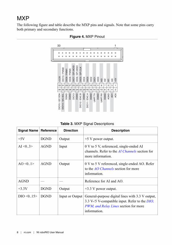
MXPThe following figure and table describe the MXP pins and signals. Note that some pins carryboth primary and secondary functions.
Figure 4. MXP Pinout
AO
0
AO
1
AG
ND
DG
ND
UA
RT.
RX
DG
ND
UA
RT.
TX
DG
ND
DIO
11 /
EN
C.A
DG
ND
DIO
12 /
EN
C.B
DG
ND
DIO
13
DG
ND
DG
ND
DIO
14 /
I2C
.SC
L
DIO
15 /
I2C
. SD
A
+5V
AI1
AI3
AI2
DIO
1
DIO
2
DIO
3
DIO
4
AI0
DIO
0
DIO
5 / S
PI.C
LK
DIO
6 / S
PI.M
ISO
DIO
7 / S
PI.M
OS
I
DIO
8 / P
WM
0
DIO
9 / P
WM
1
DIO
10 /
PW
M2
+3.
3V
34
33
32
31
30
29
28
27
26
25
24
23
22
21
20
19
18
17
16
15
14
13
12
11
10
9
8
7
6
5
4
3
2
1
133
Table 3. MXP Signal Descriptions
Signal Name Reference Direction Description
+5V DGND Output +5 V power output.
AI <0..3> AGND Input 0 V to 5 V, referenced, single-ended AIchannels. Refer to the AI Channels section formore information.
AO <0..1> AGND Output 0 V to 5 V referenced, single-ended AO. Referto the AO Channels section for moreinformation.
AGND — — Reference for AI and AO.
+3.3V DGND Output +3.3 V power output.
DIO <0..15> DGND Input or Output General-purpose digital lines with 3.3 V output,3.3 V-/5 V-compatible input. Refer to the DIO,PWM, and Relay Lines section for moreinformation.
8 | ni.com | NI roboRIO User Manual

Table 3. MXP Signal Descriptions (Continued)
Signal Name Reference Direction Description
UART.RX DGND Input UART receive input. UART lines areelectrically identical to DIO lines.
UART.TX DGND Output UART transmit output. UART lines areelectrically identical to DIO lines.
DGND — — Reference for digital signals, +5 V, and +3.3 V.
CAN PortThe following figure and table describe the CAN port pins and signals.
Figure 5. CAN Port Pinout
H (YEL)
L (GRN)
Table 4. CAN Port Signal Descriptions
Signal Name Direction Description
L (GRN) Input/Output CAN bus differential low signal.
H (YEL) Input/Output CAN bus differential high signal.
Note The NI roboRIO contains an internal 120 Ω termination resistor between L(GRN) and H (YEL).
I2C PortThe following figure and table describe the I2C port pins and signals.
Figure 6. I2C Port Pinout
3.3V
SCL
SDA
NI roboRIO User Manual | © National Instruments | 9

Table 5. I2C Port Signal Descriptions
Signal Name Direction Description
GND — Reference for digital lines and +3.3 V power output.
3.3V Output +3.3 V power output.
SCL Input or Output I2C lines with 3.3 V output, 3.3 V-/5 V-compatible input.Refer to the I2C Lines section for more information.
SDA Input or Output
RS-232 PortThe following figure and table describe the RS-232 port pins and signals.
Figure 7. RS-232 Serial Port Pinout
RXDTXD
Table 6. RS-232 Serial Port Signal Descriptions
Signal Name Direction Description
TXD Output Serial transmit output with ±5 V to ±15 V signal levels. Refer tothe UART and RS-232 Lines section for more information.
RXD Input Serial receive input with ±15 V input voltage range. Refer to the UART and RS-232 Lines section for more information.
GND — Reference for digital lines.
DIO PortThe following figure and table describe the DIO port pins and signals.
Figure 8. DIO Port Pinout
1 2 3 5 6 74 80 9
S5V
10 | ni.com | NI roboRIO User Manual

Table 7. DIO Port Signal Descriptions
Signal Name Direction Description
S (DIO) <0..9> Input/Output General-purpose digital lines with 3.3 V output, 3.3 V-/5 V-compatible input. Refer to the DIO, PWM, and Relay Linessection for more information.
5V Output +5 V power output.
GND — Reference for digital lines and +5 V power output.
RSL PortThe following figure and table describe the RSL port pins and signals.
Figure 9. RSL Port Pinout
S
Table 8. RSL Port Signal Descriptions
Signal Name Direction Description
S Output Switched power output to drive RSL when RSL is enabled. Thevoltage level depends on the connected input voltage. RSL currentis limited at 120 mA.
GND — Reference for S.
Relay PortThe following figure and table describe the Relay port pins and signals.
Figure 10. Relay Port Pinout
1 2FWDREV
30
NI roboRIO User Manual | © National Instruments | 11

Table 9. Relay Port Signal Descriptions
Signal Name Direction Description
FWD <0..3> Output Relay digital lines with 5 V output.
REV <0..3> Output Relay digital lines with 5 V output.
GND — Reference for digital lines.
AI PortThe following figure and table describe the AI port pins and signals.
Figure 11. AI Port Pinout
S5V
1 20 3
Table 10. AI Port Signal Descriptions
Signal Name Direction Description
S (AI) <0..3> Input 0 V to 5 V referenced, single-ended AI channels. Refer to the AIChannels section for more information.
5V Output +5 V power output.
GND — Reference for AI and +5 V power.
PWM PortThe following figure and table describe the PWM port pins and signals.
Figure 12. PWM Port Pinout
8 7 6 4 3 25 19 0
S6V
12 | ni.com | NI roboRIO User Manual

Table 11. PWM Port Signal Descriptions
Signal Name Direction Description
S (PWM) <0..9> Output PWM digital lines with 5 V output.
6V Output +6 V power output for servos only.
GND — Reference for digital lines and +6 V power output.
SPI PortThe following figure and table describe the SPI port pins and signals.
Figure 13. SPI Port Pinout
SCLKMOSIMISO
3.3V
CS0CS1
CS2CS3
5V
Table 12. SPI Port Signal Descriptions
Signal Name Direction Description
3.3V Output +3.3 V power output.
5V Output +5 V power output.
CS <0..3> Output SPI with 3.3 V output, 3.3 V-/5 V-compatible input. Refer to the SPI Lines section for more information.
SCLK Output
MOSI Output
MISO Input
GND — Reference for digital lines and +3.3 V and +5.5 V power output.
Signal Ground ReferencesTo minimize noise on analog measurement channels, use the ground reference of thecorresponding port. For example, when you are using AI, the measurement should referencethe GND of the AI port.
NI roboRIO User Manual | © National Instruments | 13

Interfaces
AI ChannelsThe NI roboRIO has AI channels on the MXP and on the AI port. The channels aremultiplexed to a single analog-to-digital converter (ADC) that samples all channels.
The MXP and the AI port each has four single-ended AI channels, AI0-AI3, which you canuse to measure 0 V to 5 V signals.
Note For important information about improving measurement accuracy byreducing noise, visit ni.com/info and enter the Info Code analogwiring.
The following figure shows the AI topology of the NI roboRIO.
Figure 14. NI roboRIO AI Circuitry
MUX ADC
AI0AI1AI2AI3
AI0AI1AI2AI3
0–5 V
Expansion port (MXP)
Integrated AI port
AO ChannelsThe NI roboRIO MXP has two AO channels, AO0 and AO1, which you can use to generatesignals of 0 V to 5 V. Each channel has a dedicated digital-to-analog converter (DAC), whichallows all AO channels to update simultaneously. The maximum update rate is specified as anaggregate rate in the Analog Output section of the NI roboRIO Specifications.
The following figure shows the AO topology of the NI roboRIO.
Figure 15. NI roboRIO AO Circuitry
DAC
DAC
0–5 V
AO0
AO1
Expansion port
14 | ni.com | NI roboRIO User Manual

DIO, PWM, and Relay LinesThe NI roboRIO provides the following DIO lines:• 3.3 V general-purpose DIO lines on the MXP.• 3.3 V digital lines on the DIO, I2C, and SPI ports.• 5 V digital lines on the PWM and Relay ports.
DIO <9..0> on the DIO port, CS <3..0> on the SPI port, and DIO <13..0> on the MXP all have40 kΩ pullup resistors to 3.3 V, as shown in the following figure.
Figure 16. DIO Lines with 40 kΩ Pullup Resistors to 3.3 V
40 kΩ
DIO/CS
+3.3 V
FPGA Bus Switch
DIO <15..14> on the MXP and the two lines on the I2C port all have 2.2 kΩ pullup resistors to3.3 V, as shown in the following figure.
Figure 17. DIO Lines with 2.2 kΩ Pullup Resistors to 3.3 V
2.2 kΩ
FPGA Bus Switch DIO/SCL/SDA
+3.3 V
<SCLK, MOSI, MISO> on the SPI port and the lines on the PWM and Relay ports all have 40kΩ pulldown resistors to ground, as shown in the following figure.
Figure 18. DIO Lines with 40 kΩ Pulldown Resistors to Ground
40 kΩ
FPGA Bus Switch DIO or Other Line
You can program all MXP DIO lines and on-board DIO lines individually as inputs or outputs.Secondary digital functions include SPI, I2C, PWM, and quadrature encoder input. Refer tothe NI roboRIO software documentation for information about configuring the behavior of theDIO lines.
NI roboRIO User Manual | © National Instruments | 15

When a DIO line is floating, it floats in the direction of the pull resistor. A DIO line may befloating in any of the following conditions:• When the NI roboRIO device is starting up.• When the line is configured as an input.• When the NI roboRIO device is powering down.
You can add a stronger resistor to a DIO line to cause it to float in the opposite direction.
UART and RS-232 LinesThe NI roboRIO has one UART connected to the UART lines on the MXP and one UARTconnected to the RS-232 port.
The UART lines on the MXP are electrically identical to DIO lines 0 to 13 on the MXP. Likethose lines, UART.RX and UART.TX have 40 kΩ pullup resistors to 3.3 V.
The RS-232 lines are compliant with TIA/EIA-232-F voltage levels.
SPI LinesThe SPI port can support up to four devices by using each of the four Chip Select (CS) lines.
I2C LinesThe I2C lines can be used to connect to a network of I2C slave devices.
USB Device PortYou can deploy and debug code by connecting a USB cable from the USB device port on theNI roboRIO to a computer.
USB Host PortThe NI roboRIO USB host port supports the following devices:• Web cameras that conform to the USB Video Device Class (UVC) protocol.• Machine vision cameras that conform to the USB3 Vision standard and are backward
compatible with the USB 2.0 specification.• Basler ace USB3 cameras.• USB Flash drives.• USB-to-IDE adapters formatted with FAT16 and FAT32 file systems.
LabVIEW usually maps USB devices to the /U, /V, /W, or /X drive, starting with the /U driveif it is available.
AccelerometerThe NI roboRIO contains a three-axis accelerometer, MMA8452Q. Refer to the Accelerometersection of the NI roboRIO Specifications for the accelerometer sample rates.
16 | ni.com | NI roboRIO User Manual

Converting Raw Data Values to VoltageYou can use the following equations to convert raw data values to volts:
V = Raw Data Value × LSB WeightLSB Weight = Nominal Range ÷ 2ADC Resolutionwhere
Raw Data Value is the value returned by reading in the input channel,LSB Weight is the value in volts of the increment between data values,Nominal Range is the absolute value in volts of the full, peak-to-peak nominal range ofthe channel,and ADC Resolution is the resolution of the ADC in bits (ADC Resolution = 12)
• For AI and AO channels on the MXP,LSB Weight = 5 � ÷ 212 = 1.221��Maximum Reading = 4095 × 1.221�� = 4.999 �• For the accelerometer,LSB Weight = 16 � ÷ 212 = 3.906��Maximum Positive Reading = + 2047 × 3.906�� = + 7.996 �Maximum Negative Reading = − 2048 × 3.906�� = − 8.000 �Front Panel Buttons
Reset ButtonPressing and releasing the Reset button restarts the processor and the FPGA.
Pressing and holding the Reset button until the status LED lights (about five seconds) and thenreleasing the Reset button restarts the processor and the FPGA and forces the NI roboRIO intosafe mode. In safe mode, the NI roboRIO launches only the services necessary for updatingconfiguration and installing software.
When the NI roboRIO is in safe mode, you can communicate with it by using the serial lineson the RS-232 serial port. You must configure your serial-port terminal program with thefollowing settings:• 115,200 bits per second• Eight data bits• No parity
NI roboRIO User Manual | © National Instruments | 17

• One stop bit• No flow control
User ButtonThe User Button produces a logic TRUE when depressed and a logic FALSE when notdepressed. The User Button is not debounced in hardware.
LED IndicationsNote The Radio, Comm, and Mode LEDs do not indicate any specific condition ofthe device but can be configured to display a set of colors or turned off completely.
Power LEDThe Power LED is a dual-color red/green LED that indicates specific conditions, as shown inthe following table.
Table 13. Power LED Indications
Color State Indication
Off Off Power is outside valid input range.
Green Solid Power is valid with no fault condition.
Red Solid Brownout condition detected. The user rail and outputs are disabled.
Status LEDThe Status LED is a single-color yellow LED. The Status LED is off during normal operation.The NI roboRIO runs a power-on self test (POST) when you apply power to the device.During the POST, the Power and Status LEDs turn on. When the Status LED turns off, thePOST is complete. The NI roboRIO indicates specific error conditions by flashing the StatusLED a certain number of times every few seconds, as shown in the following table.
Table 14. Status LED Indications
Number of FlashesEvery Few Seconds
Indication
2 The device has detected an error in its software. This usuallyoccurs when an attempt to upgrade the software is interrupted.Reinstall software on the device.
3 The device is in safe mode.
18 | ni.com | NI roboRIO User Manual

Table 14. Status LED Indications (Continued)
Number of FlashesEvery Few Seconds
Indication
4 The software has crashed twice without rebooting or cyclingpower between crashes. This usually occurs when the device runsout of memory. Review your LabVIEW Real-Time VI and checkthe memory usage. Modify the VI as necessary to solve thememory usage issue.
Continuously flashing orsolid
The device has detected an unrecoverable error. Contact NI
Radio LEDThe Radio LED is a tri-color red/green/yellow LED that indicates specific conditions for aUSB-connected radio, as shown in the following table.
Table 15. Radio LED Indications
Color State Indication
Off Off Green and Red disabled.
Green Solid Green enabled.
Red Solid Red enabled.
Yellow Solid Green and Red enabled.
Note Other LED states may indicate other, undetermined radio issues or failures.This LED is undefined if a USB radio is not used.
Comm LEDThe Comm LED is a tri-color red/green/yellow LED that indicates robot communicationconditions, as shown in the following table.
Table 16. Comm LED Indications
Color State Indication
Off Off Green and Red disabled.
Green Solid Green enabled.
Red Solid Red enabled.
Yellow Solid Green and Red enabled.
NI roboRIO User Manual | © National Instruments | 19

Mode LEDThe Mode LED is a tri-color red/green/yellow LED that indicates the mode of the NI roboRIOoutputs, as shown in the following table.
Table 17. Mode LED Indications
Color State Indication
Off Off Green and Red disabled.
Green Solid Green enabled.
Red Solid Red enabled.
Yellow Solid Green and Red enabled.
RSL (Safety) LEDThe RSL LED is a single-color yellow LED that functions identically to the RSL, which is anexternal indicator connected to the NI roboRIO using a dedicated connector, and indicatesspecific conditions, as shown in the following table.
Table 18. RSL LED Indications
Color State Indication
Off Off RSL disabled.
Yellow Solid RSL enabled.
20 | ni.com | NI roboRIO User Manual

Physical DimensionsThe following figures describe the physical dimensions of the NI roboRIO enclosure and itsfeatures.
Figure 19. NI roboRIO Dimensions, Primary Side
POWERED BY
NI roboRIO
POWERPOWER
STATUSSTATUS
RADIORADIOSPI
CS0CS15VCS2CS3
SCLKMOSI
CANL (GRN)
H (YEL)
I2C
SCL
3.3V SDA
RS-232
TXDRXD
RSL
MISO3.3V
COMMCOMM
MODEMODE
RSLRSL
RELAY0 1
FWD5VS
S REV
2 3 0 1
133
2 3
32
10
79
86
544
56
78
90
12
3
ANALOG IN RESET
ACCELEROMETER
PWMD
IO
Y
ZX
USER
S5V
S6V
INPUT7-16V45W MAX
137.
72 m
m (
5.42
2 in
.)
128.
01 m
m (
5.04
0 in
.)
117.
85 m
m (
4.64
in.)
101.
01 m
m (
3.97
7 in
.)
93.3
9 m
m (
3.67
7 in
.)
85.7
7 m
m (
3.37
7 in
.)
78.1
5 m
m (
3.07
7 in
.)73
.08
mm
(2.
877
in.)
68.0
0 m
m (
2.67
7 in
.)
60.3
8 m
m (
2.37
7 in
.)
52.7
6 m
m (
2.07
7 in
.)
45.1
4 m
m (
1.77
7 in
.)
22.2
6 m
m (
0.87
6 in
.)
8.44
mm
(0.
332
in.)
0.0
mm
(0
in.)
0.0 mm (0 in.)7.16 mm (0.282 in.)8.42 mm (0.332 in.)
19.52 mm (0.769 in.)
135.47 mm (5.333 in.)132.61 mm (5.221 in.)130.72 mm (5.147 in.)
123.43 mm (4.860 in.)
110.96 mm (4.368 in.)
99.54 mm (3.919 in.)
88.10 mm (3.469 in.)
80.48 mm (3.169 in.)
72.86 mm (2.869 in.)
65.24 mm (2.569 in.)
57.62 mm (2.269 in.)
50.00 mm (1.969 in.)
42.38 mm (1.669 in.)
34.76 mm (1.369 in.)
27.14 mm (1.069 in.)
129.83 mm (5.111 in.)
116.
64 m
m (
4.59
2 in
.)
94.6
7 m
m (
3.72
7 in
.)
74.5
5 m
m (
2.93
5 in
.)
49.4
5 m
m (
1.94
7 in
.)
29.5
8 m
m (
1.16
4 in
.)
9.71
mm
(0.
382
in.)
8.93
mm
(0.
352
in.)
8.44
mm
(0.
332
in.)
129.21 mm (5.087 in.)126.94 mm (4.998 in.)
88.50 mm (3.484 in.)
80.88 mm (3.184 in.)74.70 mm (2.941 in.)
65.64 mm (2.584 in.)
58.02 mm (2.284 in.)54.40 mm (1.984 in.)42.78 mm (1.684 in.)42.58 mm (1.677 in.)35.16 mm (1.384 in.)
27.54 mm (1.084 in.)19.92 mm (0.784 in.)
8.09 mm (0.319 in.)
NI roboRIO User Manual | © National Instruments | 21

Figure 20. NI roboRIO Dimensions, Primary Side LEDs
POWERED BY
NI roboRIO
POWERPOWER
STATUSSTATUS
RADIORADIOSPI
CS0CS15VCS2CS3
SCLKMOSI
CANL (GRN)
H (YEL)
I2C
SCL
3.3V SDA
RS-232
TXDRXD
RSL
MISO3.3V
COMMCOMM
MODEMODE
RSLRSL
RELAY0 1
FWDS
S REV
2 3 0 1
133
2 3
32
10
79
86
544
56
78
90
12
3
ANALOG IN RESET
ACCELEROMETER
PWMD
IO
Y
ZX
USER
SS
5V5V
6V
INPUT7-16V
45W MAX
146.
15 m
m (
5.75
4 in
.)
0.0
mm
(0
in.)
0.0 mm (0 in.)
143.18 mm (5.637 in.)
128.51 mm (5.059 in.)
143.
68 (
5.65
7 in
.)
123.51 mm (4.862 in.)116.01 mm (4.567 in.)111.01 mm (4.370 in.)106.01 mm (4.173 in.)
98.51 mm (3.878 in.)
22 | ni.com | NI roboRIO User Manual

Figure 21. NI roboRIO Dimensions, Secondary Side
22.2
8 m
m (
0.87
7 in
.)
0.0
mm
(0
in.)
123.
88 m
m (
4.87
7 in
.)122.39 mm (4.819 in.)
20.79 mm (0.819 in.)
135.09 mm (5.319 in.)
8.09 mm (0.319 in.)
0.0 mm (0 in.)3.
84 m
m (
0.15
1 in
.)
142.
31 m
m (
5.60
3 in
.)
4-40 Screw Insert
Figure 22. NI roboRIO Dimensions, Side
5.71 mm (0.225 in.)
129.
59 m
m (
5.10
2 in
.)
122.
39 m
m (
4.81
9 in
.)
20.7
9 m
m (
0.81
9 in
.)13
.59
mm
(0.
535
in.)
0.0
mm
(0
in.)
0.0 mm (0 in.)6.03 mm (0.238 in.)
20.91 mm (0.823 in.) 22.76 mm (0.896 in.)
34.43 mm (1.355 in.)32.19 mm (1.267a in.)
NI roboRIO User Manual | © National Instruments | 23
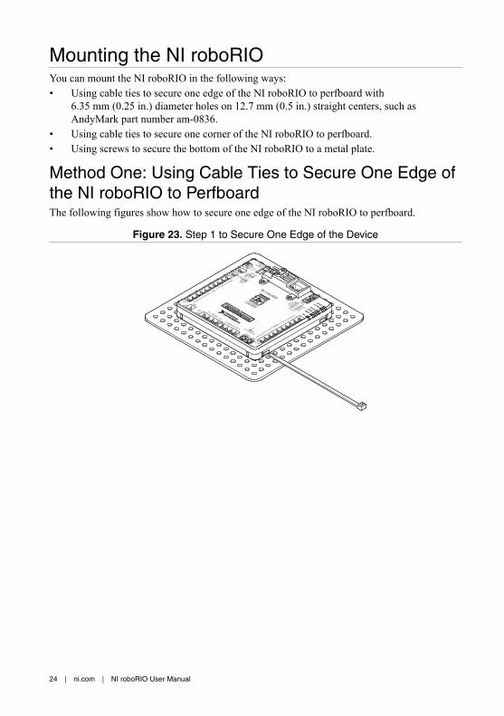
Mounting the NI roboRIOYou can mount the NI roboRIO in the following ways:• Using cable ties to secure one edge of the NI roboRIO to perfboard with
6.35 mm (0.25 in.) diameter holes on 12.7 mm (0.5 in.) straight centers, such asAndyMark part number am-0836.
• Using cable ties to secure one corner of the NI roboRIO to perfboard.• Using screws to secure the bottom of the NI roboRIO to a metal plate.
Method One: Using Cable Ties to Secure One Edge ofthe NI roboRIO to PerfboardThe following figures show how to secure one edge of the NI roboRIO to perfboard.
Figure 23. Step 1 to Secure One Edge of the Device
24 | ni.com | NI roboRIO User Manual

Figure 24. Step 2 to Secure One Edge of the Device
Figure 25. Step 3 to Secure One Edge of the Device
NI roboRIO User Manual | © National Instruments | 25

Figure 26. Step 4 to Secure One Edge of the Device
Method Two: Using Cable Ties to Secure One Cornerof the NI roboRIO to PerfboardThe following figures show how to secure one corner of the NI roboRIO to perfboard.
Figure 27. Step 1 to Secure One Corner of the Device
26 | ni.com | NI roboRIO User Manual
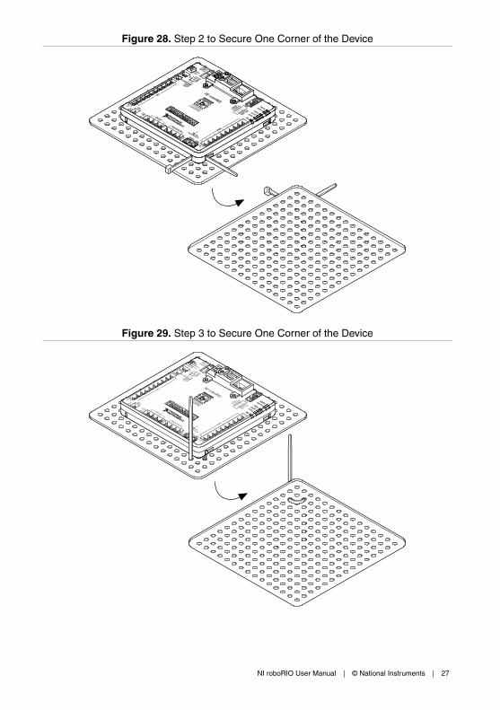
Figure 28. Step 2 to Secure One Corner of the Device
Figure 29. Step 3 to Secure One Corner of the Device
NI roboRIO User Manual | © National Instruments | 27

Figure 30. Step 4 to Secure One Corner of the Device
Figure 31. Step 5 to Secure One Corner of the Device
28 | ni.com | NI roboRIO User Manual
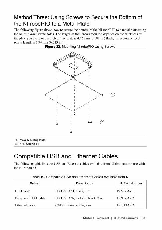
Method Three: Using Screws to Secure the Bottom ofthe NI roboRIO to a Metal PlateThe following figure shows how to secure the bottom of the NI roboRIO to a metal plate usingthe built-in 4-40 screw holes. The length of the screws required depends on the thickness ofthe plate you use. For example, if the plate is 4.76 mm (0.188 in.) thick, the recommendedscrew length is 7.94 mm (0.313 in.).
Figure 32. Mounting NI roboRIO Using Screws
2
1
1. Metal Mounting Plate2. 4-40 Screws x 4
Compatible USB and Ethernet CablesThe following table lists the USB and Ethernet cables available from NI that you can use withthe NI roboRIO.
Table 19. Compatible USB and Ethernet Cables Available from NI
Cable Description NI Part Number
USB cable USB 2.0 A/B, black, 1 m 192256A-01
Peripheral USB cable USB 2.0 A/A, locking, black, 2 m 152166A-02
Ethernet cable CAT-5E, thin profile, 2 m 151733A-02
NI roboRIO User Manual | © National Instruments | 29

Caution To ensure the specified EMC performance, the maximum length for DIO,RS-232, I2C, CAN, SPI, PWM, AI, Relay, and RSL signal wires is 2.0 m (6.56 ft).The maximum length for USB cables is 5.0 m (16.40 ft). The maximum length forEthernet cables is 30.0 m (98.43 ft).
WarrantyFor customers other than private individual users in the EU: The NI roboRIO is warrantedagainst defects in materials and workmanship for a period of three years from the date ofshipment, as evidenced by receipts or other documentation. NI will, at its option, repair orreplace equipment that proves to be defective during the warranty period. This warrantyincludes parts and labor.
For private individual users in the EU: Based on your statutory rights, NI will—through itsdistributor—cure defects in materials and workmanship within two years from delivery.
Worldwide Support and ServicesThe National Instruments website is your complete resource for technical support. At ni.com/support, you have access to everything from troubleshooting and application developmentself-help resources to email and phone assistance from NI Application Engineers.
Visit ni.com/services for NI Factory Installation Services, repairs, extended warranty, andother services.
Visit ni.com/register to register your National Instruments product. Product registrationfacilitates technical support and ensures that you receive important information updates fromNI.
A Declaration of Conformity (DoC) is our claim of compliance with the Council of theEuropean Communities using the manufacturer’s declaration of conformity. This systemaffords the user protection for electromagnetic compatibility (EMC) and product safety. Youcan obtain the DoC for your product by visiting ni.com/certification. If your product supportscalibration, you can obtain the calibration certificate for your product at ni.com/calibration.
National Instruments corporate headquarters is located at 11500 North Mopac Expressway,Austin, Texas, 78759-3504. National Instruments also has offices located around the world.For telephone support in the United States, create your service request at ni.com/support ordial 1 866 ASK MYNI (275 6964). For telephone support outside the United States, visit theWorldwide Offices section of ni.com/niglobal to access the branch office websites, whichprovide up-to-date contact information, support phone numbers, email addresses, and currentevents.
30 | ni.com | NI roboRIO User Manual

Refer to the NI Trademarks and Logo Guidelines at ni.com/trademarks for information on National Instruments trademarks.Other product and company names mentioned herein are trademarks or trade names of their respective companies. For patentscovering National Instruments products/technology, refer to the appropriate location: Help»Patents in your software, thepatents.txt file on your media, or the National Instruments Patent Notice at ni.com/patents. You can find information aboutend-user license agreements (EULAs) and third-party legal notices in the readme file for your NI product. Refer to the ExportCompliance Information at ni.com/legal/export-compliance for the National Instruments global trade compliance policy andhow to obtain relevant HTS codes, ECCNs, and other import/export data. NI MAKES NO EXPRESS OR IMPLIED WARRANTIESAS TO THE ACCURACY OF THE INFORMATION CONTAINED HEREIN AND SHALL NOT BE LIABLE FOR ANY ERRORS.U.S. Government Customers: The data contained in this manual was developed at private expense and is subject to theapplicable limited rights and restricted data rights as set forth in FAR 52.227-14, DFAR 252.227-7014, and DFAR 252.227-7015.
© 2015 National Instruments. All rights reserved.
375274A-01 Jul15