NI PXIe-4353 and TB-4353 Terminal Block Installation … · TERMINAL BLOCK INSTALLATION GUIDE AND...
20
TERMINAL BLOCK INSTALLATION GUIDE AND SPECIFICATIONS NI PXIe-4353 and TB-4353 NI SC Express is a family of PXI Express modules with integrated data acquisition and signal conditioning. These devices offer increased speed, accuracy, and synchronization features that are well suited for high-density sensor measurement and signal-conditioning systems. Accessories required for signal connections to these modules include a front-mount terminal block with screw-terminal connectivity. This guide describes how to install and configure the NI SC Express PXIe-4353 module and terminal block, connect signals, and verify that the system is working properly. Current versions of NI documents are available at ni.com/manuals. The NI PXIe-4353 is a high-accuracy thermocouple input module that supports up to 32 thermocouple inputs and has 8 cold-junction compensation (CJC) channels for improved CJC accuracy. The TB-4353 terminal block has eight thermistors that provide CJC for thermocouples. The TB-4353 terminal block is designed for use with the following module as specified: NI PXIe-4353......................................................... ±80 mV maximum voltage measurement range Note Refer to the NI PXIe-4353 Specifications document for additional voltage and safety information. The keying of this terminal block prevents it from connecting to other modules that could be damaged by the voltage present on the terminal block. However, you should only use this terminal block with its supported modules. Caution When hazardous voltages (>30 V rms /42.4 V pk /60 VDC) are present on any terminal, safety low-voltage (30 V rms /42.4 V pk /60 VDC) cannot be connected to any other terminal. Caution Do not supply hazardous voltages (>30 V rms /42.4 V pk /60 VDC) to the terminal block without the terminal block being connected to the NI PXIe-4353. Caution Refer to the Read Me First: Safety and Electromagnetic Compatibility document for important safety and electromagnetic compatibility information. To obtain a copy of this document online, visit ni.com/manuals, and search for the document title. Contents What You Need to Get Started ............................................................................................................ 2 Installation ........................................................................................................................................... 3 Step 1. Install the Software .......................................................................................................... 3 Step 2. Unpack and Install the Module ........................................................................................ 3 Step 3. Connect the Signals ......................................................................................................... 5 Step 4. Install the Terminal Block ............................................................................................... 7 Step 5. Confirm NI SC Express Module Recognition ................................................................. 8 ni.com/manuals Deutsch Français
-
Upload
nguyenthuan -
Category
Documents
-
view
247 -
download
0
Transcript of NI PXIe-4353 and TB-4353 Terminal Block Installation … · TERMINAL BLOCK INSTALLATION GUIDE AND...

TERMINAL BLOCK INSTALLATION GUIDE AND SPECIFICATIONS
NI PXIe-4353 and TB-4353
NI SC Express is a family of PXI Express modules with integrated data acquisition and signal conditioning. These devices offer increased speed, accuracy, and synchronization features that are well suited for high-density sensor measurement and signal-conditioning systems. Accessories required for signal connections to these modules include a front-mount terminal block with screw-terminal connectivity.
This guide describes how to install and configure the NI SC Express PXIe-4353 module and terminal block, connect signals, and verify that the system is working properly. Current versions of NI documents are available at ni.com/manuals.
The NI PXIe-4353 is a high-accuracy thermocouple input module that supports up to 32 thermocouple inputs and has 8 cold-junction compensation (CJC) channels for improved CJC accuracy. The TB-4353 terminal block has eight thermistors that provide CJC for thermocouples.
The TB-4353 terminal block is designed for use with the following module as specified:
NI PXIe-4353.........................................................±80 mV maximum voltage measurement range
Note Refer to the NI PXIe-4353 Specifications document for additional voltage and safety information.
The keying of this terminal block prevents it from connecting to other modules that could be damaged by the voltage present on the terminal block. However, you should only use this terminal block with its supported modules.
Caution When hazardous voltages (>30 Vrms/42.4 Vpk/60 VDC) are present on any terminal, safety low-voltage (30 Vrms/42.4 Vpk /60 VDC) cannot be connected to any other terminal.
Caution Do not supply hazardous voltages (>30 Vrms/42.4 Vpk/60 VDC) to the terminal block without the terminal block being connected to the NI PXIe-4353.
Caution Refer to the Read Me First: Safety and Electromagnetic Compatibility document for important safety and electromagnetic compatibility information. To obtain a copy of this document online, visit ni.com/manuals, and search for the document title.
ContentsWhat You Need to Get Started ............................................................................................................ 2Installation ........................................................................................................................................... 3
Step 1. Install the Software .......................................................................................................... 3Step 2. Unpack and Install the Module........................................................................................ 3Step 3. Connect the Signals ......................................................................................................... 5Step 4. Install the Terminal Block ............................................................................................... 7Step 5. Confirm NI SC Express Module Recognition ................................................................. 8
ni.com/manuals
DeutschFrançais

NI PXIe-4353 and TB-4353 Terminal Block Installation Guide 2 ni.com
Step 6. Run Test Panels ............................................................................................................... 9Step 7. Take an NI-DAQmx Measurement ................................................................................. 9
NI-DAQmx Channels and Tasks ......................................................................................... 9Configure a Task Using the DAQ Assistant from MAX..................................................... 10
Step 8. Use Your NI SC Express 4353 in an Application ........................................................... 10Programming Examples....................................................................................................... 10
Removal ............................................................................................................................................... 11Step 1. Remove the Terminal Block............................................................................................ 11Step 2. Remove the Module......................................................................................................... 12
Create a Simulated Device................................................................................................................... 13Cold-Junction Compensation............................................................................................................... 13
Minimizing Thermal Gradients ................................................................................................... 15Calibrate the Module and Terminal Block .......................................................................................... 15More Information................................................................................................................................. 15
Troubleshooting ........................................................................................................................... 15Where to Go for Support ..................................................................................................................... 16Specifications....................................................................................................................................... 17
Electrical ...................................................................................................................................... 17Calibration ................................................................................................................................... 17Mechanical................................................................................................................................... 17Physical ........................................................................................................................................ 18Environmental Specifications ...................................................................................................... 18
Operating Environment........................................................................................................ 18Storage Environment ................................................................................................................... 18Shock and Vibration .................................................................................................................... 19Safety Voltages ............................................................................................................................ 19Safety Standards .......................................................................................................................... 19Electromagnetic Compatibility .................................................................................................... 19CE Compliance ............................................................................................................................ 20Online Product Certification........................................................................................................ 20Environmental Management........................................................................................................ 20
What You Need to Get StartedTo set up and use the TB-4353 terminal block with the NI PXIe-4353 module, you need the following items:
• Hardware
– TB-4353 terminal block
– NI PXIe-4353 module
– PXIe chassis
– Shielded cabling and sensors as required for your application
• Tools
– Number 1 and 2 Phillips-head screwdrivers
– 1/8 in. flathead screwdriver
– Long-nose pliers
– Wire cutter
– Wire insulation stripper

© National Instruments Corporation 3 NI PXIe-4353 and TB-4353 Terminal Block Installation Guide
• Documentation
– NI PXIe-4353 and TB-4353 Terminal Block Installation Guide and Specifications
– Read Me First: Safety and Electromagnetic Compatibility
– NI PXIe-4353 User Manual
– PXIe chassis user manual
You can download needed documents from ni.com/manuals.
Installation
Step 1. Install the Software
Note You must be an administrator to install NI software and devices on your computer.
Before installing the NI SC Express hardware, make sure the following are installed in the order indicated:
1. Your application software, such as LabVIEW, LabWindows™/CVI™ or .NET.
2. NI-DAQmx 9.1 or later.
Note When installing NI application software, such as NI LabVIEW, refer to the NI-DAQmx Readme on the software media for supported software versions. Back up any applications before upgrading software or modifying the application.
Tip Using an NI-DAQmx simulated device, you can test NI-DAQmx applications without installing hardware. Refer to the Create a Simulated Device section for instructions for creating NI-DAQmx simulated devices.
Step 2. Unpack and Install the ModuleRemove the packaging and inspect the module. Contact NI if the module is damaged. Do not install a damaged module.
Caution The module is static sensitive. Always properly ground yourself and the equipment when handling or connecting to the module.
Complete the following steps to install the NI SC Express module while referring to Figures 1 and 2:
1. Power off the NI PXI Express chassis. Refer to the chassis manual for chassis installation and configuration instructions.
Caution Refer to the Read Me First: Safety and Electromagnetic Compatibility, included with your module, before connecting or disconnecting signal wires.
2. Identify a supported PXI Express slot in the chassis. NI SC Express devices can be placed only in PXI Express Peripheral slots, PXI Express Hybrid Peripheral slots, and PXI Express System Timing slots. Refer to the chassis documentation for details.

NI PXIe-4353 and TB-4353 Terminal Block Installation Guide 4 ni.com
Figure 1. Symbols for PXI Express/ PXI Express Hybrid/ PXI Slots
3. Remove the filler panel and touch any metal part of the chassis to discharge static electricity.
4. Place the module edges into the module guides at the top and bottom of the slot.
Caution When installing the module, make sure both edges are positioned inside the guides and that the module components do not come into contact with adjacent modules.
5. Slide the module along the guides until it reaches the rear connector, then seat the module by pushing the front panel until it is flush with the front panel of the chassis.
6. Secure the module to the chassis using the front-panel captive screws, shown in Figure 2. Tighten the screws to 0.31 N·m (2.7 lb · in.).
Figure 2. Installing NI SC Express Modules
1 PXI Express System Controller Slot2 PXI Peripheral Slot
3 PXI Express Hybrid Peripheral Slot4 PXI Express System Timing Slot
1 Captive Screws
NI PXIe-1062Q
1 2 3 4
NI PXIe-1062Q
COOLING CLEARANCE AND FAN FILTER MAINTENANCE REQUIRED. SEE MANUAL.
COOLING CLEARANCE AND FAN FILTER MAINTENANCE REQUIRED. SEE MANUAL.
1

© National Instruments Corporation 5 NI PXIe-4353 and TB-4353 Terminal Block Installation Guide
Step 3. Connect the Signals
Caution To ensure the specified EMC performance, operate this product only with shielded cables and accessories.
Note Refer to the Read Me First: Safety and Electromagnetic Compatibility document before removing equipment covers or connecting or disconnecting any signal wires.
To connect signals to the terminal block, refer to Figures 3 and 4 while completing the following steps:
Note You can find the pinout names and locations in MAX at any time by right-clicking the device name under Devices and Interfaces and selecting Device Pinouts.
1. Loosen the captive top cover screws and remove the top cover.
2. Loosen the strain-relief screws and remove the strain-relief bar.
3. Prepare the signal wire by stripping the insulation no more than 7 mm (0.28 in.).
4. Run the signal wires through the strain-relief opening.
Figure 3. TB-4353 Parts Locator Diagram
1 Strain-Relief Screws2 Strain-Relief Bar3 Tie Wrap Holes
4 Ground Lugs5 Terminal Block to Module Connector6 Captive Top Cover Screws
7 Top Cover8 Tie Wraps9 Signal Wires
5
9
8
7
6
6
4
3
4
1
2
1

NI PXIe-4353 and TB-4353 Terminal Block Installation Guide 6 ni.com
5. Insert the stripped end of the signal wires fully into the appropriate terminal. Refer to the label next to each screw terminal to determine the function of the terminal. The NI PXIe-4353 User Manual provides more detailed wiring information. Make sure no exposed wire extends past the screw terminal. Exposed wire increases the risk of a short circuit that can cause circuit failure.
Figure 4. TB-4353 Circuit Board Parts Locator Diagram
6. Tighten the terminal screws to a torque of 0.3 N·m (2.7 lb · in.).
Note In most applications, connection to the COM terminal is not necessary. However, its proper connection will improve common-mode rejection performance when two or more channels are connected to different common-mode voltages. In this case, connect COM to earth ground or a fixed reference voltage, depending on your isolation requirements. All thermocouple channels with respect to COM on the NI PXIe-4353 must remain within ±10 V. Refer to the NI PXIe-4353 User Manual for more information about proper connection of the COM terminal.
Caution Any wires connected to the ground must be sufficiently insulated from high voltage.
7. Attach cable shields to the ground lugs to connect them to chassis ground.
Note Refer to the NI PXIe-4353 User Manual for details about shielding the signals.
8. Reinstall the strain-relief bar and tighten the strain-relief screws.
9. Use tie wraps to connect the signal wires to the tie-wrap holes for additional strain relief when necessary.
10. Reinstall the top cover and tighten the captive top cover screws.
1 Thermistors 2 Screw Terminals
CO
M
TC
0T
C1
TC
2T
C3
TC
4T
C5
TC
6T
C7
TC
8T
C9
TC10
TC11
TC12
TC13
TC14
TC15
TC18
TC17
TC16
TC19
TC20
TC21
TC22
TC23
TC26
TC25
TC24
TC27
TC28
TC29
TC30
TC31
+ –
+ –
+ –
+ –
+ –
+ –
+ –
+ –
+ –
+ –
+ –
+ –
+ –
+ –
+ –
+ –
+ –
+ –
+ –
+ –
+ –
+ –
+ –
+ –
+ –
+ –
+ –
+ –
+ –
+ –
+ –
+ –
1
1
1 1
11112 2 2 2 2
© National Instruments Corporation 7 NI PXIe-4353 and TB-4353 Terminal Block Installation Guide
For information about CJC and accuracy considerations refer to the Cold-Junction Compensation section.
Note For information about sensors, go to ni.com/sensors.
Step 4. Install the Terminal Block
Caution Do not supply hazardous voltages (>30 Vrms/42.4 Vpk/60 VDC) to the terminal block without the terminal block being connected to the NI PXIe-4353.
Note The chassis can be powered on or off when installing the terminal block.
Refer to Figure 5 to install the terminal block on the module while completing the following steps:
1. Move the TB-4353 into position in front of the NI PXIe-4353 and engage the alignment feature with the guide on the associated module.
Figure 5. Installing the TB-4353 on the NI PXIe-4353 Module
2. Attach the TB-4353 to the NI PXIe-4353 module by pushing the terminal block straight into the module. A spring mechanism will lock in the bottom of the terminal block.
3. Tighten the mounting screw at the top of the TB-4353 to a maximum torque of 0.55 N·m (4.9 lb · in.) to attach it to the NI PXIe-4353 module.
1 PXIe Controller2 PXIe Chassis
3 Mounting Screw4 TB-4353 Terminal Block
5 NI PXIe-4353 Module6 Alignment Feature
COOLING CLEARANCE AND FAN FILTER MAINTENANCE REQUIRED. SEE MANUAL.
COOLING CLEARANCE AND FAN FILTER MAINTENANCE REQUIRED. SEE MANUAL.
2
4
5
6
3
1
NI PXIe-1062Q

NI PXIe-4353 and TB-4353 Terminal Block Installation Guide 8 ni.com
Note For safety purposes and to prevent damage to equipment when high voltages are present, all NI SC Express modules and terminal blocks are keyed to prevent connection between incompatible terminal blocks, modules, and/or cables.
4. Power on the chassis if it is powered off.
Figure 6 shows an example NI SC Express system setup.
Figure 6. Sample NI SC Express System
Step 5. Confirm NI SC Express Module RecognitionTo confirm module recognition, complete the following steps:
Note Make sure you are using the most recent version of NI-DAQmx. If you are using an older version of the driver software, the NI SC Express terminal block may work only in basic functionality mode. Unsupported terminal blocks appear in Measurement & Automation Explorer (MAX) with an X next to them.
1. Launch MAX.
2. Expand Devices and Interfaces»NI-DAQmx Devices to confirm that MAX detects the module and terminal block. The terminal block should appear beneath its associated module. If your module or terminal block is not listed, press <F5> to refresh MAX. If the module is still not recognized, go to ni.com/support/daqmx.
1 Terminal Block 2 Signal Input
NI PXIe-1062Q
COOLING CLEARANCE AND FAN FILTER MAINTENANCE REQUIRED. SEE MANUAL.
COOLING CLEARANCE AND FAN FILTER MAINTENANCE REQUIRED. SEE MANUAL.
2
1

© National Instruments Corporation 9 NI PXIe-4353 and TB-4353 Terminal Block Installation Guide
Tip Using an NI-DAQmx simulated device, you can test NI-DAQmx applications without installing hardware. Refer to the Create a Simulated Device section for instructions for creating NI-DAQmx simulated devices.
3. Right-click the module name and select Self-Test. When the self-test completes, a verification message appears. If an error occurs, refer to ni.com/support/daqmx.
For information about sensors, go to ni.com/sensors.
Step 6. Run Test Panels1. In MAX, expand Devices and Interfaces»NI-DAQmx Devices.
2. Right-click the device, and select Test Panels.
3. Click Start to test device functions, or Help for operating instructions.
To troubleshoot errors, refer to the NI-DAQmx Help, or go to ni.com/support.
Step 7. Take an NI-DAQmx Measurement
NI-DAQmx Channels and TasksRefer to the NI-DAQmx Help for complete information about channels and tasks.
Use the DAQ Assistant to configure virtual channels and tasks in MAX or in your application.
NI PXIe-4353 and TB-4353 Terminal Block Installation Guide 10 ni.com
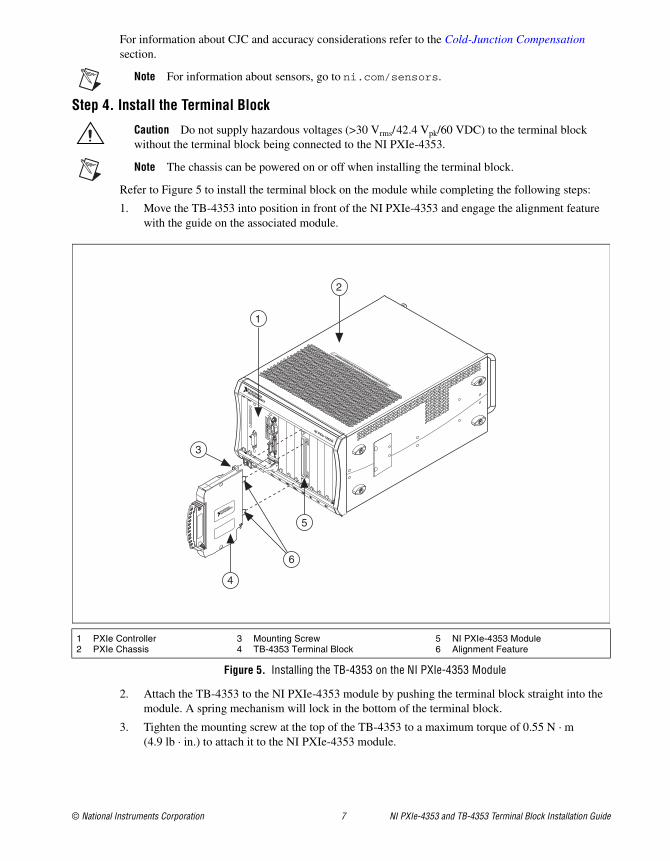
Configure a Task Using the DAQ Assistant from MAXComplete the following steps to create a task using the DAQ Assistant in MAX:
1. In MAX, right-click Data Neighborhood and select Create New to open the DAQ Assistant.
2. Select NI-DAQmx Task and click Next.
3. Select Acquire Signals.
Note The NI PXIe-4353 cannot generate signals.
4. Select Analog Input and the measurement type, such as Temperature»Thermocouple or Voltage.
5. Select the physical channel(s) to use and click Next.
6. Name the task and click Finish.
7. Configure the individual channel settings. Each physical channel you assign to a task receives a virtual channel name. To modify the input range or other settings, select the channel. Click Details for physical channel information. Configure the timing and triggering for your task. Click Run.
Step 8. Use Your NI SC Express 4353 in an ApplicationFor NI software version compatibility, refer to the NI-DAQmx Readme, available from Start»All Programs»National Instruments»NI-DAQmx.
To get started with data acquisition in your application software, refer to the tutorials listed in Table 1.
Programming ExamplesNI-DAQmx includes example programs to help you get started developing an application. LabVIEW and CVI examples are located at Help»Find Examples in your application software. Text-based code examples are located at All Programs»National Instruments»NI-DAQ»Text-Based Code Support»ANSI C Examples. Modify example code and save it in an application, or use examples to develop a new application or add example code to an existing application.
For other examples, go to ni.com/info and enter the Info Code daqmxexp. For additional examples, refer to zone.ni.com .
Table 1. DAQ Assistant Tutorial Locations
Application Tutorial Location
LabVIEW Go to Help»Search the LabVIEW Help. Next, go to Getting Started with LabVIEW»Getting Started with DAQ»Taking an NI-DAQmx Measurement in LabVIEW.
LabWindows/CVI Go to Help»Contents. Next, go to Using LabWindows/CVI»Data Acquisition»Taking an NI-DAQmx Measurement in LabWindows/CVI.
Measurement Studio
Go to NI Measurement Studio Help»Getting Started with the Measurement Studio Class Libraries»Measurement Studio Walkthroughs»Walkthrough: Creating a Measurement Studio NI-DAQmx Application.
LabVIEW SignalExpress*
Go to Help»Taking an NI-DAQmx Measurement in SignalExpress.
* LabVIEW SignalExpress, an easy-to-use configuration-based tool for data logging applications, is at Start»All Programs»National Instruments»LabVIEW SignalExpress.
© National Instruments Corporation 11 NI PXIe-4353 and TB-4353 Terminal Block Installation Guide
Removal
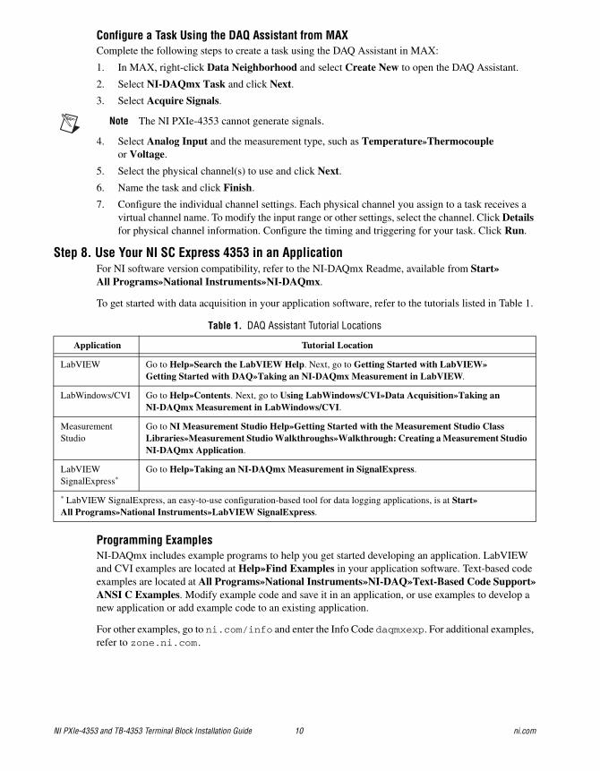
Step 1. Remove the Terminal BlockLater TB-4353 revisions include a latch release that you can use to remove the terminal block from the module. You can remove any TB-4353 revision by tilting the terminal block down and away from the module.
Caution Do not supply hazardous voltages (>30 Vrms/42.4 Vpk/60 VDC) to the terminal block without the terminal block being connected to the NI PXIe-4353.
Refer to Figure 7 to remove the terminal block from the module while completing the following steps:
Note The chassis can be powered on or off when removing the terminal block.
1. Loosen the mounting screw located at the top of the terminal block.
2. To remove the terminal block using a latch release:
a. Raise the latch release using a flathead screwdriver to disengage the latch.
b. With the latch release raised, grasp the terminal block and pull it away from the module.
Figure 7. Removing the TB-4353 from the NI PXIe-4353 Module (Latch Release Method)
Refer to Figure 8 to remove the terminal block from the module while completing the following steps:
To remove the terminal block without using a latch release:
a. Tilt the terminal block down and away from the module to disengage the latch.
b. Grasp the terminal block and pull it away from the module.
1 Mounting Screw2 Latch Release
3 PXIe Controller4 PXIe Chassis
5 TB-4353 Terminal Block
COOLING CLEARANCE AND FAN FILTER MAINTENANCE REQUIRED. SEE MANUAL.
COOLING CLEARANCE AND FAN FILTER MAINTENANCE REQUIRED. SEE MANUAL.
4
3
5
1
2
NI PXIe-4353 and TB-4353 Terminal Block Installation Guide 12 ni.com
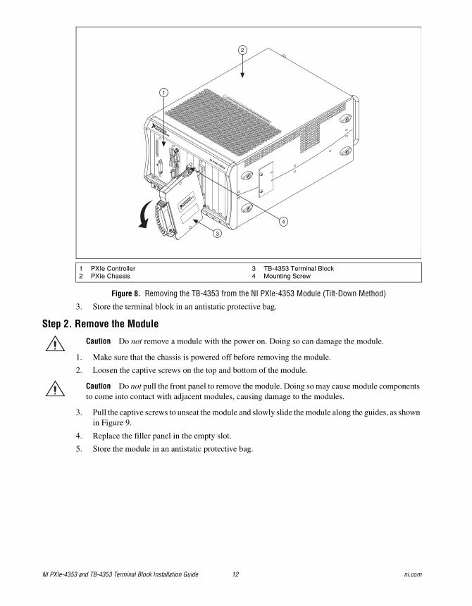
Figure 8. Removing the TB-4353 from the NI PXIe-4353 Module (Tilt-Down Method)
3. Store the terminal block in an antistatic protective bag.
Step 2. Remove the Module
Caution Do not remove a module with the power on. Doing so can damage the module.
1. Make sure that the chassis is powered off before removing the module.
2. Loosen the captive screws on the top and bottom of the module.
Caution Do not pull the front panel to remove the module. Doing so may cause module components to come into contact with adjacent modules, causing damage to the modules.
3. Pull the captive screws to unseat the module and slowly slide the module along the guides, as shown in Figure 9.
4. Replace the filler panel in the empty slot.
5. Store the module in an antistatic protective bag.
1 PXIe Controller2 PXIe Chassis
3 TB-4353 Terminal Block4 Mounting Screw
NI PXIe-1062Q
COOLING CLEARANCE AND FAN FILTER MAINTENANCE REQUIRED. SEE MANUAL.
COOLING CLEARANCE AND FAN FILTER MAINTENANCE REQUIRED. SEE MANUAL.
4
3
2
1

© National Instruments Corporation 13 NI PXIe-4353 and TB-4353 Terminal Block Installation Guide
Figure 9. Removing NI SC Express Modules
Create a Simulated DeviceTo run examples without the hardware installed, use an NI-DAQmx simulated device. To create a simulated device in MAX:
1. Launch MAX.
2. Right-click Devices and Interfaces»Create New.
3. From the dialog, select Simulated NI-DAQmx Device or Modular Instrument.
4. Type 4353 in the text box at the top of the window.
5. Select the device from the list provided.
6. Click OK.
Cold-Junction CompensationCold-junction compensation is the process of measuring the temperature of the screw terminal junction for the thermocouple and applying a representative compensating voltage to the voltage measured by the thermocouple channel. The accuracy of the cold-junction temperature measurement is a key part of the accuracy of the overall thermocouple temperature measurement. The TB-4353 is carefully designed to ensure high-accuracy cold-junction temperature measurements, under a variety of conditions; however, care must be taken to ensure the best possible accuracy. Refer to the Minimizing Thermal Gradients section for guidelines to minimize thermal gradients that could impact the CJC accuracy. Refer to the Specifications section for the CJC accuracy specifications.
1 Captive Screws (Use to remove modules.) 2 Front Panel (Do not use to remove modules.)
NI PXIe-1062Q
COOLING CLEARANCE AND FAN FILTER MAINTENANCE REQUIRED. SEE MANUAL.
COOLING CLEARANCE AND FAN FILTER MAINTENANCE REQUIRED. SEE MANUAL.
1 2
NI PXIe-4353 and TB-4353 Terminal Block Installation Guide 14 ni.com
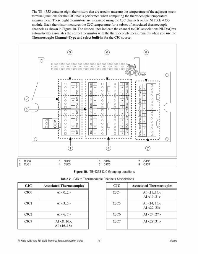
The TB-4353 contains eight thermistors that are used to measure the temperature of the adjacent screw terminal junctions for the CJC that is performed when computing the thermocouple temperature measurement. These eight thermistors are measured using the CJC channels on the NI PXIe-4353 module. Each thermistor measures the CJC temperature for a subset of associated thermocouple channels as shown in Figure 10. The dashed lines indicate the channel to CJC associations.NI-DAQmx automatically associates the correct thermistor with the thermocouple measurements when you use the Thermocouple Channel-Type and select built-in for the CJC source.
Figure 10. TB-4353 CJC Grouping Locations
1 CJC02 CJC1
3 CJC24 CJC3
5 CJC46 CJC5
7 CJC68 CJC7
Table 2. CJC to Thermocouple Channels Associations
CJC Associated Thermocouples CJC Associated Thermocouples
CJC0 AI <0..2> CJC4 AI <11..13>,AI <19..21>
CJC1 AI <3..5> CJC5 AI <14, 15>,AI <22, 23>
CJC2 AI <6, 7> CJC6 AI <24..27>
CJC3 AI <8..10>,AI <16..18>
CJC7 AI <28..31>
CO
M
TC
0T
C1
TC
2T
C3
TC
4T
C5
TC
6T
C7
TC
8T
C9
TC10
TC11
TC12
TC13
TC14
TC15
TC18
TC17
TC16
TC19
TC20
TC21
TC22
TC23
TC26
TC25
TC24
TC27
TC28
TC29
TC30
TC31
+ –
+ –
+ –
+ –
+ –
+ –
+ –
+ –
+ –
+ –
+ –
+ –
+ –
+ –
+ –
+ –
+ –
+ –
+ –
+ –
+ –
+ –
+ –
+ –
+ –
+ –
+ –
+ –
+ –
+ –
+ –
+ –
1
2
5
3 6 8
4 7
© National Instruments Corporation 15 NI PXIe-4353 and TB-4353 Terminal Block Installation Guide
Minimizing Thermal GradientsThermal gradients can be caused by changes in the ambient air temperature near the terminal block, heat sources from other devices near the terminal block, or by the thermocouple wire if it conducts heat to or away from the terminal junctions. For optimal CJC accuracy performance, ensure that changes in ambient temperature and temperature gradients near the terminal block are kept to a minimum. Follow these guidelines to minimize thermal gradients that could impact the CJC accuracy:
• Use the smallest gauge thermocouple wire suitable for the application. Smaller wire transfers less heat to or from the terminal junction.
• Run thermocouple wiring together near the terminal block to keep the wires at the same temperature.
• Avoid running thermocouple wires near hot or cold objects.
• If you connect any extension wires to thermocouple wires, use wires made of the same conductive material as the thermocouple wires.
• Minimize adjacent heat sources and air flow across the terminal block.
• Keep the ambient temperature as stable as possible.
• Keep the terminal block, module, and chassis in a stable and consistent orientation.
• Install the PXIe filler panels in any unused slots.
• When stacking the system, avoid stacking above a heat source as heat rises and can introduce error.
• Allow the thermal gradients to settle after a change in system power or in ambient temperature. A change in system power can happen when the system powers on. Refer to the warm-up time in the NI PXIe-4353 Specifications for more information.
• Replace the fan filters in the PXIe chassis regularly to ensure proper system cooling.
Calibrate the Module and Terminal BlockTo download available external calibration documents, visit the National Instruments Web site at ni.com/info and enter the Info Code manualcal. For external calibration of products not listed there, Basic Calibration Service or Detailed Calibration Service is recommended. You can get information about both of these calibration services at ni.com/calibration. NI recommends performing an external calibration once a year.
More InformationAfter you install NI-DAQmx, the NI-DAQmx documentation is available from Start»All Programs»National Instruments»NI-DAQ. Additional resources are online at ni.com/gettingstarted.
You can access online device documentation by right-clicking your module in MAX and selecting Help»Online Device Documentation. A browser window opens to ni.com/manuals with the results of a search for relevant documents. If you do not have Web access, documents for supported modules are included on the NI-DAQmx media.
Troubleshooting• Go to ni.com/support/install or ni.com/kb.
• If you need to return your National Instruments hardware for repair or device calibration, go to ni.com/info and enter rdsenn to start the Return Merchandise Authorization (RMA) process.
NI PXIe-4353 and TB-4353 Terminal Block Installation Guide 16 ni.com
Where to Go for SupportThe National Instruments Web site is your complete resource for technical support. At ni.com/support you have access to everything from troubleshooting and application development self-help resources to email and phone assistance from NI Application Engineers.
A Declaration of Conformity (DoC) is our claim of compliance with the Council of the European Communities using the manufacturer’s declaration of conformity. This system affords the user protection for electromagnetic compatibility (EMC) and product safety. You can obtain the DoC for your product by visiting ni.com/certification. If your product supports calibration, you can obtain the calibration certificate for your product at ni.com/calibration.
National Instruments corporate headquarters is located at 11500 North Mopac Expressway, Austin, Texas, 78759-3504. National Instruments also has offices located around the world to help address your support needs. For telephone support in the United States, create your service request at ni.com/support and follow the calling instructions or dial 512 795 8248. For telephone support outside the United States, visit the Worldwide Offices section of ni.com/niglobal to access the branch office Web sites, which provide up-to-date contact information, support phone numbers, email addresses, and current events.

© National Instruments Corporation 17 NI PXIe-4353 and TB-4353 Terminal Block Installation Guide
Specifications
Note NI PXIe-4353 module specifications are located in the NI PXIe-4353 Specifications document.
All specifications are typical for the range of 0 °C to 55 °C unless otherwise specified.
ElectricalCold-junction sensors
Sensor type.....................................................NTC thermistor, 10 k nominal
Steinhart-Hart scaling coefficients1
A.............................................................1.1288643 10–3
B.............................................................2.3414908 10–4
C.............................................................8.7706554 10–8
CJC accuracy2
Input voltage range ................................................Refer to the NI PXIe-4353 Specifications document.
CalibrationCalibration interval ................................................1 year
MechanicalScrew terminal wire gauge.....................................14 AWG max
1 Refer to the software documentation for details about scaling the thermistor readings.2 This includes the combined effects of the thermistor accuracy and the temperature difference between the screw terminal and
its associated thermistor.This represents performance for wire gauges of 24 AWG and smaller.
Terminal Block
Typical Maximum
23 °C ±5 °C 0 °C to 55 °C 23 °C ±5 °C 0 °C to 55 °C
TB-4353 0.20 °C 0.35 °C 0.30 °C 0.45 °C
NI PXIe-4353 and TB-4353 Terminal Block Installation Guide 18 ni.com
Physical
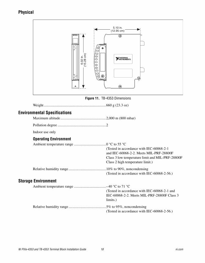
Figure 11. TB-4353 Dimensions
Weight ....................................................................660 g (23.3 oz)
Environmental SpecificationsMaximum altitude..................................................2,000 m (800 mbar)
Pollution degree .....................................................2
Indoor use only
Operating EnvironmentAmbient temperature range ...................................0 °C to 55 °C
(Tested in accordance with IEC-60068-2-1and IEC-60068-2-2. Meets MIL-PRF-28800F Class 3 low temperature limit and MIL-PRF-28800F Class 2 high temperature limit.)
Relative humidity range .........................................10% to 90%, noncondensing(Tested in accordance with IEC-60068-2-56.)
Storage EnvironmentAmbient temperature range ...................................–40 °C to 71 °C
(Tested in accordance with IEC-60068-2-1 and IEC-60068-2-2. Meets MIL-PRF-28800F Class 3 limits.)
Relative humidity range .........................................5% to 95%, noncondensing (Tested in accordance with IEC-60068-2-56.)
5.10 in.(12.95 cm)
6.02
in.
(15.
28 c
m)
© National Instruments Corporation 19 NI PXIe-4353 and TB-4353 Terminal Block Installation Guide
Shock and VibrationOperating shock .....................................................30 g peak, half-sine, 11 ms pulse
(Tested in accordance with IEC-60068-2-27. Meets MIL-PRF-28800F Class 2 limits.)
Random vibration
Operating .......................................................5 Hz to 500 Hz, 0.3 grms
Nonoperating .................................................5 Hz to 500 Hz, 2.4 grms (Tested in accordance with IEC-60068-2-64. Nonoperating test profile exceeds the requirements of MIL-PRF-28800F, Class 3.)
Safety VoltagesRefer to the NI PXIe-4353 Specifications document for maximum voltage limits.
Isolation
Channel-to-channel ........................................None
Channel-to-earth ground ................................300 Vrms, Measurement Category II
Measurement Category II is for measurements performed on circuits directly connected to the electrical distribution system. This category refers to local-level electrical distribution, such as that provided by a standard wall outlet, for example, 115 V for U.S. or 230 V for Europe.
Caution Do not connect the TB-4353 to signals or use for measurements within Measurement Categories III or IV.
Caution The protection provided by the TB-4353 can be impaired if it is used in a manner not described in this document.
Safety StandardsThis product meets the requirements of the following standards of safety for electrical equipment for measurement, control, and laboratory use:
• IEC 61010-1, EN 61010-1
• UL 61010-1, CSA 61010-1
Note For UL and other safety certifications, refer to the product label or the Online Product Certification section.
Electromagnetic CompatibilityThis product meets the requirements of the following EMC standards for electrical equipment for measurement, control, and laboratory use:
• EN 61326-1 (IEC 61326-1): Class A emissions; Basic immunity
• EN 55011 (CISPR 11): Group 1, Class A emissions
• AS/NZS CISPR 11: Group 1, Class A emissions
• FCC 47 CFR Part 15B: Class A emissions
• ICES-001: Class A emissions
Note In the United States (per FCC 47 CFR), Class A equipment is intended for use in commercial, light-industrial, and heavy-industrial locations. In Europe, Canada, Australia and New Zealand (per CISPR 11) Class A equipment is intended for use only in heavy-industrial locations.

CVI, LabVIEW, National Instruments, NI, ni.com, the National Instruments corporate logo, and the Eagle logo are trademarks of National Instruments Corporation. Refer to the Trademark Information at ni.com/trademarks for other National Instruments trademarks. The mark LabWindows is used under a license from Microsoft Corporation. Windows is a registered trademark of Microsoft Corporation in the United States and other countries. Other product and company names mentioned herein are trademarks or trade names of their respective companies. For patents covering National Instruments products/technology, refer to the appropriate location: Help»Patents in your software, the patents.txt file on your media, or the National Instruments Patent Notice at ni.com/patents. Refer to the Export Compliance Information at ni.com/legal/export-compliance for the National Instruments global trade compliance policy and how to obtain relevant HTS codes, ECCNs, and other import/export data.
© 2010–2012 National Instruments Corporation. All rights reserved. 375492B-01 Jan12
Note Group 1 equipment (per CISPR 11) is any industrial, scientific, or medical equipment that does not intentionally generates radio frequency energy for the treatment of material or inspection/analysis purposes.
Note For EMC declarations and certifications, refer to the Online Product Certification section.
Note For EMC compliance, operate this product with shielded cables.
CE ComplianceThis product meets the essential requirements of applicable European Directives as follows:
• 2006/95/EC; Low-Voltage Directive (safety)
• 2004/108/EC; Electromagnetic Compatibility Directive (EMC)
Online Product CertificationRefer to the product Declaration of Conformity (DoC) for additional regulatory compliance information. To obtain product certifications and the DoC for this product, visit ni.com/certification, search by model number or product line, and click the appropriate link in the Certification column.
Environmental ManagementNI is committed to designing and manufacturing products in an environmentally responsible manner. NI recognizes that eliminating certain hazardous substances from our products is beneficial to the environment and to NI customers.
For additional environmental information, refer to the NI and the Environment Web page at ni.com/environment. This page contains the environmental regulations and directives with which NI complies, as well as other environmental information not included in this document.
Waste Electrical and Electronic Equipment (WEEE)EU Customers At the end of the product life cycle, all products must be sent to a WEEE recycling center. For more information about WEEE recycling centers, National Instruments WEEE initiatives, and compliance with WEEE Directive 2002/96/EC on Waste and Electronic Equipment, visit ni.com/environment/weee.
RoHSNational Instruments (RoHS)
National Instruments RoHS ni.com/environment/rohs_china(For information about China RoHS compliance, go to ni.com/environment/rohs_china.)