NI PXIe-1435 User Guide and Specifications - … · 2018-07-12 · NI PXIe-1435 User Guide and...
16
NI PXIe-1435 User Guide and Specifications The NI PXIe-1435 (NI 1435) is a PXI Express (PXIe) image acquisition device that supports Base, Medium, Full, and Extended Full configuration Camera Link cameras and supports Power over Camera Link (PoCL). This document describes how to install and configure the necessary hardware and software components to begin using the NI 1435. Required Components The following items are necessary to set up and use the NI 1435: ❑ NI 1435 image acquisition device ❑ Camera Link camera ❑ Camera Link cables – One SDR Camera Link cable for Base configuration cameras – Two SDR Camera Link cables of the same length for Medium, Full, or Extended Full configuration cameras National Instruments recommends that you use the following cables to connect your camera: – MDR to SDR Camera Link cable (part number 199745A-05) – SDR to SDR Camera Link cable (part number 199746A-05) Note To ensure the high-speed signaling of the Camera Link interface, National Instruments recommends that you purchase a Camera Link cable rather than build a custom cable. ❑ One of the following system considerations: – PXI Express/CompactPCI Express chassis with a PXI Express/CompactPCI Express embedded controller – MXI kit and a PC running Microsoft Windows 7 (32-bit and 64-bit versions)/Vista (32-bit and 64-bit versions)/XP SP2 (32-bit)/Server 2008 R2/Server 2003 R2 (32-bit) ❑ NI-IMAQ 4.6 or later driver software, which is included with NI Vision Acquisition Software ❑ Optional software for developing machine vision applications: – NI Vision Builder for Automated Inspection – NI Vision Development Module, which requires one of the following application development environments: • LabVIEW • LabWindows ™ /CVI ™ • Microsoft Visual Studio
Transcript of NI PXIe-1435 User Guide and Specifications - … · 2018-07-12 · NI PXIe-1435 User Guide and...
NI PXIe-1435 User Guide and SpecificationsThe NI PXIe-1435 (NI 1435) is a PXI Express (PXIe) image acquisition device that supports Base, Medium, Full, and Extended Full configuration Camera Link cameras and supports Power over Camera Link (PoCL). This document describes how to install and configure the necessary hardware and software components to begin using the NI 1435.
Required ComponentsThe following items are necessary to set up and use the NI 1435:
❑ NI 1435 image acquisition device
❑ Camera Link camera
❑ Camera Link cables
– One SDR Camera Link cable for Base configuration cameras
– Two SDR Camera Link cables of the same length for Medium, Full, or Extended Full configuration cameras
National Instruments recommends that you use the following cables to connect your camera:
– MDR to SDR Camera Link cable (part number 199745A-05)
– SDR to SDR Camera Link cable (part number 199746A-05)
Note To ensure the high-speed signaling of the Camera Link interface, National Instruments recommends that you purchase a Camera Link cable rather than build a custom cable.
❑ One of the following system considerations:
– PXI Express/CompactPCI Express chassis with a PXI Express/CompactPCI Express embedded controller
– MXI kit and a PC running Microsoft Windows 7 (32-bit and 64-bit versions)/Vista (32-bit and 64-bit versions)/XP SP2 (32-bit)/Server 2008 R2/Server 2003 R2 (32-bit)
❑ NI-IMAQ 4.6 or later driver software, which is included with NI Vision Acquisition Software
❑ Optional software for developing machine vision applications:
– NI Vision Builder for Automated Inspection
– NI Vision Development Module, which requires one of the following application development environments:
• LabVIEW
• LabWindows™/CVI™
• Microsoft Visual Studio
NI PXIe-1435 User Guide 2 ni.com
Safety Information
Caution The following paragraphs contain important safety information you must follow when installing and operating the device.
Do not operate the device in a manner not specified in the documentation. Misuse of the device may result in a hazard and may compromise the safety protection built into the device. If the device is damaged, turn it off and do not use it until service-trained personnel can check its safety. If necessary, return the device to National Instruments for repair.
Keep away from live circuits. Do not remove equipment covers or shields unless you are trained to do so. If signal wires are connected to the device, hazardous voltages can exist even when the equipment is turned off. To avoid a shock hazard, do not perform procedures involving cover or shield removal unless you are qualified to do so. Disconnect all field power prior to removing covers or shields.
If the device is rated for use with hazardous voltages (>30 Vrms, 42.4 Vpk, or 60 Vdc), it may require a safety earth-ground connection wire. Refer to the device specifications for maximum voltage ratings.
Because of the danger of introducing additional hazards, do not install unauthorized parts or modifythe device. Use the device only with the chassis, modules, accessories, and cables specified in the installation instructions. All covers and filler panels must be installed while operating the device.
Do not operate the device in an explosive atmosphere or where flammable gases or fumes may be present. Operate the device only at or below the pollution degree stated in the specifications. Pollution consists of any foreign matter—solid, liquid, or gas—that may reduce dielectric strength or surface resistivity. The following is a description of pollution degrees.
• Pollution Degree 1—No pollution or only dry, nonconductive pollution occurs. The pollution has no effect.
• Pollution Degree 2—Normally only nonconductive pollution occurs. Occasionally, nonconductive pollution becomes conductive because of condensation.
• Pollution Degree 3—Conductive pollution or dry, nonconductive pollution occurs. Nonconductive pollution becomes conductive because of condensation.
Clean the device and accessories by brushing off light dust with a soft, nonmetallic brush. Removeother contaminants with a stiff, nonmetallic brush. The unit must be completely dry and free from contaminants before returning it to service.
You must insulate signal connections for the maximum voltage for which the device is rated. Do not exceed the maximum ratings for the device. Remove power from signal lines before connection to or disconnection from the device.
Caution National Instruments measurement products may be classified as either Measurement Category I or II. Operate products at or below the Measurement Category level specified in the hardware specifications.
Measurement Category1: Measurement circuits are subjected to working voltages2 and transient stresses (overvoltage) from the circuit to which they are connected during measurement or test. Measurement Category establishes standardized impulse withstand voltage levels that commonly
1 Measurement Categories as defined in electrical safety standard IEC 61010-1.2 Working voltage is the highest rms value of an AC or DC voltage that can occur across any particular insulation.
© National Instruments Corporation 3 NI PXIe-1435 User Guide
occur in electrical distribution systems. The following is a description of Measurement (Installation1) Categories:
• Measurement Category I is for measurements performed on circuits not directly connected to the electrical distribution system referred to as MAINS2 voltage. This category is for measurements of voltages from specially protected secondary circuits. Such voltage measurements include signal levels, special equipment, limited-energy parts of equipment, circuits powered by regulated low-voltage sources, and electronics.
• Measurement Category II is for measurements performed on circuits directly connected to the electrical distribution system. This category refers to local-level electrical distribution, such asthat provided by a standard wall outlet (e.g., 115 V for U.S. or 230 V for Europe). Examples of Measurement Category II are measurements performed on household appliances, portable tools, and similar products.
• Measurement Category III is for measurements performed in the building installation at the distribution level. This category refers to measurements on hard-wired equipment such as equipment in fixed installations, distribution boards, and circuit breakers. Other examples are wiring, including cables, bus-bars, junction boxes, switches, socket-outlets in the fixed installation, and stationary motors with permanent connections to fixed installations.
Install Application Software and DriverBefore installing the NI 1435, you must install the application software and device driver. National Instruments provides two options for developing machine vision applications.
• NI Vision Builder for Automated Inspection (Vision Builder AI)—Interactive, menu-driven configuration software for developing, benchmarking, and deploying machine vision applications. You must also install NI-IMAQ.
• NI Vision Development Module—Programming library for developing machine vision and scientific imaging applications. The NI Vision Development Module requires an application development environment—LabVIEW, LabWindows/CVI, or Visual Studio—and NI-IMAQ.
Installing Vision Builder AIInstall the following software to use Vision Builder AI to develop applications.
1. NI-IMAQ—Refer to the NI Vision Acquisition Software Release Notes on the NI Vision Acquisition Software installation media for system requirements and installation instructions for the NI-IMAQ driver.
Documentation for the NI-IMAQ driver software is available by selecting Start»All Programs»National Instruments»Vision»Documentation»NI-IMAQ.
2. Vision Builder AI—Refer to the NI Vision Builder for Automated Inspection Readme for installation instructions.
Documentation for Vision Builder AI is available by selecting Start»All Programs»National Instruments»Vision Builder AI»Documentation.
1 Measurement Category is also referred to as Installation Category.2 MAINS is defined as the (hazardous live) electrical supply system to which equipment is designed to be connected for the
purpose of powering the equipment. Suitably rated measuring circuits may be connected to the MAINS for measuring purposes.
NI PXIe-1435 User Guide 4 ni.com
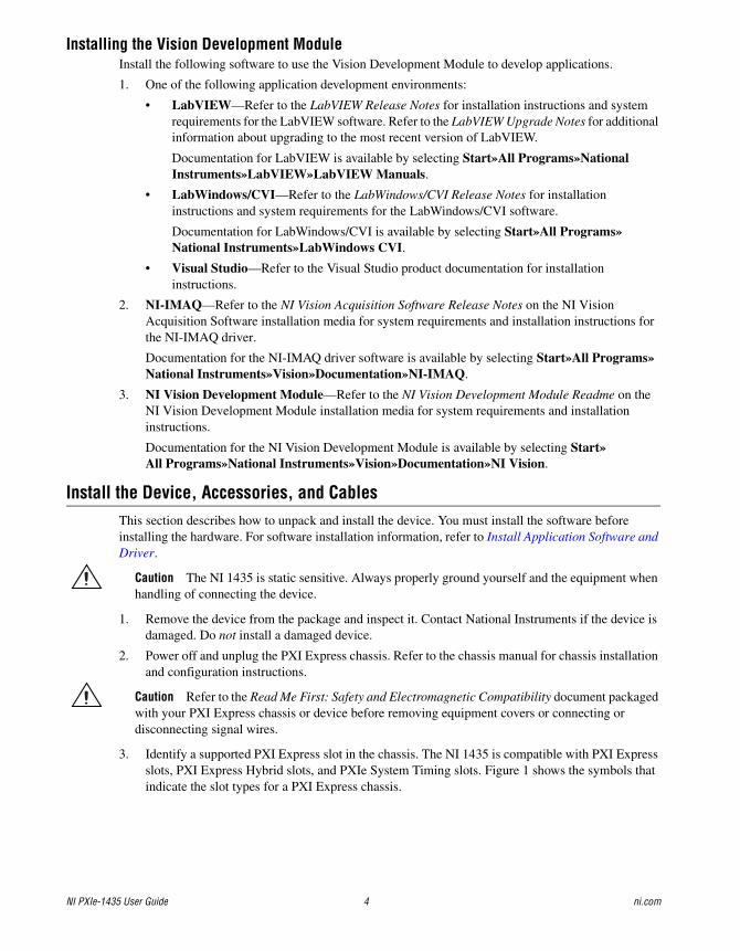
Installing the Vision Development ModuleInstall the following software to use the Vision Development Module to develop applications.
1. One of the following application development environments:
• LabVIEW—Refer to the LabVIEW Release Notes for installation instructions and system requirements for the LabVIEW software. Refer to the LabVIEW Upgrade Notes for additional information about upgrading to the most recent version of LabVIEW.
Documentation for LabVIEW is available by selecting Start»All Programs»National Instruments»LabVIEW»LabVIEW Manuals.
• LabWindows/CVI—Refer to the LabWindows/CVI Release Notes for installation instructions and system requirements for the LabWindows/CVI software.
Documentation for LabWindows/CVI is available by selecting Start»All Programs»National Instruments»LabWindows CVI.
• Visual Studio—Refer to the Visual Studio product documentation for installation instructions.
2. NI-IMAQ—Refer to the NI Vision Acquisition Software Release Notes on the NI Vision Acquisition Software installation media for system requirements and installation instructions for the NI-IMAQ driver.
Documentation for the NI-IMAQ driver software is available by selecting Start»All Programs»National Instruments»Vision»Documentation»NI-IMAQ.
3. NI Vision Development Module—Refer to the NI Vision Development Module Readme on the NI Vision Development Module installation media for system requirements and installation instructions.
Documentation for the NI Vision Development Module is available by selecting Start»All Programs»National Instruments»Vision»Documentation»NI Vision.
Install the Device, Accessories, and CablesThis section describes how to unpack and install the device. You must install the software before installing the hardware. For software installation information, refer to Install Application Software and Driver.
Caution The NI 1435 is static sensitive. Always properly ground yourself and the equipment when handling of connecting the device.
1. Remove the device from the package and inspect it. Contact National Instruments if the device is damaged. Do not install a damaged device.
2. Power off and unplug the PXI Express chassis. Refer to the chassis manual for chassis installation and configuration instructions.
Caution Refer to the Read Me First: Safety and Electromagnetic Compatibility document packaged with your PXI Express chassis or device before removing equipment covers or connecting or disconnecting signal wires.
3. Identify a supported PXI Express slot in the chassis. The NI 1435 is compatible with PXI Express slots, PXI Express Hybrid slots, and PXIe System Timing slots. Figure 1 shows the symbols that indicate the slot types for a PXI Express chassis.
© National Instruments Corporation 5 NI PXIe-1435 User Guide
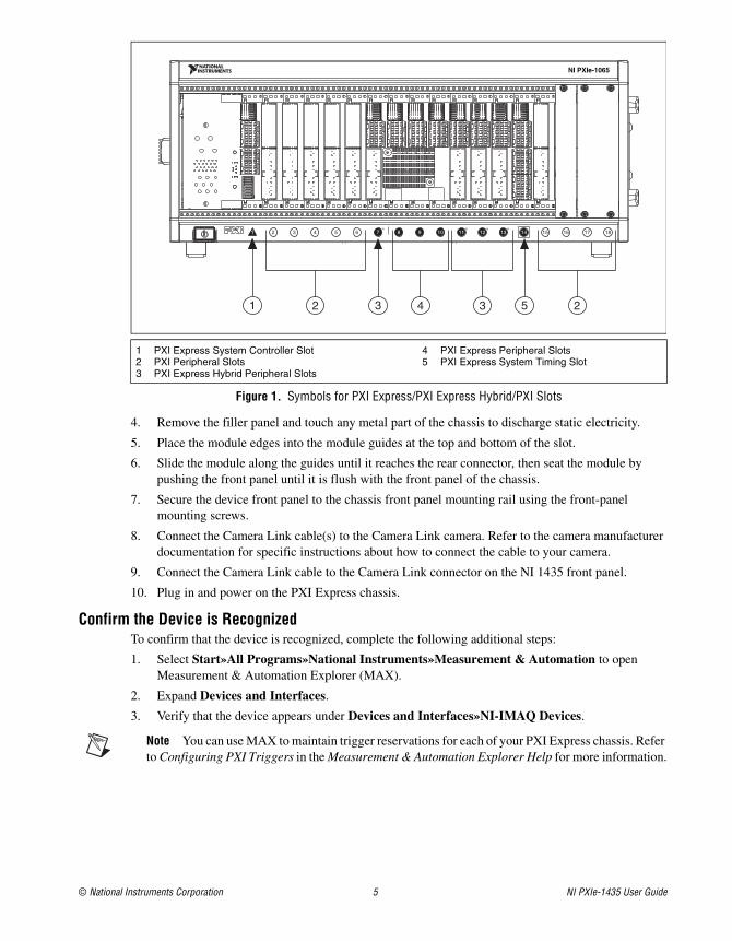
Figure 1. Symbols for PXI Express/PXI Express Hybrid/PXI Slots
4. Remove the filler panel and touch any metal part of the chassis to discharge static electricity.
5. Place the module edges into the module guides at the top and bottom of the slot.
6. Slide the module along the guides until it reaches the rear connector, then seat the module by pushing the front panel until it is flush with the front panel of the chassis.
7. Secure the device front panel to the chassis front panel mounting rail using the front-panel mounting screws.
8. Connect the Camera Link cable(s) to the Camera Link camera. Refer to the camera manufacturer documentation for specific instructions about how to connect the cable to your camera.
9. Connect the Camera Link cable to the Camera Link connector on the NI 1435 front panel.
10. Plug in and power on the PXI Express chassis.
Confirm the Device is RecognizedTo confirm that the device is recognized, complete the following additional steps:
1. Select Start»All Programs»National Instruments»Measurement & Automation to open Measurement & Automation Explorer (MAX).
2. Expand Devices and Interfaces.
3. Verify that the device appears under Devices and Interfaces»NI-IMAQ Devices.
Note You can use MAX to maintain trigger reservations for each of your PXI Express chassis. Refer to Configuring PXI Triggers in the Measurement & Automation Explorer Help for more information.
1 PXI Express System Controller Slot2 PXI Peripheral Slots3 PXI Express Hybrid Peripheral Slots
4 PXI Express Peripheral Slots5 PXI Express System Timing Slot
181716151312111098765432
NI PXIe-1065
3
1H
14H H H
2 234 51
NI PXIe-1435 User Guide 6 ni.com
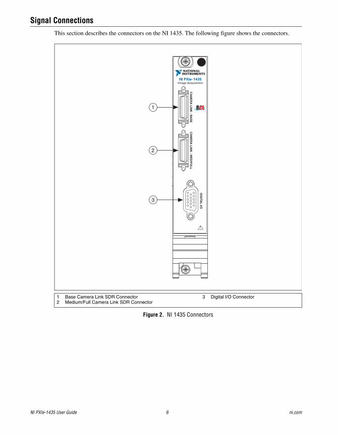
Signal ConnectionsThis section describes the connectors on the NI 1435. The following figure shows the connectors.
Figure 2. NI 1435 Connectors
1 Base Camera Link SDR Connector2 Medium/Full Camera Link SDR Connector
3 Digital I/O Connector
NI PXIe-1435Image Acquisition
CA
ME
RA
LIN
K - B
AS
E
1
3
2C
AM
ER
A L
INK
- ME
D/F
UL
L
!
DIG
ITAL
I/O
© National Instruments Corporation 7 NI PXIe-1435 User Guide
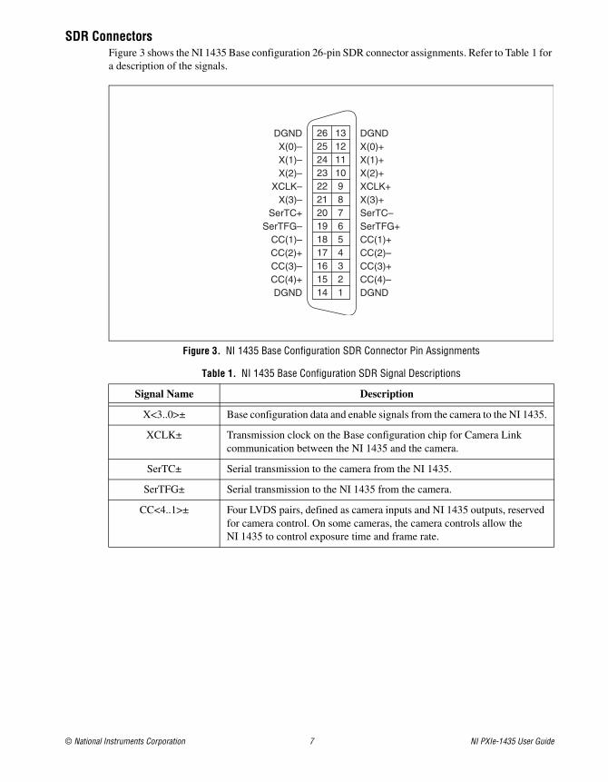
SDR ConnectorsFigure 3 shows the NI 1435 Base configuration 26-pin SDR connector assignments. Refer to Table 1 for a description of the signals.
Figure 3. NI 1435 Base Configuration SDR Connector Pin Assignments
Table 1. NI 1435 Base Configuration SDR Signal Descriptions
Signal Name Description
X<3..0>± Base configuration data and enable signals from the camera to the NI 1435.
XCLK± Transmission clock on the Base configuration chip for Camera Link communication between the NI 1435 and the camera.
SerTC± Serial transmission to the camera from the NI 1435.
SerTFG± Serial transmission to the NI 1435 from the camera.
CC<4..1>± Four LVDS pairs, defined as camera inputs and NI 1435 outputs, reserved for camera control. On some cameras, the camera controls allow the NI 1435 to control exposure time and frame rate.
DGNDX(0)+X(1)+X(2)+XCLK+X(3)+SerTC–SerTFG+CC(1)+CC(2)–CC(3)+CC(4)–DGND
DGNDX(0)–X(1)–X(2)–
XCLK–X(3)–
SerTC+SerTFG–
CC(1)–CC(2)+CC(3)–CC(4)+DGND
13121110987654321
26252423222120191817161514
NI PXIe-1435 User Guide 8 ni.com
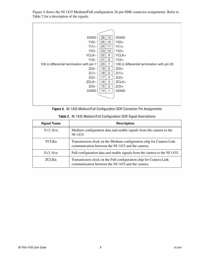
Figure 4 shows the NI 1435 Medium/Full configuration 26-pin SDR connector assignments. Refer to Table 2 for a description of the signals.
Figure 4. NI 1435 Medium/Full Configuration SDR Connector Pin Assignments
Table 2. NI 1435 Medium/Full Configuration SDR Signal Descriptions
Signal Name Description
Y<3..0>± Medium configuration data and enable signals from the camera to the NI 1435.
YCLK± Transmission clock on the Medium configuration chip for Camera Link communication between the NI 1435 and the camera.
Z<3..0>± Full configuration data and enable signals from the camera to the NI 1435.
ZCLK± Transmission clock on the Full configuration chip for Camera Link communication between the NI 1435 and the camera.
DGNDY(0)+Y(1)+Y(2)+YCLK+Y(3)+100 Ω differential termination with pin 20Z(0)+Z(1)+Z(2)+ZCLK+Z(3)+DGND
DGNDY(0)–Y(1)–Y(2)–
YCLK–Y(3)–
100 Ω differential termination with pin 7Z(0)–Z(1)–Z(2)–
ZCLK–Z(3)–
DGND
13121110987654321
26252423222120191817161514
© National Instruments Corporation 9 NI PXIe-1435 User Guide
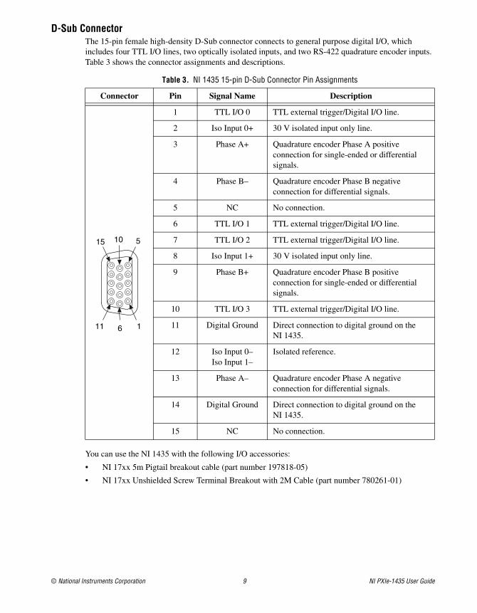
D-Sub ConnectorThe 15-pin female high-density D-Sub connector connects to general purpose digital I/O, which includes four TTL I/O lines, two optically isolated inputs, and two RS-422 quadrature encoder inputs. Table 3 shows the connector assignments and descriptions.
You can use the NI 1435 with the following I/O accessories:
• NI 17xx 5m Pigtail breakout cable (part number 197818-05)
• NI 17xx Unshielded Screw Terminal Breakout with 2M Cable (part number 780261-01)
Table 3. NI 1435 15-pin D-Sub Connector Pin Assignments
Connector Pin Signal Name Description
1 TTL I/O 0 TTL external trigger/Digital I/O line.
2 Iso Input 0+ 30 V isolated input only line.
3 Phase A+ Quadrature encoder Phase A positive connection for single-ended or differential signals.
4 Phase B– Quadrature encoder Phase B negative connection for differential signals.
5 NC No connection.
6 TTL I/O 1 TTL external trigger/Digital I/O line.
7 TTL I/O 2 TTL external trigger/Digital I/O line.
8 Iso Input 1+ 30 V isolated input only line.
9 Phase B+ Quadrature encoder Phase B positive connection for single-ended or differential signals.
10 TTL I/O 3 TTL external trigger/Digital I/O line.
11 Digital Ground Direct connection to digital ground on the NI 1435.
12 Iso Input 0–Iso Input 1–
Isolated reference.
13 Phase A– Quadrature encoder Phase A negative connection for differential signals.
14 Digital Ground Direct connection to digital ground on the NI 1435.
15 NC No connection.
1 6 11
5 10 15
NI PXIe-1435 User Guide 10 ni.com
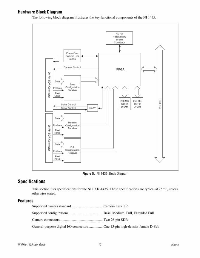
Hardware Block DiagramThe following block diagram illustrates the key functional components of the NI 1435.
Figure 5. NI 1435 Block Diagram
SpecificationsThis section lists specifications for the NI PXIe-1435. These specifications are typical at 25 °C, unless otherwise stated.
FeaturesSupported camera standard....................................Camera Link 1.2
Supported configurations .......................................Base, Medium, Full, Extended Full
Camera connectors.................................................Two 26-pin SDR
General-purpose digital I/O connectors .................One 15-pin high-density female D-Sub
Host B
us
Serial Control
26-Pin S
DR
Connector
26-Pin S
DR
Connector
FullConfiguration
Receiver
Camera Control
UARTSerial Control
PixelClock
Enables
Data
PixelClock
Enables
Data
PixelClock
Enables
Data
15-PinHigh Density
D-SubConnector
FPGA
Power OverCamera Link
Control
256 MBDDR2DRAM
256 MBDDR2DRAM
BaseConfiguration
Receiver
MediumConfiguration
Receiver
© National Instruments Corporation 11 NI PXIe-1435 User Guide
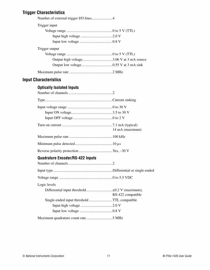
Trigger CharacteristicsNumber of external trigger I/O lines......................4
Trigger input
Voltage range .................................................0 to 5 V (TTL)
Input high voltage ..................................2.0 V
Input low voltage ...................................0.8 V
Trigger output
Voltage range .................................................0 to 5 V (TTL)
Output high voltage................................3.06 V at 3 mA source
Output low voltage.................................0.55 V at 3 mA sink
Maximum pulse rate ..............................................2 MHz
Input Characteristics
Optically Isolated InputsNumber of channels ...............................................2
Type........................................................................Current sinking
Input voltage range ................................................0 to 30 V
Input ON voltage............................................3.5 to 30 V
Input OFF voltage ..........................................0 to 2 V
Turn-on current ......................................................7.1 mA (typical)14 mA (maximum)
Maximum pulse rate ..............................................100 kHz
Minimum pulse detected........................................10 s
Reverse polarity protection ....................................Yes, –30 V
Quadrature Encoder/RS-422 InputsNumber of channels ...............................................2
Input type ...............................................................Differential or single-ended
Voltage range .........................................................0 to 5.5 VDC
Logic levels
Differential input threshold............................±0.2 V (maximum),RS-422 compatible
Single-ended input threshold .........................TTL compatible
Input high voltage ..................................2.0 V
Input low voltage ...................................0.8 V
Maximum quadrature count rate............................5 MHz
NI PXIe-1435 User Guide 12 ni.com
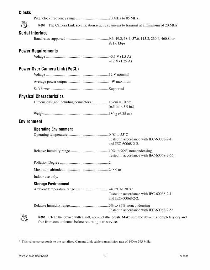
ClocksPixel clock frequency range...................................20 MHz to 85 MHz1
Note The Camera Link specification requires cameras to transmit at a minimum of 20 MHz.
Serial InterfaceBaud rates supported..............................................9.6, 19.2, 38.4, 57.6, 115.2, 230.4, 460.8, or
921.6 kbps
Power RequirementsVoltage ...................................................................+3.3 V (1.5 A)
+12 V (1.25 A)
Power Over Camera Link (PoCL)Voltage ...................................................................12 V nominal
Average power output ............................................4 W maximum
SafePower ..............................................................Supported
Physical CharacteristicsDimensions (not including connectors ..................16 cm × 10 cm
(6.3 in. × 3.9 in.)
Weight ....................................................................180 g (6.35 oz)
Environment
Operating EnvironmentOperating temperature ...........................................0 °C to 55°C
Tested in accordance with IEC-60068-2-1 and IEC-60068-2-2.
Relative humidity range .........................................10% to 90%, noncondensing Tested in accordance with IEC-60068-2-56.
Pollution Degree ....................................................2
Maximum altitude..................................................2,000 m
Indoor use only.
Storage EnvironmentAmbient temperature range ...................................–40 °C to 70 °C
Tested in accordance with IEC-60068-2-1 and IEC-60068-2-2.
Relative humidity range .........................................5% to 95%, noncondensing Tested in accordance with IEC-60068-2-56.
Note Clean the device with a soft, non-metallic brush. Make sure the device is completely dry and free from contaminants before returning it to service.
1 This value corresponds to the serialized Camera Link cable transmission rate of 140 to 595 MHz.
© National Instruments Corporation 13 NI PXIe-1435 User Guide
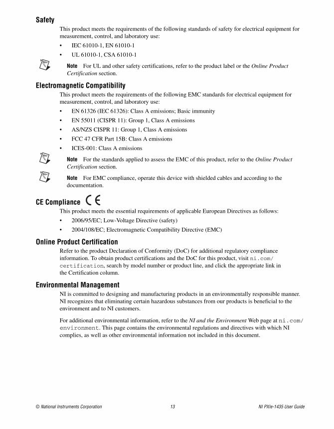
SafetyThis product meets the requirements of the following standards of safety for electrical equipment for measurement, control, and laboratory use:
• IEC 61010-1, EN 61010-1
• UL 61010-1, CSA 61010-1
Note For UL and other safety certifications, refer to the product label or the Online Product Certification section.
Electromagnetic CompatibilityThis product meets the requirements of the following EMC standards for electrical equipment for measurement, control, and laboratory use:
• EN 61326 (IEC 61326): Class A emissions; Basic immunity
• EN 55011 (CISPR 11): Group 1, Class A emissions
• AS/NZS CISPR 11: Group 1, Class A emissions
• FCC 47 CFR Part 15B: Class A emissions
• ICES-001: Class A emissions
Note For the standards applied to assess the EMC of this product, refer to the Online Product Certification section.
Note For EMC compliance, operate this device with shielded cables and according to the documentation.
CE ComplianceThis product meets the essential requirements of applicable European Directives as follows:
• 2006/95/EC; Low-Voltage Directive (safety)
• 2004/108/EC; Electromagnetic Compatibility Directive (EMC)
Online Product CertificationRefer to the product Declaration of Conformity (DoC) for additional regulatory compliance information. To obtain product certifications and the DoC for this product, visit ni.com/certification, search by model number or product line, and click the appropriate link in the Certification column.
Environmental ManagementNI is committed to designing and manufacturing products in an environmentally responsible manner. NI recognizes that eliminating certain hazardous substances from our products is beneficial to the environment and to NI customers.
For additional environmental information, refer to the NI and the Environment Web page at ni.com/environment. This page contains the environmental regulations and directives with which NI complies, as well as other environmental information not included in this document.
NI PXIe-1435 User Guide 14 ni.com
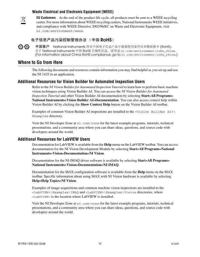
Waste Electrical and Electronic Equipment (WEEE)EU Customers At the end of the product life cycle, all products must be sent to a WEEE recycling center. For more information about WEEE recycling centers, National Instruments WEEE initiatives, and compliance with WEEE Directive 2002/96/EC on Waste and Electronic Equipment, visit ni.com/environment/weee.
Where to Go from HereThe following documents and resources contain information you may find helpful as you set up and use the NI 1435 in an application.
Additional Resources for Vision Builder for Automated Inspection UsersRefer to the NI Vision Builder for Automated Inspection Tutorial to learn how to perform basic machine vision techniques using Vision Builder AI. You can access the NI Vision Builder for Automated Inspection Tutorial and other Vision Builder AI documentation by selecting Start»All Programs»National Instruments»Vision Builder AI»Documentation. You can also access context help within Vision Builder AI by clicking the Show Context Help button on the Vision Builder AI toolbar.
Examples of common Vision Builder AI inspections are installed to the <Vision Builder AI>\Examples directory.
Visit the NI Developer Zone at ni.com/zone for the latest example programs, tutorials, technical presentations, and a community area where you can share ideas, questions, and source code with developers around the world.
Additional Resources for LabVIEW UsersDocumentation for LabVIEW is available from the Help menu on the LabVIEW toolbar. You can access documentation for the NI Vision Development Module by selecting Start»All Programs»National Instruments»Vision»Documentation»NI Vision.
Documentation for the NI-IMAQ driver software is available by selecting Start»All Programs»National Instruments»Vision»Documentation»NI-IMAQ.
Documentation for the MAX configuration software is available from the Help menu on the MAX toolbar. Specific information about using MAX with NI Vision hardware is available by selecting Help»Help Topics»NI Vision.
Examples of image acquisitions and common machine vision inspections are installed to the <LabVIEW>\Examples\IMAQ and <LabVIEW>\Examples\Vision directories, where <LabVIEW> is the location where LabVIEW is installed.
Visit the NI Developer Zone at ni.com/zone for the latest example programs, tutorials, technical presentations, and a community area where you can share ideas, questions, and source code with developers around the world.
RoHSNational Instruments (RoHS)
National Instruments RoHS ni.com/environment/rohs_china(For information about China RoHS compliance, go to ni.com/environment/rohs_china.)
© National Instruments Corporation 15 NI PXIe-1435 User Guide
Where to Go for SupportThe National Instruments Web site is your complete resource for technical support. At ni.com/support you have access to everything from troubleshooting and application development self-help resources to email and phone assistance from NI Application Engineers.
A Declaration of Conformity (DoC) is our claim of compliance with the Council of the European Communities using the manufacturer’s declaration of conformity. This system affords the user protection for electromagnetic compatibility (EMC) and product safety. You can obtain the DoC for your product by visiting ni.com/certification. If your product supports calibration, you can obtain the calibration certificate for your product at ni.com/calibration.
National Instruments corporate headquarters is located at 11500 North Mopac Expressway, Austin, Texas, 78759-3504. National Instruments also has offices located around the world to help address your support needs. For telephone support in the United States, create your service request at ni.com/support and follow the calling instructions or dial 512 795 8248. For telephone support outside the United States, visit the Worldwide Offices section of ni.com/niglobal to access the branch office Web sites, which provide up-to-date contact information, support phone numbers, email addresses, and current events.

CVI, LabVIEW, National Instruments, NI, ni.com, the National Instruments corporate logo, and the Eagle logo are trademarks of National Instruments Corporation. Refer to the Trademark Information at ni.com/trademarks for other National Instruments trademarks. The mark LabWindows is used under a license from Microsoft Corporation. Windows is a registered trademark of Microsoft Corporation in the United States and other countries. Other product and company names mentioned herein are trademarks or trade names of their respective companies. For patents covering National Instruments products/technology, refer to the appropriate location: Help»Patents in your software, the patents.txt file on your media, or the National Instruments Patent Notice at ni.com/patents. Refer to the Export Compliance Information at ni.com/legal/export-compliance for the National Instruments global trade compliance policy.
© 2011 National Instruments Corporation. All rights reserved. 375691A-01 Apr11