NI 9213 Datasheet - National Instruments measurement range ±78.125 mV Temperature measurement...
14
DATASHEET NI 9213 16 TC, ±78 mV, 24 Bit, 75 S/s Aggregate • Spring-terminal connectivity • 50 Hz/60 Hz noise rejection • Up to 0.02 °C measurement sensitivity • 250 Vrms, CAT II, channel-to-earth isolation The NI 9213 is a high-density thermocouple module for CompactDAQ and CompactRIO chassis. Designed for higher-channel-count systems, the NI 9213 adds thermocouples to mixed-signal test systems without taking up too many slots. Kit Contents Accessories • • NI 9213 NI 9213 Getting Started Guide • NI 9940 Backshell Connector Kit
Transcript of NI 9213 Datasheet - National Instruments measurement range ±78.125 mV Temperature measurement...
DATASHEET
NI 921316 TC, ±78 mV, 24 Bit, 75 S/s Aggregate
• Spring-terminal connectivity• 50 Hz/60 Hz noise rejection• Up to 0.02 °C measurement sensitivity• 250 Vrms, CAT II, channel-to-earth
isolation
The NI 9213 is a high-density thermocouple module for CompactDAQ and CompactRIOchassis. Designed for higher-channel-count systems, the NI 9213 adds thermocouples tomixed-signal test systems without taking up too many slots.
Kit Contents
Accessories
•• NI 9213 NI 9213 Getting Started Guide
• NI 9940 Backshell Connector Kit
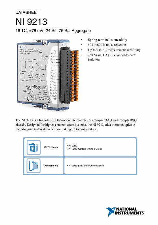
NI C Series Overview
NI provides more than 100 C Series modules for measurement, control, and communicationapplications. C Series modules can connect to any sensor or bus and allow for high-accuracymeasurements that meet the demands of advanced data acquisition and control applications.• Measurement-specific signal conditioning that connects to an array of sensors and signals• Isolation options such as bank-to-bank, channel-to-channel, and channel-to-earth ground• -40 °C to 70 °C temperature range to meet a variety of application and environmental
needs• Hot-swappable
The majority of C Series modules are supported in both CompactRIO and CompactDAQplatforms and you can move modules from one platform to the other with no modification.
CompactRIO
CompactRIO combines an open-embedded architecturewith small size, extreme ruggedness, and C Seriesmodules in a platform powered by the NI LabVIEWreconfigurable I/O (RIO) architecture. Each systemcontains an FPGA for custom timing, triggering, andprocessing with a wide array of available modular I/O tomeet any embedded application requirement.
CompactDAQ
CompactDAQ is a portable, rugged data acquisition platformthat integrates connectivity, data acquisition, and signalconditioning into modular I/O for directly interfacing to anysensor or signal. Using CompactDAQ with LabVIEW, youcan easily customize how you acquire, analyze, visualize, andmanage your measurement data.
2 | ni.com | NI 9213 Datasheet
Software
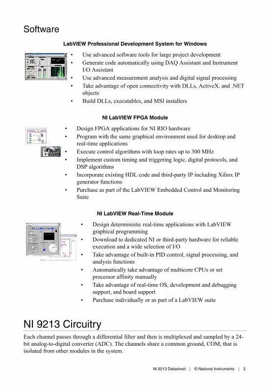
LabVIEW Professional Development System for Windows
• Use advanced software tools for large project development• Generate code automatically using DAQ Assistant and Instrument
I/O Assistant• Use advanced measurement analysis and digital signal processing• Take advantage of open connectivity with DLLs, ActiveX, and .NET
objects• Build DLLs, executables, and MSI installers
NI LabVIEW FPGA Module
• Design FPGA applications for NI RIO hardware• Program with the same graphical environment used for desktop and
real-time applications• Execute control algorithms with loop rates up to 300 MHz• Implement custom timing and triggering logic, digital protocols, and
DSP algorithms• Incorporate existing HDL code and third-party IP including Xilinx IP
generator functions• Purchase as part of the LabVIEW Embedded Control and Monitoring
Suite
NI LabVIEW Real-Time Module
• Design deterministic real-time applications with LabVIEWgraphical programming
• Download to dedicated NI or third-party hardware for reliableexecution and a wide selection of I/O
• Take advantage of built-in PID control, signal processing, andanalysis functions
• Automatically take advantage of multicore CPUs or setprocessor affinity manually
• Take advantage of real-time OS, development and debuggingsupport, and board support
• Purchase individually or as part of a LabVIEW suite
NI 9213 CircuitryEach channel passes through a differential filter and then is multiplexed and sampled by a 24-bit analog-to-digital converter (ADC). The channels share a common ground, COM, that isisolated from other modules in the system.
NI 9213 Datasheet | © National Instruments | 3
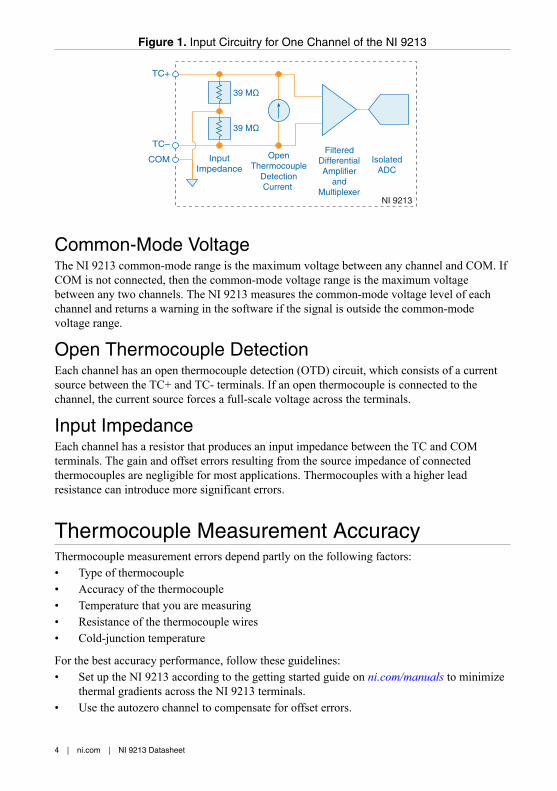
Figure 1. Input Circuitry for One Channel of the NI 9213
TC+
TC–
COM
NI 9213
InputImpedance
OpenThermocouple
DetectionCurrent
FilteredDifferentialAmplifier
andMultiplexer
IsolatedADC
39 MΩ
39 MΩ
Common-Mode VoltageThe NI 9213 common-mode range is the maximum voltage between any channel and COM. IfCOM is not connected, then the common-mode voltage range is the maximum voltagebetween any two channels. The NI 9213 measures the common-mode voltage level of eachchannel and returns a warning in the software if the signal is outside the common-modevoltage range.
Open Thermocouple DetectionEach channel has an open thermocouple detection (OTD) circuit, which consists of a currentsource between the TC+ and TC- terminals. If an open thermocouple is connected to thechannel, the current source forces a full-scale voltage across the terminals.
Input ImpedanceEach channel has a resistor that produces an input impedance between the TC and COMterminals. The gain and offset errors resulting from the source impedance of connectedthermocouples are negligible for most applications. Thermocouples with a higher leadresistance can introduce more significant errors.
Thermocouple Measurement AccuracyThermocouple measurement errors depend partly on the following factors:• Type of thermocouple• Accuracy of the thermocouple• Temperature that you are measuring• Resistance of the thermocouple wires• Cold-junction temperature
For the best accuracy performance, follow these guidelines:• Set up the NI 9213 according to the getting started guide on ni.com/manuals to minimize
thermal gradients across the NI 9213 terminals.• Use the autozero channel to compensate for offset errors.
4 | ni.com | NI 9213 Datasheet
Cold-Junction AccuracyHeat dissipated by adjacent C Series modules or nearby heat sources can cause errors inthermocouple measurements by heating the NI 9213 terminals to a different temperature thanthe cold-junction compensation sensor. Thermal gradient across the terminals can cause theterminals of different NI 9213 channels to be at different temperatures, which creates accuracyerrors and affects the relative accuracy between channels.
The temperature measurement accuracy specifications include errors caused by the thermalgradient across the NI 9213 terminals for configurations with the NI 9213 terminals facingforward or upward.
Autozero ChannelThe NI 9213 has an internal autozero channel, which can be subtracted from eachthermocouple reading to compensate for offset errors. Use of the autozero channel is optional,however the NI 9213 specifications assume that autozero is applied to every sample. Refer tothe documentation for the software that you are using with the NI 9213 for information aboutusing the autozero channel.
Timing ModesThe NI 9213 supports high-resolution and high-speed timing modes. High-resolution timingmode optimizes accuracy and noise and rejects power line frequencies. High-speed timingmode optimizes sample rate and signal bandwidth.
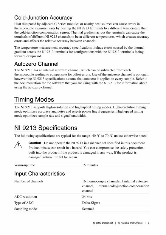
NI 9213 SpecificationsThe following specifications are typical for the range -40 °C to 70 °C unless otherwise noted.
Caution Do not operate the NI 9213 in a manner not specified in this document.Product misuse can result in a hazard. You can compromise the safety protectionbuilt into the product if the product is damaged in any way. If the product isdamaged, return it to NI for repair.
Warm-up time 15 minutes
Input CharacteristicsNumber of channels 16 thermocouple channels, 1 internal autozero
channel, 1 internal cold-junction compensationchannel
ADC resolution 24 bits
Type of ADC Delta-Sigma
Sampling mode Scanned
NI 9213 Datasheet | © National Instruments | 5
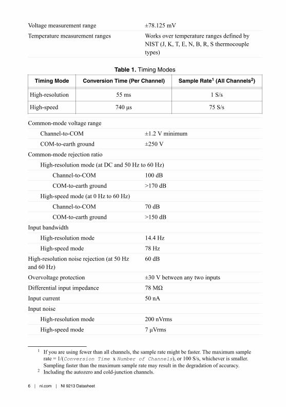
Voltage measurement range ±78.125 mV
Temperature measurement ranges Works over temperature ranges defined byNIST (J, K, T, E, N, B, R, S thermocoupletypes)
Table 1. Timing Modes
Timing Mode Conversion Time (Per Channel) Sample Rate1 (All Channels2)
High-resolution 55 ms 1 S/s
High-speed 740 μs 75 S/s
Common-mode voltage range
Channel-to-COM ±1.2 V minimum
COM-to-earth ground ±250 V
Common-mode rejection ratio
High-resolution mode (at DC and 50 Hz to 60 Hz)
Channel-to-COM 100 dB
COM-to-earth ground >170 dB
High-speed mode (at 0 Hz to 60 Hz)
Channel-to-COM 70 dB
COM-to-earth ground >150 dB
Input bandwidth
High-resolution mode 14.4 Hz
High-speed mode 78 Hz
High-resolution noise rejection (at 50 Hzand 60 Hz)
60 dB
Overvoltage protection ±30 V between any two inputs
Differential input impedance 78 MΩ
Input current 50 nA
Input noise
High-resolution mode 200 nVrms
High-speed mode 7 μVrms
1 If you are using fewer than all channels, the sample rate might be faster. The maximum samplerate = 1/(Conversion Time x Number of Channels), or 100 S/s, whichever is smaller.Sampling faster than the maximum sample rate may result in the degradation of accuracy.
2 Including the autozero and cold-junction channels.
6 | ni.com | NI 9213 Datasheet
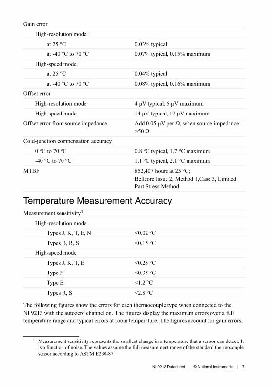
Gain error
High-resolution mode
at 25 °C 0.03% typical
at -40 °C to 70 °C 0.07% typical, 0.15% maximum
High-speed mode
at 25 °C 0.04% typical
at -40 °C to 70 °C 0.08% typical, 0.16% maximum
Offset error
High-resolution mode 4 μV typical, 6 μV maximum
High-speed mode 14 μV typical, 17 μV maximum
Offset error from source impedance Add 0.05 μV per Ω, when source impedance>50 Ω
Cold-junction compensation accuracy
0 °C to 70 °C 0.8 °C typical, 1.7 °C maximum
-40 °C to 70 °C 1.1 °C typical, 2.1 °C maximum
MTBF 852,407 hours at 25 °C;Bellcore Issue 2, Method 1,Case 3, LimitedPart Stress Method
Temperature Measurement AccuracyMeasurement sensitivity3
High-resolution mode
Types J, K, T, E, N <0.02 °C
Types B, R, S <0.15 °C
High-speed mode
Types J, K, T, E <0.25 °C
Type N <0.35 °C
Type B <1.2 °C
Types R, S <2.8 °C
The following figures show the errors for each thermocouple type when connected to theNI 9213 with the autozero channel on. The figures display the maximum errors over a fulltemperature range and typical errors at room temperature. The figures account for gain errors,
3 Measurement sensitivity represents the smallest change in a temperature that a sensor can detect. Itis a function of noise. The values assume the full measurement range of the standard thermocouplesensor according to ASTM E230-87.
NI 9213 Datasheet | © National Instruments | 7
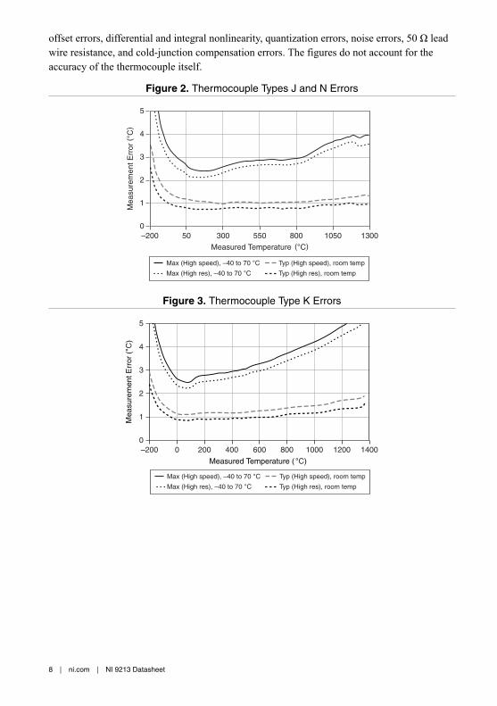
offset errors, differential and integral nonlinearity, quantization errors, noise errors, 50 Ω leadwire resistance, and cold-junction compensation errors. The figures do not account for theaccuracy of the thermocouple itself.
Figure 2. Thermocouple Types J and N Errors
Measured Temperature (°C)
Mea
sure
men
t Err
or (
°C)
0
1
3
4
5
2
–200 50 300 550 800 1050 1300
Max (High speed), –40 to 70 °CMax (High res), –40 to 70 °C Typ (High res), room temp
Typ (High speed), room temp
Figure 3. Thermocouple Type K Errors
Measured Temperature ( °C)
Mea
sure
men
t Err
or (
°C)
0
1
4
5
3
2
–200 0 200 400 600 800 1000 1200 1400
Max (High speed), –40 to 70 °CMax (High res), –40 to 70 °C Typ (High res), room temp
Typ (High speed), room temp
8 | ni.com | NI 9213 Datasheet
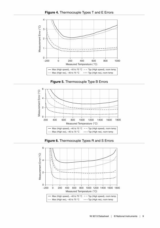
Figure 4. Thermocouple Types T and E Errors
Measured Temperature ( °C)
Mea
sure
men
t Err
or (
°C)
Max (High speed), –40 to 70 °CMax (High res), –40 to 70 °C Typ (High res), room temp
Typ (High speed), room temp
0
1
3
4
2
–200 0 200 400 600 800 1000
Figure 5. Thermocouple Type B Errors
Measured Temperature (°C)
Mea
sure
men
t Err
or (
°C)
0
2
6
4
200 400 600 800 1000 1200 1400 1600 1800
Max (High speed), –40 to 70 °CMax (High res), –40 to 70 °C Typ (High res), room temp
Typ (High speed), room temp
Figure 6. Thermocouple Types R and S Errors
Measured Temperature (°C)
Mea
sure
men
t Err
or (
°C)
0
2
6
4
–200 0 200 400 600 800 1000 1200 1400 1600 1800
Max (High speed), –40 to 70 °CMax (High res), –40 to 70 °C Typ (High res), room temp
Typ (High speed), room temp
NI 9213 Datasheet | © National Instruments | 9
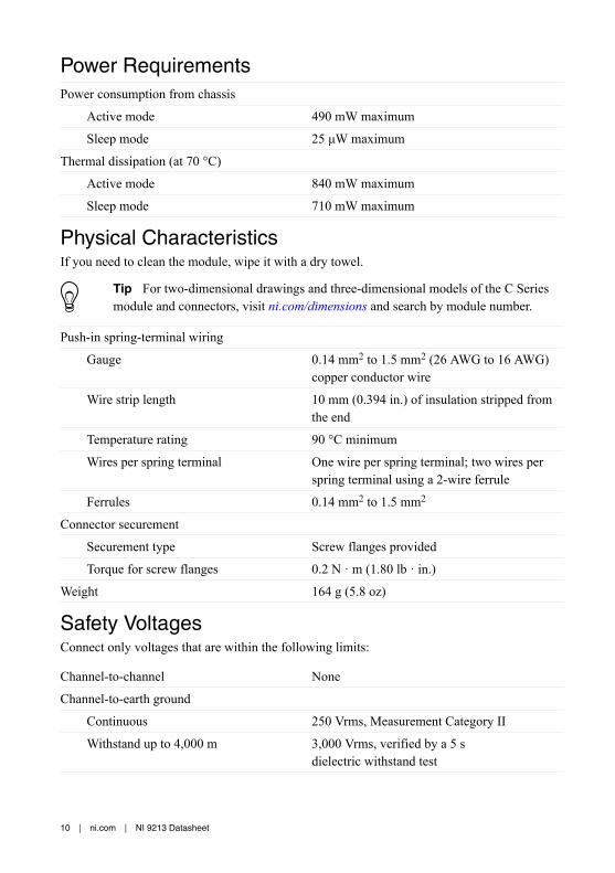
Power RequirementsPower consumption from chassis
Active mode 490 mW maximum
Sleep mode 25 μW maximum
Thermal dissipation (at 70 °C)
Active mode 840 mW maximum
Sleep mode 710 mW maximum
Physical CharacteristicsIf you need to clean the module, wipe it with a dry towel.
Tip For two-dimensional drawings and three-dimensional models of the C Seriesmodule and connectors, visit ni.com/dimensions and search by module number.
Push-in spring-terminal wiring
Gauge 0.14 mm2 to 1.5 mm2 (26 AWG to 16 AWG)copper conductor wire
Wire strip length 10 mm (0.394 in.) of insulation stripped fromthe end
Temperature rating 90 °C minimum
Wires per spring terminal One wire per spring terminal; two wires perspring terminal using a 2-wire ferrule
Ferrules 0.14 mm2 to 1.5 mm2
Connector securement
Securement type Screw flanges provided
Torque for screw flanges 0.2 N · m (1.80 lb · in.)
Weight 164 g (5.8 oz)
Safety VoltagesConnect only voltages that are within the following limits:
Channel-to-channel None
Channel-to-earth ground
Continuous 250 Vrms, Measurement Category II
Withstand up to 4,000 m 3,000 Vrms, verified by a 5 sdielectric withstand test
10 | ni.com | NI 9213 Datasheet
Measurement Category II is for measurements performed on circuits directly connected to theelectrical distribution system. This category refers to local-level electrical distribution, such asthat provided by a standard wall outlet, for example, 115 V for U.S. or 230 V for Europe.
Caution Do not connect the NI 9213 to signals or use for measurements withinMeasurement Categories III or IV.
Hazardous LocationsU.S. (UL) Class I, Division 2, Groups A, B, C, D, T4;
Class I, Zone 2, AEx nA IIC T4
Canada (C-UL) Class I, Division 2, Groups A, B, C, D, T4;Class I, Zone 2, Ex nA IIC T4
Europe (ATEX) and International (IECEx) Ex nA IIC T4 Gc
Safety and Hazardous Locations StandardsThis product is designed to meet the requirements of the following electrical equipment safetystandards for measurement, control, and laboratory use:• IEC 61010-1, EN 61010-1• UL 61010-1, CSA 61010-1• EN 60079-0:2012, EN 60079-15:2010• IEC 60079-0: Ed 6, IEC 60079-15; Ed 4• UL 60079-0; Ed 6, UL 60079-15; Ed 4• CSA 60079-0:2011, CSA 60079-15:2012
Note For UL and other safety certifications, refer to the product label or the OnlineProduct Certification section.
CE Compliance This product meets the essential requirements of applicable European Directives, as follows:• 2014/35/EU; Low-Voltage Directive (safety)• 2014/30/EU; Electromagnetic Compatibility Directive (EMC)• 2014/34/EU; Potentially Explosive Atmospheres (ATEX)
Electromagnetic CompatibilityThis product meets the requirements of the following EMC standards for electrical equipmentfor measurement, control, and laboratory use:• EN 61326-1 (IEC 61326-1): Class A emissions; Industrial immunity• EN 55011 (CISPR 11): Group 1, Class A emissions• EN 55022 (CISPR 22): Class A emissions• EN 55024 (CISPR 24): Immunity
NI 9213 Datasheet | © National Instruments | 11
• AS/NZS CISPR 11: Group 1, Class A emissions• AS/NZS CISPR 22: Class A emissions• FCC 47 CFR Part 15B: Class A emissions• ICES-001: Class A emissions
Note In the United States (per FCC 47 CFR), Class A equipment is intended foruse in commercial, light-industrial, and heavy-industrial locations. In Europe,Canada, Australia and New Zealand (per CISPR 11) Class A equipment is intendedfor use only in heavy-industrial locations.
Note Group 1 equipment (per CISPR 11) is any industrial, scientific, or medicalequipment that does not intentionally generate radio frequency energy for thetreatment of material or inspection/analysis purposes.
Note For EMC declarations and certifications, and additional information, refer tothe Online Product Certification section.
Online Product CertificationRefer to the product Declaration of Conformity (DoC) for additional regulatory complianceinformation. To obtain product certifications and the DoC for this product, visit ni.com/certification, search by model number or product line, and click the appropriate link in theCertification column.
Shock and VibrationTo meet these specifications, you must panel mount the system.
Operating vibration
Random (IEC 60068-2-64) 5 grms, 10 Hz to 500 Hz
Sinusoidal (IEC 60068-2-6) 5 g, 10 Hz to 500 Hz
Operating shock (IEC 60068-2-27) 30 g, 11 ms half sine; 50 g, 3 ms half sine;18 shocks at 6 orientations
EnvironmentalRefer to the manual for the chassis you are using for more information about meeting thesespecifications.
Operating temperature(IEC 60068-2-1, IEC 60068-2-2)
-40 °C to 70 °C
Storage temperature(IEC 60068-2-1, IEC 60068-2-2)
-40 °C to 85 °C
Ingress protection IP40
Operating humidity (IEC 60068-2-78) 10% RH to 90% RH, noncondensing
12 | ni.com | NI 9213 Datasheet

Storage humidity (IEC 60068-2-78) 5% RH to 95% RH, noncondensing
Pollution Degree 2
Maximum altitude 4,000 m
Indoor use only.
Environmental ManagementNI is committed to designing and manufacturing products in an environmentally responsiblemanner. NI recognizes that eliminating certain hazardous substances from our products isbeneficial to the environment and to NI customers.
For additional environmental information, refer to the Minimize Our Environmental Impactweb page at ni.com/environment. This page contains the environmental regulations anddirectives with which NI complies, as well as other environmental information not included inthis document.
Waste Electrical and Electronic Equipment (WEEE)EU Customers At the end of the product life cycle, all NI products must bedisposed of according to local laws and regulations. For more information abouthow to recycle NI products in your region, visit ni.com/environment/weee.
电子信息产品污染控制管理办法(中国 RoHS)中国客户 National Instruments 符合中国电子信息产品中限制使用某些有害物
质指令(RoHS)。关于 National Instruments 中国 RoHS 合规性信息,请登录
ni.com/environment/rohs_china。(For information about China RoHScompliance, go to ni.com/environment/rohs_china.)
CalibrationYou can obtain the calibration certificate and information about calibration services for theNI 9213 at ni.com/calibration.
Calibration interval 1 year
NI 9213 Datasheet | © National Instruments | 13

Refer to the NI Trademarks and Logo Guidelines at ni.com/trademarks for information on NI trademarks. Other product andcompany names mentioned herein are trademarks or trade names of their respective companies. For patents covering NIproducts/technology, refer to the appropriate location: Help»Patents in your software, the patents.txt file on your media, or theNational Instruments Patent Notice at ni.com/patents. You can find information about end-user license agreements (EULAs)and third-party legal notices in the readme file for your NI product. Refer to the Export Compliance Information at ni.com/legal/export-compliance for the NI global trade compliance policy and how to obtain relevant HTS codes, ECCNs, and otherimport/export data. NI MAKES NO EXPRESS OR IMPLIED WARRANTIES AS TO THE ACCURACY OF THE INFORMATIONCONTAINED HEREIN AND SHALL NOT BE LIABLE FOR ANY ERRORS. U.S. Government Customers: The data contained inthis manual was developed at private expense and is subject to the applicable limited rights and restricted data rights as set forthin FAR 52.227-14, DFAR 252.227-7014, and DFAR 252.227-7015.
© 2017 National Instruments. All rights reserved.
378021A-02 Jan17