NI 9211 Operating Instructions and...
39
OPERATING INSTRUCTIONS AND SPECIFICATIONS NI 9211 4-Channel Thermocouple Input Module ni.com/manuals Deutsch Français
Transcript of NI 9211 Operating Instructions and...

OPERATING INSTRUCTIONS AND SPECIFICATIONS
NI 92114-Channel Thermocouple Input Module
ni.com/manuals
DeutschFrançais
NI 9211 Operating Instructions and Specifications 2 ni.com
This document describes how to use the National Instruments 9211 and includes specifications and terminal assignments for the NI 9211. Visit ni.com/info and enter rdsoftwareversion to determine which software you need for the modules you are using. For information about installing, configuring, and programming the system, refer to the system documentation. Visit ni.com/info and enter cseriesdoc for information about C Series documentation.
Note The safety guidelines and specifications in this document are specific to the NI 9211. The other components in the system might not meet the same safety ratings and specifications. Refer to the documentation for each component in the system to determine the safety ratings and specifications for the entire system. Visit ni.com/info and enter cseriesdoc for information about C Series documentation.
Safety GuidelinesOperate the NI 9211 only as described in these operating instructions.
Hot Surface This icon denotes that the component may be hot. Touching this component may result in bodily injury.

© National Instruments Corp. 3 NI 9211 Operating Instructions and Specifications
Safety Guidelines for Hazardous VoltagesIf hazardous voltages are connected to the module, take the following precautions. A hazardous voltage is a voltage greater than 42.4 Vpk or 60 VDC to earth ground.
Caution Ensure that hazardous voltage wiring is performed only by qualified personnel adhering to local electrical standards.
Caution Do not mix hazardous voltage circuits and human-accessible circuits on the same module.
Caution Make sure that devices and circuits connected to the module are properly insulated from human contact.
Caution When module terminals are hazardous voltage LIVE (>42.4 Vpk/60 VDC), you must ensure that devices and circuits connected to the module are properly insulated from human contact. You must use the NI 9932 connector backshell kit to ensure that the terminals are not accessible.
NI 9211 Operating Instructions and Specifications 4 ni.com
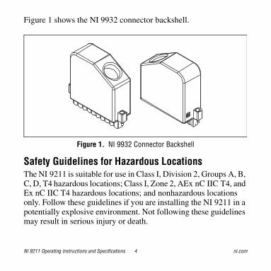
Figure 1 shows the NI 9932 connector backshell.
Figure 1. NI 9932 Connector Backshell
Safety Guidelines for Hazardous LocationsThe NI 9211 is suitable for use in Class I, Division 2, Groups A, B, C, D, T4 hazardous locations; Class I, Zone 2, AEx nC IIC T4, and Ex nC IIC T4 hazardous locations; and nonhazardous locations only. Follow these guidelines if you are installing the NI 9211 in a potentially explosive environment. Not following these guidelines may result in serious injury or death.
© National Instruments Corp. 5 NI 9211 Operating Instructions and Specifications
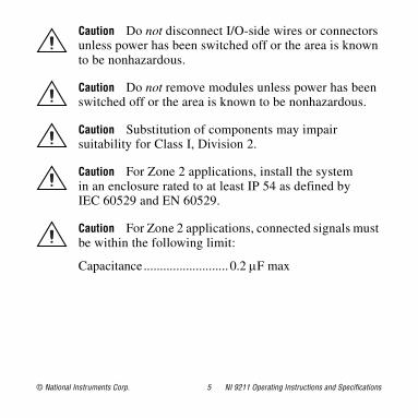
Caution Do not disconnect I/O-side wires or connectors unless power has been switched off or the area is known to be nonhazardous.
Caution Do not remove modules unless power has been switched off or the area is known to be nonhazardous.
Caution Substitution of components may impair suitability for Class I, Division 2.
Caution For Zone 2 applications, install the system in an enclosure rated to at least IP 54 as defined by IEC 60529 and EN 60529.
Caution For Zone 2 applications, connected signals must be within the following limit:
Capacitance.......................... 0.2 F max
NI 9211 Operating Instructions and Specifications 6 ni.com
Special Conditions for Hazardous Locations Use in EuropeThis equipment has been evaluated as Ex nC IIC T4 equipment under DEMKO Certificate No. 03 ATEX 0324020X. Each module is marked II 3G and is suitable for use in Zone 2 hazardous locations, in ambient temperatures of –40 °C Ta 70 °C. If you are using the NI 9211 in Gas Group IIC hazardous locations, you must use the device in an NI chassis that has been evaluated as Ex nC IIC T4, EEx nC IIC T4, Ex nA IIC T4, or Ex nL IIC T4 equipment.
© National Instruments Corp. 7 NI 9211 Operating Instructions and Specifications
Electromagnetic Compatibility GuidelinesThis product was tested and complies with the regulatory requirements and limits for electromagnetic compatibility (EMC) as stated in the product specifications. These requirements and limits are designed to provide reasonable protection against harmful interference when the product is operated in its intended operational electromagnetic environment. There is no guarantee that interference will not occur in a particular installation. To minimize the potential for the product to cause interference to radio and television reception or to experience unacceptable performance degradation, install and use this product in strict accordance with the instructions in the product documentation.
The following statements contain important information needed before installing and using this product:
Caution This product is intended for use in industrial locations. As a result, this product may cause interference if used in residential areas. Such use must be avoided unless the user takes special measures to reduce electromagnetic emissions to prevent interference to the reception of radio and television broadcasts.
NI 9211 Operating Instructions and Specifications 8 ni.com
Caution Emissions that exceed the regulatory requirements may occur when this product is connected to a test object.
Caution Changes or modifications not expressly approved by National Instruments could void the user’s authority to operate the hardware under the local regulatory rules.
Special Guidelines for Marine ApplicationsSome products are Lloyd’s Register (LR) Type Approved for marine (shipboard) applications. To verify Lloyd’s Register certification for a product, visit ni.com/certification and search for the LR certificate, or look for the Lloyd’s Register mark on the product label.
Caution In order to meet the EMC requirements for marine applications, install the product in a shielded enclosure with shielded and/or filtered power and input/output ports. In addition, take precautions when designing, selecting, and installing measurement probes and cables to ensure that the desired EMC performance is attained.
© National Instruments Corp. 9 NI 9211 Operating Instructions and Specifications
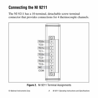
Connecting the NI 9211The NI 9211 has a 10-terminal, detachable screw-terminal connector that provides connections for 4 thermocouple channels.
Figure 2. NI 9211 Terminal Assignments
TC0+TC0–TC1+TC1–TC2+TC2–TC3+TC3–NCCOM
0123456789
NI 9211 Operating Instructions and Specifications 10 ni.com
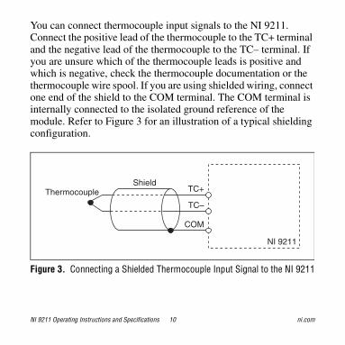
You can connect thermocouple input signals to the NI 9211. Connect the positive lead of the thermocouple to the TC+ terminal and the negative lead of the thermocouple to the TC– terminal. If you are unsure which of the thermocouple leads is positive and which is negative, check the thermocouple documentation or the thermocouple wire spool. If you are using shielded wiring, connect one end of the shield to the COM terminal. The COM terminal is internally connected to the isolated ground reference of the module. Refer to Figure 3 for an illustration of a typical shielding configuration.
Figure 3. Connecting a Shielded Thermocouple Input Signal to the NI 9211
TC–
TC+Shield
NI 9211
COM
Thermocouple
© National Instruments Corp. 11 NI 9211 Operating Instructions and Specifications
Note You must use 2-wire ferrules to create a secure connection when connecting more than one wire to a single terminal on the NI 9211.
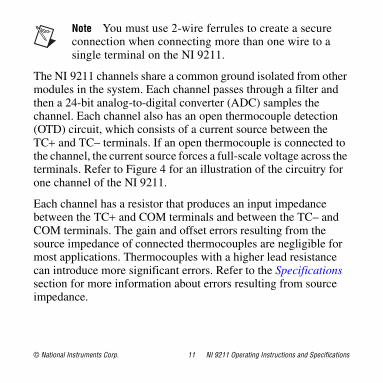
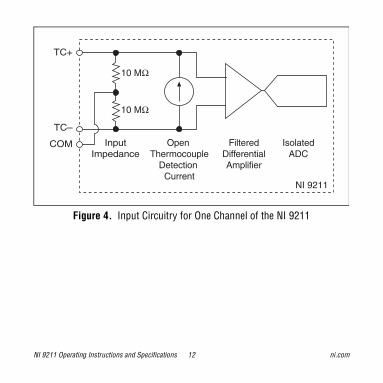
The NI 9211 channels share a common ground isolated from other modules in the system. Each channel passes through a filter and then a 24-bit analog-to-digital converter (ADC) samples the channel. Each channel also has an open thermocouple detection (OTD) circuit, which consists of a current source between the TC and TC– terminals. If an open thermocouple is connected to the channel, the current source forces a full-scale voltage across the terminals. Refer to Figure 4 for an illustration of the circuitry for one channel of the NI 9211.
Each channel has a resistor that produces an input impedance between the TC and COM terminals and between the TC– and COM terminals. The gain and offset errors resulting from the source impedance of connected thermocouples are negligible for most applications. Thermocouples with a higher lead resistance can introduce more significant errors. Refer to the Specifications section for more information about errors resulting from source impedance.
NI 9211 Operating Instructions and Specifications 12 ni.com
Figure 4. Input Circuitry for One Channel of the NI 9211
TC+
TC–
COM
NI 9211
InputImpedance
Open Thermocouple
Detection Current
FilteredDifferentialAmplifier
IsolatedADC
10 MΩ
10 MΩ

© National Instruments Corp. 13 NI 9211 Operating Instructions and Specifications
Wiring for High-Vibration ApplicationsIf an application is subject to high vibration, National Instruments recommends that you either use ferrules to terminate wires to the detachable screw-terminal connector or use the NI 9932 backshell kit to protect the connections. Refer to Figure 5 for an illustration of using ferrules. Refer to Figure 1 for an illustration of the NI 9932 connector backshell.
Figure 5. 10-Terminal Detachable Screw-Terminal Connector with Ferrule
NI 9211 Operating Instructions and Specifications 14 ni.com
Temperature Measurement Accuracy ConsiderationsTemperature measurement errors depend partly on the thermocouple type, the accuracy of the thermocouple, the temperature being measured, and the cold-junction temperature. Refer to the Temperature Measurement Accuracy section in the Specifications for the errors of each thermocouple type when connected to the NI 9211. The errors do not account for the accuracy of the thermocouple itself.
For the best accuracy results, keep temperature gradients across NI 9211 terminals to a minimum. Refer to the Minimizing Thermal Gradients section for more information.
Cold-Junction Temperature Measurement AccuracyHeat dissipated by adjacent modules or other nearby heat sources can cause errors in thermocouple measurements by heating up the NI 9211 terminals to a different temperature than the cold-junction compensation sensor. The thermal gradient across the terminals can cause the terminals of different channels to be at different temperatures, in which case the resulting measurement creates errors not only in absolute accuracy but also in the relative
© National Instruments Corp. 15 NI 9211 Operating Instructions and Specifications
accuracy between channels. Refer to the Specifications section for the cold-junction compensation accuracy specifications. Refer to the Temperature Measurement Accuracy section in the Specifications for the thermocouple accuracy specifications.
Minimizing Thermal GradientsThermal gradients can be caused by changes in the ambient air temperature near the front connector or by the thermocouple wire if it conducts heat or cold directly to the terminal junctions. For the best accuracy results, follow these guidelines for minimizing thermal gradients:
• Use small-gauge thermocouple wire. Smaller wire transfers less heat to or from the terminal junction.
• Run thermocouple wiring together near the screw-terminal connector to keep the wires at the same temperature.
• Avoid running thermocouple wires near hot or cold objects.
• If you connect any extension wires to thermocouple wires,use wires made of the same conductive material as the thermocouple wires.
• Minimize adjacent heat sources and air flow across the terminals.
NI 9211 Operating Instructions and Specifications 16 ni.com
• Use the NI 9932 connector backshell kit shown in Figure 1.
• Keep the ambient temperature as stable as possible.
• Keep the module in a stable and consistent orientation.
• Allow the thermal gradients to settle after a change in system power or in ambient temperature. A change in system power can happen when the system powers on, the system comes out of sleep mode, or you insert/remove modules.
Using the Autozero ChannelThe NI 9211 has an internal autozero channel for measuring the offset error. If the ambient temperature of the NI 9211 is less than 15 °C or more than 35 °C, use this channel to read the offset error. Subtract the offset error from the data read from each NI 9211 thermocouple input channel. Refer to the software help for information about using the autozero channel. Visit ni.com/info and enter cseriesdoc for information about C Series documentation.

© National Instruments Corp. 17 NI 9211 Operating Instructions and Specifications
Sleep ModeThis module supports a low-power sleep mode. Support for sleep mode at the system level depends on the chassis that the module is plugged into. Refer to the chassis manual for information about support for sleep mode. If the chassis supports sleep mode, refer to the software help for information about enabling sleep mode. Visit ni.com/info and enter cseriesdoc for information about C Series documentation.
Typically, when a system is in sleep mode, you cannot communicate with the modules. In sleep mode, the system consumes minimal power and may dissipate less heat than it does in normal mode. Refer to the Specifications section for more information about power consumption and thermal dissipation.
NI 9211 Operating Instructions and Specifications 18 ni.com
SpecificationsThe following specifications are typical for the range –40 to 70 °Cunless otherwise noted. Accuracy within typical use can vary based on chassis, mounting parameters, other modules present in the system, and installed accessories.
Caution The input terminals of this device are not protected for electromagnetic interference. As a result, this device may experience reduced measurement accuracy or other temporary performance degradation when connected cables are routed in an environment with radiated or conducted radio frequency electromagnetic interference. To limit radiated emissions and to ensure that this device functions within specifications in its operational electromagnetic environment, take precautions when designing, selecting, and installing measurement probes and cables.
© National Instruments Corp. 19 NI 9211 Operating Instructions and Specifications
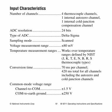
Input CharacteristicsNumber of channels.......................... 4 thermocouple channels,
1 internal autozero channel, 1 internal cold-junction compensation channel
ADC resolution................................. 24 bits
Type of ADC.....................................Delta-Sigma
Sampling mode ................................. Scanned
Voltage measurement range ..............±80 mV
Temperature measurement ranges ....Works over temperature ranges defined by NIST(J, K, T, E, N, B, R, S thermocouple types)
Conversion time................................ 70 ms per channel;420 ms total for all channels including the autozero and cold-junction channels
Common-mode voltage rangeChannel-to-COM........................ ±1.5 VCOM-to-earth ground................. ±250 V
NI 9211 Operating Instructions and Specifications 20 ni.com
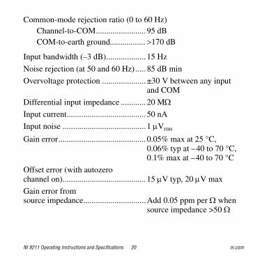
Common-mode rejection ratio (0 to 60 Hz)Channel-to-COM........................ 95 dBCOM-to-earth ground 170 dB
Input bandwidth (–3 dB)................... 15 Hz
Noise rejection (at 50 and 60 Hz) ..... 85 dB min
Overvoltage protection ..................... ±30 V between any inputand COM
Differential input impedance ............ 20 MInput current...................................... 50 nA
Input noise ........................................1 Vrms
Gain error.......................................... 0.05% max at 25 °C,0.06% typ at –40 to 70 °C,0.1% max at –40 to 70 °C
Offset error (with autozero channel on)........................................15 V typ, 20 V max
Gain error from source impedance..............................Add 0.05 ppm per when
source impedance >50
© National Instruments Corp. 21 NI 9211 Operating Instructions and Specifications
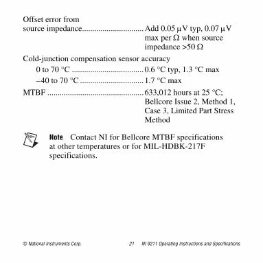
Offset error from source impedance..............................Add 0.05 V typ, 0.07 V
max per when source impedance >50
Cold-junction compensation sensor accuracy0 to 70 °C ................................... 0.6 °C typ, 1.3 °C max–40 to 70 °C ............................... 1.7 °C max
MTBF ...............................................633,012 hours at 25 °C; Bellcore Issue 2, Method 1, Case 3, Limited Part Stress Method
Note Contact NI for Bellcore MTBF specifications at other temperatures or for MIL-HDBK-217F specifications.
NI 9211 Operating Instructions and Specifications 22 ni.com
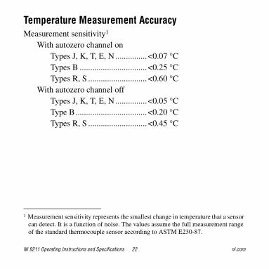
Temperature Measurement AccuracyMeasurement sensitivity1
With autozero channel onTypes J, K, T, E, N ............... <0.07 °CTypes B ................................ <0.25 °CTypes R, S ............................ <0.60 °C
With autozero channel offTypes J, K, T, E, N ............... <0.05 °CType B.................................. <0.20 °CTypes R, S ............................ <0.45 °C
1 Measurement sensitivity represents the smallest change in temperature that a sensor can detect. It is a function of noise. The values assume the full measurement range of the standard thermocouple sensor according to ASTM E230-87.
© National Instruments Corp. 23 NI 9211 Operating Instructions and Specifications
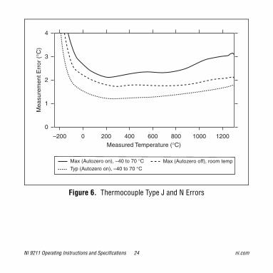
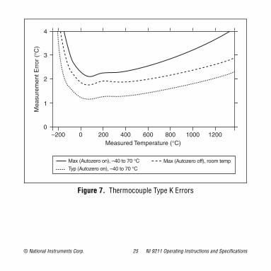
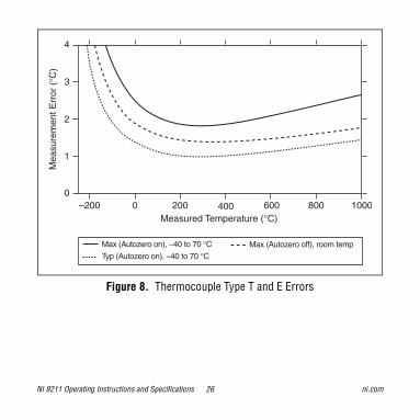
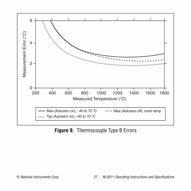
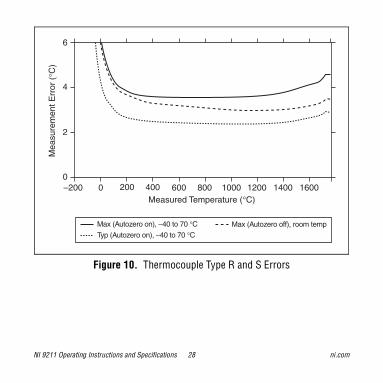
Figures 6, 7, 8, 9, and 10 show the typical and maximum errors for each thermocouple type when used with the NI 9211 over the full temperature range. The figures also display the maximum errors for the thermocouple types with the NI 9211 at room temperature, which is 15 to 35 °C. The figures account for gain errors, offset errors, differential and integral nonlinearity, quantization errors, noise errors, and isothermal errors. The figures do not account for the accuracy of the thermocouple itself.
NI 9211 Operating Instructions and Specifications 24 ni.com
Figure 6. Thermocouple Type J and N Errors
–200 0 200 400 600 800 1000 1200
0
1
2
3
4
Max (Autozero on), –40 to 70 °C Max (Autozero off), room temp
Typ (Autozero on), –40 to 70 °C
Mea
sure
men
t Err
or (
°C)
Measured Temperature (°C)
© National Instruments Corp. 25 NI 9211 Operating Instructions and Specifications
Figure 7. Thermocouple Type K Errors
–200 0 200 400 600 800 1000 12000
1
2
3
4M
easu
rem
ent E
rror
(°C
)
Measured Temperature (°C)
Max (Autozero on), –40 to 70 °C Max (Autozero off), room temp
Typ (Autozero on), –40 to 70 °C
NI 9211 Operating Instructions and Specifications 26 ni.com
Figure 8. Thermocouple Type T and E Errors
–200 0 200 400 600 800 10000
2
3
4M
easu
rem
ent E
rror
(°C
)
Measured Temperature (°C)
1
Max (Autozero on), –40 to 70 °C Max (Autozero off), room temp
Typ (Autozero on), –40 to 70 °C
© National Instruments Corp. 27 NI 9211 Operating Instructions and Specifications
Figure 9. Thermocouple Type B Errors
200 400 600 800 1200 1600 18000
2
4
6M
easu
rem
ent E
rror
(°C
)
1000 1400Measured Temperature (°C)
Max (Autozero on), –40 to 70 °C Max (Autozero off), room temp
Typ (Autozero on), –40 to 70 °C
NI 9211 Operating Instructions and Specifications 28 ni.com
Figure 10. Thermocouple Type R and S Errors
–200 0 200 400 600 800 1000 12000
2
4
6M
easu
rem
ent E
rror
(°C
)
1400 1600Measured Temperature (°C)
Max (Autozero on), –40 to 70 °C Max (Autozero off), room temp
Typ (Autozero on), –40 to 70 °C

© National Instruments Corp. 29 NI 9211 Operating Instructions and Specifications
Power RequirementsPower consumption from chassis
Active mode ............................... 170 mW maxSleep mode ................................. 4 mW max
Thermal dissipation (at 70 °C)Active mode ............................... 170 mW maxSleep mode ................................. 4 mW max
Physical CharacteristicsIf you need to clean the module, wipe it with a dry towel.
Note For two-dimensional drawings and three-dimensional models of the C Series module and connectors, visit ni.com/dimensions and search by module number.
Screw-terminal wiring ...................... 12 to 24 AWG copper conductor wire with 7 mm (0.28 in.) of insulation stripped from the end
Torque for screw terminals ............... 0.5 to 0.6 N · m (4.4 to 5.3 lb · in.)
NI 9211 Operating Instructions and Specifications 30 ni.com
Ferrules ............................................. 0.25 mm2 to 2.5 mm2
Weight ...............................................150 g (5.3 oz)
SafetySafety VoltagesConnect only voltages that are within the following limits.
Channel-to-COM 30 V max
IsolationChannel-to-channel ....................NoneChannel-to-earth ground
Continuous ........................... 250 Vrms, Measurement Category II
Withstand .............................2,300 Vrms, verified by a 5 s dielectric withstand test
Measurement Category II is for measurements performed on circuits directly connected to the electrical distribution system. This category refers to local-level electrical distribution, such as that provided by a standard wall outlet, for example, 115 V for U.S. or 230 V for Europe.
© National Instruments Corp. 31 NI 9211 Operating Instructions and Specifications
Caution Do not connect the NI 9211 to signals or use for measurements within Measurement Categories III or IV.
Hazardous LocationsU.S. (UL) ..........................................Class I, Division 2,
Groups A, B, C, D, T4;Class I, Zone 2,AEx nC IIC T4
Canada (C-UL) .................................Class I, Division 2, Groups A, B, C, D, T4;Class I, Zone 2, Ex nC IIC T4
Europe (DEMKO).............................Ex nC IIC T4
Safety StandardsThis product meets the requirements of the following standards of safety for electrical equipment for measurement, control, and laboratory use:
• IEC 61010-1, EN 61010-1
• UL 61010-1, CSA 61010-1
NI 9211 Operating Instructions and Specifications 32 ni.com
Note For UL and other safety certifications, refer to the product label or the Online Product Certification section.
Electromagnetic CompatibilityThis product meets the requirements of the following EMC standards for electrical equipment for measurement, control, and laboratory use:
• EN 61326-2-1 (IEC 61326-2-1): Class A emissions; Industrial immunity
• EN 55011 (CISPR 11): Group 1, Class A emissions
• AS/NZS CISPR 11: Group 1, Class A emissions
• FCC 47 CFR Part 15B: Class A emissions
• ICES-001: Class A emissions
Caution For EMC compliance, operate this device with shielded cables.
Note For the standards applied to assess the EMC of this product, refer to the Online Product Certification section.
© National Instruments Corp. 33 NI 9211 Operating Instructions and Specifications
CE ComplianceThis product meets the essential requirements of applicable European directives as follows:
• 2006/95/EC; Low-Voltage Directive (safety)
• 2004/108/EC; Electromagnetic Compatibility Directive (EMC)
Online Product CertificationTo obtain product certifications and the Declaration of Conformity (DoC) for this product, visit ni.com/certification, search by module number or product line, and click the appropriate link in the Certification column.
NI 9211 Operating Instructions and Specifications 34 ni.com
Shock and VibrationTo meet these specifications, you must panel mount the system and either affix ferrules to the ends of the terminal wires or use the NI 9932 backshell kit to protect the connections.
Operating vibrationRandom (IEC 60068-2-64)......... 5 grms, 10 to 500 Hz
Sinusoidal (IEC 60068-2-6) .......5 g, 10 to 500 Hz
Operating shock(IEC 60068-2-27).............................. 30 g, 11 ms half sine,
50 g, 3 ms half sine,18 shocks at 6 orientations
EnvironmentalNational Instruments C Series modules are intended for indoor use only but may be used outdoors if installed in a suitable enclosure. Refer to the manual for the chassis you are using for more information about meeting these specifications.
Operating temperature(IEC 60068-2-1, IEC 60068-2-2) ..... –40 to 70 °C
Storage temperature(IEC 60068-2-1, IEC 60068-2-2) ..... –40 to 85 °C

© National Instruments Corp. 35 NI 9211 Operating Instructions and Specifications
Ingress protection.............................. IP 40
Operating humidity(IEC 60068-2-56).............................. 10 to 90% RH,
noncondensing
Storage humidity(IEC 60068-2-56).............................. 5 to 95% RH,
noncondensing
Maximum altitude.............................2,000 m
Pollution Degree ............................... 2
Environmental ManagementNI is committed to designing and manufacturing products in an environmentally responsible manner. NI recognizes that eliminating certain hazardous substances from our products is beneficial to the environment and to NI customers.
For additional environmental information, refer to the NI and the Environment Web page at ni.com/environment. This page contains the environmental regulations and directives with which NI complies, as well as other environmental information not included in this document.
NI 9211 Operating Instructions and Specifications 36 ni.com
Waste Electrical and Electronic Equipment (WEEE)EU Customers At the end of the product life cycle, all products must be sent to a WEEE recycling center. For more information about WEEE recycling centers, National Instruments WEEE initiatives, and compliance with WEEE Directive 2002/96/EC on Waste and Electronic Equipment, visit ni.com/environment/weee.
CalibrationYou can obtain the calibration certificate and information about calibration services for the NI 9211 at ni.com/calibration.
Calibration interval ........................... 1 year
RoHSNational Instruments
(RoHS)National Instruments RoHSni.com/environment/rohs_china (For information about China RoHS compliance, go to ni.com/environment/rohs_china.)

© National Instruments Corp. 37 NI 9211 Operating Instructions and Specifications
Where to Go for SupportThe National Instruments Web site is your complete resource for technical support. At ni.com/support you have access to everything from troubleshooting and application development self-help resources to email and phone assistance from NI Application Engineers.
National Instruments corporate headquarters is located at 11500 North Mopac Expressway, Austin, Texas, 78759-3504. National Instruments also has offices located around the world to help address your support needs. For telephone support in the United States, create your service request at ni.com/support and follow the calling instructions or dial 512 795 8248. For telephone support outside the United States, contact your local branch office:
Australia 1800 300 800, Austria 43 662 457990-0, Belgium 32 (0) 2 757 0020, Brazil 55 11 3262 3599, Canada 800 433 3488, China 86 21 5050 9800, Czech Republic 420 224 235 774, Denmark 45 45 76 26 00, Finland 358 (0) 9 725 72511, France 01 57 66 24 24, Germany 49 89 7413130, India 91 80 41190000, Israel 972 3 6393737, Italy 39 02 41309277, Japan 0120-527196,
NI 9211 Operating Instructions and Specifications 38 ni.com
Korea 82 02 3451 3400, Lebanon 961 (0) 1 33 28 28, Malaysia 1800 887710, Mexico 01 800 010 0793, Netherlands 31 (0) 348 433 466, New Zealand 0800 553 322, Norway 47 (0) 66 90 76 60, Poland 48 22 328 90 10, Portugal 351 210 311 210, Russia 7 495 783 6851, Singapore 1800 226 5886, Slovenia 386 3 425 42 00, South Africa 27 0 11 805 8197, Spain 34 91 640 0085, Sweden 46 (0) 8 587 895 00, Switzerland 41 56 2005151, Taiwan 886 02 2377 2222, Thailand 662 278 6777, Turkey 90 212 279 3031, United Kingdom 44 (0) 1635 523545
© 2003–2010 National Instruments Corp. All rights reserved.
373466E-01 Oct10
LabVIEW, National Instruments, NI, ni.com, the National Instruments corporate logo, and the Eagle logo are trademarks of National Instruments Corporation. Refer to the Trademark Information at ni.com/trademarks for other National Instruments trademarks. Other product and company names mentioned herein are trademarks or trade names of their respective companies. For patents covering National Instruments products/technology, refer to the appropriate location: Help»Patents in your software, the patents.txt file on your media, or the National Instruments Patent Notice at ni.com/patents.