nGenuity 8100E Series Vital Signs Monitor Operator’s … 8… · · 2018-03-098100E Series...
182
nGenuity TM 8100E Series Vital Signs Monitor Operator’s Manual Cat. No. 1447 Date 01/10 Part No. 39179B001 Revision 3
Transcript of nGenuity 8100E Series Vital Signs Monitor Operator’s … 8… · · 2018-03-098100E Series...
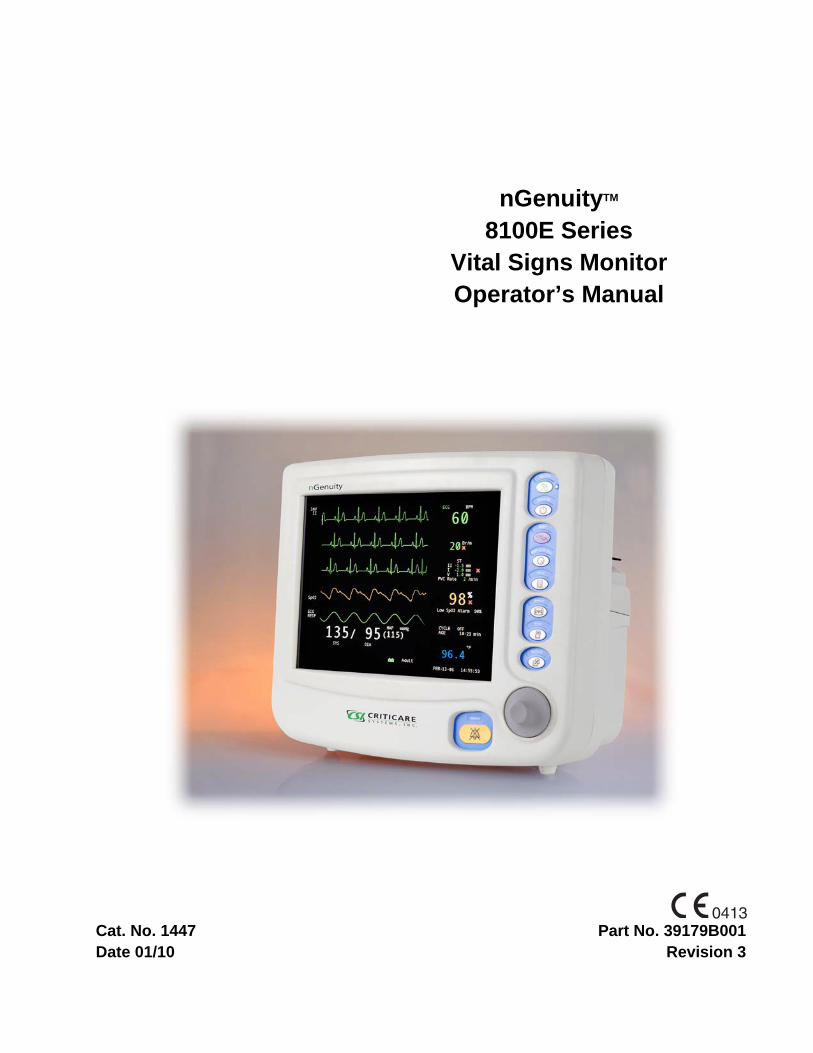
nGenuityTM
8100E SeriesVital Signs Monitor Operator’s Manual
Cat. No. 1447Date 01/10
Part No. 39179B001Revision 3

Page ii nGenuityTM 8100E Series Operator’s Manual Criticare Systems, Inc.
Copyright
COPYRIGHT © CRITICARE SYSTEMS, INC., 2006-2010
CRITICARE SYSTEMS, INC. (Criticare) owns all rights to this unpublished work and intends to maintain this work as confidential. Criticare may also seek to maintain this work as an unpublished copyright. This publication is to be used solely for the purposes of reference, operation, maintenance, or repair of Criticare equipment. No part of this publication may be reproduced in any manner or disseminated for other purposes.
In the event of inadvertent or deliberate publication, Criticare intends to enforce its rights to this work under copyright laws as a published work. Those having access to this work may not copy, use, or disclose the information in this work unless expressly authorized by Criticare to do so.
All product specifications, as well as information contained in this publication, are subject to change without notice.
All information contained in this publication is believed to be correct. Criticare Systems, Inc., shall not be liable for errors contained herein nor for incidental or consequential damages in connection with the furnishing, performance, or use of this material.
This publication may refer to information and products protected by copyrights or patents and does not convey any license under the patent rights of Criticare Systems, Inc., nor the rights of others. Criticare Systems, Inc., does not assume any liability arising out of any infringements of patents or other rights of third parties.
PROPERTY OF CRITICARE SYSTEMS, INC.ALL RIGHTS RESERVED
nGenuity™ Vital Signs Monitor, DOX™ Digital Oximetry, ComfortCuff™ NIBP and Multi-Site™ SpO2 Sensors are trademarks of Criticare Systems, Inc.

Criticare Systems, Inc. nGenuityTM 8100E Series Operator’s Manual Page iii
ContentsCopyright................................................................................................................ iiContents................................................................................................................ iiiWarranty................................................................................................................xiService Return Policy........................................................................................... xiiEC Declaration of Conformity.............................................................................. xiii
Section 1 - Introduction
Description .................................................................................................................... 1-1Intended Use................................................................................................................. 1-1nGenuity 8100E Series Options.................................................................................... 1-1Pulse Oximetry Measurement (SpO2) .......................................................................... 1-2
Definition ............................................................................................................ 1-2DOX™ Digital Oximetry ..................................................................................... 1-2Method ............................................................................................................... 1-2SpO2 Clinical Testing and Accuracy .................................................................. 1-3
Heart Rate..................................................................................................................... 1-4ECG Measurement ....................................................................................................... 1-4
Method ............................................................................................................... 1-4Stability of Accuracy........................................................................................... 1-5Pacemaker Pulse Rejection ............................................................................... 1-5
Respiration.................................................................................................................... 1-5Non-Invasive Blood Pressure (NIBP)............................................................................ 1-6
Comfort Cuff™ Technology................................................................................ 1-6Description of NIBP Measurement..................................................................... 1-6NIBP Clinical Testing and Accuracy................................................................... 1-7Cuff Inflation and Pressure Protection ............................................................... 1-7
Capnography ................................................................................................................ 1-8Method of Measurement .................................................................................... 1-8Conditions of Use............................................................................................... 1-9Stability of Accuracy........................................................................................... 1-9N2O Compensation ............................................................................................ 1-9
Temperature Measurement .......................................................................................... 1-9Specifications.............................................................................................................. 1-10Symbols ...................................................................................................................... 1-14Safety.......................................................................................................................... 1-16
Definitions ........................................................................................................ 1-16Warnings .......................................................................................................... 1-16Cautions ........................................................................................................... 1-17Leakage Current .............................................................................................. 1-18Voltage Fluctuations......................................................................................... 1-18Equipotential Ground ....................................................................................... 1-18Software Error Related Hazard Mediation ....................................................... 1-18Potential Interference....................................................................................... 1-19Biocompatibility ................................................................................................ 1-19Latex Content................................................................................................... 1-19DEHP Content.................................................................................................. 1-19

Page iv nGenuityTM 8100E Series Operator’s Manual Criticare Systems, Inc.
Contents
Section 2 - Controls and Connections
Front Panel....................................................................................................................2-1Keypad ...............................................................................................................2-2AC Power Indicator.............................................................................................2-3Rotary Menu Knob..............................................................................................2-3Color Display ......................................................................................................2-3
Left Side Panel ..............................................................................................................2-4Water Trap and Sampling Connection ...............................................................2-5
Rear Panel and Fixtures................................................................................................2-6Communication Sockets.....................................................................................2-7Service Access Panel.........................................................................................2-7Chassis Ground..................................................................................................2-8AC Power Cable Connection..............................................................................2-8Fuse Access Panel.............................................................................................2-8Optional Printer...................................................................................................2-8
Screen Display and Interface ........................................................................................2-9Waveform Slots ................................................................................................2-11Numerical Parameter Boxes.............................................................................2-13Main Menu........................................................................................................2-15Alarm and Message Areas ...............................................................................2-15System Status Box ...........................................................................................2-15Patient Information and Clock ..........................................................................2-16
Section 3 - Setup Procedure
Monitor Setup ................................................................................................................3-1Battery Power................................................................................................................3-1
Charging the Monitor ..........................................................................................3-1Battery Indicators................................................................................................3-2
System Start and Auto-calibration.................................................................................3-3Sensor and Probe Messages .............................................................................3-3CO2 Calibration ..................................................................................................3-4
Softkey Functions (Main Menu).....................................................................................3-5Changing Settings ..............................................................................................3-5Saved Setting Profiles ........................................................................................3-6
ALARMS Softkey...........................................................................................................3-7Alarms Settings by Patient Size .........................................................................3-8Alarm Limits........................................................................................................3-8ECG Lead Fail ....................................................................................................3-8Alarm Volume.....................................................................................................3-9Low SpO2 Alarm.................................................................................................3-9
PARAMS Softkey (Physiological Parameters) ............................................................3-10HR Source (Smart Heart Rate).........................................................................3-10ECG Settings....................................................................................................3-10Filter Settings....................................................................................................3-11Monitoring Module On/Off Selection.................................................................3-11SpO2 Settings...................................................................................................3-11Respiration Smart Source ................................................................................3-12NIBP Settings ...................................................................................................3-12Temperature Settings .......................................................................................3-12Heart Rate Tone Volume (Pulse Tone) ............................................................3-12Color Settings ...................................................................................................3-12CO2 Settings.....................................................................................................3-12
DISPLAY Softkey ........................................................................................................3-13Waveform Description ......................................................................................3-13Double Height Slots..........................................................................................3-14Cascaded Slots ................................................................................................3-15Gain and Sweep...............................................................................................3-16

Criticare Systems, Inc. nGenuityTM 8100E Series Operator’s Manual Page v
Contents
Mini-Trends ................................................................................................................. 3-16Setting Mini-Trend............................................................................................ 3-16Initiating Mini-Trend.......................................................................................... 3-17Mini-Trend Display ........................................................................................... 3-17
ADM/DIS Softkey (Admit/Discharge) .......................................................................... 3-19Adult/Pediatric/Neonatal (Patient Size) ............................................................ 3-19Admitting and Discharging Patients ................................................................. 3-20Patient Information ........................................................................................... 3-20Procedure for Admitting a Patient .................................................................... 3-21Procedure for Discharging a Patient ................................................................ 3-21
CONFIG Softkey (System Configuration) ................................................................... 3-22Password Protection ........................................................................................ 3-22Time/Date Setting ............................................................................................ 3-23Freeze Waveforms........................................................................................... 3-23Alarm Tone Warning ........................................................................................ 3-23Language Settings ........................................................................................... 3-23
Printer Settings ........................................................................................................... 3-25Printer Type...................................................................................................... 3-25Serial Type....................................................................................................... 3-25
Default Settings........................................................................................................... 3-26Alarms Settings ................................................................................................ 3-26Monitoring Parameters..................................................................................... 3-27Display Settings ............................................................................................... 3-28Configuration Settings...................................................................................... 3-29Printer Settings................................................................................................. 3-29
Section 4 - Patient Monitoring
Introduction to Clinical Use ........................................................................................... 4-1Before you Begin................................................................................................ 4-1
SpO2 Monitoring (Pulse Oximetry)................................................................................ 4-2Sensor Selection ................................................................................................ 4-4SpO2 Sensor Placement .................................................................................... 4-5Multi-Site™ Sensor Placement .......................................................................... 4-6Using SpO2 Sensors .......................................................................................... 4-7
ECG Monitoring (Electrocardiogram)............................................................................ 4-8Pacemakers and Electronic Devices.................................................................. 4-9Tall T-Wave Performance .................................................................................. 4-9Narrow Beat Rejection ....................................................................................... 4-9Electrode Selection ............................................................................................ 4-9Lead Placement ............................................................................................... 4-103-Lead Setup.................................................................................................... 4-105-Lead Setup.................................................................................................... 4-11Electrode Application ....................................................................................... 4-12
ECG Auto Lead Switching .......................................................................................... 4-13Primary Lead.................................................................................................... 4-13Alternate Lead Priority...................................................................................... 4-14
NIBP Monitoring (Non-invasive Blood Pressure) ........................................................ 4-15Selecting Cuffs and Hoses............................................................................... 4-16Placing the NIBP Cuff ...................................................................................... 4-17Procedure......................................................................................................... 4-17Taking NIBP Measurements ............................................................................ 4-18
Gas Monitoring............................................................................................................ 4-19Sampling Cicuit Connections ........................................................................... 4-19Water Trap ....................................................................................................... 4-21Sampling Devices ............................................................................................ 4-21Intubated Patients ............................................................................................ 4-22Calibration and Startup .................................................................................... 4-23Procedure for Gas Monitoring .......................................................................... 4-24Occlusions........................................................................................................ 4-24Anesthetic Gas Exhaust Recovery................................................................... 4-24CO2 Monitoring ................................................................................................ 4-25
Page vi nGenuityTM 8100E Series Operator’s Manual Criticare Systems, Inc.
Contents
Temperature Monitoring ..............................................................................................4-26Using Temperature Accessories ......................................................................4-27Directions for Use with Skin Surface Probe......................................................4-28Directions for Use with Esophageal/Rectal Probe............................................4-28Cleaning ...........................................................................................................4-28
Section 5 - Alarms and Messages
Alarm Description ..........................................................................................................5-1Audible Alarms ...................................................................................................5-1Visible Alarms.....................................................................................................5-2Waveforms Frozen .............................................................................................5-2Alert Icons...........................................................................................................5-3
Special Alarm Conditions ..............................................................................................5-3Alarms at Start Up ..............................................................................................5-3Alarm Silence .....................................................................................................5-3Audible Alarms Disabled (Warning Tone) ..........................................................5-4Alarm Volume.....................................................................................................5-4Minimum Volume Auto-Reset.............................................................................5-4Standby Mode ....................................................................................................5-4SpO2 Low Limit Auto-Reset................................................................................5-5SpO2 Low Limit Off Alarm ..................................................................................5-5
Alarms Testing ..............................................................................................................5-5Alarm Message List.......................................................................................................5-6
Shared Source Alarms .......................................................................................5-6ECG Alarms........................................................................................................5-6Respiration Alarms .............................................................................................5-6SpO2 Alarms.......................................................................................................5-7Temperature Alarms...........................................................................................5-7NIBP Alarms.......................................................................................................5-8Gas Alarms.........................................................................................................5-9System Alerts ...................................................................................................5-10
Section 6 - Trends
Description ....................................................................................................................6-1Trend Interval .....................................................................................................6-1Capacity..............................................................................................................6-1Trend Screen Update .........................................................................................6-1
Trend Setup...................................................................................................................6-2Graphical Trends...........................................................................................................6-4
Scrolling the Graph.............................................................................................6-4Interruption Due to Power Cycling......................................................................6-4Graphical Trend Screen .....................................................................................6-5
Tabular Trends ..............................................................................................................6-6Heart Rate Source Indication .............................................................................6-6Respiration Source Indication.............................................................................6-6Tabular Trend Markers .......................................................................................6-6Trend Messages.................................................................................................6-6Data Format........................................................................................................6-7NIBP View ..........................................................................................................6-8
Clearing the Memory .....................................................................................................6-8

Criticare Systems, Inc. nGenuityTM 8100E Series Operator’s Manual Page vii
Contents
Section 7 - Printing and Data Ports
Description .................................................................................................................... 7-1Snapshot Size .................................................................................................... 7-1History Size ........................................................................................................ 7-1
Print Modes................................................................................................................... 7-1Demand Print ..................................................................................................... 7-1Continuous Print................................................................................................. 7-1Alarm Print ......................................................................................................... 7-1BP Print .............................................................................................................. 7-2Interval Print ....................................................................................................... 7-2Freeze Print........................................................................................................ 7-2Trend Print ......................................................................................................... 7-2
Print Formats ................................................................................................................ 7-3Tabular Printing.................................................................................................. 7-3Graphical Printing............................................................................................... 7-4Mini-Trend Printing............................................................................................. 7-5
Changing Printer Paper ................................................................................................ 7-6Data Output Ports ......................................................................................................... 7-7
COM1 Port ......................................................................................................... 7-7COM2 Port ......................................................................................................... 7-9
Defibrillation Connector............................................................................................... 7-10Nurse Call ................................................................................................................... 7-10Video Port ................................................................................................................... 7-10CSV Data Format........................................................................................................ 7-11
Section 8 - Maintenance
Cleaning, Disinfecting, and Testing .............................................................................. 8-1Pulse Oximeter Sensors .................................................................................... 8-1Blood Pressure Cuffs ......................................................................................... 8-2Temperature Cable ............................................................................................ 8-3Temperature Sensors ........................................................................................ 8-3
Accidental Wetting ........................................................................................................ 8-4Serviceable Components.............................................................................................. 8-5
Changing the Battery ......................................................................................... 8-5Changing the Fuses ........................................................................................... 8-5
Annual Safety Tests...................................................................................................... 8-7System Testing .................................................................................................. 8-7Accessory Testing.............................................................................................. 8-7Service Checks .................................................................................................. 8-7Printer Check ..................................................................................................... 8-7Alarms Verification ............................................................................................. 8-8
Maintenance Schedule ................................................................................................. 8-9Every Patient...................................................................................................... 8-9Every Day........................................................................................................... 8-9Every Week........................................................................................................ 8-9Every 3 Months .................................................................................................. 8-9Every Year ......................................................................................................... 8-9
Battery Maintenance..................................................................................................... 8-9Long-Term Storage....................................................................................................... 8-9Disposal ........................................................................................................................ 8-9

Page viii nGenuityTM 8100E Series Operator’s Manual Criticare Systems, Inc.
Contents
Appendix A — Accessories
SpO2 Accessories ........................................................................................................ A-1Reusable Sensors ............................................................................................. A-1Multi-site Sensor Accessories ........................................................................... A-1Disposable Sensors........................................................................................... A-1
ECG Accessories ......................................................................................................... A-2Universal ECG Cables....................................................................................... A-2
NIBP Accessories......................................................................................................... A-3Cuffs and Hoses................................................................................................ A-3Disposable Cuffs ............................................................................................... A-3
Temperature Probes .................................................................................................... A-4Reusable Probes............................................................................................... A-4Disposable Probes ............................................................................................ A-4
Gas Monitoring Accessories......................................................................................... A-4Sampling Devices.............................................................................................. A-4Calibration Accessories ..................................................................................... A-5Calibration Kits .................................................................................................. A-5
Other Accessories Available ........................................................................................ A-5Publications .................................................................................................................. A-6
Appendix B — Alternate Care Defaults
Alternate Care Defaults ................................................................................................ B-1Configuration Settings for Alternate Care Facilities...................................................... B-3
PARAMS Menu Settings ................................................................................... B-3PRINT Menu Settings........................................................................................ B-3DISPLAY Menu Settings ................................................................................... B-4ALARMS Menu Settings.................................................................................... B-4Other Alarm Settings ......................................................................................... B-4

Criticare Systems, Inc. nGenuityTM 8100E Series Operator’s Manual Page ix
Contents
Appendix C — Arrhythmia and ST Analysis
Arrhythmia and ST Analysis Software ..........................................................................C-1Description ....................................................................................................................C-1
Intended Use......................................................................................................C-1Compatibility.......................................................................................................C-1
Software Agreement .....................................................................................................C-2Activation............................................................................................................C-2
Compliance ...................................................................................................................C-3Transient Power .................................................................................................C-3Lead Off Detection .............................................................................................C-3Respiration .........................................................................................................C-3Sudden Changes In Heart Rate .........................................................................C-3
Method of Analysis........................................................................................................C-4Cautions and Warnings......................................................................................C-5
Specifications................................................................................................................C-6Interface Screens..........................................................................................................C-7
Setup Windows ..................................................................................................C-8ST/Arrhythmia Defaults...............................................................................................C-11
Alarms Settings, Arrhythmia Setup ..................................................................C-11Alarms Settings, ST Setup ...............................................................................C-12ST / Arrhythmia Monitoring Parameters...........................................................C-13Display Settings ...............................................................................................C-13
ST Trends ...................................................................................................................C-14Graphical Trend Screen ...................................................................................C-14Tabular Trend Markers and Messages ............................................................C-15Data Format with ST ........................................................................................C-15
Clinical Preparation.....................................................................................................C-15Accessories......................................................................................................C-15
Clinical Use .................................................................................................................C-16Pacemaker Detection.......................................................................................C-16Defibrillation .....................................................................................................C-16
Arrhythmia Detection ..................................................................................................C-16ST Segment Analysis..................................................................................................C-16
Description .......................................................................................................C-16Starting ST .......................................................................................................C-17ST Filter............................................................................................................C-17Learn ................................................................................................................C-17ST, J, and ISO Points.......................................................................................C-17Automatic ST Segment Detection ....................................................................C-18ST, J, and ISO Point Manual Adjustment.........................................................C-19
Tabular Printing...........................................................................................................C-20ST and Arrhythmia Alarm Description.........................................................................C-21
Alarm Conditions..............................................................................................C-21Arrhythmia Alerts..............................................................................................C-22ST Alerts ..........................................................................................................C-23

Criticare Systems, Inc. nGenuityTM 8100E Series Operator’s Manual Page xi
Warranty
Workmanship & Materials
Criticare Systems, Inc. (CSI) warranties new equipment to be free from defects in workmanship and materials for a period of one (1) year from date of shipment under normal use and service. The 940 Series Multi-SiteTM Sensor carries a six month warranty. CSI’s obligation under this warranty is limited to repairing or replacing, at CSI’s option, any part which upon CSI’s examination proves defective.
EXCEPT AS DESCRIBED IN THE PARAGRAPH ABOVE, CSI MAKES NO WARRANTIES, EXPRESS OR IMPLIED, INCLUDING ANY WARRANTY OF MERCHANTABILITY OR FITNESS FOR A PARTICULAR PURPOSE.
Exemptions CSI’s obligation or liability under this warranty does not include any transportation or other charges or liability for direct, indirect or consequential damages or delay resulting from the improper use or application of the product or the substitution upon it of parts or accessories not approved by CSI or repair by anyone other than a CSI authorized representative.
This warranty shall not extend to any instrument which has been subjected to misuse, negligence or accident; any instrument from which CSI’s original serial number tag or product identification markings have been altered or removed; or any product of any other manufacturer.
Safety, Reliability & Performance
Criticare Systems, Inc., is not responsible for the effects on safety, reliability and performance of the 8100E Series Patient Monitor if: assembly operations, extensions, readjustments, modifications or repairs are carried out by persons other than those authorized by Criticare Systems, Inc., or
the 8100E Series Patient Monitor is not used in accordance with the instructions for use, or
the electrical installation of the relevant room does not comply with NFPA 70: National Electric Code or NFPA 99: Standard for Health Care Facilities (Outside the United States, the relevant room must comply with all electrical installation regulations mandated by the local and regional bodies of government).
In Case of Emergency Contact
CRITICARE SYSTEMS, INC. Telephone: (262) 798-828220925 Crossroads Circle Tech Support: (800) 458-2697Waukesha, WI 53186 Orders: (800) 458-4615USA Fax: (262) 798-8290
Internet: www.csiusa.com

Page xii nGenuityTM 8100E Series Operator’s Manual Criticare Systems, Inc.
Service Return Policy
Return Procedure In the event that it becomes necessary to return a unit to Criticare Systems, Inc., the following procedure should be followed:Obtain return authorization. Contact the CSI Service Department at 800-458-2697 to obtain a Customer Service Authorization (CSA) number. (Outside the US, call 001-262-798-8282.) The CSA number must appear on the outside of the shipping container. Return shipments will not be accepted if the CSA number is not clearly visible. Please provide the model number, serial number, and a brief description of the reason for return.
Freight policy. The customer is responsible for freight charges when equipment is shipped to CSI for service (this includes customs charges).
Loaner service. In the U.S. If it is necessary to provide a loaner system, CSI will ship a loaner by overnight courier. The loaner system must be returned to CSI at the customer’s expense within one week after receipt of the repaired goods. If the unit is not returned to CSI within that time, the customer will be invoiced for the full purchase price of the equipment.
Outside the U.S. No loaners are available from CSI internationally. Contact your local CSI representative.
Incoming Inspection The following incoming inspection is required whether it is a first time arrival or a return from service. Prior to clinical use, the instrument should be inspected for the following.
1. The quality inspection seal on the instrument should be unbroken. This seal indicates that the instrument has been tested according to manufacturers specifications.
2. No physical damage is observed.
3. The instrument's battery is to be charged by connecting the instrument to a power outlet for a minimum of 4.5 hours prior to clinical use.
4. When connecting the instrument to a power outlet and then turning the instrument on, all displays appear to function correctly and no system errors occur.
If a discrepancy to these inspection items is observed, do not use the instrument and immediately report the discrepancy to the CSI Service Department.

Criticare Systems, Inc. nGenuityTM 8100E Series Operator’s Manual Page xiii
EC Declaration of Conformity
Model 8100E Series Patient Monitor
To view the Declaration of Conformity, visit the Criticare website at www.csiusa.com. A copy of the Declaration can also be faxed. Contact Criticare’s customer service department at (262) 798-8282 to obtain a faxed copy of the Declaration.
Representative in the European Union
MDSS GmbHSchiffgraben 4130175 HannoverGermany


Criticare Systems, Inc. nGenuityTM 8100E Series Operator’s Manual Page 1-1
Section 1 — Introduction
Description The nGenuity 8100E Series monitor interprets and displays real time physiological data including waveforms and numerical data. The monitor is designed for multi-parameter measurements, including ECG, NIBP, SpO2, temperature, and respiration. Optional CO2 monitoring is also available. For all these vital parameters, the 8100E Series monitor has limit alarms and alerts. The monitor also prints strip chart recordings and stores tabular trends for review.
Intended Use The 8100E Series monitor is intended to monitor physiological parameters of patients within clinical care settings. It is intended that the user is a professional health care provider. Physiological data, system alarms, and patient data analysis are available to the care provider from the monitor.
The user is responsible for the interpretation of the monitored data that is made available. Physiological data should be reviewed by a qualified clinical personnel prior to any medical intervention.
The monitor is designed to be used with only one patient at a time. The monitor (including accessories) is capable of monitoring a full range of patients from neonate to adult.
nGenuity 8100E Series Options
The nGenuity 8100E Series monitor comes standard with 5-Lead ECG, ComfortCuff™ NIBP, DOX™ SpO2, and one temperature channel for monitoring. Options include internal printer and CO2 monitoring. A color TFT screen with a six waveform display is standard on all nGenuity 8100E Series models.
The nGenuity 8100E Series monitor is also available with ST and Arrhythmia analysis as an option.
Catalog Number Printer Additional Features
8100E No Standard
8100E-ST No ST Arrhythmia
8100E1 No CO2
8100E1-ST No CO2, ST Arrhythmia
8100EP Yes Standard
8100EP-ST Yes ST Arrhythmia
8100EP1 Yes CO2
8100EP1-ST Yes CO2, ST Arrhythmia

Section 1 —Introduction
Page 1-2 nGenuityTM 8100E Series Operator’s Manual Criticare Systems, Inc.
Pulse Oximetry Measurement (SpO2)
The monitor uses Digital Oximetry (DOX) technology to measure blood oxygen saturation (SpO2).
Definition Hemoglobin exists in the blood in several forms:
• Oxygenated (Oxyhemoglobin)
• Reduced (Deoxyhemoglobin)
• Dyshemoglobins (carboxyhemoglobin and methemoglobin.)
In the monitor, SpO2 (pulse arterial oxygen saturation) is the ratio of oxygenated hemoglobin to the sum of oxygenated hemoglobin plus hemoglobin which is available for binding to oxygen, as expressed in the following formula:
Dyshemoglobins, such as carboxyhemoglobin and methemoglobin, are not directly measured and therefore are not factored into the measurement.
DOX™ Digital Oximetry The monitor does not use analog circuitry for signal processing. Digital signal processing in the microprocessor results in lower noise from circuitry components, resulting in a cleaner signal and better performance under low perfusion conditions. There is also improved rejection of noise from the patient and environment, due to the availability of the “true,” unfiltered sensor signal for digital signal processing.
Method The digital pulse oximeter measures oxygen saturation and pulse rate using the principles of spectrophotometry and plethysmography. The sensor is completely non-invasive, and there is no heat source that could burn the patient.
The pulse oximeter sensor contains two types of LEDs. Each type emits a specific wavelength of light. Since oxygenated hemoglobin and deoxygenated hemoglobin absorb light selectively and predictably, the amounts of these two compounds can be determined by measuring the intensity of each wavelength that passes through the measuring site.
percent oxygen sa tura tionoxyhemoglobin
oxyhemoglobin deoxyhemoglobin+------------------------------------------------------------------------------------------------ 100×=

Criticare Systems, Inc. nGenuityTM 8100E Series Operator’s Manual Page 1-3
Section 1 —Introduction
The light from the LEDs shines into a pulsating vascular bed. A photodetector located opposite or alongside the LEDs measures the intensity of each wavelength transmitted through the monitoring site. The light intensity is converted to an electrical signal, which is input to the monitor. The effects of skin pigmentation, venous blood, and other tissue constituents are eliminated by separating out the pulsating absorption data.
SpO2 is calculated with every pulse and averaged with the results from previous pulses to arrive at the current numeric display value. The display is updated at least once per second with the numeric values that were calculated during the intervening period.
The plethysmographic pulse wave is not auto-gained. The amplitude display of the plethysmographic pulse wave is proportional to the pulse volume changes occurring in the tissue illuminated by the SpO2 sensor.
SpO2 Clinical Testingand Accuracy
All Criticare oximeters (DOX™ compatible) have SpO2 calibration tables which were originally generated by monitoring desaturated human patients or volunteers and matching their displayed SpO2 value to the value determined by sampling arterial blood and measuring functional SaO2 with a clinical laboratory grade multi wavelength optical oximeter (i.e. CO-oximeter). The final SpO2 calibration curve was then generated based upon numerous patients' data over the range of 40 to 99% SaO2. All accepted data were taken from patients with dyshemoglobin (i.e., carboxyhemoglobin, methemoglobin) concentrations near zero.
This oximeter is a two-wavelength device, which is calibrated to measure functional SpO2 only when dyshemoglobin concentrations are near zero. The accuracy specifications of this device will not be met with high concentrations of dyshemoglobins. Significant concentrations of carboxyhemoglobin results in a higher displayed SpO2 value than is actually present in the patient.
SpO2 clinical accuracy validation to CO-oximeter SaO2 readings was performed for this sensor using a DOX-compatible monitor.
The personal demographics of the study participants for the SpO2 clinical accuracy validation include a mix of adult males and females from 18 - 45 years of age. All were healthy during the course of the study. Physical characteristics and skin tone were by chance with a mix from slight to stout and light to dark.

Section 1 —Introduction
Page 1-4 nGenuityTM 8100E Series Operator’s Manual Criticare Systems, Inc.
Heart Rate The heart rate is determined primarily from the ECG waveform data. A beat detection algorithm is used to identify QRS beats.
The monitor has a user selectable smart heart rate function. It automatically uses alternate sources to determine heart rate, if the primary source becomes unmeasurable. The plethysmograph (SpO2 waveform) is used if the ECG heart rate is unavailable. In the absence of SpO2 and ECG data, the NIBP oscillometric data is the final default source for a heart rate measurement.
Response times for the ECG heart rate meter change from 80 BPM to 40 BPM and from 80 BPM to 120 BPM is less than or equal to 10 seconds. The alarm for tachycardia is less than or equal to 10 seconds per EC-13.
The pulse rate accuracy for SpO2 is the root-mean-square (rms) difference between paired pulse rate data recorded with the pulse oximeter and a reference method.
NOTE: The accuracy of the heart rate depends upon the source. The range of the measurable NIBP based heart rate does not extend as far as the range available in other modules used by the smart heart rate feature.
NOTE: The NIBP based heart rate is not a continuous measurement and is only current during an NIBP measurement.
ECG Measurement The electrocardiogram (ECG or EKG) records the changing potential generated by electrical activity of the heart.
Method To obtain an overall view of the heart's electrical activity, three or five electrodes attached to lead wires detect electrical impulses from the patient's heart to the skin. The monitor calculates the difference in electrical force between two electrode sites. Electrode polarity (positive, negative, or ground) depends on the cable receptacle the lead wire is attached to and the lead selected on the monitor screen.
The ECG design uses the standard (conventional bipolar limb leads) leads I, II, III using 3-lead or 5-lead cable accessory. With the 5-Lead cable accessory, leads aVR, aVL, aVF, and V lead may also be viewed.
The monitor has user selectable automatic lead switching capability when using the 5-lead settings. If a lead becomes detached or is unmeasurable, the monitor can automatically display an alternate lead view using the remaining leads.

Criticare Systems, Inc. nGenuityTM 8100E Series Operator’s Manual Page 1-5
Section 1 —Introduction
Stability of Accuracy The monitor is equipped with pacemaker detection and user selectable pacer rejection. There are no known safety hazard due to the operation of a cardiac pacemaker or other electrical stimulators when used with this patient monitor.
The accuracy of the monitor is not affected by arrhythmia or other physiological conditions where the electrocardiogram amplitude and heart rate are within the detectable limits specified for the monitor. The monitor has user selectable signal filtering in the 60 Hz and 50 Hz bands that reduce electrical interference from the AC (mains) power sources. User selectable filters are also available.
The accuracy of the ECG analog output bandwidth is equal to the frequency response specified in the ECG specifications. The variable gain control is x200, x400, or x800 (according to the ECG Sensitivity setting). The propagation delay is 1000 milliseconds.
The accuracy of the synchronizing pulse amplitude is equal to 500 times that of leadview II. The pulse shape and duration match those of leadview II. The output impedance is 1000 ohms and propagation delay is less than 6.6 milliseconds.
Pacemaker Pulse Rejection With the pacemaker detector turned ON in the 8100E Series, the system detects and rejects pacemaker pulses ranging from ±2 to ±700 mV amplitude and 0.1 to 2.0 ms duration. Heart rates properly display over this range of pacemaker operation. Pacer pulse markers are present if pace detect is on and appear in the ECG analog output as narrow positive spikes at the point of pace detection.
• Ambient noise sources may induce artifactual triggers of the pacemaker pulse detector and display.
Respiration Respiration is measured via the ECG electrodes. The ECG uses the impedance measurement based off of lead II.
When determining respiration from the ECG, the monitor measures patient respiration by impedance pneumography. As the patient's chest changes size and shape during inspiration and expiration, the resistance between two chest (or abdomen) ECG electrodes changes. Respiration rate is calculated from this change in resistance.
The user may select ECG which uses the impedance measurement based off of the lead I or the CO2 respiration that is based off the capnogram. There is also a selectable smart respiration function that can automatically switch sources, if there is an interruption of waveform data. The CO2 data is the primary source for the smart respiration function and it defaults to the CO2 source if it is available.
CAUTION ! !
Section 1 —Introduction
Page 1-6 nGenuityTM 8100E Series Operator’s Manual Criticare Systems, Inc.
Non-Invasive Blood Pressure (NIBP)
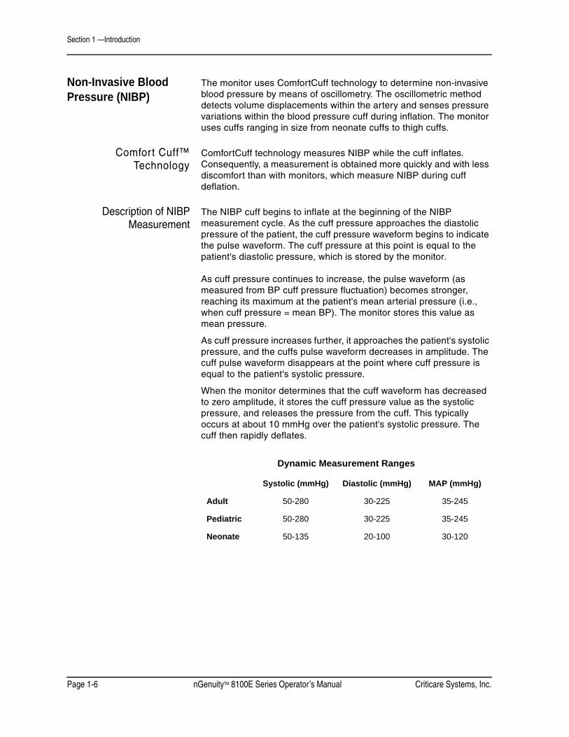
The monitor uses ComfortCuff technology to determine non-invasive blood pressure by means of oscillometry. The oscillometric method detects volume displacements within the artery and senses pressure variations within the blood pressure cuff during inflation. The monitor uses cuffs ranging in size from neonate cuffs to thigh cuffs.
Comfort Cuff™Technology
ComfortCuff technology measures NIBP while the cuff inflates. Consequently, a measurement is obtained more quickly and with less discomfort than with monitors, which measure NIBP during cuff deflation.
Description of NIBPMeasurement
The NIBP cuff begins to inflate at the beginning of the NIBP measurement cycle. As the cuff pressure approaches the diastolic pressure of the patient, the cuff pressure waveform begins to indicate the pulse waveform. The cuff pressure at this point is equal to the patient's diastolic pressure, which is stored by the monitor.
As cuff pressure continues to increase, the pulse waveform (as measured from BP cuff pressure fluctuation) becomes stronger, reaching its maximum at the patient's mean arterial pressure (i.e., when cuff pressure = mean BP). The monitor stores this value as mean pressure.
As cuff pressure increases further, it approaches the patient's systolic pressure, and the cuffs pulse waveform decreases in amplitude. The cuff pulse waveform disappears at the point where cuff pressure is equal to the patient's systolic pressure.
When the monitor determines that the cuff waveform has decreased to zero amplitude, it stores the cuff pressure value as the systolic pressure, and releases the pressure from the cuff. This typically occurs at about 10 mmHg over the patient's systolic pressure. The cuff then rapidly deflates.
Dynamic Measurement Ranges
Systolic (mmHg) Diastolic (mmHg) MAP (mmHg)
Adult 50-280 30-225 35-245
Pediatric 50-280 30-225 35-245
Neonate 50-135 20-100 30-120

Criticare Systems, Inc. nGenuityTM 8100E Series Operator’s Manual Page 1-7
Section 1 —Introduction
NIBP Clinical Testingand Accuracy
This device was clinically tested per the requirements of EN 1060 and AAMI SP-10. The NIBP module as installed in the 8100E series monitor has been tested to meet the performance specifications listed in this manual.
Cuff Inflation andPressure Protection
The maximum cuff inflation rate is 15 mmHg/sec. The software limits inflation to 300 mmHg adult, 300 mmHg pediatric, or 150 neonate. A secondary circuit limits maximum possible cuff pressure to 330 mmHg in adult/pediatric mode and 165 mmHg in neonatal mode. Cuff pressure is allowed to remain above 30 mmHg for a maximum of two minutes.
The monitor automatically deflates the cuff if the time limit is violated. The monitor contains hardware protection for overpressure conditions, pressure transducer failures, or microprocessor and pump control circuit failures.
Figure 1-1: NIBP Cuff Pressure and Pulse over Time
B.P Cuff Inflation Pressure (Shown during inflation)
Systolic Pressure
Actual Blood Pressure Waveform
Diastolic Pressure
Cuff deflates rapidly after monitor determines systolic pressure
Time
Diastolic Pressure
Mean Pressure
Systolic Pressure
Pulse Waveform (Measured from B.P. Cuff Pressure Fluctuation)
Pres
sure
in m
mH
g

Section 1 —Introduction
Page 1-8 nGenuityTM 8100E Series Operator’s Manual Criticare Systems, Inc.
Capnography (Measurement of CO2)
The 8100E Series monitor uses the sidestream method of measuring CO2. Gas is aspirated through a nasal cannula or a ventilation circuit adapter. The gas sample enters from a sampling tube into a water trap, which removes water vapor and particulate matter from the gas sample. The gas then enters the CO2 detector where it is analyzed.
The monitor measures CO2 concentrations and displays them in a continuous waveform. The monitor also detects end-tidal and fraction Inspired CO2 levels, displaying them numerically. End-tidal CO2 (ETCO2) is defined as the maximum CO2 concentration at the end of expiration. The monitor measures and displays this numerical value of CO2 concentration. The ETCO2 value is updated continuously with each breath cycle. The amount of CO2 in the gas mixture inhaled in by the patient is the fractional Inspired CO2 (FICO2).
Method of Measurement The monitor measures CO2 using the principles of infrared absorption spectrometry. An unknown concentration of gas (CO2) is calculated by comparing its absorption of infrared light to that of a known standard. The absorption of light is directly related to the concentration of gas. As infrared light passes through the sample gas chamber, the light transmitted is converted to a voltage signal. The monitor converts the voltage to CO2 concentration and expresses it as mmHg, percent (%), kPa (user selectable), or Torr.
Infrared analysis of the gas samples is done using Beer’s Law.
The formula for Beer’s Law:
Infrared value of measured sample.
Infrared value of light source.
Exponential function.
Extinction coefficient.
Concentration of the gas sample
Distance measured through the sample
The Beer’s Law calculation is performed by the monitor’s software.
I I0 e ε λ( )cd–=I
I0e
ε λ( )c
d

Criticare Systems, Inc. nGenuityTM 8100E Series Operator’s Manual Page 1-9
Section 1 —Introduction
Conditions of Use The 8100E Series monitor has been calibrated with dry NIST-traceable calibration gases at room temperature and pressure (~ 21C, 740mmHg). Given the small effect of water vapor upon the CO2 measurement (see “CO2 Monitoring (Capnography)” in Section 4) and the unit’s built-in temperature and pressure measurements and compensations, this monitor’s method of gas analysis is best described as ATPS (Ambient Temperature and Pressure, Saturated; 21C 750mmHg, 100% Humidity Saturated).
The monitor is suitable for sustained pressure (breathing circuit) monitoring environments and has been tested per clause 51.101 (Measurement Accuracy) of EN 21647: 2004.
Stability of Accuracy The monitor has an internal barometer and thermistor that allow compensation for changes over a range of temperature and atmospheric pressures. The monitor complies with EN 21647 standards for cyclical pressure and testing found negligible drift of accuracy. The module as installed in the 8100E Series monitor has been clinically tested for performance with a variety of patients.
N2O Compensation The monitor has a manual N2O compensation feature for a fixed N2O value of 60%. The user may select N2O compensation when 40-80% N2O is in use.
Temperature Measurement
Body temperature is measured by the monitor using a thermistor (temperature sensing elements in the temperature probe). The thermistor can sense change in body temperature by changing electrical resistance.
• Unusual, fast artificial variations in temperature readings may occur with accompanying applications of an electrocautery system.
• Electrical leakage current of the cable when used with the monitor and sensor comply with IEC 601-1/EN 60601-1.
The monitor is compatible with any YSI-400 or YSI-700 series temperature probe.

Section 1 —Introduction
Page 1-10 nGenuityTM 8100E Series Operator’s Manual Criticare Systems, Inc.
Specifications ECGConnectors: 3 or 5 Lead, Standard AAMI
Lead Selection: 3-Lead; I, II, III5-Lead; I, II, III, aVR, aVL, aVF, V
Gain Selection: 0.5, 1.0, 2.0, 4.0ECG Sensitivity Low 0.5, Medium 1.0, High 2.0,
Frequency Response: Diagnostic; 0.05 - 100 Hz (-3db)Monitor; 0.50 - 40 Hz (-3db)
Electrosurgery Protection: YesHF Equipment Protection: Yes
Defibrillator Protection: YesPacer Detection/Rejection: Yes
Heart RateSource: Smart Switching;
ECG(primary), Pleth, NIBPRange: 20-300 bpm (ECG, Pleth)
30-240 bpm (NIBP)Accuracy: ± 1 bpm or 1% ECG, whichever is greater
(±3 bpm maximum)Pulse Tone: Selectable, On/Off
RespirationSource: ECG, CO2 (primary)
Rate Range: 6 to 150 breaths/minute (ECG)0 to 120 breaths/minute (CO2)
Resolution: 1 breath/minuteAccuracy: ±2 breaths/minute
SpO2Range: 1-99%
Resolution: 1%Accuracy: 70-99% range; ± 2%;
50-69% range; ± 3%<50%; unspecified; Statistical, represents one st. dev. (~66%) of clinical samples.
Indications Plethysmograph, Numerical, Audible (pulse tone pitch varies with SpO2)
Method: Dual wavelength LEDModes: Adult/Pediatric/Neonate
Operation: Continuous UseSensor Wavelength: 660nm/905nm
Sensor Power: <80mW

Criticare Systems, Inc. nGenuityTM 8100E Series Operator’s Manual Page 1-11
Section 1 —Introduction
NIBPTechnique: Oscillometric measure upon inflation
Measurement Time: <40 seconds average; standard adult cuffAutomatic Measurement Cycles: 2, 3, 5, 10, 15, 30 min; 1, 2, 4 hrs
Inflation Pressure Range: Adult; 0 to 300 mmHgPediatric; 0 to 300 mmHgNeonatal; 0 to 150 mmHg
Resolution: 1 mmHgTransducer Accuracy: ± 2 mmHg or 2% of reading, whichever is
greaterSTAT mode: 5 min of consecutive readings
Capnometry (CO2)Units: mmHg; Percent; kPa; Torr
Display: Inspired CO2, Expired CO2 (End-Tidal) Numerical values, capnogram, and breath by breath ETCO2 bar graph.
Method: Non-dispersive Infrared, Auto-calibratingCalibration: Auto-calibrating, Manual Calibration
Waveform Scale: Selectable, percent only0 to 3.13, 6.25, 12.5 or 25%
Range: 0 to 99 mmHg, 0 to 12.5%0 to 12.5 kPa, 0 to 99 Torr
Resolution: 1 mmHg, 0.1%, 0.1 kPa, 0.1 TorrAccuracy: ± 2 mmHg, ±0.3 vol%, ±0.3 kPa, ±2 Torr
@ 200ml/min & RR <=120 Br/minN2O Compensation: Manual (On/Off)
Flow rate: 200 ml/minFlow Tolerance: 200 ml/min, ± 10% (20 ml)
System Response Time: 1.25 seconds @ 200 ml/sec using an 8 ft. sample line
Rise Time: 170 milliseconds @ 200 ml/min (10-90%)Delay Time: 1.08 seconds @ 200 ml/min
Time from cold start: 15 sec. (including auto-calibration) to first reading; 1 min. to full accuracy
Pneumatic Sound Pressure: 35 dBa maximum @ 1 meter
TemperatureChannels: 1
Range: 68° - 113°F, 20° - 45°CAccuracy: ± 0.1°C over entire range
Display Resolution: ± 0.1°CProbe Type: YSI-400 or YSI-700

Section 1 —Introduction
Page 1-12 nGenuityTM 8100E Series Operator’s Manual Criticare Systems, Inc.
AlarmsCharacteristics: EN 475, Adjustable
Indication: Audible; VisualLevels: High, Medium, Low, Informational
Settings: User Defaults, Hospital Defaults, Factory Defaults
Alarm Modes: Adult/Pediatric/Neonate,High and low limit settings for each mode.
Volume: User Adjustable (1-10)Silence: Yes; 2 minutes or permanent
Trend ReportsTypes: Tabular and Graphical
Trend memory: 24 hoursTabular Intervals: 30 sec., 1, 2, 3, 5,10, 15, 30 min., 1, 2, 4
hrs., NIBP (user selectable)Graphical Span: 2, 4, 8, 12, or 24 hours
Data Types: BPM, HR, SpO2, Temp., Resp., NIBP (Systolic, Diastolic, Mean)
Printer (Optional)Recorder Type: Internal thermal line printerData Formats: Single or dual waveform; TabularPaper Speed: 12.5 or 25mm/sec continuous.
(Snapshot at 50mm/sec)
Controls Screen: 10.4" active color TFT
Resolution: 640 x 480 pixelsWaveforms: 6, maximum
Waveform Display Gain: 0.5×, 1×, 2×, 4× user selectableWaveform Sweep Speed: 6.25, 12.5, 25 or 50 mm/sec, selectable
Keys: 9; membrane-activatedRotary knob: Push and rotate; 24 steps/turnLanguages: English, French, German, Portuguese,
Spanish, Italian, Russian
System OutputsCom Ports: RS 232-compatible; digital DB9 (COM 1);
Mini-DIN8 (COM 2)Nurse Call: Contact switch; audio jack 1/8 inch,
24V @ 100 ma maximum switchingDefibrillation Sync: BNC connector
Video Port: Serial VGA Compatible

Criticare Systems, Inc. nGenuityTM 8100E Series Operator’s Manual Page 1-13
Section 1 —Introduction
Mechanical/ElectricalWeight: 13.2 lb; 6 kg (no CO2)
14 lb; 6.4kg (with CO2)Size: 11.0" (H) x 13.0" (W) x 10.3" (D)
28.0cm (H) x 33.1 cm (W) x 26.2cm (D)Mechanical Shock: No affect when tested to IEC 60068-2-27
standardsVibration: No affect when tested to IEC 60068-2-64
standardsPower Requirements: 35W, typical
Voltage: 100 - 240 VAC; 50/60 HzNumber of Batteries: 1 sealed lead acid batteries
Battery Life: 3 hr, typical w/o CO2; 2.5hr, typical w/CO2Recharge time: 4.5 hours
EnvironmentalOperating Temperature: 50° - 104°F, 10° - 40°C
Storage Temperature: 23° - 122°F, -5° - 50°COperating and Storage Humidity: 15% to 90%; non-condensing
Medical Device: Class II Equipment (IIb EU)Electrical Protection: Class I Equipment
Degree of Protection: Type CF, Defibrillator-ProofProtection against ingress: IPX1
Altitude: -1,000 - 10,000 feet
All specifications are subject to change without notice.
Specification related to the ST and Arrhythmia option are found in “Specifications” in Appendix C.

Section 1 —Introduction
Page 1-14 nGenuityTM 8100E Series Operator’s Manual Criticare Systems, Inc.
Symbols Symbol Definition
Refer to Operator’s Manual for Information
Shock Hazard
Equipotential Terminal
European Community Mark
Electrical Testing Laboratories (ETL) Mark
Do not dispose of in municipal waste. Wheeled bin symbol indicates separate collection for electrical and electronic equipment.(WEEE Directive 2002/96/EEC)
Type CF Equipment, defib proof
Identifies the degree of protection against fluid as drip-proof.
Input/Output port
Output only port
Alarm port (Nurse call)
External display port
IPX1

Criticare Systems, Inc. nGenuityTM 8100E Series Operator’s Manual Page 1-15
Section 1 —Introduction
Symbol Definition
Fuse
Gas Scavenging Port
Air Intake
Alternating Current (AC)
Technical Support Phone Number
Serial Number
Part Reference Number
Placement of cuff over the brachial artery. (Blood Pressure Cuff)
Single use device only. Do not reuse.
Recyclable cardboard/paper packaging.
SN
REF
2

Section 1 —Introduction
Page 1-16 nGenuityTM 8100E Series Operator’s Manual Criticare Systems, Inc.
Safety
Definitions Definitions for Warning and Caution symbols:Designates a possible dangerous situation. Non-observance may lead to death or the most severe injuries.
Designates a possible dangerous situation. Non-observance may lead to minor injuries or damage to the product.
Warnings
• Read this manual entirely before attempting clinical use of the monitor.
• Inspect For Damage! User should inspect the system for signs of damage. Do not use the system if failure is evident or suspected.
• Possible explosion hazard! Do not use the monitor in the presence of gas mixtures which may be flammable.
• Do not use this device in conjunction with flammable anesthetics such as cyclopropane and ether. The monitor can sample from pure oxygen environments, but the monitor itself should never be placed inside an oxygen rich environment, such as an oxygen tent or gas containment apparatus. When not in operation, this device is not intended to be connected to any pressurized source containing an enriched oxygen environment.
• All cords must have hospital grade plugs and be plugged into hospital grade outlets. (The electrical installation of the relevant room must comply with NFPA 70: National Electric Code or NFPA 99: Standard for Health Care Facilities. Outside the United States, the relevant room must comply with all electrical installation regulations mandated by the local and regional bodies of government).
• Cables, cords, and leadwires may present a risk of entanglement or strangulation! Verify safe and proper positioning of these items after patient application.
• Leakage currents may increase if other equipment is interconnected to the patient. The increased leakage currents may present a hazard to the patient.
WARNING ! !
CAUTION ! !
WARNING ! !

Criticare Systems, Inc. nGenuityTM 8100E Series Operator’s Manual Page 1-17
Section 1 —Introduction
• High Frequency (HF) surgical equipment may affect ECG operation. The ECG waveform will return to normal momentarily after the HF source is removed. Ensure that electrodes and sensors are not placed near the HF source.
• Unapproved modifications to the monitor may cause unexpected results and present a hazard to the patient. Unapproved use of the accessories can also present a hazard to the patient or affect monitor performance.
• Do not re-use accessories labeled as single use. Risk of patient contamination may occur.
• Improper disposal of batteries may result in explosion, leakage, or personal injury. Do not open batteries. Do not dispose of batteries in a fire. Follow all local regulations concerning the disposal of spent Lead-acid and Lithium-Ion batteries or contact Criticare for assistance.
• Risk of electrical shock! Do not remove cover. Refer servicing to qualified personnel.
• U.S. Federal law restricts this device to sale by or on the order of a physician.
Cautions
• Use the monitor only with recommended accessories! Use of unapproved accessories may cause inaccurate readings.
• Equipment accuracy may be affected at extreme temperatures.
• Do not store equipment at extreme temperature. Temperatures exceeding specified storage temperatures could damage the system.
• A possible explosion hazard exists! Do not use the monitor in the presence of flammable anesthetics.
• Do not press on the keys with surgical instruments or other tools. Sharp or hard objects could damage the keys. Use only your fingertips to press on the keys.
• Do not allow the conductive parts of the patient electrodes to contact other conductive parts, including ground (earth).
• Changes or modifications not expressly approved by Criticare Systems, Inc., may void the user's authority to operate the equipment and may also void the warranty.
• Always monitor patients with a pacemaker very closely, since the 8100E may count at the pacemaker rate during cardiac arrest or some arrhythmias.
WARNING ! !
CAUTION ! !

Section 1 —Introduction
Page 1-18 nGenuityTM 8100E Series Operator’s Manual Criticare Systems, Inc.
Leakage Current The monitor complies with leakage current limits required by medical safety standards for patient-connected devices. A hazard caused by the summation of leakage currents is possible, when several pieces of equipment are interconnected.
Connecting any external equipment to signal input, signal output, or other connectors forms a system and this new system must comply with the requirements of IEC 60601-1-1. If in doubt, contact qualified technician or local representative.
Voltage Fluctuations When operated in the line voltage range specified in this manual any fluctuation will have a negligible effect. Very low line voltage will cause the monitor to revert to battery power. Very high line voltage may cause damage to the charger circuits. The monitor is designed with circuitry that turns the unit off before spurious readings can be caused by a low battery condition.
Equipotential Ground Health care providers and patients are subject to dangerous, uncontrollable compensating currents for electrical equipment. These currents are due to the potential differences between connected equipment and touchable conducting parts as found in medical rooms.
The safety solution to the problem is accomplished with consistent equipotential bonding. The monitor is fitted with a connecting lead made up with angled sockets to the equipotential bonding network in medical rooms.
Software Error RelatedHazard Mediation
Criticare Systems, Inc., has quality control practices and procedures in place to review potential hazards as they relate to software. The monitor is Year 2000 Compliant and utilizes a 4 digit year for all date, time, and leap year calculations.
Connection Lead (Socket)
Equipotential Connector
Equipotential Terminal
Main Body
Earth Ground

Criticare Systems, Inc. nGenuityTM 8100E Series Operator’s Manual Page 1-19
Section 1 —Introduction
Potential Interference This device has been successfully tested to IEC 601-1-2 specified levels for emissions of and resistance to electromagnetic energy fields. External disturbances which exceed these levels may cause operational issues with this device. Other devices which are sensitive to a lower level of emissions than those allowed by IEC 601-1-2 may experience operational issues when used in proximity to this device.
MAGNETIC FIELDSUse of the monitor in an MRI environment may interfere with MRI image quality. Use of MRI may interfere with the monitor.
The 8100E Series patient monitor is not intended for use in MRI environments.
RADIO FREQUENCY INTERFERENCEThe monitor conforms with IEC 1000-4-3 for radio frequency interference, and will operate with negligible adverse effects.
CONDUCTED TRANSIENTSThe monitor conforms with IEC 61000-4-4, and IEC 61000-4-5 for conducted transients, and will operate with negligible adverse effects.
X-RAYThe monitor will operate with negligible adverse effects in an X-ray environment. However, the monitor should not be placed directly in the X-ray beam, which could damage the internal electronics of the monitor.
OTHER INTERFERENCEThere is a negligible adverse effect to the monitor from electrocautery and electrosurgery, infrared energy, and defibrillation.
Biocompatibility All patient-contact or user-contact materials in this monitor and it's accessories have passed ISO 10993-5, -10, & -11 biocompatibility tests or have been in use in clinical environments in large numbers over an extended period of time predating these standards.
Latex Content All Criticare Systems, Inc., products, including patient monitors and accessories, are free from latex in any location that may result in patient contact.
DEHP Content All Criticare Systems, Inc., products currently shipping are free of DBP and DEHP in any areas that would be intended for patient contact with blood, mucous membranes, or continuous skin/tissue contact.

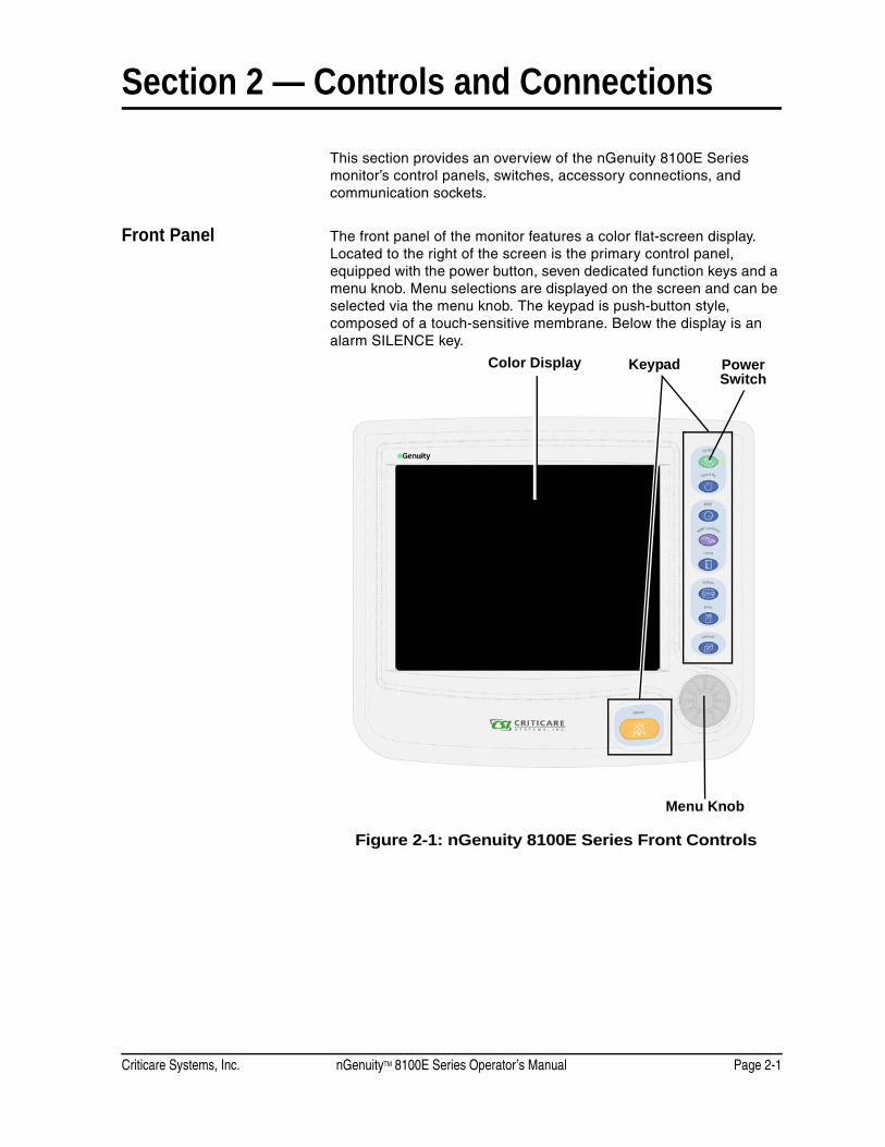
Criticare Systems, Inc. nGenuityTM 8100E Series Operator’s Manual Page 2-1
Section 2 — Controls and Connections
This section provides an overview of the nGenuity 8100E Series monitor’s control panels, switches, accessory connections, and communication sockets.
Front Panel The front panel of the monitor features a color flat-screen display. Located to the right of the screen is the primary control panel, equipped with the power button, seven dedicated function keys and a menu knob. Menu selections are displayed on the screen and can be selected via the menu knob. The keypad is push-button style, composed of a touch-sensitive membrane. Below the display is an alarm SILENCE key.
Figure 2-1: nGenuity 8100E Series Front Controls
Color Display
Menu Knob
Power Switch
Keypad

Section 2 —Controls and Connections
Page 2-2 nGenuityTM 8100E Series Operator’s Manual Criticare Systems, Inc.
Keypad There are nine (9) keypad buttons, including the ON/OFF key and the eight (8) dedicated function keys. Some of the keys have two (2) functions. The primary function is activated with a momentary press of the key. A secondary function, if present, is activated when the key is pressed and held for two seconds.
Key Function
On/Off Power key. Press to activate the patient monitor and press and hold to turn the monitor off.
Stand By Press this key momentarily to enter standby mode. Press the key again to exit the standby mode.
NIBP NIBP measurement start key. Press the key again to cancel a NIBP measurement.
NIBP Cycle/Stat Press the key momentarily to display the NIBP cycle popup menu on the screen. Press and hold this key to begin a Stat measurement.
Trend Displays the trend table when pressed momentarily. Press the key to exit the trend window. While the trend table is displayed, press and hold to access the trend settings menu.
Freeze Freezes all waveforms on the screen. Numerical parameters continue to be updated. Press the key again to resume continuous waveform display.
Print Press this key to begin printing or serial output. Press the key again to stop printing.
Default Press this key momentarily to access custom default profiles. Press and hold the key to alter custom default profiles (password LIA6Ø8 required).
Silence Press this key momentarily to begin a two minute alarm silence. Press and hold the key to permanently silence the alarms. Press the key again, a second time, to resume normal alarms.
An audible beep notifies the user that a primary function has been activated. A double beep notifies the user that a secondary function has been selected by pressing and holding the key.

Criticare Systems, Inc. nGenuityTM 8100E Series Operator’s Manual Page 2-3
Section 2 —Controls and Connections
AC Power Indicator A green LED indicator is located to the right of the ON/OFF (power) key. The indicator is on if AC power is present.
Figure 2-2: Detail of Right Side of Front Panel
Rotary Menu Knob The knob can be turned left or right to make selections from any of the menus that appear on the front display. The selected menu option can then be activated by pressing in on the knob.
Color Display The display provides real-time waveform data and numerical data of the measured parameters. The display screen provides main-screen menu options that are selected and activated by the menu knob. Additional menus that appear on the display screen are also selectable with the menu knob.
AC Power Indicator
Function Keys
Rotary Menu Knob
Col
or
Dis
play

Section 2 —Controls and Connections
Page 2-4 nGenuityTM 8100E Series Operator’s Manual Criticare Systems, Inc.
Left Side Panel The left side of the monitor has four connections for patient monitoring. The electrocardiogram (ECG), pulse oximetry (SpO2), temperature, and the non-invasive blood pressure (NIBP) measuring connections are standard on all nGenuity models.
• The ECG uses an AAMI-standard circular 6-contact connector located at the top.
• One female, 1/4 inch, YSI temperature cable socket is located below the ECG connector.
• The DB-9 female serial connector is used for SpO2 sensor connection.
• A male quick-connect style NIBP fitting is located at the bottom on the left side.
More information about accessory connections can be found in “Patient Monitoring” in Section 4 of this manual.
Figure 2-3: Left Side
ECG
Temperature
SpO2
NIBP

Criticare Systems, Inc. nGenuityTM 8100E Series Operator’s Manual Page 2-5
Section 2 —Controls and Connections
Water Trap and SamplingLine Connection
The water trap connection is an optional model feature. The water trap is located on the left panel toward the rear of the unit. The sampling connection is made at the connector on the front of the water trap and is used for CO2 monitoring. The sampling line is a standard female Luer-lock connector when using the WaterChek™2+ water trap accessory.
NOTE: Other water traps in the WaterChek™ series are compatible with this monitor. Some older versions used a male Luer-lock sampling line connection on the water trap.
Figure 2-4: Left Side with Water Trap
ECG
Temperature
SpO2
NIBP
Water Trap

Section 2 —Controls and Connections
Page 2-6 nGenuityTM 8100E Series Operator’s Manual Criticare Systems, Inc.
Rear Panel and Fixtures
Figure 2-5: Rear View
NOTE: Service access panels, fuse panels, and the chassis ground are discussed in the service literature for the monitor. There are no user procedures necessary for these items during normal operation of the monitor.
NOTE: Some communications connections may have protective covers that need to be removed before use.
AC Power Connection
Chassis Ground
Communication Connections
Service Access Panel
Fuse Access Panel
Printer (Optional)
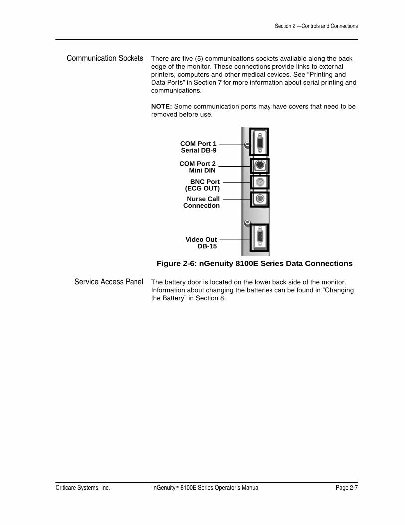
Criticare Systems, Inc. nGenuityTM 8100E Series Operator’s Manual Page 2-7
Section 2 —Controls and Connections
Communication Sockets There are five (5) communications sockets available along the back edge of the monitor. These connections provide links to external printers, computers and other medical devices. See “Printing and Data Ports” in Section 7 for more information about serial printing and communications.
NOTE: Some communication ports may have covers that need to be removed before use.
Figure 2-6: nGenuity 8100E Series Data Connections
Service Access Panel The battery door is located on the lower back side of the monitor. Information about changing the batteries can be found in “Changing the Battery” in Section 8.
COM Port 1Serial DB-9
COM Port 2Mini DIN
BNC Port(ECG OUT)Nurse Call
Connection
Video OutDB-15

Section 2 —Controls and Connections
Page 2-8 nGenuityTM 8100E Series Operator’s Manual Criticare Systems, Inc.
Figure 2-7: nGenuity 8100E Series Power Panel
Chassis Ground This is used during testing and servicing of the unit. See the nGenuity 8100E Series Service Manual (CAT 1448) for more information about testing.
AC Power CableConnection
An AC power cable connection is located at the center of the rear of the patient monitor. The cable plug is placed in the socket and the cord can be fit into the channel provided in the case.
Fuse Access Panel The fuses are located behind this panel.
Optional Printer This printer door provides quick access to the internal printer paper spool. The printer lever releases the printer rollers for removing jammed paper. The knob can be turned to feed paper. See “Printing and Data Ports” in Section 7 for additional printer information.
AC PowerCable
Connection
Chassis Ground
FuseAccess
Panel
Criticare Systems, Inc. nGenuityTM 8100E Series Operator’s Manual Page 2-9
Section 2 —Controls and Connections
Screen Display and Interface
The display is divided into several areas that are dedicated to different types of data and interface functions. The upper left corner contains six (6) slots for displaying continuous waveform data or graphs. The waveforms are user selectable and can be user configured. The silence icon for the silence mode (2 minute or permanent) is shown in the upper right corner of the top waveform slot.
The right column provides space for the reporting of physiological parameter data in numerical form. Each parameter has a selectable color for the parameter numerical data that matches the color of the waveform displayed in the slots. Numerical parameters for NIBP are reported below the waveform slots and for temperature are reported above the date and time on the screen.
Heart rate is fixed to Parameter Slot 1 and Temperature is fixed to Slot 6 when turned on. Slot 5 is used for NIBP parameters when assigned a function. Slots 2-4 will display Respiration, SpO2 and CO2 in that order from top to bottom (if functions are active) unless waveform slots have been assigned a different order in which case the parameter slots will match the corresponding waveforms.

Section 2 —Controls and Connections
Page 2-10 nGenuityTM 8100E Series Operator’s Manual Criticare Systems, Inc.
The bottom portion of the display has space dedicated to the following message types and functions.
• The main screen menu of selectable softkeys.
• Two (2) message lines for alarms and alerts.
• A system status line for battery status and patient size mode.
• Data from temperature monitoring.
• The patient information bar and date/time clock.
Figure 2-8: Screen Diagram
NIBP Parameters
Waveform Slot 1
Waveform Slot 2
Waveform Slot 3
Waveform Slot 4Waveform Slot 5
Waveform Slot 6
ALARMS PARAMSADM/DIS
DISPLAYCONFIG PRINT
Priority AlarmsInfo MessagesSystem Status
Patient Data TimeDate
Parameter Slot 1
Parameter Slot 2
Parameter Slot 3
Parameter Slot 4
Parameter Slot 5
Parameter Slot 6Temperature (if on)
NIBP (if not in use)
Heart Rate

Criticare Systems, Inc. nGenuityTM 8100E Series Operator’s Manual Page 2-11
Section 2 —Controls and Connections
NOTE: Your screen may appear different from below based on waveforms selected and their chosen slots.
Figure 2-9: Sample Interface Screen
Waveform Slots The waveform area is located in the upper left hand corner of the display. The monitor has the capability to display six (6) waveforms simultaneously.
The waveforms that can be displayed are user selectable, with the exception of the first waveform which is locked into being an ECG waveform; the lead type is user selectable.
Each waveform slot displays the parameter or source vertically along the left edge of the screen. Amplitude bar and range are shown at the beginning of the slot if applicable to that type of waveform. Each parameter’s waveform is shown in a selectable color. The waveforms can be cascaded to fill multiple slots and slots can be combined to form double high waveforms. See “Cascaded Slots” in Section 3 for details.
ALARMS PARAMS DISPLAYALARMS PARAMS DISPLAY
AdultAdultV000 - NO ADMITV000 - NO ADMITSPO2: SENSORSPO2: SENSOR
ADM/DIS CONFIG PRINTADM/DIS CONFIG PRINTAUG-07-05 14:12:59AUG-07-05 14:12:59
SpO2SpO2
IIII
%
CO2CO2
MAP mmHgMAP mmHg CYCLE OFFCYCLE OFF
1mV1mV BPMBPM
Br/mBr/m
6060
9898
97.797.7
2020
- +- +
149/106149/106 (127)(127) AGE 01:00 AGE 01:00
Fo
ECGECGRESPRESP
SYS DIASYS DIA
Low SpO2 Alarm 90%
mmHgmmHg5.05.0INSINS
CO2CO2
EXPEXP
1.11.1
ECG:ALARM MESSAGE
NIBP:ALARM MESSAGE

Section 2 —Controls and Connections
Page 2-12 nGenuityTM 8100E Series Operator’s Manual Criticare Systems, Inc.
The color of each channel can be selected independently. See “PARAMS Softkey (Physiological Parameters)” in Section 3.
If the waveform pulses exceed the limit of the selected range for the waveform, the waveform is clipped.
VISUAL ALARMS WITH WAVEFORMSThe waveform slots are also used to display physiological alarms that appear at the top center of each slot. For a high priority alarm the color of the message is red. For a medium priority alarm, the color of the message is yellow.
The bottom five (5) slots may be covered by menus and messages. Since the top waveform slot is dedicated to ECG, the ECG waveform and the ECG high and medium priority messages are always visible if ECG is currently being monitored and the top slot is active.
See “Visible Alarms” in Section 5 for a complete description of visual alarms.
SILENCE ALERT STATUSThe silence alert visual icon appears in the upper right corner of the top waveform. The silence icon shows a bell with an "X" and an infinity symbol when the Alarm SILENCE hard key is pressed and held for more than two seconds. The Alarm Suspend icon shows a bell with an "X" and the words 2 min when the Alarm SILENCE hard key is momentarily pressed.
ECG WAVEFORMThe lead type are displayed in the top left corner of each slot set to for ECG waveforms. The amplitude bar, shown in white, indicates the scale for 1mV positive and negative.
When the pacer detection feature is enabled, the pacer spikes in the ECG waveform are shown in white.
IMPEDANCE RESPIRATION WAVFORMThe impedance respiration waveform is based upon the ECG data. The label ECG RESP appears at the beginning of the waveform. The impedance respiration derives its color from the ECG color setting to indicate that it is sourced from ECG. The waveform is auto ranging where the monitor attempts to keep the waveform centered in the slot at all times.
SPO2 WAVEFORMThe waveform is auto ranging where the monitor attempts to keep the waveform centered in the slot at all times. No amplitude bar is shown.

Criticare Systems, Inc. nGenuityTM 8100E Series Operator’s Manual Page 2-13
Section 2 —Controls and Connections
CO2 WAVEFORMThe CO2 waveform, capnogram, is always displayed in percent regardless of the units selected for displaying the numerical data. The maximum range of the capnometer waveform is 25%.
BREATH BY BREATH BAR GRAPH (BXB)The label “BxB” appears at the beginning of the graph. The user may select the CO2 data to be displayed as a breath by breath bar graph. The breath by breath data always displays in percent. The maximum range of the capnometer bar graph is 25%.
Numerical ParameterBoxes
The numerical parameter box area is directly to the right of the waveform area. The area is broken into four (4) numerical boxes. These numerical parameter boxes align the numerics with the waveforms of a particular parameter. There is an additional elongated numerical parameter box below the waveforms for NIBP data. Another numerical parameter box to the right of the message and status lines displays temperature numerical data.
If a module is turned off in the PARAMS menu, the numerical parameters are not shown. Smart parameters such as respiration and heart rate switch to another available module if possible.
ECG BOXThe top parameter box, in the upper right hand corner, is dedicated to display the heart rate. The source of the heart rate (i.e. ECG, SpO2, or NIBP) is shown in the upper left. The color of the heart rate numerics changes to match the color assigned to the source.
A bell icon appears in the lower right corner of the box if either heart rate alarm limit is set to off. The bell icon is red with a white “X” indicating that an alarm is turned off.
RESPIRATION BOXThe Respiration box displays the respiration rate and a bell icon if the respiration alarm is set to OFF.
SPO2 BOXThe SpO2 box displays the oxygen saturation in percent. A bell icon, in the right center, is shown if an oxygen saturation alarm limit is set to off. Below the SpO2 value is a message stating what the set value is to initiate a Low SpO2 Alarm. This value is set in the ALARMS menu.
CO2 BOXThis box displays numerical values for the inspired and expired CO2. The label EXP stands for expired (end-tidal) CO2 and INS stands for inspired CO2. The current units for CO2 display in the upper right corner.
BPMBPM
6060Br/mBr/m2020%%9898
Low SpO2 Alarm 90%
INSINS
5.05.0EXPEXP
1.1
CO2CO2
mmHgmmHg

Section 2 —Controls and Connections
Page 2-14 nGenuityTM 8100E Series Operator’s Manual Criticare Systems, Inc.
NIBP BOXThe NIBP numerical box is located below the waveforms. It displays the systolic, diastolic, and mean pressure after a NIBP reading has completed. The systolic and diastolic values are shown in large text. The mean value (MAP) is displayed to the right of the systolic and diastolic values in smaller characters. MAP values are shown in parenthesis.
When there is no valid reading, dashes are displayed. A valid reading is dashed after 30 minutes. If a valid reading is being displayed, the age of the reading is displayed. After 30 minutes the age of the measurement goes to dashes; if there is no valid reading, the age also appears as dashes.
If a cycle time has been set, the interval is displayed. Otherwise the cycle time displays the word OFF in the NIBP box. If a cycle time is active, the amount of time remaining until the next NIBP reading is scheduled is displayed at the bottom right of the box. Also, a bell icon is displayed on the right side of the box to show if any NIBP alarm limit is set to off.
When the monitor is taking an NIBP reading the MAP designation becomes a CUFF designation to indicate that a reading is in progress. When the reading is completed, the CUFF designation returns to MAP.
TEMPERATURE BOXThe temperature numerical box is dedicated to the temperature channel. The units (°F or °C) appear in the upper right corner of the box. A bell icon appears below the unit label if an alarm limit is set to OFF.
MAP mmHgMAP mmHg CYCLE OFFCYCLE OFF
149/106149/106 (127)(127) AGE 01:00 AGE 01:00
SYS DIASYS DIA
CUFF mmHgCUFF mmHg CYCLE OFFCYCLE OFF
149/106149/106 (127)(127) AGE 00:10 minAGE 00:10 min
SYS DIASYS DIA
97.797.7Fo

Criticare Systems, Inc. nGenuityTM 8100E Series Operator’s Manual Page 2-15
Section 2 —Controls and Connections
Main Menu The main menu area is directly under the help NIBP box on the left-hand side of the screen. There are up to six (6) selectable soft keys located on the screen as shown below.
Figure 2-10: Main Menu
One of the six (6) softkeys is always highlighted. If the user pushes the rotary knob any window associated with the highlighted softkey is displayed and the rotary knob control goes to that new window. Different soft keys are selected by turning the rotary knob clockwise or counterclockwise until the desired key is highlighted.
When the softkeys are not being accessed, they disappear from the screen after 45 seconds if inactivity. Turn or push the rotary knob to display the softkeys.
More information about the soft keys and their function is explained in “Softkey Functions (Main Menu)” in Section 3.
Alarm and Message Areas The two (2) alarm lines are located under the NIBP numerical box. All NIBP and temperature parameters have all of their alarm/error messages displayed in this area. ECG, SPO2, and respiration high and medium alarms are displayed here if there is not an active waveform associated with them. All low level messages are displayed in the top alarm line. The bottom line is for informational messages and advisory level alerts only.
The informational, low, and medium level alarm warnings are colored yellow and the high alarm warning messages are red. For more information about alarms see “Alarms and Messages” in Section 5.
System Status Box The system status box is located directly below the two lines reserved for alarms and messages.
BATTERY WARNING ICONThere is space reserved for one battery icon. The battery icon represents the state of the internal rechargeable battery. See “Battery Indicators” in Section 3 for a complete description of the icon and battery charging.
PATIENT SIZE MODEThe next item in the status line is the patient mode. This message lets the user know what the patient size or mode the system is in: Adult, Pediatric, or Neonate. The default physiological alarm limits may change depending on which mode is currently in use.
ALARMS PARAMS DISPLAY
ADM/DIS CONFIG PRINT
Section 2 —Controls and Connections
Page 2-16 nGenuityTM 8100E Series Operator’s Manual Criticare Systems, Inc.
Patient Informationand Clock
A Patient Information Bar runs along the bottom of the display. This area displays the last name (12 characters), the first name (10 characters) and middle initial (one character) of the patient, the hospital identification number for the patient (16 characters), and the patient's room number (five characters).
The current date and time appear to the extreme right of the patient information.

Criticare Systems, Inc. nGenuityTM 8100E Series Operator’s Manual Page 3-1
Section 3 — Setup Procedure
Monitor Setup This section provides an overview of the setup procedures for nGenuity 8100E Series monitor.
The monitor should be set up by the health care provider before using it on patients. If the monitor is new, preparations such as loading paper and batteries should be performed. See “Changing the Battery” in Section 8 for battery changing instructions. For monitors with the optional internal printer see the paper loading instructions in “Changing Printer Paper” in Section 7.
Battery Power The monitor has one (1) rechargable lead acid battery.
Charging the Monitor The monitor has an internal battery charger and charges the battery whenever the AC cord is plugged in, including while the monitor is in use. The green AC (mains) power indicator light should illuminate when the power cord is plugged in correctly. If the green light is not on, check the connections and the power socket for malfunctions.
• If the electrical integrity of the earth ground is in doubt, the power cord should be disconnected and the machine should be operated from its internal electrical power source.
• Explosion hazard. Keep lighted cigarettes, sparks, and flames away from the battery.
• The battery contains sulfuric acid electrolyte which can cause severe burns and eye damage, as well as illness from sulfur oxide fumes.
• Do not short circuit the battery terminals. The resulting high-current discharge can cause burns.
The monitor functions if plugged into AC (mains) power even while the battery is completely drained. A defective battery should not be left inside the monitor. The monitor can also function without the battery, running on AC power only, but this is not recommended in a clinical setting.
The battery should be allowed to charge to full strength before using. If the battery is not fully charged before use, the battery does not hold as much charge in the future. Insufficient charging also degrades and shortens the life of the battery.
WARNING ! !

Section 3 —Setup Procedure
Page 3-2 nGenuityTM 8100E Series Operator’s Manual Criticare Systems, Inc.
Battery Indicators The battery icon is located on the lower portion of the main screen as described in “Screen Display and Interface” in Section 2. The battery icon changes color to indicate the status of the battery. The battery icon appears when using DC (battery) power or when using AC (mains) power.
Orange Battery is charging.Green Battery is fully charged.Yellow Battery is weak. (< 30 min. of charge remain)Black Battery is nearly drained. (< 15 min. of charge remain)
When the battery icon is yellow or black, the internal printer does not function. Recharge the battery and/or connect the monitor to AC before attempting to use the printer.
When the icon is black, the monitor cannot perform NIBP readings. Recharge the battery and/or connect the monitor to AC before attempting to take NIBP readings.
While using battery power there is a short delay between a change in battery status and the updated display of the battery icon.
If the monitor is currently operating under AC power, the monitor may take up to two minutes to display a change in battery status.

Criticare Systems, Inc. nGenuityTM 8100E Series Operator’s Manual Page 3-3
Section 3 —Setup Procedure
System Start and Auto-calibration
Press the power (ON/OFF) key, located at the top of the front control panel, to start the monitor.
Immediately upon power up, the monitor displays the title screen with the CSI logo. The software revision appears in the lower left corner of the splash screen. The monitor also activates a paper feed if the monitor has an internal printer.
• The informational message NO ADMIT displays indicating that no patient is currently identified for wireless or network communication purposes. Communication setup is not necessary for general use. Contact Criticare customer service for information about using wireless communication or networks.
• Audible alarms are suspended for each parameter until the first valid measurement has been taken for each parameter. Visual alerts are always active.
• If a patient had been previously admitted by the monitor, a notice message RESUME MONITORING appears in a yellow box. Press the knob to continue monitoring with the current patient. Select NO to change patient.
The monitor is composed of several technology modules that measure different physiologic parameters. Some modules such as the oximeter are ready for use within seconds of powering up.
Sensor and ProbeMessages
Depending on the accessories attached to the monitor upon start up, various messages concerning detached sensors and probes appear. These are only visual alarms until valid measurements are taken by the accessories, after which a low level alarm sounds when the sensors and probes are disconnected.
If sensor and probe messages from unused modules become a distraction, the messages disappear if the module is turned off. The OFF settings are located in the PARAMS windows described in “PARAMS Softkey (Physiological Parameters)” in this Section.
Section 3 —Setup Procedure
Page 3-4 nGenuityTM 8100E Series Operator’s Manual Criticare Systems, Inc.
CO2 Calibration 8100E Series monitors may have an optional internal capnometer. During setup the monitor may attempt to calibrate the capnometer. The internal capnometer has unique calibration warning messages as described below:
• Monitoring modules such as the internal capnometer require an initial auto-calibration at power up. A short warm-up period may also be necessary in very cold start up conditions. CO2 monitoring and associated audible alarms are suspended during auto-calibration. The auto-calibration cannot be canceled during initial power up.
• Approximately five (5) seconds after power up, the monitor performs an auto-calibration lasting about 10 seconds.
NOTE: This does not occur for monitors that do not have the CO2 module or when the module is turned off in the PARAMS menu.
• The message CO2: ZEROCAL appears on the display during calibration. The monitor then automatically begins monitoring CO2 values if the CO2 module is turned on in the setting and provided a breath is detected.

Criticare Systems, Inc. nGenuityTM 8100E Series Operator’s Manual Page 3-5
Section 3 —Setup Procedure
Softkey Functions (Main Menu)
Softkeys are selected by turning the rotary knob clockwise or counterclockwise until the desired softkey is highlighted. In the sample below the ALARMS softkey is highlighted indicating that the alarm settings window will be displayed if the menu knob is pressed.
Figure 3-1: Main Menu
If the knob is rotated, any window associated with the highlighted softkey is displayed when the knob is pressed. The knob then controls scrolling through that new menu window.
The top item (EXIT) on each menu window is automatically highlighted when the window is activated. The user may simply press the menu knob a second time to exit each window without making changes.
At the bottom of the window there may be selections allowing access to subordinate windows. Some windows and settings discussed in this manual may not be present if the feature is not installed in the monitor. If a parameter has been turned OFF in the PARAMS window, settings in other windows, such as alarm limits, may be disabled.
Changing Settings Turn the rotary knob to highlight items on these menu windows. Press the knob to select the item. A single short beep is generated. The key press beep is audible even when the alarms are silenced.
Some of the settings require an alpha/numeric entry. Rotate the knob to the desired character and press to select. The cursor will automatically move to the next space.
If an error is made while entering, a left arrow character can be selected in order to back over the existing text. The down arrow character can be selected to jump to the next line.
The arrow characters are not available when entering passwords.
ALARMS PARAMS DISPLAY
ADM/DIS CONFIG PRINT

Section 3 —Setup Procedure
Page 3-6 nGenuityTM 8100E Series Operator’s Manual Criticare Systems, Inc.
Saved Setting Profiles Alarms and parameter default settings may be independently modified as part of a customized default profile. Setting changes generally remain after the monitor is power cycled.
• Changes made to the settings remain in current memory until a patient is discharged or the monitor is left without power.
• If the monitor loses its current setting it returns to the last profile selected from the memory. If no profile has ever been selected, initially, it is CUSTOM DEFAULTS and it begins with the same settings as the Factory Default Settings listed at the end of this section.
• The permanent Factory Default profile can be accessed and restored in the CONFIG window.
• The user defined profiles can be accessed and restored by pressing the DEFAULT key.
See “Alternative Care Defaults” in Appendix B for instructions for loading ALTERNATE CARE defaults.
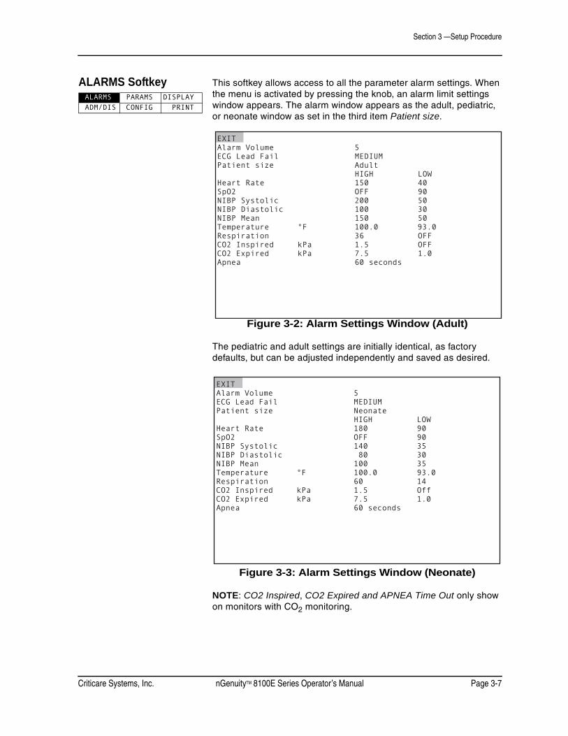
Criticare Systems, Inc. nGenuityTM 8100E Series Operator’s Manual Page 3-7
Section 3 —Setup Procedure
ALARMS Softkey This softkey allows access to all the parameter alarm settings. When the menu is activated by pressing the knob, an alarm limit settings window appears. The alarm window appears as the adult, pediatric, or neonate window as set in the third item Patient size.
Figure 3-2: Alarm Settings Window (Adult)
The pediatric and adult settings are initially identical, as factory defaults, but can be adjusted independently and saved as desired.
Figure 3-3: Alarm Settings Window (Neonate)
NOTE: CO2 Inspired, CO2 Expired and APNEA Time Out only show on monitors with CO2 monitoring.
ALARMS PARAMS DISPLAY ADM/DIS CONFIG PRINT
EXITAlarm Volume 5ECG Lead Fail MEDIUMPatient size Adult HIGH LOWHeart Rate 150 40SpO2 OFF 90NIBP Systolic 200 50NIBP Diastolic 100 30NIBP Mean 150 50Temperature °F 100.0 93.0Respiration 36 OFFCO2 Inspired kPa 1.5 OFFCO2 Expired kPa 7.5 1.0Apnea 60 seconds
EXITAlarm Volume 5ECG Lead Fail MEDIUMPatient size Neonate HIGH LOWHeart Rate 180 90SpO2 OFF 90NIBP Systolic 140 35NIBP Diastolic 80 30NIBP Mean 100 35Temperature °F 100.0 93.0Respiration 60 14CO2 Inspired kPa 1.5 OffCO2 Expired kPa 7.5 1.0Apnea 60 seconds

Section 3 —Setup Procedure
Page 3-8 nGenuityTM 8100E Series Operator’s Manual Criticare Systems, Inc.
Alarms Settingsby Patient Size
The monitor retains separate alarm setting for three different patient sizes. When the patient size mode is changed to adult, pediatric, or neonate, the monitor recalls alarm limit setting specific to each patient size.
The extended alarm limit window, which is present for monitors with ST/Arrhythmia, also has size specific versions. As in the main the screen, the pediatric alarm settings are the same as adult in the Factory Default profile. See “Arrhythmia and ST Analysis” in Appendix C.
To set all the alarm limits, adjust the settings as necessary including the extended windows that appear under Other Alarm Setups. Then change to the next patient size and adjust the settings again including the extended windows. Repeat again with the last patient size to complete the setting of all alarm limits.
Alarm Limits Alarms activate when a high alarm limit is exceeded or the measured value drops below a low alarm limit. High and Low limit values can be set to the same values. In such a case, the monitor alarms when any value, but the selected value is measured.
• Turning an alarm limit off disables both the audible and visual portion of the alarm.
• Some alarms automatically reset when the monitor is power cycled. See “Alarms at Start Up” in Section 5 for details.
The low limit alarm can never be set higher than the high limit alarm. The high limit adjustment is similarly restricted. When adjusting limit values some of the range may not be available because the monitor does not display ranges beyond the point that the other limit is set.
Alarm limits cannot be changed for monitoring modules that have been turned off. If an alarm limit cannot be selected, check the PARAMS menu to confirm the module is turned on.
ECG Lead Fail This is an adjustable alarm level setting for a condition where the monitor cannot detect connected ECG leads. Set this according to the protocols of the facility or to the specific patient need.
CAUTION ! !

Criticare Systems, Inc. nGenuityTM 8100E Series Operator’s Manual Page 3-9
Section 3 —Setup Procedure
Alarm Volume The alarm volume can be set from 1 to 10. If the volume is set to 1 it returns as 2 if the monitor is power cycled. To turn off the alarms use the SILENCE key. See “Alarms and Messages” in Section 5 for more information about alarms.
Low SpO2 Alarm The setting for the Low SpO2 Alarm displays in the SpO2 parameter box on the display.

Section 3 —Setup Procedure
Page 3-10 nGenuityTM 8100E Series Operator’s Manual Criticare Systems, Inc.
PARAMS Softkey (Physiological Parameters)
When this key is activated a parameter settings window appears. This softkey allows access to the physiological parameter settings. Each of the sampling modules is listed here and can be turned on and off.
NOTE: CO2 parameters will only show on monitors with CO2 monitoring.
Figure 3-4: Parameter Window
HR Source(Smart Heart Rate)
Turning off modules forces the monitor to generate the numerical heart rate value from the remaining operating modules. If the ECG signal is lost or turned off, the monitor automatically switches to an SpO2 source for heart rate if SpO2 is available.
The monitor generates a heart rate from the ECG module, the SpO2 module, or from the NIBP in that order of preference. The NIBP heart rate is updated with each NIBP measurement rather than being continuously updated with the ECG or SpO2 waveform data. When the heart rate is based on NIBP data the numerical heart rate value is removed two minutes after the last NIBP measurement is completed.
ECG Settings Cable can be set to 3 lead or 5 lead. The default is 5 lead. Pace Detect can be set to ON or OFF. The default is OFF. Sensitivity can be set to LOW, MEDIUM, or HIGH. The default is MEDIUM. See “Filter Settings” in this section for details on Filter settings.
ALARMS PARAMS DISPLAY ADM/DIS CONFIG PRINT
EXIT
Heart Rate NIBP ON ¤ HR Source Smart NIBP tone NONE Heart Rate Tone Vol 5 Temperature ON ¤ ECG ¤ Unit of measure F Cable 3-lead Pace detect OFF Filter Monitor Sensitivity MEDIUM SpO2 ¤ Average 12 seconds Search time 20 seconds
Respiration ON
CO2 OFF ¤ Unit of measure kPa N2O Compensation OFF
o

Criticare Systems, Inc. nGenuityTM 8100E Series Operator’s Manual Page 3-11
Section 3 —Setup Procedure
Filter Settings The ECG should be set to Monitor mode for optimal filtering. The monitor may also be set to Diagnostic mode if a relatively less filtered ECG waveform is desired.
ELECTROSURGICAL UNIT (ESU) FILTERThe filter may be set to Monitor mode for ESU filtering. This provides filtering of the noise produced by electrosurgical and electrocautery equipment.
LINE FREQUENCYIn the PARAMS window the filter setting may be set to diagnostic or monitor mode. The frequency which is rejected in Monitor mode is either 50 Hz or 60 Hz, depending on the selected frequency in the CONFIG window. The frequency should be set to that frequency of the local AC (mains) power. That value is 60 Hz in the U.S. and 50 Hz in most of Europe. Contact your local distributor for more information.
INCORRECT LINE FREQUENCY SETTINGThe filter does not reject interference properly in Monitor mode if the interference does not match the selected frequency. Even though the frequency may be incorrect, the interference amplitude in Monitor mode is some what lower than in diagnostic mode. This gives the appearance that the filter is acting poorly.
ECG SENSITIVITYThis setting controls the ECG signal gain. If it is set too high, the signal may exceed the valid range for monitoring. If this should occur lower the sensitivity setting. For general monitoring the medium setting should be used.
Monitoring Module On/OffSelection
Some monitoring modules (Temperature and Respiration) can be turned OFF or ON in the PARAMS softkey window. The waveforms, numerical parameters, and messages for that module are not displayed. The audible alarms associated with that module are also disabled. The ON/OFF setting or absence of a monitoring module may also affect the Smart Heart Rate function.
SpO2 Settings There are three settings specific to the SpO2 module: Average, Search Time and Color.
• SpO2 Average sets the duration of the interval over which the SpO2 value is averaged. The settings for each are listed in seconds.
• SpO2 Search sets the time interval from the time the pulse signal is lost until the SpO2 SEARCH message appears.

Section 3 —Setup Procedure
Page 3-12 nGenuityTM 8100E Series Operator’s Manual Criticare Systems, Inc.
RespirationSmart Source
The respiration data can be generated from either ECG Lead I or capnogram (CO2). The monitor automatically switches if the primary source, CO2, fails and the alternate source, ECG, is available. The monitor switches back to the primary source when the CO2 data is available again.
NIBP Settings The NIBP can be set to generate a tone upon completion of each measurement.
NOTE: Press the NIBP CYCLE/STAT key to access the cycle settings.
Temperature Settings The temperature channel can be set to read in either Celsius or Fahrenheit.
Heart Rate Tone Volume(Pulse Tone)
This feature can be set in the PARAMS window. The tone can be set to volumes 1 through 10 or OFF. Also referred to as heart rate volume or pulse tone, this only controls the tone volume associated with the heart rate rhythm. It is not affected by adjustments to Alarm Volume or the SILENCE feature.
Color Settings At the end of some monitoring module settings, the setting Color appears with a color sample appearing to the right. The color sample indicates the current color selected for the display of the numerical values and waveforms for that monitoring module. The numerical values and the waveforms are always in matching colors with the exception of the breath-by-breath display which is always in white.
The colors can be changed as desired. Select the color setting to access the color sample box. Turn the knob to scroll through the possible colors and press the knob to enter the selection. Colors red, yellow, blue, green, orange, violet, light gold, and white may be selected.
CO2 Settings(for units that have CO2 monitoring)
The unit of measure for CO2 measurement can be set to percent, mmHg, kPa, or Torr.
N2O COMPENSATIONA manual N2O compensation is set for the internal capnometer in the extended PARAMS window for CO2 monitoring. This feature should be manually activated when N2O is being used.

Criticare Systems, Inc. nGenuityTM 8100E Series Operator’s Manual Page 3-13
Section 3 —Setup Procedure
DISPLAY Softkey This softkey allows access to the display settings. When activated, the display settings window appears. The monitor can display up to six waveforms and has user selectable waveform slot configurations. See “Waveform Slots” in Section 2 for a list of displayed waveforms.
Figure 3-5: Display Settings Window
Waveform Description The waveform area is located in the upper left-hand portion of the display. The monitor has the capability to display six waveforms simultaneously. The top waveform slots 1, 2, and 3 are 25 mm in height. Waveform slots 4, 5, and 6 are 12.5 mm in height. Slots can be configured in a variety of ways as described in the following text.
The waveforms may be adjusted in size and dimension by using the settings provided. The gain listed on the DISPLAY window settings increases the display size of the waveforms. It does not control the amplification gain of the source signal or the height of the slot where the waveform appears.
The waveforms displayed are user selectable with the exception of the first slot, which is always an ECG waveform. However, the ECG lead for this waveform can be selected.
ALARMS PARAMS DISPLAY ADM/DIS CONFIG PRINT
EXIT TYPE GAIN SWEEP SIZE MM/SWaveform 1 ECG II x1.0 25.0 50mmWaveform 2 Cascade x1.0 25.0 25mmWaveform 3 PLETH x1.0 25.0 25mmWaveform 4 ECG I x1.0 25.0 12mmWaveform 5 OFF x1.0 25.0 12mmWaveform 6 OFF x1.0 25.0 12mm
External Display OFF

Section 3 —Setup Procedure
Page 3-14 nGenuityTM 8100E Series Operator’s Manual Criticare Systems, Inc.
Double Height Slots The monitor can display waveforms in three 25mm slots and three smaller 12.5mm slots.
• The 25mm slots can be combined to form 50mm slots.
• The 12.5mm slots, in the bottom group, can be combine together to form 25mm slots.
• No more than two slots can be combined to form a larger waveform display area.
To combine slots to form larger areas to display waveforms set the lower slot TYPE to OFF. The slot above automatically increases in size to fill the space.
NOTE: Slot 3 and 4 cannot be combined in this manner.
Figure 3-6: Combined Slot Settings
Each waveform slot displays the parameter or source along the left edge of the screen. The colors of the waveforms are user selectable in the PARAMS window. The numerical parameter colors match the selected waveform color whenever possible.
Figure 3-7: Combined Slots Displayed
EXIT TYPE GAIN SWEEP SIZE MM/SWaveform 1 ECG II x1.0 25.0 50mmWaveform 2 OFF x1.0 25.0 25mmWaveform 3 ECG aVR x1.0 25.0 25mmWaveform 4 PLETH x1.0 25.0 25mmWaveform 5 OFF x1.0 25.0 12mmWaveform 6 RESP x1.0 25.0 12mm
External Display OFF
ALARMS PARAMS DISPLAYALARMS PARAMS DISPLAY
AdultAdultV000 - NO ADMITV000 - NO ADMITSPO2: SENSORSPO2: SENSOR
ADM/DIS CONFIG PRINTADM/DIS CONFIG PRINT
SpO2SpO2 %
aVRaVR
ECGECGRESPRESP
BPMBPM
Br/mBr/m1mV1mV
6060
9898
96.496.4
2020
IIII1mV1mV
- +- +
CYCLE OFFCYCLE OFF
149/106149/106 (127)(127)AGE 21:13 AGE 21:13 MAP MAP mmHgmmHg
AUG-16-05 14:12:59AUG-16-05 14:12:59
Fo
Low SpO2 Alarm 90%
ECG:LEADS OFF
BP:CHECK CUFF

Criticare Systems, Inc. nGenuityTM 8100E Series Operator’s Manual Page 3-15
Section 3 —Setup Procedure
Cascaded Slots The monitor can cascade a waveform into the next lower slot and it is then displayed as twice or three times its original length.
The cascaded data is a continuous band of waveform using the sweep speed as set in the original waveform slot. The GAIN and RANGE settings are the same for the entire cascaded waveform. The waveform label and scale are not shown for slots where data has been cascaded from a higher slot.
To cascade a waveform into the next lower slot, set the lower slot TYPE to CASCADE. The waveform above automatically cascades into the next lower slot. A maximum of three (3) slots can be linked in cascade. The display is set up in separate groups of three (3) slots so a waveform cannot be cascaded from slot 3 to slot 4.
Figure 3-8: Cascade Slot Settings
Cascade and the double height feature can be applied to the upper and lower groups of slots independently. It is also not possible to cascade (double height) waveforms.
Figure 3-9: Cascaded Slots Displayed
EXIT TYPE GAIN SWEEP SIZE MM/SWaveform 1 ECG II x1.0 25.0 25mmWaveform 2 Cascade x1.0 25.0 25mmWaveform 3 ECG aVR x1.0 25.0 25mmWaveform 4 PLETH x1.0 25.0 12mmWaveform 5 Cascade x1.0 25.0 12mmWaveform 6 Cascade x1.0 25.0 12mm
External Display OFF
SpO2SpO2
IIII
aVRaVR
1mV1mV
1mV1mV
ALARMS PARAMS DISPLAYALARMS PARAMS DISPLAY
AdultAdultV000 - NO ADMITV000 - NO ADMITSPO2: SENSORSPO2: SENSOR
ADM/DIS CONFIG PRINTADM/DIS CONFIG PRINT
%
BPMBPM
Br/mBr/m
6060
9898
96.496.4
2020
- +- +
CYCLE OFFCYCLE OFF
149/106149/106 (127)(127)AGE 21:13 minAGE 21:13 minMAP MAP mmHgmmHg
AUG-16-05 14:12:59AUG-16-05 14:12:59
Fo
Low SpO2 Alarm 90%

Section 3 —Setup Procedure
Page 3-16 nGenuityTM 8100E Series Operator’s Manual Criticare Systems, Inc.
Gain and Sweep The GAIN and SWEEP settings found in the DISPLAY menu can also be used to modify the way waveforms are displayed on the screen.
The upper three (25mm) slots of the display allow for larger waveforms to be displayed. Gain settings from the upper set of slots do not correspond to the gain settings of the lower three slots. In order to obtain identical waveform sizes in the top and bottom slots, set the gain of the lower three slots one step higher than the top three slots.
A minimum of four and a half seconds worth of data at a sweep speed of 25mm per second is displayed. Waveforms can have sweep speeds of 50, 25, 12.5 or 6.25 mm per second.
Mini-Trends Monitors with software version 1.2F and newer have the ability to display episodic trend data in a MINI-TREND feature.
This display can be configured so that Waveform 3 or Waveform 4 can be set to MINI-TREND. This feature updates and displays trend records in waveform slots in either 3 through 6 or slots 4 through 6. Waveform display in waveform slots 4 through 6 is disabled when MINI-TREND is set. Waveform display is disabled in slots 5 through 6 when MINI-TREND is set in Waveform 4.
Setting Mini-Trend To set MINI-TREND:
1. Scroll to Waveform 3 or 4. Press the rotary knob.
2. The waveform TYPE is highlighted. Rotate the knob until MINI-TREND appears. Press the rotary knob to select MINI-TREND.
Figure 3-10: MINI-TREND Selected for Slot 3
Waveforms affected should show OFF or TYPE.
3. Exit from Display menu.
EXIT TYPE GAIN SWEEP SIZE MM/SWaveform 1 ECG II x1.0 25.0 50mmWaveform 2 Cascade x1.0 25.0 25mmWaveform 3 MINI-TREND x1.0 25.0 25mmWaveform 4 OFF x1.0 25.0 12mmWaveform 5 OFF x1.0 25.0 12mmWaveform 6 OFF x1.0 25.0 12mm
External Display OFF

Criticare Systems, Inc. nGenuityTM 8100E Series Operator’s Manual Page 3-17
Section 3 —Setup Procedure
Initiating Mini-Trend To initiate MINI-TREND, an NIBP reading needs to be taken.
1. Set up the patient for NIBP. See “NIBP Monitoring” in Section 4.
2. Press the NIBP key to begin NIBP reading.
3. The MINI-TREND display displays the parameter values at the time of the NIBP reading.
NOTE: If a parameter is set to OFF, the column for that parameter will be blank. The color of the parameter data will be the same as the color selected for the waveform and parameter box data.
Mini-Trend Display If a slot is set to MINI-TRENDS, waveform slots 3 through 6 display up to 13 mini-trend records. The smaller display using waveform slots 4 through 6 shows up to 6 mini-trend records. A mini-trend record consists of the following parameters:
• Heart Rate (HR)
• SpO2
• NIBP
• Respiration
• Temperature
• ETCO2 (on monitors with the CO2 function)
The first header line denotes time and parameter measured. The second header line denotes the unit of measurement for each parameter.
Mini-Trends are updated upon the completion of an NIBP reading. The current displayed vital signs are stored and displayed on the screen. The display shows the newest values on the bottom. When the 13 slots are full, a new reading displays at the bottom and the oldest reading leaves the screen.
Mini-Trends are cleared with a power cycle and by entering Standby Mode.
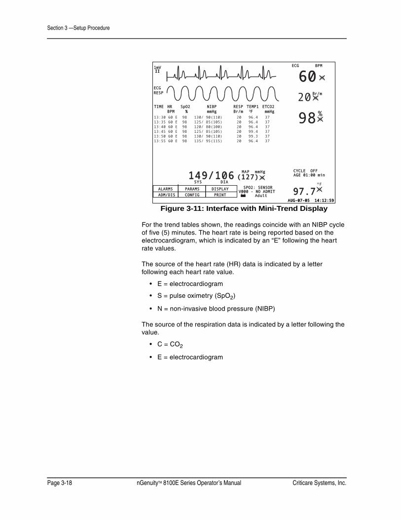
Section 3 —Setup Procedure
Page 3-18 nGenuityTM 8100E Series Operator’s Manual Criticare Systems, Inc.
Figure 3-11: Interface with Mini-Trend Display
For the trend tables shown, the readings coincide with an NIBP cycle of five (5) minutes. The heart rate is being reported based on the electrocardiogram, which is indicated by an “E” following the heart rate values.
The source of the heart rate (HR) data is indicated by a letter following each heart rate value.
• E = electrocardiogram
• S = pulse oximetry (SpO2)
• N = non-invasive blood pressure (NIBP)
The source of the respiration data is indicated by a letter following the value.
• C = CO2
• E = electrocardiogram
ALARMS PARAMS DISPLAYALARMS PARAMS DISPLAY
AdultAdultV000 - NO ADMITV000 - NO ADMITSPO2: SENSORSPO2: SENSOR
ADM/DIS CONFIG PRINTADM/DIS CONFIG PRINTAUG-07-05 14:12:59AUG-07-05 14:12:59
IIII
%
MAP mmHgMAP mmHg CYCLE OFFCYCLE OFF
1mV1mV BPMBPM
Br/mBr/m
6060
9898
97.797.7
2020
- +- +
149/106149/106 (127)(127) AGE 01:00 minAGE 01:00 min
Fo
ECGECGRESPRESP
ECGECG
SYS DIASYS DIA
TIME HR SpO2 NIBP RESP TEMP1 ETCO2TIME HR SpO2 NIBP RESP TEMP1 ETCO2 BPM % mmHg Br/m BPM % mmHg Br/m OF mmHgF mmHg13:30 60 E 98 130/ 90(110) 20 96.4 3713:35 60 E 98 125/ 85(105) 20 96.4 3713:40 60 E 98 120/ 80(100) 20 96.4 3713:45 60 E 98 125/ 85(105) 20 99.4 3713:50 60 E 98 130/ 90(110) 20 99.3 3713:55 60 E 98 135/ 95(115) 20 96.4 37

Criticare Systems, Inc. nGenuityTM 8100E Series Operator’s Manual Page 3-19
Section 3 —Setup Procedure
ADM/DIS Softkey (Admit/Discharge)
A patient is admitted or discharged in ADM/DIS window. It is necessary to correctly specify the Patient Size since this adjusts the monitoring defaults.
Figure 3-12: Admit/Discharge Window
NOTE: Patient Size can be also set in the ALARMS window. This is the same setting and can be changed in either location.
NOTE: The Unit Label is for identification purposes when using wireless or hardwire networks. Do not change the number unless otherwise instructed to by the manufacturer.
Adult/Pediatric/Neonatal(Patient Size)
The monitor is designed to look at the patient size information selected in the ADM/DIS window and determine whether the monitor should use the adult, pediatric, or neonatal alarm settings while monitoring.
The patient mode is determined by patient size and is displayed in the System Status Line, not with other patient data at the bottom of the display screen. The patient size/mode is shown as Adult, Pediatric or Neonate.
When the patient size is changed in the ADM/DIS window, the monitor determines which window appears when the ALARMS softkey is selected. By changing patient size, the user effectively changes all the alarm limits for all the monitoring modules; SpO2, ECG, NIBP, Temperature, and Respiration. The patient size setting also adjusts the maximum NIBP pressure limit. For Adult and Pediatric the limit is 300 mmHg. The limit for Neonate is 150 mmHg.
ALARMS PARAMS DISPLAY ADM/DIS CONFIG PRINT
Section 3 —Setup Procedure
Page 3-20 nGenuityTM 8100E Series Operator’s Manual Criticare Systems, Inc.
Admitting andDischarging Patients
• It is not necessary to admit a patient for the monitor to function properly. There is no audible alarm for the No Admit condition. A message appears in the informational message box to indicate that no patient is admitted.
• It is possible to admit a blank patient. If this is done, there is no patient data label on printed reports. Data from various patients could appear to merge together onto one trend table or graph.
• It is recommended that the admit and discharge feature be used between each patient so that there is a clear break between patient histories in the memory. This also ensures that label headers are properly printed out for each patient.
• The discharge feature returns the monitor to the user default profile last selected. If no user profiles have ever been selected on a new monitor the CUSTOM DEFAULTS found in the first position in the defaults window is used. This feature has been included to help prevent unusual monitoring settings from being carried forward accidentally to new patients.
• The patient must be admitted to properly use all the network communications features of the monitor.
Patient Information To enter, change, or update patient information:
1. Set the menu to ADM/DIS and press the knob.
2. Turn the knob to Update and set to YES. Press the knob. The patient data field can now be selected.
3. Go to Patient Size and check that it is correct. Change to Adult, Pediatric or Neonate as necessary.
4. Go to the patient name and identity fields. Turn the knob to select the desired field. Press the knob to go to the blank line. Turn the knob to select the correct letter.
NOTE: Letters and digits may be entered using the rotary knob. Two arrow characters also appear among the letters and digits. Selecting the back arrow allows corrections to be made. The down arrow skips directly to the next line when finished entering a line.
5. Fill in the remaining patient information blanks as desired. Enter a value for unit label only if using central station communication.
6. Select EXIT to return to the main screen. The patient data is updated on the main screen.
7. Exit the ADM/DIS window and re-enter before attempting to admit a patient.
NOTE: If menu text is entered and then the menu is not “touched” for 45 seconds, the monitor accepts the inputs and removes the menu.
CAUTION ! !

Criticare Systems, Inc. nGenuityTM 8100E Series Operator’s Manual Page 3-21
Section 3 —Setup Procedure
Procedure forAdmitting a Patient
To admit a patient, proceed as follows:
1. Set the menu to ADM/DIS and press the knob. the ADM/DIS window appears. If the patient data needs to be updated use the patient information procedure.
2. Rotate the knob to highlight Admit. The admit selection is not available if a patient is already admitted.
3. Press the knob to select Admit. Turn the knob to YES. The message NEW PATIEN is also entered into the trend memory.
NOTE: If there is no patient data this admits a blank patient.
4. Turn the knob back to EXIT to return to the main screen, or proceed to update patient information.
Procedure forDischarging a Patient
To discharge a patient, proceed as follows:
1. Set the menu to ADM/DIS and press the knob. the ADM/DIS window appears.
2. Rotate the knob to highlight Discharge. The discharge selection is not available if a patient has not been admitted.
3. Press the knob to select Discharge. Turn the knob to YES.
4. The monitor responds with a confirmation screen.
5. Turn the knob to YES and press to confirm.
6. The monitor clears the patient data fields and returns the monitor to the last user default profile that was selected.

Section 3 —Setup Procedure
Page 3-22 nGenuityTM 8100E Series Operator’s Manual Criticare Systems, Inc.
CONFIG Softkey (System Configuration)
This softkey allows access to the configuration settings. When activated a configuration settings window appears.
Figure 3-13: System Configuration Window
This window contains settings that are related to the general function of the overall monitor. The window also has some settings that may affect physiological monitoring.
Password Protection Several settings on the CONFIG screen are password protected. These are functions that generally should not be changed during use and their settings should be adjusted by biomedical technicians or supervisory personnel. These include; Alarm Tone Warning, Line Frequency, Enter Service Mode and Enter Simulation Mode. Contact your CSI dealer or the CSI Service Department for service passwords.
• The Alarm Tone Warning setting can permanently disable alarm functions. See “Alarms and Messages” in Section 5 for more information on Alarms.
• The Line Frequency setting affects the ECG and SpO2 filter function. See “INCORRECT LINE FREQUENCY SETTING” in this section.
• The Return to Factory Defaults setting may make changes affecting all of the physiological monitoring modules.
Service mode and Simulation Mode are described in the nGenuity 8100E Series Service Manual (CAT 1448).
ALARMS PARAMS DISPLAY ADM/DIS CONFIG PRINT
Date Format DD-MM-YYYYDate DAY 7 MONTH DEC YEAR 2006Time 17:47Freeze timeout 2 minutesAlarm tone warning ONLanguage ENGLISHLine Frequency 60Restore Factory Defaults NOEnter Service Mode NOEnter Simulation Mode NOPatient Size Adult
EXIT
CAUTION ! !

Criticare Systems, Inc. nGenuityTM 8100E Series Operator’s Manual Page 3-23
Section 3 —Setup Procedure
Time/Date Setting The time and date are set in the CONFIG softkey window. Time format dictates whether the date is shown in day-month-year (DD-MM-YYYY) or month-day-year (MM-DD-YYYY) format. Changing the time and date while monitoring a patient does not affect the accurate display of patient data, but it clears any trend data that has been recorded.
Freeze Waveforms The freeze function can be set to freeze the waveform frame from 30 seconds to five minutes. Choosing OFF causes the FREEZE key to hold the screen permanently until the FREEZE key is pressed again. The FREEZE key also captures waveforms that are obscured by dialog boxes and pop-up windows. When the FREEZE key is pressed the waveforms are redrawn on the screen. The freeze function forces an exit from the current pop-up window or dialog box.
Alarm Tone Warning The Alarm tone warning feature allows the user to permanently disable any and all audible alarms. This feature turns off the double beep when a new alarm comes in and alarms are silenced. This feature can only be accessed with a password.
NOTE: Set this safeguard according to your facility protocols and according to local safety regulations for medical devices.
Language Settings The following languages are available in the monitor: English, French, German, Italian, Spanish, Russian, and Portuguese.
To change the language:
1. Press the ON/OFF key to start the monitor. The key is located on the top right side of the monitor, the topmost key on the keypad.
2. Turn the menu knob until the CONFIG softkey is highlighted. The CONFIG softkey is located at the center bottom of the main menu.
3. Press the knob in to select the CONFIG softkey. The configuration window appears.
4. Locate the language setting which is the sixth item from the top. Turn the knob until the language setting is highlighted.
5. Press the knob to select the language setting. The current language shown to the right is highlighted.
6. Turn the knob until the desired language appears.
7. Press the knob again to select the new language.
8. EXIT the configuration window.

Section 3 —Setup Procedure
Page 3-24 nGenuityTM 8100E Series Operator’s Manual Criticare Systems, Inc.
The language should be properly set when saving user default profiles. The correct language can then be restored using only the DEFAULT key and the default profile dialog box when an unfamiliar language is set on the monitor.
In situations where the monitor has been left for over 24 hours without power or charged batteries, the language setting as well as other defaults may be lost. In this condition the monitor reverts to the language set in the last selected user default profile. English is the default language when no other has been selected.

Criticare Systems, Inc. nGenuityTM 8100E Series Operator’s Manual Page 3-25
Section 3 —Setup Procedure
Printer Settings The PRINT softkey allows access to the printer settings window.
Figure 3-14: Print Configuration Window
If the internal thermal printer does not respond, check Print Type to make sure that it is not set to OFF.
The settings Alarm Print causes the monitor to print all parameters upon the activation of a new high or medium level alarm.
See “Printing and Data Ports” in Section 7 for more information on printing.
Print Type TABULAR PRINTINGNumerical values for all current parameters are printed.
GRAPHICAL PRINTINGIf both waveform 1 and 2 have been set to a physical parameter the print out is a split dual waveform. If only one of the waveforms is turned on, a single waveform prints using the entire waveform area. If both waveforms are turned off, the waveform area of the print out is blank.
Serial Type Trend and demand printing to a serial printer can be done by setting Serial Type to Tabular. To print Alarm, BP or Interval data to a serial printer, Alarm Print, BP Print or Interval Print Type must be set to serial.
NOTE: Monitors with older software revisions may have a selection called Print Device in place of Serial Type. Print Device sets all printing to the internal printer or serial printer, or turns off the printing function.
ALARMS PARAMS DISPLAYADM/DIS CONFIG PRINT
EXIT
Print Type GraphicalAlarm Print OFFBP Print TabularInterval Print OFF Interval Print Type TabularSnapshot Size 6 secondsHistory Size 6 secondsWaveform 1 ECG II Gain x1.0Waveform 2 PLETH Gain x1.0Printer Speed 25.0 MM/SEC
Serial Type OFF
Serial Format CUSP Baudrate 38400

Section 3 —Setup Procedure
Page 3-26 nGenuityTM 8100E Series Operator’s Manual Criticare Systems, Inc.
Default Settings
Alarms Settings The monitor defaults to the Adult Factory Defaults.
Alarm Type Range Factory Defaults
Adult Pediatric NeonateAlarm Volume 1-10 5 5 5
ECG lead fail high, medium, low medium medium medium
Heart Rate High 80-250, Off 150 150 180Heart Rate Low 20-160, Off 40 40 90
SpO2 High 70-98, Off Off Off OffSpO2 Low 1-98, Off 90 90 90
NIBP Systolic High 75-240, Off 200 200 140NIBP Systolic Low 35-150, Off 50 50 50NIBP Diastolic High 50-180, Off 100 100 80NIBP Diastolic Low 15-50, Off 30 30 30NIBP Mean High 70-200, Off 150 150 100NIBP Mean Low 25-125, Off 50 50 40
Temperature High 68.0-111.0°F, Off 100.0°F 100.0°F 100.0°F20.0-44.0°C, Off 37.8°C 37.8°C 37.8°C
Temperature Low 68.0-111.0°F, Off 94.0°F 94.0°F 94.0°F20.0-44.0°C, Off 34.4°C 34.4 34.4
Respiration High 6-150, Off 35 36 60Respiration Low 0-150, Off Off Off OffCO2 Inspired High 0-100 mmHg, Off
0.0-12.5 %, Off0.0-12.5 kPa, Off0.0-94.0 Torr, Off
10 mmHg1.5 %
1.5 kPa10.0 Torr
10 mmHg1.5 %
1.5 kPa10.0 Torr
10 mmHg1.5 %
1.5 kPa10.0 Torr
CO2 Inspired Low 0-100 mmHg, Off0.0-12.5 %, Off0.0-12.5 kPa, Off0.0-94.0 Torr, Off
OffOffOffOff
OffOffOffOff
OffOffOffOff
CO2 Expired High 0-100 mmHg, Off0.0-12.5 %, Off0.0-12.5 kPa, Off0.0-94.0 Torr, Off
55 mmHg7.5 %
7.5 kPa56.0 Torr
55 mmHg7.5 %
7.5 kPa56.0 Torr
55 mmHg7.5 %
7.5 kPa56.0 Torr
CO2 Expired Low 0-100 mmHg, Off0.0-12.5 %, Off0.0-12.5 kPa, Off0.0-94.0 Torr, Off
5 mmHg1.0 %
1.0 kPa5.5 Torr
5 mmHg1.0 %
1.0 kPa5.5 Torr
5 mmHg1.0 %
1.0 kPa5.5 Torr

Criticare Systems, Inc. nGenuityTM 8100E Series Operator’s Manual Page 3-27
Section 3 —Setup Procedure
Monitoring Parameters
* ST selection present for all monitors but only functional if the monitor has the ST/Arrhythmia option.
Parameter Selectable Options Factory DefaultHR Source Smart, ECG, SpO2, NIBP Smart
Respiration On, Off On
ECG Cable 5 Lead, 3 Lead 5 LeadDetect Pacemaker On, Off OffECG Filter Diagnostic, Monitor, ST* MonitorSensitivity Low, Medium, High Medium
Temperature On, Off OnTemperature Unit °F, °C °F
SpO2 Average 3, 6, 9,12,15,18, 21 12SpO2 Search Time 10, 20, 30, 40 20
CO2 Units Percent, mmHg, kPa, Torr mmHgN2O Compensation On, Off Off
NIBP Tone End, None None
Heart Rate Tone Volume 1-10, Off 5

Section 3 —Setup Procedure
Page 3-28 nGenuityTM 8100E Series Operator’s Manual Criticare Systems, Inc.
Display Settings
Setting Selectable Options Factory DefaultWaveform 1:
Type: Lead I, Lead II, Lead III, Lead V, Lead avL, Lead avR, Lead avF, and Off
ECG II
Gain: 0.5x, 1x, 2x, or 4x 1xSweep: 6.25, 12.5, 25, or 50 mm per second 25 mm per second
Size: 25 or 50 mm 25 mmWaveform 2:
Type: Lead I, Lead II, Lead III, Lead V, Lead avL, Lead avR, Lead avF, Resp, Pleth, Cascade, BxB, ET CO2, and Off
Cascade
Gain: 0.5x, 1x, 2x, or 4x 1xSweep: 6.25, 12.5, 25, or 50 mm per second 25 mm per second
Size: 25 or 50 mm 25 mmWaveform 3:
Type: Lead I, Lead II, Lead III, Lead V, Lead avL, Lead avR, Lead avF, Resp, Pleth, Cascade, MINI-TREND, BxB, ET CO2, and Off
Cascade
Gain: 0.5x, 1x, 2x, or 4x 1xSweep: 6.25, 12.5, 25, or 50 mm per second 25 mm per second
Size: 25 mm 25 mmWaveform 4:
Type: Lead I, Lead II, Lead III, Lead V, Lead avL, Lead avR, Lead avF, Resp, Pleth, Cascade, MINI-TREND, BxB, ET CO2, and Off
PLETH
Gain: 0.5x, 1x, 2x, or 4x 1xSweep: 6.25, 12.5, 25, or 50 mm per second 25 mm per second
Size: 12 or 25 mm 25 mmWaveform 5:
Type: Lead I, Lead II, Lead III, Lead V, Lead avL, Lead avR, Lead avF, Resp, Pleth, Cascade, BxB, ET CO2 and Off
Off
Gain: 0.5x, 1x, 2x, or 4x 1xSweep: 6.25, 12.5, 25, or 50 mm per second 25 mm per second
Size: 12 or 25 mm 12 mmWaveform 6:
Type: Lead I, Lead II, Lead III, Lead V, Lead avL, Lead avR, Lead avF, Resp, Pleth, Cascade, BxB, ET CO2, and Off
Off
Gain: 0.5x, 1x, 2x, or 4x 1xSweep: 6.25, 12.5, 25, or 50 mm per second 25 mm per second
Size: 12 mm 12 mm
External Display On, Off Off

Criticare Systems, Inc. nGenuityTM 8100E Series Operator’s Manual Page 3-29
Section 3 —Setup Procedure
Configuration Settings
Printer Settings
* 1-20 seconds only available if Internal Print Type is set to Serial.
Configuration Selectable Options Factory DefaultDate format MM-DD-YYYY, DD-MM-YYYY MM-DD-YYYYDate Day, Month, Year Not ApplicableTime Hour, Minute Not Applicable
Freeze Timeout 30 seconds, 1, 2, 3, 4, 5 minutes, Off 2 minAlarm Tone Warning On, Off On
Language English, French, German, Italian, Spanish, Russian, Portuguese
English
Line Frequency 50, 60 Hz By Destination
Restore Factory Defaults
Yes, No No
Enter Service Mode Yes, No NoEnter Simulation Mode
Yes, No No
Patient Size Adult, Pediatric, Neonate Adult
Setting Selectable Options Factory DefaultPrint Type (Demand) Graphical, Tabular, Off Graphical
Alarm Print Off, Graphical, Tabular, Serial OffBP Print Off, Graphical, Tabular, Serial Off
Interval Print Off, 1s, 2s, 5s, 10s, 15s, 20s, 30s, 1, 2, 5, 10,15, 30, 60 minutes, 2, 4, 8, 12, 24 hours*
Off
Interval Print Type Graphical, Tabular, Serial TabularSnapshot Size 6,12,18, 24 seconds 6 secondsHistory Size 6,12 seconds 6 seconds
Waveform 1 ECG I, II, III, V, aVR, aVL, aVF, Resp, PLETH, ET CO2, Off
ECG II
Gain (waveform 1) x0.5, x1.0, x2.0, x4.0 x1.0Waveform 2 ECG I, II, III, V, aVR, aVL, aVF, Resp,
PLETH, ET CO2, OffPLETH
Gain (waveform 1) x0.5, x1.0, x2.0, x4.0 x1.0
Printer Speed 12.5, 25.0, 50.0 mm/sec 25.0 mm/secSerial Type Off, Tabular TabularSerial Format TEXT, CSV, CUSP CUSPBaud Rate 2400, 4800, 9600, 19200, 38400, 57600,
HI-SPEED38400


Criticare Systems, Inc. nGenuityTM 8100E Series Operator’s Manual Page 4-1
Section 4 — Patient Monitoring
Introduction to Clinical Use
This section provides instructions for patient connections and monitoring. The caregiver is expected to be fully familiar with patient monitoring techniques and with the functions of this monitor before using it with a patient.
Before you Begin Protect yourself and your patient. Read the precautions for each measured parameter that appears in this section.
These instructions describe use of the basic sampling devices and accessories that come with your monitor. An extended list of approved accessories can be found in “Accessories” in Appendix A.
The monitor should always be checked by the caregiver before use for actual patient monitoring. Perform the following procedure before using the monitor with each patient.
1. Make sure that monitor has been fully charged before use. Check that the AC power cord is plugged in for long-term monitoring situations.
2. Check the menus and default settings to confirm that the monitor is setup correctly.
3. Examine the accessories for wear, damage or contamination. Replace or disinfect the accessories as required.
4. Turn the desired monitoring modules to ON in the PARAMS softkey window.
5. Select the correct mode of operation (Adult/Pediatric/Neonate) by entering the patient size in the ALARMS, ADM/DIS or CONFIG softkey windows.
• All accessories connected to the patient monitor, must comply with all applicable UL (Underwriters Laboratories) standards and IEC standards for such products.
• Substitution of recommended sensor and sampling accessories may cause inaccurate measurements and degrade patient safety, or may damage the monitor.
CAUTION ! !

Section 4 —Patient Monitoring
Page 4-2 nGenuityTM 8100E Series Operator’s Manual Criticare Systems, Inc.
SpO2 Monitoring (Pulse Oximetry)
The following instructions describe procedures for preparing a patient for SpO2 monitoring.
Shown below is the patient monitor with a pulse-oximetry finger sensor attached. This adult finger sensor (CAT 934SDN) is one of many sensor styles available. Use the SpO2 sensors only as directed.
The monitor’s SpO2 connection accepts any DOX™ compatible SpO2 sensor using the DB-9 connector.
Figure 4-1: Sensor Connection for SpO2

Criticare Systems, Inc. nGenuityTM 8100E Series Operator’s Manual Page 4-3
Section 4 —Patient Monitoring
• The sensors and sensor extension cables are intended to be used only with the monitors specified for those sensors. The user must verify the compatibility of the monitor, sensor, and cable prior to use, otherwise patient injury may result.
• If the SpO2 reading drops to 83%, check the cable connections for proper connections and the SpO2 accessories for damage.
• The pulse oximeter sensor may cause skin irritation and pressure necrosis. Inspect the pulse oximeter sensor site every two to four hours or per hospital protocol. Move the sensor to a different location if skin irritation is present.
• Excessive amounts of motion at the sensor sites may cause errors in reading. Attempt a reading when motion has stopped, or move the sensor to another site.
• Ensure the sensors used are the sensors specified for the monitor. See “Sensor Selection” in this section for approved sensors.
• Initial SpO2 readings on a patient in the range of 81-84% are related to an input signal which is equivalent in the Red and Infrared AC low-level monitoring channels. This type of signal may be indicative of a high ambient noise environment or a short circuit fault in the sensor wiring. Verify monitoring system on a healthy individual (user) and/or verify the patient's plethysmographic waveform quality prior to clinical evaluation.
WARNING ! !
CAUTION ! !
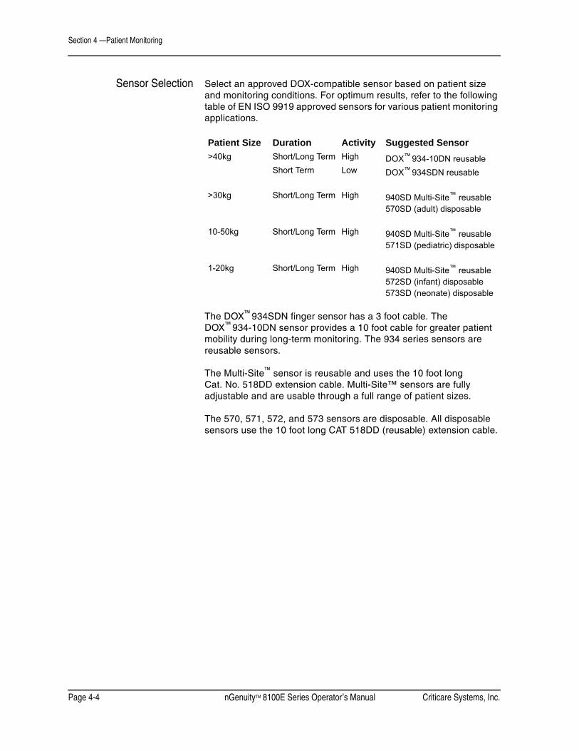
Section 4 —Patient Monitoring
Page 4-4 nGenuityTM 8100E Series Operator’s Manual Criticare Systems, Inc.
Sensor Selection Select an approved DOX-compatible sensor based on patient size and monitoring conditions. For optimum results, refer to the following table of EN ISO 9919 approved sensors for various patient monitoring applications.
The DOX™ 934SDN finger sensor has a 3 foot cable. The DOX™ 934-10DN sensor provides a 10 foot cable for greater patient mobility during long-term monitoring. The 934 series sensors are reusable sensors.
The Multi-Site™ sensor is reusable and uses the 10 foot long Cat. No. 518DD extension cable. Multi-Site™ sensors are fully adjustable and are usable through a full range of patient sizes.
The 570, 571, 572, and 573 sensors are disposable. All disposable sensors use the 10 foot long CAT 518DD (reusable) extension cable.
Patient Size Duration Activity Suggested Sensor>40kg Short/Long Term High DOX™ 934-10DN reusable
Short Term Low DOX™ 934SDN reusable
>30kg Short/Long Term High 940SD Multi-Site™ reusable570SD (adult) disposable
10-50kg Short/Long Term High 940SD Multi-Site™ reusable571SD (pediatric) disposable
1-20kg Short/Long Term High 940SD Multi-Site™ reusable572SD (infant) disposable573SD (neonate) disposable

Criticare Systems, Inc. nGenuityTM 8100E Series Operator’s Manual Page 4-5
Section 4 —Patient Monitoring
SpO2 Sensor Placement Apply the sensor with the LED lights positioned on the nail side of the finger and the detector on the fleshy portion of the finger.
Do not tape over the pulse oximeter sensor housing. Taping over the housing may cause injury and sensor failure due to excessive pressure. If the sensor needs to be secured, place tape over the cable, immediately behind the sensor.
Figure 4-2: Finger Sensor Placement
The sensor must be properly positioned for a plethysmographic waveform to appear. Placing tape too tightly around an extremity reduces blood flow, thus diminishing the amplitude of the plethysmographic waveform.
If possible, do not place the pulse oximeter sensor on the same extremity as the blood pressure cuff or an arterial line. Place the pulse oximeter sensor on the side of the patient opposite the blood pressure cuff or an arterial line. The occlusion of the blood flow during blood pressure determinations could affect saturation readings.
The pulse oximeter sensor is light sensitive. Too much ambient light makes it difficult for the system to provide accurate readings. The system provides a high ambient light alarm message when it is necessary to shield the sensor from extraneous light sources such as phototherapy light or infrared heating lamps.
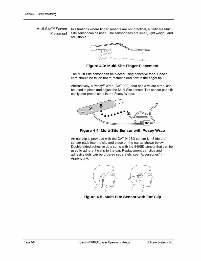
Section 4 —Patient Monitoring
Page 4-6 nGenuityTM 8100E Series Operator’s Manual Criticare Systems, Inc.
Multi-Site™ SensorPlacement
In situations where finger sensors are not practical, a Criticare Multi-Site sensor can be used. The sensor pads are small, light weight, and adjustable.
Figure 4-3: Multi-Site Finger Placement
The Multi-Site sensor can be placed using adhesive tape. Special care should be taken not to restrict blood flow in the finger tip.
Alternatively, a Posey® Wrap (CAT 920), that has a velcro strap, can be used to place and adjust the Multi-Site sensor. The sensor pads fit easily into precut slots in the Posey Wraps.
Figure 4-4: Multi-Site Sensor with Posey Wrap
An ear clip is provided with the CAT 940SD sensor kit. Slide the sensor pads into the clip and place on the ear as shown below. Double-sided adhesive dots come with the 940SD sensor that can be used to adhere the clip to the ear. Replacement ear clips and adhesive dots can be ordered separately, see “Accessories” in Appendix A.
Figure 4-5: Multi-Site Sensor with Ear Clip

Criticare Systems, Inc. nGenuityTM 8100E Series Operator’s Manual Page 4-7
Section 4 —Patient Monitoring
The Multi-Site sensor can also be placed on the forehead. A forehead applicator and velcro head band are provided with the CAT 940 sensor kit. Place the Multi-Site sensor pads into the forehead applicator.
The forehead applicator can be fastened with an adhesive strip or a head band can be used.
Figure 4-6: Sensor Forehead Application
The Multi-Site sensor can be used for measuring SpO2 on an infant foot. Place the light emitting sensor pad on the top of the infant foot. The detector should be placed on the bottom. Adhesive tape may be used to hold the sensor pads in place.
Figure 4-7: Sensor Foot Placement
Using SpO2 Sensors Pulse oximeter sensors should be replaced if they fail or become excessively worn. Replacement sensors may be ordered from Criticare Systems, Inc. See “Accessories” in Appendix A.
Disposable sensors are for single patient use only and should be used with highly infectious patients. Reusable sensors should be disinfected between uses with each new patient.
Do not stretch sensor cables. Store cables carefully after forming them into loose loops. If cables are stretched, electrical failures could result.
The sensors must not be tightly wound around fingers or other objects. The cable used in DOX™ reusable sensors has a minimum acceptable bend radius of 0.75 inches (19mm). For short term storage, the sensor should be loosely looped or hung on a large diameter hook.

Section 4 —Patient Monitoring
Page 4-8 nGenuityTM 8100E Series Operator’s Manual Criticare Systems, Inc.
ECG Monitoring (Electrocardiogram)
The following instructions describe procedures for preparing a patient for ECG monitoring.
Shown below is the patient monitor with an ECG cable attached. This cable (CAT 1075/S) is one of several ECG accessories available. A list of approved ECG accessories is listed in “Accessories” in Appendix A.
Figure 4-8: ECG Cable Connection
• This device is not intended for intracardiac ECG applications. Use the ECG monitor and accessories only as directed.
• Do not place defibrillator paddles on or next to ECG patient electrodes. Contact between defibrillator paddles and ECG electrodes could injure the patient.
• The conductive parts of the lead electrodes including the neutral electrode, should not come in contact with other conductive parts including an earth ground. Such contact could result in patient injury or death or equipment damage.
• ECG electrodes can cause skin irritation. Change the electrodes and reposition every 24 hours or sooner if there is sign of inflammation.
WARNING ! !
CAUTION ! !

Criticare Systems, Inc. nGenuityTM 8100E Series Operator’s Manual Page 4-9
Section 4 —Patient Monitoring
Pacemakers andElectronic Devices
The monitor is designed to recognize pacer signals and reject them as invalid portions of the ECG waveform. The pacer signals are displayed to the user as white vertical bars (spikes) on the waveform.
The ECG monitor and accessories are protected against the effect of electrosurgery and high frequency equipment. The ECG monitor has also been designed to be protected against the effects of cardiac defibrillator discharge.
Tall T-Wave Performance The nGenuity 8100E Series monitor properly counts normal rhythms with T-Wave heights to 120% of the QRS height at a heart rate of 80 BPM.
• The presence of tall T-waves greater than 120% (80% when the Arrhythmia option is ON) of the R-wave may result in a double-counting of beats.
Narrow Beat Rejection The nGenuity monitor does not reject narrow beats as defined in EC-13 either with or without the Arrhythmia option turned on.
Electrode Selection Proper ECG electrode size is determined by patient’s body size. Criticare recommends using adult 527 series patient ECG electrodes with snap style connections. If adult electrodes overlap, use smaller electrodes.
Pediatric/neonate electrodes CAT 1094 will fit ECG cable Cat. No. 1095. Special attention should be taken to position electrodes so that the leads do not constrict around the infant’s neck and limbs.
The caregiver may use third party electrodes with the monitor. The substitute electrodes must comply with UL and IEC standards for such products. The monitor is designed for use with silver/silver chloride (Ag/AgCl) electrodes. Use of stainless steel electrodes is not recommended and will impair ECG performance.
ECG cables for either snap or pinch style electrode connections are available. See “Accessories” in Appendix A for the complete list.
WARNING ! !

Section 4 —Patient Monitoring
Page 4-10 nGenuityTM 8100E Series Operator’s Manual Criticare Systems, Inc.
Lead Placement The monitor provides ECG options for 3- and 5-lead patient setups. The following instructions describe both the 3- and 5-lead configurations. For the correct electrical resistance and shielding, it is important to use the recommended ECG cables for this monitor.
3-Lead Setup The three major planes that detect electrical activity are Lead I, Lead II, and Lead III, known as the standard or conventional bipolar limb leads. Lead II (RA and LL), commonly known as the standard lead configuration, is often used for monitoring because its waveform characteristics are typically most prominent. For general monitoring purposes, Leads I and II are most commonly used.
• Lead I produces good P waves, reflecting atrial activity.
• Lead II produces good QRS complexes, reflecting ventricular activity.
Place the electrodes on the patient in the standard lead configuration. Leads I, II, III may be selected in the monitor’s DISPLAY window.
Figure 4-9: Electrode Locations for 3-Lead Setup
LA
LL
RA
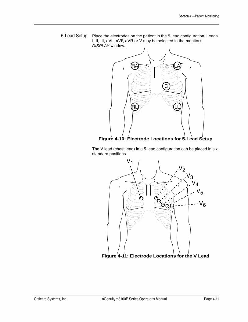
Criticare Systems, Inc. nGenuityTM 8100E Series Operator’s Manual Page 4-11
Section 4 —Patient Monitoring
5-Lead Setup Place the electrodes on the patient in the 5-lead configuration. Leads I, II, III, aVL, aVF, aVR or V may be selected in the monitor’s DISPLAY window.
Figure 4-10: Electrode Locations for 5-Lead Setup
The V lead (chest lead) in a 5-lead configuration can be placed in six standard positions.
Figure 4-11: Electrode Locations for the V Lead
RA
RL LL
C
LA
V1V2
V3V4
V5
V6

Section 4 —Patient Monitoring
Page 4-12 nGenuityTM 8100E Series Operator’s Manual Criticare Systems, Inc.
Electrode Application Proper skin preparation is essential for ECG monitoring. Before applying the electrodes, remove natural skin oils by abrading the site with an alcohol pad. Dry the area with gauze or a towel.
If the electrodes do not adhere well, apply benzoin to the area before applying the electrodes. Benzoin helps prevent skin breakdown and enhances electrode adhesion.
1. Check the cables for fraying or other deterioration.
2. Attach the ECG cable to the monitor.
3. Attach the electrodes to the ECG cable.
4. Start the monitor and confirm that it is functioning properly. Set the monitor to display an ECG waveform. Check the settings for Pacer Detect and ECG Filter in the PARAMS menu.
5. Using the PARAMS menu, select the desired lead configuration. (3 or 5 leadwire)
6. Using the DISPLAY menu select the desired lead view. (I,II,III, aVL, aVF, aVR, or V)
7. Prepare and clean the patient application site as necessary. Place the electrodes on the patient.
8. Lower the ECG sensitivity if the signal amplitude is too high.
9. Set the ECG display gain option so that the waveform is clearly displayed on the monitor’s display screen.
10.Remove the electrodes once every 24 hours and examine the skin for irritation and breakdown. Apply clean electrodes to a different spot. Check the lead wires and cables periodically for frays and cracks.
If there is excessive patient motion, the leads may be taped to the patient. Do not tape directly over the electrodes. Secure the leads with adhesive tape about two centimeters from the application site as shown below.
Figure 4-12: Securing an ECG Electrode

Criticare Systems, Inc. nGenuityTM 8100E Series Operator’s Manual Page 4-13
Section 4 —Patient Monitoring
ECG Auto Lead Switching
If a 5-lead cable is being used, the monitor has the ability to display alternate leads in cases of fault in the selected lead. If a 3-lead cable is used, failure of any lead results in no other usable leads, so no “lead switching” is possible. However, the monitor does display which lead or electrode has failed.
Since the 5-lead switching system uses a right-leg drive, failure of the RL lead results in no leads being available. The monitor identifies the RL as having failed with the message ECG LEADS OFF.
Lead failure assumes that signal has been lost from an electrode that is required for the desired lead view. Loss of signal from unnecessary electrodes does not cause lead switching.
Primary Lead The monitor identifies a primary lead that is used to report heart rate numerical data. If no leads are being displayed, the primary lead defaults to lead II. If ECG waveforms are being displayed, the monitor selects the waveform closest to the top of the screen as the primary lead. Lead switching only occurs in the primary lead view.
Lead failure during monitoring causes one of the following results:
1. If failure occurs in the primary lead, while currently being displayed, the system attempts to switch from the current lead view to an alternate lead view.
The system switches to a valid (non-failed) lead view, if a valid lead exists. The failed electrode is indicated by an alarm message. The slot label of the primary lead visibly changes to the new lead view. The alternate waveform is drawn in the slot.
2. If the failure occurs for Lead II, while no ECG leads are displayed, the primary lead is changed to an alternate lead. The smart heart rate is determined from the new lead view. No lead switching is apparent from the main screen.
3. If no alternate is available for a primary lead, an ECG: LEADS OFF alarm is generated. The smart heart rate defaults to the next available source, indicated by a change of the heart rate numerical display. No lead switching occurs.
4. If required electrodes for a displayed non-primary lead are not available, an error message displays. The waveform becomes a straight line. No lead switching occurs.
When the lead fail condition is corrected, the system reverts back to the original lead that was displayed before the fail condition occurred.

Section 4 —Patient Monitoring
Page 4-14 nGenuityTM 8100E Series Operator’s Manual Criticare Systems, Inc.
Alternate Lead Priority The ECG monitor automatically determines lead switching as shown in the following table.
In cases indicated by a dash, no switching occurs, since the electrode is unused for that selected lead. In cases where the RL fails, no switching occurs because that electrode is required for each selectable lead configuration.
Since the augmented leads, aVR, aVL or aVF, are calculated or derived from the actual limb leads, failure of any lead except V causes failure of all the derived leads.
Primary Lead Switches to alternate on failureLL LA RA V
Lead I - II III -Lead II I - III -Lead III I II - -Lead V I II III IILead aVR,aVL,aVF I II III -

Criticare Systems, Inc. nGenuityTM 8100E Series Operator’s Manual Page 4-15
Section 4 —Patient Monitoring
NIBP Monitoring (Non-invasive Blood Pressure)
The following instructions describe procedures for preparing a patient for monitoring using the ComfortCuff™ NIBP module.
Shown below is the patient monitor with an adult size arm blood pressure cuff and a four (4) foot hose. This adult arm cuff (CAT 475) is one of many blood pressure cuffs available. Use the NIBP accessories only as directed.
The monitor’s NIBP connection accepts any Criticare NIBP cuff using a quick-connect style fitting.
Figure 4-13: NIBP Cuff Connection

Section 4 —Patient Monitoring
Page 4-16 nGenuityTM 8100E Series Operator’s Manual Criticare Systems, Inc.
• Check the patient frequently to ensure the NIBP cuff is not causing prolonged impairment of the patient's circulation.
• The accuracy of noninvasive blood pressure readings may be adversely affected by the presence of drugs or therapies which alter the patient's cardiovascular dynamics.
• The sensitivity of blood pressure measurement may be affected when monitoring patients with intra-aortic balloon pumps.
Selecting Cuffs and Hoses This monitor works with Criticare blood pressure cuffs and hoses only. Using the monitor with other brands of cuffs may cause inaccurate measurements.
Proper cuff size and placement is essential to assure accurate blood pressure measurement. The recommended cuff width-to-length ratio is about 2:1, so that if the cuff width is 40% of arm circumference, the cuff bladder length encircles 80% of the arm. A cuff that is too narrow results in falsely high pressure readings. A cuff that is too wide results in falsely low pressure readings.
The cuff shown below on the left is too small for the arm, therefore, full cuff pressure is never applied to the artery. This causes an erroneously high blood pressure reading. The cuff shown on the right is of adequate width for the arm, and full cuff pressure is applied to the brachial artery.
Figure 4-14: Blood Pressure Cuff Size
WARNING ! !
CAUTION ! !

Criticare Systems, Inc. nGenuityTM 8100E Series Operator’s Manual Page 4-17
Section 4 —Patient Monitoring
Cuffs for thighs are available for large patients or those where neither arm is available for cuff placement. Blood pressure measured at the thigh is typically 20-30 mmHg higher (when the patient is standing, not prone) than blood pressure measured at the upper arm.
Placing the NIBP Cuff Wrap the cuff snugly around the extremity, leaving enough room between the cuff and the extremity for two fingers. If the cuff is too loose, it cannot be inflated properly and may cause errors in measured BP values.
• It is best to wrap a bare extremity; putting the cuff over clothing may cause errors in measured values.
• Care should be taken to center the dot on the cuff directly over the brachial artery. (Shown below as a circle with a vertical line.)
• The hose should not be twisted or kinked.
The end of the cuff (marked by an index line) should fall inside the range marked clearly on the inside of the cuff. If not, use a different size cuff.
Figure 4-15: Blood Pressure Cuff Size Range
Procedure 1. Check the System Status Line for the correct mode. The status line indicates Adult, Pediatric or Neonate.
2. Select a cuff as described previously in this section.
3. Connect the BP cuff to the monitor.
4. Secure the cuff around the patient's extremity.
5. Make sure there are no kinks or other obstructions in the hose extending from the cuff.
6. Press the NIBP key on the front keypad of the monitor.
Place this side against the skin
Este lado hacia la piel
Ce côte en contact avec la peau

Section 4 —Patient Monitoring
Page 4-18 nGenuityTM 8100E Series Operator’s Manual Criticare Systems, Inc.
Pressing the NIBP key causes the monitor to take one measurement. The monitor may make a second attempt if there is excessive motion during the first attempt to take a measurement.
Press and hold the NIBP CYCLE/STAT key to begin taking Stat NIBP measurements. NIBP measurements are then taken repetitively for 5 minutes. The numerical parameters on the display are updated with each measurement.
If an NIBP cycle time has been selected the monitor automatically takes NIBP measurements at scheduled intervals. Press the NIBP key to begin measuring at automatic intervals.
Taking NIBPMeasurements
For optimum accuracy, the patient should keep the cuffed part of the arm at the same level as the heart. NIBP measurement points above the level of the heart gives reduced pressure values. Measurement points below the heart level gives increased values. These errors are due to the weight of the blood.
Figure 4-16: Arm Position for NIBP Measurement
An average measurement on a non-moving patient takes less than 40 seconds. At the end of each measurement, the cuff automatically deflates. The monitor automatically attempts a second measurement (with no displayed error message) if it cannot calculate a blood pressure on the first inflation.
If a patient experiences a sudden dramatic drop in blood pressure, the system may not measure the blood pressure on the first attempt. The system automatically attempts another pressure measurement, and detects the change on the second attempt.
Do not compress the cuff or the cuff hose externally. Compression of the cuff or the cuff hose causes measurement error. For optimum accuracy, the patient should remain still during blood pressure measurement. Excessive patient motion may adversely affect any oscillometric NIBP device.
Heart

Criticare Systems, Inc. nGenuityTM 8100E Series Operator’s Manual Page 4-19
Section 4 —Patient Monitoring
Gas Monitoring The following instructions describe procedures for preparing a patient for CO2 monitoring.
Sampling CircuitConnections
The monitor uses a sidestream gas sampling circuit composed of a water trap, a sampling line and a sampling device. The water trap is a combination filter and moister condenser.
Shown below is the patient monitor with water trap (CAT 938F-N) and sample line (CAT 625N). The monitor’s gas sampling receptacle fits WaterChek™ series water traps.
Figure 4-17: Gas Sampling Connection

Section 4 —Patient Monitoring
Page 4-20 nGenuityTM 8100E Series Operator’s Manual Criticare Systems, Inc.
The monitor’s gas sampling connection (from the water trap) accepts gas sampling lines using the Luer style connections. It is important to use the recommended water trap and sample line combinations in order to provide the correct flow rates for monitoring purposes.
• Never attach intravenous tubes to gas sampling connections. Gas sampling lines may be inadvertently connected to intravascular fluid systems; allowing air into a blood vessel.
• Change sample lines and sampling devices between each patient. Infectious agents may be transmitted through reuse of sampling lines.
• Do not connect the monitor’s exhaust for return flow to the breathing circuit. Infectious agents may be transmitted through reverse flow from sampling devices.
• Use of longer sampling lines or extensions decreases the monitor’s response time and can affect accuracy.
• Leakage or internal venting of sampled gases may cause inaccurate gas readings. Please contact technical services to resolve these issues.
NOTE: The water trap is for single use only. Do not attempt to drain and reuse the water trap.
WARNING ! !
CAUTION ! !

Criticare Systems, Inc. nGenuityTM 8100E Series Operator’s Manual Page 4-21
Section 4 —Patient Monitoring
Water Trap The water trap has a connection located at the top that fits up and into the gas receptacle of the monitor.
Figure 4-18: WaterChek™ 2+ Water Trap
The trap slides out of the front receptacle and can be quickly replaced if it becomes filled or occluded as shown below. The front of the WaterChek™ 2+ (Cat. No. 938F-N) has a female Luer-lock sampling line entrance.
Sampling Devices Shown below is the monitor with a patient gas sampling device (nasal cannula) and an 8-foot sampling line attached. This nasal cannula (CAT 624) is used for CO2 monitoring.
Figure 4-19: Nasal Cannula
If using the nasal cannula, position it directly under the patient’s nose with the prongs inserted into the nostrils. Slide the adjuster forward to close the loop around the head.
The nasal cannula is intended for single patient use only. Alternate sampling devices such as masks may be used if they have a female Luer-lock sampling entrance. Intubation breathing circuits require a sampling entrance near the connection to the endotracheal tube.
Luer-lockentrance
Slide up andinto receptacle

Section 4 —Patient Monitoring
Page 4-22 nGenuityTM 8100E Series Operator’s Manual Criticare Systems, Inc.
Intubated Patients The monitor can be used with intubated patients. Recommended water traps and breath circuit adapters should be used. The trap reservoirs should be checked regularly. The breath circuit should be checked regularly for leaks or disconnections. Follow the directions provided with your endotracheal tube for additional precautions.
The following ventilation circuit adapters are available from Criticare. Alternate ventilation circuit adapters may be used if they have a female Luer-locking sampling entrance.
Figure 4-20: Adapters with Luer-lock Entrance
The ventilation circuit adapters shown above are for single patient use only and are intended to be disposed after. The adapters have a 15mm outside dimension to one connection end and a combination 15mm inside dimension with a 22mm outside dimension on the other end.
• Additional adapters between the endotracheal tube and the sampling entrance should not exceed five (5) centimeters.
Standard breath circuit configurations are shown below beginning with a common endotracheal tube with a 15mm outside diameter. The circuit then extends to meet a standard 22mm inside diameter ventilation flex tube. Confirm the proper fit of all breath circuit components before attempting patient monitoring.
Cat. No. 616 Cat. No. 617
CAUTION ! !

Criticare Systems, Inc. nGenuityTM 8100E Series Operator’s Manual Page 4-23
Section 4 —Patient Monitoring
Figure 4-21: Straight Ventilation Adapter Setup
Figure 4-22: Elbow Ventilation Adapter Setup
Calibration and Startup The monitor automatically begins an auto-calibration sequence when powered up. During this time the monitor may display a flat capnogram. When the calibration and warm up sequence is over the system message disappear and normal operation begins.
22mm I.D. Ventilation Tube �with 15mm I.D. Adaptor
Sampling Line (Luer-lock)
15mm I.D./15mm O.D.Ventilation Adaptor with �Luer-lock Sampling Entrance
EndotrachealTube 15mm O.D.
22mm I.D. Ventilation Tube �with 15mm I.D. Adaptor
Sampling Line �(Luer-lock)
15mm I.D./15mm O.D.Elbow Adaptor with �Luer-lock Sampling Entrance
Endotracheal Tube 15mm O.D.

Section 4 —Patient Monitoring
Page 4-24 nGenuityTM 8100E Series Operator’s Manual Criticare Systems, Inc.
Procedure for GasMonitoring
1. Check the settings of N2O Compensation in the PARAMS window.
2. Slide the WaterChek™ trap into the monitor’s gas receptacle.
3. Attach a scavenging line to the rear exhaust port, if anesthetic agents are being used. A waste gas recovery system should be used.
4. Attach a sample line to the Luer fixture located on the front of the WaterChek™ trap.
5. Make sure there are no kinks or other obstructions in the line extending from the trap.
6. Attach a patient sampling device to the sampling line. Use either a nasal cannula, mask or ventilation tube adapter.
7. Replace sampling devices, lines and water traps if they become blocked or filled.
Occlusions The monitor displays a visual message CO2: OCCLUSION if the gas sampling system is blocked. If the sampling line or water trap becomes partially blocked, the item should be replaced.
Anesthetic GasExhaust Recovery
Always use an exhaust gas recovery system when using anesthetic gases. Scavenging kit Cat. No. 655 can be used to connect the monitor to a gas scavenging system.
1. Slide the tube over the nozzle of the exhaust port located on the side of the monitor.
2. Connect female Luer-lock end to an exhaust recovery system.
A straight adapter 19mm O.D./19mm I.D. with male Luer-lock entrance is provided with the scavenging kit to provide a connection to scavenging tubing.
The monitor displays CO2: CHECK LINE if the scavenging line is blocked.

Criticare Systems, Inc. nGenuityTM 8100E Series Operator’s Manual Page 4-25
Section 4 —Patient Monitoring
CO2 Monitoring Allow the CO2 monitor to warm up and auto-calibrate before use. It is necessary to have the water trap sampling line attached so that the monitor draws the correct air flow.
When a patient is connected, the monitor begins displaying the end-tidal and inspired CO2 values in the parameter box. The capnogram, waveform, if selected as a displayed waveform provides a graphic representation of the patient’s respiration cycle.
The source of the numerical respiration rate may be determined from the capnogram or from the ECG data. See “Respiration Smart Source” in Section 3 for a description of the smart respiration function.
USE OF NITROUS OXIDESince nitrous oxide has a similar infrared signature to that of CO2, and it affects absorption of CO2, special care must be taken when measuring CO2 while anesthetics are being used. The monitor provides a manually activated compensation for nitrous oxide between 40% and 80% when the compensation option is selected in the PARAMS window.
INTERFERING GASES FOR CO2The monitor reports small changes in CO2 when anesthetic agents are used. Expected CO2 changes are provided here for the purposes of comparison.
For Gas mixtures of 5% CO2
Agent Agent Volume* Change of CO2
N2O
HalothaneEnfluraneIsofluraneSevofluraneDesfluraneXenonHeliumEthanolIsopropanolAcetoneMethanePropellant
60%
4%5%5%5%
15%80%50%
1%1%1%5%1%
+0.1% with N2O compensation ON+1.0% with N2O compensation OFF+0.3%+0.3%+0.3%+0.2%+1.1%Not intended for use with Xenon–0.3%–0.1%–0.1%
0%0%0%
* Gas mixtures balanced with nitrogen.

Section 4 —Patient Monitoring
Page 4-26 nGenuityTM 8100E Series Operator’s Manual Criticare Systems, Inc.
Temperature Monitoring
The following instructions describe procedures for preparing a patient for temperature monitoring.
Shown below is the patient monitor with a skin surface temperature probe. This reusable surface probe (CAT 422) is one of many temperature probes available. Use the temperature accessories only as directed.
The monitor’s temperature connection accepts any Criticare YSI-400 style or YSI-700 style temperature accessory.
Figure 4-23: Temperature Probe Connection

Criticare Systems, Inc. nGenuityTM 8100E Series Operator’s Manual Page 4-27
Section 4 —Patient Monitoring
• Skin abrasion and tissue burn hazard. Separate the monitor and temperature cables from electrocautery systems; keep both active and ground electrodes of the electrocautery system in close proximity so that the temperature sensor is outside the radio-frequency current field.
• The esophageal/rectal sensors are not recommended for use with neonates and small infants undergoing tracheostomy or internal jugular artery catheterization and laser surgical procedures.
• Possible airway obstruction hazard with esophageal sensors when accompanied by tracheal or bronchial intubation.
Using TemperatureAccessories
Skin surface temperature monitoring is intended for the detection of hypothermic and hyperthermic conditions. The skin temperature sensor is designed for placement on the surface of the skin only. This sensor consists of a thermistor affixed to an adhesive layer of material covered by a metallic film. The sensor design provides accurate measurement of surface body temperature (See Sensor Package insert for detailed information).
To insure the proper performance of the temperature accessories, follow the precautions listed below.
• Forced mating of the connectors without proper alignment may cause damage to the connectors and interruption in electrical continuity.
• Pulling the cable cord may cause interruption in electrical continuity. Grasp cable at its connectors to disconnect the cable from instrument or disposable probe connectors.
• During use, do not entwine the cable with other electrical cables.
WARNING ! !

Section 4 —Patient Monitoring
Page 4-28 nGenuityTM 8100E Series Operator’s Manual Criticare Systems, Inc.
Directions for Use withSkin Surface Probe
1. Check the monitor settings for correct setup.
2. Insert the cable's instrument-side connector into the monitor's input jack.
3. Prepare skin site according to established protocol. (Suggest same skin preparation as for ECG electrodes). Adhere sensor to skin site.
4. Unwind the cable from the protective card and peel the sensor from the card.
5. Align the cable's sensor-side connector with the sensor's connector and push firmly to assure full contact.
6. Verify proper operation of monitor.
7. Disconnect sensor connector from cable connector when temperature monitoring is discontinued.
Directions for Use withEsophageal/Rectal Probe
The disposable esophageal/rectal temperature probe is a sensitive and accurate temperature transducer, to be used clinically where continuous temperature monitoring is required. See the esophageal/rectal temperature probe insert for detailed probe description.
1. If a patient has to be intubated with an endotracheal tube, perform the intubation prior to placing the temperature probe into the esophagus.
2. Lubricate the temperature probe prior to insertion and place the probe in accordance with currently acceptable medical procedures.
3. Verify the position of the probe by acceptable medical procedures.
4. Align the sensor's connector with the monitor cable's connector and push firmly to assure full contact. Forced mating of the connectors without proper alignment may cause damage to the connectors and interruption in electrical continuity.
Cleaning To clean the temperature cables and sensors, see “Temperature Cable” in Section 8.

Criticare Systems, Inc. nGenuityTM 8100E Series Operator’s Manual Page 5-1
Section 5 — Alarms and Messages
Alarm Description The monitor provides both audible and visible alarm indicators to alert the operator of system status changes and physiological parameter alarms.
Alarms are provided for all monitored parameters. Each parameter limit alarm condition triggers both audible and visible alarms until one of the following events occurs:
• The parameter value returns to within the alarm limit.
• The alarm limit is set beyond the present parameter value.
• The SILENCE key is pressed. (Audible alarms only)
• The monitor is placed in Standby Mode. (Audible alarms only)
Audible Alarms All alarms conform to EN 475 requirements. Informational messages and a system alerts do not have an audible alarm component.
HIGH PRIORITY ALARMSThe high priority alarm consists of a pair of bursts. Each burst consists of five tone pulses. The pair of bursts repeat every eight seconds. For each burst there is a short delay between the 3rd and 4th pulse. The frequency of each pulse is 1000 Hz.
MEDIUM PRIORITY ALARMSEach burst consists of 3 pulses. The frequency is 800 Hz and the repeat cycle is approximately 25 seconds.
LOW PRIORITY ALARMSEach burst consists of two pulses. The frequency is 350 Hz and the repeat cycle is 15 seconds.
ADVISORY ALERTSEach burst consists of two pulses. The frequency is 300 Hz and the repeat cycle is approximately five minutes.

Section 5 —Alarms and Messages
Page 5-2 nGenuityTM 8100E Series Operator’s Manual Criticare Systems, Inc.
Visible Alarms The monitor provides visible text alarms on the interface display screen.
FLASHING NUMERICAL PARAMETERSIf a physiological parameters exceeds a high limit or falls below a low limit value the numerical value displayed flashes. This function cannot be suspended and is visible when pop-up menus are activated.
ALARM MESSAGE LINESThere is space for two text lines provided directly below the NIBP parameter box. If multiple alarms are active, they alternate in the alarm area. The bottom line is used for the informational messages and advisory alerts.
Low level alarms and informational level messages are displayed in this area for the vital signs that have a waveform displayed. For parameters that do not have a waveforms displayed, all level of alarms are reported in the Alarm Message Lines.
The informational, low, and medium level alarm text messages are colored yellow and the high alarm warning messages are red.
WAVEFORM SLOT VISUAL ALARMSWhen a high or medium alarm occurs for a vital sign that has an active waveform, the message is displayed in the top center of the waveform in large text. If there are multiple alerts to be displayed in a waveform slot, the messages alternate.
If the waveform exists in multiple slots, either through cascade or duplicate waveforms from alternate leads, the waveform messages only occur in the top most slot.
Waveform Slot Alarms are not visible during the following conditions.
• The waveform is not selected to be displayed.
• A pop-up window or menu covers the waveform slot.
If a high or medium level alarm message cannot be displayed in the waveform slot due to a pop-up window, the alarm message is displayed in the Alarm Message Lines near the bottom of the screen.
Waveforms Frozen Alarm text messages that appear in the waveform slot are not frozen. The high and medium alarm messages appear based on the current waveform data not the frozen waveform shown.
%9494AdultAdult
V000 - NO ADMITV000 - NO ADMITSPO2: SENSORSPO2: SENSOR
- +- +
IIII
x1x1
1mV1mV HIGH PULSE RATE

Criticare Systems, Inc. nGenuityTM 8100E Series Operator’s Manual Page 5-3
Section 5 —Alarms and Messages
Alert Icons There are two alert icons that may appear on the main screen.
SUSPENDED ALARM ICONSA red bell icon with a “X” indicates that an alarm limit has been turned to OFF when the icon occurs in the Numerical Parameter Boxes.
When the red bell icon appears in the top waveform slot, all the monitor’s audible alarms have been silenced. The duration of the silence condition appears to the right of the bell icon.
2 min = 2 minutes = permanent
Visual alarms continue to be displayed as described.
BATTERY ICONSA battery icon appears in the System Status Line indicating that a battery is present when AC power is not available. The battery icon changes color depending on the charge status. See “Battery Indicators” in Section 3 for more information about battery status and charging.
Special Alarm Conditions
The monitor’s alarms may be adjusted to suit the specific needs of the clinical environment. Special functions are included for the benefit of the user, so that “nuisance alarms” during patient setup do not become distracting to the caregiver. Alarm Silence and Standby Mode are available for this purpose. There are additional safeguards included to protect against the misuse of these functions.
Alarms at Start Up Audible alarms do not occur until the first valid measurement has occurred for that parameter. Visual messages and alarms are present immediately when a module is activated. The alarms and start sequence can be altered by the presence of an external monitoring module. See the instructions provided with the external module.
Alarm Silence An alarm SILENCE key is provided on the front panel of the monitor.
SILENCE 2 MINUTESPressing the SILENCE key momentarily begins a 2 minute alarm silence. The alarm icon appears in the System status Line followed by the phrase 2 min in white text.
New high and medium level alarms end the 2 minute silence when the alarm condition occurs.
Pressing the SILENCE key a second time ends the silence condition and normal alarms resume.
∞
- +

Section 5 —Alarms and Messages
Page 5-4 nGenuityTM 8100E Series Operator’s Manual Criticare Systems, Inc.
PERMANENT SILENCEPress and hold the SILENCE key to permanently silence the alarms. The alarm icon appears in the System Status Line followed by an infinity symbol. Notice that the long key-press tone occurs after holding the key in for two seconds, confirming that permanent silence was selected.
• Note that future alarms are also silenced and do not end the silence condition. This includes the silence of alarms at a higher level than the original condition.
Pressing the SILENCE key a second time ends the silence condition and normal alarms resume.
Audible Alarms Disabled(Warning Tone)
During a permanent alarm silence condition, and when this safeguard is activated, an Audible Alarms Disabled (Warning Tone) occurs when a new high or medium level alarm is generated. The tone is a low pitched double beep the same as the long key press tone.
The Audible Alarms Disabled function (Alarm tone warning) can be set in the CONFIG menu. A password is required to turn this function off.
Alarm Volume The alarm volume can be set to levels 1 to 10 with 10 being the loudest. This can be set in the ALARMS menu.
The alarm volume cannot be set to OFF. To permanently silence the monitor press and hold the SILENCE key.
NOTE: This function does not change the volume of the audible heart rate. The pulse tone volume is adjusted separately in the PARAMS menu (Heart Rate Tone Vol).
Minimum VolumeAuto-Reset
If the alarm volume is set to 1, the monitor automatically returns to the value 2 each time the monitor is turned on. If the monitor was turned off with a value setting greater than one, that value returns when the monitor is powered up again. This function cannot be disabled.
Standby Mode The message ALARM/CO2 appears in large red characters when the Standby Mode is active. When in Standby Mode, all alarms are silenced and the CO2 pump stops but remains on for zero calibration.
The function is turned on and off by pressing the STAND BY key.
CAUTION ! !
Criticare Systems, Inc. nGenuityTM 8100E Series Operator’s Manual Page 5-5
Section 5 —Alarms and Messages
SpO2 Low LimitAuto-Reset
If the SpO2 alarm limit level is set below 85%, the monitor automatically returns to the value 85% each time the monitor is turned on. If the CUSTOM DEFAULTS are set with an SpO2 low limit value above 85%, the monitor automatically returns to the higher value each time the monitor is turned on. This function cannot be disabled.
SpO2 Low LimitOff Alarm
There is an alarm message generated if the SpO2 Low Limit is set to OFF. The message LOW SAT OFF appears in yellow text in the Alarm Message Lines. The monitor also displays the alarm bell icon in the lower right corner of the SpO2 numerical display box. The bell icon is normally displayed when any SpO2 limit is turned off.
Alarms Testing To check and ensure that the audible and visual alarm limit settings are operating as expected, the user may do so by performing the following suggested procedure at least once a year:
1. Apply power to the monitor. Observe that all displays and LEDs illuminate.
2. Place the SpO2 probe on your finger. Allow readings to stabilize.
3. Observe the pulse rate that is being displayed and adjust the low pulse rate limit to a value greater than the observed pulse rate value.
4. Verify that the low pulse rate violation message is displayed on the LCD message bar and that the alarm tone sounds.
5. Once verified, return the low pulse rate or SpO2 waveform limit to the previously set value, or to one that is required for the patient to be monitored.

Section 5 —Alarms and Messages
Page 5-6 nGenuityTM 8100E Series Operator’s Manual Criticare Systems, Inc.
Alarm Message List Included here is a list of messages, alerts, and alarms that may appear in the waveform slots or in the system message lines of the display.
Shared Source Alarms Alarms and messages for heart rate may be generated by the ECG, SpO2, or the NIBP module.
Priority DescriptionLOW PULSE RATE High The heart rate value has dropped below the value set
in the ALARMS menu.
HIGH PULSE RATE High The heart rate value has exceeded the value set in the ALARMS menu.
ECG AlarmsPriority Description
ECG:LOST High The ECG signal is too low in amplitude. Check electrodes, lead wires, and cables. If necessary, change to a different lead.
ECG:RA LEAD OFF High/Med/Low The right arm lead is off. Reconnect the lead.
ECG:LA LEAD OFF High/Med/Low The left arm lead is off. Reconnect the lead.
ECG:LL LEAD OFF High/Med/Low The left leg lead is off. Reconnect the lead.
ECG: V LEAD OFF High/Med/Low The chest lead is off. Reconnect the lead.
ECG:LEADS OFF High/Med/Low The ECG leads are off. Either the right leg is off or there is more than one lead off. Check the lead(s).
Respiration AlarmsPriority Description
LOW RESP Medium The respiration value has dropped below the value set in the ALARMS menu. This can be generated from the CO2 or the ECG module.
HIGH RESP Medium The respiration value has exceeded the value set in the ALARMS menu. This can be generated from the CO2 or ECG module.
RESP: LOST Medium Unable to determine a respiration from the impedance (ECG) respiration data.
ESU-RESP OFF Medium The unit detects electro-surgical interference and suspends monitoring of the waveform and numerical values to avoid inaccurate physiological readings.
RESP:IMPED HIGH Low Generated by the ECG module. Poor contact at the electrodes or defective ECG cables.
RESP:ERROR Low Cannot determine a respiration rate from the ECG sampling module data.

Criticare Systems, Inc. nGenuityTM 8100E Series Operator’s Manual Page 5-7
Section 5 —Alarms and Messages
SpO2 AlarmsPriority Description
LOW SpO2 High/Medium The SpO2 value has dropped below the value set in the ALARMS menu.
HIGH SpO2 Medium The SpO2 value has exceeded the value set in the ALARMS menu.
SpO2:LOST Medium The monitor is receiving no SpO2 signal. Check sensor site for low perfusion and reposition sensor if necessary.
SpO2:SENSOR Low The SpO2 sensor is not properly positioned.
SpO2:HI AMBIENT Low The SpO2 module is reading excessive light. Shield the sensor or reduce the amount of ambient light.
SpO2: SIGNAL Low The SpO2 signal is too weak to measure. Check sensor site for low perfusion and reposition sensor if necessary.
SpO2:NO SENSOR Low The SpO2 sensor is missing or defective. Connect or replace the sensor.
SpO2: ERROR Low The monitor has detected a fault with the SpO2 function. Contact the CSI Service Department.
SpO2: SEARCH Informational The module cannot find a pulse in SpO2 signal.
LOW SAT OFF Informational The SpO2 low limit has been set to OFF in the ALARMS menu.
Temperature AlarmsPriority Description
LOW TEMP Medium The temperature value has dropped below the value set in the ALARMS menu.
HIGH TEMP Medium The temperature value has exceeded the value set in the ALARMS menu.
TEMP:NO PROBE Low Temperature probe is not connected. Temperature reading is not valid.
TEMP:BAD PROBE Low Temperature probe is defective.
TEMP:INVALID Low Temperature reading is out of range. Check probe position.
TEMP:CALIB ERR Low Temperature module is out of calibration. Contact the CSI Service Department.
TEMP:ERROR Informational The monitor has detected a fault with the temperature module. Contact the CSI Service Department.

Section 5 —Alarms and Messages
Page 5-8 nGenuityTM 8100E Series Operator’s Manual Criticare Systems, Inc.
NIBP AlarmsPriority Description
BP: LOW SYS Medium The systolic value has dropped below the value set in the ALARMS menu.
BP: HIGH SYS Medium The systolic value has exceeded the value set in the ALARMS menu.
BP: LOW DIA Medium The diastolic value has dropped below the value set in the ALARMS menu.
BP: HIGH DIA Medium The diastolic value has exceeded the value set in the ALARMS menu.
BP: LOW MAP Medium The mean arterial pressure value has dropped below the value set in the ALARMS menu.
BP: HIGH MAP Medium The mean arterial pressure value has exceeded the value set in the ALARMS menu.
BP: CHECK CUFF Low Displayed when a neonatal cuff is used while the monitor is in the adult or pediatric mode. Switch to neonatal mode when using a neonatal cuff. Can also indicate a leak in the cuff, or the cuff is wrapped too loosely.
BP: ERROR Low The monitor has detected a fault with the NIBP function. Contact CSI Service Department.
BP: LO PULSE AMP Low Pulse amplitude is too low. Reposition cuff.
BP: MAX PRESSURE Low Maximum allowed cuff pressure (300 mmHg adult or 150 mmHg neonatal) has been attained.
BP: MAX TIME Low Maximum time (2 minutes) allowed for measuring the blood pressure has been exceeded. Repeat measurement.
BP: NO DEFLATE Low The monitor was unable to deflate the NIBP cuff. Disconnect the cuff and contact the CSI Service Department.
BP: NOT TAKEN Low The monitor was unable to take a blood pressure reading. Check cuff position.
BP: CALIB ERROR Low The monitor had detected a fault with the calibration. Cycle the power to the monitor. If the problem persists, contact the CSI Service Department.
BP: PLEASE WAIT Informational The cuff has not completely deflated. Wait for deflation and then press the NIBP key again.

Criticare Systems, Inc. nGenuityTM 8100E Series Operator’s Manual Page 5-9
Section 5 —Alarms and Messages
Gas AlarmsPriority Description
APNEA High No breath detected. Check patient for apnea. Check sampling device and adjust placement if necessary. May indicate a leak in the breathing circuit.
CO2: CHECK LINE Medium Sample line is not connected. Connect sampling line.
Scavenging line blocked or defective scavenging system. Remove occlusion or correct system.
CO2: OCCLUSION Medium The sampling line or trap is completely blocked. Replace sampling accessories as needed.
CO2: INSERT TRAP Low Trap not inserted. Trap is partially blocked, wrong type of trap, or defective. Replace trap.
CO2: ZEROCAL Low The monitor is calibrating the gas module to current ambient conditions. Monitoring is suspended.
CO2: FCAL ERROR Low The monitor has detected a fault with the gas calibration table. Contact CSI Service Department.
CO2: UCAL ERROR Low The monitor has detected a fault with the user calibration. Perform a user calibration. Contact the CSI Service Department if the problem continues.
CO2: ERROR Low Invalid factory calibration. Contact CSI Service Department.
CO2: BENCH FAIL Low The monitor has detected a fault with the gas bench. Contact CSI Service Department.

Section 5 —Alarms and Messages
Page 5-10 nGenuityTM 8100E Series Operator’s Manual Criticare Systems, Inc.
System AlertsPriority Description
LOW BATTERY Advisory Battery power is low. Recharge batteries.
NO ADMIT Informational The patient has not been admitted in the ADM/DIS menu.
WAVEFORM FROZEN Informational The user has selected the waveforms to be frozen. Press the FREEZE key again to resume normal display.
PRINT: PAPER OUT Informational The printer has detected the end of the paper roll.
PRINT: HEAD UP Informational Paper is loaded and manual lever is up. Move the lever to the down position. Check for paper jam.
PRINT: Vp ERROR Informational Internal printer communication problem. Contact CSI Service.
PRINT: TEMP ERR Informational The thermal printing element is not the correct temperature. Contact CSI Technical Service.
V000 - NO ADMIT Informational The patient has not been admitted and wireless communication is not setup. The numbers following the “V” indicate the unit’s wireless network indentifier.

Criticare Systems, Inc. nGenuityTM 8100E Series Operator’s Manual Page 6-1
Section 6 — Trends
Description The trend memory stores patient data at regular intervals for review at a later time. Trend data can be reviewed by printing it out on the monitor's built-in printer or an external serial printer.
To view the tabular trend, press the TREND key and the table appears in the lower channels of the waveform display.
Trend Interval The trend interval can be changed by pressing and holding the TREND key while viewing the tabular trend. A second window appears. Change the trend to the desired interval by rotating the knob.
Trend data for each parameter is stored as follows:
• SpO2 value is stored every 30 seconds at the zero and 30 seconds mark.
• The precedent heart rate and precedent respiration are stored every 30 seconds at the zero and 30 seconds mark. The secondary sources are recorded if the primary data is unavailable.
• NIBP storage is determined by cycle time interval, demand and stat readings. Every NIBP reading is stored in the trend memory.
• Continuous temperature readings are stored every 30 seconds at the zero and 30 seconds mark.
• Inspired and expired CO2 data is stored every 30 seconds at the zero and 30 seconds mark.
Capacity The trend memory can store up to 24 hours of trend data at 30 second intervals, including NIBP at three minute intervals.
When the trend memory is filled to maximum capacity, the new trend data begins to overwrite the oldest trend data in the memory.
Trend Screen Update The table is not updated while it is being viewed. Scroll up to view data that is recorded after the trend screen is activated. The trend screen automatically returns to the main screen after 45 seconds.

Section 6 —Trends
Page 6-2 nGenuityTM 8100E Series Operator’s Manual Criticare Systems, Inc.
Trend Setup The trends may be viewed in graphical format in the trend window. Up to two parameters may be viewed in graphical format.
The trend view may be changed in the Trend Setup window.
To view trends:
1. Press the TREND key to enter the trend window.
2. Either the Tabular or Graphics trend appears.
3. Press the and hold the TREND key to enter the trend settings.
4. Set the trend type to Graphical or Tabular.
5. If Graphical is selected, set the Trend Interval and Trend Parameters as desired.
6. EXIT the trend setting window. The trend displays.
7. Rotate the knob clockwise to see older data.
8. Press the TREND key to exit trends.
Selecting EXIT returns to the main screen. Press the TREND key again to return the trend display after changing the settings.
NOTE: The trend setting window defaults to Tabular Trend. The Settings for Trend Interval, First Trend Parameter and Second Trend Parameter are not visible until the Trend Type is set to Graphical.

Criticare Systems, Inc. nGenuityTM 8100E Series Operator’s Manual Page 6-3
Section 6 —Trends
If Graphical is selected, set the Trend Interval and Trend Parameters as desired.
Figure 6-1: Graphical Trend Setup Window
If Tabular is selected, the Trend Screen is set to Basic Trend Display. Select YES or NO for Use parameter colors.
Figure 6-2: Tabular Trend Setup Window
EXIT
Trend Type GraphicalTrend Interval 4 HoursFirst Trend Parameter HR Color ¤Second Trend Parameter SPO2 Color ¤
Clear Trends NO
EXIT
Trend Type TabularTrend Interval 30 seconds
Use Parameter Colors NO
Clear Trends NO

Section 6 —Trends
Page 6-4 nGenuityTM 8100E Series Operator’s Manual Criticare Systems, Inc.
Graphical Trends The graphical trend window covers the lower five waveform slots. The physiological parameter and the unit of measurement is listed vertically on the left side for the first displayed line graph. The second line graph is labeled vertically on the right side.
The graphical trend window displays for about 45 seconds before timing out. The trend window does not update automatically. The trend window updates each time it is accessed.
The most current data is always displayed on the right side. Time stamps for the selected Trend Interval are indicated below the line graphs.
Scrolling the Graph The trend window can be set to display up to 24 hours of data. Rotating the knob clockwise scrolls the graph to show older data. Rotating the knob counter-clockwise scrolls back towards the most current data.
The rate of advance varies with the selected Trend Interval.
Trend Interval Minutes per each click 2 hours 14 hours 28 hours 4
12 hours 624 hours 12
The time stamps are updated each time the knob is rotated. It is not possible to scroll past the current time.
The trend graph resets to the current time stamp upon exiting to the main screen and returning to the trend window. The trend graph remains at the selected time location while entering and returning from the trend settings window.
Interruption Due toPower Cycling
The graphical trend has gaps due to power cycling of the monitor. If the period of missing data is within the last 24 hour period the gaps appear where the power was turned off. These gaps are defined with gray backgrounds.
If the power was turned off for a period of more than a day, a blank period is inserted between the new and old data. The new data begins on a new window with new time stamps. The gap between the monitoring sessions is equal to the Trend Interval in length.

Criticare Systems, Inc. nGenuityTM 8100E Series Operator’s Manual Page 6-5
Section 6 —Trends
Graphical Trend Screen Two physiological parameters may be displayed at the same time in the graphical trend window. For NIBP the pressure values for diastolic, systolic, and mean are represented. The line graphs are color corresponding to the numerical display, as selected in the Graphical Trend menu. For parameters such as heart rate and respiration the color of the line graph changes to the color of the source data.
Figure 6-3: Graphical Trend Screen
ALARMS PARAMS DISPLAYALARMS PARAMS DISPLAYADM/DIS CONFIG PRINT ADM/DIS CONFIG PRINT
BP: PLEASE WAITBP: PLEASE WAIT
14:12:5914:12:59
IIII
ºCºC
%
MAP mmHgMAP mmHgCYCLE OFFCYCLE OFF
Br/mBr/m
1mV1mV BPMBPM
6060
979797
37.137.1
2020
ECG:LEADS OFFECG:LEADS OFF
147/89147/89(107)(107)- +- +
John SmitJohn Smith
100100
10:1210:12 JUN-18-05JUN-18-05 10:1210:12JUN-18-05JUN-18-05
0 0
5050150150
300300
22:1222:12
NIBPNIBP
mmHgmmHgBPMBPM
HRHR
AdultAdult
AGE 24;18 minAGE 24;18 min

Section 6 —Trends
Page 6-6 nGenuityTM 8100E Series Operator’s Manual Criticare Systems, Inc.
Tabular Trends
Heart Rate SourceIndication
The source of the heart rate data is indicated by a letter following each heart rate value. E = electrocardiogram, S = pulse oximetry, and N = Non-invasive blood pressure.
Respiration SourceIndication
The source of the respiration data is indicated by a letter following each value. E = electrocardiogram and C = CO2.
Tabular Trend Markers Various messages appear in the tabular trend to indicate that system events have occurred. A complete list is as follows:
FREEZE ON FREEZE OFFAUDIO ON AUDIO OFFSIM ON POWERNEW PATIEN
NOTE: Permanent silence and 2 minute silence are both recorded as an AUDIO ON/OFF event in the tabular trend table.
Trend Messages The trend also records messages in the trend table that indicate the status of the monitor at that time. The time and date stamp are also recorded when one of the following messages is recorded. All messages appear in the trend table regardless of the interval selected for the table or the time that the message occurred.
• When the monitor enters and exits Silence Mode the message AUDIO ON or AUDIO OFF is recorded in the trend table. This includes 2 minute silence and permanent silence conditions.
• When the monitor’s waveforms are frozen and unfrozen the message FREEZE ON or FREEZE OFF is recorded in the trend table.
• When the monitor is turned off and on the message POWER is recorded in the trend table.
• When a new patient is admitted in the ADM/DIS window, the message NEW PATIEN is recorded into the trend table. Note that Adult, Ped, or Neo is entered if/when age changes.
• When a patient is discharged in the ADM/DIS window, the message NEW PATIEN is recorded into the trend table.
At midnight the monitor records the date change into the trend table. This does not occur if the monitor was turned off at midnight.

Criticare Systems, Inc. nGenuityTM 8100E Series Operator’s Manual Page 6-7
Section 6 —Trends
Data Format The parameters are listed in the first column followed by the units.
• Time stamps at the half minute mark are displayed with a plus “+” sign.
• Measured parameters that exceed or drop below alarm limits are highlighted.
• When a sampling module is on and no value can be determined for the parameter, three dashes “---” are displayed in the trend table.
• If a sampling module is turned off in the PARAMS window, the word OFF displays in the trend.
• If there is no NIBP data for a particular time stamp, the NIBP trend area is left blank.
_______________________________________________________27-JAN-05 11:45+ 11:45 11:44+ 11:44 11:43+ 11:43
RATE BPM 60E 60E 60E 60ESpO2 % 99 99 99 98 NEW POWERNIBP SYS mmHg 135 PATIEN
DIA mmHg 95MAP mmHg 115
TEMP °F 98.6 98.6 98.6 OFFRESP Br/m 20 20 20 20CO2 INS kPa 0.0 0.0 0.0 0.0
EXP 0.0 0.0 0.0 0.0
_______________________________________________________Figure 6-4: Trend Display Table
NOTE: Monitors without CO2 monitoring will not show CO2 data.
For the trend table shown the interval is set to 30 seconds. The heart rate is being reported based on the electrocardiogram, which is indicated by the “E” following the heart rate values.
The source of the heart rate data is indicated by a letter following each heart rate value:
• E = electrocardiogram,• S = pulse oximetry,• N = non-invasive blood pressure

Section 6 —Trends
Page 6-8 nGenuityTM 8100E Series Operator’s Manual Criticare Systems, Inc.
NIBP View Monitors with software version 1.2F and newer, have a tabular trend view titled NIBP. When NIBP is selected, the trend report will only show trend records that contain blood pressure measurement.
To activate
1. Press the TREND key to show the trend display.
2. Press and hold the TREND key to access the trend settings.
3. Select Trend Interval and choose NIBP to activate this display option.
Clearing the Memory To clear the trend memory:
1. Press the TREND key to display the trend.
2. Press and hold the TREND key again to display the Trend Setup window.
3. Select the Clear Trends option and select YES to confirm the clearing of the trend data.
The trend memory is automatically cleared when:
• The Time and/or Date are changed in the menu
• Defaults reset.

Criticare Systems, Inc. nGenuityTM 8100E Series Operator’s Manual Page 7-1
Section 7 — Printing and Data Ports
Description The monitor is optionally equipped with a thermal dot-matrix printer which is located on the top of the rear of the unit. The nGenuity 8100E Series monitor is capable of printing all vital signs parameters in tabular (text). The monitor can also produce graphical (waveforms) formats as specified by the user.
Snapshot Size The period of time (in a graphical print) that starts 4.5 seconds prior to pressing the print key and lasting the duration of the "Snapshot" setting in the print menu. (i.e. if the print type is set to graphical and snapshot is set to 6 seconds then the 8100E Series monitor prints out the waveform data selected 4.5 seconds prior to a print keypress and 1.5 seconds after the print keypress).
History Size History size is a period of time defined by the user that is prior to the snapshot time period. History size can be selected as 6 or 12 seconds.
Print Modes
Demand Print If the print type is set to Tabular, pressing the PRINT key causes an immediate print-out of the vital signs numbers, date, time and patient data in a "tabular" text format.
If the print type is set to Graphical, pressing the PRINT key causes an immediate print-out of the selected waveforms for a duration as selected by "snapshot size."
Continuous Print If print type is set to Graphical, pressing and holding the PRINT key for two seconds causes the selected waveforms to print out continuously (until the PRINT key is pressed again) at 12.5mm/sec or 25mm/sec. If set to 50mm/sec, it defaults to 25mm/sec.
Alarm Print The monitor issues a printout if a high or medium alarm occurs, as selected by the user in the PRINT softkey window.
If the print type is set to Tabular, a “tabular demand print format” is issued if an alarm setting is violated.
If the print type is set to Graphical and snapshot size is set to 6 seconds, a 6 second graphical print strip is issued displaying the waveforms selected in the PRINT menu if an alarm setting is violated. This strip represents the history size added to the snapshot data.

Section 7 —Printing and Data Ports
Page 7-2 nGenuityTM 8100E Series Operator’s Manual Criticare Systems, Inc.
BP Print The monitor issues a printout at the completion of a successful non-invasive blood pressure reading, as selected by the user in the PRINT menu.
If print type is set to Tabular, a tabular demand print format is issued at the end of a successful non-invasive blood pressure reading. If print type is set to Graphical and snapshot size is set to 6 seconds a 6 second graphical print strip is issued displaying the waveforms selected in the PRINT menu at the completion of a successful non-invasive blood pressure reading.
Interval Print Interval prints are periodic automatic printouts as selected by the user in the PRINT menu. They are graphical, tabular or serial as selected in the PRINT window.
Freeze Print A freeze print is initiated by depressing the PRINT key after setting the monitor in "Freeze" mode (pressing the FREEZE key). The printout is determined by the settings in the PRINT menu. This strip represents the history size added to the snapshot data.
If print type is set to Graphical, the waveforms selected are printed out. The data printed is for a history time period followed by a snapshot time period.
If print type is set to Tabular, a demand tabular print is issued using the "frozen" numeric vital signs data on the screen.
Trend Print After displaying a trend on the 8100E Series' screen (by pressing the TREND key), pressing the PRINT key causes a trend print of the data displayed on the screen.
Pressing and holding the PRINT key (while a trend is displayed on the monitor's screen) causes all of the stored Trend data to print out.
The monitor must be set to internal printer for trend printing. The trend data is not sent to the serial port.

Criticare Systems, Inc. nGenuityTM 8100E Series Operator’s Manual Page 7-3
Section 7 —Printing and Data Ports
Print Formats The internal thermal dot-matrix printer is capable of printing vital signs parameters in tabular (text) or graphical (waveforms). Select the printout format in the PRINT softkey menu.
Tabular Printing A header is printed containing the monitor model, the operating software revision, the time and date, and the patient information. The title for each parameter follows.
Numerical values for all current parameters are printed. The sample below shows a tabular print out.
Figure 7-1: Tabular Printout
NOTE: Monitors without CO2 monitoring will not print out CO2 data.
CSI 8100E Series Rev 1.112-14-06 4:38:10NAME: SMITH JOHNID: 12345678Room number 100
12-14-06 04:38:10HR ( ECG ) 60 BPMSpO2 98 %RESP ( ECG ) 20 Br/mTEMP 96.4 FNIBP(04:30:22) 135 / 95 (115) mmHg GAS EXP INS CO2 5.0 3.0 kPa
12-14-06 04:38:16HR ( ECG ) 60 BPMSpO2 98 %RESP ( ECG ) 20 Br/mTEMP 96.4 FNIBP(04:30:22) 135 / 95 (115) mmHg GAS EXP INS CO2 5.0 3.0 kPa
12-14-06 04:38:22HR ( ECG ) 60 BPMSpO2 98 %RESP ( ECG ) 20 Br/mTEMP 96.4 FNIBP(04:30:22) 135 / 95 (115) mmHg GAS EXP INS CO2 5.0 3.0 kPa

Section 7 —Printing and Data Ports
Page 7-4 nGenuityTM 8100E Series Operator’s Manual Criticare Systems, Inc.
Graphical Printing If both waveform 1 and 2 have been set to a physical parameter the print out is a split dual waveform. If only one of the waveforms is turned on, a single waveform is printed using the entire waveform area. If both waveforms are turned off, the waveform area of the print out is blank. Selectable options for waveforms are ECG I, II, III, V, aVR, aVL, aVF, PLETH, ET CO2 and OFF. Numerical values for heart rate, SpO2, NIBP, temperature, and respiration are printed below the waveform grid.
Figure 7-2: Dual Waveform Printout
Figure 7-3: Single Waveform Printout
The printout can be configured with a variety of waveform pairs. The example in “Figure 7-2: Dual Waveform Printout” above shows an ECG and an SpO2 waveform. The top waveform information appear in the upper right corner of the printout. The lower waveform information appears directly below the waveform in the right corner.
The examples above are the shortest printed waveform views available. Longer printouts can be configured in the print menu.
Dat
a in
cor
ner
for t
opw
avef
orm
Dat
a in
cor
ner
for b
otto
m
wav
efor
m}
}
Dat
a in
cor
ner f
or
sing
le w
avef
orm
Indicates second waveform is off
}

Criticare Systems, Inc. nGenuityTM 8100E Series Operator’s Manual Page 7-5
Section 7 —Printing and Data Ports
Mini-Trend Printing The monitor can print out the Mini-Trend display. To print a Mini-Trend report:
1. Press and hold the PRINT key with Mini-Trends displayed.
2. The Mini-Trends print out in a strip from the serial printer.
• The units of measurement display after the parameter values.
• Alarms are recorded with an asterisk.
• Source for Heart Rate and Respiration is noted with a letter after the parameter value (See “Mini-Trends” in Section 3).
Mini-Trend prints will include up to 52 of the most recent records stored.
Figure 7-4: Mini-Trend Printout
NOTE: When the monitor is in MINI-TREND, the monitor cannot print a continuous print of real time waveforms with vital signs data to the internal thermal printer.
To access alternative printing formats set the Waveform to OFF to turn off MINI-TREND and then press and hold the PRINT key for a continuous waveform print with vital signs data. A short press of the PRINT key still produces a tabular or graphical print (as defined Print Type in the PRINT softkey).
TIME HR SpO2 NIBP RESP TEMP TIME HR SpO2 NIBP RESP TEMP
13:30 60E 98 % 130/ 90 (110) mmHg 20 Br/m 96.4 F13:30 60E 98 % 130/ 90 (110) mmHg 20 Br/m 96.4 F13:35 60E 98 % 125/ 85 (105) mmHg 20 Br/m 96.4 F13:35 60E 98 % 125/ 85 (105) mmHg 20 Br/m 96.4 F13:40 60E 98 % 120/ 80 (100) mmHg 20 Br/m 96.4 F13:40 60E 98 % 120/ 80 (100) mmHg 20 Br/m 96.4 F13:45 60E 98 % 125/ 85 (105) mmHg 20 Br/m 99.4*F13:45 60E 98 % 125/ 85 (105) mmHg 20 Br/m 99.4*F13:50 60E 98 % 130/ 90 (110) mmHg 20 Br/m 99.3*F13:50 60E 98 % 130/ 90 (110) mmHg 20 Br/m 99.3*F13:55 60E 98 % 135/ 95 (115) mmHg 20 Br/m 96.4 F13:55 60E 98 % 135/ 95 (115) mmHg 20 Br/m 96.4 F14:00 60E 98 % 130/ 90 (110) mmHg 20 Br/m 96.4 F14:00 60E 98 % 130/ 90 (110) mmHg 20 Br/m 96.4 F14:05 60E 98 % 125/ 85 (105) mmHg 20 Br/m 96.4 F14:05 60E 98 % 125/ 85 (105) mmHg 20 Br/m 96.4 F14:10 60E 98 % 120/ 80 (100) mmHg 20 Br/m 96.4 F14:10 60E 98 % 120/ 80 (100) mmHg 20 Br/m 96.4 F14:15 60E 89*% 125/ 85 (105) mmHg 20 Br/m 96.4 F14:15 60E 89*% 125/ 85 (105) mmHg 20 Br/m 96.4 F14:20 60E 98 % 130/ 90 (110) mmHg 20 Br/m 96.4 F14:20 60E 98 % 130/ 90 (110) mmHg 20 Br/m 96.4 F14:25 60E 98 % 135/ 95 (115) mmHg 20 Br/m 96.4 F14:25 60E 98 % 135/ 95 (115) mmHg 20 Br/m 96.4 F14:30 60E 98 % 130/ 90 (110) mmHg 20 Br/m 96.4 F14:30 60E 98 % 130/ 90 (110) mmHg 20 Br/m 96.4 F

Section 7 —Printing and Data Ports
Page 7-6 nGenuityTM 8100E Series Operator’s Manual Criticare Systems, Inc.
Changing Printer Paper The monitor uses CAT 553 thermal paper. The paper must be loaded with the thermal reactive side down as shown in the pictures below.
1. Open the printer door and remove the old spool.
Figure 7-5: Open The Printer Door2. Insert the paper between the rollers. The paper automatically
feeds when the paper is inserted.
Figure 7-6: Feed Paper3. Close the printer paper door.

Criticare Systems, Inc. nGenuityTM 8100E Series Operator’s Manual Page 7-7
Section 7 —Printing and Data Ports
Data Output Ports The Model 8100E Series monitors support a variety of communication connections. The communications ports are located along the left edge of the back of the monitor. The ports are as follows:
• COM1 Port, RS232 Serial DB-9
• COM2 Port, MiniDIN 8, Service/Analog
• Defibrillation BCN Connector
• Nurse Call Communication Socket
• Video Port
COM1 Port The monitor uses a serial port (DB-9 female) for the external data output port. The monitor uses a standard RS232 communication protocol with a full hardware handshake.
Figure 7-7: COM1 Pinout Diagram
SERIAL PRINTINGThe COM 1 port supports sending data to an external serial printer or computer terminal. To send the data as described in the beginning of this section to the COM 1 port, Serial Type must be set to Tabular in the PRINT softkey. This will send trend and demand printing to a serial printer. To print Alarm, BP or Interval data to a serial printer, Alarm Print, BP Print and Interval Print Type must be set to Serial in the PRINT softkey.
Set the to Serial Format to Text in the PRINT menu to simulate the tabular printout of the internal printer. Set the Serial Format to CSV in the PRINT menu to create a “comma separated variable” table. The CSV format can be used by software programs. A description of the CSV format is located at the end of this section.
Pinout,DB-9 connector
Pin Signal1 (Unused)2 RX13 TX14 DTR5 Ground6 DSR7 RTS8 CTS9 (Unused)
PINOUT CHART
1 2 3 4 56 7 8 9

Section 7 —Printing and Data Ports
Page 7-8 nGenuityTM 8100E Series Operator’s Manual Criticare Systems, Inc.
SENDING DATA TO A COMPUTERA serial download cable is available from CSI, use CAT 1088 to connect to standard male DB-9 computer serial ports. A common computer terminal program and an unused RS232 serial port is needed for external communications.
Criticare recommends using the Windows HYPERTRM.EXE program provided with all MicroSoft® Windows® operating systems. HYPERTRM.EXE can be found in the Windows accessory directory. For older computers using MS Windows 3.1, the communications program TERMINAL.EXE can be found in the Windows directory.
Set the monitor to serial printing with serial output selected. With the computer terminal connected, a data file may be collected. The file may then be further evaluated by computer. See the description for CSV format at the end of this section.
TERMINAL CONFIGURATIONThe cable connections should be completed and the terminal program should be configured before attempting to send data.
The recommended settings are as follows:
Baud Rate: 9600 or 19200Parity: No ParityStop Bits: 1Data Bits: 8Hardware Control: None
EXTERNAL SERIAL PRINTER ACCESORYThe Seiko DPU-414 is pinned out as a modem would be (DCE - data communications equipment) rather than as a typical printer/computer (DTE - data terminal equipment). Use CSI CAT 1089 to connect to the Seiko printer, which provides the necessary null modem configuration.
A standard DB-9 serial connector is located on the back of the DPU-414 thermal printer. Read the manual provided with the printer kit for additional instructions.
The selected external printer must be configured so that it can communicate with the monitor. Follow the configuration instructions provided with your printer.
The required settings are as follows:
Baud Rate: 9600 or 19200Parity: No ParityStop Bits: 1Data Bits: 8

Criticare Systems, Inc. nGenuityTM 8100E Series Operator’s Manual Page 7-9
Section 7 —Printing and Data Ports
COM2 Port The monitor uses the COM2 serial port (8-pin Mini DIN) for loading system software updates and for reprogramming the monitor. The communications ability of this port are for service use only. Software is downloaded using the CSI Download Station. Contact CSI Customer Service for more information about the software loader.
The connector pinouts are shown below.
Figure 7-8: COM2 Port Pinout Diagram.
41 2
5
8
76
3
Pinout,DIN8 connector
Pin Signal1 Boot 22 (Unused)3 RX 24 Ground5 TXL6 TX37 RX38 Boot 1
PINOUT CHART

Section 7 —Printing and Data Ports
Page 7-10 nGenuityTM 8100E Series Operator’s Manual Criticare Systems, Inc.
Defibrillation Connector
The monitor supports a standard BNC connector located just below the Mini DIN 8 port. This port is for use in synchronization of cardioversion. The output delay is no more than 30 milliseconds. The ECG waveform output is a dedicated waveform represented as a 1V•mV signal with a range of -2.5 to +2.5 volts. The ECG output resolution is 4.9 mV or better.
Nurse Call The monitor provides a contact switch for turning on and off a remote signaling device. The nurse call switch is closed upon the activation of a high or medium priority alarm.
A standard 1/8-inch audio port is located below the BNC connector. The switch is rated for signals of up to 24V @100mA. The internal switch provides a minimum of 100V isolation.
Video Port The monitors provide a DB-15 VGA video port that is functional on monitors with TFT screens. Contact CSI customer service for more information about remote video screens approved for use with this monitor.

Criticare Systems, Inc. nGenuityTM 8100E Series Operator’s Manual Page 7-11
Section 7 —Printing and Data Ports
CSV Data Format The Comma-Separated Variable output presents the data in a form that is easily imported into a spreadsheet application where further analysis can be done on the data. The data is output in ASCII format with each field (time, heart rate, SpO2, temperature, temperature type [degrees F or C], systolic, diastolic, and MAP) separated with a comma. Using the Microsoft® Windows® HYPERTRM.EXE (TERMINAL.EXE for Windows 3.1) program and Microsoft® Excel®, here is an example of how it may be used:
1. Connect the COM1 port to the serial port on the computer.
2. Start Terminal from the Accessories menu.
3. Choose Settings|Communications to set the computer's connector to the proper port. Check communications settings.
4. Choose Transfers|Receive Text File. Assign a name to the data (e.g. DATA.TXT) and press OK.
5. At this point, all data transmitted from the monitor appears on the screen and is saved in DATA.TXT.
6. When all the desired data has been accumulated, choose Transfers|Stop to close DATA.TXT.
7. Start EXCEL and choose File|Open.
8. Enter/Click on the file name and press the Text button.
9. For Column Delimiter, choose "Comma". For File Origin, choose "Windows (ANSI)". Then choose OK.
10.Choose OK again from the Open dialog to open and display DATA.TXT.
The data is organized in a table by field. Using the EXCEL presentation options, this data could be graphed, printed in tabular form, or analyzed statistically in some other way.


Criticare Systems, Inc. nGenuityTM 8100E Series Operator’s Manual Page 8-1
Section 8 — Maintenance
Cleaning, Disinfecting, and Testing
• Shock Hazard! Turn the power off and disconnect the AC power cable before cleaning the monitor and sensor.
• Shock Hazard! Never immerse the monitor. The monitor has an internal power source that is active when the unit is unplugged.
Do not use abrasive cleaners on the monitor or on any sensors or probes. Abrasive cleaners can damage the monitor, sensors, and probes.
The exterior surface of the monitor, except for the display screen, may be wiped clean with alcohol and dried with a soft, dry cloth. It is best to use a cotton cloth to clean the monitor. Paper towels or tissues can scratch the surface of the display.
Do not use full strength alcohol on the display screen. Repeated use of strong cleaners can damage the screen. Clean the display window by wiping it with a clean, soft, lint-free cloth sprayed with common glass cleaner. Do not spray glass cleaner directly on the display.
Pulse Oximeter Sensors
• Do not immerse any Criticare pulse oximeter sensor connector in any liquid. Doing so may damage the connector.
• Functional testers for SpO2 monitors and sensors are not currently capable of assessing the absolute accuracy of SpO2 devices. A functional tester that was specifically developed to reproduce the calibration curve of a particular pulse oximeter monitor and/or sensor may be used for testing the reading repeatability of that particular pulse oximeter monitor and sensor.
The SpO2 sensor may be wiped clean with alcohol. The SpO2 sensor may be disinfected by placing the paddles and cable in a 2% glutaraldehyde solution. Place only the sensor paddles and cable in the solution.
WARNING ! !
CAUTION ! !

Section 8 —Maintenance
Page 8-2 nGenuityTM 8100E Series Operator’s Manual Criticare Systems, Inc.
Blood Pressure Cuffs The reusable blood pressure cuff may be cleaned by wiping it with a damp cloth or sponge. If necessary, the cuff may be disinfected by wiping with 70% alcohol, mild bleach solution, or other disinfectant. Disposable blood pressure cuffs are for single patient use and are not intended to be disinfected.
The cloth cuff and neoprene bag may be sterilized with commercially available disinfectants such as ethylene oxide (EtO). Rinse thoroughly to remove any residual disinfectants. Do not allow liquids to enter the neoprene bag. The cloth cuff may also be sterilized in an autoclave.
If the cuffs become grossly soiled with blood or other body fluids, the cloth cuffs should be laundered by hand or machine. The dacron cloth cuff may be laundered or sterilized by first removing the neoprene inflation bag. Feed the inflation tube back through the hole and then pull out the cloth flap.
Figure 8-1: Remove Inflation Bag from Cuff
Roll up the inflation bag and slide it out the open slot in the cloth cuff. Be sure to observe the following laundering precautions (disposable cuffs and neoprene inserts should not be laundered).
• Remove the inflatable bag from the cuff before laundering or sterilizing the cuff.
• Strong bleach solutions will damage the cuff.
• Temperatures over 275° F (135° C) will damage the cuff.
• Close the Velcro® fastener before laundering the cuff.
• Soaking the cuff in dark-colored solutions may stain or discolor the cuff.
Hand laundering (as opposed to machine laundering) will prolong the life of the cuff. Wash the cuff in warm, soapy water. Rinse the cuff thoroughly. After cleaning the cuff, allow the cuff to air dry, then insert the inflation bag in the cuff.
Flap

Criticare Systems, Inc. nGenuityTM 8100E Series Operator’s Manual Page 8-3
Section 8 —Maintenance
Temperature Cable Clean the cable according to hospital protocol for cleaning of reusable equipment cables. Typically this protocol consists of the following:
1. Disconnect the cable from the monitor and temperature sensor.
2. Wipe the cable with a nonabrasive cloth moistened with a mild detergent and warm water or a disinfectant. Dry thoroughly.
3. Do not use alcohol or solvents to clean the cable.
4. Do not allow the cable connectors and contact points to come in contact with liquids.
5. Do not fully immerse the cable in liquids.
6. Do not autoclave or EtO sterilize the cable.
Temperature Sensors Refer to the manufacturer’s guidelines for cleaning, disinfecting, and sterilizing the temperature sensors.

Section 8 —Maintenance
Page 8-4 nGenuityTM 8100E Series Operator’s Manual Criticare Systems, Inc.
Accidental Wetting
• Shock Hazard! The monitor is an AC powered device and an immersed monitor presents a danger to anyone who handles the device.
The action to be taken following accidental wetting of the equipment is as follows:
1. Turn the power off! Disconnect the AC power cord from the monitor.
2. If monitoring a patient, transfer the patient to another monitor as quickly as possible.
3. Use a clean, dry towel or cloth to remove the liquid from the monitor housing.
4. The monitor should be inspected by a service technician as soon as possible.
5. If the internal mechanism is saturated, allow the liquid to drain out for 24 hours before shipping.
6. If liquid has entered the monitor, it needs to be dried and cleaned internally. Full testing is required before the monitor can be used. Contact the CSI Service Department as soon as possible.
Time is critical! The longer any liquid remains in the monitor, the more damage it can do. It is important to service the monitor immediately after any liquid is spilled into it.
WARNING ! !

Criticare Systems, Inc. nGenuityTM 8100E Series Operator’s Manual Page 8-5
Section 8 —Maintenance
Serviceable Components
Changing the Battery Changing the rechargeable battery requires opening the case of the monitor. The case should only be opened by experienced electrical technicians. Consult the service manual for more information about battery replacement.
• Do not open the case. Sensitive electronic components may be damaged by electrostatic discharge. Opening the case requires an electrostatic (ESD) protected work bench.
• Shock hazard. The interior of the case contains exposed circuitry.
• Do not short circuit the battery terminals! The resulting high-current discharge can cause burns.
• The battery contains sulfuric acid electrolyte which can cause severe burns and eye damage, as well as illness from sulfur oxide fumes.
Changing the Fuses There are two (2) AC power fuses located at the rear of the monitor directly below the AC power entry socket.Replace with 1A 5x20 time lag fuses (pn 82013B002).
1. Press in the side clips (at the same time) with a tool and lift out the small, black access cover. The two (2) fuse sockets are visible.
Figure 8-2: Remove the Fuse Cover
CAUTION ! !
Clips

Section 8 —Maintenance
Page 8-6 nGenuityTM 8100E Series Operator’s Manual Criticare Systems, Inc.
Figure 8-3: Fuses Exposed2. Gently pull the fuses out of the fuse cover assembly.
Figure 8-4: Fuses Pulled3. Reassemble in reverse order.
For more information about troubleshooting power problems, refer to “Troubleshooting” in Section 8 of the service manual.

Criticare Systems, Inc. nGenuityTM 8100E Series Operator’s Manual Page 8-7
Section 8 —Maintenance
Annual Safety Tests The monitor should be electrically tested annually. The safety tests should be performed only by experienced service technicians. Refer to the nGenuity 8100E Series Service Manual (CAT 1448) for additional information.
System Testing The monitor has built-in system tests which should be performed regularly. However, the tests should be performed by qualified service personnel only.
Accessory Testing Check patient cables (e.g., temperature cables, SpO2 cables) monthly for damage, loose wires/connections, loose connectors, cracked housing, etc.
The procedures for electrical testing of power cords and cables are found in the nGenuity 8100E Series Service Manual.
Check the cuffs and hoses for leakage as part of the NIBP verification found in the nGenuity 8100E Series Service Manual.
Service Checks If the monitor shows any signs of physical damage, return it to the CSI Service Department for repair.
Have a qualified service technician perform the following performance and safety checks annually.
• Perform complete functional testing of the monitor.
• Test the monitor for electrical leakage and withstanding voltage.
Do not remove the cover. Refer all servicing to a qualified technician. Descriptions of these tests can be found in the nGenuity 8100E Series Service Manual. Some test may require specialized equipment.
Printer Check The printer only prints if the battery icon is green or the AC (mains) cord is plugged in.
1. Lift the paper feed lever up and insert paper. Close the lever and the paper should automatically feed.
2. Set print type for TABULAR in the PRINT window. Press and hold the PRINT key on the front of the monitor.
3. Verify that the correct date and time print.

Section 8 —Maintenance
Page 8-8 nGenuityTM 8100E Series Operator’s Manual Criticare Systems, Inc.
Alarms Verification To verify the alarm circuitry for SpO2, perform the following procedure.
1. In the PARAMS window turn off all monitoring modules except for SpO2. Set the display to show a plethysmograph waveform.
2. In the PARAMS window set the SpO2 Low Limit Alarm setting to HIGH. This sets the alarm priority for only this alarm parameter.
3. Use an SpO2 simulator to set the monitor to display the plethysmograph waveform. Confirm the heart rate and saturation reading.
4. In the ALARMS window adjust the SpO2 low alarm level above the saturation reading to cause an alarm condition.
5. Verify that the message LOW SPO2 appears at the top of the waveform channel in red letters.
6. Verify that you get an audible response. The alarm should be a high priority alarm tone consisting of 3 beeps followed shortly by two beeps.
7. In the PARAMS softkey window, change the SpO2 Low Limit Alarm setting to MEDIUM.
8. Verify that the message LOW SPO2 appears at the top of the waveform channel in yellow letters.
9. Verify that you get an audible response. The alarm should be a medium priority alarm tone consisting of 3 beeps.
ALARM VOLUME TEST
1. From the ALARMS window, vary the ALARM VOLUME through the ranges, from 1 to 10. Verify that the speaker volume changes according to the setting of the ALARM VOLUME.
2. Press the alarm SILENCE key once. Verify that the low heart rate alarm stops for 2 minutes and that the 2-minute Alarm Silence icon appears in the system status area of the screen.
3. Press and hold the alarm SILENCE key for at least 2 seconds. Verify that the low heart rate alarm stops and the Alarm Suspend icon appears in the system status area of the screen.

Criticare Systems, Inc. nGenuityTM 8100E Series Operator’s Manual Page 8-9
Section 8 —Maintenance
Maintenance Schedule
Battery Maintenance Although the battery requires no maintenance, the battery should be allowed to fully charge at least once every three months. To preserve battery shelf life always charge the battery before removing it from the monitor.
NOTE: Older batteries do not have the same operating times and battery charge times as newer batteries. Replace batteries in a timely manner.
Long-Term Storage No special preparation is necessary for long term storage of the monitor.
Disposal At the end of its useful life, the monitor and its accessories may be disposed of according to your institution's policies and procedures for disposal of patient-contact medical waste.
Alternately, the monitor and its accessories may be returned to Criticare Systems, Inc., for safe disposal. The shipping address is:
Criticare Systems, Inc.20925 Crossroads CircleWaukesha, WI 53186
Every Patient • Clean and disinfect the sensor cables and sensor.
• Inspect the accessories and cables for damage.
• Change the gas sampling device and sampling line.
Every Day • Charge the battery(s) as necessary.
Every Week • Change the water trap (or as needed).
Every 3 Months • Clean the exterior of the unit (or clean as needed).
Every Year • Perform the annual safety tests described above.
• Verify the CO2 auto-calibration. Calibrate if necessary.
• Check the CO2 absorber. Change if necessary.
• Check the gas flow rate. Contact CSI Service if calibration is needed.


Criticare Systems, Inc. nGenuityTM 8100E Series Operator Manual Page A-1
Appendix A — Accessories
SpO2 Accessories
Reusable Sensors Adult Reusable ShellTM Finger Sensor 10 ft. ....................... 934-10DN
Adult Reusable ShellTM Finger Sensor 3ft. DB-9 ....................934SDN
Reusable Multi-Site Sensor 3 ft. Kit ......................................... 940SDIncludes: Forehead Applicator, headband, ear clip, double sided adhesives, microfoam tape.
Reusable Multi-Site Sensor 3 ft. Kit ......................................... 940HPSame as 940SD Kit and includes 518DD Extension Cable.
SpO2 Extension Cable 10ft. ..................................................... 518DD
Multi-site SensorAccessories
Ear Clip Attachment...................................................................... 514
Double Sided Adhesive Dots (Pkg. of 50) ..................................... 525
Microfoam Tape (4" strips - Pkg. of 14) ......................................... 526
Posey Wraps w/ Holes (Pkg. of 12) .............................................. 920
Disposable Sensors Disposable sensors require a 10ft. SpO2 Extension Cable Cat. No. 518DD
Adult Disposable Sensors (Box of 25) ..................................... 570SD
Pediatric Disposable Sensors (Box of 25) ................................ 571SD
Infant Disposable Sensors (Box of 25)..................................... 572SD
Neonatal Disposable Sensors (Box of 25) ............................... 573SD
Variety Pack Disposable Sensors (Box of 25) .......................... 574SD(10 ea. Adult, 5 ea. Pediatric, 5 ea. Infant, 5 ea. Neonatal)

Appendix A —Accessories
Page A-2 nGenuityTM 8100E Series Operator Manual Criticare Systems, Inc.
ECG Accessories 3 Lead Snap ECG AHA Cable Assembly .................................1073/S
3 Lead Pinch ECG AHA Cable Assembly ................................1073/P
5 Lead Snap ECG AHA Cable Assembly .................................1075/S
5 Lead Pinch ECG AHA Cable Assembly ................................1075/P
3 Lead Snap ECG IEC Cable Assembly .................................1073/IS
3 Lead Pinch ECG IEC Cable Assembly.................................1073/IP
5 Lead Snap ECG IEC Cable Assembly .................................1075/IS
5 Lead Pinch ECG IEC Cable Assembly.................................1075/IP
ECG Electrodes (Set of 3) ............................................................ 527
ECG Electrodes (Set of 5) ......................................................... 527/5
3 Lead Cable Neonatal/Pediatric - DIN Style 0.60 .................. 1094/3
5 Lead Cable Neonatal/Pediatric - DIN Style 0.60 .................. 1094/5
3 Neonate/Pediatric Pre-wired Electrodes - DIN Style 0.60,......... 1095/3/25Disposable electrode for Cat. No. 1094/3 (package of 25)
5 Neonate/Pediatric Pre-wired Electrodes - DIN Style 0.60.......... 1094/5/25Disposable electrode for Cat. No. 1094/5 (package of 25)
Universal ECG Cables ECG Truck Cable Universal ........................................................ 1123
3-Wire ECG Leadset AAMI ....................................................1124-A3
3-Wire ECG Leadset IEC........................................................ 1124-I3
5-Wire ECG Leadset AAMI ....................................................1124-A5
5-Wire ECG Leadset IEC........................................................ 1124-I5
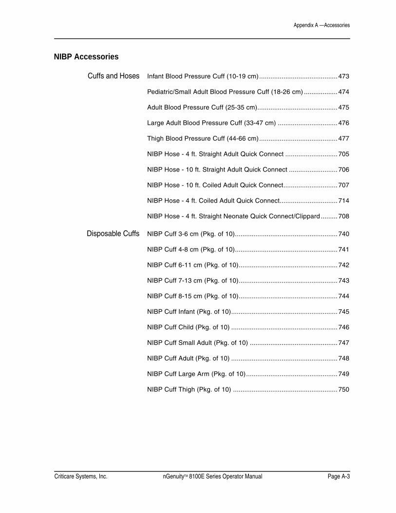
Criticare Systems, Inc. nGenuityTM 8100E Series Operator Manual Page A-3
Appendix A —Accessories
NIBP Accessories
Cuffs and Hoses Infant Blood Pressure Cuff (10-19 cm).......................................... 473
Pediatric/Small Adult Blood Pressure Cuff (18-26 cm) .................. 474
Adult Blood Pressure Cuff (25-35 cm)........................................... 475
Large Adult Blood Pressure Cuff (33-47 cm) ................................ 476
Thigh Blood Pressure Cuff (44-66 cm).......................................... 477
NIBP Hose - 4 ft. Straight Adult Quick Connect ............................ 705
NIBP Hose - 10 ft. Straight Adult Quick Connect .......................... 706
NIBP Hose - 10 ft. Coiled Adult Quick Connect............................. 707
NIBP Hose - 4 ft. Coiled Adult Quick Connect............................... 714
NIBP Hose - 4 ft. Straight Neonate Quick Connect/Clippard ......... 708
Disposable Cuffs NIBP Cuff 3-6 cm (Pkg. of 10)....................................................... 740
NIBP Cuff 4-8 cm (Pkg. of 10)....................................................... 741
NIBP Cuff 6-11 cm (Pkg. of 10)..................................................... 742
NIBP Cuff 7-13 cm (Pkg. of 10)..................................................... 743
NIBP Cuff 8-15 cm (Pkg. of 10)..................................................... 744
NIBP Cuff Infant (Pkg. of 10)......................................................... 745
NIBP Cuff Child (Pkg. of 10) ......................................................... 746
NIBP Cuff Small Adult (Pkg. of 10) ............................................... 747
NIBP Cuff Adult (Pkg. of 10) ......................................................... 748
NIBP Cuff Large Arm (Pkg. of 10)................................................. 749
NIBP Cuff Thigh (Pkg. of 10) ........................................................ 750

Appendix A —Accessories
Page A-4 nGenuityTM 8100E Series Operator Manual Criticare Systems, Inc.
Temperature Probes
Reusable Probes General Purpose Rectal/Esophageal ............................................ 420
Banjo Style Probe ......................................................................... 421
Skin Surface Probe ....................................................................... 422
Disposable Probes Skin Surface Probe ....................................................................... 437
General Purpose Rectal/Esophageal ............................................ 438
Temperature Interconnect Cable ................................................... 439
Temperature Starter Kit (1 ea. 439, 438, 437)............................... 440
Gas Monitoring Accessories
Sampling Devices Sampling Lines (Box of 25) ........................................................ 625N
Disposable Nasal Cannula (Box of 10) ......................................... 624
Divided Nasal Cannula (Box of 10) ............................................... 628
Oral/Nasal Sampling Cannula ....................................................... 637
Endotracheal Adapter, Straight (Box of 10) ................................... 616
Endotracheal Adapter, Elbow (Box 10) ......................................... 617
WaterChek™ 2+ water trap (Box of 30) ................................938F-NC
Scavenging Kit (Exhaust Line & Adapter) ..................................... 655
Scavenging Kit (Exhaust Line & Adapter) International...............655-I

Criticare Systems, Inc. nGenuityTM 8100E Series Operator Manual Page A-5
Appendix A —Accessories
Calibration Accessories Cal Gas (5% CO2, Balance N2) .................................................... 621
Cal Gas (10% CO2, Balance N2) .................................................. 622
Regulator ...................................................................................... 623
Regulator Tube ............................................................................. 613
Cal Gas Aerosol (5% CO2, Balance N2) ....................................... 641
Cal Gas Aerosol (10% CO2, Balance N2) ..................................... 642
Calibration Kits CO2 only ....................................................................................... 612
5% CO2 cylinder, 10% CO2 cylinder,regulator with tubing, plastic storage case
Other Accessories Available
Printer Paper (5 Rolls) P/N 40065B002 ........................................ 553
Fuses......................................................................... P/N 82013B002
Battery ....................................................................... P/N 80519B001
Adaptor Plate (GCX Mounting) .................................. P/N 42194B001
GCX Wall Mount(Does not include wall channel & adaptor plate.) .............. CT-0024-01B
Adapter Plate (GCX Monitoring) ................................................. 1081
Roll Stand and Adapter Plate...................................................... 1091
Carry Case ................................................................................. 1092
Power Cord (Domestic US) ........................................................... 989Power Cord (United Kingdom) ................................................ 989-UKPower Cord (International) ..................................................... 989-INTPower Cord (Unterminated) .................................................... 989-UT

Appendix A —Accessories
Page A-6 nGenuityTM 8100E Series Operator Manual Criticare Systems, Inc.
Publications nGenuity 8100E Series Operator’s Manual - English .................. 1447nGenuity 8100E Series Operator’s Manual - French ................. 1447FnGenuity 8100E Series Operator’s Manual - German .............. 1447GnGenuity 8100E Series Operator’s Manual - Italian ................... 1447InGenuity 8100E Series Operator’s Manual - Portuguese..........1447PnGenuity 8100E Series Operator’s Manual - Spanish ...............1447SnGenuity 8100E Series Operator’s Manual - Russian ...............1447R
nGenuity 8100E Series Service Manual - English....................... 1448

Criticare Systems, Inc. nGenuityTM 8100E Series Operator Manual Page B-1
Appendix B — Alternate Care Defaults
Alternate Care Defaults
The nGenuity 8100E Series monitor has the capability to install either a set of five (5) hospital configuration defaults or a set of five (5) alternate care defaults. The desired default set is programmed at the factory before a unit is first shipped. It is be possible to switch between the sets at any time by using the correct password entry.
Press and hold the DEFAULT key, then enter the password (LIA608) to display the Set Unit Defaults screen (See Figure B-1: ”Set Unit Defaults Screen”). When powering up a new monitor, the EEPROM is loaded with the 5 hospital default configurations.
Figure B-1: Set Unit Defaults Screen
From this display, press and hold the DEFAULT key again. The Install Configuration Defaults screen displays. (See Figure B-2: ”Install Configuration Defaults Screen”).
Figure B-2: Install Configuration Defaults Screen
The Install Configuration Defaults screen permits choosing which set of 5 defaults are available to the user.
Set Unit Defaults
Replace all configurationand alarm settings withunit default settings.
SELECTEDITACCEPT
CUSTOM DEFAULTSSTD DEFAULTSSTD DEFAULTSSTD DEFAULTSSTD DEFAULTS
CANCEL
Install Configuration Defaults
Replace the current set ofconfiguration defaults witha different set of defaults.
SELECT
ACCEPTHOSPITAL DEFAULTSALT CARE DEFAULTS
CANCEL

Appendix B —Alternate Care Defaults
Page B-2 nGenuityTM 8100E Series Operator Manual Criticare Systems, Inc.
The selection procedure works the same as in the previous screens.
1. WIth the SELECT feature highlighted, press the menu knob to select from HOSPITAL DEFAULTS to ALT CARE DEFAULTS (or vice versa).
2. Turn the menu knob to select ACCEPT. The message Action Completed appears. Press the menu knob to effect the change.
When the alternate care facility defaults (ALT CARE DEFAULTS) are installed, the Restore Unit Defaults screen list the possible configuration settings for alternate care facilities with their descriptions. (See Figure B-3: ”Restore Unit Defaults”.) The descriptions are limited to 15 characters each and are in English only.
Figure B-3: Restore Unit Defaults
Restore Unit Defaults
Replace all configurationand alarm settings withunit default settings.
SELECT
ACCEPTECG BP SPO2 TMPECG BP SPO2BP AND SPO2SPO2 ONLYBP ONLY
CANCEL

Criticare Systems, Inc. nGenuityTM 8100E Series Operator Manual Page B-3
Appendix B —Alternate Care Defaults
Configuration Settings for Alternate Care Facilities
The configuration settings for the five alternate care setup defaults are the same as the basic hospital configuration settings except for the following, grouped by menu:
PARAMS Menu Settings
PRINT Menu Settings
Setting ECG/BP/SPO2/TMP ECG/BP/SPO2 BP AND SPO2SPO2 ONLY BP ONLY
Heart Rate Tone Volume
1 1 1 1 1
ECG ON ON ON ON ONECG Cable 3 lead 3 lead n/a n/a n/aECG Filter Monitor Monitor n/a n/a n/aECG Pace detect OFF OFF n/a n/a n/aECG Sensitivity MEDIUM MEDIUM n/a n/a n/aNIBP ON ON ON OFF ONNIBP Tone NONE NONE NONE NONE NONENIBP Cycle Time 5 minutes 5 minutes 5 minutes n/a OFFSpO2 ON ON ON ON OFFRespiration ON ON OFF OFF OFFTemp ON OFF OFF OFF OFFCO2 ON OFF OFF OFF OFF
Setting ECG/BP/SPO2/TMP ECG/BP/SPO2 BP AND SPO2 SPO2 ONLY BP ONLYPrint Type Graphical Graphical Tabular Tabular TabularAlarm Print OFF OFF OFF OFF OFFBP Print Tabular Tabular Tabular OFF OFFInterval Print Off Off Off Off OffInterval Print Type Tabular Tabular Tabular Tabular TabularSnapshot Size 6 seconds 6 seconds 6 seconds 6 seconds 6 secondsHistory Size 6 seconds 6 seconds 6 seconds 6 seconds 6 secondsWaveform 1 ECG II ECG II ECG II ECG II ECG IIGain x1.0 x1.0 x1.0 x1.0 x1.0Waveform 2 PLETH PLETH PLETH PLETH PLETHGain x1.0 x1.0 x1.0 x1.0 x1.0Printer Speed 25.0 MM/SEC 25.0 MM/SEC 25.0 MM/SEC 25.0 MM/SEC 25.0 MM/SECSerial Type Tabular Tabular Tabular Tabular TabularSerial Format CUSP CUSP CUSP CUSP CUSPBaudrate 38400 38400 38400 38400 38400

Appendix B —Alternate Care Defaults
Page B-4 nGenuityTM 8100E Series Operator Manual Criticare Systems, Inc.
DISPLAY Menu Settings
ALARMS Menu Settings
Other Alarm Settings
Setting ECG/BP/SPO2/TMP ECG BP SPO2 BP AND SPO2 SPO2 ONLY BP ONLYWaveform 1 ECG II,x1,25,25 ECG II,x1,25,25 OFF OFF OFFWaveform 2 Cascade Cascade OFF OFF OFFWaveform 3 Cascade Cascade PLETH,x1,25,25 PLETH,x1,25,25 OFFWaveform 4 PLETH,x1,25,25 PLETH,x1,25,25 OFF OFF OFFWaveform 5 OFF OFF OFF OFF OFFWaveform 6 OFF OFF OFF OFF OFF
Alarm Settings Adult High Adult Low Ped High Ped Low Neo High Neo LowHeart Rate 150 40 150 40 180 90SpO2 OFF 90 OFF 90 OFF 90NIBP Systolic 200 50 200 50 140 50NIBP Diastolic 100 40 100 40 80 30Temperature 100.0 °F
37.8 °C94.0 °F34.4 °C
100.0 °F37.8 °C
94.0 °F34.4 °C
100.0 °F37.8 °C
94.0 °F34.4 °C
Respiration 44 4 36 4 60 14CO2 Inspired OFF OFF OFF OFF 10 mmHg
1.5 %1.5 kPa10.0Torr
OFF
CO2 Expired 55 mmHg7.5 %
7.5 kPa56.0 Torr
15 mmHg2.0 %
2.0 kPa15.5 Torr
55 mmHg7.5 %
7.5 kPa56.0 Torr
15 mmHg2.0 %
2.0 kPa15.5 Torr
55 mmHg7.5 %
7.5 kPa56.0 Torr
5 mmHg1.0 %
1.0 kPa5.5 Torr
(Both Adult and Ped) ValueAlarm Volume 3Apnea 20 secondsECG Lead Fail Medium

Criticare Systems, Inc. nGenuityTM 8100E Series Operator Manual Page C-1
Appendix C — Arrhythmia and ST Analysis
Arrhythmia and ST Analysis Software
This appendix describes the optional software extension for the nGenuity 8100E Series monitor. The functions described here must be purchased as a separate upgrade if not originally available with your monitor.
Description The arrhythmia and ST analysis software extension has the capability to measure ST segment deviations and generate arrhythmia alerts for common ventricle arrhythmia conditions. The arrhythmia and ST alerts can also have user specified alarm levels.
Automatic or user adjustable ST measurement points are provided. The monitor measures ST segments continuously from the real-time waveform collected by the internal ECG module. ST elevations are reported on-screen as current numerical values, as short term graphs and long term trends. The arrhythmia and ST analysis is fully integrated with the standard ECG package of the monitor. The standard ECG alarms and ECG lead switching is available when using this feature.
Intended Use This software package is intended for use by physicians to assist with the detection of ventricular arrhythmias and deviations in ST segment elevations that may indicate the presence of myocardial ischemia.
The monitor provides detection of only specific conditions within a defined range of physiological parameters as stated in these instructions. The physician is responsible for the interpretation of the monitored data and alerts that are made available.
Compatibility The arrhythmia and ST features are available through keycode activation on all nGenuity 8100E Series monitors.
The feature can be purchased and activated at any time. Normally the keycode is entered as part of the original manufacturer’s configuration when purchasing the arrhythmia and ST model version and should not need to be entered again.

Appendix C —Arrhythmia and ST Analysis
Page C-2 nGenuityTM 8100E Series Operator Manual Criticare Systems, Inc.
Software Agreement Each monitor using the arrhythmia and ST algorithm requires a specific software licenses separate from the express right to use the operating system software of the monitor. Attempting to access the arrhythmia and ST feature without pass codes obtained through the manufacturer is illegal and may void your authorization to use the monitor. The arrhythmia and ST license cannot be transferred between monitors, but it can be transferred with the monitor as part of a legal sale of the equipment.
The user is prohibited from tampering with the keycode lock out, bypassing the keycode protection, duplicating or otherwise making copies of the arrhythmia and ST software extension. If the arrhythmia and ST software becomes damaged or nonfunctional it can be restored by the manufacturer. If a damaged monitor has a valid arrhythmia and ST license and requires software replacement, the customer is charged only for the service order and not for a new software license.
Activation The analysis keycode setting appears in the service window of the nGenuity 8100E Series monitors. Contact your dealer or CSI customer service for more information.
In case of accidentally selecting the keycode, simply turn off the monitor without completing the key code entry. The keycode will not be overwritten unless you enter the complete keycode. For 8100E Series models that do not include the arrhythmia and ST analysis feature the message Invalid Keycode appears next to the setting.
NOTE: The same service password is used on all nGenuity 8100E Series monitors. Each monitor has a unique keycode to activate the analysis feature.

Criticare Systems, Inc. nGenuityTM 8100E Series Operator Manual Page C-3
Appendix C —Arrhythmia and ST Analysis
Compliance This analysis software has been developed using a real time ST and arrhythmia analysis data base. Analysis features have been developed in accordance with its quality control practices and procedures in place to review potential hazards as they relate to software.
The combined capability of the integral ECG module and the analysis software comply with EC 60601-2-27 ECG Safety Standards.
Transient Power The nGenuity 8100E Series monitor has been tested with AC power line transients per the levels specified in EN 60601-1-2. AC power line transients in excess of EN 60601-1-2 limits may affect the proper operation of this device. If interference from the power line or ground is suspected, this can be confirmed by unplugging the monitor and running on the internal battery. Power line transient interference is likely to disappear while running on battery.
Lead Off Detection Lead-off detection in the 8100E Series monitor applies the following possible range of signals to the electrodes:
20 V DC Max w/ No load across electrodes
0.05 uA Max (LA, RA, LL, V) w/ Electrode shorted to RL
0.20 uA Max (RL) w/ Four electrodes shorted to RL
Respiration The trans-thoracic impedance respiration circuit generates a 65 kHz sinusoidal waveform across the respiration electrodes with an amplitude of 0.356 V peak-peak (0.712 mA @ 500 ohm impedance between lead wire connections).
Sudden Changes InHeart Rate
A step change in heart rate from 80 to 40 BPM or from 80 to 120 BPM will be displayed on the 8100 heart rate display in ten seconds or less (tested per AAMI EC-13 Clause 4.1.2.1 (f): 105 BPM ascending rate target, 54 BPM descending rate target).
Time to alarm when the ECG input changes from an 80 BPM normal sinus rhythm to a 180 BPM ventricular tachycardia (Hi Alarm = 100 BPM) is less than five seconds.
The waveform specified in AAMI EC-13, Figure 3a (80 BPM ventricular bigeminy), when applied to the 8100, displays as 80 BPM. Waveforms b, c, & d from Figure 3 (in EC-13) have not been applied to this product.

Appendix C —Arrhythmia and ST Analysis
Page C-4 nGenuityTM 8100E Series Operator Manual Criticare Systems, Inc.
Method of Analysis The analysis feature is provided by means of a software plug-in designed to work directly with the ECG module of the nGenuity 8100E Series monitor. The ECG waveform is digitized in the ECG module and the signal is made available to the main processor where it is analyzed. The analysis feature also provides additional digital filtering of the ECG waveform.
The displayed heart rate is based upon a 32 beat average of the R to R interval. During periods of rapid changes in the heart rate, a 4 beat average displays until the change subsides and the 32 beat average then resumes.
Figure C-1: Deflection Points on ECG Lead II
The monitor provides real-time analysis and generates alert messages for several defined conditions. The analysis program incorporates functions that determine heart rate, identify QRS beats, measure ST segment levels, perform rhythm analysis, detect ventricular ectopy, and detect ventricular fibrillation.
ST elevation levels for lead III, and augmented leads aVR, aVL, and aVF are derived from leads I and II.
The ventricular fibrillation detection algorithm processes ECG waveform in sections of 1.5 seconds. Waveform sections are evaluated using time domain methods of analysis. If three consecutive sections fail to pass linear relationship testing the waveform is flagged as ventricular fibrillation.
P
Q
S
T
R
S-T SegmentP-R Segment
Q-T IntervalP-R Interval

Criticare Systems, Inc. nGenuityTM 8100E Series Operator Manual Page C-5
Appendix C —Arrhythmia and ST Analysis
Cautions and Warnings
• Physiological variations in the patient population generate a nearly infinite range of possible ECG waveform morphologies. In some cases, the 8100E Series may occasionally not alarm or alarm inappropriately for some arrhythmia waveforms. High risk patients must be kept under close surveillance.
• The monitor does not report the presence of atrial or supra-ventricular arrhythmia events.
• The accurate measurement range for arrhythmia beat detection is 20 to 250 beats per minute. The monitor reports ECG heart rates from 250 to 300 beats per minute only when the arrhythmia feature is turned off. The arrhythmia feature is not intended for use with neonates with high heart rates.
• The presence of tall T waves (greater than 80% of the R wave) may be counted as double beats resulting in a heart rate twice the actual rate.
• The nGenuity arrhythmia analysis algorithms are only intended to detect ventricular arrhythmias.
• Always monitor patients with a pacemaker very closely, since the nGenuity monitor may count at the pacemaker rate during cardiac arrest or some arrhythmias.
WARNING ! !
CAUTION ! !

Appendix C —Arrhythmia and ST Analysis
Page C-6 nGenuityTM 8100E Series Operator Manual Criticare Systems, Inc.
Specifications ECGConnectors: 3 or 5 Lead, Standard AAMI
Lead Selection: 3-Lead; I, II, III5-Lead; I, II, III, aVR, aVL, aVF, V
ECG Sensitivity Low 0.5, Medium 1.0, High 2.0ECG Beat Detection Range: 0.25mV to 5mV
Frequency Response: Diagnostic; 0.05 - 100 Hz (-3db)Monitor; 0.50 - 40 Hz (-3db) ST Filter; 0.05 to 40 Hz (-3db)
Protection: Electrosurgery, HF Equipment, and use of Defibrillator
Pacemaker: Detection/Rejection
Heart RateSource: Smart Switching;
ECG (primary), Pleth, NIBP,Range (with arrhythmia detection): 20-300 bpm (ECG, Pleth)
30-240 bpm (NIBP)Range (arrhythmia off): 20-300 bpm (ECG, Pleth)
30-240 bpm (NIBP)Accuracy: ± 1 bpm or 1%, unspecified > 250 bpm
ST AnalysisLead Views: I, II, III, aVR, aVL, aVF, V
Elevation Accuracy: greater of ±0.2 mm or 5%Method: 16 beat averageRange: -6.0 mm to +6.0 mm
Resolution: 0.1 mm
Arrhythmia DetectionPVC Detection: Rates from 2 to 255 per minute
Runs: 2 to 6Ventricle Tachycardia Alarm: Adjustable, range 90 to 200 bpm
High Priority Alarms: Heart Rate, Asystole, Tachycardia, Ventricular Fibrillation, Bradycardia, Ventricular Tachycardia
DisplayMain Display Numerical PVC Rate,
ST elevation numerics for 3 leadsWaveforms: Up to 6 ECG waveforms, selectable.
Elevation Graphs: 3-leads recorded in waveform slotsTime Scales 5, 10, 25 30, 60 minutesVertical Scale ±1 mm to ±6 mm
TrendsGraphical and Tabular ST-I, ST-II, ST-III, ST-AVR, ST-AVL,
ST-AVF, ST-V, PVC Rate

Criticare Systems, Inc. nGenuityTM 8100E Series Operator Manual Page C-7
Appendix C —Arrhythmia and ST Analysis
Interface Screens The analysis extension uses the same interface and controls as the standard ECG feature of the monitor. The heart rate numerical box is modified to provide main screen display of ST segment elevations and PVC rate.
An additional configuration is available for waveform slot 2 and 3 that allows display of historical ST segment elevations for three selectable lead views.
Figure C-2: Main Screen Display
ALARMS PARAMS DISPLAYALARMS PARAMS DISPLAY
AdultAdultV000 - NO ADMITV000 - NO ADMITSPO2: SENSORSPO2: SENSOR
ADM/DIS CONFIG PRINTADM/DIS CONFIG PRINTAUG-07-05 14:12:59AUG-07-05 14:12:59
SpO2SpO2
IIII
%
aVRaVR
MAP mmHgMAP mmHg CYCLE OFFCYCLE OFF
1mV1mV BPMBPM
Br/mBr/m
1mV1mV
6060
9898
97.797.7
2020
- +- +
149/106149/106 (127)(127) AGE 01:00 AGE 01:00
Fo
ECGECGRESPRESP
PVC Rate 2 /minPVC Rate 2 /min
II -1.5 II -1.5 mmmmI -2.0 I -2.0 mmmmV 1.0 V 1.0 mmmm
STST
Low SpO2 Alarm 90%Low SpO2 Alarm 90%
ECG:LEADS OFF
BP:CHECK CUFF

Appendix C —Arrhythmia and ST Analysis
Page C-8 nGenuityTM 8100E Series Operator Manual Criticare Systems, Inc.
Setup Windows ALARMSSelect Other Alarms Setups from the ALARMS menu to access the two additional settings windows for ST and Arrhythmia. The arrhythmia alarms window will not be available if arrhythmia is turned OFF in the PARAMS menu.
Select Arrhythmia Setup to set the alarms for arrhythmia.
Figure C-3: Select Arrhythmia Setup
Alarm priorities that appear in yellow are fully adjustable. Asystole, VFIB, and VTACH are permanently set to high priority.
Figure C-4: Extended ALARMS Window for Arrhythmia
EXITAlarm Volume 5ECG Lead Fail MEDIUMPatient size Adult HIGH LOWHeart Rate 150 40SpO2 OFF 90NIBP Systolic 200 50NIBP Diastolic 100 30NIBP Mean 150 50Temperature °F 100.0 93.0Respiration 36 OFFCO2 Inspired kPa 1.5 OFFCO2 Expired kPa 7.5 1.5Apnea 60 seconds
Other Alarm Setups Arrhythmia Setup
UNITS HIGH LOW ALARM PRIORITYHeart Rate BPM 150 40 HIGH
PVC Rate /min 2 DISABLEDPVC Run 2 DISABLED
Asystole HIGHVFIB HIGHVTACH Min. HR 160 HIGHVT > 2 MEDIUMBigeminy MESSAGETrigeminy MESSAGEPVC Couplet MESSAGEIrregular HR MESSAGEArrhythmia Relearn MESSAGE
<<< BACK
EXIT

Criticare Systems, Inc. nGenuityTM 8100E Series Operator Manual Page C-9
Appendix C —Arrhythmia and ST Analysis
Select ST Setup to set the alarms for arrhythmia.
Figure C-5: Select ST Setup
The ST elevation alarms are fully adjustable for each lead view.
NOTE: The ST alarms window shown below do not appear if ST is turned off in the PARAMS menu.
Figure C-6: Extended ALARMS Window with ST
EXITAlarm Volume 5ECG Lead Fail MEDIUMPatient size Adult HIGH LOWHeart Rate 150 40SpO2 OFF 90NIBP Systolic 200 50NIBP Diastolic 100 30NIBP Mean 150 50Temperature °F 100,0 93,0Respiration 36 OFFCO2 Inspired kPa 1.5 OFFCO2 Expired kPa 7.5 1.5Apnea 60 seconds
Other Alarm Setups ST Setup
UNITS HIGH LOW ALARM PRIORITYST-I mm 2.0 -2.0 DISABLEDST-II mm 2.0 -2.0 DISABLEDST-III mm 2.0 -2.0 DISABLEDST-AVR mm 2.0 -2.0 DISABLEDST-AVL mm 2.0 -2.0 DISABLEDST-AVF mm 2.0 -2.0 DISABLEDST-V mm 2.0 -2.0 DISABLED
Use ST I settings for all Leads YES
<<< BACK
EXIT

Appendix C —Arrhythmia and ST Analysis
Page C-10 nGenuityTM 8100E Series Operator Manual Criticare Systems, Inc.
PARAMS
Figure C-7: PARAMS Window with ST / Arrhythmia
The lead view and color selections in the PARAMS menu allow adjustment of the ST elevation graph that can be set to appear in waveform slot 2 or 3.
NOTE: An additional ST window is accessed by selecting Other Params Menus. This additional window allows manual setting of the ST measurement points and is discussed later in this appendix.
DISPLAY
Figure C-8: Display Settings Window with ST
EXIT
Heart Rate HR Source Smart NIBP ¤ Heart Rate Tone Vol 5 NIBP tone NONE
ECG ¤ Temperature ON ¤ Cable 5 lead Unit of measure F Pace detect OFF Filter Monitor ST / Arrhythmia Sensitivity MEDIUM Arrhythmia ON Relearn NOSpO2 ¤ ST ON Average 12 seconds Lead 1 ECG II ¤ Search time 20 seconds Lead 2 ECH I ¤ Lead 3 ECG V ¤Respiration ON Other Params MenusCO2 ON ¤ No Action Unit of measure mmHg N2O compensation OFF
o
EXIT TYPE GAIN SWEEP SIZE MM/SECWaveform 1 ECG II x1.0 25.0 50mmWaveform 2 ST HIST x1.0 25.0 25mmWaveform 3 ECG III x1.0 25.0 25mmWaveform 4 PLETH x1.0 25.0 12mmWaveform 5 RESP x1.0 25.0 12mmWaveform 6 OFF x1.0 25.0 12mm
External Display OFF
Duration ScaleST Graph 1 10 minutes +/- 2 mmST Graph 2 10 minutes +/- 2 mmST Graph 3 10 minutes +/- 2 mm

Criticare Systems, Inc. nGenuityTM 8100E Series Operator Manual Page C-11
Appendix C —Arrhythmia and ST Analysis
Select ST HIST for the TYPE in the waveform slot. A historical graph can be displayed for three lead views. The lead views and colors are adjusted in the PARAMS menu, while duration and scale of the graph is adjusted in the DISPLAY menu.
ST/Arrhythmia Defaults
Alarms Settings,Arrhythmia Setup
Alarm Settings Alarm Priority
Alarm Type Range
Default
Options DefaultAdult Pediatric NeonateHeart Rate High 80-250 150 150 180 High HighHeart Rate Low 20-160 40 40 90 High High
PVC Rate 2-59 2 2 2 Disabled, High, Medium, Low, Advisory, Silent Medium, Message
Disabled
PVC Run 2-6 2 2 2 Disabled, High, Medium, Low, Advisory, Silent Medium, Message
Disabled
Asystole na na na na High HighVFIB na na na na High HighVTACH 90-200 160 160 180 High HighVT > 2 na na na na Disabled, High, Medium, Low,
Advisory, Silent Medium, MessageMedium
Bigeminy na na na na Disabled, High, Medium, Low, Advisory, Silent Medium, Message
Message
Trigeminy na na na na Disabled, High, Medium, Low, Advisory, Silent Medium, Message
Message
PVC Couplet
na na na na Disabled, High, Medium, Low, Advisory, Silent Medium, Message
Message
Irregular HR
na na na na Disabled, High, Medium, Low, Advisory, Silent Medium, Message
Message
Arrhythmia Relearn
na na na na Disabled, High, Medium, Low, Advisory, Silent Medium, Message
Message
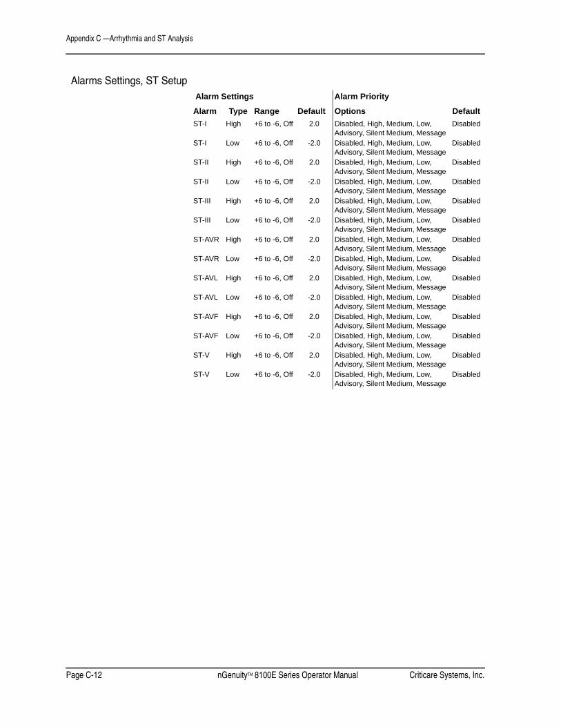
Appendix C —Arrhythmia and ST Analysis
Page C-12 nGenuityTM 8100E Series Operator Manual Criticare Systems, Inc.
Alarms Settings, ST Setup Alarm Settings Alarm Priority
Options DefaultAlarm Type Range DefaultST-I High +6 to -6, Off 2.0 Disabled, High, Medium, Low,
Advisory, Silent Medium, MessageDisabled
ST-I Low +6 to -6, Off -2.0 Disabled, High, Medium, Low, Advisory, Silent Medium, Message
Disabled
ST-II High +6 to -6, Off 2.0 Disabled, High, Medium, Low, Advisory, Silent Medium, Message
Disabled
ST-II Low +6 to -6, Off -2.0 Disabled, High, Medium, Low, Advisory, Silent Medium, Message
Disabled
ST-III High +6 to -6, Off 2.0 Disabled, High, Medium, Low, Advisory, Silent Medium, Message
Disabled
ST-III Low +6 to -6, Off -2.0 Disabled, High, Medium, Low, Advisory, Silent Medium, Message
Disabled
ST-AVR High +6 to -6, Off 2.0 Disabled, High, Medium, Low, Advisory, Silent Medium, Message
Disabled
ST-AVR Low +6 to -6, Off -2.0 Disabled, High, Medium, Low, Advisory, Silent Medium, Message
Disabled
ST-AVL High +6 to -6, Off 2.0 Disabled, High, Medium, Low, Advisory, Silent Medium, Message
Disabled
ST-AVL Low +6 to -6, Off -2.0 Disabled, High, Medium, Low, Advisory, Silent Medium, Message
Disabled
ST-AVF High +6 to -6, Off 2.0 Disabled, High, Medium, Low, Advisory, Silent Medium, Message
Disabled
ST-AVF Low +6 to -6, Off -2.0 Disabled, High, Medium, Low, Advisory, Silent Medium, Message
Disabled
ST-V High +6 to -6, Off 2.0 Disabled, High, Medium, Low, Advisory, Silent Medium, Message
Disabled
ST-V Low +6 to -6, Off -2.0 Disabled, High, Medium, Low, Advisory, Silent Medium, Message
Disabled

Criticare Systems, Inc. nGenuityTM 8100E Series Operator Manual Page C-13
Appendix C —Arrhythmia and ST Analysis
ST / ArrhythmiaMonitoring Parameters
Display Settings
Parameter Selectable Options Factory DefaultArrhythmia On, Off OffST On, Off OffLead I ECG I, ECG II, ECG III, ECG aVR, ECG aVL,
ECG aVF, ECG V, OffECG II
Lead 2 ECG I, ECG II, ECG III, ECG aVR, ECG aVL, ECG aVF, ECG V, Off
ECG I
Lead 3 ECG I, ECG II, ECG III, ECG aVR, ECG aVL, ECG aVF, ECG V, Off
ECG V
Setting Selectable Options Factory DefaultST Graph 1
Duration 5, 10, 15, 30, 60 minutes 10 minutesScale +/- 1, 2, 3, 4, 5, 6 mm +/- 2 mm
ST Graph 2Duration 5, 10, 15, 30, 60 minutes 20 minutes
Scale +/- 1, 2, 3, 4, 5, 6 mm +/- 2 mmST Graph 3
Duration 5, 10, 15, 30, 60 minutes 30 minutesScale +/- 1, 2, 3, 4, 5, 6 mm +/- 2 mm
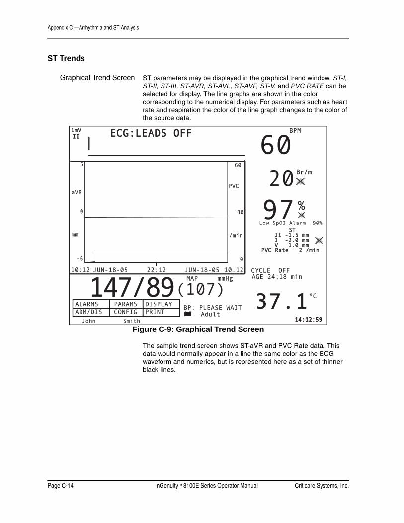
Appendix C —Arrhythmia and ST Analysis
Page C-14 nGenuityTM 8100E Series Operator Manual Criticare Systems, Inc.
ST Trends
Graphical Trend Screen ST parameters may be displayed in the graphical trend window. ST-I, ST-II, ST-III, ST-AVR, ST-AVL, ST-AVF, ST-V, and PVC RATE can be selected for display. The line graphs are shown in the color corresponding to the numerical display. For parameters such as heart rate and respiration the color of the line graph changes to the color of the source data.
Figure C-9: Graphical Trend Screen
The sample trend screen shows ST-aVR and PVC Rate data. This data would normally appear in a line the same color as the ECG waveform and numerics, but is represented here as a set of thinner black lines.
ALARMS PARAMS DISPLAYALARMS PARAMS DISPLAYADM/DIS CONFIG PRINT ADM/DIS CONFIG PRINT
BP: PLEASE WAITBP: PLEASE WAIT
14:12:5914:12:59
IIII
ºCºC
%
MAP mmHgMAP mmHgCYCLE OFFCYCLE OFF
Br/mBr/m
1mV1mV BPMBPM
6060
979797
37.137.1
2020
ECG:LEADS OFFECG:LEADS OFF
147/89147/89(107)(107)- +- +
John SmitJohn Smith
6060
10:1210:12 JUN-18-05JUN-18-05 10:1210:12JUN-18-05JUN-18-05
-6-6 0
30300
6
22:1222:12
PVCPVC
/min/minmmmm
aVRaVR
AdultAdult
AGE 24;18 minAGE 24;18 min
Low SpO2 Alarm 90%
PVC Rate 2 /minPVC Rate 2 /min
II -1.5 II -1.5 mmmmI -2.0 I -2.0 mmmmV 1.0 V 1.0 mmmm
STST

Criticare Systems, Inc. nGenuityTM 8100E Series Operator Manual Page C-15
Appendix C —Arrhythmia and ST Analysis
Tabular Trend Markersand Messages
Various messages appear in the tabular trend when ST and Arrhythmia are activated:
ARRH BEGIN ARRH ENDST SETUP CHANGE
• When arrhythmia events begin and end, the messages ARRH BEGIN and ARRH END appear in the table.
• When the ST setup is changed the message ST SETUP CHANGE is recorded in the trend table.
Data Format with ST The table includes trend data for ST-I, ST-II, ST-III, ST-aVR, ST-aVL, ST-aVF, ST-V, and PVC Rate/min._______________________________________________________
27-JAN-05 11:45+ 11:45 11:44+ 11:44 11:43+ 11:43RATE BPM 60E 60E 60E 60E ARRH STSpO2 % 99 99 99 98 BEGIN SETUPNIBP SYS mmHg 135 CHANGE
DIA mmHg 95MAP mmHg 115
TEMP °F 98.6 98.6 98.6 OFFRESP Br/m 20 20 20 20ST-I mm -2.0 -2.0 -2.0 -2.0ST-II mm -1.5 -1.5 -1.5 -1.5ST-III mm -1.0 -1.0 -1.0 -1.0ST-AVR mm -0.5 -0.5 -0.5 -0.5ST-AVL mm 0.0 0.0 0.0 0.0ST-AVF mm 0.5 0.5 0.5 0.5ST-V mm 1.0 1.0 1.0 1.0PVC Rate/min 2 2 2 2
_______________________________________________________Figure C-10: Trend Display Table with ST
For complete information on trend data, see “Trends” in Section 6.
Clinical Preparation The ST/Arrhythmia uses the same patient setup procedures as the normal ECG measurement techniques explained in “Patient Monitoring” in Section 4.
Accessories The ST/Arrhythmia software requires no special accessories or equipment. Use the standard ECG accessory kit that came with your monitor for best results.
Appendix C —Arrhythmia and ST Analysis
Page C-16 nGenuityTM 8100E Series Operator Manual Criticare Systems, Inc.
Clinical Use Refer to “ECG Monitoring (Electocardiogram)” in Section 4 for basic instructions for ECG monitoring.
Pacemaker Detection With the pacemaker detector turned ON in the 8100E Series monitor, the system detects and rejects pacemaker pulses ranging from ± 2 to ± 700 mV amplitude and 0.1 to 2.0 ms duration. Heart rates are properly displayed over this range of pacemaker operation.
Defibrillation When used with CSI-approved, AAMI-Compliant ECG electrodes, the 8100E Series monitor recovers display of the ECG waveform within five seconds following defibrillation.
Arrhythmia Detection Whenever a potential Asystole, VFIB, and/or VTACH is detected, a marker (similar to an admit/discharge marker) is placed in the tabular trends showing the approximate period of the event. The text is ARRH START and ARRH END regardless of which arrhythmia type is identified.
When ST/Arrhythmia is enabled using the keycode, the alarm messages are altered as follows:
• ECG LOST is replaced with ASYSTOLE.
• HIGH PULSE RATE is replaced with TACHYCARDIA when ECG is the heart rate source.
• LOW PULSE RATE is replaced with BRADYCARDIA when ECG is the heart rate source.
ST Segment Analysis The ST segment analysis can be activated independently from the arrhythmia feature.The feature provides both automatic and manual adjustment of the ST segment points. When the ST feature is activated additional settings appears in the menus and the ST elevation unit markers appears in the upper right corner of the main display. The ST values remain dashed until ST deviations are reported.
Description A graphical method of setting the ISO, J, and ST points for ST analysis is available through the PARAMS screen. This allows the user to adjust the reference and measurement points with the menu knob. An averaged QRS is displayed for each lead view.

Criticare Systems, Inc. nGenuityTM 8100E Series Operator Manual Page C-17
Appendix C —Arrhythmia and ST Analysis
A ST historical graph display is available for waveform slots 2 and 3 that is divided into 3 boxes. Each box contains a graphical plot of the ST elevation numbers for each lead view. The time scale is adjustable from 5, 10, 15, 30, or 60 minutes and the vertical scale is adjustable from ±1 mm to ±6 mm in 1 mm steps. The graphs are updated once per minute with the most recent data displayed at the right hand end.
• If the ST value is dashed then the graph will be railed low.
• If the ST value is greater than the vertical scale allows, the graph will rail high.
Starting ST 1. Confirm that the ST/Arrhythmia extension has been activated on your monitor.
2. Select the PARAMS softkey on the main menu and enter the first window. If the ST/Arrhythmia extension is present, additional settings now appear on the right side of the window.
3. Rotate the menu knob past the end of the ECG settings. The highlight cursor then jumps to the beginning of the ST /Arrhythmia parameter settings.
4. Highlight ST and press the menu knob to select.
5. Rotate the menu knob and turn to ON.
NOTE: Arrhythmia must be on in order to turn ST on.
ST Filter Activation of ST analysis automatically switches filtering to the ST Filter setting.
Learn There is a setting in the PARAMS menu to command a rhythm re-learn. During the re-learn period (16 beats), the ST values are dashed.
ST, J, and ISO Points In the PARAMS menu access the Other Params Menu and open the Set ST, J, and ISO points window.
The user can adjust the ISO, J, and ST points. These are used by the algorithm when making ST deviation calculations.
The ISO point identifies the isoelectric baseline elevation from which the ST calculation is made. It is usually located just before the Q wave.

Appendix C —Arrhythmia and ST Analysis
Page C-18 nGenuityTM 8100E Series Operator Manual Criticare Systems, Inc.
The ST point identifies the position where the ST segment ends, usually just before the rising edge of the T wave. It is at this point that the measurement is taken to determine the vertical height or depression relative to the ISO point selected along the isoelectric baseline.
The J point is a reference point from which the ISO and ST points are located. It is usually located at the point where the S wave returns to baseline.
Automatic ST SegmentDetection
The default ST point is located 60 milliseconds after the J point. The default ISO point is located about 100 milliseconds before the J point. The algorithm uses the default positions until it has collected enough QRS data to reposition the J and ISO points. The ST point stays fixed at a location 60 milliseconds from the J point unless the user changes it manually.
Figure C-11: Main Display with ST Adjustment Window
ALARMS PARAMS DISPLAYALARMS PARAMS DISPLAY
AdultAdultV000 - NO ADMITV000 - NO ADMITSPO2: SENSORSPO2: SENSOR
ADM/DIS CONFIG PRINTADM/DIS CONFIG PRINTAUG-07-05 14:12:59AUG-07-05 14:12:59
IIII
%
MAP mmHgMAP mmHg CYCLE OFFCYCLE OFF
1mV1mV BPMBPM
Br/mBr/m
6060
9898
97.797.7
2020
- +- +
149/106149/106 (127)(127) AGE 01:00 minAGE 01:00 min
Fo
ECGECG
PVC Rate 2 /minPVC Rate 2 /min
II -1.5 II -1.5 mmmmI -2.0 I -2.0 mmmmV 1.0 V 1.0 mmmm
STST
Low SpO2 Alarm 90%Low SpO2 Alarm 90%
EXITEXIT
0 ms0 ms
-300 ms-300 ms
30 ms30 ms
ISO ptISO ptIIII
I
NONONONOV
J ptJ pt ST ptST pt
<<< BACK<<< BACK
Set J PointSet J Point
ST and ISO are offsetST and ISO are offsetfrom the J pointfrom the J point
Set ISO PointSet ISO Point
Set ST PointSet ST Point
Reset to Defaults?Reset to Defaults?Cancel Changes?Cancel Changes?
Select a point to adjust, turn the knob to move the Select a point to adjust, turn the knob to move the vertical line. Changes take effect immediately.vertical line. Changes take effect immediately.

Criticare Systems, Inc. nGenuityTM 8100E Series Operator Manual Page C-19
Appendix C —Arrhythmia and ST Analysis
ST, J, and ISO PointManual Adjustment
Enter the ST point adjustment window by selecting Other Params Menus from the PARAMS window.
The ST point adjustment window provides an averaged QRS waveform for each lead view selected in the PARAMS menu. The QRS waveform is updated if the current QRS deflections change.
Rotate the menu knob to highlight an adjustment point. Press the menu knob and then turn to change the location of the selected point.
The window can be reset to defaults which allow the monitor to resume automatic determination of the ST segment. The adjustments can also be canceled allowing the previous settings to return.
• Any manually set J, ST, or ISO point is discarded on the next power cycle.

Appendix C —Arrhythmia and ST Analysis
Page C-20 nGenuityTM 8100E Series Operator Manual Criticare Systems, Inc.
Tabular Printing A header is printed containing the monitor model, the operating software revision, the time and date, and the patient information. The title for each parameter follows.
Numerical values for all current parameters are printed. The sample below shows a tabular print out with ST and PVC Rate values.
Figure C-12: Tabular ST Printout

Criticare Systems, Inc. nGenuityTM 8100E Series Operator Manual Page C-21
Appendix C —Arrhythmia and ST Analysis
ST and Arrhythmia Alarm Description
Many of the alarms listed below have adjustable alarm priority levels. The options are high, medium, silent medium, low, advisory and informational message.
The message level priority is the same as the informational level messages generated by the system software. Message level alerts have no audible component.
Activation of arrhythmia and ST Analysis feature adds two new alarm categories that are not associated with the standard features of the 8100 monitor. Medium level alarms without an audible component and advisory level alerts are selectable alarm level options for ST and arrhythmia alarms.
Advisory level alerts have the same visual component as informational messages, but also include a tone. Each advisory level audible burst consists of 2 pulses. The frequency is 300 Hz and the repeat cycle is approximately 5 minutes. The pitch of the advisory level tone is lower than the high, medium, and low level alarms discussed in “Alarms and Messages” in Section 5.
Alarm Conditions The ST segment elevation must be beyond the alarm limits for at least 60 consecutive seconds before the alarm is activated. Conversely, the ST segment elevation must be within the alarm limits for another 60 seconds before the alarm is cleared.
• ST elevation conditions must exist consecutively for one minute before an ST elevation alarm is generated.
• There is an ST/Arrhythmia alarm icon located in the upper corner of the main screen located near the PVC Rate numerical display. The icon appears when one or more of the ST or PVC alarms are disabled in the alarm menus.
CAUTION ! !

Appendix C —Arrhythmia and ST Analysis
Page C-22 nGenuityTM 8100E Series Operator Manual Criticare Systems, Inc.
Arrhythmia AlertsPriority Description
ECG: ASYSTOLE High Asystole alarm appears when a heart beat has not been detected for 10 seconds. This message replaces the ECG LOST message normally reported by the monitor.
ECG: VFIB High Ventricular fibrillation alarm appears when the ECG signal has no detectable QRS or T components. The waveform is irregular in shape, interval and amplitude for a period of 4 seconds.
ECG: VFIB/ASYS High A period of 4 seconds composed of asystole and ventricular fibrillation conditions.
ECG: VTACH High Eight or more PVC classified beats detected at a rate above the user defined limit for ventricular tachycardia.
TACHYCARDIA High This message replaces the HIGH PULSE RATE message normally reported by the monitor while the smart heart rate is sourced from ECG data.
BRADYCARDIA High This message replaces the LOW PULSE RATE message normally reported by the monitor while the smart heart rate is sourced from ECG data.
ECG: VT 2 RUN Adjustable At minimum, 2 seconds of PVC classified beats detected at a rate above the selected ventricular tachycardia limit has been detected.
ECG: BIGEMINY Adjustable Indicates that two or more cycles of a ventricular beat followed by a non-ventricular beat have occurred.
ECG: TRIGEMINY Adjustable Indicates that two or more cycles of a ventricular beat followed by two non-ventricular beats have occurred.
ECG:COUPLETS Adjustable Indicates two consecutive ventricular beats detected with non-ventricular beats occurring before and after the pair.
ECG:IRREG. HR Adjustable Consistently irregular heart rate with 6 consecutive RR intervals that vary by 100 milliseconds or more.
ECG:HIGH PVC/MIN Adjustable The number of detected premature ventricular complexes per minute has exceeded the preselected threshold.
ECG:PVC RUN Adjustable The number of consecutively detected premature ventricular complexes has exceeded the preselected threshold.
ECG: LEARNING Adjustable The monitor is acquiring sixteen QRS beats in order to identify the patient’s normal rhythm.

Criticare Systems, Inc. nGenuityTM 8100E Series Operator Manual Page C-23
Appendix C —Arrhythmia and ST Analysis
ST AlertsPriority Description
LOW ST on I Adjustable The ST segment elevation on lead view I is below the limit selected in the ST alarms menu.
HIGH ST on I Adjustable The ST segment elevation on lead view I is above the limit selected in the ST alarms menu.
LOW ST on II Adjustable The ST segment elevation on lead view II is below the limit selected in the ST alarms menu.
HIGH ST on II Adjustable The ST segment elevation on lead view II is above the limit selected in the ST alarms menu.
LOW ST on III Adjustable The ST segment elevation on lead view III is below the limit selected in the ST alarms menu.
HIGH ST on III Adjustable The ST segment elevation on lead view III is above the limit selected in the ST alarms menu.
LOW ST on AVR Adjustable The ST segment elevation on lead view aVR is below the limit selected in the ST alarms menu.
HIGH ST on AVR Adjustable The ST segment elevation on lead view aVR is above the limit selected in the ST alarms menu.
LOW ST on AVL Adjustable The ST segment elevation on lead view aVL is below the limit selected in the ST alarms menu.
HIGH ST on AVL Adjustable The ST segment elevation on lead view aVL is above the limit selected in the ST alarms menu.
LOW ST on AVF Adjustable The ST segment elevation on lead view aVF is below the limit selected in the ST alarms menu.
HIGH ST on AVF Adjustable The ST segment elevation on lead view aVF is above the limit selected in the ST alarms menu.
LOW ST on V Adjustable The ST segment elevation on lead view V is below the limit selected in the ST alarms menu.
HIGH ST on V Adjustable The ST segment elevation on lead view V is above the limit selected in the ST alarms menu.