NFPA 68 - thermofick.comthermofick.com/assets/catalogos/Normas/NFPA/NFPA 68-2007 Explosion...NFPA...
96
NFPA 68 Standard on Explosion Protection by Deflagration Venting 2007 Edition NFPA, 1 Batterymarch Park, Quincy, MA 02169-7471 An International Codes and Standards Organization
Transcript of NFPA 68 - thermofick.comthermofick.com/assets/catalogos/Normas/NFPA/NFPA 68-2007 Explosion...NFPA...

NFPA 68
Standard on Explosion Protection by
Deflagration Venting
2007 Edition
NFPA, 1 Batterymarch Park, Quincy, MA 02169-7471 An International Codes and Standards Organization

IMPORTANT NOTICES AND DISCLAIMERS CONCERNING NFPA DOCUMENTS
NOTICE AND DISCLAIMER OF LIABILITY CONCERNING THE USE OF NFPA DOCUMENTS
NFPA codes, standards, recommended practices, and guides, of which the document contained herein is one, are de-veloped through a consensus standards development process approved by the American National Standards Institute.This process brings together volunteers representing varied viewpoints and interests to achieve consensus on fire andother safety issues. While the NFPA administers the process and establishes rules to promote fairness in the develop-ment of consensus, it does not independently test, evaluate, or verify the accuracy of any information or the soundnessof any judgments contained in its codes and standards.
The NFPA disclaims liability for any personal injury, property or other damages of any nature whatsoever, whetherspecial, indirect, consequential or compensatory, directly or indirectly resulting from the publication, use of, or relianceon this document. The NFPA also makes no guaranty or warranty as to the accuracy or completeness of any informationpublished herein.
In issuing and making this document available, the NFPA is not undertaking to render professional or other servicesfor or on behalf of any person or entity. Nor is the NFPA undertaking to perform any duty owed by any person or entityto someone else. Anyone using this document should rely on his or her own independent judgment or, as appropriate,seek the advice of a competent professional in determining the exercise of reasonable care in any given circumstances.
The NFPA has no power, nor does it undertake, to police or enforce compliance with the contents of this document.Nor does the NFPA list, certify, test or inspect products, designs, or installations for compliance with this document.Any certification or other statement of compliance with the requirements of this document shall not be attributable tothe NFPA and is solely the responsibility of the certifier or maker of the statement.
ADDITIONAL NOTICES AND DISCLAIMERS
Updating of NFPA Documents
Users of NFPA codes, standards, recommended practices, and guides should be aware thatthese documents may be superseded at any time by the issuance of new editions or may beamended from time to time through the issuance of Tentative Interim Amendments. An offi-cial NFPA document at any point in time consists of the current edition of the documenttogether with any Tentative Interim Amendments and any Errata then in effect. In order todetermine whether a given document is the current edition and whether it has been amendedthrough the issuance of Tentative Interim Amendments or corrected through the issuance ofErrata, consult appropriate NFPA publications such as the National Fire Codes® SubscriptionService, visit the NFPA website at www.nfpa.org, or contact the NFPA at the address listedbelow.
Interpretations of NFPA Documents
A statement, written or oral, that is not processed in accordance with Section 6 of the Reg-ulations Governing Committee Projects shall not be considered the official position of NFPAor any of its Committees and shall not be considered to be, nor be relied upon as, a FormalInterpretation.
Patents
The NFPA does not take any position with respect to the validity of any patent rightsasserted in connection with any items which are mentioned in or are the subject of NFPAcodes, standards, recommended practices, and guides, and the NFPA disclaims liability forthe infringement of any patent resulting from the use of or reliance on these documents.Users of these documents are expressly advised that determination of the validity of any suchpatent rights, and the risk of infringement of such rights, is entirely their own responsibility.
NFPA adheres to applicable policies of the American National Standards Institute withrespect to patents. For further information contact the NFPA at the address listed below.
Law and Regulations
Users of these documents should consult applicable federal, state, and local laws and reg-ulations. NFPA does not, by the publication of its codes, standards, recommended practices,and guides, intend to urge action that is not in compliance with applicable laws, and thesedocuments may not be construed as doing so.
Copyrights
This document is copyrighted by the NFPA. It is made available for a wide variety of bothpublic and private uses. These include both use, by reference, in laws and regulations, anduse in private self-regulation, standardization, and the promotion of safe practices andmethods. By making this document available for use and adoption by public authorities andprivate users, the NFPA does not waive any rights in copyright to this document.
Use of NFPA documents for regulatory purposes should be accomplished through adop-tion by reference. The term “adoption by reference” means the citing of title, edition, andpublishing information only. Any deletions, additions, and changes desired by the adoptingauthority should be noted separately in the adopting instrument. In order to assist NFPA infollowing the uses made of its documents, adopting authorities are requested to notify theNFPA (Attention: Secretary, Standards Council) in writing of such use. For technical assis-tance and questions concerning adoption of NFPA documents, contact NFPA at the addressbelow.
For Further Information
All questions or other communications relating to NFPA codes, standards, recommendedpractices, and guides and all requests for information on NFPA procedures governing itscodes and standards development process, including information on the procedures forrequesting Formal Interpretations, for proposing Tentative Interim Amendments, and forproposing revisions to NFPA documents during regular revision cycles, should be sent toNFPA headquarters, addressed to the attention of the Secretary, Standards Council, NFPA,1 Batterymarch Park, P.O. Box 9101, Quincy, MA 02269-9101.
For more information about NFPA, visit the NFPA website at www.nfpa.org.

pSs
2
pbetwyw
had
irr
ttg
tnTT
pe“ir
esFwas
68–1
Copyright © 2007 National Fire Protection Association. All Rights Reserved.
NFPA 68
Standard on
Explosion Protection by Deflagration Venting
2007 Edition
This edition of NFPA 68, Standard on Explosion Protection by Deflagration Venting, was pre-ared by the Technical Committee on Explosion Protection Systems. It was issued by thetandards Council on December 1, 2006, with an effective date of December 20, 2006, andupersedes all previous editions.
This edition of NFPA 68 was approved as an American National Standard on December 20,006.
Origin and Development of NFPA 68NFPA 68, Standard on Explosion Protection by Deflagration Venting, was first adopted as a tem-
orary standard in 1945. In 1954, the temporary standard was replaced with a guide thatrought together all of the best available information on the fundamentals and parameters ofxplosions, the data developed by small-scale tests, the interpretation of the results of theseests, and the use of vents and vent closures that were current at the time. This informationas then related to “rules of thumb” vent ratio recommendations that were used for manyears. Some of the vents that were designed using these rules of thumb functioned well; othersere never put to the test.
Since 1954, extensive experimentation has been done in Great Britain and Germany andas added to the existing information. The U.S. Bureau of Mines also did some work in thisrea. However, the work was not completed because the group involved was reassigned toifferent programs.
In 1974, NFPA 68 was revised, and the work done in Great Britain and Germany wasncluded with the hope that the new information would provide a means for calculating ventatios with a greater degree of accuracy than that provided by the rules of thumb. The 1978evision included substantial data that were more valuable in designing explosion relief vents.
In 1979, the committee began a major effort to rewrite the guide in order to incorporatehe results of the test work done in Germany. In addition, the 1988 edition contained rewrit-en text that more clearly explained the various parameters that affect the venting of defla-rations.
The 1994 edition of NFPA 68 was completely rewritten to more effectively communicatehe principles of venting deflagrations to users. Revisions to each chapter improved the orga-ization of information within the document without changing the venting methodology.he thrust of this revision was to improve the user friendliness and adoptability of the guide.hese changes were made to clarify this complex technology.
The 1998 edition introduced updated terminology to be consistent with current industrialractice. New information was added on the effects of vent ducts, calculation methods forvaluating those effects, and the effects of vent discharge. The revision also incorporated theweak roof-to-shell” joint design as a means of venting silos and bins and providing newnformation on explosions in elongated vessels. It also clarified the provisions for securingestraint panels.
The 2002 edition represented a complete revision of the guide and included updated andnhanced treatment for deflagration venting design for dusts and hybrid mixtures. The revi-ion also included new vent design equations based upon the methodology developed byactory Mutual Research Corporation. In addition to the generalized correlation for dustsere new methods to evaluate the effects of vent ducts, partial volumes, vent panel inertia,nd initially elevated pressures. All design guidelines for gas mixtures were combined into aingle chapter, and the document underwent Manual of Style revision as well.

68–2 EXPLOSION PROTECTION BY DEFLAGRATION VENTING
2
The 2007 edition represents a complete revision, including a change from guide to standard. The new “Standardon Explosion Protection by Deflagration Venting” now provides mandatory requirements for the design, location,installation, maintenance, and use of devices and systems that vent combustion gases and pressures from deflagrations.The Committee incorporated a new chapter on performance-based design that enables users to present alternativedesign methods to satisfy the requirements for gas and mist mixtures, for dusts, and for hybrid mixtures. The Commit-tee also revised the generalized correlation for dusts on the basis of a review of additional experimental data. Thisreview enabled the Committee to support revisions to the basic equation, along with changes to the equations forlow-inertia vent closures, panel inertia, partial volume, initially elevated pressures, and vent ducts. The Committee alsoadded a new chapter on inspection and maintenance.
007 Edition
JK&MA
RLAJJSIDMI
D&
G
G
DD
M
E[
R
FLVU
G
68–3COMMITTEE PERSONNEL
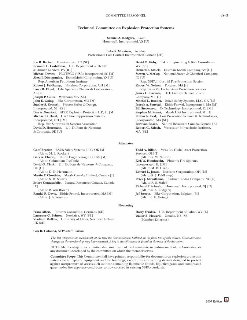
Technical Committee on Explosion Protection Systems
Samuel A. Rodgers, ChairHoneywell, Incorporated, VA [U]
Luke S. Morrison, Secretary
Professional Loss Control Incorporated, Canada [SE]oe R. Barton, Fountaintown, IN [SE]enneth L. Cashdollar, U.S. Department of HealthHuman Services, PA [RT]ichael Davies, PROTEGO (USA) Incorporated, SC [M]lexi I. Dimopoulos, ExxonMobil Corporation, VA [U]
Rep. American Petroleum Instituteobert J. Feldkamp, Nordson Corporation, OH [M]arry D. Floyd, Ciba Specialty Chemicals Corporation,L [U]
oseph P. Gillis, Westboro, MA [SE]ohn E. Going, Fike Corporation, MO [M]tanley S. Grossel, Process Safety & Design,ncorporated, NJ [SE]an A. Guaricci, ATEX Explosion Protection L.P., FL [M]ichael D. Hard, Hard Fire Suppression Systems,
ncorporated, OH [IM]Rep. Fire Suppression Systems Association
avid D. Herrmann, E. I. DuPont de NemoursCompany, DE [U]
Alternates
(Alt. to J. A. Senecal)
Nonvoting
K [SE]
uy R. Colonna, NFPA Staff Liaison
Tc
Na
Csag
David C. Kirby, Baker Engineering & Risk Consultants,WV [SE]Richard S. Malek, Eastman Kodak Company, NY [U]Steven A. McCoy, National Starch & Chemical Company,IN [U]
Rep. NFPA Industrial Fire Protection SectionRobert W. Nelson, Pocasset, MA [I]
Rep. Swiss Re, Global Asset Protection ServicesJames O. Paavola, DTE Energy/Detroit EdisonCompany, MI [U]Mitchel L. Rooker, BS&B Safety Systems, LLC, OK [M]Joseph A. Senecal, Kidde-Fenwal, Incorporated, MA [M]Bill Stevenson, Cv Technology, Incorporated, FL [M]Stephen M. Stuart, Marsh USA Incorporated, MI [I]Erdem A. Ural, Loss Prevention Science & Technologies,Incorporated, MA [SE]Bert von Rosen, Natural Resources Canada, Canada [E]Robert G. Zalosh, Worcester Polytechnic Institute,MA [SE]
eof Brazier, BS&B Safety Systems, LLC, OK [M](Alt. to M. L. Rooker)
ary A. Chubb, Chubb Engineering, LLC, KS [M](Alt. to Columbian TecTank)
avid G. Clark, E. I. DuPont de Nemours & Company,E [U]
(Alt. to D. D. Herrmann)artin P. Clouthier, Marsh Canada Limited, Canada [I]
(Alt. to S. M. Stuart)ttore Contestabile, Natural Resources Canada, CanadaE]
(Alt. to B. von Rosen)andal R. Davis, Kidde-Fenwal, Incorporated, MA [M]
Todd A. Dillon, Swiss Re, Global Asset ProtectionServices, OH [I]
(Alt. to R. W. Nelson)Kirk W. Humbrecht, Phoenix Fire Systems,Incorporated, IL [IM]
(Alt. to M. D. Hard)Edward L. Jones, Nordson Corporation, OH [M]
(Alt. to R. J. Feldkamp)Peter J. McWilliams, Eastman Kodak Company, NY [U]
(Alt. to R. S. Malek)Richard F. Schwab, Honeywell, Incorporated, NJ [U]
(Alt. to S. A. Rodgers)Jef Snoeys, Fike Corporation, Belgium [M]
(Alt. to J. E. Going)
ranz Alfert, Inburex Consulting, Germany [SE]aurence G. Britton, Neolytica, WV [SE]ladimir Molkov, University of Ulster, Northern Ireland,
Harry Verakis, U.S. Department of Labor, WV [E]Walter B. Howard, Omaha, NE [SE]
(Member Emeritus)
his list represents the membership at the time the Committee was balloted on the final text of this edition. Since that time,hanges in the membership may have occurred. A key to classifications is found at the back of the document.
OTE: Membership on a committee shall not in and of itself constitute an endorsement of the Association orny document developed by the committee on which the member serves.
ommittee Scope: This Committee shall have primary responsibility for documents on explosion protectionystems for all types of equipment and for buildings, except pressure venting devices designed to protectgainst overpressure of vessels such as those containing flammable liquids, liquefied gases, and compressedases under fire exposure conditions, as now covered in existing NFPA standards.
2007 Edition

68–4 EXPLOSION PROTECTION BY DEFLAGRATION VENTING
Contents
Chapter 1 Administration ................................. 68– 61.1 Scope ............................................... 68– 61.2 Purpose ............................................ 68– 61.3 Application ........................................ 68– 61.4 Equivalency ....................................... 68– 61.5 Retroactivity ....................................... 68– 61.6 Conversion Factors .............................. 68– 61.7 Symbols ............................................ 68– 71.8 Pressure ............................................ 68– 7
Chapter 2 Referenced Publications .................... 68– 72.1 General ............................................ 68– 72.2 NFPA Publications ............................... 68– 72.3 Other Publications .............................. 68– 72.4 References for Extracts in Mandatory
Sections ............................................ 68– 7
Chapter 3 Definitions ...................................... 68– 83.1 General ............................................ 68– 83.2 NFPA Official Definitions ...................... 68– 83.3 General Definitions ............................. 68– 8
Chapter 4 General Requirements ....................... 68– 94.1 Goal ................................................. 68– 94.2 Objectives ......................................... 68– 94.3 Compliance Options ............................ 68– 9
Chapter 5 Performance-Based Design Option ....... 68– 95.1 General Requirements ......................... 68– 95.2 Performance Criteria ........................... 68–10
Chapter 6 Fundamentals of Venting ofDeflagrations ................................... 68–10
6.1 Basic Concepts ................................... 68–106.2 Mixtures ........................................... 68–106.3 Enclosure Design and Support ............... 68–106.4 Enclosure Length-to-Diameter Ratio
and Vent Variables ............................... 68–126.5 Vent Closure Operation ........................ 68–126.6 Consequences of a Deflagration ............. 68–136.7 Effects of Vent Inertia ........................... 68–136.8 Effects of Vent Discharge Ducts .............. 68–136.9 Venting with Flame Arresting and
Particulate Retention ........................... 68–14
Chapter 7 Venting Deflagrations of GasMixtures and Mists ............................ 68–14
7.1 Introduction ...................................... 68–147.2 Venting of Gas or Mist Deflagration in
Low-Strength Enclosures ...................... 68–147.3 Venting of Gas or Mist Deflagration in
High-Strength Enclosures ..................... 68–167.4 Effects of Vent Ducts ............................ 68–17
2007 Edition
7.5 Effects of Initial Turbulence andInternal Appurtenances forEnclosures with Initial PressuresNear Atmospheric ............................... 68–17
7.6 Effects of Initial Elevated Pressure .......... 68–17
Chapter 8 Venting of Deflagrations of Dustsand Hybrid Mixtures ......................... 68–18
8.1 Introduction ...................................... 68–188.2 Venting by Means of Low-Inertia Vent
Closures ............................................ 68–188.3 Effects of Partial Volume ....................... 68–198.4 Effects of Initially Elevated Pressure ........ 68–208.5 Effects of Vent Ducts ............................ 68–218.6 Bins, Hoppers, and Silos ....................... 68–218.7 Venting of Dust Collectors Using Bags,
Filters, or Cartridges ............................ 68–228.8 Fireball Dimensions ............................. 68–238.9 Venting Internal to a Building with
Flame-Arresting andParticulate-Retention Device .................. 68–24
8.10 Deflagration Venting of EnclosuresInterconnected with Pipelines ................ 68–24
Chapter 9 Venting of Deflagrations of Gasesand Dusts in Pipes and DuctsOperating at or NearAtmospheric Pressure ........................ 68–24
9.1 Introduction ...................................... 68–249.2 Design .............................................. 68–249.3 Multiple Deflagration Vents on a Pipe
or Duct ............................................. 68–25
Chapter 10 Details of Deflagration Vents andVent Closures ................................. 68–26
10.1 Normally Open Vents ........................... 68–2610.2 Normally Closed Vents ......................... 68–2610.3 Types of Building or Room Vent
Closures ............................................ 68–2610.4 Restraints for Large Panels .................... 68–2610.5 Equipment Vent Closures ...................... 68–2610.6 Flame-Arresting and
Particulate-Retention Vent Systems .......... 68–27
Chapter 11 Inspection and Maintenance .............. 68–2711.1 General ............................................ 68–2711.2 Design Parameters and
Documentation .................................. 68–2711.3 Installation ........................................ 68–2711.4 Inspection ......................................... 68–2811.5 Vent Closure Design Parameters ............. 68–2811.6 Inspection Reports .............................. 68–2811.7 Record Keeping .................................. 68–2811.8 Management of Change ....................... 68–28
68–5CONTENTS
11.9 Maintenance ...................................... 68–2811.10 Employee Training .............................. 68–28
Annex A Explanatory Material ........................... 68–29
Annex B Fundamentals of Deflagration ............... 68–52
Annex C Guidelines for MeasuringDeflagration Indices of Dusts andGases .............................................. 68–56
Annex D Fundamental Burning Velocities forSelect Flammable Gases in Air .............. 68–60
Annex E Deflagration Characteristics of SelectFlammable Gases ............................... 68–62
Annex F Deflagration Characteristics of SelectCombustible Dusts .............................. 68–63
Annex G Calculation Method for CorrectionFactor Due to Increased VentPanel Mass ....................................... 68–65
Annex H Alternative Vent Area Methodology ........ 68–68
Annex I Research Reports and SupportingDocuments ........................................ 68–72
Annex J Effect of Partial Volumes on Buildings— Example Problem ............................ 68–72
Annex K Bibliography ..................................... 68–73
Annex L Informational References ..................... 68–76
Index ............................................................. 68–78
2007 Edition

68–6 EXPLOSION PROTECTION BY DEFLAGRATION VENTING
NFPA 68
Standard on
Explosion Protection by Deflagration Venting
2007 Edition
IMPORTANT NOTE: This NFPA document is made available foruse subject to important notices and legal disclaimers. These noticesand disclaimers appear in all publications containing this documentand may be found under the heading “Important Notices and Dis-claimers Concerning NFPA Documents.” They can also be obtainedon request from NFPA or viewed at www.nfpa.org/disclaimers.
NOTICE: An asterisk (*) following the number or letterdesignating a paragraph indicates that explanatory materialon the paragraph can be found in Annex A.
A reference in brackets [ ] following a section or paragraphindicates material that has been extracted from another NFPAdocument. As an aid to the user, the complete title and editionof the source documents for extracts in mandatory sections ofthe document are given in Chapter 2 and those for extracts ininformational sections are given in Annex L. Editorial changesto extracted material consist of revising references to an ap-propriate division in this document or the inclusion of thedocument number with the division number when the refer-ence is to the original document. Requests for interpretationsor revisions of extracted text shall be sent to the technicalcommittee responsible for the source document.
Information on referenced publications can be found inChapter 2 and Annexes I, K, and L.
Chapter 1 Administration
1.1* Scope. This standard applies to the design, location, instal-lation, maintenance, and use of devices and systems that vent thecombustion gases and pressures resulting from a deflagrationwithin an enclosure so that structural and mechanical damageis minimized.
1.2* Purpose. The purpose of this standard is to provide theuser with criteria for design, installation, and maintenance ofdeflagration vents and associated components.
1.3* Application. This standard applies where the need fordeflagration venting has been established.
1.3.1 This standard does not apply to detonations, bulk auto-ignition of gases, or unconfined deflagrations, such as open-air or vapor cloud explosions.
1.3.2* This standard does not apply to devices that are de-signed to protect storage vessels against excess internal pres-sure due to external fire exposure or to exposure to other heatsources.
1.3.3 This standard does not apply to emergency vents forpressure generated during runaway exothermic reactions,self-decomposition reactions, internal vapor generation re-sulting from electrical faults, or pressure generation mecha-nisms other than deflagration.
1.3.4 This standard does not apply to venting of deflagrationsin oxygen-enriched atmospheres or other oxidants unless sup-ported by specific test data.
2007 Edition
1.4 Equivalency. Nothing in this standard is intended to pre-vent the use of systems, methods, or devices of equivalent orsuperior quality, strength, fire resistance, effectiveness, dura-bility, and safety over those prescribed by this standard.
1.4.1 Technical documentation shall be submitted to the au-thority having jurisdiction to demonstrate equivalency.
1.4.2 The system, method, or device shall be approved for theintended purpose by the authority having jurisdiction.
1.5 Retroactivity.
1.5.1 The provisions of this standard reflect a consensus ofwhat is necessary to provide an acceptable degree of protec-tion from the hazards addressed in this standard at the timethe standard was issued.
1.5.1.1 Unless otherwise specified, the provisions of this stan-dard shall not apply to facilities, equipment, structures, or in-stallations that existed or were approved for construction orinstallation prior to the effective date of the standard. Wherespecified, the provisions of this standard shall be retroactive.
1.5.1.2 In those cases where the authority having jurisdictiondetermines that the existing situation presents an unaccept-able degree of risk, the authority having jurisdiction shall bepermitted to apply retroactively any portions of this standarddeemed appropriate.
1.5.1.3 The retroactive requirements of this standard shall bepermitted to be modified if their application clearly would beimpractical in the judgment of the authority having jurisdic-tion, and only where it is clearly evident that a reasonabledegree of safety is provided.
1.5.2 This standard shall apply to facilities on which construc-tion is begun subsequent to the date of publication of thestandard.
1.5.3 When major replacement or renovation of existing fa-cilities is planned, provisions of this standard shall apply.
1.6 Conversion Factors. The conversion factors in Table 1.6 areuseful for understanding the data presented in this standard.
Table 1.6 Conversion Factors
Parameter Unit Equivalent
Length 1 m 3.28 ft39.4 in.
1 in. 25.4 mm1 ft 305 mm1 µm 1.00 × 10⁻⁶ m
Area 1 m2 10.8 ft2
1 in.2 6.45 cm2
Volume 1 L 61.0 in.3
1 ft3 7.48 U.S. gal1 m3 35.3 ft3
264 U.S. gal1 U.S. gal 3.78 L
231 in.3
0.134 ft3

68–7REFERENCED PUBLICATIONS
Table 1.6 Continued
Parameter Unit Equivalent
Pressure 1 atm 760 mm Hg101 kPa14.7 psi1.01 bar
1 psi 6.89 kPa1 N/m2 1.00 Pa1 bar 100 kPa
14.5 psi0.987 atm
1 kg/cm2 14.2 psi1 kg/m2 0.205 lb/ft2 (psf)
Energy 1 J 1.00 W-sec1 Btu 1055 J1 J 0.738 ft-lb
KG and KSt 1 bar-m/sec 47.6 psi-ft/secconversion 1 psi-ft/sec 0.021 bar-m/sec
Concentration 1 ozavoirdupois/ft3
1000 g/m3
Key to abbreviations in Table 1.6:atm = atmosphereBtu = British thermal unitcm = centimeterft = footg = gramgal = gallonHg = mercuryin. = inchJ = joulekg = kilogramkPa = kilopascalL = liter
lb = poundm = metermm = millimeterN = newtonoz = ouncePa = pascalpsf = pounds per square footpsi = pounds per square inchsec = secondW = wattµm = micron (micrometer)
1.7 Symbols. The following symbols are defined for the pur-pose of this standard:
A = area (m2, ft2, or in.2)AS = internal surface area of enclosure (m2 or ft2)Av = vent area (m2 or ft2)C = constant used in venting equations as defined
in each specific usedP/dt = rate of pressure rise (bar/sec or psi/sec)Fr = reaction force constant (lb)KG = deflagration index for gases (bar-m/sec)KSt = deflagration index for dusts (bar-m/sec)Ln = linear dimension of enclosure [m or ft (n = 1,
2, 3)]Lx = distance between adjacent ventsL/D = length to diameter ratio (dimensionless)LFL = lower flammable limit (percent by volume for
gases, weight per volume for dusts and mists)MEC = minimum explosible concentration (g/m3 or
oz/ft3)MIE = minimum ignition energy (mJ)p = perimeter of duct cross-section (m or ft)P = pressure (bar or psi)Pes = enclosure strength (bar or psi)Pex = explosion pressure (bar or psi)Pmax = maximum pressure developed in an unvented
vessel (bar or psi)
P0 = initial pressure (bar or psi)Pred = reduced pressure [i.e., maximum pressure
actually developed during a venteddeflagration (bar or psi)]
Pstat = static activation pressure (bar or psi)dP = pressure differential (bar or psi)Su = fundamental burning velocity (cm/sec)Sf = flame speed (cm/sec)tf = duration of pressure pulse (sec)UFL = upper flammable limit (percent by volume)V = volume (m3 or ft3)
1.8 Pressure. All pressures are gauge pressure unless other-wise specified.
Chapter 2 Referenced Publications
2.1 General. The documents or portions thereof listed in thischapter are referenced within this standard and shall be con-sidered part of the requirements of this document.
2.2 NFPA Publications. National Fire Protection Association,1 Batterymarch Park, Quincy, MA 02169-7471.
NFPA 69, Standard on Explosion Prevention Systems, 2002 edi-tion.
NFPA 654, Standard for the Prevention of Fire and Dust Explo-sions from the Manufacturing, Processing, and Handling of Combus-tible Particulate Solids, 2006 edition.
2.3 Other Publications.
2.3.1 API Publications. American Petroleum Institute, 1220L Street, NW, Washington, DC 20005-4070.
API 650, Welded Steel Tanks for Oil Storage, 1998.
2.3.2 ASME Publications. American Society of MechanicalEngineers, Three Park Avenue, New York, NY 10016-5990.
ASME Boiler and Pressure Vessel Code, 1998.
2.3.3 ASTM Publications. ASTM International, 100 Barr Har-bor Drive, P.O. Box C700, West Conshohocken, PA 19428-2959.
ASTM E 1226, Standard Test Method for Pressure and Rate ofPressure Rise for Combustible Dusts, 2005.
2.3.4 ISO Publications. International Organization for Stan-dardization, 1, rue de Varembè, Case postale 56, CH-1211Geneve 20, Switzerland.
ISO 6184/1, Explosion Protection Systems — Part 1: Determina-tion of Explosion Indices of Combustible Dust in Air, 1985.
2.3.5 Other Publications. Merriam-Webster’s Collegiate Dictionary,11th edition, Merriam-Webster, Inc., Springfield, MA, 2003.
2.4 References for Extracts in Mandatory Sections.
NFPA 53, Recommended Practice on Materials, Equipment, andSystems Used in Oxygen-Enriched Atmospheres, 2004 edition.
NFPA 484, Standard for Combustible Metals, 2006 edition.NFPA 654, Standard for the Prevention of Fire and Dust Explo-
sions from the Manufacturing, Processing, and Handling of Combus-
tible Particulate Solids, 2006 edition.2007 Edition
68–8 EXPLOSION PROTECTION BY DEFLAGRATION VENTING
Chapter 3 Definitions
3.1 General. The definitions contained in this chapter shallapply to the terms used in this standard. Where terms are notdefined in this chapter or within another chapter, they shallbe defined using their ordinarily accepted meanings withinthe context in which they are used. Merriam-Webster’s CollegiateDictionary,11th edition, shall be the source for the ordinarilyaccepted meaning.
3.2 NFPA Official Definitions.
3.2.1* Approved. Acceptable to the authority having jurisdic-tion.
3.2.2* Authority Having Jurisdiction (AHJ). An organization,office, or individual responsible for enforcing the require-ments of a code or standard, or for approving equipment,materials, an installation, or a procedure.
3.2.3 Labeled. Equipment or materials to which has beenattached a label, symbol, or other identifying mark of an orga-nization that is acceptable to the authority having jurisdictionand concerned with product evaluation, that maintains peri-odic inspection of production of labeled equipment or mate-rials, and by whose labeling the manufacturer indicates com-pliance with appropriate standards or performance in aspecified manner.
3.2.4* Listed. Equipment, materials, or services included in alist published by an organization that is acceptable to the au-thority having jurisdiction and concerned with evaluation ofproducts or services, that maintains periodic inspection ofproduction of listed equipment or materials or periodic evalu-ation of services, and whose listing states that either the equip-ment, material, or service meets appropriate designated stan-dards or has been tested and found suitable for a specifiedpurpose.
3.2.5 Shall. Indicates a mandatory requirement.
3.2.6 Should. Indicates a recommendation or that which isadvised but not required.
3.2.7 Standard. A document, the main text of which containsonly mandatory provisions using the word “shall” to indicaterequirements and which is in a form generally suitable formandatory reference by another standard or code or for adop-tion into law. Nonmandatory provisions shall be located in anappendix or annex, footnote, or fine-print note and are not tobe considered a part of the requirements of a standard.
3.3 General Definitions.
3.3.1 Burning Velocity. The rate of flame propagation relativeto the velocity of the unburned gas that is ahead of it.
3.3.1.1 Fundamental Burning Velocity. The burning velocityof a laminar flame under stated conditions of composition,temperature, and pressure of the unburned gas.
3.3.2 Combustible Dust. A combustible particulate solid thatpresents a fire or deflagration hazard when suspended in airor some other oxidizing medium over a range of concentra-tion, regardless of particle size or shape. [654, 2006]
3.3.3 Combustion. A chemical process of oxidation that oc-curs at a rate fast enough to produce heat and usually light inthe form of either a glow or flame.
2007 Edition
3.3.4 Deflagration. Propagation of a combustion zone at avelocity that is less than the speed of sound in the unreactedmedium.
3.3.5 Deflagration Index. Value indicated by the use of vari-able, K. (See 3.3.19, KG, and 3.3.20, KSt.)
3.3.6 Detonation. Propagation of a combustion zone at a ve-locity that is greater than the speed of sound in the unreactedmedium.
3.3.7 Dust. Any finely divided solid, 420 µm or 0.017 in. orless in diameter (that is, material capable of passing through aU.S. No. 40 Standard Sieve).
3.3.8* Enclosure. A confined or partially confined volume.
3.3.9 Equivalent Diameter. See 3.3.18, Hydraulic Diameter.
3.3.10 Explosion. The bursting or rupturing of an enclosureor a container due to the development of internal pressurefrom a deflagration.
3.3.11* Flame Speed. The speed of a flame front relative to afixed reference point.
3.3.12 Flammable Limits. The minimum and maximum con-centrations of a combustible material, in a homogeneous mix-ture with a gaseous oxidizer, that will propagate a flame.
3.3.12.1* Lower Flammable Limit (LFL). The lowest con-centration of a combustible substance in a gaseous oxidizerthat will propagate a flame, under defined test conditions.
3.3.12.2 Upper Flammable Limit (UFL). The highest con-centration of a combustible substance in a gaseous oxidizerthat will propagate a flame.
3.3.13 Flammable Range. The range of concentrations be-tween the lower and upper flammable limits.
3.3.14* Flash Point. The minimum temperature at which aliquid or a solid emits vapor sufficient to form an ignitiblemixture with air near the surface of the liquid or the solid.
3.3.15* Friction Factor, fD . A dimensionless factor relatingpressure drop in a straight duct to velocity and wetted surfacearea.
3.3.16 Fundamental Burning Velocity. See 3.3.1.1.
3.3.17 Gas. The state of matter characterized by completemolecular mobility and unlimited expansion; used synony-mously with the term vapor.
3.3.18* Hydraulic Diameter. A diameter for noncircular crosssections that is determined by 4(A/p), where A is the cross-sectional area normal to the longitudinal axis of the space andp is the perimeter of the cross section.
3.3.19* KG . The deflagration index of a gas cloud.
3.3.20* KSt . The deflagration index of a dust cloud.
3.3.21 Maximum Pressure (Pmax). See 3.3.27.1.
3.3.22 Minimum Explosible Concentration (MEC). The mini-mum concentration of a combustible dust cloud that is ca-pable of propagating a deflagration through a uniform mix-ture of the dust and air under the specified conditions of test.
3.3.23* Minimum Ignition Energy (MIE). The minimumamount of energy released at a point in a combustible mixturethat causes flame propagation away from the point, underspecified test conditions.
drodriguez
Resaltado
drodriguez
Resaltado
drodriguez
Resaltado

68–9PERFORMANCE-BASED DESIGN OPTION
3.3.24 Mist. A dispersion of fine liquid droplets in a gaseousmedium.
3.3.25 Mixture.
3.3.25.1* Hybrid Mixture. A mixture of a flammable gas atgreater than 10 percent of its lower flammable limit witheither a combustible dust or a combustible mist.
3.3.25.2* Optimum Mixture. A specific mixture of fuel andoxidant that yields the most rapid combustion at a specificmeasured quantity or that yields the lowest value of theminimum ignition energy or that produces the maximumdeflagration pressure.
3.3.25.3 Stoichiometric Mixture. A balanced mixture of fueland oxidizer such that no excess of either remains aftercombustion. [53, 2004]
3.3.26* Oxidant. Any gaseous material that can react with afuel (either gas, dust, or mist) to produce combustion.
3.3.27 Pressure.
3.3.27.1 Maximum Pressure (Pmax). The maximum pres-sure developed in a contained deflagration of an opti-mum mixture.
3.3.27.2 Reduced Pressure (Pred). The maximum pressure de-veloped in a vented enclosure during a vented deflagration.
3.3.27.3 Static Activation Pressure (Pstat). Pressure that acti-vates a vent closure when the pressure is increased slowly(with a rate of pressure rise less than 0.1 bar/min =1.5 psi/min).
3.3.28 Rate of Pressure Rise (dP/dt). The increase in pressuredivided by the time interval necessary for that increase to occur.
3.3.28.1* Maximum Rate of Pressure Rise [(dP/dt)max]. Theslope of the steepest part of the pressure-versus-time curverecorded during deflagration in a closed vessel.
3.3.29 Reduced Pressure (Pred). See 3.3.27.2.
3.3.30 Replacement-in-Kind. A replacement that satisfies thedesign specifications. [484, 2006]
3.3.31 Static Activation Pressure (Pstat). See 3.3.27.3.
3.3.32 Strength.
3.3.32.1 Enclosure Strength (Pes). Up to two-thirds the ul-timate strength for low-strength enclosures; for high-strength enclosures the enclosure design pressure suffi-cient to resist Pred .
3.3.32.2 Ultimate Strength. The pressure that results in thefailure of the weakest structural component of an enclosure.
3.3.33 Vapor. See 3.3.17, Gas.
3.3.34 Vent. An opening in an enclosure to relieve the devel-oping pressure from a deflagration.
3.3.35 Vent Closure. A pressure-relieving cover that is placedover a vent.
Chapter 4 General Requirements
4.1 Goal. The goal of this standard shall be to provide effec-tive deflagration venting for enclosures where there is the po-tential for a deflagration.
4.2 Objectives.
4.2.1 Life Safety.
4.2.1.1* Deflagration venting for occupied enclosures shallprevent the structural failure of the enclosure and minimizeinjury to personnel in adjacent areas outside of the enclosure.
4.2.1.2 Deflagration venting for unoccupied enclosures shallprevent the rupture of the enclosure.
4.2.1.3 Deflagration venting shall be arranged to avoid injuryto personnel by the vent discharge.
4.2.2 Property Protection.
4.2.2.1 Deflagration venting shall be designed to limit dam-age of the vented enclosure.
4.2.2.2* Deflagration venting shall be arranged to avoid igni-tion of adjacent property.
4.2.2.3 Deflagration venting shall be arranged to avoid blastdamage to adjacent property.
4.2.2.4 Deflagration venting shall be arranged to avoid pro-jectile damage to adjacent property.
4.2.3 Hazard Analysis.
4.2.3.1 The design basis deflagration hazard scenario shall beidentified and documented.
4.2.3.2 A documented risk evaluation acceptable to the au-thority having jurisdiction shall be permitted to be conductedto determine the level of protection to be provided.
4.3 Compliance Options.
4.3.1 Options. Deflagration venting meeting the goals andobjectives of Sections 4.1 and 4.2 shall be provided in accor-dance with either of the following:
(1) Performance-based provisions of 4.3.2(2) Prescriptive-based provisions of 4.3.3
4.3.2 Performance-Based Design. A performance-based de-sign shall be in accordance with Chapter 5 of this standard.
4.3.3 Prescriptive-Based Design. A prescriptive-based designshall be in accordance with Chapters 6 through 11 of thisstandard.
Chapter 5 Performance-Based Design Option
5.1 General Requirements.
5.1.1* Qualifications. The performance-based design shall beprepared by a person with qualifications acceptable to the au-thority having jurisdiction.
5.1.2 Design Documentation. The design methodology anddata sources shall be documented and maintained for the lifeof the protected enclosure.
5.1.3 Maintenance of Design Features.
5.1.3.1 To continue meeting the performance goals and ob-jectives of this standard, the design features required for eachdeflagration vent shall be maintained for the life of the pro-tected enclosure.
5.1.3.2 Any changes to the design shall require approval ofthe authority having jurisdiction prior to the actual change.
2007 Edition
drodriguez
Resaltado

68–10 EXPLOSION PROTECTION BY DEFLAGRATION VENTING
5.2 Performance Criteria.
5.2.1 Deflagration vent design shall be based on the docu-mented hazard scenario.
5.2.2 Deflagration vents shall limit the reduced pressure(Pred) within an enclosure and any attached vent ducts to meetthe objectives in 4.2.1.1 and 4.2.1.2.
5.2.3 Deflagration Vent Discharge.
5.2.3.1 Combustible materials outside the enclosure shall notattain their ignition temperature from flame or hot gases dis-charged from a deflagration vent.
5.2.3.2* Blast load from deflagration vent discharge shall limitthe risk of damage to exposed structures.
5.2.3.3* Access to spaces into which deflagration vents dis-charge shall be restricted so as to minimize, to a level accept-able to the authority having jurisdiction, the risk of injuryfrom flame, hot gases, hot particles, or projectiles.
5.2.4 Inspection and Maintenance.
5.2.4.1 Deflagration venting shall be regularly inspected andmaintained to confirm the ability of the venting to perform asdesigned.
5.2.4.1.1 If no guidance is given from the performance-baseddesign documents, the requirements of Chapter 11 of thisstandard shall apply.
5.2.4.2 Inspection and maintenance shall be documentedand retained for at least 1 year or the last three inspections.
Chapter 6 Fundamentals of Venting of Deflagrations
6.1* Basic Concepts.
6.1.1* The deflagration index, K, shall be computed from themaximum rate of pressure rise attained by combustion in aclosed vessel with volume, V, and shall be defined by the fol-lowing equation:
KdPdt
V= ⎛⎝⎜
⎞⎠⎟max
/⋅ 1 3 (6.1.1)
6.1.2* For dusts, KSt and Pmax shall be determined in approxi-mately spherical calibrated test vessels of at least 20 L capacityper ASTM E 1226, Standard Test Method for Pressure and Rate ofPressure Rise for Combustible Dusts.
6.1.2.1* It shall be permitted to determine KSt and Pmax perISO 6184/1, Explosion Protection Systems — Part 1: Determinationof Explosion Indices of Combustible Dusts in Air.
6.1.2.2 The owner/user shall be permitted to test the dust withmoisture content and particle size that deviates from the recom-mended conditions established by the method described in 6.1.2or 6.1.2.1, provided a documented assessment acceptable to theauthority having jurisdiction has been performed prior to usingthese KSt and Pmax values to determine vent sizing.
6.1.3* The most accurate value of KG shall be determined di-rectly by test, as outlined in Annex C.
6.1.3.1 If testing cannot be done to determine KG for a par-ticular gas, KG shall be permitted to be approximated by ratio-ing from the KG of propane (100 bar-m/sec) on the basis ofthe corresponding fundamental burning velocity (see Annex D)
2007 Edition
of propane (46 cm/sec) and the fundamental burning veloc-ity of the gas in question. (See Table E.1 for KG values.)
6.1.3.2 For gases, Pmax shall be determined in approximatelyspherical calibrated test vessels of at least 5 L (1.3 gal) capacitywith initially quiescent mixture with low energy ignition source(less than 100 J).
6.2 Mixtures.
6.2.1 Gas Mixtures.
6.2.1.1 Where the hazard consists of a flammable gas mixture,the vent size shall be based on the KG or fundamental burningvelocity of the mixture.
6.2.1.2 Where the gas mixture composition is not certain, thevent size shall be based on the component having the highestKG or fundamental burning velocity.
6.2.2 Dust Mixtures.
6.2.2.1 Where the hazard consists of a dust mixture, the ventsize shall be based on the KSt and Pmax of the mixture.
6.2.2.2 Where the dust mixture composition is not certain,the vent size shall be based on the highest KSt of all compo-nents and the highest Pmax of all components.
6.2.3* Hybrid Mixtures.
6.2.3.1 For hybrid mixtures, the vent size shall be based onthe equivalent mixture KSt as determined by test.
6.2.3.2 Where test data are not available for hybrid mixtureswith gases that have combustion characteristics similar to those ofpropane (fundamental burning velocity ≤1.3 times that of pro-pane) and St-1 and St-2 dusts, the design shall be permitted to bebased upon Pmax = 10 bar and KSt = 500 bar-m/sec.
6.2.4* Foams of Combustible Liquids. Design of deflagrationventing for foams of combustible liquids shall be based ontests performed on the specific foam.
6.3 Enclosure Design and Support.
6.3.1 Enclosure Design Pressure Selection Criteria.
6.3.1.1* Pred shall not exceed two-thirds of the ultimate strengthfor the vented enclosure, provided deformation of the equip-ment can be tolerated.
6.3.1.2 Where deformation cannot be tolerated, Pred shall notexceed two-thirds of the yield strength for the vented enclosure.
6.3.1.3* For enclosures designed using the ASME Boiler andPressure Vessel Code or similar codes, the maximum allowableworking pressure, herein designated as Pmawp , shall be deter-mined by calculation.
6.3.1.3.1 Such determinations shall include an allowable stressfor the enclosure material of construction, which is less than themeasured yield stress and the measured ultimate stress for thematerial of construction.
6.3.1.3.2 Given a Pmawp , Pred shall be selected based on thefollowing conditions as defined by Equation 6.3.1.3.2a orEquation 6.3.1.3.2b:
(1) Permanent deformation, but not rupture, of the enclo-sure can be accepted.
P F Pred u mawp≤ ( )23 ⋅ ⋅ (6.3.1.3.2a)

68–11FUNDAMENTALS OF VENTING OF DEFLAGRATIONS
(2) Permanent deformation of the enclosure cannot beaccepted.
P F Pred y mawp≤ ( )23 ⋅ ⋅ (6.3.1.3.2b)
where:Pred = maximum pressure developed in a vented
enclosure [bar (psi)]Fu = ratio of ultimate stress of the enclosure to the
allowable stress of the enclosure per theASME Boiler and Pressure Vessel Code
Pmawp = enclosure design pressure [bar (psi)] accordingto ASME Boiler and Pressure Vessel Code
Fy = ratio of the yield stress of the enclosure to theallowable stress of the materials ofconstruction of the enclosure per the ASMEBoiler and Pressure Vessel Code
6.3.1.4 Ductile design considerations shall be used for mate-rials subject to brittle failure such as cast iron.
6.3.1.4.1 Special reinforcing shall be considered.
6.3.1.4.2 If such reinforcing is not used, the maximum allow-able design stress shall not exceed 25 percent of the ultimatestrength.
6.3.2* Venting shall be sufficient to prevent the maximum pres-sure that develops within the enclosure, Pred , from exceeding theenclosure strength, Pes , including the dynamic effect of the rateof pressure rise, as expressed by a dynamic load factor (DLF):
PP
DLFredes≤ (6.3.2)
where:Pred = maximum pressure developed during venting
[bar (psi)]Pes = enclosure strength evaluated based on static
pressure calculations for either deformation orburst [bar (psi)]
DLF = Xm/XsXm = maximum dynamic deflectionXs = static deflection or, in other words, the
displacement produced in the system when thepeak load is applied statically
6.3.2.1 In the absence of detailed structural response analysis, itshall be permitted to assume a worst-case value of DLF = 1.5 anddesign based on the weakest structural element of the enclosure.
6.3.2.2 It shall be permitted to equivalently provide ventingsufficient to prevent Pred from exceeding two-thirds of Pes ,evaluated based on static pressure calculations.
6.3.2.3 It shall be permitted to modify the value of DLF basedon a documented analysis of the vented explosion pressureprofile and enclosure structural response.
6.3.3 All structural elements and supports shall be includedin the design calculations.
6.3.3.1* Care shall be taken to ensure that the weakest struc-tural element, as well as any equipment or other devices thatcan be supported by structural elements, is identified.
6.3.3.2 Where designing an enclosure to prevent catastrophicfailure while still allowing permanent deformation, the normaldead and live loads shall not be relied on to provide restraint.
6.3.3.3 Structural members shall be designed to support thetotal load.
6.3.3.4 Doors, windows, ducts, or other openings in walls thatare intended to be pressure resistant shall also be designed towithstand Pred .
6.3.4 Relieving Walls or Roof.
6.3.4.1 Nothing in this standard shall prohibit the use of anenclosure with relieving walls, or a roof, provided the poten-tial for damage and injury is addressed.
6.3.4.2 A lightweight roof shall be permitted to be used as avent, provided its movement can be tolerated and provided itsmovement is not hindered by ice or snow.
6.3.5 Enclosure Support Criteria.
6.3.5.1* The supporting structure for the enclosure shall bestrong enough to withstand any reaction forces that develop asa result of operation of the vent, including the dynamic effectof the rate of force application, as expressed by a DLF.
6.3.5.2* The following equation shall be used to determinethe reaction force applicable to enclosures without vent ducts:
F a DLF A Pr v red= ⋅ ⋅ ⋅ (6.3.5.2)
where:Fr = maximum reaction force resulting from
combustion venting [kN (lbf)]a = units conversion [100 (1)]
DLF = 1.2Av = vent area [m2 (in.2)]
Pred = maximum pressure developed during venting[bar (psi)]
6.3.5.3* Modification of the value of DLF based on a docu-mented analysis of the vented explosion pressure profile andthe supporting structure’s response shall be permitted.
6.3.5.4* The total reaction force shall be applied at the geo-metric center of the vent.
6.3.5.4.1 The calculation of reaction forces on the enclosureshall be permitted to be eliminated when all of the followingconditions are satisfied:
(1) Vent panels are of the rupture diaphragm type.(2) Vent panels are located at opposing positions on the
enclosure.(3) The Pstat of each vent panel is equal and less than or equal
to 0.1 bar.(4) Vent panels are of equal area.
6.3.5.5* The duration of the reaction force shall be calculatedaccording to Equation 6.3.5.5, which is shown to represent theavailable duration data within a minus 37 percent and a plus118 percent [114].
t bPP
VAf
red v
=⎛
⎝⎜
⎞
⎠⎟
⎛
⎝⎜
⎞
⎠⎟⋅ ⋅max
.0 5
(6.3.5.5)
where:tf = duration of pressure pulse after vent opening (sec)b = 4.3 · 10−3(1.3 · 10−3)
Pmax = maximum pressure developed in an unventedexplosion [bar (psi)]
Pred = maximum pressure developed during venting[bar (psi)]
V = enclosure volume [m3 (ft3)]Av = area of vent (without vent duct) [m2(ft2)]
2007 Edition

68–12 EXPLOSION PROTECTION BY DEFLAGRATION VENTING
6.3.5.6* The total impulse that a structure supporting a ventedenclosure experiences during deflagration venting shall be ex-pressed by the following equation:
I F tr f= 0 52. ⋅ ⋅ (6.3.5.6)
where:I = total impulse experienced by supporting
structure [kN-sec (lbf-sec)]Fr = maximum reaction force resulting from
combustion venting [kN (lbf)]tf = duration of pressure pulse after vent opening
(sec)
6.4* Enclosure Length-to-Diameter Ratio and Vent Variables.
6.4.1 For silos and other enclosures that can be vented at onlyone end, the maximum effective vent area to use to determinethe expected Pred shall be the enclosure cross section.
6.4.2 For enclosures that can be vented at more than onepoint along the major axis, the vents shall be permitted to bedistributed along the major axis and sized based on the lengthto diameter (L/D) between vents.
6.4.2.1 The maximum effective vent area at any point alongthe major axis shall be the enclosure cross section.
6.4.3* L/D of Elongated Enclosures.
6.4.3.1 The L/D of an elongated enclosure shall be deter-mined based upon the general shape of the enclosure, thelocation of the vent, the shape of any hopper extensions, andthe farthest distance from the vent at which the deflagrationcould be initiated.
6.4.3.2 The maximum flame length along which the flamecan travel, H, shall be determined based on the maximumdistance, taken along the central axis, from the farthest end ofthe enclosure to the opposite end of the vent.
6.4.3.2.1 When multiple vents are provided, a single value ofH, and L/D, shall be permitted to be determined for the en-closure based on the farthest vent.
6.4.3.2.2 When multiple vents are located along the centralaxis, the value of H, and L/D, shall be permitted to be deter-mined for each section using the maximum distance from theclosest end of one vent to the opposite end of the next vent.
6.4.3.3 The effective volume of the enclosure, Veff , shall bedetermined based on the volume of that part of the enclosurethrough which the flame can pass as it travels along the maxi-mum flame length, H.
6.4.3.3.1 Internal volume of dust collector bags, filters, orcartridges shall be permitted to be eliminated when determin-ing the effective volume of an elongated enclosure, when thevent is positioned as required by 8.7.1(1) or 8.7.1(2).
6.4.3.3.2 Partial volume (see Section 8.3) shall not be consid-ered in the determination of effective volume per this section.
6.4.3.3.3 When multiple vents are provided, a single value ofVeff shall be permitted to be determined for the enclosurebased upon the farthest vent.
6.4.3.3.4 When multiple vents are located along the centralaxis, Veff shall be permitted to be determined for each sectionusing the maximum distance from the closest end of one ventto the opposite end of the next vent.
2007 Edition
6.4.3.3.5 When Veff is less than the total volume of the enclo-sure, only those vents located within the effective volume shallbe considered as providing venting for the event.
6.4.3.4 It shall be permitted to conservatively determine bothH and Veff , or H alone, but not Veff alone, based on the totalenclosure, irrespective of vent location.
6.4.3.5 The effective area, Aeff , shall be determined by divid-ing Veff by H.
6.4.3.6 The effective hydraulic diameter, Dhe , for the enclo-sure shall be determined based on the general shape of theenclosure taken normal to the central axis.
DA
pheeff=
⎛
⎝⎜
⎞
⎠⎟4 ⋅
where p = perimeter of the general shape.
6.4.3.6.1 Where the enclosure and any hopper extension aregenerally cylindrical, the perimeter, p, shall be permitted to bedetermined based on a circular cross section, given the following:
DA
heeff=
⎛
⎝⎜
⎞
⎠⎟
4 0 5⋅π
.
6.4.3.6.2 Where the enclosure and any hopper extension aregenerally rectangular or square, and the aspect ratio of thelargest cross section is between 1 and 1.2, the perimeter shallbe permitted to be determined based on a square cross sec-tion, given the following:
D Ahe eff= ( )0 5.
6.4.3.7 L/D for use in this standard shall be set equal toH/Dhe .
6.4.4* The vent areas shall be permitted to be reduced fromthose specified in Chapters 7 and 8 if large-scale tests show thatthe resulting damage is acceptable to the user and the author-ity having jurisdiction.
6.4.5* The owner/user shall be permitted to install vents thatare larger in area, lower in density, or relieve at lower pressurethan the minimum requirements determined from applica-tion of Chapter 7 or Chapter 8, as appropriate.
6.5 Vent Closure Operation.
6.5.1* The vent opening shall be free and clear.
6.5.2 Vent closure operation shall not be hindered by depos-its of snow, ice, paint, corrosion, or debris, or by the buildup ofdeposits on their inside surfaces.
6.5.2.1* The materials that are used shall be chosen to mini-mize corrosion from process conditions within the enclosureand from ambient conditions on the nonprocess side.
6.5.2.2 Clear space shall be maintained on both sides of avent to enable operation without restriction and without im-peding a free flow through the vent.
6.5.2.3 To prevent snow and ice accumulation, where thepotential exists, and to prevent entry of rainwater and de-bris, the vent or vent duct exit shall not be installed in thehorizontal position, unless any of the alternative methodsin 6.5.2.3.1 are followed.

68–13FUNDAMENTALS OF VENTING OF DEFLAGRATIONS
6.5.2.3.1 Any of the following alternative methods of protec-tion for horizontal vent or vent duct exits shall be permitted:
(1) Fixed rain hats where Pred effects on vent area are in-cluded in accordance with Section 8.5 and restraint de-sign includes maximum force from Pred applied over thearea
(2) Weather covers mounted at an angle sufficient to shedsnow, with restraints designed and tested to prevent thecover from becoming a free projectile, where inertia ef-fects of the additional weather cover mass and Pstat of thecover are included
(3) Deicing provisions such as a heated vent closure
6.5.3 Restraining devices shall not impede the operation ofthe vent or vent closure device. (See Chapter 10.)
6.5.4 A vent closure shall release at its Pstat or within a pres-sure range specified by the vent closure manufacturer.
6.5.5 A vent closure shall reliably withstand pressure fluctua-tions that are below Pstat .
6.5.6 A vent closure shall withstand vibration or other me-chanical forces to which it can be subjected.
6.5.7* Vent closures shall be maintained in accordance withChapter 11.
6.6* Consequences of a Deflagration.
6.6.1 The material discharged from an enclosure during theventing of a deflagration shall be directed outside to a safelocation.
6.6.2 Property damage and injury to personnel due to mate-rial ejection during venting shall be minimized or avoided bylocating vented equipment outside of buildings and awayfrom normally occupied areas. (See 7.6.4 and Section 8.8 for gasesand dusts, respectively.)
6.6.2.1 Deflagration vents shall not be located in positionscloser to air intakes than the distances prescribed by the fire-ball length (see 7.6.4 and Section 8.8).
6.6.2.2 Deflagration vents shall be permitted to be locatedcloser to buildings and normally occupied areas than the dis-tances determined by 7.6.4 or Section 8.8, provided a docu-mented risk assessment acceptable to the authority having ju-risdiction has been performed.
6.6.2.3* Where a deflector is provided in accordance with6.6.2.4 and 6.6.2.5, it shall be permitted to reduce the axial(front-centerline) hazard distance to 50 percent of the valuecalculated in 7.6.4 or 8.8.2. This method shall not be used toreduce the radial hazard distance as defined in 7.6.4.2 and8.8.2.2 [116].
6.6.2.4* Adeflector design shall meet all of the following criteria:
(1) The deflector for a rectangular vent shall be geometri-cally similar to the vent and sized with a linear scale factorof at least 1.75. For a round vent, the deflector shall besquare shaped and at least 1.75 times the vent diameter.
(2) The deflector shall be inclined 45 degrees to 60 degreesfrom the vent axis, as shown in Figure 6.6.2.4.
(3) The centerline of the deflector shall be coincident withthe vent axis.
(4) The distance from the vent opening to the deflector onthe vent axis shall be 1.5D, where D is the equivalent diam-eter of the vent.
(5) The deflector plate shall be mounted so as to withstandthe force exerted by the vented explosion, calculated asPred times the deflector area.
(6) The deflector location shall not interfere with the opera-tion of hinged vent closures.
6.6.2.5* A deflector to limit flame length shall not be used asfollows:
(1) For enclosure volume greater than 20 m3 (706 ft3)(2) With a tethered or translating vent closure
6.6.3 Warning signs shall be posted to indicate the location ofa vent.
6.7 Effects of Vent Inertia.
6.7.1* Counterweights and insulation added to panels shall beincluded in the total mass.
6.7.2* A vent closure shall have low mass to minimize inertia,thereby reducing opening time.
6.7.3 If the total mass of a closure divided by the area of thevent opening does not exceed the panel densities calculatedby Equation 7.2.2.5.2 and Equation 8.2.7.2 (for gas and dust,respectively), all vent area correlations presented in this stan-dard shall be permitted to be used without correction [112].
6.7.4* Hinged closures shall be permitted to be used, pro-vided the following conditions are met:
(1) There are no obstructions in the path of the closure thatprevent it from opening.
(2) Operation of the closure is not restrained by corrosion,sticky process materials, or paint.
6.8 Effects of Vent Discharge Ducts.
6.8.1 If it is necessary to locate enclosures with deflagrationvents inside of buildings, vent ducts shall be used to directvented material from the enclosure to the outdoors.
6.8.2 A vent duct shall have a cross section at least as great asthat of the vent itself.
6.8.3* Vent area calculations shall include the effects of ventducts. (See Sections 7.4 and 8.5 for gases and dusts, respectively.)
Explosion panel
EnclosureExclusion distance
Strongly mounted deflector plate
D45°–60°
1.5 D
FIGURE 6.6.2.4 Design for an Installation of a Blast Deflec-tor Plate.
2007 Edition

P
68–14 EXPLOSION PROTECTION BY DEFLAGRATION VENTING
6.8.4 Vent ducts and nozzles with total lengths of less thanone hydraulic diameter shall not require a correction to in-crease the vent area.
6.8.5 Ducts that are used to direct vented gases from the vent tothe outside of a building shall be of noncombustible construc-tion and shall be strong enough to withstand the expected Pred .
6.8.5.1 When vent ducts include bends, the support calcula-tions shall include reaction forces based on the expected Pred .
6.9 Venting with Flame Arresting and Particulate Retention.
6.9.1* Where external venting is not feasible, such as where thelocation of equipment outdoors or adjacent to exterior walls isimpractical, or where ducting is too long to be effective, a devicethat operates on the principles of flame arresting and particulateretention shall be permitted to be used. (See Section 10.6.)
6.9.2 Particulate retention devices shall be listed and shall beconsidered only for use within the tested range of KSt , dustloading, dust type, enclosure volume, and Pred .
6.9.3* The vent area calculated in Chapters 7 and 8 shall beadjusted using experimentally determined efficiency values.(See 10.6.2.)
6.9.4* The areas adjacent to the discharge point shall be clearof combustible dusts.
Chapter 7 Venting Deflagrations of GasMixtures and Mists
7.1 Introduction.
7.1.1* This chapter shall apply to the design of deflagration ventsfor enclosures with an L/D of ≤5 and that contain a gas or mist.
7.1.1.1 This chapter shall be used with the requirements con-tained in the rest of this standard.
7.1.1.2 In particular, Chapters 6, 9, and 10 shall be reviewedbefore applying the information in this chapter.
7.1.2 The vent area shall be distributed symmetrically andevenly on the enclosure external surfaces.
7.1.3* The design of deflagration venting for combustible mistsshall be based on the KG for propane of 100 bar-m/sec or theequivalent Su for propane of 46 cm/sec unless specific test dataare available.
7.2 Venting of Gas or Mist Deflagration in Low-StrengthEnclosures.
7.2.1 This section shall apply to the design of deflagration ventsfor low-strength enclosures that are capable of withstanding re-duced pressures, Pred , of not more than 0.1 bar (1.5 psi).
7.2.2* The minimum required vent area for low-strength en-closures shall be determined by the following equation:
AC A
Pv
S
red
= ( )⋅1 2/
(7.2.2)
where:Av = vent area [m2 (ft2)]C = venting parameter
AS = internal surface area of enclosure [m2 (ft2)]
2007 Edition
red = maximum pressure developed in a ventedenclosure during a vented deflagration [bar(psi)]
7.2.2.1 The venting parameter, C, shall be defined by thefollowing equations for fundamental burning velocity, Su , lessthan 60 cm/sec.
For C(bar1/2):
C S Su u= ( ) ( )1 57 10 1 57 10 0 01095 2 4. . .⋅ ⋅ + ⋅ ⋅ +− − (7.2.2.1a)
For C(psi1/2):
C S Su u= ( ) ( )6 1 10 6 1 10 0 04165 2 4. . .⋅ ⋅ + ⋅ ⋅ +− − (7.2.2.1b)
7.2.2.2* Figure 7.2.2.2 shall be used to determine values ofventing parameters, C. A relationship between the venting pa-rameter, C, and burning velocity of the fuel, as shown in Fig-ure 7.2.2.2, shall be considered valid for applications withflammable vapor and mists with burning velocities up to andincluding 60 cm/sec.
7.2.2.3 The design of deflagration venting for mists shall bebased on the venting parameter for propane.
7.2.2.4 In this application, Pred shall not exceed Pes (in bar orpsi, not to exceed 0.1 bar or 1.5 psi).
7.2.2.5 Effects of Panel Inertia.
7.2.2.5.1 When the mass of the vent panel is less than or equalto 40 kg/m2 and KG is less than or equal to 130 bar-m/sec, Equa-tion 7.2.2.5.2 shall be used to determine whether an incrementalincrease in vent area is needed and the requirements of 7.2.2.6shall be used to determine the value of that increase.
7.2.2.5.2* The vent area determined by Equation 7.2.2 shallbe adjusted for vent mass when the vent mass exceeds MT ascalculated in Equation 7.2.2.5.2:
M P nV
KT redG
= ( ) ( ) ⎛
⎝⎜
⎞
⎠⎟
⎡
⎣⎢⎢
⎤
⎦⎥⎥
6 67 0 2 0 30 5
1 67
. . ..
.
⋅ ⋅ ⋅ (7.2.2.5.2)
where:MT = threshold mass (kg/m2)Pred = bar
n = number of panelsV > 1 m3
KG ≤ 130
7.2.2.6 If M > MT , the vent area shall be increased by addingthe calculated area, ∆Ai , from Equation 7.2.2.6:
∆ = ( )A A MKn
V Pi vG
red⋅ ⋅ ⋅ ⋅ ⋅0 0075 0 60 5
0 30 2. .
.
.. (7.2.2.6)
where:Av = vent area calculated by Equation 7.2.2M = mass of vent panel (kg/m2)
7.2.2.7 If KG is less than 75 bar-m/sec, KG = 75 shall be used inEquation 7.2.2.6.
7.2.3* Elongated Enclosures. For elongated enclosures, thevent area shall be applied as evenly as possible with respect tothe longest dimension.

68–15VENTING DEFLAGRATIONS OF GAS MIXTURES AND MISTS
7.2.3.1 If the available vent area is restricted to one end of anelongated enclosure, the ratio of length to diameter shall notexceed 3.
7.2.3.2 For cross sections other than those that are circular orsquare, the effective diameter shall be permitted to be taken asthe hydraulic diameter, determined by 4(A/p), where A is thecross-sectional area normal to the longitudinal axis of thespace and p is the perimeter of the cross section.
7.2.3.3 Therefore, for enclosures with venting restricted to oneend, the venting equation constraints shall apply as follows:
LAp3 12< ⋅
⎛
⎝⎜
⎞
⎠⎟ (7.2.3.3)
where:L 3 = longest dimension of the enclosure [m (ft)]
measured to the center of the ventA = cross-sectional area [m2 (ft2)] normal to the
longest dimensionp = perimeter of cross section [m (ft)]
7.2.3.4 If an enclosure can contain a highly turbulent gas mix-ture and the vent area is restricted to one end, or if the enclosurehas many internal obstructions and the vent area is restricted toone end, the L/D of the enclosure shall not exceed 2, or thefollowing equation shall be used:
LAp3 8< ⋅
⎛
⎝⎜
⎞
⎠⎟ (7.2.3.4)
7.2.3.5 Where the dimensional constraints on the enclosureare not met, the alternative methods described in Chapters 7through 9 shall be considered for solutions.
7.2.3.6 An alternative value of C shall be permitted to be usedwhere large-scale tests are conducted for a specific application.
00 10 20 30 40
0.01
0.02
0.03
0.04
0.05
0.06
0.07
0.08
Fundamental burning velocity (cm/
Ven
t par
amet
er C
(ba
r¹⁄₂)
y = (1.57E – 05) • x2 + (1.57E – 04) • x + 0.0109(C bar¹⁄₂)
y = (6.1E – 05) • xAmmonia
Propane
FIGURE 7.2.2.2 Venting Parameter as a Function of Fundam
7.2.4* Calculation of Internal Surface Area.
7.2.4.1 The internal surface area, AS , shall include the totalarea that constitutes the perimeter surfaces of the enclosurethat is being protected.
7.2.4.1.1 Nonstructural internal partitions that cannot with-stand the expected pressure shall not be considered to be partof the enclosure surface area.
7.2.4.1.2 The enclosure internal surface area, AS , in Equation7.2.2 shall include the roof or ceiling, walls, floor, and vent areaand shall be based on simple geometric figures.
7.2.4.1.3 Surface corrugations shall be neglected, as well asminor deviations from the simplest shapes.
7.2.4.1.4 Regular geometric deviations such as saw-toothedroofs shall be permitted to be “averaged” by adding the con-tributed volume to that of the major structure and calculatingAS for the basic geometry of the major structure.
7.2.4.1.5* The internal surface of any adjoining rooms shall beincluded.
7.2.4.2 The surface area of equipment and contained struc-tures shall be neglected.
7.2.5* Methods to Reduce Vent Areas.
7.2.5.1 The vent area shall be permitted to be reduced for gasdeflagrations in relatively unobstructed enclosures by the in-stallation of noncombustible, acoustically absorbing wall lin-ings, provided large-scale test data confirm the reduction.
7.2.5.2 The tests shall be conducted with the highest antici-pated turbulence levels and with the proposed wall lining ma-terial and thickness.
7.2.6 Vent Design. (See also Sections 6.5 through 6.7.)
7.2.6.1* For low-strength enclosures, Pred shall exceed Pstat byat least 0.024 bar (0.35 psi).
60 700
0.05
0.1
0.15
0.2
0.25
0.3
Ven
t par
amet
er C
(ps
i¹⁄₂ )
E – 04) • x + 0.0416⁄₂)
Burning Velocity.
50
s)
2 + (6.1(C psi ¹
ental
2007 Edition

68–16 EXPLOSION PROTECTION BY DEFLAGRATION VENTING
7.2.6.2 If an enclosure is subdivided into compartments bywalls, partitions, floors, or ceilings, each compartment that con-tains a deflagration hazard shall be provided with its own vent.
7.2.6.3* Each closure shall be designed and installed to movefreely without interference by obstructions such as ductworkor piping.
7.2.6.4* Guarding shall be provided to prevent personnelfrom falling against vent closures.
7.2.6.5 The minimum pressure needed for the weakest struc-tural member shall be obtained by substituting the values forthe available area, the internal surface area, and the appli-cable C value for the variables in Equation 7.2.2 and then cal-culating Pred , the maximum allowable pressure
7.2.6.6* The vent area shall be distributed as evenly as possibleover the building’s skin.
7.3 Venting of Gas or Mist Deflagration in High-StrengthEnclosures.
7.3.1* This section shall apply to enclosures that are capableof withstanding a Pred of more than 0.1 bar (1.5 psi).
7.3.2* Basic Principles.
7.3.2.1 The user shall refer to 3.3.32.1 and Chapter 6 forspecific comments relating to enclosure strength.
7.3.2.2 The vent shall be designed to prevent the deflagrationpressure inside the vented enclosure from exceeding two-thirdsof the enclosure strength.
7.3.2.3 Vent closures shall open dependably.
7.3.2.3.1 The proper operation of vent closures shall not behindered by deposits of snow, ice, paint, sticky materials, orpolymers.
7.3.2.3.2 Operation of vent closures shall not be prevented bycorrosion or by objects that obstruct the opening of the vent clo-sure, such as piping, air-conditioning ducts, or structural steel.
7.3.2.4 Vent closures shall withstand exposure to the materi-als and process conditions within the enclosure that is beingprotected.
7.3.2.5 Vent closures shall withstand ambient conditions onthe nonprocess side.
7.3.2.6 Vent closures shall reliably withstand fluctuating pres-sure differentials that are below the design release pressure andshall also withstand any vibration or other mechanical forces towhich they can be subjected.
7.3.3 Vent Area Calculations.
7.3.3.1 The length-to-diameter ratio, L/D, of the enclosuredetermines the equation(s) that shall be used for calculatingthe necessary vent area. (See Chapter 6.)
7.3.3.1.1 For noncircular enclosures, the value that shall beused for diameter is the hydraulic diameter.
7.3.3.1.2 When the enclosure includes changes in diameter,such as in a cone or hopper, the hydraulic diameter shall bemodified accordingly, and becomes the effective hydraulic di-ameter (see 6.4.3.6).
7.3.3.2* For L/D values of 2 or less, Equation 7.3.3.2, from [101],shall be used for calculating the necessary vent area, A , in m2:
v2007 Edition
A K P
Vv G red= ( ) ( ) ( )⎡⎣ ⎤⎦
+
0 127 0 0567
0
0 582
2 3
. . .
/
⋅ − ⋅ ⋅−log 10
.. . /175 10 572 2 3( ) ( )⎡⎣ ⎤⎦⋅ − ⋅−P P Vred stat
(7.3.3.2)
where:KG ≤ 550 bar-m/sec
Pred ≤ 2 bar and at least 0.05 bar > PstatPstat ≤ 0.5 bar
V ≤ 1000 m3
Initial pressure before ignition ≤ 0.2 bar
7.3.3.3* L/D Values from 2 to 5.
7.3.3.3.1 For L/D values from 2 to 5, and for Pred no higherthan 2 bar, the required vent area, Av , calculated from Equa-tion 7.3.3.2, shall be increased by adding more vent area, ∆A,calculated from Equation 7.3.3.3.1 as follows:
∆ =−⎛
⎝⎜⎞⎠⎟A
A KLDv G⋅ ⋅ 2
750
2
(7.3.3.3.1)
7.3.3.3.2 Equation 7.3.3.3.1 shall be subject to the limitationsstated in 7.3.3.2.
7.3.3.3.3 For long pipes or process ducts where L/D is greaterthan 5, the guidelines in Chapter 9 shall be used.
7.3.3.4 In addition to calculating the vent area using Equations7.3.3.2 and 7.3.3.3.1, the vent area shall be permitted to be deter-mined by the use of the graphs in Section H.1 for gases.
7.3.3.5 The restrictions given for Equation 7.3.3.2 shall also ap-ply to the graphs in Section H.1. (See Section H.1 for an example.)
7.3.3.6 Effects of Panel Inertia.
7.3.3.6.1 When the mass of the vent panel is less than or equalto 40 kg/m2 and KG is less than or equal to 130 bar-m/sec, Equa-tion 7.3.3.6.2 shall be used to determine whether an incrementalincrease in vent area is needed, and the requirements of 7.3.3.7shall be used to determine the value of that increase.
7.3.3.6.2* The vent area determined by Equation 7.3.3.2 shallbe adjusted for vent mass when the vent mass exceeds MT ascalculated in Equation 7.3.3.6.2.
M P nV
KT redG
= ( ) ( ) ⎛
⎝⎜
⎞
⎠⎟
⎡
⎣⎢⎢
⎤
⎦⎥⎥
6 670 2
0 30 5
1 67
..
..
.
⋅ ⋅ ⋅ (7.3.3.6.2)
where:MT = threshold mass (kg/m2)Pred = bar
n = number of panelsV > 1 m3
KG ≤ 130
7.3.3.7 If M > MT , the vent area shall be increased by addingthe calculated area, ∆Ai , from Equation 7.3.3.7:
∆ = ( )⎛
⎝⎜⎜
⎞
⎠⎟⎟
A A MKn
V Pi vG
red⋅ ⋅ ⋅ ⋅ ⋅0 0075 0 60 5
0 3
0 2
. ..
.
. (7.3.3.7)
where:M = mass of vent panel (kg/m2)Av = vent area calculated by Equation 7.3.3.2
7.3.3.7.1 If KG is less than 75 bar-m/sec, KG = 75 shall be usedin the equation.

68–17VENTING DEFLAGRATIONS OF GAS MIXTURES AND MISTS
7.4* Effects of Vent Ducts.
7.4.1* Where using Equations 7.3.3.2 and 7.3.3.3.1 with ventducting, a lower value shall be used in place of Pred .
7.4.2 Duct lengths shorter than 3 m (10 ft) and 4 duct hy-draulic diameters in length shall be treated using Curve A inFigure 7.4.2. For ducts exceeding either of these limitations,Curve B shall be used.
7.4.3* Duct lengths shorter than 3 m (10 ft) shall be treated as3 m (10 ft) in length for calculation purposes.
7.4.3.1 If longer ducts are needed, P'red shall be determinedby appropriate tests.
7.4.3.2 Vent ducts and nozzles with total lengths of less thanone hydraulic diameter shall not require a correction.
7.4.3.3 For vent ducts with lengths < 3 m (10 ft) and < 4 ducthydraulic diameters, the following equation, representingCurve A in Figure 7.4.2, shall be used to determine P'red:
′ = ( )P Pred red0 779 1 161. .⋅ (7.4.3.3)
where P'red = a pseudo-value for Pred for use in Equation 7.3.3.2for calculating vent areas for gases when a vent duct is used[bar (psi)].
7.4.3.4 For vent ducts with lengths of 3 m to 6 m (10 ft to20 ft) or ≥ 4 duct hydraulic diameters, the following equation,representing Curve B in Figure 7.4.2, shall be used:
′ ( )P Pred red= ⋅0 172 1 936. . (7.4.3.4)
7.4.4 The vented material discharged from an enclosure dur-ing a deflagration shall be directed to a safe outside location toavoid injury to personnel and to minimize property damage.(See Section 6.8.)
P′ re
d w
ithou
t duc
t (E
qs. 7
.4.3
.3 &
7.4
.3.4
)
0.6Pred — maximum vented pressure — (bar) with duct
1 4.21.4 1.8 2.2 2.6 3 3.4 3.8
1.8
2
1.6
1.4
1.2
1
0.8
0.6
0.4
0.2
Curve
A
Curve
B
Notes:1. Curve A to be used for duct length < 3 m (10 ft) and < 4 duct hydraulic diameters.2. Curve B to be used for duct length of 3 m to 6 m (10 ft to 20 ft) or ≥4 duct hydraulic diameters. Curve B is not valid for duct lengths > 6 m (20 ft).3. Note for both Curve A and Curve B: Unlike a piping system described in Chapter 9 where flammable vapor is presumed present, in this situation flammable vapor is not initially present in the vent duct.
FIGURE 7.4.2 Maximum Pressure Developed During Vent-ing of Gas, With and Without Vent Ducts.
7.4.5* If it is necessary to locate enclosures that need deflagra-tion venting inside buildings, vents shall not discharge withinthe building.
7.4.5.1* Vent ducts shall be used to direct vented materialfrom the enclosure to the outdoors.
7.4.6* A vent duct shall have a cross section at least as great asthat of the vent itself.
7.4.7* Vent ducts shall be as straight as possible.
7.4.7.1 If bends are unavoidable, they shall be as shallow-angledas practical (that is, they shall have as long a radius as practical).
7.4.8 Where vent ducts vent through the roof of an enclo-sure, consideration shall be given to climatic conditions. (SeeSection 6.5.)
7.5* Effects of Initial Turbulence and Internal Appurtenancesfor Enclosures with Initial Pressures Near Atmospheric. Hy-drogen KG (550 bar-m/sec) shall be used for venting initiallyturbulent gases that have values, in the quiescent state, thatare close to or less than that of propane.
7.6 Effects of Initial Elevated Pressure.
7.6.1 The maximum pressure developed during ventingfrom the initially elevated pressure shall be calculated usingthe following equation:
P PPPred red, ,2 1
2
1
= ( ) ⎛
⎝⎜
⎞
⎠⎟⋅
γ
(7.6.1)
where:Pred, 2 = actual maximum pressure (bar abs) developed by the
deflagration in a vented enclosure when the initialelevated pressure before ignition is P2 (bar abs)
Pred, 1 = Pred as determined in Equations 7.3.3.2 and7.3.3.3.1 (converted to bar abs)
P 2 = elevated initial pressure before ignition (bar abs)P 1 = atmospheric pressure (1.0 bar abs)
7.6.2 Figure 7.6.2 shall not be extrapolated beyond Av/V 2/3 =0.35.
Exp
onen
t (γ)
Av /V 2/3
1.3
0.1 0.2 0.3
1.5
1.1
Propane
Ethylene
Hydrogen
FIGURE 7.6.2 Value of Exponent, γ, as a Function of Av/V 2/3.[59]
2007 Edition

68–18 EXPLOSION PROTECTION BY DEFLAGRATION VENTING
7.6.3 For calculations that involve elevated pressure, the pro-cedure required in 7.6.3.1 and 7.6.3.2 shall be used.
7.6.3.1* The value that is used for P2 shall be chosen to repre-sent the likely maximum pressure at which a flammable gasmixture can exist at the time of ignition. It shall be permittedto be as low as the normal operating pressure.
7.6.3.2* The enclosure shall be located to accommodate theblast wave.
7.6.4* Fireball Dimensions.
7.6.4.1* The hazard zone from a vented gas deflagration shallbe calculated by the following equation:
DVn
= ⎛⎝⎜
⎞⎠⎟
3 10 402
..
⋅ (7.6.4.1)
where:D = axial distance (front-centerline) from vent (m)V = volume of vented enclosure (m3)n = number of evenly distributed vents
7.6.4.2 The hazard zone measured radially (to the sides, mea-sured from the centerline of the vent) shall be calculated asone-half D.
Chapter 8 Venting of Deflagrations of Dusts andHybrid Mixtures
8.1 Introduction.
8.1.1 This chapter shall apply to all enclosures with L/Dless than or equal to 6 handling combustible dusts or hybridmixtures.
8.1.1.1 This chapter shall be used with the information con-tained in the rest of this standard.
8.1.1.2 In particular, Chapters 6, 7, 10, and 11 shall be re-viewed before applying the information in this chapter.
8.1.1.3 This chapter provides a number of equations and cal-culation procedures that shall be used to treat a variety of ventsizing applications.
8.1.1.4 The general flowchart given in Figure 8.1.1.4 shall beused to select applicable vent sizing methods.
8.1.2* Where actual material is not available for test, vent siz-ing shall be permitted to be based on KSt values for similarcomposition materials of particle size no greater than thespecified particle size range per the chosen standard, eitherASTM E 1226, Standard Test Method for Pressure and Rate of Pres-sure Rise for Combustible Dusts, or ISO 6184-1, Explosion ProtectionSystems — Part 1: Determination of Explosion Indices of CombustibleDust in Air.
8.1.2.1 Where the actual material intended to be produced issmaller than the size determined by 8.1.2, tests shall be per-formed near the intended particle size.
8.1.2.2 When the actual material is available, the KSt shall beverified by test.
8.2 Venting by Means of Low-Inertia Vent Closures.
8.2.1 The L/D of the enclosure shall be determined accord-ing to Section 6.4.
2007 Edition
8.2.2 Equation 8.2.2 shall be used to calculate the minimumnecessary vent area, Av0, in m2:
A P K VPPv stat St
red0
4 4 3 3 41 10 1 1 54 1= ( )⋅ ⋅ + ⋅ ⋅ ⋅ ⋅ −− . / / max (8.2.2)
where:Av 0 = vent area calculated from Equation 8.2.2 (m2)Pstat = nominal static burst pressure of the vent (bar)KSt = deflagration index (bar-m/sec)
V = enclosure volume (m3)Pmax = maximum pressure of a deflagration (bar)Pred = reduced pressure after deflagration venting (bar)
[115]
Determine appropriate input parameters (e.g., KSt, Pmax, Pstat, Pinitial , enclosure
volume and L/D, vent cover area density).
Are the input parameters within the applicability limits specified
in 8.2.2.1 and 8.2.2.2?
Calculate minimum vent area for the
enclosure (Eq. 8.2.2).
Calculate minimum vent area for the
enclosure (Eq. 8.4.1).
Apply enclosure L/D correction (Eq. 8.2.3) if the enclosure L/D > 2.
Apply high turbulence corrections for high-velocity equipment or for buildings (Eq. 8.2.6.7 or 8.2.6.8).
Increase Av, using Eq. 8.2.8 if the vent mass per area exceeds the limit of Eq. 8.2.7.2.
Reduce Av, using the partial volume procedure described in Section 8.3 if the maximum size of the dust cloud is limited by design or housekeeping procedures.
UseChapter 5 or 9, or perform test.
Are vent ducts present?
Yes
No
Apply procedure to account for the vent duct
effects (Section 8.5).
Is Pinitial > 0.2 barg?
Av
Av
No
Yes
YesNo
Av
Av
FIGURE 8.1.1.4 Dust Explosion Vent Sizing CalculationFlowchart for Chapter 8.

68–19VENTING OF DEFLAGRATIONS OF DUSTS AND HYBRID MIXTURES
8.2.2.1 Equation 8.2.2 shall apply to initial pressures beforeignition of 1 bar absolute ± 0.2 bar.
8.2.2.2 The following limitations shall be applicable to Equa-tion 8.2.2:
(1) 5 bar ≤Pmax ≤12 bar(2) 10 bar-m/sec ≤KSt ≤800 bar-m/sec(3) 0.1 m3 ≤V ≤ 10,000 m3
(4) Pstat ≤ 0.75 bar
8.2.2.3 When L/D is less than or equal to 2, Av1 shall be setequal to Av0.
8.2.3 For L/D values greater than 2 and less than or equal to6, the required vent area, Av1, shall be calculated as follows:
A ALD
Pv v red1 0
0 7521 0 6 2= ⎛
⎝⎜⎞⎠⎟
⋅ ⋅( )⎡
⎣⎢⎢
⎤
⎦⎥⎥
⋅ + ⋅ − −..
exp 0.95 (8.2.3)
where exp(A) = eA, e is the base of the natural logarithm. [115]
8.2.3.1* It shall be permitted to extend Equation 8.2.3 to valuesof L/D of 8 for top-fed bins, hoppers, and silos, provided thecalculated required vent area, after application of all correctionfactors, does not exceed the enclosure cross-sectional area.
8.2.4 For situations where vents can be distributed along themajor axis of the enclosure, Equations 8.2.2 and 8.2.3 shall bepermitted to be applied where L is the spacing between ventsalong the major axis.
8.2.5 It shall be permitted to determine Av0 and Av1 by theuse of the graphs in Section H.2 for dusts, which are basedon Equations 8.2.2 and 8.2.3. (See Section H.2 for an example.)
8.2.5.1 The restrictions noted for the equations shall also ap-ply to the graphs.
8.2.6 Three different general equations (8.2.3, 8.2.6.7, and8.2.6.8) shall be applied to the determination of dust deflagra-tion minimum required vent areas.
8.2.6.1 Equation 8.2.3, which produces the smallest requiredvent areas, shall apply to dust handling and storage equipmentwithin which the average air axial velocity, vaxial , and the tan-gential velocity, vtan , are both less than 20 m/sec during alloperating conditions.
8.2.6.2 For this application, average air axial velocity shall becalculated according to the following equation:
vQ L
Vaxialair= ⋅ (8.2.6.2)
where:Qair = flow rate through the equipment (m3/sec)
L = equipment overall length (m) in the direction ofthe air and product flow
V = equipment volume (m3)[119,120]
8.2.6.3* If a circumferential (tangential) air velocity is in theequipment, vtan shall be given by 0.5 vtan_max , where vtan_max isthe maximum tangential air velocity in the equipment.
8.2.6.4 Values of Qair , vaxial , vtan_max , and vtan shall be eithermeasured or calculated by engineers familiar with the equip-ment design and operation.
8.2.6.5 The measurements or calculations shall be docu-mented and made available to vent designers and the author-ity having jurisdiction.
8.2.6.6 When the maximum value derived of vaxial and vtanare less than 20 m/sec, Av2 shall be set equal to Av1.
8.2.6.7* When either vaxial or vtan is larger than 20 m/sec, Av2shall be determined from the following equation:
Amax v v
Avaxial
v2 1120
360 7= ( )⎡
⎣⎢
⎤
⎦⎥+
−⋅ ⋅
,.tan (8.2.6.7)
where max(A, B) = maximum value of either A or B. [119, 120]
8.2.6.8* Vent areas for buildings in which there is a dustexplosion hazard shall be determined from Equation8.2.6.8: [119,120]
A Av v2 11 7= . ⋅ (8.2.6.8)
8.2.6.9 The required vent areas for these buildings shall bepermitted to be reduced through use of the partial volumeEquation 8.3.1.
8.2.7* Effects of Panel Inertia.
8.2.7.1 When the mass of the vent panel is less than or equalto 40 kg/m2 and KSt is less than or equal to 250 bar-m/sec,Equation 8.2.7.2 shall be used to determine whether an incre-mental increase in vent area is needed and the requirementsof 8.2.8 shall be used to determine the value of that increase.
8.2.7.2 The vent area shall be adjusted for vent mass whenthe vent mass exceeds MT as calculated in Equation 8.2.7.2:
M P nV
KT redSt
= ( ) ( ) ⎛
⎝⎜
⎞
⎠⎟
⎡
⎣⎢⎢
⎤
⎦⎥⎥
6 67 0 2 0 30 5
1 67
. . ..
.
⋅ ⋅ ⋅ (8.2.7.2)
where:MT = threshold mass (kg/m2)Pred = bar
n = number of panelsV = volume (m3)
KSt ≤ 250 bar-m/sec
8.2.8 If M > MT , the vent area shall be increased by addingthe calculated area, Av3, from Equation 8.2.8:
A MKn
V P AvSt
red v30 6
0 5
0 30 2
21 0 0075= ( ) ⎛
⎝⎜
⎞
⎠⎟
⎡
⎣⎢
⎤
⎦⎥+ ⋅ ⋅ ⋅ ⋅ ⋅. .
.
.. (8.2.8)
where:Av2 = vent area calculated by Section 8.2.2.6, Equation
8.2.6.7, or Equation 8.2.6.8, as applicableM = mass of vent panel (kg/m2)
8.2.8.1 If KSt < 75 bar-m/sec, KSt = 75 shall be used in Equa-tion 8.2.8.
8.2.9 When M ≤ MT , Av3 = Av2.
8.3* Effects of Partial Volume.
8.3.1 When the volume fill fraction, Xr , can be determinedfor a worst-case explosion scenario, the minimum requiredvent area shall be permitted to be calculated from the follow-ing equation:
2007 Edition
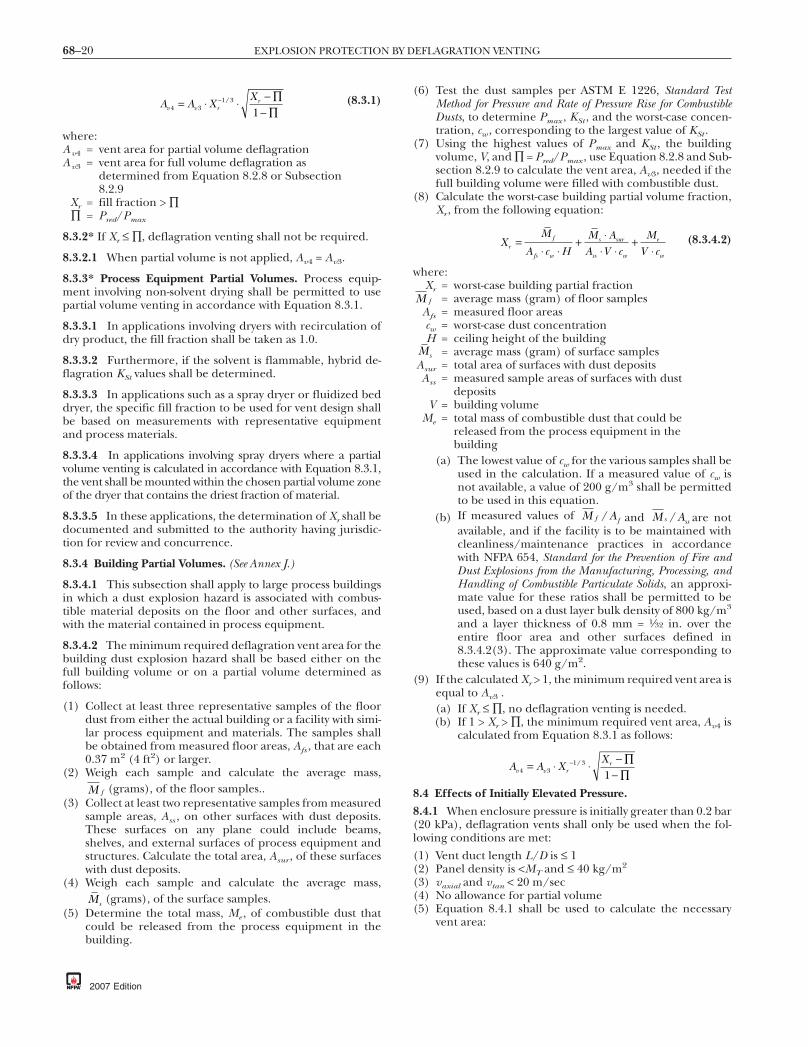
68–20 EXPLOSION PROTECTION BY DEFLAGRATION VENTING
A A XX
v v rr
4 31 3
1= ∏
∏−⋅ ⋅ −
−/ (8.3.1)
where:Av4 = vent area for partial volume deflagrationAv3 = vent area for full volume deflagration as
determined from Equation 8.2.8 or Subsection8.2.9
Xr = fill fraction > ∏∏ = Pred/Pmax
8.3.2* If Xr ≤ ∏, deflagration venting shall not be required.
8.3.2.1 When partial volume is not applied, Av4 = Av3.
8.3.3* Process Equipment Partial Volumes. Process equip-ment involving non-solvent drying shall be permitted to usepartial volume venting in accordance with Equation 8.3.1.
8.3.3.1 In applications involving dryers with recirculation ofdry product, the fill fraction shall be taken as 1.0.
8.3.3.2 Furthermore, if the solvent is flammable, hybrid de-flagration KSt values shall be determined.
8.3.3.3 In applications such as a spray dryer or fluidized beddryer, the specific fill fraction to be used for vent design shallbe based on measurements with representative equipmentand process materials.
8.3.3.4 In applications involving spray dryers where a partialvolume venting is calculated in accordance with Equation 8.3.1,the vent shall be mounted within the chosen partial volume zoneof the dryer that contains the driest fraction of material.
8.3.3.5 In these applications, the determination of Xr shall bedocumented and submitted to the authority having jurisdic-tion for review and concurrence.
8.3.4 Building Partial Volumes. (See Annex J.)
8.3.4.1 This subsection shall apply to large process buildingsin which a dust explosion hazard is associated with combus-tible material deposits on the floor and other surfaces, andwith the material contained in process equipment.
8.3.4.2 The minimum required deflagration vent area for thebuilding dust explosion hazard shall be based either on thefull building volume or on a partial volume determined asfollows:
(1) Collect at least three representative samples of the floordust from either the actual building or a facility with simi-lar process equipment and materials. The samples shallbe obtained from measured floor areas, Afs , that are each0.37 m2 (4 ft2) or larger.
(2) Weigh each sample and calculate the average mass,M f (grams), of the floor samples..
(3) Collect at least two representative samples from measuredsample areas, Ass , on other surfaces with dust deposits.These surfaces on any plane could include beams,shelves, and external surfaces of process equipment andstructures. Calculate the total area, Asur , of these surfaceswith dust deposits.
(4) Weigh each sample and calculate the average mass,Ms (grams), of the surface samples.
(5) Determine the total mass, Me , of combustible dust thatcould be released from the process equipment in thebuilding.
2007 Edition
(6) Test the dust samples per ASTM E 1226, Standard TestMethod for Pressure and Rate of Pressure Rise for CombustibleDusts, to determine Pmax , KSt , and the worst-case concen-tration, cw , corresponding to the largest value of KSt .
(7) Using the highest values of Pmax and KSt , the buildingvolume, V, and ∏ = Pred/Pmax , use Equation 8.2.8 and Sub-section 8.2.9 to calculate the vent area, Av3, needed if thefull building volume were filled with combustible dust.
(8) Calculate the worst-case building partial volume fraction,Xr , from the following equation:
XM
A c HM AA V c
MV cr
f
fs w
s sur
ss w
e
w
=⋅ ⋅
+ ⋅⋅ ⋅
+⋅
(8.3.4.2)
where:Xr = worst-case building partial fraction
M f = average mass (gram) of floor samplesAfs = measured floor areascw = worst-case dust concentrationH = ceiling height of the building
Ms = average mass (gram) of surface samplesAsur = total area of surfaces with dust depositsAss = measured sample areas of surfaces with dust
depositsV = building volume
Me = total mass of combustible dust that could bereleased from the process equipment in thebuilding
(a) The lowest value of cw for the various samples shall beused in the calculation. If a measured value of cw isnot available, a value of 200 g/m3 shall be permittedto be used in this equation.
(b) If measured values of M Af f/ and M As ss/ are notavailable, and if the facility is to be maintained withcleanliness/maintenance practices in accordancewith NFPA 654, Standard for the Prevention of Fire andDust Explosions from the Manufacturing, Processing, andHandling of Combustible Particulate Solids, an approxi-mate value for these ratios shall be permitted to beused, based on a dust layer bulk density of 800 kg/m3
and a layer thickness of 0.8 mm = 1⁄32 in. over theentire floor area and other surfaces defined in8.3.4.2(3). The approximate value corresponding tothese values is 640 g/m2.
(9) If the calculated Xr > 1, the minimum required vent area isequal to Av3 .(a) If Xr ≤ ∏, no deflagration venting is needed.(b) If 1 > Xr > ∏, the minimum required vent area, Av4 is
calculated from Equation 8.3.1 as follows:
A A XX
v v rr
4 31 3
1= ∏
∏−⋅ ⋅ −
−/
8.4 Effects of Initially Elevated Pressure.
8.4.1 When enclosure pressure is initially greater than 0.2 bar(20 kPa), deflagration vents shall only be used when the fol-lowing conditions are met:
(1) Vent duct length L/D is ≤ 1(2) Panel density is <MT and ≤ 40 kg/m2
(3) vaxial and vtan < 20 m/sec(4) No allowance for partial volume(5) Equation 8.4.1 shall be used to calculate the necessary
vent area:

68–21VENTING OF DEFLAGRATIONS OF DUSTS AND HYBRID MIXTURES
AAA
P PPvep
v
v
stat initial
effective
= ⋅ ⋅ + ⋅ −+
−1
0
410 1 1 541
.⎛
⎝⎜⎜
⎞
⎠⎟⎟
44 3
3 4 11
/
/
⎡
⎣⎢⎢
⎤
⎦⎥⎥
∏
⋅
⋅ ⋅ −
K
V
St
effective
(8.4.1)
where:Avep = vent area (m2)Pstat = static burst pressure of the vent (bar)
Pinitial = enclosure pressure at the moment of ignition(bar)
Peffective = 1/3 Pinitial (bar)KSt = deflagration index (determined at initially
atmospheric pressure) (bar-m/sec)V = enclosure volume (m3)
Πeffective = (Pred − Peffective)/(P Emax − Peffective)
Pred = reduced pressurePE
max = [(Pmax + 1) · (Pinitial + 1)/(1 bar-abs)−1]maximum pressure of the unventeddeflagration at initially elevated pressure (bar)
Pmax = maximum pressure of an unvented deflagrationinitially at atmospheric pressure (bar)
8.4.2 An enclosure shall be permitted to be protected withinitially elevated pressure with deflagration vents when thevents are designed according to full-scale test data.
8.5* Effects of Vent Ducts.
8.5.1 If there is no vent duct, Avf = Av 4; otherwise the effect ofvent ducts shall be calculated from the following equation.This solution is iterative, as E1 and E2 are both functions of Avf.
A A E EKKvf v= ( )4 1
0 820 4
0
1 1 18⋅ + ⋅ ⋅ ⋅. . . (8.5.1a)
where:Avf = vent area required when a duct is attached to the
vent opening (m2)Av4 = vent area after adjustment for partial volume
(m2), per Equation 8.3.1
EA L
Vvf duct
1 =⋅ (8.5.1b)
EA
P K Vvf
stat St2
4
4 3 3 4
10
1 1 54= ( )
⋅+ ⋅ ⋅ ⋅. / /
(8.5.1c)
where:Pstat = nominal static opening pressure of the vent
cover (bar)V = enclosure volume (m3)
Lduct = vent duct overall length (m)K0 = 1.5, the resistance coefficient value assumed for
the test configurations that generated the dataused to validate Equations 8.2.2 and 8.2.3
KP
UK
f LD
K KinletD
helbows outlet≡ ∆ =
12
2⋅ ⋅+ ⋅ + + + …
ρ(8.5.1d)
where:K = overall resistance coefficient of the vent duct
applicationKinlet,
Kelbows,Koutlet
= resistance coefficients for fittings
U = fluid velocityDh = vent duct hydraulic diameter (m)fD = D’Arcy friction factor for fully turbulent flow;
see A.8.5 for typical formula [115]
8.5.2 Under certain circumstances, there can be two solu-tions for vent area. In these cases, the smaller vent area shallbe used.
8.5.3 Where these equations do not produce a solution forvent area, the design shall be modified by decreasing the ventduct length or strengthening the vessel to contain a higher Predor both.
8.5.4 Equation 8.5.1a shall not be used if the vent cover is notlocated at the entrance of the duct.
8.5.5 Equation 8.5.1a shall not be used if the initial pressureexceeds plus or minus 0.2 bar-g.
8.5.6 Equation 8.5.1a shall not be used if the vent duct cross-sectional area varies by more than 10 percent anywhere alongthe length.
8.5.7 It shall be permissible to use Equation 8.5.1a for ventducts equipped with elbows, bird-screens, and rain-covers aslong as these obstructions are properly accounted for throughthe duct resistance coefficient K.
8.5.8 It shall be permitted to use vent ducts outside the limi-tations of Equation 8.5.1a when designed in accordance withfull-scale test data.
8.5.9 The maximum length of the duct shall be limited toobey the following inequality:
LD
K KeffSt St
≤⎡
⎣⎢
⎤
⎦⎥ min
10 000 11 000,,
,⋅ (8.5.9)
where:min(A, B) = minimum value of either A or B
Leff = min(Lduct , Ldusty)Ldusty = (Pmax – Pred) · V/Av
8.5.10 Table 8.5.10 shall be reviewed to determine the com-bination rules and limitations for application of various dustmodels in this chapter.
8.6 Bins, Hoppers, and Silos.
8.6.1 Deflagration venting for bins, hoppers, and silos shallbe from the top or the upper side, above the maximum level ofthe material contained, and shall be directed to a safe outsidelocation (see Section 8.8).
8.6.1.1* Deflagration venting shall be permitted to be throughvent closures located in the roof or sidewall, or by making theentire enclosure top a vent.
8.6.1.2 In all cases, the total volume of the enclosure shall beassumed to contain a suspension of the combustible dust inquestion.
2007 Edition
drodriguez
Resaltado

68–22 EXPLOSION PROTECTION BY DEFLAGRATION VENTING
8.6.1.3 No credit shall be taken for the enclosure being partlyfull of settled material.
8.6.1.4 For a multiple application, the closures shall beplaced symmetrically to minimize the effects of potential reac-tion forces (see 6.3.5).
8.6.1.5 Care shall be taken not to fill the enclosure above thebottoms of the vent panels, as large amounts of dust can blowout into the atmosphere, ignite, and form a large fireball.
8.6.2 Deflagration venting shall be permitted to be accom-plished by means of vent closures located in the roof of theenclosure.
8.6.2.1 The vent operation procedures outlined in Section6.5 shall be followed.
8.6.3* The entire enclosure top shall be permitted to be usedto vent deflagrations.
8.6.3.1 Roof panels shall be as lightweight as possible andshall not be attached to internal roof supports.
8.6.3.2 API 650, Welded Steel Tanks for Oil Storage, shall be ref-erenced for guidelines for the design of a frangible, weldedroof joint.
8.6.3.3 Equipment, piping, and other attachments shall notbe connected to the roof directly, as they could restrict theroof’s operation as a vent closure.
8.6.3.4 The remaining portions of the enclosure, includinganchoring, shall be designed to resist the calculated Pred ,based on the vent area provided. (See Section 6.3.)
Table 8.5.10 Combination Rules and Limitations forNFPA 68 Dust Models
Model Application
Vent ducts 0.8 ≤ P0 ≤ 1.2 bar-absPanel density ≤ MT and ≤ 40 kg/m2
Allow partial volume1≤ L/D ≤ 6(calculate vent duct effect last)
Partial volume Allow vent ductPanel density ≤ 40 kg/m2
0.8 ≤ P0 ≤ 1.2 bar-abs1 ≤ L/D ≤ 6(calculate vent duct effect last)
Elevated initialpressure
No vent ductPanel density ≤ MT and ≤ 40 kg/m2
0.2 ≤ P0 ≤ 4 bar-gFull volume deflagration1 ≤ L/D ≤ 6(calculate elevated initial pressureeffect last)
Panel inertia 0.8 ≤ P0 ≤ 1.2 bar-aNo vent ductPanel density ≤ 40 kg/m2
Allow partial volume1 ≤ L/D ≤ 6
2007 Edition
8.7 Venting of Dust Collectors Using Bags, Filters, or Cartridges.
8.7.1 The following three venting alternatives shall be per-mitted:
(1) Locate all of the venting area below the bottom of thebags, filters, or cartridges, as shown in Figure 8.7.1(a) andFigure 8.7.1(b).(a) When the spacing between bags is less than or equal
to the radius of the bag, filter, or cartridge, the ventarea shall be permitted to be calculated on the basisof the volume below the lower end of the bags.
(b) When the spacing between bags is greater than theradius of the bag, filter, or cartridge, the vent areashall be permitted to be calculated on the basis of thedirty side only; that is, calculate the volume below thetube sheet, and subtract out the volume occupied bythe bags.
(2) Locate the vents as shown in Figure 8.7.1(c) and Figure8.7.1(d), and bags are either completely removed orshortened so that they do not extend below the top of thevent for a distance of one vent diameter from the vent. Inaddition, the bags immediately adjacent to the vent shall beremoved and the remaining bags shall be restrained frompassing through the vent. For this case, the vent area shall bepermitted to be calculated on the basis of the dirty side only;that is, calculate the volume below the tube sheet, and sub-tract out the volume occupied by the bags.
(3) Locate the vents such that the bottom of the vent(s) is ator above the bottom of the bags, as shown in Figure8.7.1(e), and the row of bags closest to the vent are re-strained from passing through the vent. For this case, thevolume used to calculate the vent area shall be the entirevolume (clean and dirty) below the tube sheet.
8.7.2 A key assumption made for the three alternatives in8.7.1 is that the clean air plenum above the tube sheet shall beessentially free of dust accumulations.
8.7.3 If the clean air plenum contains dust, a separate vent onthe clean air side shall be calculated based on the clean airside volume.
FIGURE 8.7.1(a) Venting of Dust Collectors — AlternativeArrangement 1.

68–23VENTING OF DEFLAGRATIONS OF DUSTS AND HYBRID MIXTURES
8.8* Fireball Dimensions. Measures shall be taken to reducethe risk to personnel and equipment from the effects of fire-ball temperature and pressure.
8.8.1 A documented risk assessment shall be permitted to beused to reduce the hazard distances calculated in 8.8.2 and8.8.3.
8.8.2* In the case of dust deflagration venting, the distance, D,shall be expressed by Equation 8.8.2:
D KVn
= ⎛⎝⎜
⎞⎠⎟
⋅1 3/
(8.8.2)
where:D = axial distance (front) from the vent (m)K = flame length factorK = 10 for metal dusts, K = 8 for chemical and
agricultural dustsV = volume of vented enclosure (m3)n = number of evenly distributed vents
SS
Spacing, S
Radius, r
S
S ≤ r, See 8.7.1(1)(a).
S > r, See 8.7.1(1)(b).
FIGURE 8.7.1(b) Plan View of Bag Spacing for Figure8.7.1(a).
FIGURE 8.7.1(c) Venting of Dust Collectors — AlternativeArrangement 2.
8.8.2.1 Axial distance, calculated by Equation 8.8.2, shall belimited to 60 m. [104]
8.8.2.2 The width of the projected flame measured from thecenterline of the vent shall be calculated as one-half D.
8.8.2.3 The height of the fireball shall be defined to be thesame dimension D, with half the height located below the cen-ter of the vent and half the height located above.
8.8.3* Where venting is from a cubic vessel, Pmax,a value shallbe indicated approximately by Equation 8.8.3 [108]:
P P A Va red vmax,. ..= 0 2 0 1 0 18⋅ ⋅ ⋅ (8.8.3)
where:Pmax,a = external pressure (bar)
Pred = reduced pressure (bar)Av = vent area (m2)V = enclosure volume (m3)
D
D
Vent diameter, D
Bag restraint forfull length bags
Full length bag
Shortened or removed bag
FIGURE 8.7.1(d) Plan View of Bag Spacing for Figure8.7.1(c).
FIGURE 8.7.1(e) Venting of Dust Collectors — AlternativeArrangement 3.
2007 Edition

68–24 EXPLOSION PROTECTION BY DEFLAGRATION VENTING
8.8.4 For longer distances, r (in meters), the maximum exter-nal pressure, Pmax,r , shall be indicated approximately by Equa-tion 8.8.4:
P PD
rr amax, max,
.= ⎛⎝⎜
⎞⎠⎟
0 20 ⋅ (8.8.4)
where:Pmax,r = maximum external pressurePmax,a = external pressure (bar)
D = maximum length of fireball (m)r = distance from vent ≥0.2 D(m)
8.8.5 Equations 8.8.2, 8.8.3, and 8.8.4 shall be valid for thefollowing conditions:
(1) Enclosure volume: 0.3 m3 ≤ V ≤ 10,000 m3
(2) Reduced pressure: Pred ≤ 1 bar(3) Static activation pressure: Pstat ≤ 0.1 bar(4) Deflagration index: KSt ≤ 200 bar-m/sec(5) Pmax ≤ 9 bar
8.9* Venting Internal to a Building with Flame-Arresting andParticulate-Retention Device.
8.9.1 Expected overpressure shall be compared to the build-ing design, and building venting shall be considered to limitoverpressures.
8.9.2 The resulting pressure increase in an unvented build-ing shall be permitted to be estimated from the following:
(1) ∆P = 1.74 P0 (V1/V0)(2) V0 = free volume of building(3) V1 = volume of protected equipment(4) P0 = ambient pressure (14.7 psia or 1.013 bar abs)(5) ∆P = pressure rise in the building (in same units as P0)
8.9.3 It shall be permitted to use a lower value of the coeffi-cient shown in the equation in 8.9.2(1) where experimentaldata are available to substantiate the lower value.
8.10* Deflagration Venting of Enclosures Interconnected withPipelines.
8.10.1* For interconnecting pipelines with inside diametersno greater than 0.3 m (1 ft) and lengths no greater than 6 m(20 ft), the following requirements shall apply [104]:
(1) The venting device for the enclosure shall be designed fora Pstat < 0.2 bar.
(2) Enclosures of volumes within 10 percent of each othershall be vented as determined by Equations 8.2.2 and8.2.3.
(3) If enclosures have volumes that differ by more than10 percent, the vents for both enclosures shall be de-signed as if Pred were equal to 1 bar or less. The enclosureshall be designed with Pes equal to a minimum of 2 bar.
(4) If it is not possible to vent the enclosure with the smallervolume in accordance with this standard, the smaller en-closure shall be designed for the maximum deflagrationpressure, Pmax , and the vent area of the larger enclosurewith the larger volume shall be doubled.
(5) The larger enclosure shall be vented or otherwise pro-tected as described in NFPA 69, Standard on Explosion Pre-vention Systems, in order for the deflagration venting ofsmaller enclosures to be effective.
2007 Edition
Chapter 9 Venting of Deflagrations of Gasesand Dusts in Pipes and Ducts Operating
at or Near Atmospheric Pressure
9.1* Introduction.
9.1.1 This chapter shall apply to systems handling gases ordusts operating at pressures up to 0.2 bar (3 psi).
9.1.2 This chapter shall apply to pipes, ducts, and elongatedvessels with length-to-diameter ratios of 5 or greater for gases,and 6 or greater for dusts.
9.1.3 This chapter shall not apply to vent discharge ducts.
9.1.4 This chapter shall not apply to oxidants other than airor to mixtures at elevated initial temperatures that are greaterthan 57°C (134°F).
9.2* Design.
9.2.1 Each vent location along a pipe, duct, or elongated vesselshall have a vent area equal to the total cross-sectional area ateach vent location.
9.2.2 The vent area needed at a vent location shall be permit-ted to be accomplished by using one, or more than one, ventat each location.
9.2.3 For noncircular cross sections, the diameter shall be thehydraulic diameter that is equal to 4 (A/p), where A is thecross-sectional area and p is the perimeter of the cross section.
9.2.4* Pipes or ducts connected to a vessel in which a deflagra-tion can occur shall have a vent located on the pipe or duct ata location no more than two pipe or duct diameters from thepoint of connection to the vessel.
9.2.5 For systems that handle gases, vents shall be providedon each side of turbulence-producing devices at a distance ofno more than three diameters of the pipe or duct.
9.2.6 The weight of deflagration vent closures shall not ex-ceed 12.2 kg/m2 (2.5 lb/ft2) of free vent area.
9.2.7 Deflagration vents shall discharge to a location that can-not endanger personnel.
9.2.8 The static burst pressure of the vent closures shall beless than 0.3 bar (4 psi).
9.2.9 Transition to Detonation.
9.2.9.1 Vents shall be placed on pipes and ducts to prevent adeflagration from transitioning into a detonation.
9.2.9.2* If L/D ratios are greater than those shown in Figure9.2.10.1, multiple vents shall be installed in accordance withSection 9.3.
9.2.10 Use of a Single Deflagration Vent on a Pipe or Duct.
9.2.10.1* Figure 9.2.10.1 shall be used to determine the maxi-mum allowable length of a smooth, straight pipe, duct, or ves-sel that is closed on one end and vented on the other where noadditional deflagration vents are required.
9.2.10.2 The maximum pressure during deflagration vent-ing, Pred , in a pipe or duct shall be no greater than 50 percentof the yield strength of the pipe or duct.
drodriguez
Resaltado
drodriguez
Resaltado

68–25VENTING OF DELFAGRATIONS IN PIPES AND DUCTS OPERATING AT OR NEAR ATMOSPHERIC PRESSURE
9.2.10.2.1 Flammable Gas Systems with a Flow Velocity of2 m/sec or Less.
9.2.10.2.1.1 The maximum pressure during deflagration vent-ing, Pred , in a pipe or duct that conveys propane or gases that havea fundamental burning velocity of less than 60 cm/sec shall bedetermined from Figure 9.2.10.2.1.1.
9.2.10.2.1.2 For other pipe diameters, Pred shall be deter-mined by interpolation using Figure 9.2.10.2.1.1.
9.2.10.2.2 Dust Systems with a Flow Velocity of 2 m/sec orLess.
9.2.10.2.2.1* The maximum pressure during deflagrationventing, Pred , in a pipe or duct that conveys dusts shall be esti-mated from Figure 9.2.10.2.2.1.
9.2.10.2.2.2 For dusts having other values of KSt , Pred shall bedetermined by interpolation.
9.2.11 For system flow velocities greater than 2 m/sec and forgases with fundamental burning velocities greater than60 cm/sec (2 ft/sec), additional vent area shall be provided inaccordance with Section 9.3.
(L/D
) max
0D (m)
4
120
0
60
40
20
1 2 3
80
100
Dusts with KSt ≤ 200
Propane, dusts with KSt > 200
L = Distance between deflagration ventsor
Length of pipe or duct having one end open
FIGURE 9.2.10.1 Maximum Allowable Distance, Expressedas Length-to-Diameter Ratio, for a Smooth, Straight Pipe orDuct.
Pre
d (b
ar)
0 80
10
5
04020 60
D = 1.6 mD = 0.4 m
D = 0.2 m
L/D
FIGURE 9.2.10.2.1.1 Maximum Pressure Developed DuringDeflagration of Propane/Air Mixtures Flowing at 2 m/sec orLess in a Smooth, Straight Pipe Closed at One End.
9.2.12 For systems having an initial flow velocity greater than20 m/sec, for gases having a burning velocity more than 1.3times that of propane, or for dusts with KSt> 300, vent place-ment shall be determined by tests.
9.3* Multiple Deflagration Vents on a Pipe or Duct.
9.3.1 Figure 9.3.1 shall be used to determine the maximumdistance between each vent for a maximum pressure duringdeflagration venting of 0.17 bar (2.5 psi).
9.3.1.1 Figure 9.3.1 shall apply to system flow velocities up to20 m/sec (66 ft/sec).
9.3.1.2 Figure 9.3.1 shall also apply to dusts with a KSt lessthan or equal to 300 bar-m/sec and to propane.
9.3.2 For gases other than propane, the maximum pressureduring deflagration and the distances between vents shall be cal-culated using Equations 9.3.2a and 9.3.2b, which are limited tofundamental burning velocities below 60 cm/sec (2 ft/sec):
Pre
d (b
ar)
0 80
10
5
04020 60 100
KSt = 300
KSt = 200
KSt = 100
L/D
FIGURE 9.2.10.2.2.1 Maximum Pressure Developed DuringDeflagration of Dust/Air Mixtures Flowing at 2 m/sec or Lessin a Smooth, Straight Pipe Closed at One End.
0D (m)
15
5
0 21
10
Propane and dusts with KSt ≤ 300initial velocity between2 m/sec and 20 m/sec
L/D
FIGURE 9.3.1 Vent Spacing Needed to Keep Pred from Ex-ceeding 0.17 bar for Propane and Dusts with a KSt Less Than300 bar-m/sec.
2007 Edition

68–26 EXPLOSION PROTECTION BY DEFLAGRATION VENTING
P PS
Sred x red pu x
u p, ,
,
,
=⎛
⎝⎜⎜
⎞
⎠⎟⎟⋅
2
(9.3.2a)
L LS
Sx pu p
u x
=⎛
⎝⎜⎜
⎞
⎠⎟⎟⋅ ,
,
2
(9.3.2b)
where:Pred,x = maximum pressure predicted for gas [bar (psi)]Pred,p = 0.17 bar (2.5 psi)— maximum pressure for
propaneLx = distance between vents for gas [m (ft)]Lp = distance between vents for propane [m (ft)]
Su,x = fundamental burning velocity of gasSu,p = fundamental burning velocity of propane
Chapter 10 Details of DeflagrationVents and Vent Closures
10.1* Normally Open Vents.
10.1.1 Louvered Openings.
10.1.1.1 Increases in Pred due to louvered openings shall beaccounted for in a documented system design.
10.1.1.2 The pressure drop through the louvered vent shall bedetermined by gas flow calculations, and Pred shall be adjusted.
10.1.2 Hangar-Type Doors. Large hangar-type or overheaddoors shall be permitted to be installed in the walls of roomsor buildings that contain a deflagration hazard.
10.1.2.1 The doors shall be permitted to be opened to pro-vide sizable unobstructed vents during the operation of a pro-cess or of equipment in which there is an inherent deflagra-tion hazard.
10.1.2.2 The opening shall be considered to be a vent onlywhen the door is not in place.
10.1.2.3 Interlocks with process systems that create a defla-gration hazard shall be provided to ensure that the doors areopen when the process is in operation.
10.2 Normally Closed Vents.
10.2.1 The vent closure manufacturer or designer shall beresponsible for documenting the value and tolerance of thePstat of a vent closure where installed according to the manu-facturer’s recommendation in the intended application.
10.2.2 Testing shall be carried out to establish the Pstat for anyclosure release mechanism, with the mechanism installed onthe vent closure and tested as a complete assembly.
10.2.2.1 The requirement in 10.2.2 shall apply to all types ofclosure mechanisms, including pull-through fasteners; shearbolts; spring-loaded, magnetic, and friction latches; and rup-ture diaphragms.
10.2.2.2 For field-fabricated vent closures, the designer shalldocument that the entire assembly releases at the Pstat specified.
10.2.2.2.1 The documentation shall include the design Pred ,Pstat , enclosure surface area, closure area, panel mass per unitarea, types of fasteners, spacing, and quantity.
2007 Edition
10.2.2.2.2 The design records and installation drawings shallbe maintained by the building owner and operator.
10.2.2.3 Where vent closure mechanisms or fasteners areused, they shall be listed for the application.
10.2.3 The vent closure shall be designed to release at thecalculated pressure and shall be compatible with the serviceconditions to which it is to be exposed.
10.2.3.1 Vent closures shall be designed for their expectedtemperature range.
10.2.4 The closure shall be designed to withstand naturalforces such as wind or snow loads, operating conditions suchas internal pressure fluctuations and internal temperature,and the effects of corrosion.
10.3 Types of Building or Room Vent Closures. The followingtypes of vent closures shall be permitted to be used with low-strength enclosures such as those covered by Chapter 7.
10.3.1 Hinged Doors, Windows, and Panel Closures. Hingeddoors, windows, and panel closures shall be designed to swingoutward and have latches or similar hardware that automati-cally release under the calculated release pressure.
10.3.1.1 Friction, spring-loaded, or magnetic latches of thetype used for doors on industrial ovens shall be permitted tobe used.
10.3.1.2 For personnel safety, the door or panel shall be de-signed to remain intact and to stay attached.
10.3.1.3 Materials that tend to fragment and act as shrapnelshall not be used.
10.3.2* Shear and Pull-Through Fasteners. Listed shear andpull-through fasteners shall be permitted to be used where thevent design calls for large vent areas, such as the entire wall ofa room.
10.3.2.1 At locations where personnel or equipment can bestruck by flying vent closures, tethering of the vent closure orother safety measures shall be required.
10.3.2.2* Where restraint is required, any vent restraint designshall be documented by the designer.
10.3.2.3 No restraint for any vent closure shall result in re-stricting the required vent area or slowing the response timeof the closure.
10.3.2.4 Any hardware added to a vent closure shall be in-cluded when determining the total mass of the closure, sub-ject to Section 6.7.
10.4* Restraints for Large Panels. Any vent restraint designshall be documented by the designer.
10.4.1 No restraint for any vent closure shall result in restrict-ing the vent area.
10.4.2 Any hardware added to a vent closure shall be in-cluded when determining the total mass of the closure, sub-ject to Section 6.7.
10.5 Equipment Vent Closures.
10.5.1* Hinged Devices. Hinged doors or covers shall be per-mitted to be designed to function as vent closures.
10.5.1.1* The hinge shall be designed to ensure that the clo-sure device remains intact during venting.

68–27INSPECTION AND MAINTENANCE
10.5.1.2* Hinged devices shall be permitted to be used on totallyenclosed mixers, blenders, dryers, and similar equipment.
10.5.1.3 Charging doors or inspection ports shall be permit-ted to be designed to serve this purpose where their actiondoes not endanger personnel.
10.5.1.4 Regular maintenance of hinge and spring-loadedmechanisms shall be performed to ensure proper operation.
10.5.1.5 If a hinged vent closure is followed by a vent duct,special consideration shall be given to the clearance betweenthe front edge of the closure panel and the duct wall through-out the course of the opening arc.
10.5.1.5.1 The clearance shall not hinder flow during theventing while the vent closure is swinging open.
10.5.1.5.2 The amount of clearance needed from the frontedge of the hinged closure, in the closed position, to the wallof the vent duct shall be approximately half the length of thehinged closure from the hinge to the front edge.
10.5.1.6* Vacuum breakers shall be permitted to be designedaccording to Figure 10.5.1.6 and installed to prevent inward de-formation, provided they either are built strongly enough towithstand the Pred during venting or open to leave a clear path.
10.5.2* Rupture Diaphragm Devices. Only rupture diaphragmswith controlled opening patterns that ensure full opening oninitial rupture shall be utilized.
Vac
uum
rel
ief (
m2 )
Volume of enclosure (m3)
1000
1.0
0.00110
0.1
0.01
100
Vacuum re
sistance
of vesse
l 25 m
bar
50 mbar
100 mbar
200 mbar
500 mbar
FIGURE 10.5.1.6 Graph to Determine the Vacuum ReliefArea for Vacuum Vents on Enclosures. [104]
10.6* Flame-Arresting and Particulate-Retention Vent Systems.
10.6.1 Flame-arresting and particulate-retention vent systemsshall be listed for their application.
10.6.2 The deflagration venting area provided for the protectedenclosure shall be increased to compensate for the reduction inventing efficiency due to the presence of the device.
10.6.3* The following limitations shall apply:
(1) Where a flame-arresting and particulate-retention vent sys-tem is used inside a building, a documented risk analysisshall be performed to ensure safe installation. Consider-ations shall include, but are not limited to, the following:(a) Proximity of personnel(b) Volume of room(c) Possibility of combustible mixtures exterior to the
equipment(d) Possible toxic emissions
(2) A flame-arresting and particulate-retention vent systemshall be sized to ensure that Pred remains within the enclo-sure design limits.
Chapter 11 Inspection and Maintenance
11.1 General.
11.1.1 This chapter covers the installation, inspection, andmaintenance procedures necessary for proper function andoperation of vent closures for venting deflagrations.
11.1.2 Sections 11.4 through 11.10 shall be applied retroactively.
11.2* Design Parameters and Documentation. Data sheets, in-stallation details, and design calculations shall be developed andmaintained for each vent closure application, suitable for reviewby an authority having jurisdiction that verifies the vent area issufficient to prevent deflagration pressure from exceeding theenclosure strength and identifies areas exposed to potential over-pressure, event propagation, and fireball effects during venting.Documentation shall include all of the following:
(1) Manufacturer’s data sheets and instruction manuals(2) Design calculations(3) General specifications(4) Vent closure specifications(5) End user inspection/maintenance forms(6) User documentation of conformity with applicable
standards(7) Vent closure identification(8) Combustible material properties test report(9) Copy of vent identification label
(10) Process plan view(11) Process elevation view(12) Vent relief (pressure and fireball) path(13) Proximity of personnel to vent relief path(14) Mechanical installation details(15) Electrical supervision (if provided) installation details(16) Vent restraint installation and design documentation (if
required)(17) Process interlocks (if provided)(18) Event deflagration isolation requirements (if required)(19) Employee training requirements
11.3 Installation.
11.3.1 Mounting frames shall be fabricated and mounted sothat the vent closure is not stressed in any way that will contrib-ute to fatiguing the vent closure.
2007 Edition

68–28 EXPLOSION PROTECTION BY DEFLAGRATION VENTING
11.3.2 Vent closures shall be installed per manufacturer’s re-quirements.
11.3.3 The final installation shall be inspected to verify itsconformance to the design.
11.3.4* Vent closure shall be clearly marked.
WARNING: Explosion relief device.
11.4* Inspection.
11.4.1 Vent closures shall be inspected according to 11.4.4 atleast annually.
11.4.2* The frequency of the inspection described in 11.4.4shall be permitted to be increased or decreased based ondocumented operating experience.
11.4.3 The owner/operator of the facility in which the defla-gration vent closures are located shall be responsible for in-specting and maintaining such devices after they are installed.
11.4.4 The inspector shall verify, as applicable, that the ventinspection determines the following:
(1) The opening is free and clear of any obstructions onboth sides.
(2) The discharged material and fireball pathway does notextend into an area normally occupied by personnel orcritical process equipment.
(3) The closure has been properly installed according tomanufacturer’s instructions.
(4) The closure is not corroded or mechanically damaged.(5) The closure is clearly identified with manufacturer’s in-
formation.(6) The closure is clearly labeled as an explosion relief device.(7) The closure has no damage and is protected from the
accumulation of water, snow, ice, or debris after any actof nature.
(8) The closure has not been painted or coated other thanby manufacturer.
(9) The closure has no buildup of deposits on the insidesurfaces or between layers of the vent.
(10) The closure has not been tampered with.(11) The closure shows no fatigue and has not released.(12) The closure hinges (if provided) are lubricated and op-
erate freely.(13) The closure restraints (if provided) are in place and op-
erational.(14) The closure seals, tamper indicators, or vent rupture in-
dicators (e.g., breakwire switches), if provided, are inplace.
(15) The flame-arresting and particulate-retention device isbeing maintained, is clean, and is unobstructed in accor-dance with the manufacturer’s listing.
(16) The closure has no conditions that would hinder itsoperation.
11.4.5 The owner/operator shall verify by signature on theinspection form that the production process material has notchanged since the last inspection.
11.5* Vent Closure Design Parameters. The vent closure de-sign parameters shall be maintained and made available formanagement of change review, employee training informa-tion, inspection, and re-ordering purposes.
11.6 Inspection Reports. Deficiencies found during inspec-tions shall be reported to the owner/operator.
2007 Edition
11.7 Record Keeping.
11.7.1 A record shall be maintained that indicates the dateand the results of each inspection and the date and descrip-tion of each maintenance activity.
11.7.2 The records of inspections shall be retained for a mini-mum of 3 years.
11.8 Management of Change. Management shall implementand maintain written procedures to evaluate proposedchanges to facility and processes, both physical and human,for the impact on safety, loss prevention, and control.
11.8.1 Management of change procedures shall be followedfor any change to process, materials, technology, equipment,process flow, exposure, or procedures affecting equipmentprotected by requirements in this document.
11.8.2* Management of change documentation shall be avail-able for review by the relevant authority having jurisdiction.
11.8.3 The management of change procedures shall ensurethat the following issues are addressed prior to any change:
(1) The technical basis for the proposed change(2) The safety and health implications(3) Review of fire and explosion prevention systems(4) Whether the change is permanent or temporary(5) Personnel exposure changes(6) Modifications to operating maintenance procedures(7) Employee training requirements(8) Authorization requirements for the proposed change
11.8.4 Implementation of the management of change proce-dures shall not be required for replacements-in-kind.
11.8.5 Design documentation as required by Chapter 11 shallbe updated to incorporate the change.
11.9 Maintenance.
11.9.1 Vent closure maintenance shall be performed after ev-ery act of nature or process upset condition to ensure that theclosure has not been physically damaged and there are noobstructions including but not limited to snow, ice, water,mud, or process material that could lessen or impair the effi-ciency of the vent closure.
11.9.2 An inspection shall be performed in accordance with11.4.4 after every process maintenance turnaround.
11.9.3 If process material has a tendency to adhere to thevent closure, the vent closure shall be cleaned periodically tomaintain vent efficiency.
11.9.4 Process interlocks, if provided, shall be verified.
11.9.5 Known potential ignition sources shall be inspectedand maintained.
11.9.6 Records shall be kept of any maintenance and repairsperformed.
11.10 Employee Training.
11.10.1 Initial and refresher training shall be provided andtraining records maintained for employees who are involvedin operating, maintaining, and supervising facilities that uti-lize devices for venting of deflagrations.
11.10.2 Initial and refresher training shall ensure that all em-ployees are knowledgeable about the following:
(1) Hazards of their workplace

68–29ANNEX A
(2) General orientation, including plant safety rules(3) Process description(4) Equipment operation, safe startup and shutdown, and re-
sponse to upset conditions(5) The necessity for proper functioning of related fire and
explosion protection systems(6) Deflagration vent(s) location, vent relief path, and main-
tenance requirements and practices(7) Housekeeping requirements(8) Emergency response and egress plans
Annex A Explanatory Material
Annex A is not a part of the requirements of this NFPA documentbut is included for informational purposes only. This annex containsexplanatory material, numbered to correspond with the applicable textparagraphs.
A.1.1 A deflagration can result from the ignition of a flam-mable gas, mist, or combustible dust. This standard is a com-panion document to NFPA 69, Standard on Explosion PreventionSystems, which covers explosion prevention measures and canbe used in place of, or in conjunction with, NFPA 68. Thechoice of the most effective and reliable means for explosioncontrol should be based on an evaluation that includes thespecific conditions of the hazard and the objectives of protec-tion. Venting of deflagrations only minimizes the damage thatresults from combustion.
A.1.2 It is important to note that venting does not prevent adeflagration; venting can, however, minimize the destructiveeffects of a deflagration.
A.1.3 Vents act as a system in conjunction with the strength ofthe protected enclosure. However, some lightweight struc-tures, such as damage-limiting buildings, can be considered tobe totally self-relieving and require no specific vents.
The following documents specify under which conditions de-flagration venting (explosion protection measures) is required:
(1) NFPA 30, Flammable and Combustible Liquids Code(2) NFPA 30B, Code for the Manufacture and Storage of Aerosol
Products(3) NFPA 33, Standard for Spray Application Using Flammable or
Combustible Materials(4) NFPA 35, Standard for the Manufacture of Organic Coatings(5) NFPA 52, Vehicular Fuel Systems Code(6) NFPA 61, Standard for the Prevention of Fires and Dust Explo-
sions in Agricultural and Food Processing Facilities(7) NFPA 69, Standard on Explosion Prevention Systems(8) NFPA 432, Code for the Storage of Organic Peroxide Formula-
tions(9) NFPA 484, Standard for Combustible Metals
(10) NFPA 654, Standard for the Prevention of Fire and Dust Explo-sions from the Manufacturing, Processing, and Handling ofCombustible Particulate Solids
A.1.3.2 For further information, see NFPA 30, Flammable andCombustible Liquids Code.
A.3.2.1 Approved. The National Fire Protection Associationdoes not approve, inspect, or certify any installations, proce-dures, equipment, or materials; nor does it approve or evalu-ate testing laboratories. In determining the acceptability of
installations, procedures, equipment, or materials, the author-ity having jurisdiction may base acceptance on compliancewith NFPA or other appropriate standards. In the absence ofsuch standards, said authority may require evidence of properinstallation, procedure, or use. The authority having jurisdic-tion may also refer to the listings or labeling practices of anorganization that is concerned with product evaluations and isthus in a position to determine compliance with appropriatestandards for the current production of listed items.
A.3.2.2 Authority Having Jurisdiction (AHJ). The phrase “au-thority having jurisdiction,” or its acronym AHJ, is used inNFPA documents in a broad manner, since jurisdictions andapproval agencies vary, as do their responsibilities. Where pub-lic safety is primary, the authority having jurisdiction may be afederal, state, local, or other regional department or indi-vidual such as a fire chief; fire marshal; chief of a fire preven-tion bureau, labor department, or health department; build-ing official; electrical inspector; or others having statutoryauthority. For insurance purposes, an insurance inspection de-partment, rating bureau, or other insurance company repre-sentative may be the authority having jurisdiction. In manycircumstances, the property owner or his or her designatedagent assumes the role of the authority having jurisdiction; atgovernment installations, the commanding officer or depart-mental official may be the authority having jurisdiction.
A.3.2.4 Listed. The means for identifying listed equipmentmay vary for each organization concerned with product evalu-ation; some organizations do not recognize equipment aslisted unless it is also labeled. The authority having jurisdic-tion should utilize the system employed by the listing organi-zation to identify a listed product.
A.3.3.8 Enclosure. Examples of enclosures include a room,building, vessel, silo, bin, pipe, or duct.
A.3.3.11 Flame Speed. Flame speed is dependent on turbu-lence, the equipment geometry, and the fundamental burningvelocity.
A.3.3.12.1 Lower Flammable Limit (LFL). LFL is also knownas minimum explosible concentration (MEC). See ASTM E681 (2004), Standard Test Method for Concentration Limits of Flam-mability of Chemicals (Vapors and Gases).
A.3.3.14 Flash Point. See ASTM E 502 (2000), Standard TestMethod for Selection and Use of ASTM Standards for the Determina-tion of Flash Point of Chemicals by Closed Cup Methods, to deter-mine the appropriate test method to use.
A.3.3.15 Friction Factor, fD . D’Arcy friction factor relatingpressure drop in a straight duct to velocity and wetted surfacearea, dimensionless:
fD PU LDh= ⋅ ∆
⋅ ⋅2
2ρ
where:Dh = hydraulic diameter∆P = pressure loss across the duct
ρ = fluid densityU = fluid velocity (shown here as U to avoid
confusion with volume)L = duct length
2007 Edition

68–30 EXPLOSION PROTECTION BY DEFLAGRATION VENTING
At least two friction factors are in common usage: theD’Arcy friction factor as used in this document and the Fan-ning friction factor. The two forms differ by a factor of 4, asseen here:
fD P
U LFh= ∆⋅⋅ ⋅2 2ρ
, the Fanning friction factor (A.3.3.15a)
fD PU LD
h= ∆22
⋅ ⋅⋅ ⋅ρ
, the D’Arcy friction factor (A.3.3.15b)
f fD F= 4 (A.3.3.15c)
The equivalent velocity head loss for straight duct is ex-pressed as follows:
Kf LD
F
h
= 4 ⋅ ⋅ when using the
Fanning frriction factor
(A.3.3.15d)
Kf LDD
h
= ⋅ when using the
D’Arcy friction ffactor
(A.3.3.15e)
D’Arcy friction factors are presented in Moody diagramsand can be calculated from equations that represent the dia-grams. See NFPA 750, Standard on Water Mist Fire Protection Sys-tems, for a Moody diagram. Similar diagrams are also availableto provide Fanning friction factors. To be sure that the appro-priate diagram is being used, the user should examine thelaminar region. In the laminar region — that is, a low Rey-nolds number — the D’Arcy friction factor equals 64/Re. TheFanning friction factor in the laminar region equals 16/Re.
Colebrook equations model the friction factor using im-plicit equations, which must be solved iteratively. The factor of4 difference can be seen in the following similar equations:
For the Fanning friction factor
14
3 71 255
10f D fF h F
= −⎡
⎣⎢⎢
⎤
⎦⎥⎥
log.
.ε⋅
+Re
(A.3.3.15f)
For the D’Arcy friction factor
12
3 72 51
10f D fD h D
= −⎛
⎝⎜⎜
⎞
⎠⎟⎟log
..ε
⋅+
Re(A.3.3.15g)
where:ε = the absolute roughness
Re = the dimensionless Reynolds numberNote that ε/D is the dimensionless relative roughness.
When applied to venting, the friction factor is evaluated atfully turbulent conditions, meaning a very large Reynoldsnumber. For these conditions, the D’Arcy form of the Cole-brook equation is rearranged and simplified as follows to al-low a direct solution:
12
3 710f DD h
= − ≈( )⎡
⎣⎢
⎤
⎦⎥log
.ε⋅
+ 0
11 14 2 10f DD h
= −⎛
⎝⎜
⎞
⎠⎟. log
ε
2007 Edition
f
D
D
h
=⎛
⎝⎜
⎞
⎠⎟
⎡
⎣⎢
⎤
⎦⎥
⎧
⎨
⎪⎪
⎩
⎪⎪
⎫
⎬
⎪⎪
⎭
⎪⎪
1
1 14 2
2
. − ⋅ log10
ε(A.3.3.15h)
A.3.3.18 Hydraulic Diameter. Hydraulic diameters for circles,squares, and rectangular, triangular, and elliptical shapes aregiven in Darby (p. 199), Table 7-1.
For circular cross sections, the effective diameter is thestandard diameter. For cross sections other than those that arecircular, the effective diameter is the hydraulic diameter deter-mined by Equation A.3.3.18a, where A is the cross-sectionalarea normal to the longitudinal axis of the space and p is theperimeter of the cross section.
DAph =
⎛
⎝⎜
⎞
⎠⎟4 ⋅ (A.3.3.18a)
The term equivalent diameter, DE , appears in earlier editions ofNFPA 68, but based upon the Committee’s review of the data,which is based on circular ducts, the use of hydraulic diameterwas determined to be more appropriate and has been intro-duced into this edition of the standard. The definition of equiva-lent diameter is shown by the following equation:
DA
E = 2π
(A.3.3.18b)
Equivalent diameters are not the same as hydraulic diameters.
A.3.3.19 KG . See B.1.2.3.
A.3.3.20 KSt . See B.1.2.3.
A.3.3.23 Minimum Ignition Energy (MIE). The lowest value ofthe minimum ignition energy is found at a certain optimummixture. The lowest value, at the optimum mixture, is usuallyquoted as the minimum ignition energy.
A.3.3.25.1 Hybrid Mixture. In certain processes, flammablegases can desorb from solid materials. If the solid is combustibleand is dispersed in the gas–oxidant mixture, as can be the case ina fluidized bed dryer, a hybrid mixture can also result. (See 6.2.3.)
A.3.3.25.2 Optimum Mixture. The optimum mixture is not al-ways the same for each combustion property that is measured.
A.3.3.26 Oxidant. Oxygen in air is the most common oxidant.
A.3.3.28.1 Maximum Rate of Pressure Rise [(dP/dt)max]. SeeAnnex B.
A.4.2.1.1 The nature of a deflagration event is such that per-sonnel in an enclosure where a deflagration occurs do nothave time to exit to a place of safety. Personnel in the space willbe subject to flame and pressure effects. General safety guide-lines of other standards should be consulted for advice on howto prevent hazardous atmospheres or restrict access.
A.4.2.2.2 Treatment of interconnected enclosures needs tobe considered and explained.
A.5.1.1 The person(s) or organization performing these as-sessments should have experience in the technologies pre-sented in this document, knowledge of explosion dynamics,the effects of explosions on structures, and alternative protec-tion measures.

68–31ANNEX A
A.5.2.3.2 For example, information on blast loads or build-ings can be found in API 752, Management of Hazards Associatedwith Location of Process Plant Buildings, Table 3.
A.5.2.3.3 Deflagration vents should be located to discharge intospaces where they will not present a hazard. It is acknowledgedthat it may be impractical to achieve this safety objective in somecases such as existing plants. In these cases, appropriate warningsigns should be posted and the risk should be minimized usingan “As-Low-As-Reasonably-Practicable” (ALARP) or other accept-able risk mitigation principle.
A.6.1 A deflagration vent is an opening in an enclosurethrough which material expands and flows, thus relievingpressure. If no venting is provided, the maximum pressuresdeveloped during a deflagration of an optimum fuel–air mix-ture are typically between 6 and 10 times the initial absolutepressure. In many cases, it is impractical and economicallyprohibitive to construct an enclosure that can withstand orcontain such pressures.
In some cases, however, it is possible to design for the con-tainment of a deflagration. For further information, seeNFPA 69, Standard on Explosion Prevention Systems.
A.6.1.1 The maximum pressure generated and the maximumrate of pressure rise are key factors in the design of deflagrationprotection systems. The key characteristics of closed-vessel defla-grations are the maximum pressure attained, Pmax , and the maxi-mum rate of pressure rise, (dP/dt)max . A rapid rate of rise meansthat only a short time is available for successful venting. Con-versely, a slower rate of rise allows the venting to proceed moreslowly while remaining effective. In terms of required vent area,the more rapid the rate of rise, the greater the area necessary forventing to be effective, with all other factors being equal.
A.6.1.2 Current vent sizing methodology is based on KSt asdetermined by ASTM E 1226, Standard Test Method for Pressureand Rate of Pressure Rise for Combustible Dusts, or the similar ISO6184-1, Explosion Protection Systems — Part 1: Determination ofExplosion Indices of Combustible Dust in Air. Determination of KStvalues by methods other than these would be expected to yielddifferent results. Data from the Hartmann apparatus shouldnot be used for vent sizing. Also, the 20 L test apparatus isdesigned to simulate results of the 1 m3 chamber; however, theigniter discharge makes it problematic to determine KSt valuesless than 50 bar-m/sec. Where the material is expected to yieldKSt values less than 50 bar-m/sec, testing in a 1 m3 chambermight yield lower values.
The KSt value needs to be verified by specific test of a dustthat has been created by the process that created the dust.There are reasons why this needs to be done.
The shape and particle size distribution of the dust is af-fected by the mechanical abuse that the material has under-gone by the process that has created the dust in the first place.An example of this is the polymeric dust created by the suspen-sion polymerization of styrene (in water) that results in spheri-cal particle shapes (resembling small spheres).
A polymeric dust created by sending a bulk polymerizedpolystyrene block through a hammermill results in a dustthat has been fractured and has many sharp edges andpoints. Even if the sieve size distribution of the two types ofparticles are similar, the specific surface area of the spheri-cal particles can be much smaller than the particles gener-ated by hammermill. The KSt values for these two sampleswill be different. The rate of pressure rise for the spherical
particles will be slower than the dust sample created by thehammermill operation. Guidance for representative par-ticulate sampling procedures can be found in ASTM D5680a, Standard Practice for Sampling Unconsolidated Solids inDrums or Similar Containers, or Guidelines for Safe Handling ofPowders and Bulk Solids, Section 4.3.1 (CCPS).
A.6.1.2.1 An increase in the moisture content of a dust also candecrease the maximum rate of pressure rise. The quantity ofmoisture necessary to prevent the ignition of a dust by most com-mon sources normally results in dust so damp that a cloud can-not readily form. Material that contains such a quantity of mois-ture usually causes processing difficulties. An increase in themoisture content of a dust can increase the minimum energynecessary for ignition, ignition temperature, and flammablelimit. Moisture in a dust can inhibit the accumulation of electro-static charges. Since moisture in the air (humidity) surroundinga dust particle has no significant effect on a deflagration onceignition occurs, a moisture addition process should not be usedas the basis for reducing the size of deflagration vents.
A.6.1.3 The maximum rate of pressure rise can be normal-ized to determine the KG value (see Section B.1). It should benoted, however, that the KG value is not constant and varies,depending on test conditions. In particular, increasing the vol-ume of the test enclosure and increasing the ignition energycan result in increased KG values. Although the KG value pro-vides a means of comparing the maximum rates of pressurerise of known and unknown gases, it should be used as a basisfor deflagration vent sizing only if the tests for both materialsare performed in enclosures of approximately the same shapeand size, and if tests are performed using igniters of the sametype that provide consistent ignition energy. Annex E includessample calculations for KG values.
Some publications have proposed the calculation of ventareas for gases based on fundamental flame and gas flow prop-erties and experimentally determined constants [26,78,79].These calculation procedures have not yet been fully testedand are not recommended.
A.6.2.3 The properties of hybrid mixtures are discussed ex-tensively in [3] and [66]. The effective KSt value of most com-bustible dusts is raised by the admixture of a combustible gas,even if the gas concentration is below the lower flammablelimit. The equivalent mixture KSt can be determined by adapt-ing the ASTM E 1226, Standard Test Method for Pressure and Rateof Pressure Rise for Combustible Dusts, method to precharge thetest vessel with the combustible gas(es), then inject the dust inthe normal way.
A.6.2.4 The foams of combustible liquids can burn. If thefoam is produced by air that bubbles through the liquid, thebubbles contain air for burning. Combustion characteristicsdepend on a number of properties such as the specific liquid,the size of the bubble, and the thickness of the bubble film. Amore hazardous case occurs if a combustible liquid is satu-rated with air under pressure; if the pressure over the liquidphase is then released, foam can form with the gas phase inthe bubbles preferentially enriched in oxygen. The enrich-ment occurs because the solubility of oxygen in combustibleliquids is higher than that of nitrogen. The increased oxygenconcentration results in intensified combustion. Therefore, itis recommended that combustible foams be tested carefullyrelative to design for deflagration venting.
2007 Edition
drodriguez
Resaltado
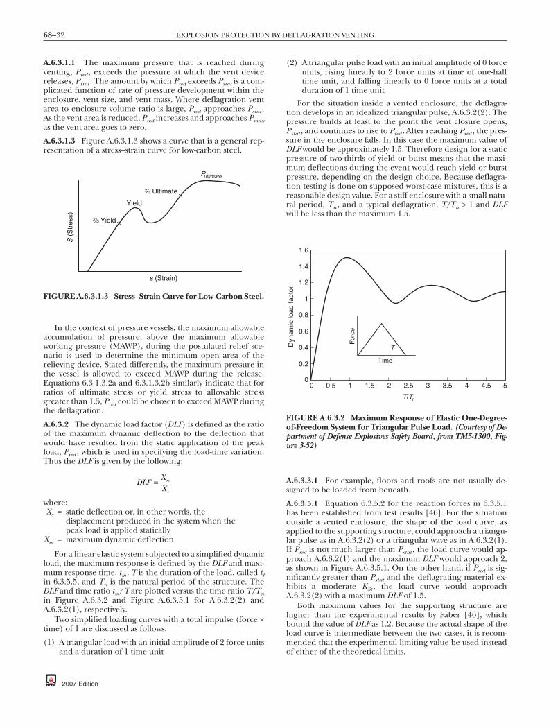
68–32 EXPLOSION PROTECTION BY DEFLAGRATION VENTING
A.6.3.1.1 The maximum pressure that is reached duringventing, Pred , exceeds the pressure at which the vent devicereleases, Pstat . The amount by which Pred exceeds Pstat is a com-plicated function of rate of pressure development within theenclosure, vent size, and vent mass. Where deflagration ventarea to enclosure volume ratio is large, Pred approaches Pstat .As the vent area is reduced, Pred increases and approaches Pmaxas the vent area goes to zero.
A.6.3.1.3 Figure A.6.3.1.3 shows a curve that is a general rep-resentation of a stress–strain curve for low-carbon steel.
In the context of pressure vessels, the maximum allowableaccumulation of pressure, above the maximum allowableworking pressure (MAWP), during the postulated relief sce-nario is used to determine the minimum open area of therelieving device. Stated differently, the maximum pressure inthe vessel is allowed to exceed MAWP during the release.Equations 6.3.1.3.2a and 6.3.1.3.2b similarly indicate that forratios of ultimate stress or yield stress to allowable stressgreater than 1.5, Pred could be chosen to exceed MAWP duringthe deflagration.
A.6.3.2 The dynamic load factor (DLF) is defined as the ratioof the maximum dynamic deflection to the deflection thatwould have resulted from the static application of the peakload, Pred , which is used in specifying the load-time variation.Thus the DLF is given by the following:
DLFXX
m
s
=
where:Xs = static deflection or, in other words, the
displacement produced in the system when thepeak load is applied statically
Xm = maximum dynamic deflection
For a linear elastic system subjected to a simplified dynamicload, the maximum response is defined by the DLF and maxi-mum response time, tm . T is the duration of the load, called tfin 6.3.5.5, and Tn is the natural period of the structure. TheDLF and time ratio tm/T are plotted versus the time ratio T/Tnin Figure A.6.3.2 and Figure A.6.3.5.1 for A.6.3.2(2) andA.6.3.2(1), respectively.
Two simplified loading curves with a total impulse (force ×time) of 1 are discussed as follows:
(1) A triangular load with an initial amplitude of 2 force unitsand a duration of 1 time unit
S (
Str
ess)
s (Strain)
Yield
P
²⁄₃ Yield
²⁄₃ Ultimate
ultimate
FIGURE A.6.3.1.3 Stress–Strain Curve for Low-Carbon Steel.
2007 Edition
(2) A triangular pulse load with an initial amplitude of 0 forceunits, rising linearly to 2 force units at time of one-halftime unit, and falling linearly to 0 force units at a totalduration of 1 time unit
For the situation inside a vented enclosure, the deflagra-tion develops in an idealized triangular pulse, A.6.3.2(2). Thepressure builds at least to the point the vent closure opens,Pstat , and continues to rise to Pred . After reaching Pred , the pres-sure in the enclosure falls. In this case the maximum value ofDLF would be approximately 1.5. Therefore design for a staticpressure of two-thirds of yield or burst means that the maxi-mum deflections during the event would reach yield or burstpressure, depending on the design choice. Because deflagra-tion testing is done on supposed worst-case mixtures, this is areasonable design value. For a stiff enclosure with a small natu-ral period, Tn , and a typical deflagration, T/Tn > 1 and DLFwill be less than the maximum 1.5.
A.6.3.3.1 For example, floors and roofs are not usually de-signed to be loaded from beneath.
A.6.3.5.1 Equation 6.3.5.2 for the reaction forces in 6.3.5.1has been established from test results [46]. For the situationoutside a vented enclosure, the shape of the load curve, asapplied to the supporting structure, could approach a triangu-lar pulse as in A.6.3.2(2) or a triangular wave as in A.6.3.2(1).If Pred is not much larger than Pstat , the load curve would ap-proach A.6.3.2(1) and the maximum DLF would approach 2,as shown in Figure A.6.3.5.1. On the other hand, if Pred is sig-nificantly greater than Pstat and the deflagrating material ex-hibits a moderate KSt , the load curve would approachA.6.3.2(2) with a maximum DLF of 1.5.
Both maximum values for the supporting structure arehigher than the experimental results by Faber [46], whichbound the value of DLF as 1.2. Because the actual shape of theload curve is intermediate between the two cases, it is recom-mended that the experimental limiting value be used insteadof either of the theoretical limits.
54.543.532.5
T/Tn
21.510.50
1.6
1.4
1.2
0.8
0.6
0.4
0.2
0
1D
ynam
ic lo
ad fa
ctor
Time
TF
orce
FIGURE A.6.3.2 Maximum Response of Elastic One-Degree-of-Freedom System for Triangular Pulse Load. (Courtesy of De-partment of Defense Explosives Safety Board, from TM5-1300, Fig-ure 3-52)

68–33ANNEX A
A.6.3.5.2 An example of the calculation of reaction force, Fr ,during venting for a vent area of 1 m2 and a Pred of 1 bar is asfollows:
(1) Av = 1 m2 = 1550 in.2
(2) Pred = 1 bar = 14.5 psi(3) Fr = (1) · (1.2) · (1550) · (14.5) = 26,970 lbf
A.6.3.5.3 In the absence of specific test information or com-bustion modeling results for pressure versus time, a combinedcollapse failure mechanism for structural supports can beevaluated against both idealized pulse and triangular waveloads and be designed based on the maximum DLF.
A.6.3.5.4 The installation of vents of equal area on oppositesides of an enclosure cannot be depended on to prevent thrustin one direction only. It is possible for one vent to open beforeanother. Such imbalance should be considered when design-ing restraints for resisting reaction forces.
A.6.3.5.5 Knowing the duration of the reaction force can aidin the design of certain support structures for enclosures withdeflagration vents. Reference [114] contains several generalequations that approximate the duration of the thrust force ofa dust deflagration. These equations apply only to enclosureswithout vent ducts. This material was contained in theNFPA 68 Impulse Task Force Report to the full committee,September 15, 1999.
A.6.3.5.6 The determination of total impulse uses an equiva-lent static force, which represents the force–time integratedarea as a rectangular pulse with height equal to Fs and a widthequal to tf . The equivalent static force, Fs , to be used for calcu-lating total impulse is based on a load factor of 0.52, as estab-lished from test results [46]:
F Fs r= ( )0 52. ⋅For additional information on derivation of DLF and for use
of the total impulse values, refer to textbooks on structural dy-namics, such as J. M. Biggs, Introduction to Structural Dynamics.
An example of the calculation of duration of reactionforce, tf , and total impulse, I, resulting from venting for thefollowing conditions is as follows:
(1) V = 20 m3
T/Tn
0.10.05 10.5 5 100.01
0.8
0
1.6
2.4
3.2
4
Time T
For
ce
Dynamic load factor
Time of max. response/ load duration
Dyn
amic
load
fact
or
FIGURE A.6.3.5.1 Maximum Response of Elastic One-Degree-of-Freedom System for Triangular Load. (Courtesy ofDepartment of Defense Explosives Safety Board, from TM5-1300,Figure 3-4)
(2) Pmax = 8 bar(3) Pred = 0.4 bar(4) Av = 1.4 m2
(5) tf = (0.0043) · (8/0.4) 0.5 · (20/1.4)(6) tf = 0.27 sec
The reaction force is determined as in 6.3.5.2:(7) Fr = (100) · (1.2) · (1.4) · (0.4)(8) Fr = 67 kN(9) I = (0.52) · (67) · (0.27)
(10) I = 9.4 kN-sec = 9400 N-sec
A.6.4 The Pred developed in a vented enclosure decreases asthe available vent area increases. If the enclosure is small andrelatively symmetrical, one large vent can be as effective asseveral small vents of equal combined area. For large enclo-sures, the location of multiple vents to achieve uniform cover-age of the enclosure surface to the greatest extent practicableis recommended. Rectangular vents are as effective as squareor circular vents of equal area.
A.6.4.3 Example 1. Cylindrical enclosure with a hopper andvented in the roof:
(1) H equals the vertical height of the enclosure = 6 m.(2) Veff equals the total free volume of the enclosure.
(a) The volume of the cylindrical part = (π · D2/4)· h =[π · (1.8)2/4] · 4 = 10.18 m3.
(b) The volume of the hopper, with diameters D1 and D2
= π · h · [(D1)2+ (D1 · D2) + (D2)2]/12 = π · 2 · [(2)2+(2 · 0.5) + (0.5)2]/12 = 2.75 m3.
(c) Veff = 10.18 + 2.75 = 12.93 m3.(d) Veff is the shaded region in Figure A.6.4.3(a).
(3) Aeff = Veff/H = 12.93/6 = 2.155 m2.(4) Dhe = 4 · Aeff/p = (4 · Aeff/ π) 0.5, assuming a cylindrical
cross section.(5) Dhe = 1.656 m.(6) L/D = H/Dhe = 6/1.656 = 3.62.
0.5 m
1.8 m
4 m
6 m
Vent
H
2 m
FIGURE A.6.4.3(a) Calculating L/D Ratio for a CylindricalVessel with a Hopper and a Top Vent.
2007 Edition

68–34 EXPLOSION PROTECTION BY DEFLAGRATION VENTING
In this example, Dhe is less than the diameter of the cylindricalportion of the enclosure; thus L/D will be greater than if it hadbeen calculated by taking the actual physical dimensions.
Example 2. Cylindrical enclosure with a hopper and ventedat the side:
(1) H equals the vertical distance from the bottom of the hop-per to the top of the vent = 4 m.
(2) Veff equals the volume of the hopper plus the volume ofthe cylinder to the top of the vent.(a) The volume of the cylindrical part = (π · D2/4)· h =
[π · (1.8)2/4]· 2 = 5.09 m3.(b) The volume of the hopper, with diameters D1 and D2
= π · h · [(D1)2 + (D1 · D2) + (D22)] / 12 = π · 2 · [(2)2+
(2 · 0.5) + (0.5)2] / 12 = 2.75 m3.(c) Veff = 5.09 + 2.75 = 7.84 m3.(d) Veff is the shaded region in Figure A.6.4.3(b).
(3) Aeff = Veff/H = 7.84/4 = 1.96 m2.(4) Dhe = 4 · Aeff/p = (4 · Aeff / π)0.5, assuming a cylindrical
cross section.(5) Dhe = 1.58 m.(6) L/D = H/Dhe = 4/1.58 = 2.53.
Example 3. Rectangular enclosure with a hopper and a sidevent:
(1) H equals the vertical distance from the bottom of the hop-per to the top of the vent = 5 m.
(2) Veff equals the volume of the hopper plus the volume ofthe rectangular vessel to the top of the vent.(a) The volume of the rectangular part = A · B · h = 1.8
· 1.5 · 3 = 8.1 m3.(b) The volume of the hopper [see Figure A.6.4.3(e)] =
(a1) · h · (b2 − b1)/2 + (b1) · h · (a2 − a1)/2 + h ·(a2 − a1) · (b2 − b1)/3 + (a1) · (b1) · h = (0.5) · 2 ·(1.5 – 0.3)/2 + (0.3) · 2 · (1.8 − 0.5)/2 + 2 ·(1.8 − 0.5) · (1.5 − 0.3)/3 + (0.5) · (0.3) · 2 = 2.33 m3.
(c) Veff = 8.1 + 2.33 = 10.43 m3.(d) V is the shaded region in Figure A.6.4.3(c).
0.5 m
1.8 m
6 m
4 m
2 m
2 mVent
FIGURE A.6.4.3(b) Calculating L/D Ratio for a CylindricalVessel with a Hopper and a Side Vent.
eff
2007 Edition
(3) Aeff = Veff/H = 10.43/5 = 2.09 m2.(4) Dhe = 4 · Aeff / p = (Aeff)
0.5 , assuming a square cross section.Dhe = 1.44 m
(5) L/D = H/Dhe = 5/1.44 = 3.47.
Example 4. Rectangular enclosure with a hopper and a sidevent located close to the hopper:
(1) H equals the vertical distance from the top of the rectan-gular vessel to the bottom of the vent. H is the longestflame path possible because the vent is closer to the hop-per bottom than it is to the vessel top = 4.5 m.
(2) Veff equals the volume from the top of the rectangularvessel to the bottom of the vent.(a) Veff = A · B · h(b) Veff = 1.8 · 1.5 · 4.5 = 12.15 m3.(c) Veff is the shaded region in Figure A.6.4.3(d).
(3) Aeff = Veff/H = 12.1 /4.5 = 2.7 m2.(4) Dhe = 4 · Aeff/p = 4 · Aeff / [2 · (A + B)].
Dhe = 4 · 2.7/[2 · (1.8 + 1.5)] = 1.64 m.(5) L/D = H/Dhe = 4.5/1.64 = 2.74.
Example 5. General calculation of the volume of a hopper.
(1) Rectangular hopper:
Va h b b b h a a
h a a b b
=( ) ( ) −( )
+( ) ( ) ( )
+( ) ( ) ( )
1 2 1 1
2 1
2 2
⋅ ⋅ ⋅ ⋅ −
⋅ − ⋅ −3
2 1
2 1 ++ ( ) ( )a b h1 1⋅ ⋅
(2) Conical hopper:
V hD D D D
= ( )( ) ( ) ( )⎡
⎣⎤⎦π ⋅
+ ⋅ +12
1 2 2
2
12
where:D1 = diameter of the baseD2 = diameter of the top
2 m
4 m
1.5 m1.8 m
H
0.3 m 0.5 m
6 m3 mVent
FIGURE A.6.4.3(c) Rectangular Enclosure with a Hopperand a Side Vent.

68–35ANNEX A
Example 6. Two vents, slightly offset vertically but on oppositesides of the enclosure [see Figure A.6.4.3(f)]. Because the ventsoverlap along the vertical axis, Veff equals the volume from thebottom of the rectangular vessel to the top of the highest vent.
Example 7. Two vents located on the same vertical line, off-set from each other along the central axis, with the upper venttop located at the top of the enclosure [see Figure A.6.4.3(g)].With multiple vents along the central axis, Veff for the bottomvent is the volume from the bottom of the enclosure to the topof the lowest vent. Veff for the next vent is the volume from thetop of the lower vent to the top of the upper vent.
A.6.4.4 The design of deflagration vents and vent closuresnecessitates consideration of many variables, only some ofwhich have been investigated in depth. The technical litera-ture reports extensive experimental work on venting of defla-grations in large enclosures. Equations have been developedthat can be used for determining the necessary vent areas forenclosures [101]. The calculated vent area depends on severalfactors, including the size and strength of the enclosure, thecharacteristics of the fuel/oxidant mixture, and the design ofthe vent itself. The design techniques use one or more empiri-cal factors that allow simplified expressions for the vent area.
1 m
5 m
1.5 m1.8 m
H
0.3 m 0.5 m
6 m4.5 m
Vent
FIGURE A.6.4.3(d) Rectangular Enclosure with a Hopperand a Side Vent Close to the Hopper.
Vertical height h
a2 b2
a1b1
FIGURE A.6.4.3(e) Rectangular Hopper.
The design factors are the result of analyses of numerous ac-tual venting incidents and venting tests that have allowed cer-tain correlations to be made. The user of this standard is urgedto give special attention to all precautionary statements.
The reduced pressure, Pred , in a vented gas deflagrationcan be reduced significantly in certain situations by lining theenclosure interior walls with an acoustically absorbing mate-rial, such as mineral wool or ceramic fiber blankets. Thesematerials inhibit acoustic flame instabilities that are respon-sible for high flame speeds and amplified pressure oscillationsin deflagrations of initially quiescent gas–air mixtures in unob-structed enclosures.
Data [45] show the effects of using 50 mm (2 in.) thick glasswool linings for propane deflagrations in a 5.2 m3(184 ft3) testvessel that is equipped with a 1 m2(10.8 ft2) vent for which Pstatequals 24.5 kPa (3.6 psi). The value of Pred is 34 kPa (4.9 psi) inthe unlined vessel and 5.7 kPa (0.8 psi) (that is, a reduction of
2
1
Veff,H
FIGURE A.6.4.3(f) Rectangular Enclosure, with a Hopperand Two Vents on Opposite Sides of the Enclosure.
Veff2,H2
1
2
Veff1,H1
FIGURE A.6.4.3(g) Rectangular Enclosure with a Hopperand Two Vents on the Same Vertical Line.
2007 Edition

68–36 EXPLOSION PROTECTION BY DEFLAGRATION VENTING
83 percent) where the glass wool lining is installed on two ofthe vessel interior walls.
Data [37] illustrate the effects of a 76 mm (3 in.) thick mineralwool lining for natural gas deflagrations that are centrally ignitedin a 22 m3 (777 ft3) test vessel that is equipped with a 1.1 m2
(11.8 ft2) vent for which Pstat equals 8 kPa (1.2 psi). The mea-sured values of Pred are approximately 60 kPa (8.7 psi) in theunlined vessel and approximately 8 kPa (1.2 psi) (that is, a reduc-tion of 87 percent) where the lining is placed on the floor andthree walls of the vessel.
Similar dramatic reductions in Pred have been obtained inpropane deflagration tests in a 64 m3 (2260 ft3) enclosureusing ceramic fiber blankets on three interior walls [102, 103].
A detailed discussion of the role of acoustic flame instabili-ties in vented gas deflagrations can be found in Solberg, Pap-pas, and Skramstad [44]. Acoustic flame instabilities and en-closure wall linings are important factors in unobstructed,symmetrical enclosures with ignition near the center of theenclosure. Other types of flame instabilities, such as those de-scribed in Solberg, Pappas, and Skramstad [44], that are notinfluenced by enclosure wall linings can have a greater influ-ence on Pred in other situations.
Situations can occur in which it is not possible to providecalculated deflagration venting as described in Chapters 7 and8. Such situations do not justify the exclusion of all venting.The maximum practical amount of venting should be pro-vided because some venting could reduce the damage poten-tial. In addition, consideration should be given to other pro-tection and prevention methods, as found in NFPA 69,Standard on Explosion Prevention Systems.
A.6.4.5 The equations in Chapters 7 and 8 do not preciselypredict the necessary vent area for all enclosures under allconditions. Certain data indicate that the gas-venting equa-tions do not provide sufficient venting in every case [44, 98,99]. Also, tests that involve extreme levels of both congestionand initial turbulence demonstrate that pressures that exceedthose indicated by the equations can occur [42, 87]. Currently,however, the use of the equations is recommended based onsuccessful industrial experience.
As the vent area increases, the reduced pressure for a givenstatic activation pressure of the vent closure decreases. Openvents are generally more effective than covered vents. Ventswith lightweight closures are more responsive than those withheavy closures.
A.6.5.1 If the vent discharges into a congested area, the pres-sure inside the vented enclosure increases. A major blast pres-sure can be caused by the ignition of unburned gases or dustsoutside the enclosure.
If vents are fitted with closure devices that do not remainopen after activation (i.e., self-closing), it should be recog-nized that a vacuum can be created where gases within theenclosure cool. Vacuum within the enclosure could result inequipment damage.
A.6.5.2.1 For further information, see National Association ofCorrosion Engineers Handbook.
A.6.5.7 In some cases, ensuring dependable operation cannecessitate replacing a vent closure.
A.6.6 Deflagration venting is provided for enclosures to mini-mize structural damage to the enclosure itself and to reduce theprobability of damage to other structures. In the case of build-ings, deflagration venting can prevent structural collapse. How-
2007 Edition
ever, personnel within the building can be exposed to the effectsof flame, heat, or pressure.
Damage can result if a deflagration occurs in any enclosurethat is too weak to withstand the pressure from a deflagration.For example, an ordinary masonry wall [200 mm (8 in.) brick,or concrete block 3 m (10 ft) high] cannot withstand a pres-sure difference from one side to the other of much more than0.03 bar (0.5 psi).
Flames and pressure waves that emerge from an enclosureduring the venting process can injure personnel, ignite othercombustibles in the vicinity, result in ensuing fires or second-ary explosions, and result in pressure damage to adjacentbuildings or equipment. The amount of a given quantity ofcombustible mixture that is expelled from the vent, and thethermal and pressure damage that occurs outside of the enclo-sure, depends on the volume of the enclosure, the vent open-ing pressure, and the magnitude of Pred . In the case of a givenenclosure and a given quantity of combustible mixture, alower vent opening pressure results in the discharge of moreunburned material through the vent, resulting in a larger fire-ball outside the enclosure. A higher vent opening pressureresults in more combustion taking place inside the enclosureprior to the vent opening and higher velocity through thevent. (See 6.2.3.) The fireball from vented dust deflagrations ispotentially more hazardous than from vented gas deflagra-tions, because large quantities of unburned dust can be ex-pelled and burned during the venting process.
Deflagration venting generates pressure outside the ventedenclosure. The pressure is caused by venting the primary de-flagration inside the enclosure and by venting the secondarydeflagration outside the enclosure.
A.6.6.2.3 A deflector is considered to be a specific subset ofthe general concept of a barrier. Walls or three-sided contain-ment constructions are used to minimize the hazard of frag-ments and flame impingement from a deflagration; however,if the wall is too close or if the containment volume is toosmall, Pred will increase and pressure will build between thebarrier and the vent. The effectiveness of the wall is limited tothe area immediately behind it. Pressure and flame effects willreform at some point downstream of the wall.
A.6.6.2.4 Other deflector designs are possible, but design in-formation is not available at this time. An alternative could beto use a vent duct consisting of a long radius elbow, accountingfor the effect of vent area according to Chapter 8 for dusts. Avertical barrier wall could result in higher Pred or larger radialhazard distance than an angled deflector, and no design guid-ance can be given.
A.6.6.2.5 A deflector inclined at 45 to 60 degrees can be ap-plied to larger vessels to protect personnel as long as it is in-stalled more than 1.5D from the vent opening so as to notincrease Pred . The ability of this deflector to limit flame lengthfor these larger vessels is uncertain.
A.6.7.1 Table A.6.7.1 demonstrates the effect of vent mass onPred .
A.6.7.2 The preponderance of the available test data indi-cates that Pred increases with panel density. These data havebeen used to develop the equations in this document. How-ever, a limited amount of data demonstrates exceptions to thistrend, especially for initially quiescent gas mixtures whereventing-induced turbulence dominates P .
red
68–37ANNEX A
The greater the mass of the closure, the longer the closuretakes to clear the vent opening completely for a given vent open-ing pressure. Conversely, closures of low mass move away fromthe vent opening more quickly, and venting is more effective.
A.6.7.4 The free area of a vent does not become fully effective inrelieving pressure until the vent closure moves completely out ofthe way of the vent opening. Until this occurs, the closure ob-structs the combustion gases that are issuing from the vent.
In general, a hinged vent closure results in a higher Pred thandoes a rupture diaphragm. The hinged vent closure with its geo-metric area, A1, mass, and static relief pressure, Pstat , is tested inposition on an enclosure under suitable conditions of gas KG ordust KSt , and ignition that closely replicate the intended installa-tion. The Pred is determined experimentally under these condi-tions, and Pred is related to a corresponding vent area, A2, for aninertialess vent closure such as a rupture diaphragm, which re-lieves at the same Pstat and gives the same Pred .
The venting efficiency is given by the following equation:
EAA
=⎛
⎝⎜
⎞
⎠⎟ =2
1
100⋅ percent efficiency (A.6.7.4)
where:E = venting efficiency
A 2 = vent area for inertialess vent closureA 1 = vent area for hinged vent closure
For similarly designed hinged closures, the vent area deter-mined by use of equations in Chapter 7 or Chapter 8 shouldbe corrected by dividing by the demonstrated fractional effi-ciency of the hinged vent closure. This correction would in-clude the otherwise modeled effect of increased inertia. An-nex F provides an alternative method to account for hingedclosures when dealing with dusts.
A.6.8.3 The addition of a vent duct can substantially increasethe pressure developed in a vented enclosure.
A.6.9.1 Even with complete retention of particulates, the im-mediate area surrounding the vent can experience overpres-sure and radiant energy. Such overpressure and radiant en-ergy pose personnel concerns in occupied facilities.
A.6.9.3 The retention of particulates results in a loss of vent-ing efficiency.
Table A.6.7.1 Reduced Pressure (Pred) Developed DuringDeflagration Venting and Influenced by Mass of Vent Closure— 5 Percent Propane in Air, Enclosure Volume = 2.6 m3 [95]
Vent Closure MassStatic
OpeningPressure
(Pstat)(m-bar)
VentClosure
ResponseTime
(m-sec)
ReducedPred
(m-bar)kg/m2 lb/ft2
0.3563 0.073 103 14.5 1563.32 0.68 96 31.0 199
11.17 2.29 100 42.6 23520.79 4.26 100 54.0 314
Notes:(1) L/D = 2.3.(2) Test series reported = #17, #1, #3, and #4.(3) Av = 0.56 m2 (6.0 ft2).
A.6.9.4 Venting indoors affects the building that houses theprotected equipment due to increased pressurization of thesurrounding volume. (See also Section 8.9.) Venting indoors in-creases the potential for secondary explosions. Particulate de-posits in the immediate area can be dislodged by the pressurewave and generate a combustible dust cloud.
A.7.1.1 No venting recommendations are currently availablefor fast-burning gases such as hydrogen with fundamental burn-ing velocities greater than 1.3 times that of propane. Recommen-dations are unavailable because the recommended method al-lows for initial turbulence and turbulence-generating objects,and no venting data have been generated that address conditionsfor fast-burning gas deflagrations. The user is cautioned that fast-burning gas deflagrations can readily undergo transition to deto-nation. NFPA69, Standard on Explosion Prevention Systems, providesalternative measures that should be used.
A.7.1.3 By test, KG of propane is 100 bar-m/sec with a burn-ing velocity of 46 cm/sec. For gases of unknown KG , it is pos-sible to estimate KG from burning velocity using Equation E.1.
A.7.2.2 Equation 7.2.2 was developed from the results of testsand the analysis of industrial accidents. Deflagration ventshave been effective in mitigating the consequences of manyindustrial building explosions. However, it should be notedthat flames and pressure waves from an explosion can be haz-ardous, as described in A.6.6. Furthermore, test work has dem-onstrated that deflagrations of flammable gas mixtures in en-closures that contain turbulence-inducing objects (such asprocess equipment, pipework, cable trays, and so forth) candevelop pressures significantly higher than predicted by Equa-tion 7.2.2. It is therefore recommended that building vents beused in addition to taking measures to minimize the potentialfor flammable gas accumulations in enclosures.
Numerous methods have been proposed for calculatingthe vent closure area [23–27]. Some venting models use thesurface area of the enclosure as a basis for determining ventarea. Analysis of available data [30–45] shows that such meth-ods overcome certain deficiencies associated with previousmethods for calculating vent area.
A.7.2.2.2 Use of Figure 7.2.2.2 provides a way to interpolatebetween the vent parameters previously provided to accom-modate a range of fuels. Methane (previously included in thevent parameter table — Table 6.2.2 of NFPA 68, 2002 edition)has been left out of the curve deliberately because flamespeeds in methane–air mixtures do not accelerate as muchwith turbulence as with other hydrocarbons with similar fun-damental burning velocity.
The shape of the curve beyond 46 cm/sec (151 ft/sec) wasdeveloped based on limited data with fuels of higher burningvelocity. The following information is offered to aid the user indetermining an appropriate burning velocity (and ultimatelyvent parameter C) to use when dealing with aerosols (mists).
The burning velocity of aerosols varies according to thefuel-to-air ratio, droplet diameter, and vapor-fuel-to-total-fuelratio, Ω, as illustrated in Figure A.7.2.2.2(a). The burning ve-locity ratio is the ratio of the mist fundamental burning veloc-ity to that of the pure vapor. The effect of increased burningvelocity for droplet size in the range of 5 to 35 µm is believedto be evident primarily in fluids of relatively low volatility suchas heat transfer fluids that can be released above their atmo-spheric boiling point. In these circumstances, they can forman aerosol consisting of very small droplets that can fall intothe 5 to 35 µm range.
2007 Edition
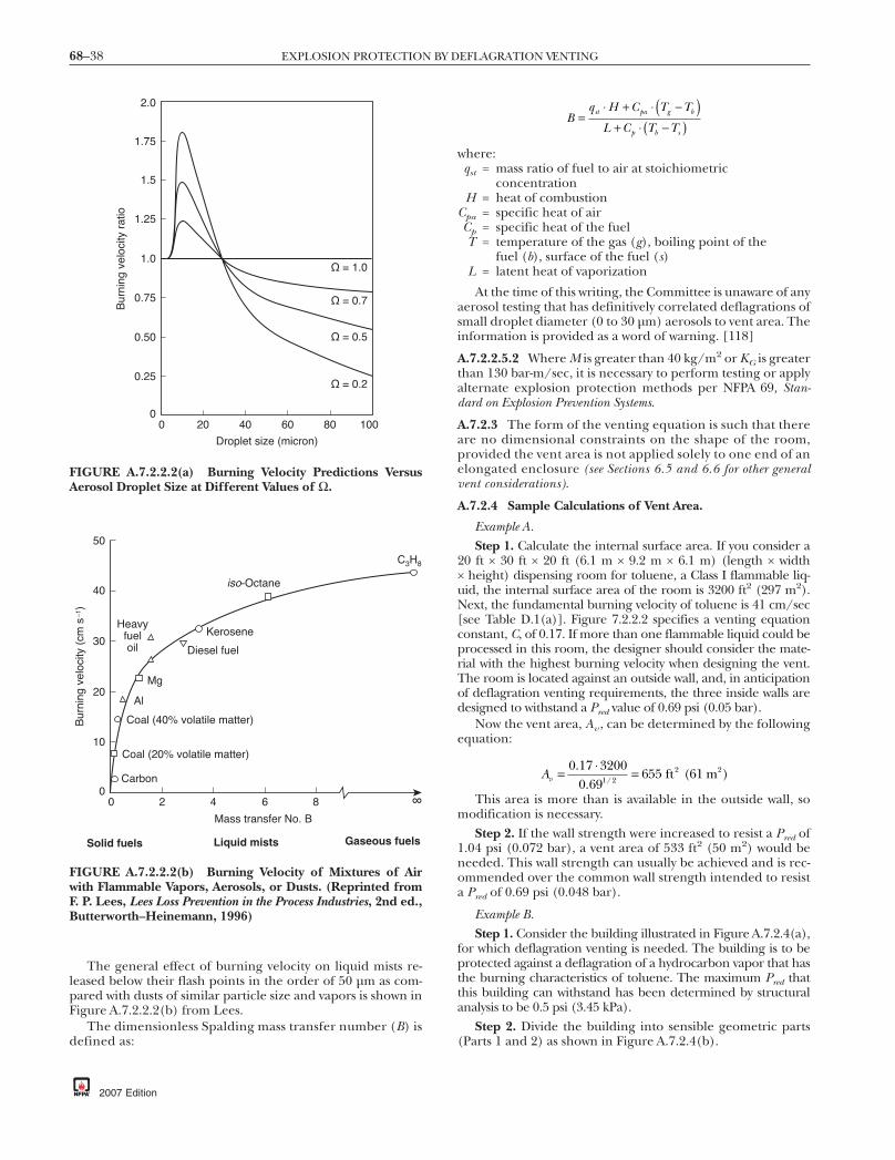
68–38 EXPLOSION PROTECTION BY DEFLAGRATION VENTING
The general effect of burning velocity on liquid mists re-leased below their flash points in the order of 50 µm as com-pared with dusts of similar particle size and vapors is shown inFigure A.7.2.2.2(b) from Lees.
The dimensionless Spalding mass transfer number (B) isdefined as:
40
30
20
0
10
50
Bur
ning
vel
ocity
(cm
s–1
)
∞86420
Mass transfer No. B
Solid fuels
C3H8
iso-Octane
Kerosene
Diesel fuel
Heavy fueloil
Al
Mg
Carbon
Coal (20% volatile matter)
Coal (40% volatile matter)
Liquid mists Gaseous fuels
FIGURE A.7.2.2.2(b) Burning Velocity of Mixtures of Airwith Flammable Vapors, Aerosols, or Dusts. (Reprinted fromF. P. Lees, Lees Loss Prevention in the Process Industries, 2nd ed.,Butterworth–Heinemann, 1996)
2.0
1.25
1.0
0.75
0.50
0.25
0
1.75
1.5
100806040200
Bur
ning
vel
ocity
rat
io
Droplet size (micron)
Ω = 1.0
Ω = 0.7
Ω = 0.5
Ω = 0.2
FIGURE A.7.2.2.2(a) Burning Velocity Predictions VersusAerosol Droplet Size at Different Values of Ω.
2007 Edition
Bq H C T T
L C T Tst pa g b
p b s
=( )
( )⋅ + ⋅ −
+ ⋅ −
where:qst = mass ratio of fuel to air at stoichiometric
concentrationH = heat of combustion
Cpa = specific heat of airCp = specific heat of the fuelT = temperature of the gas (g), boiling point of the
fuel (b), surface of the fuel (s)L = latent heat of vaporization
At the time of this writing, the Committee is unaware of anyaerosol testing that has definitively correlated deflagrations ofsmall droplet diameter (0 to 30 µm) aerosols to vent area. Theinformation is provided as a word of warning. [118]
A.7.2.2.5.2 Where M is greater than 40 kg/m2 or KG is greaterthan 130 bar-m/sec, it is necessary to perform testing or applyalternate explosion protection methods per NFPA 69, Stan-dard on Explosion Prevention Systems.
A.7.2.3 The form of the venting equation is such that thereare no dimensional constraints on the shape of the room,provided the vent area is not applied solely to one end of anelongated enclosure (see Sections 6.5 and 6.6 for other generalvent considerations).
A.7.2.4 Sample Calculations of Vent Area.
Example A.Step 1. Calculate the internal surface area. If you consider a
20 ft × 30 ft × 20 ft (6.1 m × 9.2 m × 6.1 m) (length × width× height) dispensing room for toluene, a Class I flammable liq-uid, the internal surface area of the room is 3200 ft2 (297 m2).Next, the fundamental burning velocity of toluene is 41 cm/sec[see Table D.1(a)]. Figure 7.2.2.2 specifies a venting equationconstant, C, of 0.17. If more than one flammable liquid could beprocessed in this room, the designer should consider the mate-rial with the highest burning velocity when designing the vent.The room is located against an outside wall, and, in anticipationof deflagration venting requirements, the three inside walls aredesigned to withstand a Pred value of 0.69 psi (0.05 bar).
Now the vent area, Av , can be determined by the followingequation:
Av = =0 17 32000 69
611 2
..
)/
⋅655 ft ( m2 2
This area is more than is available in the outside wall, somodification is necessary.
Step 2. If the wall strength were increased to resist a Pred of1.04 psi (0.072 bar), a vent area of 533 ft2 (50 m2) would beneeded. This wall strength can usually be achieved and is rec-ommended over the common wall strength intended to resista Pred of 0.69 psi (0.048 bar).
Example B.Step 1. Consider the building illustrated in Figure A.7.2.4(a),
for which deflagration venting is needed. The building is to beprotected against a deflagration of a hydrocarbon vapor that hasthe burning characteristics of toluene. The maximum Pred thatthis building can withstand has been determined by structuralanalysis to be 0.5 psi (3.45 kPa).
Step 2. Divide the building into sensible geometric parts(Parts 1 and 2) as shown in Figure A.7.2.4(b).

68–39ANNEX A
Step 3. Calculate the total internal surface area of each partof the building.
Part 1 Surface Area (AS1)
Floor = 170 ft × 30 ft = 5100 ft2
(51.8 m × 9.15 m = 474 m2)Roof = 170 ft × 31.6 ft = 5372 ft2
(51.8 m × 9.65 m = 499 m2)Rear wall = 170 ft × 20 ft = 3400 ft2
(51.8 m × 6.1 m = 316 m2)Front wall = (120 ft × 30 ft) + (50 ft × 10 ft)
= 4100 ft2
[(36.6 m × 9.15 m) + (15.25 m × 3.05 m)]= 381 m2
18.3 m (60 ft)
3.05 m(10 ft)
9.65 m(31.6 ft)
6.1 m (20 ft)
15.25 m(50 ft)
9.15 m (30 ft)
51.8 m (170 ft)
18.3 m (60 ft)
Part 1
Part 2
Part 1Part 2Part 1 Part 2
FIGURE A.7.2.4(b) Building Used in Sample Calculation(Not to Scale) (Version II).
18.3 m (60 ft)
3.05 m(10 ft)
9.65 m(31.6 ft)
6.1 m (20 ft)
15.25 m(50 ft)
9.15 m (30 ft)
51.8 m (170 ft)
18.3 m (60 ft)
FIGURE A.7.2.4(a) Building Used in Sample Calculation(Not to Scale) (Version I).
Side walls(rectangularpart)
= 2 × 30 ft × 20 ft = 1200 ft2
(2 × 9.15 m × 6.1 m = 111 m2)
Side walls(triangularpart)
= 30 ft × 10 ft = 300 ft2
(9.15 m × 3.05 m = 28 m2)
Total Part 1: AS1 = 19,472 ft2 (1809 m2)
Part 2 Surface Area (AS2)
Floor = 50 ft × 30 ft = 1500 ft2
(15.25 m × 9.15 m = 139 m2)Roof = 50 ft × 30 ft = 1500 ft2
(15.25 m × 9.15 m = 139 m2)Front wall = 50 ft × 20 ft = 1000 ft2
(15.25 m × 6.1 m = 93 m2)Side walls = 2 × 30 ft × 20 ft = 1200 ft2
(2 × 9.15 m × 6.1 m = 111 m2)Total Part 2: AS2 = 5200 ft2 (483 m2)
Step 4. Thus, the total internal surface area for the wholebuilding, AS , is expressed as follows:
AS = 19,472 ft2 + 5,200 ft2 = 24,672 ft2 (1809 m2 + 483 m2 =2292 m2).
Step 5. Calculate the total vent area, Av , needed usingEquation 7.2.2:
AC APv
s
red
= ⋅1 2/
where:C = 0.17 psi 1/2 (0.045 bar 1/2) from Figure 7.2.2.2
AS = 24,672 ft2 (2292 m2)Pred = 0.5 psi (0.0345 bar)
Step 6. Substituting these values,
Av = =0 17 24 6720 5
5511 2
. ,.
)/
⋅5932 ft ( m2 2
Step 7. The total vent area needed of 5932 ft2 (551 m2)should be divided evenly over the outer surface of the buildingand should be apportioned between the parts in the sameratio as their surface area.
Step 8. Total vent area of Part 1:
A AAAv v
s
s1
1 593219 47224 672
435=⎛
⎝⎜
⎞
⎠⎟ = ⎛
⎝⎜⎞⎠⎟
=⋅ ⋅ ,,
4682 ft ( m2 22)
Step 9. Total vent area of Part 2:
A AAAv v
s
s2
2 59325200
24 672116=
⎛
⎝⎜
⎞
⎠⎟ = ⎛
⎝⎜⎞⎠⎟
=⋅ ⋅,
1250 ft ( m )2 2
Step 10. Check to determine whether sufficient externalsurface area on the building is available for venting.
Step 11. In Part 1, the vent area needed [4682 ft2 (435 m2)]can be obtained by using parts of the front, rear, and side wallsor by using the building roof.
Step 12. In Part 2, the vent area needed [1250 ft2 (116 m2)]can be obtained by using parts of the front and side walls or byusing the building roof.
2007 Edition

68–40 EXPLOSION PROTECTION BY DEFLAGRATION VENTING
Note: Only the outer “skin” of the building can be used forvent locations; a deflagration cannot be vented into otherparts of the building.
A.7.2.4.1.5 Such rooms include adjoining rooms separated by apartition incapable of withstanding the expected pressure.
A.7.2.5 The calculated vent area, Av , can be reduced by in-creasing the value of Pred . The value of Pred should not be in-creased above 0.1 bar (1.5 psi) for the purpose of design un-der this chapter. If Pred is increased above 0.1 bar (1.5 psi), themethods of Section 7.3 should be followed.
The calculated vent area, Av , can be reduced by the instal-lation of a pressure-resistant wall to confine the deflagrationhazard area to a geometric configuration with a smaller inter-nal surface area, AS . The new wall should be designed in ac-cordance with Section 7.3.
The calculated vent area, Av , can be reduced if applicablelarge-scale tests demonstrate that the flammable material has asmaller constant, C, than indicated in Figure 7.2.2.2.
The need for deflagration vents can be eliminated by theapplication of explosion prevention techniques described inNFPA 69, Standard on Explosion Prevention Systems.
A.7.2.6.1 Deflagration vent closures should release at a Pstatvalue that is as low as practical, yet should remain in placewhen subjected to external wind forces that produce negativepressures, to prevent vents from being pulled off. In mostcases, a Pstat value of 0.01 bar (0.14 psi) is acceptable. In areassubject to severe windstorms, release pressures up to 0.015 bar(0.21 psi) are used. In any case, locating vents at building cor-ners and eavelines should be avoided because of the higheruplift pressures in such areas. In hurricane areas, local build-ing codes often require higher resistance to wind uplift. Insuch situations, the limitations of Pstat in 7.2.6.1 should be rec-ognized, and strengthened internal structural elementsshould be provided.
A.7.2.6.3 Such a design ensures that the flow of combustiongases is not impeded by an obstructed closure.
A.7.2.6.4 A vent closure can open if personnel fall or lean on it.
A.7.2.6.6 Situations can arise in which the roof area or one ormore of the wall areas cannot be used for vents, either becauseof the location of equipment or because of exposure to otherbuildings or to areas normally occupied by personnel.
A.7.3.1 Enclosures include process vessels, silos, and otherprocess equipment.
A.7.3.2 Certain basic principles are common to the ventingof deflagrations of gases, mists, and dusts. The principles in-clude, but are not limited to, those discussed in 7.3.2.
The maximum pressure that is reached during venting,Pred , always exceeds the pressure at which the vent device re-leases; in some cases it is significantly higher. Maximum pres-sure is affected by a number of factors.
This section describes the factors and provides guidelinesfor determining maximum pressure.
A.7.3.3.2 Equation 7.3.3.2 is derived from tests made underthe following conditions:
(1) Volumes of test vessels: 2.4 m3, 10 m3, 25 m3, and 250 m3;L/D of test vessels approximately 1
(2) Initial pressure: atmospheric(3) P : 0.1 bar to 0.5 bar
stat2007 Edition
(4) Ignition energy: 10 J(5) Stationary gas mixture at time of ignition(6) No turbulence inducers
A.7.3.3.3 Equation 7.3.3.3.1 was developed based on the fol-lowing considerations:
(1) Flame speeds and values of Pred increase rapidly in elon-gated vessels with L/D greater than the maximum valuefor which Equation 7.3.3.2 is applicable.
(2) Gases with higher values of KG are more prone to flameacceleration in elongated vessels.
(3) Limited data on flame speeds and pressures are availablein Chapter 5, Pipelines, Section 5.1, of W. Bartknecht[101] for propane deflagrations in an open-ended vesselwith L/D of approximately 5.
A.7.3.3.6.2 Where M is greater than 40 kg/m2 or KG is greaterthan 130 bar-m/sec, it is necessary to perform testing or applyalternative explosion protection methods per NFPA 69, Stan-dard on Explosion Prevention Systems.
A.7.4 The deflagration vent area requirement is increasedwhere a vent discharge duct is used. Where a deflagration isvented through a vent duct, secondary deflagrations can occur inthe duct, reducing the differential pressure available across thevent. The sizing equations and graphs in Section H.1 are basedon venting deflagrations to atmosphere without vent ducts.
A.7.4.1 The use of a vent duct with a cross section greaterthan that of the vent can result in a smaller increase in thepressure that develops during venting, Pred , than when using avent duct of an equivalent cross section [93], but this effect isdifficult to quantify because of limited test data.
Vent ducts should be as short and as straight as possible.Any bends can cause dramatic and unpredictable increases inthe pressure that develops during venting.
It should be noted that Pred is still the maximum pressure de-veloped in a vented deflagration. P'red is not an actual pressure.
A.7.4.3 Testing has been done with 3 m (10 ft) and 6 m (20 ft)duct lengths. The effect of ducts longer than 6 m (20 ft) hasnot been investigated in this context.
A.7.4.5 Flames and pressure waves that discharge from theenclosure during venting represent a threat to personnel andcould damage other equipment.
A.7.4.5.1 If a vented enclosure is located within buildings, itshould be placed close to exterior walls so that the vent ductsare as short as possible.
A.7.4.6 The use of a vent duct with a larger cross section thanthat of the vent can result in a smaller increase in the pressurethat develops during venting (Pred) than if using a vent duct ofan equivalent cross section [93], but this effect is difficult toquantify because of limited test data. A special requirement forvent duct cross sections in situations where the vent closuredevice is a hinged panel is discussed in 10.5.1.5.
A.7.4.7 In general, any bends can cause increases in the pres-sure that develops during venting.
A.7.5 In many industrial enclosures, the gas phase is presentin a turbulent condition. An example is the continuous feed ofa flammable gas–oxidant mixture to a catalytic partial oxida-tion reactor. Normally this mixture enters the reactor head asa high-velocity turbulent flow through a pipe. As the gas enters
drodriguez
Resaltado

68–41ANNEX A
the reactor head, still more turbulence develops due to thesudden enlargement of the flow cross section. Appurtenanceswithin an enclosure enhance turbulence.
If the gas system is initially turbulent, the rate of deflagra-tion increases [3, 35]. In such a case, Equations 7.3.3.2 and7.3.3.3.1 do not apply directly. It has been found that initiallyturbulent methane and propane exhibit high values.
The susceptibility of a turbulent system to detonation in-creases with increasing values of the quiescent. In particular,compounds that have values close to that of hydrogen are highlysusceptible to detonation when ignited under turbulent condi-tions. It should be noted that venting tends to inhibit the transi-tion from deflagration to detonation, but it is not an effectivemethod of protecting against the effects of a detonation once thetransition has occurred. Where the likelihood for detonation ex-ists, alternate solutions, such as those in NFPA 69, Standard onExplosion Prevention Systems, should be considered.
In many industrial enclosures, the gas phase is present in aturbulent condition. Internal appurtenances within a ventedenclosure can cause turbulence [55, 102]. If the gas system isinitially turbulent, the rate of deflagration is increased relativeto that observed in initially quiescent conditions [3, 35]. Insuch a case, the equations do not apply directly. It has beenfound that initially turbulent methane and propane exhibitKG values similar to those of initially quiescent hydrogen.
A.7.6.3.1 On the other hand, if pressure excursions are likelyduring operation, it can be the maximum pressure excursionduring operation or the pressure at the relief valve when inthe fully open position.
A.7.6.3.2 Venting from enclosures at initially elevated pres-sures results in severe discharge conditions.
A.7.6.4 The fireball from a vented gas or dust deflagrationpresents a hazard to personnel who may be in the vicinity.People caught in the flame itself will be at obvious risk fromburns, but those who are outside the flame area can be at riskfrom thermal radiation effects. The heat flux produced by thefireball, the exposure time, and the distance from the fireballare important variables to determine the hazard.
A.7.6.4.1 The number of vents, n, should be those vents whosedischarge directions are separate and evenly distributed aroundthe circumference of a vessel or along the central axis. If multiplevent panels cover a single vent opening, they should not betreated as separate for this purpose.
A.8.1.2 The KSt values of dusts of the same chemical composi-tion vary with physical properties such as the size and shape of thedust particle and moisture content. The KSt values published intables are, therefore, examples and represent only the specificdusts tested. (See Annex B.) Mechanical processes that increaseparticle specific surface area, such as grinding, typically increasethe KSt value. The KSt value needs to be verified by specific test ofa dust that has been created by the process that created the dust.There are reasons why this needs to be done.
A.8.2.3.1 Conventional top-fed bins, hoppers, and silos arenot expected to have large volumes occupied by homoge-neous, worst-case dust concentrations. Furthermore, high-turbulence regions in these enclosures are usually limited tothe top of the enclosure.
A.8.2.6.3 The tangential velocity in particulate processingequipment can be generated either by a tangential inlet flow (asin most cyclone dust collectors) or by internal parts within theequipment (as in blenders, hammermills, etc.). In the case of
tangential inlet flow, vtan_max = Qair/Ain , where Qair is the tangen-tial inlet airflow rate (m3/s), and Ain is the inlet cross-sectionalarea (m2). In the case of equipment with rotating internal parts,
vN r
tan_ max
.= ( )2 3 14
60⋅ ⋅ ⋅ (A.8.2.6.3)
where:N = number of revolutions per minute of the moving
partsr = radial length (m) of the largest moving part
In the case where the tangential flow is generated by sta-tionary guide vanes and similar internal parts, the determina-tion of vtan_max is more complicated and requires expert analy-sis or testing.
A.8.2.6.7 The use of a velocity of 20 m/sec and 56 m/sec toseparate the vent area requirements is based on a combination ofthe data used to derive Equation 8.2.2 (the general area correla-tions) and the Tamanini 1990 data [103] in Figure A.8.2.6.7showing how the effective KSt varies with the root-mean-square(rms) turbulence velocity in the vented enclosure. The figure isbased on values of KSt calculated from the nomographs inNFPA 68, plotted as a function of the mean turbulence intensityin the time period when the pressure rise is between 20 percentand 80 percent of maximum value. Because it is very difficult tomeasure rms turbulence velocities in operating equipment, a tur-bulence intensity of 10 percent has been assumed, such that theeffective rms turbulence velocity is 10 percent of the average airvelocity in the operating equipment. Therefore, most userswould be able to calculate the average velocity when decidingwhich vent area equation to use.
The 20 m/sec and 56 m/sec delineating velocities weredetermined by calculating effective KSt values that would beconsistent with the combinations of Av , V, and Pred from theTamanini cornstarch data at an rms turbulence intensity ofabout 2 m/sec for Equation 8.2.2, and for a higher rms veloc-ity as determined by the correlation between KSt and rms ve-locity in Figure A.8.2.6.7.
A.8.2.6.8 Building damaging dust explosions are most oftensecondary dust explosions, where an initial disturbance orsmaller ignition causes a high local turbulence, creating thedust cloud with immediate ignition. To provide enough vent-ing to prevent building failure and additional personnel in-jury, the high-end turbulence correction factor of 1.7 is usedfor buildings.
A.8.2.7 Where M is greater than 40 kg/m2 or KSt > 250 bar-m/sec, see Annex G for guidance.
A.8.3 Dust concentrations in some process equipment andbuildings are inherently limited to only a fraction of the enclo-sure volume.
A.8.3.2 Figure A.8.3.2 illustrates the limits of partial volumecorrections. At low normalized reduced pressures, ∏, the ventratio approaches the fill fraction to the 1/6th power. When fillfraction approaches ∏, both the vent ratio and the necessaryvent area approach zero. Subsections 8.3.3 and 8.3.4 provideguidance on the determination of the fill fraction for processvessels and for buildings, respectively.
A.8.3.3 The fill fraction in a spray dryer depends on the dryerdesign. In the case of a top-loading conical dryer without anyrecirculation or co-feed of dry product, measurements haveindicated that the dry powder concentrations exist only in the
2007 Edition
drodriguez
Resaltado

68–42 EXPLOSION PROTECTION BY DEFLAGRATION VENTING
bottom portion of the dryer, which typically occupies 20 per-cent to 35 percent of the total dryer volume.
Process Equipment Example. A 100 m3 spray dryer with alength/diameter ratio of 1.8 is processing a material with aPmax of 10 bar and a KSt of 100 bar-m/sec at the dryer operat-ing temperature. The deflagration vent design is to be basedon a Pred of 0.50 bar and a Pstat = 0.10 bar. Tests by the manu-facturer, submitted and approved by the authority having juris-diction, have shown that the dry material is confined to the coni-cal lower section of the dryer, which has a volume of 33.3 m3.Therefore, Xr = 0.3333, and ∏ = 0.50/10 = 0.050.
Step 1. Using Equation 8.2.2,
0 2 4 6 8
Average RMS of instantaneous vel
400
300
200
100
0
500
700
600
Max
imum
rat
e of
pre
ssur
e ris
e, K
St (
bar
m/s
)
Cornstarch
Bituminous coal
Range of KSt from20 liter sphere data 50 g of Black Powder
Jet flame i
FIGURE A.8.2.6.7 Explosion Severity for Vented Tests in the
Ven
t rat
io (
Av4
/Av
3)
0.001 0.01 0.1 1
Xr = 0.8
Xr = 0.6
Xr = 0.4
Xr = 0.2
Xr = 0.1
Xr = 0.05
1
0.9
0.8
0.7
0.6
0.5
0.4
0.3
0.2
0.1
0
Normalized reduced pressure π = Pmax
Pred
FIGURE A.8.3.2 Partial Volume Vent Area Reduction.
2007 Edition
A
A
v
v
04 4 3 3 4
0
1 10 1 1 54 0 10 100 1001
0 0501
1
= +⎡⎣ ⎤⎦ −
=
−⋅ ⋅ ⋅ ⋅ ⋅ ⋅. ( . ) ( ).
/ /
..48 m2
Step 2. The partial volume vent area for this application isas follows:
Av 40 3331 48 0 333
0 333 0 0501 0 050
1 16= −−
=( . ) ( . )( . . )
...⋅ ⋅ m2
Step 3. Therefore vent panels with a total vent area of atleast 1.16 m2 should be installed on the conical lower sectionof the dryer.
A.8.5 The flow resistance coefficient K for this correlation isdefined on the static pressure drop, ∆P, from the enclosure tothe duct exit at a given average duct flow velocity, U:
KPU
≡ ∆12
2⋅ ⋅ρAnother convention used by some reference books is to de-
fine K on the total pressure drop or on another velocity scale.The user should ensure that the loss coefficients used in the cal-culations are consistent with the definition of K adopted for thevent duct calculations. See Ural [115] for additional information.
The equations are nonlinear and, under certain combina-tions of input values, result in two possible solutions for ventarea for a given Pred . The lower value of vent area is the mean-ingful solution, and the upper value is an artifact of the formof the equation set. There are certain combinations of Pred andvent duct length where no vent area is large enough and nosolution is obtainable. When this occurs, it could be possibleto vary Pred or vent duct length to converge to a solution. If thatsolution is not satisfactory, NFPA 69, Standard on Explosion Pre-vention Systems, can provide alternatives.
10 12
/s)
14
Cornstarch
” 500 g/m3
Bituminous coal
0.851.69•X + 123.24
0.824.28•X – 17.37
2250 ft3 Chamber.
ocity (m
gnition
R2 =Y = 2
R2 =Y = 1
FMRC

68–43ANNEX A
There is a minimum value for Pred as vent area increases,beyond which solutions are not meaningful. This occurs ap-proximately when the volume of the duct exceeds a fraction ofthe volume of the vessel. When solving the equations, con-straining Avf as follows will typically isolate the smaller root:
A L
Vvf ⋅
≤ 1
For the following input values, Figure A.8.5(a) illustratesthe potential solutions:
V = 500 m3
Pmax = 8.5 barKSt = 150 bar-m/secPstat = 0.05 barPred = 0.5 barVessel L/D = 4ε = 0.26 mm
Straight duct, no elbows, fittings, or rain hats.
Example problem. See Figure A.8.5(b).Example conditions. Given the following:
(1) Enclosure volume, V = 25 (m3)(2) Enclosure L/D = 4(3) Vent diameter, Dv = 1.5 (m)(4) Duct diameter, Dh = 1.5 (m)(5) Av = 1.77 (m2)(6) Pstat = 0.25 (bar-g)(7) KSt = 200 (bar-m/s)(8) Pmax = 8 (bar)(9) Duct length = 12 (m)
(10) Duct effective roughness, ε = 0.26 (mm)(11) Elbows = 2 × 90°(12) Elbow flow resistance = 2 × 1.2 = 2.4(13) Rain hat flow resistance = 0.75
Calculate Pred .While Section 8.5 provides the equations in a form to calcu-
late the vent area based on an allowable P , this example shows
10,000
Duct length (m)
Meaningful
Artifact
1,000
100
10
00 2 4 6 8
Ven
t are
a (m
2 )
FIGURE A.8.5(a) Av vs. Duct Length.
red
how to determine the resulting Pred for a given vent area. In gen-eral, such calculations will be iterative. These input parametersare provided for demonstration purposes. Ural [115] can be ref-erenced for additional discussion on how they were selected.
Solution:
(1) Compute the friction factor for the problem.For practically all vent ducts, the Reynolds number is so
large that a fully turbulent flow regime will be applicable. Inthis regime, the friction factor is only a function of the ratioof the internal duct surface effective roughness (ε) to ductdiameter. The duct friction factor can thus be calculated us-ing a simplified form of the Colebrook equation:
f
D
D
h
=⎛
⎝⎜
⎞
⎠⎟
⎡
⎣⎢
⎤
⎦⎥
⎧
⎨
⎪⎪
⎩
⎪⎪
⎫
⎬
⎪⎪
⎭
⎪⎪
1
1.14 2 log10− ε
2
(A.8.5a)
The effective roughness for smooth pipes and cleansteel pipes is typically 0.0015 mm and 0.046 mm, respec-tively. Recognizing that the pipes used repeatedly incombustion events could be corroded, a value of ε =0.26 mm is assumed.
From Equation A.8.5a, fD = 0.013:
then , andf LD
K Kf LD
K
D
h
inletD
helbows
⋅ ⋅
⋅
= =
= + + +
0 013 121 5
0 107.
..
KK
K
outlet
= + + + =1 5 0 107 2 4 0 75 4 757. . . . .
(A.8.5b)
where:Kinlet = 1.5
Kelbows = 2.4Kexit = 0.75
K = 4.757
Rain cover
Vent cover 90° elbows
Vent duct
Floor
Processenclosure
Roof
FIGURE A.8.5(b) Example Vent Duct Installation.
2007 Edition
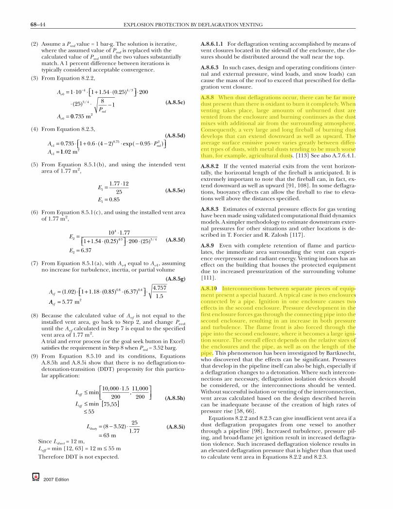
68–44 EXPLOSION PROTECTION BY DEFLAGRATION VENTING
(2) Assume a Pred value = 1 bar-g. The solution is iterative,where the assumed value of Pred is replaced with thecalculated value of Pred until the two values substantiallymatch. A 1 percent difference between iterations istypically considered acceptable convergence.
(3) From Equation 8.2.2,
A
PA
v
red
v
04 4 3
3 4
0
1 10 1 1 54 0 25 200
25 81
= +⎡⎣ ⎤⎦
−
=
−⋅ ⋅ ⋅ ⋅
⋅ ⋅
. ( . )
( )
/
/
00 735 2. m
(A.8.5c)
(4) From Equation 8.2.3,
A PA
v red
v
10 75 2
1
0 735 1 0 6 4 2= + −⎡⎣ ⎤⎦=
. . ( ) ).⋅ ⋅ ⋅ − ⋅exp( 0.95 11 02. m2
(A.8.5d)
(5) From Equation 8.5.1(b), and using the intended ventarea of 1.77 m2,
E
E
1
1
1 77 1225
0 85
=
=
.
.
⋅(A.8.5e)
(6) From Equation 8.5.1(c), and using the installed vent areaof 1.77 m2,
E
E
2
4
3 4
2
10 1 77200 25
6 37
= ⋅⎡⎣ ⎤⎦
=
.( )
.
/1+1.54 ⋅ (0.25) ⋅ ⋅4/3 (A.8.5f)
(7) From Equation 8.5.1(a), with Av4 equal to Av1, assumingno increase for turbulence, inertia, or partial volume
Avf = ⋅ +⎡⎣ ⎤⎦( . ) ...
1 02 1 1 184 7571 5
⋅ (0.85) ⋅ (6.37) ⋅0.8 0.4
AAvf = 5 77 2. m
(A.8.5g)
(8) Because the calculated value of Avf is not equal to theinstalled vent area, go back to Step 2, and change Preduntil the Avf calculated in Step 7 is equal to the specifiedvent area of 1.77 m2.A trial and error process (or the goal seek button in Excel)satisfies the requirement in Step 8 when Pred = 3.52 barg.
(9) From Equation 8.5.10 and its conditions, EquationsA.8.5h and A.8.5i show that there is no deflagration-to-detonation-transition (DDT) propensity for this particu-lar application:
L
L
eff
eff
≤ ⎡⎣⎢
⎤⎦⎥
≤ [ ]≤
min, .
,,
min
10 000 1 5200
11 000200
55
⋅
75,55(A.8.5h)
Ldusty = −=
( . ).
8 3 5225
1 7763
⋅ m
(A.8.5i)
Since Lduct = 12 m,Leff = min [12, 63] = 12 m ≤ 55 mTherefore DDT is not expected.
2007 Edition
A.8.6.1.1 For deflagration venting accomplished by means ofvent closures located in the sidewall of the enclosure, the clo-sures should be distributed around the wall near the top.
A.8.6.3 In such cases, design and operating conditions (inter-nal and external pressure, wind loads, and snow loads) cancause the mass of the roof to exceed that prescribed for defla-gration vent closure.
A.8.8 When dust deflagrations occur, there can be far moredust present than there is oxidant to burn it completely. Whenventing takes place, large amounts of unburned dust arevented from the enclosure and burning continues as the dustmixes with additional air from the surrounding atmosphere.Consequently, a very large and long fireball of burning dustdevelops that can extend downward as well as upward. Theaverage surface emissive power varies greatly between differ-ent types of dusts, with metal dusts tending to be much worsethan, for example, agricultural dusts. [113] See also A.7.6.4.1.
A.8.8.2 If the vented material exits from the vent horizon-tally, the horizontal length of the fireball is anticipated. It isextremely important to note that the fireball can, in fact, ex-tend downward as well as upward [91, 108]. In some deflagra-tions, buoyancy effects can allow the fireball to rise to eleva-tions well above the distances specified.
A.8.8.3 Estimates of external pressure effects for gas ventinghave been made using validated computational fluid dynamicsmodels. A simpler methodology to estimate downstream exter-nal pressures for other situations and other locations is de-scribed in T. Forcier and R. Zalosh [117].
A.8.9 Even with complete retention of flame and particu-lates, the immediate area surrounding the vent can experi-ence overpressure and radiant energy. Venting indoors has aneffect on the building that houses the protected equipmentdue to increased pressurization of the surrounding volume[111].
A.8.10 Interconnections between separate pieces of equip-ment present a special hazard. A typical case is two enclosuresconnected by a pipe. Ignition in one enclosure causes twoeffects in the second enclosure. Pressure development in thefirst enclosure forces gas through the connecting pipe into thesecond enclosure, resulting in an increase in both pressureand turbulence. The flame front is also forced through thepipe into the second enclosure, where it becomes a large igni-tion source. The overall effect depends on the relative sizes ofthe enclosures and the pipe, as well as on the length of thepipe. This phenomenon has been investigated by Bartknecht,who discovered that the effects can be significant. Pressuresthat develop in the pipeline itself can also be high, especially ifa deflagration changes to a detonation. Where such intercon-nections are necessary, deflagration isolation devices shouldbe considered, or the interconnections should be vented.Without successful isolation or venting of the interconnection,vent areas calculated based on the design described hereincan be inadequate because of the creation of high rates ofpressure rise [58, 66].
Equations 8.2.2 and 8.2.3 can give insufficient vent area if adust deflagration propagates from one vessel to anotherthrough a pipeline [98]. Increased turbulence, pressure pil-ing, and broad-flame jet ignition result in increased deflagra-tion violence. Such increased deflagration violence results inan elevated deflagration pressure that is higher than that usedto calculate vent area in Equations 8.2.2 and 8.2.3.
drodriguez
Resaltado
drodriguez
Resaltado
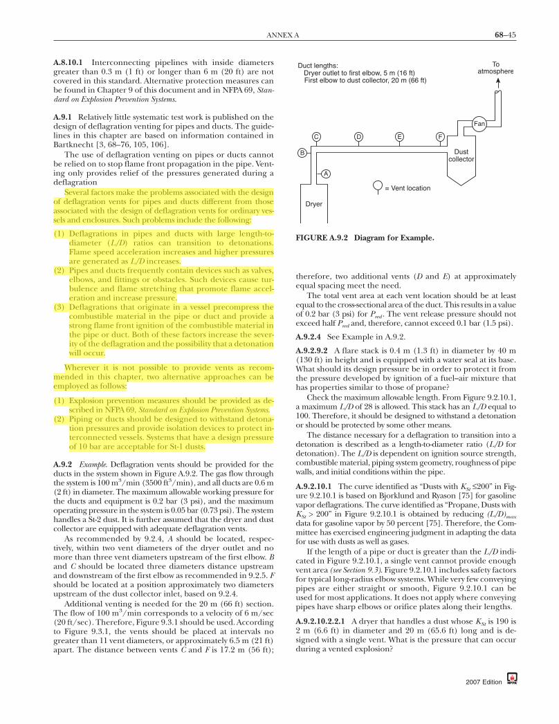
68–45ANNEX A
A.8.10.1 Interconnecting pipelines with inside diametersgreater than 0.3 m (1 ft) or longer than 6 m (20 ft) are notcovered in this standard. Alternative protection measures canbe found in Chapter 9 of this document and in NFPA 69, Stan-dard on Explosion Prevention Systems.
A.9.1 Relatively little systematic test work is published on thedesign of deflagration venting for pipes and ducts. The guide-lines in this chapter are based on information contained inBartknecht [3, 68–76, 105, 106].
The use of deflagration venting on pipes or ducts cannotbe relied on to stop flame front propagation in the pipe. Vent-ing only provides relief of the pressures generated during adeflagration
Several factors make the problems associated with the designof deflagration vents for pipes and ducts different from thoseassociated with the design of deflagration vents for ordinary ves-sels and enclosures. Such problems include the following:
(1) Deflagrations in pipes and ducts with large length-to-diameter (L/D) ratios can transition to detonations.Flame speed acceleration increases and higher pressuresare generated as L/D increases.
(2) Pipes and ducts frequently contain devices such as valves,elbows, and fittings or obstacles. Such devices cause tur-bulence and flame stretching that promote flame accel-eration and increase pressure.
(3) Deflagrations that originate in a vessel precompress thecombustible material in the pipe or duct and provide astrong flame front ignition of the combustible material inthe pipe or duct. Both of these factors increase the sever-ity of the deflagration and the possibility that a detonationwill occur.
Wherever it is not possible to provide vents as recom-mended in this chapter, two alternative approaches can beemployed as follows:
(1) Explosion prevention measures should be provided as de-scribed in NFPA 69, Standard on Explosion Prevention Systems.
(2) Piping or ducts should be designed to withstand detona-tion pressures and provide isolation devices to protect in-terconnected vessels. Systems that have a design pressureof 10 bar are acceptable for St-1 dusts.
A.9.2 Example. Deflagration vents should be provided for theducts in the system shown in Figure A.9.2. The gas flow throughthe system is 100 m3/min (3500 ft3/min), and all ducts are 0.6 m(2 ft) in diameter. The maximum allowable working pressure forthe ducts and equipment is 0.2 bar (3 psi), and the maximumoperating pressure in the system is 0.05 bar (0.73 psi). The systemhandles a St-2 dust. It is further assumed that the dryer and dustcollector are equipped with adequate deflagration vents.
As recommended by 9.2.4, A should be located, respec-tively, within two vent diameters of the dryer outlet and nomore than three vent diameters upstream of the first elbow. Band C should be located three diameters distance upstreamand downstream of the first elbow as recommended in 9.2.5. Fshould be located at a position approximately two diametersupstream of the dust collector inlet, based on 9.2.4.
Additional venting is needed for the 20 m (66 ft) section.The flow of 100 m3/min corresponds to a velocity of 6 m/sec(20 ft/sec). Therefore, Figure 9.3.1 should be used. Accordingto Figure 9.3.1, the vents should be placed at intervals nogreater than 11 vent diameters, or approximately 6.5 m (21 ft)apart. The distance between vents C and F is 17.2 m (56 ft);
therefore, two additional vents (D and E) at approximatelyequal spacing meet the need.
The total vent area at each vent location should be at leastequal to the cross-sectional area of the duct. This results in a valueof 0.2 bar (3 psi) for Pred . The vent release pressure should notexceed half Pred and, therefore, cannot exceed 0.1 bar (1.5 psi).
A.9.2.4 See Example in A.9.2.
A.9.2.9.2 A flare stack is 0.4 m (1.3 ft) in diameter by 40 m(130 ft) in height and is equipped with a water seal at its base.What should its design pressure be in order to protect it fromthe pressure developed by ignition of a fuel–air mixture thathas properties similar to those of propane?
Check the maximum allowable length. From Figure 9.2.10.1,a maximum L/D of 28 is allowed. This stack has an L/D equal to100. Therefore, it should be designed to withstand a detonationor should be protected by some other means.
The distance necessary for a deflagration to transition into adetonation is described as a length-to-diameter ratio (L/D fordetonation). The L/D is dependent on ignition source strength,combustible material, piping system geometry, roughness of pipewalls, and initial conditions within the pipe.
A.9.2.10.1 The curve identified as “Dusts with KSt ≤200” in Fig-ure 9.2.10.1 is based on Bjorklund and Ryason [75] for gasolinevapor deflagrations. The curve identified as “Propane, Dusts withKSt > 200” in Figure 9.2.10.1 is obtained by reducing (L/D)maxdata for gasoline vapor by 50 percent [75]. Therefore, the Com-mittee has exercised engineering judgment in adapting the datafor use with dusts as well as gases.
If the length of a pipe or duct is greater than the L/D indi-cated in Figure 9.2.10.1, a single vent cannot provide enoughvent area (see Section 9.3). Figure 9.2.10.1 includes safety factorsfor typical long-radius elbow systems. While very few conveyingpipes are either straight or smooth, Figure 9.2.10.1 can beused for most applications. It does not apply where conveyingpipes have sharp elbows or orifice plates along their lengths.
A.9.2.10.2.2.1 A dryer that handles a dust whose KSt is 190 is2 m (6.6 ft) in diameter and 20 m (65.6 ft) long and is de-signed with a single vent. What is the pressure that can occurduring a vented explosion?
Duct lengths: Dryer outlet to first elbow, 5 m (16 ft) First elbow to dust collector, 20 m (66 ft)
B
C D E F
A
Dryer
= Vent location
Dustcollector
Fan
Toatmosphere
FIGURE A.9.2 Diagram for Example.
2007 Edition
drodriguez
Resaltado
drodriguez
Resaltado

68–46 EXPLOSION PROTECTION BY DEFLAGRATION VENTING
(1) Maximum Allowable Length. According to Figure 9.2.10.1,an L/D of approximately 25 is allowable. The dryer has anL/D of 10, so this is acceptable.
(2) Maximum Pressure. According to Figure 9.2.10.2.2.1, a pres-sure of approximately 0.5 bar (7.3 psi) develops in suchdryer equipment by means of the deflagration of the speci-fied dust. Therefore, the equipment should have a designpressure of at least this value.
A.9.3 A straight duct that is 1 m (3.3 ft) in diameter and 100 m(330 ft) long is to be protected by deflagration vents. It contains ahydrocarbon–air mixture that has properties similar to those ofpropane. The vent spacing needed to limit the deflagration pres-sure to 0.17 bar (2.5 psi), where the vents are designed to open at0.05 bar (0.73 psi), must be determined. Figure 9.3.1 specifiesthat the vents should be placed no more than 7.6 m (25 ft) apart.To meet this requirement, a vent should be placed at each end,and 13 additional vents should be evenly spaced along the duct.
A.10.1 Openings fitted with fixed louvers can be consideredas open vents. However, the construction of the louvers par-tially obstructs the opening, thus reducing the net free ventarea. The obstruction presented by the louvers decreases theflow rate of gases that pass through the vent and increases thepressure drop across the vent.
A.10.3.2 Specially designed fasteners that fail, under low me-chanical stress, to release a vent closure are commercially avail-able, and some have been tested by listing or approval agencies.
A.10.3.2.2 Large panel closures that are installed on build-ings or other large low-strength enclosures cannot be tested asa complete assembly.
A.10.4 Where the vent closure panel is a double-wall type(such as an insulated sandwich panel), single-wall metal ventpanel restraint systems should not be used. The restraint sys-tem shown in Figure A.10.4(a) should be used for double-wallpanels. The panel area should be limited to 3.1 m2 (33 ft2),and its mass should be limited to 12.2 kg/m2 (2.5 lb/ft2).Forged eyebolts should be used. Alternatively, a “U” bolt canbe substituted for the forged eyebolt. A shock absorber devicewith a fail-safe tether should be provided.
Where large, lightweight panels are used as vent closures, it isusually necessary to restrain the vent closures so that they do notbecome projectile hazards. The restraining method shown in Fig-ureA.10.4(b) illustrates one method that is particularly suited forconventional single-wall metal panels. The key feature of the sys-tem includes a 50 mm (2 in.) wide, 10 gauge bar washer. Thelength of the bar is equal to the panel width, less 50 mm (2 in.)and less any overlap between panels. The bar washer/vent panelassembly is secured to the building structural frame using at leastthree 10 mm (3⁄8 in.) diameter through-bolts.
The restraining techniques shown are very specific to theirapplication and are intended only as examples. Each situationnecessitates an individual design. Any vent restraint designshould be documented by the designer. No restraint for anyvent closure should result in restricting the vent area. It ispossible for a closure tether to become twisted and to thenbind the vent to less than the full opening area of the vent.
The stiffness of the double-wall panel is much greater thanthat of a single-wall panel. The formation of the plastic hingeoccurs more slowly, and the rotation of the panel can be in-complete. Both factors tend to delay or impede venting dur-ing a deflagration.
The component sizes indicated in Figure A.10.4(a) havebeen successfully tested for areas up to 3.1 m2(33 ft2), and for
2007 Edition
mass of up to 12.2 kg/m2 (2.5 lb/ft2). Tests employing fewerthan three rope clips have, in some instances, resulted in slip-page of the tether through the rope clips, thus allowing thepanel to become a free projectile.
The shock absorber is a thick, L-shaped piece of steel plateto which the tether is attached. During venting, the shock ab-sorber forms a plastic hinge at the juncture in the “L,” as theoutstanding leg of the “L” rotates in an effort to follow themovement of the panel away from the structure. The rotationof the leg provides additional distance and time, over whichthe panel is decelerated while simultaneously dissipating someof the panel’s kinetic energy.
Vent panel
Bar washer
Blind rivet
Sheet metal subgirt (10 ga)
Girt
Roof girder
Wire rope clips
203.2 mm
101.6 mm
Close-up of shock absorber
6.35 mmdiam through-bolt
12.7 mm diam forged eye bolt
6.35 mmdiamfail-safetether, 0.61 mlong
Shock absorber (4.8 mm thick) — freedom to move through 90 degree arc
6.35 mm diam, 1.2 m long galv. wire rope tether
12.7 mm diam bolts
241.3 mm
FIGURE A.10.4(a) An Example of a Restraint System forDouble-Wall Insulated Metal Vent Panels.
Bar washer (10 ga)
Vent panel
Building girt
Elevation showing vent panels and bar washer assemblies
+ + ++ + + ++
Bar washer
Lap
Vent panel
Girt
Girt
Girt
Girt
9.5 mmdiam through-bolt
FIGURE A.10.4(b) An Example of a Restraint System forSingle-Wall Metal Vent Panels.

68–47ANNEX A
A.10.5.1 Closures that are held shut with spring-loaded, mag-netic, or friction latches are most frequently used for this formof protection.
A.10.5.1.1 It is important that hinges on hinged vent closuresbe capable of resisting the expected forces. If hinges are weak,if they are attached weakly, or if the door frame is weak, thevent closures can tear away in the course of venting a deflagra-tion. They can become projectile hazards.
A.10.5.1.2 It is difficult to vent equipment of this type if theshell, drum, or enclosure revolves, turns, or vibrates.
A.10.5.1.6 If construction is strong, the vent closure can closerapidly after venting. This can result in a partial vacuum in theenclosure, which in turn can result in inward deformation ofthe enclosure.
Figure 10.5.1.6 shows the vacuum relief vent area, as a func-tion of enclosure size, that is used to prevent the vacuum fromexceeding the vacuum resistance of the enclosure, in millibars.
A.10.5.2 Rupture diaphragms can be designed in round,square, rectangular, or other shapes to effectively providevent relief area to fit the available mounting space. (See Fig-ure A.10.5.2.)
Some materials that are used as rupture diaphragms canballoon, tear away from the mounting frame, or otherwiseopen randomly, leaving the vent opening partially blocked oninitial rupture. Although such restrictions can be momentary,delays of only a few milliseconds in relieving deflagrations ofdusts or gases that have high rates of pressure rise can causeextensive damage to equipment.
FIGURE A.10.5.2 Typical Rupture Diaphragm.
A.10.6 Deflagration venting systems have been developedthat have a rupture membrane for venting and a flame-arresting element. As a deflagration is vented through the sys-tem, any burned and unburned dust is retained within thedevice. Combustion gases are cooled, and no flame emergesfrom the system. In addition, near-field blast effects (overpres-sure) are greatly reduced outside the system. (See Section 6.9and Figure A.10.6.)
A.10.6.3 It is essential that the user work closely with themanufacturer to ensure that all of the parameters are ad-dressed for a safe, reliable installation.
A.11.2 Sample vent closure information form is shown in Fig-ure A.11.2.
A.11.3.4 For symbols, placement, and layout, refer to ANSIZ535, Product Safety Signs and Labels.
A.11.4 Sample annual inspection form is shown in FigureA.11.4.
A.11.4.2 The frequency depends on the environmental andservice conditions to which the devices are to be exposed. Pro-cess or occupancy changes that can introduce significantchanges in condition, such as changes in the severity of corro-sive conditions or increases in the accumulation of deposits ordebris, can necessitate more frequent inspection. It is recom-mended that an inspection be conducted after a process main-tenance turnaround. Inspections should also be conductedfollowing any natural event that can adversely affect the opera-tion and the relief path of a vent closure (for example, hurri-canes or snow and ice accumulations).
A
B
DN
All stainless steelwelded construction
Flame arrester of high-gradestainless-steel mesh
Dust filter of special ceramic-fiber mat with special pressure-wave absorbing coils
Integrated and weldedbursting disc with signal unit and glued gasket, optional aseptic, sanitary, or sterile design
Cabled housing withelectronic service andalarm signal
FIGURE A.10.6 Example of Flame-Arresting and Particulate-Retention Vent System.
2007 Edition

68–48 EXPLOSION PROTECTION BY DEFLAGRATION VENTING
NFPA 68 (p. 1 of 2)© 2007 National Fire Protection Association
VENT CLOSURE INFORMATION FORM
Date:
CONTACT INFORMATION
Company name: Responsible person:
Address: Title:
City: State: Zip code: Telephone:
Telephone: Report writer:
Equipment/process protected:
Vent ID number: Vent location:
Vent size: Vent manufacturer:
Vent type: Vent model number:
Vent opening pressure: Vent construction material:
Vent panel ID:
HAZARD DETAILS
Name of material:
Hazard category: Dust Gas Mist Vapor Hybrid
KSt or KG value of material: bar-m/sec
Pmax value of material: psig or barg
VENT DEVICE DETAILS
Mounting frame: Yes No
Frame type: Welded Bolted
Thermal insulation: Yes No
Gasket material:
Sanitary sealing: Yes No
Vent restraints: Yes No
PROTECTED ENCLOSURE DETAILS Rectangular Bag House (for example)
Enclosure location:
Normal operating pressure: psig @
Normal operating temperature: °F °C
Maximum operating pressure: psig @
Maximum operating temperature: °F °C
Maximum vacuum conditions: psig in. W.C.
FIGURE A.11.2 Sample Vent Closure Information Form.
2007 Edition

68–49ANNEX A
NFPA 68 (p. 2 of 2)© 2007 National Fire Protection Association
VENT CLOSURE INFORMATION FORM (continued)
Frequency and magnitude of pressure cycles:
Vessel volume and dimensions:
Vessel aspect ratio:
Vessel strength:
Design calculations: NFPA 68 Chapter
Other information (to be collected and attached):
Data sheets
Manufacturer’s instruction, installation, and maintenance manuals
Vent closure details
Vent frame
MSDS (of process material)
Material KSt/KG test report (the value used for the vent design)
Copy of vent identification label
Process risk assessment report
Process plan view showing vent relief path
Process elevation view showing vent relief path
Proximity of personnel to vent relief path
Management of change requirements
Mechanical installation details
Manufacturer’s service and maintenance forms
Verification of conformity documentation
Vent restraint documentation
Process interlocks (details)
FIGURE A.11.2 Continued
2007 Edition

68–50 EXPLOSION PROTECTION BY DEFLAGRATION VENTING
NFPA 68 (p. 1 of 2)© 2007 National Fire Protection Association
ANNUAL INSPECTION FORM
USER CONTACT INFORMATION
Company name: Date inspected:
Address: Time:
City: State: Zip code:
Telephone:
Inspector’s name:
Inspection company:
Address:
City: State: Zip code:
Telephone:
Vent ID#:
Vent location:
Vent manufacturer:
INSPECTION
Follow the manufacturer’s recommendations and the following:
Is the vent:
1. Clear of obstructions? Yes No
2. Corroded? Yes No
3. Mechanically or physically damaged? Yes No
4. Clearly labeled: Warning. Explosion relief device? Yes No
5. Clearly tagged/labeled with manufacturer’s information? Yes No
6. Protected from ice and snow? Yes No
7. Painted or coated? (Other than by the manufacturer) Yes No
8. Showing buildup or deposits? Yes No
9. Bulging, damaged, or deformed (from original shape)? Yes No
10. Changed, altered, or tampered with? Yes No
11. Showing signs of fatigue? Yes No
12. Provided with fasteners and mounting hardware in place? Yes No
13. Frame damaged or deformed? Yes No
14. Released? Yes No
15. Opening sensor operable and wiring up to current codes? Yes No
16. Provided with seals, tamper, or other opening indicators intact? Yes No
17. Provided with restraints in place and attached? Yes No
18. Provided with hinges lubricated and operating freely? Yes No
19. Clean and free of contamination? Yes No
FIGURE A.11.4 Sample Annual Inspection Form.
2007 Edition

68–51ANNEX A
NFPA 68 (p. 2 of 2)© 2007 National Fire Protection Association
ANNUAL INSPECTION FORM (continued)
Looking from the vent outward, can you see personnel working or hazardous material being stored in your direct line of sight? Yes No
If yes, please have a process engineer or user/supervisor address your findings as you have described below:
Abnormal conditions found:
Abnormal conditions corrected at time of inspection:
Abnormal conditions that still need attention/addressed:
Action required by management:
Process engineer/supervisor notified? Yes No
Date addressed:
Action required? Yes No
Signature:
Have you observed changes to the process and/or its surroundings that should invoke the company’s management of change procedure? Yes No
Inspector’s signature:
Manager’s signature: Date:
FIGURE A.11.4 Continued
2007 Edition

68–52 EXPLOSION PROTECTION BY DEFLAGRATION VENTING
A.11.5 The vent closure design parameters can include thefollowing items, among others:
(1) Manufacturer(2) Model number(3) Identification number(4) Location(5) Size(6) Type(7) Opening pressure(8) Panel weight(9) Material(s)
A.11.8.2 It is recommended that changes be reviewed withlife safety system and equipment suppliers.
Annex B Fundamentals of Deflagration
This annex is not a part of the requirements of this NFPA documentbut is included for informational purposes only.
B.1 General.
B.1.1 Deflagration Requirements. The following are neces-sary to initiate a deflagration:
(1) Fuel concentration within flammable limits(2) Oxidant concentration sufficient to support combustion(3) Presence of an ignition source
B.1.2 Deflagration Pressure.
B.1.2.1 The deflagration pressure, P, in a closed volume, V, isrelated to the temperature, T, and molar quantity, n, by thefollowing ideal gas law equation:
Pn R T
V= ⋅ ⋅ (B.1.2.1)
where R = universal gas constant.
B.1.2.2 The maximum deflagration pressure, Pmax , and rateof pressure rise, dP/dt, are determined by test over a range offuel concentrations. (See Annex C.) The value of Pmax for mostordinary fuels is 6 to 10 times the absolute pressure at the timeof ignition.
B.1.2.3 The value of (dP/dt)max is the maximum for a particu-lar fuel concentration, referred to as the optimum concentration.(See examples in Figure B.1.2.3.)
B.1.2.4 Based on the KSt values, dusts have been categorizedinto three hazard classes: St-1, St-2, and St-3. These classes in-dicate the relative explosibility hazard and deflagration ventsizing requirements, as shown in Table B.1.2.4.
B.1.2.5 Burning Velocity and Flame Speed.
B.1.2.5.1 The burning velocity is the rate of flame propaga-tion relative to the velocity of the unburned gas that is aheadof it. The fundamental burning velocity, Su , is the burningvelocity of a laminar flame under stated conditions of compo-sition, temperature, and pressure of the unburned gas. Thevalues of Su for many gases have been measured and pub-lished. (See Annex D.)
B.1.2.5.2 Flame speed, Sf , is the speed of a flame front rela-tive to a fixed reference point. Its minimum value is equal tothe fundamental burning velocity times an expansion factorequal to the ratio of the density of the unburned gas to thedensity of the burned gas.
2007 Edition
B.2 Fuel.
B.2.1 General. Any material capable of reacting rapidly andexothermically with an oxidizing medium can be classified as afuel. A fuel can exist in a gas, liquid, or solid state. Liquid fuelsthat are dispersed in air as fine mists, solid fuels that are dis-persed in air as dusts, and hybrid mixtures pose similar defla-gration risks as gaseous fuels.
B.2.2 Concentration. The concentration of a gaseous fuel inair is usually expressed as a volume percentage (vol %) ormole percentage (mol %). The concentrations of disperseddusts and mists are usually expressed in units of mass per unitvolume, such as grams per cubic meter (g/m3).
(bar/sec)
(bar)
10
0 500 1000
Dust concentration
1500 (g/m3)E
xplo
sion
pre
ssur
e (P
ex)
Rat
e of
pre
ssur
e r
ise
(dP
/dt)
10.8 bar = Maximumexplosion pressure Pmax
5
0
400
200
0
432 bar
= Maximum rate of pressure rise(dP/dt)max
sec
FIGURE B.1.2.3 Variation of Deflagration Pressure and De-flagration Index with Concentration for Several Dusts.(Adapted from Bartknecht [51])
Table B.1.2.4 Hazard Classes of Dust Deflagrations
Hazard ClassKSt
(bar-m/sec)*Pmax
(bar)*
St-1 ≤200 10St-2 201–300 10St-3 >300 12
Notes:(1) The application of Figure H.2(a) through Figure H.2(k) is limitedto an upper KSt value of 800.(2) See Annex F for examples of KSt values.*KSt and Pmax are determined in approximately spherical calibratedtest vessels of at least 20 L capacity per ASTM E 1226, Standard TestMethod for Pressure and Rate of Pressure Rise for Combustible Dusts.
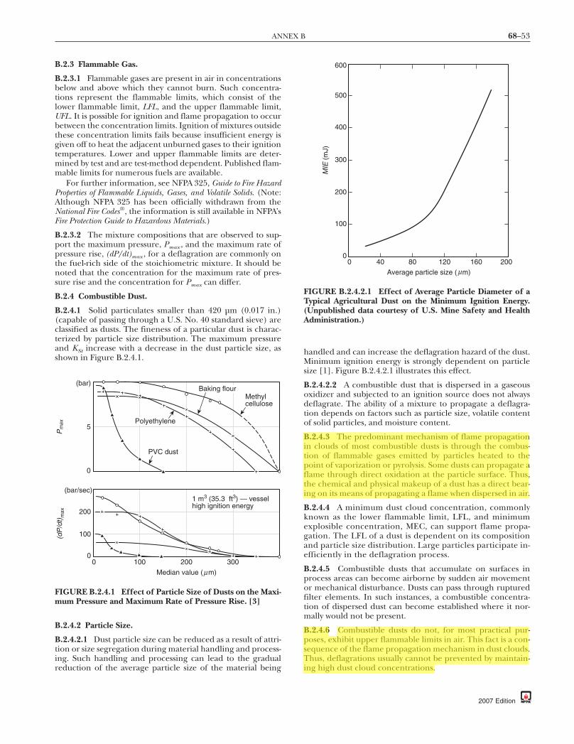
68–53ANNEX B
B.2.3 Flammable Gas.
B.2.3.1 Flammable gases are present in air in concentrationsbelow and above which they cannot burn. Such concentra-tions represent the flammable limits, which consist of thelower flammable limit, LFL, and the upper flammable limit,UFL. It is possible for ignition and flame propagation to occurbetween the concentration limits. Ignition of mixtures outsidethese concentration limits fails because insufficient energy isgiven off to heat the adjacent unburned gases to their ignitiontemperatures. Lower and upper flammable limits are deter-mined by test and are test-method dependent. Published flam-mable limits for numerous fuels are available.
For further information, see NFPA 325, Guide to Fire HazardProperties of Flammable Liquids, Gases, and Volatile Solids. (Note:Although NFPA 325 has been officially withdrawn from theNational Fire Codes®, the information is still available in NFPA’sFire Protection Guide to Hazardous Materials.)
B.2.3.2 The mixture compositions that are observed to sup-port the maximum pressure, Pmax , and the maximum rate ofpressure rise, (dP/dt)max , for a deflagration are commonly onthe fuel-rich side of the stoichiometric mixture. It should benoted that the concentration for the maximum rate of pres-sure rise and the concentration for Pmax can differ.
B.2.4 Combustible Dust.
B.2.4.1 Solid particulates smaller than 420 µm (0.017 in.)(capable of passing through a U.S. No. 40 standard sieve) areclassified as dusts. The fineness of a particular dust is charac-terized by particle size distribution. The maximum pressureand KSt increase with a decrease in the dust particle size, asshown in Figure B.2.4.1.
B.2.4.2 Particle Size.
B.2.4.2.1 Dust particle size can be reduced as a result of attri-tion or size segregation during material handling and process-ing. Such handling and processing can lead to the gradualreduction of the average particle size of the material being
(bar/sec)
(dP
/dt)
max
3002001000
Median value ( m)
200
0
Polyethylene
100
5
0
(bar)
Pm
ax
1 m3 (35.3 ft3) — vessel high ignition energy
PVC dust
Baking flourMethyl cellulose
µ
FIGURE B.2.4.1 Effect of Particle Size of Dusts on the Maxi-mum Pressure and Maximum Rate of Pressure Rise. [3]
handled and can increase the deflagration hazard of the dust.Minimum ignition energy is strongly dependent on particlesize [1]. Figure B.2.4.2.1 illustrates this effect.
B.2.4.2.2 A combustible dust that is dispersed in a gaseousoxidizer and subjected to an ignition source does not alwaysdeflagrate. The ability of a mixture to propagate a deflagra-tion depends on factors such as particle size, volatile contentof solid particles, and moisture content.
B.2.4.3 The predominant mechanism of flame propagationin clouds of most combustible dusts is through the combus-tion of flammable gases emitted by particles heated to thepoint of vaporization or pyrolysis. Some dusts can propagate aflame through direct oxidation at the particle surface. Thus,the chemical and physical makeup of a dust has a direct bear-ing on its means of propagating a flame when dispersed in air.
B.2.4.4 A minimum dust cloud concentration, commonlyknown as the lower flammable limit, LFL, and minimumexplosible concentration, MEC, can support flame propa-gation. The LFL of a dust is dependent on its compositionand particle size distribution. Large particles participate in-efficiently in the deflagration process.
B.2.4.5 Combustible dusts that accumulate on surfaces inprocess areas can become airborne by sudden air movementor mechanical disturbance. Dusts can pass through rupturedfilter elements. In such instances, a combustible concentra-tion of dispersed dust can become established where it nor-mally would not be present.
B.2.4.6 Combustible dusts do not, for most practical pur-poses, exhibit upper flammable limits in air. This fact is a con-sequence of the flame propagation mechanism in dust clouds.Thus, deflagrations usually cannot be prevented by maintain-ing high dust cloud concentrations.
200
MIE
(m
J)
160120800
Average particle size ( m)
40
600
500
400
300
200
100
0
µ
FIGURE B.2.4.2.1 Effect of Average Particle Diameter of aTypical Agricultural Dust on the Minimum Ignition Energy.(Unpublished data courtesy of U.S. Mine Safety and HealthAdministration.)
2007 Edition
drodriguez
Resaltado
drodriguez
Resaltado
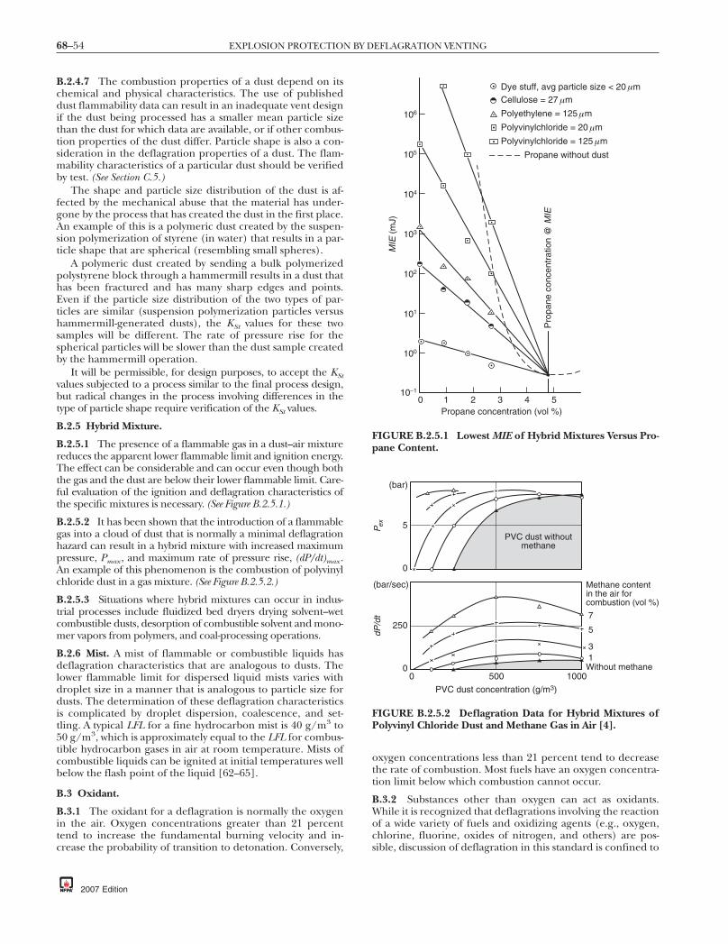
68–54 EXPLOSION PROTECTION BY DEFLAGRATION VENTING
B.2.4.7 The combustion properties of a dust depend on itschemical and physical characteristics. The use of publisheddust flammability data can result in an inadequate vent designif the dust being processed has a smaller mean particle sizethan the dust for which data are available, or if other combus-tion properties of the dust differ. Particle shape is also a con-sideration in the deflagration properties of a dust. The flam-mability characteristics of a particular dust should be verifiedby test. (See Section C.5.)
The shape and particle size distribution of the dust is af-fected by the mechanical abuse that the material has under-gone by the process that has created the dust in the first place.An example of this is a polymeric dust created by the suspen-sion polymerization of styrene (in water) that results in a par-ticle shape that are spherical (resembling small spheres).
A polymeric dust created by sending a bulk polymerizedpolystyrene block through a hammermill results in a dust thathas been fractured and has many sharp edges and points.Even if the particle size distribution of the two types of par-ticles are similar (suspension polymerization particles versushammermill-generated dusts), the KSt values for these twosamples will be different. The rate of pressure rise for thespherical particles will be slower than the dust sample createdby the hammermill operation.
It will be permissible, for design purposes, to accept the KStvalues subjected to a process similar to the final process design,but radical changes in the process involving differences in thetype of particle shape require verification of the KSt values.
B.2.5 Hybrid Mixture.
B.2.5.1 The presence of a flammable gas in a dust–air mixturereduces the apparent lower flammable limit and ignition energy.The effect can be considerable and can occur even though boththe gas and the dust are below their lower flammable limit. Care-ful evaluation of the ignition and deflagration characteristics ofthe specific mixtures is necessary. (See Figure B.2.5.1.)
B.2.5.2 It has been shown that the introduction of a flammablegas into a cloud of dust that is normally a minimal deflagrationhazard can result in a hybrid mixture with increased maximumpressure, Pmax , and maximum rate of pressure rise, (dP/dt)max .An example of this phenomenon is the combustion of polyvinylchloride dust in a gas mixture. (See Figure B.2.5.2.)
B.2.5.3 Situations where hybrid mixtures can occur in indus-trial processes include fluidized bed dryers drying solvent–wetcombustible dusts, desorption of combustible solvent and mono-mer vapors from polymers, and coal-processing operations.
B.2.6 Mist. A mist of flammable or combustible liquids hasdeflagration characteristics that are analogous to dusts. Thelower flammable limit for dispersed liquid mists varies withdroplet size in a manner that is analogous to particle size fordusts. The determination of these deflagration characteristicsis complicated by droplet dispersion, coalescence, and set-tling. A typical LFL for a fine hydrocarbon mist is 40 g/m3 to50 g/m3, which is approximately equal to the LFL for combus-tible hydrocarbon gases in air at room temperature. Mists ofcombustible liquids can be ignited at initial temperatures wellbelow the flash point of the liquid [62–65].
B.3 Oxidant.
B.3.1 The oxidant for a deflagration is normally the oxygenin the air. Oxygen concentrations greater than 21 percenttend to increase the fundamental burning velocity and in-crease the probability of transition to detonation. Conversely,
2007 Edition
oxygen concentrations less than 21 percent tend to decreasethe rate of combustion. Most fuels have an oxygen concentra-tion limit below which combustion cannot occur.
B.3.2 Substances other than oxygen can act as oxidants.While it is recognized that deflagrations involving the reactionof a wide variety of fuels and oxidizing agents (e.g., oxygen,chlorine, fluorine, oxides of nitrogen, and others) are pos-sible, discussion of deflagration in this standard is confined to
MIE
(m
J)
Pro
pane
con
cent
ratio
n @
MIE
0 1 2 3 4 5Propane concentration (vol %)
100
10–1
101
102
103
104
105
106
Dye stuff, avg particle size < 20 mCellulose = 27 m
Polyethylene = 125 m
Polyvinylchloride = 20 m
Polyvinylchloride = 125 m
Propane without dust
µ
µ
µ
µ
µ
FIGURE B.2.5.1 Lowest MIE of Hybrid Mixtures Versus Pro-pane Content.
250
0
(bar/sec)
dP/d
t
Methane content in the air for combustion (vol %)
7
5
31Without methane
5
0
(bar)
P ex
PVC dust without methane
0 500 1000
PVC dust concentration (g/m3)
FIGURE B.2.5.2 Deflagration Data for Hybrid Mixtures ofPolyvinyl Chloride Dust and Methane Gas in Air [4].
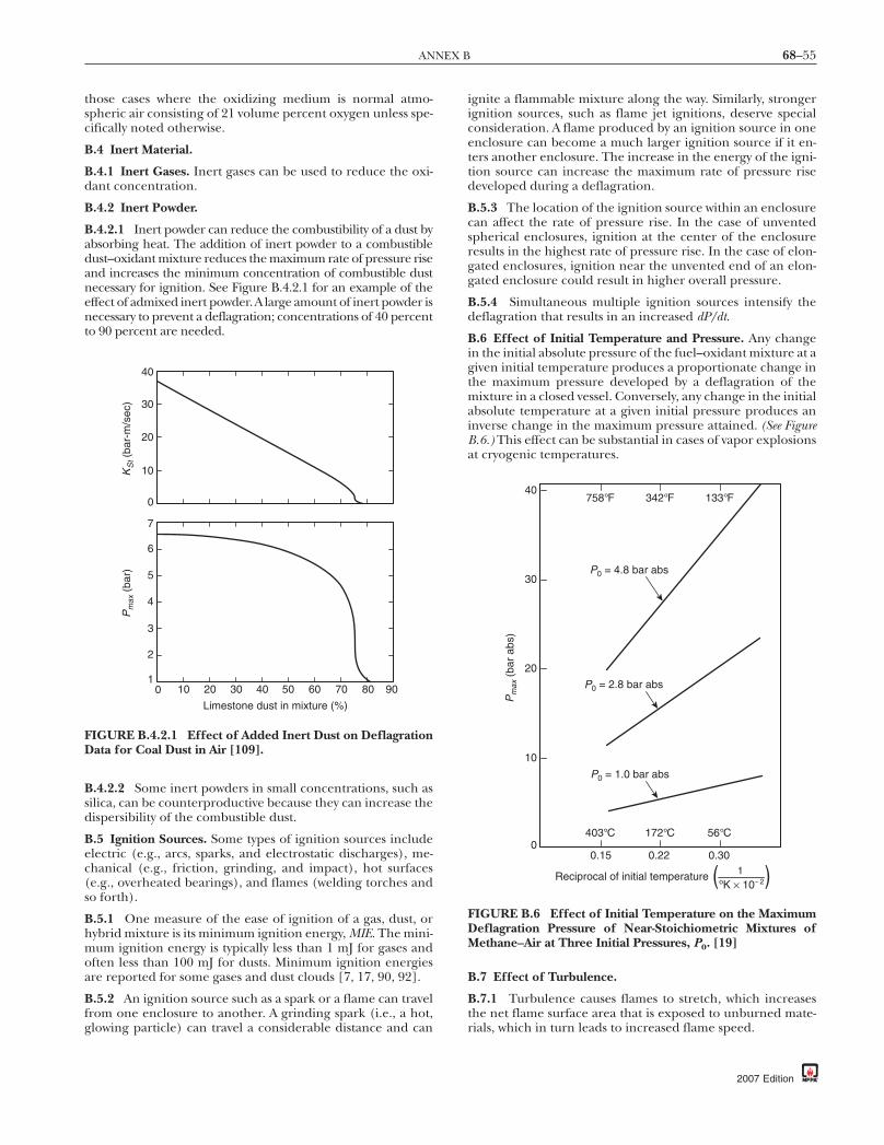
68–55ANNEX B
those cases where the oxidizing medium is normal atmo-spheric air consisting of 21 volume percent oxygen unless spe-cifically noted otherwise.
B.4 Inert Material.
B.4.1 Inert Gases. Inert gases can be used to reduce the oxi-dant concentration.
B.4.2 Inert Powder.
B.4.2.1 Inert powder can reduce the combustibility of a dust byabsorbing heat. The addition of inert powder to a combustibledust–oxidant mixture reduces the maximum rate of pressure riseand increases the minimum concentration of combustible dustnecessary for ignition. See Figure B.4.2.1 for an example of theeffect of admixed inert powder.Alarge amount of inert powder isnecessary to prevent a deflagration; concentrations of 40 percentto 90 percent are needed.
B.4.2.2 Some inert powders in small concentrations, such assilica, can be counterproductive because they can increase thedispersibility of the combustible dust.
B.5 Ignition Sources. Some types of ignition sources includeelectric (e.g., arcs, sparks, and electrostatic discharges), me-chanical (e.g., friction, grinding, and impact), hot surfaces(e.g., overheated bearings), and flames (welding torches andso forth).
B.5.1 One measure of the ease of ignition of a gas, dust, orhybrid mixture is its minimum ignition energy, MIE. The mini-mum ignition energy is typically less than 1 mJ for gases andoften less than 100 mJ for dusts. Minimum ignition energiesare reported for some gases and dust clouds [7, 17, 90, 92].
B.5.2 An ignition source such as a spark or a flame can travelfrom one enclosure to another. A grinding spark (i.e., a hot,glowing particle) can travel a considerable distance and can
Pm
ax (
bar)
0
Limestone dust in mixture (%)
908070605040302010
6
1
2
3
5
7
4
KS
t (ba
r-m
/sec
)
0
20
30
40
10
FIGURE B.4.2.1 Effect of Added Inert Dust on DeflagrationData for Coal Dust in Air [109].
ignite a flammable mixture along the way. Similarly, strongerignition sources, such as flame jet ignitions, deserve specialconsideration. A flame produced by an ignition source in oneenclosure can become a much larger ignition source if it en-ters another enclosure. The increase in the energy of the igni-tion source can increase the maximum rate of pressure risedeveloped during a deflagration.
B.5.3 The location of the ignition source within an enclosurecan affect the rate of pressure rise. In the case of unventedspherical enclosures, ignition at the center of the enclosureresults in the highest rate of pressure rise. In the case of elon-gated enclosures, ignition near the unvented end of an elon-gated enclosure could result in higher overall pressure.
B.5.4 Simultaneous multiple ignition sources intensify thedeflagration that results in an increased dP/dt.
B.6 Effect of Initial Temperature and Pressure. Any changein the initial absolute pressure of the fuel–oxidant mixture at agiven initial temperature produces a proportionate change inthe maximum pressure developed by a deflagration of themixture in a closed vessel. Conversely, any change in the initialabsolute temperature at a given initial pressure produces aninverse change in the maximum pressure attained. (See FigureB.6.) This effect can be substantial in cases of vapor explosionsat cryogenic temperatures.
B.7 Effect of Turbulence.
B.7.1 Turbulence causes flames to stretch, which increasesthe net flame surface area that is exposed to unburned mate-rials, which in turn leads to increased flame speed.
Pm
ax (
bar
abs)
0.150
20
0.22 0.30
Reciprocal of initial temperature 1oK × 10 2
56°C172°C403°C
133°F342°F758°F
10
30
40
P0 = 1.0 bar abs
P0 = 2.8 bar abs
P0 = 4.8 bar abs
( (FIGURE B.6 Effect of Initial Temperature on the MaximumDeflagration Pressure of Near-Stoichiometric Mixtures ofMethane–Air at Three Initial Pressures, P0. [19]
2007 Edition

68–56 EXPLOSION PROTECTION BY DEFLAGRATION VENTING
B.7.2 Initial turbulence in closed vessels results in higherrates of pressure rise and in somewhat higher maximum pres-sure than would occur if the fuel–oxidant mixture were ini-tially subject to quiescent conditions. Turbulence results in anincrease in the vent area needed. Figure B.7.2 illustrates theeffects of turbulence and of fuel concentration.
B.7.3 Turbulence is also created during deflagration as gasesand dusts move past obstacles within the enclosure. In elon-gated enclosures, such as ducts, turbulence generation is en-hanced and flame speeds can increase to high values, causingtransition from deflagration to detonation. Venting, becauseof the flow of unburned gases through the vent opening, cancause turbulence both inside and outside the enclosure.
Annex C Guidelines for Measuring DeflagrationIndices of Dusts and Gases
This annex is not a part of the requirements of this NFPA documentbut is included for informational purposes only.
C.1 General Comments. This annex discusses how the testprocedure relates to the venting of large enclosures, but thetest procedure is not described in detail. ASTM E 1226, Stan-dard Test Method for Pressure and Rate of Pressure Rise for Combus-tible Dusts, sets forth a method for determining the maximumpressure and the rate of pressure rise of combustible dusts[96]. Because gases are not addressed in ASTM E 1226, testprocedures are discussed in this annex.
ASTM E 2019, Standard Test Method for Minimum IgnitionEnergy of a Dust Cloud in Air, and ASTM E 582, Standard TestMethod for Minimum Ignition Energy and Quenching Distance inGaseous Mixtures, provide additional information on test meth-
Pm
ax (
bar
abs)
40
2
Methane (%)
4
6
8
Maximum rate(nonturbulent)
6 8 10 12 140
500
1000
1500
2000
dP/d
t (ba
r/se
c)Maximum rate(turbulent)
Maximum pressure(nonturbulent)
Maximum pressure(turbulent)
FIGURE B.7.2 Effect of Turbulence on the Maximum Pres-sure and Rate of Pressure Rise for Methane–Air Mixtures.(Adapted from [20] and [21])
2007 Edition
ods for dusts and gases. Britton [92] reviewed ignition energytest methods that have been developed for dusts and gases.(See Figure C.1.)
C.2 Purpose. The purpose of deflagration index measure-ments is to predict the effect of the deflagration of a particularmaterial (dust or gas) in a large enclosure without carrying outfull-scale tests.
C.3 Basic Principles. Figure H.1(a) through Figure H.1(g)and Figure H.2(a) through Figure H.2(k), presented in thisstandard, and those in VDI 3673 [104] are based on large-scaletests carried out in vented vessels using a variety of test materi-als and vessel sizes [3, 47]. For each test material and vesselvolume, the maximum reduced deflagration pressure, Pred ,was found for a series of vents with various areas, Av , andopening pressures, Pstat . Only a single material classifica-tion (the KG or KSt index) needs to be experimentally ob-tained for use with Figure H.1(a) through Figure H.1(g)and Figure H.2(a) through Figure H.2(k). If the volumeand mechanical constraints of the enclosure to be pro-tected are known, the user can then determine the ventingneeded from the figures.
C.3.1 The KG and KSt Indices. The test dusts used during thelarge-scale tests were classified according to the maximum rateof pressure rise that was recorded when each was deflagratedin a 1 m3 (35 ft3) closed test vessel. The maximum rate ofpressure rise found in the 1 m3 (35 ft3) vessel was designatedKSt . KSt is not a fundamental material property but dependson the conditions of the test. The classification work carriedout in the 1 m3 (35 ft3) vessel provides the only direct linkbetween small-scale closed vessel tests and the large-scalevented tests on which Figure H.1(a) through Figure H.1(g)and Figure H.2(a) through Figure H.2(k) are based.
It is possible that the KG index can similarly be determinedin a 1 m3(35 ft3) vessel, but published KG values correspond totests made in smaller vessels. The variable KG is known to bevolume-dependent and should not be considered a constant.(See Figure C.1.) Its use is restricted to normalizing data gath-ered under a fixed set of test conditions.
C.3.2 Standardization of a Test Facility. The objective of stan-dardization is to validly compare the deflagration behavior ofa particular material with others for which full-scale test dataare available. Without access to the 1 m3 (35 ft3) vessel inwhich the original KSt classifications were made, it is essentialto standardize the test conditions that are employed usingsamples tested either in the 1 m3(35 ft3) vessel or in a vesselthat has been standardized to it. ASTM defines the standard-ization requirements for dusts. Figure H.1(a) through FigureH.1(g) are based on a series of gas mixtures that were used inthe full-scale tests. The actual KG values are not critical in thecalibration of gases, because it is possible to compare themaximum rate of pressure rise of a particular gas mixture withthose of the gas mixtures represented by Figure H.1(a)through Figure H.1(g). If all values are measured under iden-tical conditions in a vessel that meets certain criteria (see SectionC.4) and adjusted as indicated in Annex E, the figures can beused. To calibrate for dusts, which cannot be identified bycomposition alone, it is necessary to obtain samples that haveestablished KSt values. (See Section C.5.)
C.3.3 Determination of the KG and KSt Indices. If the maxi-mum rate of pressure rise is measured in a vessel with a volumeof other than 1 m3 (35 ft3), Equation C.3.3 is used to normal-
3 3
ize the value obtained to that of a 1 m (35 ft ) vessel.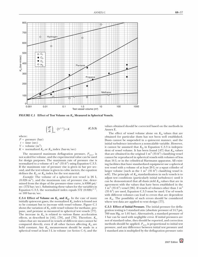
68–57ANNEX C
dPdt
V K⎛⎝⎜
⎞⎠⎟
( ) =max
/⋅ 1 3 (C.3.3)
where:P = pressure (bar)t = time (sec)
V = volume (m3)K = normalized KG or KSt index (bar-m/sec)
The measured maximum deflagration pressure, Pmax , isnot scaled for volume, and the experimental value can be usedfor design purposes. The maximum rate of pressure rise isnormalized to a volume of 1 m3 (35 ft3) using Equation C.3.3.If the maximum rate of pressure rise is given in bar per sec-ond, and the test volume is given in cubic meters, the equationdefines the KG or KSt index for the test material.
Example: The volume of a spherical test vessel is 26 L(0.026 m3), and the maximum rate of pressure rise, deter-mined from the slope of the pressure–time curve, is 8300 psi/sec (572 bar/sec). Substituting these values for the variables inEquation C.3.3, the normalized index equals 572 (0.026)1/3,or 169 bar-m/sec.
C.3.4 Effect of Volume on KG and KSt . In the case of manyinitially quiescent gases, the normalized KG index is found notto be constant but to increase with vessel volume. Figure C.1shows the variation of KG with vessel volume for methane, pro-pane, and pentane as measured in spherical test vessels [77].The increase in KG is related to various flame accelerationeffects, as described in [44], [78], and [79]. Therefore, KGvalues that are measured in vessels of different sizes cannot becompared directly, even if all other factors affecting KG areheld constant. Any KG measurement should be made in aspherical vessel at least 5 L in volume (see Section C.4), and the
KG (
bar-
m/s
ec)
800
0
100
0.001 1.00.10.01
200
300
400
600
500
700
Propane
Pentane
Hydrogen
Test vessel volume (m³
C1
C3
Cs
H2
FIGURE C.1 Effect of Test Volume on KG Measured in Sphe
values obtained should be corrected based on the methods inAnnex E.
The effect of vessel volume alone on KSt values that areobtained for particular dusts has not been well established.Dusts cannot be suspended in a quiescent manner, and theinitial turbulence introduces a nonscalable variable. However,it cannot be assumed that KSt in Equation C.3.3 is indepen-dent of vessel volume. It has been found [47] that KSt valuesthat are obtained in the original 1 m3 (35 ft3) classifying vesselcannot be reproduced in spherical vessels with volumes of lessthan 16 L or in the cylindrical Hartmann apparatus. All exist-ing facilities that have standardized equipment use a sphericaltest vessel with a volume of at least 20 L or a squat cylinder oflarger volume [such as the 1 m3 (35 ft3) classifying vessel it-self]. The principle of KSt standardization in such vessels is toadjust test conditions (particularly initial turbulence) until itcan be demonstrated that all dusts yield KSt values that are inagreement with the values that have been established in the1 m3 (35 ft3) vessel [96]. If vessels of volumes other than 1 m3
(35 ft3) are used, Equation C.3.3 must be used. Use of vesselswith different volumes can lead to errors that are dependenton KSt . The possibility of such errors should be consideredwhere test data are applied to vent design [77].
C.3.5 Effect of Initial Pressure. The initial pressure for defla-gration testing is 1 standard atm (absolute pressure of 14.7 psi,760 mm Hg, or 1.01 bar). Alternatively, a standard pressure of1 bar can be used with negligible error. If initial pressures arenot of standard value, they should be reported, and correctionmethods should be applied. Pmax is proportional to initial testpressure, and any difference between initial test pressure and1 standard atm is multiplied by the deflagration pressure ratio
thane
100 1000
essels.
)
Me
10
rical V
2007 Edition

68–58 EXPLOSION PROTECTION BY DEFLAGRATION VENTING
(usually between 7 and 12) in the measured Pmax value. Mea-sured values are affected to a smaller degree. The effect ofinitial pressure is most important where tests are conducted atambient pressure. Ambient pressure can vary from extremesof absolute pressure of 12.9 psi to 15.6 psi (0.89 bar to 1.08bar), even at sea level, and it decreases with elevation. Forexample, at an elevation of 2 km (1.25 mi), the average abso-lute pressure at a latitude of 50°N is 11.5 psi (0.79 bar abs). It isreadily seen that a Pmax value measured at such an elevation isapproximately 20 percent lower than that measured at 1 stan-dard atm, assuming a 10:1 deflagration pressure ratio. Con-ducting tests under standard conditions, rather than correct-ing the measured values, is always recommended.
C.4 Gas Testing. The test vessel used for gas testing should bespherical, with a volume of at least 5 L and a recommendedvolume of 20 L or greater. Because the only source of initialturbulence is the ignition source employed, it is importantthat the flame front is not unduly distorted by the ignitionprocess. The ignition source should be centrally located andshould approximate a point source. A discrete capacitor dis-charge carrying no great excess of energy above that neededto ignite the mixture is recommended. Fused-wire igniters andchemical igniters can cause multipoint ignition and shouldnot be used for routine KG measurements in small vessels.
Standardized gas mixtures, as identified in Section E.2, canbe initially tested in the system. Verification should be madethat each gas mixture is well mixed and quiescent immediatelyprior to ignition. The maximum rates of pressure rise are mea-sured systematically for several compositions close to the sto-ichiometric mixture until the maximum KG value has beendetermined. A table of KG values is then established for thestandardized gases as measured in the test vessel. The tablevalues are not necessarily the same as the KG values listed inAnnex E.
To subsequently apply the venting requirements to a testgas, the maximum KG value for the test gas first has to bedetermined under conditions identical to those used for stan-dardization. The test material is compared with standardizedgases that have KG values above and below the test value asmeasured in the test vessel. The vent recommendations arethen determined by application of the recommendations forthe standardized gases.
A database in which KG values are given for a wide variety ofgases that have been tested under the standardized conditionsshould be established for the test equipment. KG values shouldnot be reported unless the database, or, at a minimum, the KGvalues for the standardized gases, are also reported.
Most flammable gas mixtures at the optimum concentra-tion can be ignited conveniently in small vessels by using acapacitor spark of 100 mJ or less, which can serve as a normalignition source for standardization. However, the ignition rec-ommendations for certain exceptional gas mixtures can ex-ceed this figure substantially. Before a gas mixture is desig-nated as noncombustible, it should be subjected to a strongignition source. (See Section C.6.)
Although Figure H.1(a) through Figure H.1(g) deal withdeflagrations of gases in air, it can be necessary to predict theeffect of other oxidants such as chlorine. The KG conceptshould not be extended to such cases, except where consider-able expertise can be demonstrated by the test facility. Manygaseous mixtures are incompatible with the test vessel materialand with any trace contaminants within it, including traces ofhumidity. Expert opinion should be sought in the applicationof such test data to the protection of large enclosures.
2007 Edition
C.5 Dust Testing. Dust samples that have the same chemicalcomposition do not necessarily display similar KSt values oreven similar deflagration pressures (Pmax). The burning rate ofa dust depends markedly on the particle size distribution andshape, and on other factors such as surface oxidation (aging)and moisture content. The form in which a given dust is testedshould bear a direct relation to the form of that dust in theenclosure to be protected. Due to the physical factors thatinfluence the deflagration properties of dusts, Figure H.2(a)through Figure H.2(k) do not identify the dusts that are in-volved in large-scale testing, except by their measured KSt val-ues. Although Annex F provides both KSt and dust identitiesfor samples that are tested in a 1 m3 (35 ft3) vessel, it shouldnot be assumed that other samples of the same dusts yield thesame KSt values. Such data cannot be used for vessel standard-ization but are useful in determining trends. The test vesselthat is to be used for routine work should be standardizedusing dust samples whose KSt and Pmax characteristics havebeen established in the standard 1 m3 (35 ft3) vessel [96].
C.5.1 Obtaining Samples for Standardization. Samplesshould be obtained that have established KSt values in St-1,St-2, and St-3 dusts. At the time this standard was published,suitable standard samples (with the exception of lycopodiumdust) were not generally available. ASTM E 1226, Standard TestMethod for Pressure and Rate of Pressure Rise for Combustible Dusts,defines the required agreement with values that are generatedin the standard 1 m3 (35 ft3) vessel.
C.5.2 Effect of Dust-Testing Variables. The following factorsaffect the measured KSt for a particular spherical test vessel (20 Lor greater) and a particular prepared dust sample:
(1) Mass of sample dispersed or concentration(2) Uniformity of dispersion(3) Turbulence at ignition(4) Ignition strength
The concentration is not subject to standardization, be-cause it should be varied for each sample that is tested untilthe maximum KSt has been determined. The maximum KStusually corresponds to a concentration that is several timesgreater than stoichiometric. ASTM E 1226, Standard TestMethod for Pressure and Rate of Pressure Rise for Combustible Dusts,recommends testing a series of concentrations. Measured KStis plotted against concentration, and tests continue until themaximum is determined. By testing progressively leaner mix-tures, the minimum explosive concentration (lean limit orLFL) can similarly be determined. The limit can be affected byignition energy.
C.5.2.1 Obtaining a Uniform Dust Dispersion. The unifor-mity of dust dispersion is implied by the ability to achieve consis-tent and reproducible KSt values in agreement with the estab-lished values for the samples that are tested. Poor dispersionleads to low values of KSt and Pmax .
A number of dust dispersion methods exist. For small ves-sels, the most common methods used are the perforated ringand the whipping hose. The perforated ring (see [96], ASTM E1226, Standard Test Method for Pressure and Rate of Pressure Rise forCombustible Dusts, and Section G.2) fits around the inside surfaceof the test vessel and is designed to disperse the dust in manydirections. A ring of this type is described in Donat [47] inrelation to the dust classification work in the 1 m3 (35 ft3)vessel. However, the device can clog in the presence of waxymaterials, low-density materials, and materials that becomehighly electrically charged during dispersion. To minimize
68–59ANNEX C
these problems, the whipping hose has been used [77]. This isa short length of heavy-duty rubber tubing that “whips” duringdust injection and disperses the dust. Comparison of these twomethods under otherwise identical conditions [77] indicatesthat they are not necessarily interchangeable and that the dis-persion method should be subject to standardization.
C.5.2.2 Standardizing Turbulence at Ignition. During dust in-jection, the partially evacuated test vessel receives a pulse of airfrom the air bomb that brings the pressure to 1 atm (absolute)and disperses dust placed below the dispersion system. Sometime after the end of injection, the igniter is fired. The follow-ing test condition variables affect turbulence at ignition in thetest vessel:
(1) Air bomb volume(2) Air bomb pressure(3) Initial vessel pressure(4) Injection time(5) Ignition delay time
References [77] and [80] describe combinations of thevariables in C.5.2.2(1) through (5) that have yielded satisfac-tory results. For example, a 26 L test vessel [77] employs a 1 Lair bomb at absolute pressure of 300 psi (20.7 bar). Havingestablished the air bomb volume and pressure, the initial testvessel reduced pressure and injection time are set so that, afterdust injection, the test vessel is at 1 atm (absolute). It shouldbe noted that the air bomb and test vessel pressures do notneed to equalize during dust dispersion. Injection time andignition delay time are set using solenoid valves that are oper-ated by a timing circuit. For standardization, reproducibility oftiming is essential, and it is possible that the optimum ignitiondelay time is approximately 10 milliseconds. Fast-acting valvesand accurate timing devices should be employed.
Standardization that uses well-characterized samples (seeC.5.1) is considered complete when samples in St-1, St-2, andSt-3 dusts have been shown to yield the expected KSt (to withinacceptable error) with no adjustment of the variables specifiedin C.5.2.2. In addition, the mode of ignition (see C.5.2.3)should not be changed for standardized testing.
C.5.2.3 Ignition Source. The ignition source can affect deter-mined KSt values even if all other variables determined remainconstant. It has been found that, in a 1 m3 (35 ft3) vessel,capacitor discharge sources of 40 mJ to 16 J provide KSt andPmax data comparable to those obtained using a 10 kJ chemicaligniter [47]. In the same vessel, a permanent spark gap under-rated both KSt and Pmax for a range of samples. References [77]and [81] provide a description of how comparable KSt and Pmax
values were obtained in vessels of approximately 20 L, using be-tween one and six centrally located electric match igniters ratedat 138 J each.
Various types of electrically initiated chemical ignition sourcedevices have proven satisfactory during routine tests. The mostpopular are two 138 J electric match igniters and two 5 kJ pyro-technic devices. These ignition sources are not interchangeable,and standardization should be based on a fixed type of igniter.The matches have insufficient power to ignite all combustibledust suspensions. Therefore, any dust that appears to be classi-fied as St-0 should be retested using two 5 kJ pyrotechnic igniters(see Section C.6). The routine use of the pyrotechnic igniter as astandardized source necessitates a method of correction for itsinherent pressure effects in small vessels [77]. Therefore, neithersource is ideal for all applications.
C.5.3 Dust Preparation for KSt Testing. It is necessary for agiven dust to be tested in a form that bears a direct relation tothe form of that dust in any enclosure to be protected (seeSection C.5). Only standardized dusts and samples taken fromsuch enclosures are normally tested in the as-received state.The following factors affect the KSt :
(1) Size distribution(2) Particle shape(3) Contaminants (gas or solid)
Although dusts can be produced in a coarse state, attritioncan generate fines. Fines can accumulate in cyclones and bag-houses, on surfaces, and in the void space when large enclo-sures are filled. For routine testing, it is assumed that suchfines can be represented by a sample screened to sub-200mesh (75 µm). For comprehensive testing, cascade screeninginto narrow-size fractions of constant weight allows KSt to bedetermined for a series of average diameters. Samples takenfrom the enclosure help in determining representative andworst-case size fractions that are to be tested. If a sufficientsample cannot be obtained as sub-200 mesh (75 µm), it mightbe necessary to grind the coarse material. Grinding can intro-duce an error by affecting the shape of the fines produced.The specific surface of a sample, which affects burning rate,depends on both size distribution and particle shape.
Where fines accumulation is considered, the accumulationof additives also has to be considered. Many dust-handlingprocesses can accumulate additives such as antioxidants thatare included as only a small fraction of the bulk. Such accumu-lation can affect KSt and, by reducing the ignition energy nec-essary to ignite the mixture, can increase the probability of adeflagration [77].
Flammable gases can be present in admixtures with dusts(hybrid mixtures), and many accumulate with time as a resultof gas desorption from the solid phase. Where this possibilityexists, both KSt and ignition energy can be affected. The effectof hybrid mixtures can be synergistic to the deflagration, and agas that is present at only a fraction of its lower flammablelimit needs to be considered [3]. Testing of hybrid mixturescan be carried out by injecting the gas–dust mixture into anidentical gas mixture that is already present in the test vessel.The gas concentration (determined based on partial pressureat the time of ignition) should be systematically varied to de-termine the range of hybrid KSt values that can apply to thepractical system.
The use of a whipping hose (see C.5.2.1) or rebound nozzleshould avoid the necessity of using inert flow-enhancing addi-tives to help dust dispersion in most cases. Such additivesshould not be used in testing.
C.6 Classification as Noncombustible. A gas or dust mixturecannot be classed as noncombustible (for example, St-0 dust)unless it has been subjected repeatedly to a strong chemicalignition source of 10 kJ. If a material fails to ignite over therange of concentrations tested using the standard ignitionsource, then, after the equipment is checked using a materialof known behavior, the test sequence is repeated using a 10 kJchemical igniter. It is necessary to establish that the strongignition source cannot yield a pressure history in the vesselthat can be confused with any deflagration it produces.
It can be impossible to unequivocally determine whether adust is noncombustible in the case of small vessels (e.g., the20 L vessel). Such determination is difficult because strongigniters such as 10 kJ pyrotechnics tend to overdrive the flamesystem, in addition to producing marked pressure effects of
2007 Edition

68–60 EXPLOSION PROTECTION BY DEFLAGRATION VENTING
their own. Cashdollar and Chatrathi [97] have demonstratedthe overdriving effect when determining minimum explosibledust concentrations. Mixtures that are considered to be ex-plosible in a 20 L (0.02 m3) vessel do not propagate flame in a1 m3 (35 ft3) vessel at the same concentration. Cashdollar andChatrathi [97] recommend the use of a 2.5 kJ igniter for lowerflammable limit measurements, which produced results simi-lar to those of the 10 kJ igniter in a 1 m3(35 ft3) vessel. Incontrast, ASTM E 1515, Standard Test Method for MinimumExplosible Concentration of Combustible Dusts, specifies the useof a 5 kJ ignition source for MEC (lower flammable limit)testing. The ideal solution is to use large (10 kJ) igniters inlarger [1 m3 (35 ft3)] vessels. The authors further recom-mend an ignition criterion of an absolute pressure ratiogreater than 2 plus a KSt greater than 1.5 bar-m/sec.
An alternative to the use of the strong ignition source andits associated pressure effects in small vessels is to test fractionsof a finer size than the routine sub-200 mesh (75 µm). Dustignition energy varies with the approximate cube of particlediameter [77]; therefore, the use of electric matches can beextended to identification of St-0 dusts. Similarly, the dust leanlimit concentration can be subject to ignition energy effects,which decrease with the sample’s decreasing particle size.Such effects largely disappear where sub-400 mesh samples aretested. In the case of gases, a strong ignition source that con-sists of capacitance discharges in excess of 10 J, or fused-wiresources of similar energy, can be used. Such sources are rou-tinely used for flammable limit determination.
C.7 Instrumentation Notes. Data can be gathered by analog ordigital methods, but the rate of data collection should be capableof resolving a signal of 1 kHz or higher frequency (for digitalmethods, more than one data point per millisecond). For fast-burning dusts and gases, particularly in small vessels, faster ratesof data logging can be necessary to achieve resolution. Data-logging systems include oscilloscopes, oscillographs, microcom-puters, and other digital recorders. An advantage of digital meth-ods is that both the system operation and subsequent datareduction can be readily automated using computer methods[77]. A further advantage of digital methods is that expansion ofthe time axis enables a more accurate measurement of the slope
of the pressure–time curve than can be obtained from an analog2007 Edition
oscilloscope record. Where using automated data reduction, it isessential to incorporate appropriate logic to mitigate the effect ofspurious electrical signals. Such signals can be reduced by judi-cious cable placement, grounding, and screening, but they aredifficult to avoid altogether. It is advantageous to confirm auto-mated values manually using the pressure–time curve generated.
Where gas mixtures are created by the method of partialpressures, it is important to incorporate a gas-temperaturemeasuring device (for example, a thermocouple) to ensurethat the mixture is created at a constant temperature. Gasanalysis should be used where possible.
It has been found that piezoelectric pressure transducersare satisfactory for deflagration pressure measurements indust-testing systems as a result of good calibration stability.The transducer should be flush-mounted to the inside wall ofthe vessel and coated with silicone rubber, thereby minimizingacoustic and thermal effects.
The entire test system should be routinely maintained andsubjected to periodic tests using standard materials of knownbehavior. Soon after initial standardization, large quantities ofwell-characterized dust samples (St-1, St-2, and St-3) of a typenot subject to aging or other effects should be prepared.Where stored, these dusts can be used for periodic system per-formance tests.
Annex D Fundamental Burning Velocities for SelectFlammable Gases in Air
This annex is not a part of the requirements of this NFPA documentbut is included for informational purposes only.
D.1 General. The values of fundamental burning velocitygiven in Table D.1(a) are based on NACA Report 1300 [82].For the purpose of this guide, a reference value of 46 cm/secfor the fundamental burning velocity of propane has beenused. The compilation given in Perry’s Chemical Engineers’Handbook [83] is based on the same data (NACA Report 1300)but uses a different reference value of 39 cm/sec for the fun-damental burning velocity of propane. The reason for usingthe higher reference value (46 cm/sec) is to obtain closeragreement with more recently published data as presented in
Table D.1(b).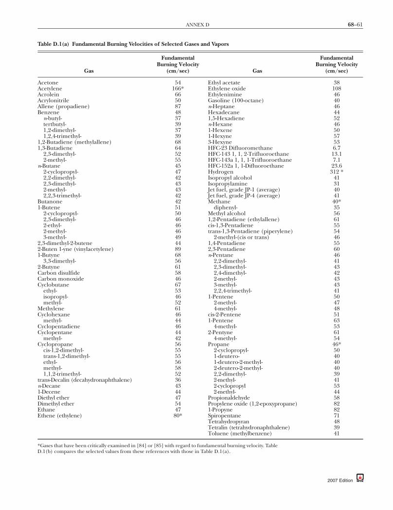
68–61ANNEX D
Table D.1(a) Fundamental Burning Velocities of Selected Gases and Vapors
Gas
FundamentalBurning Velocity
(cm/sec) Gas
FundamentalBurning Velocity
(cm/sec)
Acetone 54 Ethyl acetate 38Acetylene 166* Ethylene oxide 108Acrolein 66 Ethylenimine 46Acrylonitrile 50 Gasoline (100-octane) 40Allene (propadiene) 87 n-Heptane 46Benzene 48 Hexadecane 44
n-butyl- 37 1,5-Hexadiene 52tertbutyl- 39 n-Hexane 461,2-dimethyl- 37 1-Hexene 501,2,4-trimethyl- 39 1-Hexyne 57
1,2-Butadiene (methylallene) 68 3-Hexyne 531,3-Butadiene 64 HFC-23 Difluoromethane 6.7
2,3-dimethyl- 52 HFC-143 1, 1, 2-Trifluoroethane 13.12-methyl- 55 HFC-143a 1, 1, 1-Trifluoroethane 7.1
n-Butane 45 HFC-152a 1, 1-Difluoroethane 23.62-cyclopropyl- 47 Hydrogen 312 *2,2-dimethyl- 42 Isopropyl alcohol 412,3-dimethyl- 43 Isopropylamine 312-methyl- 43 Jet fuel, grade JP-1 (average) 402,2,3-trimethyl- 42 Jet fuel, grade JP-4 (average) 41
Butanone 42 Methane 40*1-Butene 51 diphenyl- 35
2-cyclopropyl- 50 Methyl alcohol 562,3-dimethyl- 46 1,2-Pentadiene (ethylallene) 612-ethyl- 46 cis-1,3-Pentadiene 552-methyl- 46 trans-1,3-Pentadiene (piperylene) 543-methyl- 49 2-methyl-(cis or trans) 46
2,3-dimethyl-2-butene 44 1,4-Pentadiene 552-Buten 1-yne (vinylacetylene) 89 2,3-Pentadiene 601-Butyne 68 n-Pentane 46
3,3-dimethyl- 56 2,2-dimethyl- 412-Butyne 61 2,3-dimethyl- 43Carbon disulfide 58 2,4-dimethyl- 42Carbon monoxide 46 2-methyl- 43Cyclobutane 67 3-methyl- 43
ethyl- 53 2,2,4-trimethyl- 41isopropyl- 46 1-Pentene 50methyl- 52 2-methyl- 47
Methylene 61 4-methyl- 48Cyclohexane 46 cis-2-Pentene 51
methyl- 44 1-Pentene 63Cyclopentadiene 46 4-methyl- 53Cyclopentane 44 2-Pentyne 61
methyl- 42 4-methyl- 54Cyclopropane 56 Propane 46*
cis-1,2-dimethyl- 55 2-cyclopropyl- 50trans-1,2-dimethyl- 55 1-deutero- 40ethyl- 56 1-deutero-2-methyl- 40methyl- 58 2-deutero-2-methyl- 401,1,2-trimethyl- 52 2,2-dimethyl- 39
trans-Decalin (decahydronaphthalene) 36 2-methyl- 41n-Decane 43 2-cyclopropyl 531-Decene 44 2-methyl- 44Diethyl ether 47 Propionaldehyde 58Dimethyl ether 54 Propylene oxide (1,2-epoxypropane) 82Ethane 47 1-Propyne 82Ethene (ethylene) 80* Spiropentane 71
Tetrahydropyran 48Tetralin (tetrahydronaphthalene) 39Toluene (methylbenzene) 41
*Gases that have been critically examined in [84] or [85] with regard to fundamental burning velocity. TableD.1(b) compares the selected values from these references with those in Table D.1(a).
2007 Edition

68–62 EXPLOSION PROTECTION BY DEFLAGRATION VENTING
Table D.1(b) Comparison of Fundamental Burning Velocitiesfor Selected Gases, Fundamental Burning Velocity (cm/sec)
GasTableD.1(a)
Andrews andBradley [84]
France andPritchard
[85] (in air)(in air)(in
oxygen)
Acetylene 166 158 1140 —Ethylene 80 79 — 0Hydrogen 312 310 1400 347Methane 40 45 450 43Propane 46 — — 46
Annex E Deflagration Characteristics of SelectFlammable Gases
This annex is not a part of the requirements of this NFPA documentbut is included for informational purposes only.
E.1 KG Values. As stated in Annex C, the KG value is not con-stant and varies depending on test conditions such as type andamount of ignition energy, volume of test vessel, and other testconditions. Thus, a single value of KG for a particular set of testconditions is only one among a continuum of values that varyover the range of test conditions.
Figure C.1 provides KG values for methane, propane, andpentane over a range of vessel sizes [77].
Table E.1 provides KG values for several gases. The values weredetermined by tests in a 5 L (0.005 m3) sphere with ignition by anelectric spark of approximately 10 J energy. Where the fuels hadsufficient vapor pressure, the tests were done at room tempera-ture. Where the fuels did not have sufficiently high vapor pres-sure, the tests were done at elevated temperature, and the testresults were then extrapolated to room temperature. The sourceof the test data is the laboratory of Dr. W. Bartknecht, Ciba GeigyCo., Basel, Switzerland (private communication).
A KG value for a flammable gas can be approximated from aknown KG value for another flammable gas by the followingequation:
K KS
SG Gu
u
( ) = ( ) ( )( )2
2
11 ⋅ (E.1)
The values for Pmax for the two gases can be measured byactual test under near-identical conditions, or both can be cal-culated for adiabatic combustion conditions. However, onePmax cannot be calculated while the other is measured by test.Optimum mixture is a mixture of the composition that yieldsthe highest maximum pressure during combustion. Usuallythis is not a stoichiometric mixture but a mixture that isslightly richer in fuel gas than stoichiometric. Equation E.1produces the most accurate values where the two flammablegases have similar values of KG .
E.2 Using New KG Data. A method for developing KG valueshas not been standardized. As such, values that are deter-mined by a laboratory can deviate from those employed byBartknecht in developing the correlation coefficients for thevent area equation recommended for use with flammablegases. To maintain consistency in the application of the ventarea equations in Chapter 7, KG data should be adjusted forequivalency with the Bartknecht data as shown in Table E.2.The procedure uses the Bartknecht KG values for methane(55) and propane (100) as points of reference. The followingprocedure is recommended.
2007 Edition
E.2.1 Develop KG values for propane and methane using thesame equipment and method as employed for obtaining dataon other gases of interest.
E.2.2 Compute the linear adjustment coefficients, A and B, asfollows:
BK K
K KG G WB
G G
=( ) − ( )⎡⎣ ⎤⎦( ) − ( )⎡⎣ ⎤⎦
propane methane
propane methaneNNew
(E.2.2a)
A K B KG WB G New= ( ) ( )propane propane− ⋅ (E.2.2b)
where:WB = W. Bartknecht dataNew = New data
E.2.3 The adjusted value of KG that is determined by the newmethod is calculated as follows:
K A B KG adjusted G New( ) ( )= + ⋅ (E.2.3)
Figure E.2.3 shows the correlation for the data reported inTable E.2.
Table E.1 Flammability Properties of Gases 5 L (0.005 m3)sphere; E = 10 J, normal conditions [101]
Flammable MaterialPmax(bar)
KG(bar-m/sec)
Acetophenonea 7.6 109Acetylene 10.6 1415Ammoniab 5.4 10β-Naphtholc 4.4 36Butane 8.0 92Carbon disulfide 6.4 105Diethyl ether 8.1 115Dimethyl
formamidea8.4 78
Dimethyl sulfoxidea 7.3 112Ethanea 7.8 106Ethyl alcohol 7.0 78Ethyl benzenea 7.4 96Hydrogen 6.8 550Hydrogen sulfide 7.4 45Isopropanola 7.8 83Methane 7.1 55Methanola 7.5 75Methylene chloride 5.0 5Methyl nitrite 11.4 111Neopentane 7.8 60Octanola 6.7 95Octyl chloridea 8.0 116Pentanea 7.8 104Propane 7.9 100South African crude
oil6.8–7.6 36–62
Toluenea 7.8 94
aMeasured at elevated temperatures and extrapolated to 25°C (77°F)at normal conditions.bE = 100 J–200 J.c200°C (392°F).

68–63ANNEX F
Table E.2 Gas Explosibility Data as Measured and AdjustedBased on Bartknecht [110]
GasAs
Measured AdjustedPmax(bar)
1,1-Difluoroethane 59 75 7.7Acetone 65 84 7.3Dimethyl ether 108 148 7.9Ethane 78 103 7.4Ethyl alcohol 78 103 7.0Ethylene 171 243 8.0Isobutane 67 87 7.4Methane 46 55 6.7Methyl alcohol 94 127 7.2Propane 76 100 7.3Hydrogen 638 * 6.5
Note: Adjusted KG = –14.0 + 1.50 KG (as measured).*Not recommended due to excessive extrapolation.
Adj
uste
d K
G (
bar-
m/s
ec)
KG, as measured (bar-m/sec)
17550
25
250
200
10050 75 125 150
75
100
125
150
175
225
y = 1.5x −14
FIGURE E.2.3 Reported KG Data. [111]
Table F.1(a) Agricultural Products
Material
Mass MedianDiameter
(µm)
MinimumFlammable
Concentration(g/m3)
Pmax(bar)
Cellulose 33 60 9.7Cellulose pulp 42 30 9.9Cork 42 30 9.6Corn 28 60 9.4Egg white 17 125 8.3Milk, powdered 83 60 5.8Milk, nonfat, dry 60 — 8.8Soy flour 20 200 9.2Starch, corn 7 — 10.3Starch, rice 18 60 9.2Starch, wheat 22 30 9.9Sugar 30 200 8.5Sugar, milk 27 60 8.3Sugar, beet 29 60 8.2Tapioca 22 125 9.4Whey 41 125 9.8
Annex F Deflagration Characteristics of SelectCombustible Dusts
This annex is not a part of the requirements of this NFPA documentbut is included for informational purposes only.
F.1 Introduction. Table F.1(a) through Table F.1(e) are basedon information obtained from Forschungsbericht Staubexplo-sionen [86].
For each dust, the tables show the mass median diameter ofthe material tested as well as the following test results obtainedin a 1 m3 (35 ft3) vessel:
(1) Minimum explosive concentration(2) Maximum pressure developed by the explosion, Pmax
(3) Maximum rate of pressure rise (dP/dt)max
(4) KSt value, which is equivalent to (dP/dt)max because of thesize of the test vessel
(5) Dust hazard class as St-1, St-2, or St-3, as defined in TableB.1.2.4
F.2 Explanation of Test Data. The user is cautioned that testdata on the flammability characteristics of dusts are samplespecific. Dusts that have the same chemical identities — forexample, as a chemical — or that are nominally derived fromthe same sources, such as grain dusts, can vary widely in KStvalues. For example, various calcium stearate dusts have beenfound to have ranges of KSt values that designate the respec-tive dusts as in St-1 through St-3. Therefore, care should betaken in the use of data from these tables.
KStar-m/sec)
Dust HazardClass
229 262 1
202 275 138 128 1
125 1110 1202 2101 1115 1138 182 159 162 1
140 1
(b
Wood flour 29 — 10.5 205 2
2007 Edition
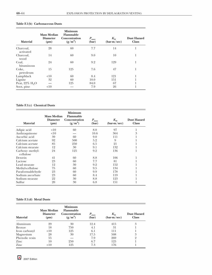
68–64 EXPLOSION PROTECTION BY DEFLAGRATION VENTING
able F.1(b) Carbonaceous Dusts
Material
Mass MedianDiameter
(µm)
MinimumFlammable
Concentration(g/m3)
Pmax(bar)
harcoal,activated
28 60 7.7
harcoal,wood
14 60 9.0
oal,bituminous
24 60 9.2
oke,petroleum
15 125 7.6
ampblack <10 60 8.4ignite 32 60 10.0eat, 22% H2O — 125 84.0oot, pine <10 — 7.9
able F.1(c) Chemical Dusts
Material
Mass MedianDiameter
(µm)
MinimumFlammable
Concentration(g/m3)
Pmax(bar)
dipic acid <10 60 8.0nthraquinone <10 — 10.6scorbic acid 39 60 9.0alcium acetate 92 500 5.2alcium acetate 85 250 6.5alcium stearate 12 30 9.1arboxy- methyl-cellulose
24 125 9.2
extrin 41 60 8.8actose 23 60 7.7ead stearate 12 30 9.2ethyl-cellulose 75 60 9.5
araformaldehyde 23 60 9.9odium ascorbate 23 60 8.4odium stearate 22 30 8.8ulfur 20 30 6.8
able F.1(d) Metal Dusts
aterial
Mass MedianDiameter
(µm)
MinimumFlammable
Concentration(g/m3)
Pmax(bar)
luminum 29 30 12.4ronze 18 750 4.1
ron carbonyl <10 125 6.1agnesium 28 30 17.5
henolic resin 55 — 7.9inc 10 250 6.7inc <10 125 7.3
2007 Edition
KStar-m/sec)
Dust HazardClass
14 1
10 1
129 1
47 1
121 1151 167 126 1
KStbar-m/sec)
Dust HazardClass
97 1364 3111 19 121 1
132 1136 1
106 181 1
152 1134 1178 1119 1123 1151 1
KStar-m/sec)
Dust HazardClass
415 331 1
111 1508 3269 2125 1176 1
T
(b
C
C
C
C
LLPS
T
(
AAACCCC
DLLMPSSS
T
M (b
ABIMPZZ

68–65ANNEX G
Annex G Calculation Method for Correction FactorDue to Increased Vent Panel Mass
This annex is not a part of the requirements of this NFPA documentbut is included for informational purposes only.
G.1 General. The following procedure can be used to assessthe impact of the vent panel mass on Pred .
G.1.1 Introduction. The mass of vent panels is a factor thatcan limit the effectiveness of the venting process. To properlyassess the influence panel mass contributes, other factors mustalso be considered, such as the reactivity of the dust, the enclo-sure volume and the number, shape, size, and type of deflagra-tion vents utilized. The procedures for determining the effectsof vent panel inertia on deflagration venting are presented inthis section. The theoretical development uses mostly absolutepressures, instead of the gauge pressures used in the remain-der of this document, and new pressure terms are defined.Pressures are used in bar, bar-abs, and pascals-abs; thus thereader is cautioned to note units of measure directly following
Table F.1(e) Plastic Dusts
Material
MassMedian
Diameter(µm)
MinimumFlammable
Concentration(g/m3)
Pm(ba
(poly) Acrylamide 10 250 5(poly) Acrylonitrile 25 — 8(poly) Ethylene
(low-pressure process)<10 30 8
Epoxy resin 26 30 7Melamine resin 18 125 10Melamine, molded (wood
flour and mineral filledphenol-formaldehyde)
15 60 7
Melamine, molded(phenol-cellulose)
12 60 10
(poly) Methyl acrylate 21 30 9(poly) Methyl acrylate,
emulsion polymer18 30 10
Phenolic resin <10 15 955 7
(poly) Propylene 25 30 8Terpene-phenol resin 10 15 8Urea-formaldehyde/
cellulose, molded13 60 10
(poly) Vinyl acetate/ethylene copolymer
32 30 8
(poly) Vinyl alcohol 26 60 8(poly) Vinyl butyral 65 30 8(poly) Vinyl chloride 107 200 7(poly) Vinyl
chloride/vinylacetylene emulsioncopolymer
35 60 8
(poly) Vinylchloride/ethylene/vinylacetylene suspensioncopolymer
60 60 8
each equation.
G.1.2 The reduced deflagration pressure is first calculatedusing Equation 8.2.2, based on low-mass vents. Correctionsfor vessel L/D and partial volume can then be added. Thiswill be an iterative solution for the Pred resulting from theassumed vent area. Next, the correction factors for inertiaeffects are calculated.
G.1.3 The inertia of the panel can manifest itself in the fol-lowing two ways:
(1) As a new factor in the effective vent relief pressure, pvi ,higher than the nominal static value, pv
(2) As a higher reduced pressure, pri , after full vent deploy-ment with respect to the pri0 in the absence of inertia.
The highest pressure during the vented deflagration can oc-cur either at the point of vent relief or later after vent deploy-ment. As inertia of the panel affects both pressures, both effectshave to be calculated and the higher value, pvi or pri , used as thereduced pressure produced in the vented deflagration.
KSt(bar-m/sec)
DustHazardClass
12 1121 1156 1
129 1110 141 1
127 1
269 2202 2
129 1269 2101 1143 1136 1
119 1
128 1147 146 195 1
98 1
axr)
.9
.5
.0
.9
.2
.5
.0
.4
.1
.3
.9
.4
.7
.2
.6
.9
.9
.6
.2
.3
2007 Edition

)
68–66 EXPLOSION PROTECTION BY DEFLAGRATION VENTING
G.1.3.1 The inertia correction is limited to the following:
(1) Vent panel density, σv < 200 kg/m2
(2) Nominal static relief pressure, pv < 0.5 bar
G.1.4 Both inertia effects are evaluated using two dimension-less parameters, Σ and Γ. However, one term in the param-eters is different, that is, the dust reactivity. In the first case, thedeflagration index, KSt , is used to determine ΣKSt
and ΓKSt. In
the second case, the effective mixture reactivity, K, is used todetermine ΣK and ΓK.
G.1.5 The deflagration index, KSt , of a dust is basically themaximum rate of pressure rise generated in a confined defla-gration. The effective mixture reactivity is a parameter basedon KSt , but it contains two corrections to account for the ef-fects of the deflagration vent relief pressure and the volume ofthe protected enclosure. The vent relief pressure correction isthe following:
K Kp
pSt v Stv
, .= +⎛
⎝⎜
⎞
⎠⎟
⎡
⎣⎢⎢
⎤
⎦⎥⎥
⋅ ⋅1 1 750
∆ (G.1.5a)
where:KSt,v = deflagration index with vent relief pressure
correctionKSt = deflagration index (bar-m/sec)∆pv = vent relief pressure (bar) = Pstatp 0 = initial pressure (bar-abs)
The volume correction for Equation G.1.5a is the following:
K KV
St v= ⎛⎝⎜
⎞⎠⎟,
.
⋅10 3
0 11
m(G.1.5b)
where:K = volume correction to deflagration indexV = enclosure volume (m3)
This volume correction is applied only where the enclosurevolume is greater than 10 m3; otherwise K = KSt,v .
G.1.6 The shape factor for the vent(s) is as follows:For square panels, cs = 1.For circular panels, cs = 0.886.For rectangular panels, apply the following equation:
cs = +12
αα
(G.1.6)
where α = the ratio of the rectangle’s smaller side to its longerside
G.1.7 Calculate ΣKStand ΣK using Equation G.1.7a and Equa-
tion G.1.7b.
Σ∆K
v
s cd
St
mSt n c p V
Kp
= ( ) ( ) ( ) ( ) ( )⎛
⎝⎜
⎞
⎠⎟
σα1 2 1 2 1 3
5 2
/ / /
/
⋅ ⋅ ⋅ ⋅⋅
0
(G.1.7a)
Σ∆K
v
s cd mn c p VKp
= ( ) ( ) ( ) ( ) ( )⎛
⎝⎜
⎞
⎠⎟
σα1 2 1 2 1 3
5 2
/ / /
/
⋅ ⋅ ⋅ ⋅⋅
0
(G.1.7b)
where:ΣKSt
, ΣK = dimensionless parametersσv = vent panel density (kg/m2)n = number of equal-sized panels
2007 Edition
cs = shape factorαcd = constant = 232.5 m/secP 0 = initial pressure (pascals absolute, N/m2)
V = enclosure volume (m3)KSt = deflagration index (bar-m/sec)
K = effective mixture reactivity (bar-m/sec)∆pm = unvented pressure rise (bar)
= pm – p0
G.1.7.1 For hinged vent closures, increase the value of ventpanel density, σv, by 33 percent.
G.1.8 Calculate ΓKStand ΓK using Equation G.1.8a and Equa-
tion G.1.8b.
Γ ∆K cd
v m
StSt
AV
pK
= ⎛⎝⎜
⎞⎠⎟
⎛
⎝⎜
⎞
⎠⎟α ⋅ ⋅
2 3/(G.1.8a)
Γ ∆K cd
v mAV
pK
= ⎛⎝⎜
⎞⎠⎟
⎛⎝⎜
⎞⎠⎟
α ⋅ ⋅2 3/
(G.1.8b)
where:Γ ΓK KSt
, = dimensionless parametersAv = vent area (m2)
G.1.9 Calculate the pressure function, f(Pv), using EquationG.1.9a and Equation G.1.9b.
Pp pp pv
v
m
= −−
0
0
(G.1.9a)
f P Pv v( ) = ( )10000 5⋅ . (G.1.9b)
where:Pv = pressure ratiopv = vent panel static relief pressure (bar-abs)
p 0 = initial pressure (bar-abs)pm = unvented deflagration pressure (bar-abs)
G.1.10 Calculate the panel inertia parameter, η, using Equa-tion G.1.10.
η σ= − ( )⎡⎣ ⎤⎦⎛
⎝⎜
⎞
⎠⎟ ( )
⎧⎨⎪
⎩⎪
⎫⎬
23
160
1 3 20
⋅ + ⋅ ⋅ ⋅−
⋅max f Pm gp p
f pvv
vv, . ⎪⎪
⎭⎪ (G.1.10
where:η = panel inertia parameterm = vent gravity coefficient, assisting or slowing vent
opening as defined in Table G.1.10.g = gravitational acceleration (m/sec2)
pv = vent panel static relief pressure (pascalsabsolute, N/m2)
p0 = initial pressure (pascals absolute, N/m2)
Table G.1.10 Value of Vent Gravity Coefficient
Panel Characteristics Value of m
Horizontal panel, on top ofthe vessel
1
Other orientations 0

68–67ANNEX G
G.1.11 The new effective vent relief pressure with inertia canbe determined as follows:
p p pvi vK
Km
St
St
= + ⋅ ⋅0 211 2
./
∑⎛
⎝⎜⎜
⎞
⎠⎟⎟Γ
∆η
(G.1.11)
where:pvi = effective vent relief pressure with inertia
(bar-abs)pv = vent panel static relief pressure, Pstat + 1
(bar-abs)∆pm = unvented pressure rise (bar) = pm – p0
G.1.12 The new reduced pressure after full vent deploymentcan be determined as follows, depending on the value of ΓK:
For 1;
For
Γ Σ Γ
Γ
K ri r m K K
K ri
p p p p
p p
≤ ( ) ( ) ( )= + − ⋅ ⋅ ⋅
< < 3; =
3/50 0 0 26
1
.
rr m K
K K
K
p p
p
0 0
0 26 0 25 0 75
3
+ − ⋅ ⋅
⋅ − 3 ⋅ − ⋅
3/5( ) ( )
( ) ( ) ( )≥
Σ
Γ Γ
Γ
. . .
For ; rri rp= 0
(G.1.12)
where:pri = the reduced pressure developed with inertia
(bar-abs)pr 0 = the reduced pressure developed with low-mass
vents, Pred +1 (bar-abs)pm = unvented deflagration pressure, Pmax + 1
(bar-abs)p 0 = initial pressure (bar-abs)
G.1.13 Compare the results obtained in Equations G.1.11and G.1.12. The larger of the two results, pvi or pri , repre-sents the new maximum reduced deflagration pressure (inbar-abs) due to the vent panel inertia effect. The value of pvi
or pri must be converted to gauge pressure as Pred to iterateEquation 8.2.2. If the calculated pressure exceeds the en-closure strength, the user should repeat the calculationwith a larger vent area.
G.2 Example Problem. Determine the maximum pressure de-veloped by a deflagration when the conditions are as follows:
(1) V = 100 m3 (L/D≤2)(2) KSt = 200 bar-m/sec(3) P0 = 1 bar-abs(4) Pmax = 9 bar-abs(5) σ = 24.4 kg/m2
(6) n = 4 (equal square panels vertically mounted, nothinged)
(7) Av = 6 m2 (total for 4 vents)(8) Pstat = 0.05 bar
The first step is to determine the reduced deflagrationpressure developed if zero-mass vents were used.
From Equation 8.2.2, solve for ∏:
A P K VPPv stat St
red0
4 4 3 3 41 10 1 1 54 1= ⋅ + −− ⋅ ⋅ ⋅ ⋅ ⋅( . )/ / max
Solve for Π:
Π
Π
=
=
+⎛
⎝⎜
⎞
⎠⎟
P P
AP K V
red
v
stat St
/
)/ /
max
1
11
04 3 3 4⋅10 ⋅ (1+1.54 ⋅ ⋅ ⋅−4
22
3 4
2
1
16
1
Π =
+ ( )⎛
⎝⎜⎜
⎞
⎠⎟⎟
=
⋅10 ⋅ 1+1.54 ⋅ (0.05) ⋅ (200) ⋅ (100)−4 4/3 /
00 0116.The reduced pressure is then calculated by
P pred m== −( ) ( ) =
∆ Π⋅⋅ 0.01169 1 0 0928. bar
To solve Equation G.1.11, we must first determine the values of∑K KSt St
, Γ , and η:
∑ = ( ) ( ) ( ) ( ) ( )⎛
⎝⎜
⎞
⎠⎟
=
Kv
s cd
St
mSt n c p V
Kp
σ
α1 2 1 20
1 3
5 2
2
/ / /
/
⋅ ⋅ ⋅ ⋅⋅
∆
44 42 1 15 25 10 4 64
2008
0 00545
5 2.. .
./
( ) ( ) ( ) ( ) ( )⎛⎝⎜
⎞⎠⎟
=⋅ ⋅ ⋅ ⋅
⋅
Γ ∆K cd
v m
StSt
AV
pK
= ⎛⎝⎜
⎞⎠⎟
⎛
⎝⎜
⎞
⎠⎟
= =
α2 3
232 5 2 59
/
. .
⋅
⋅ 621.54
⋅ 8200
From Equation G.1.9a,
Pp pp pv
v
m
= −−
= −−
=
0
0
1 05 19 1
0 00625.
.
and from Equation G.1.9b,
f P Pv v( ) = ( )= =
1000
1000 0 00625 2 5
0 5⋅
⋅
.
. .
η σ= − ( )⎡⎣ ⎤⎦ +−
⎛
⎝⎜
⎞
⎠⎟ ( )
⎧⎨⎪
⎩⎪
⎫⎬
23
160
1 3 20
⋅ ⋅ ⋅ ⋅ ⋅max f Pm gP P
f Pvv
vv, . ⎪⎪
⎭⎪
= − +( ) =23
160
2 5 0 0 625⋅ . .
Now we can solve Equation G.1.11:
p p p
p
vi vK
Km
vi
St
St
= +⎛
⎝⎜⎜
⎞
⎠⎟⎟
= +( ) +
0 21
0 05 1 0 210 00
1 2.
. ..
/⋅ ⋅
⋅
ΣΓ
∆η
5542 59
9 1
1 098 0 098
1 2
0 625
.
. .
/
.⎛⎝⎜
⎞⎠⎟
−( )
= ( )
⋅
bar-abs bar
2007 Edition

stat
FIGURE H.1(b) Vent Sizing for Gas; Pstat = 0.2 bar.
68–68 EXPLOSION PROTECTION BY DEFLAGRATION VENTING
To solve Equation G.1.12, we must first determine the val-ues of ΣK and ΓK.
From Equation G.1.5a,
K Kp
pSt v Stv
, .
..
= + ∆⎛
⎝⎜
⎞
⎠⎟
⎡
⎣⎢⎢
⎤
⎦⎥⎥
= + ⎛⎝⎜
⎞⎠
⋅ ⋅
⋅ ⋅
1 1 75
200 1 1 750 05
1
0
⎟⎟⎡⎣⎢
⎤⎦⎥
= 217 5.
and from Equation G.1.5b,
K KV
St v= ⎛⎝⎜
⎞⎠⎟
= ⎛⎝⎜
⎞⎠⎟ =
,
.
.
. .
⋅
⋅
10
217 510010
280 19
3
0 11
0 11
m
∑ = ( ) ( ) ( ) ( ) ( )⎛
⎝⎜
⎞
⎠⎟
=( )
Ks cd mn c p V
Kp
σα1 2 1 2
01 3
5 2
24 42
/ / /
/
.
⋅ ⋅ ⋅ ⋅⋅
∆
⋅⋅ ⋅ ⋅ ⋅⋅
1 15 25 10 4 64280 19
80 0125
5
5 2
( ) ( ) ( ) ( )⎛⎝⎜
⎞⎠⎟
=. .
..
/
ΓK cdvA
V K= ⎛
⎝⎜⎞⎠⎟
∆⎛⎝⎜
⎞⎠⎟
= ⎛⎝⎜
⎞⎠⎟
⎛
α ⋅ ⋅
⋅ ⋅
2 3
232 56
21 548
280 19
/
.. .
pm
⎝⎝⎜⎞⎠⎟ = 1 85.
Now we can solve Equation G.1.12.
p p p pri r m K K K= + − ⋅ ⋅ ⋅ − ⋅ − ⋅0 03 5 0 26 3 0 25 0 75( ) ( ) ( ) ( ) ( )Σ Γ Γ/ . . .
for 1<ΓK<3:
pri = 0 0928 1 9 1 0 0125 0 26 1 85 30 25 0 75
3 5. . . .. .
/+( ) + −( ) ⋅ ( ) ⋅ ( ) ⋅ −( ) ⋅− ⋅⋅( )( )
= ( )1 85
1 289 0 289.
. .pri bar-abs bar
The new pressure due to panel inertia is the larger of thefigures determined in Equations G.1.11 and G.1.12. In thisexample, Equation G.1.12 produced the larger pressure;therefore the new pressure due to panel inertia is 0.289 bar.
Annex H Alternative Vent Area Methodology
This annex is not a part of the requirements of this NFPA documentbut is included for informational purposes only.
H.1 Gases. Figure H.1(a) through Figure H.1(g), which arebased on Equations 7.3.3.2 and 7.3.3.3.1, can also be used todetermine the vent area. The graphs are permitted to be usedas a primary means for determining vent area, or they can bepermitted to be used as a backup to verify the vent area calcu-lated by the two equations.
Instruction and an example for using the graphs in FigureH.1(a) through Figure H.1(g) are given in H.1.1 through H.1.4.
H.1.1 Factor A. Select the graph [Figure H.1(a) through Fig-ure H.1(c)] with the appropriate Pstat in the caption. Plot aline from the KG value at the bottom up to the Pred line, thenread across to the left to determine Factor A.
2007 Edition
Fac
tor
A
50
KG value (gas)
550
1514
7
3
0100 150 200 250 300 350 400 450 500
1312111098
654
21
P= 0.2 bar
0.4 bar
1.0 bar
1.5 bar
red
2.0 bar
0.6 bar
FIGURE H.1(a) Vent Sizing for Gas; P = 0.1 bar.
Fac
tor A
50
KG value (gas)
550
1514
7
3
0100 150 200 250 300 350 400 450 500
13121110
98
654
21
0.4 bar
0.6 bar
1.5 bar
Pred= 0.3 bar
1.0 bar
2.0 bar
Fac
tor A
50
KG value (gas)
550
1514
7
3
0100 150 200 250 300 350 400 450 500
13121110
98
654
21
0.7 bar
1.5 bar
2.0 bar
0.8 bar
1.0 bar
Pred = 0.6 bar
FIGURE H.1(c) Vent Sizing for Gas; P = 0.5 bar.
stat
68–69ANNEX H
Fac
tor
B
2
Length/diameter
7
3
8
6
5
4
2
12.2 2.4 2.6 2.8 3 3.2 3.4 3.6 3.8 4
FIGURE H.1(d) Elongated Vessel Correction; Factor B for G
Fac
tor
C
0
Volume (m3)
10
0.22
0
0.12
0.10
987654321
0.02
0.04
0.06
0.08
0.14
0.16
0.18
0.20
FIGURE H.1(e) Volume Correction; Factor C for Gas (0 m3
–10 m3).
Fac
tor
C
10
Volume (m3)
100
1
0
0.1
0.5
20 30 40 50 60 70 80 90
0.6
0.7
0.8
0.9
0.4
0.3
0.2
FIGURE H.1(f) Volume Correction; Factor C for Gas (10 m3
– 100 m3).
H.1.2 Factor B. If the vessel has an L/D greater than 2, and ifPred is less than 2, determine the value of Factor B. Use thegraph in Figure H.1(d). Plot a line from the L/D ratio up tothe KG line, then read across to the left to determine Factor B.If the length-to-diameter is 2 or less, Factor B is equal to 1.0.For values of L/D greater than 5, use Chapter 8.
H.1.3 Factor C. Use the graphs in either Figure H.1(e), FigureH.1(f), or Figure H.1(g). Plot a line from the volume value up tothe graph line, then read across to the left to determine Factor C.Using the three factors, determine the vent size as follows:
Av m Factor A Factor B Factor C2( ) = ⋅ ⋅ (H.1.3)
H.1.4 Example Problem. Determine the vent size needed toprotect an enclosure from a gas deflagration when the condi-tions are as follows:
(1) KG = 150 bar-m/sec(2) Pstat = 0.2 bar(3) Pred = 0.4 bar(4) V = 30 m3
(5) L/D = 4.4
5.4 4.6 4.8
K = 550
K = 400
K = 300
K = 200
K = 150
K = 100
K = 50
G
G
G
G
G
G
G
Fac
tor
C
100
Volume (m3)
1000
5
0
0.5
2.5
200 300 400 500 600 700 800 900
3
3.5
4
4.5
2
1.5
1
FIGURE H.1(g) Volume Correction; Factor C for Gas (100 m3
–1000 m3).
4.2 4
as.
2007 Edition

68–70 EXPLOSION PROTECTION BY DEFLAGRATION VENTING
(6) Factor A = 8.65 m(7) Factor B = 2.15 m(8) Factor C = 0.45 m(9) Av = Factor A · Factor B · Factor C = 8.65 · 2.15 · 0.45
= 8.37 m2
H.2 Dusts. Graphs are provided for evaluation of Equation8.2.2, with corrections for L/D of the enclosure only. Thegraphs do not address increased turbulence, vent ducts, par-tial volume, or elevated initial pressures. Instructions and anexample for using the graphs in Figure H.2(a) through FigureH.2(k) are given in H.2.1 through H.2.6.
H.2.1 Factor A. Use the graph in either Figure H.2(a) or Fig-ure H.2(b). Plot the line from the KSt at the bottom up to thePstat line, then read across to the left to determine Factor A.
H.2.2 Factor B. Use the graph in either Figure H.2(c), FigureH.2(d), Figure H.2(e), or Figure H.2(f). Plot a line from thevolume at the bottom up to the graph line, then read across tothe left to determine Factor B.
H.2.3 Factor C. Calculate ∏, the ratio of Pred to Pmax . Use thegraph in either Figure H.2(g), Figure H.2(h), or FigureH.2(i). Plot a line from the ∏ at the bottom up to the graphline, then read across to the left to determine Factor C.
300250200150KSt
10050
0.03
0.02
0.01
0
0.04
0.05
Fac
tor
A
Pstat = 0.1 bar
Pstat = 0.3 bar
Pstat = 0.4 bar
Pstat = 0.5 bar
Pstat = 0 bar
Pstat = 0.07 bar
Pstat = 0.2 bar
FIGURE H.2(a) Vent Sizing for Dusts (50 ≤ KSt < 300).
800700600 650 750500 550KSt
350 450400300
0.09
0.10
0.03
0.04
0.05
0.06
0.07
0.08
0.11
0.13
0.12
Fac
tor
A
Pstat = 0 bar
Pstat = 0.07 bar
Pstat = 0.1 bar
Pstat = 0.2 bar
Pstat = 0.3 bar
Pstat = 0.4 bar
Pstat = 0.5 bar
FIGURE H.2(b) Vent Sizing for Dusts (300 ≤ KSt).
2007 Edition
H.2.4 Factor D. Use the graph in either Figure H.2(j) or Fig-ure H.2(k). If using Figure H.2(j), plot the line from the Pred atthe bottom up to the appropriate L/D line, then read across tothe left to determine Factor D. If using Figure H.2(k), plot theline from the L/D ratio at the bottom up to the appropriateP line, then read across to the left to determine Factor D.
1000700 800 900500 600400
Volume (m3)
200 300100
120
100
80
60
40
20
0
180
160
140
200
Fac
tor
B
FIGURE H.2(e) Vent Sizing for Dusts (100–1000 m3).
107 8 95 64
Volume (m3)
2 30 1
4
3
2
1
0
5
6
Fac
tor
B
FIGURE H.2(c) Vent Sizing for Dusts (0–10 m3).
10070 80 9050 6040
Volume (m3)
20 3010
20
16
12
8
4
0
28
24
32
Fac
tor
B
FIGURE H.2(d) Vent Sizing for Dusts (10–100 m3).
red

68–71ANNEX H
H.2.5 Using the four factors, determine vent size as follows:Av (m2) = Factor A · Factor B · Factor C · Factor D
H.2.6 Example Problem. Determine the vent size needed toprotect an enclosure from a dust deflagration when the condi-tions are as follows:
(1) Pmax = 10 bar(2) K = 350 bar-m/sec
100007000 8000 90005000 60004000
Volume (m3)
2000 30001000
600
500
400
300
200
100
0
900
800
700
1000F
acto
r B
FIGURE H.2(f) Vent Sizing for Dusts (1000–10,000 m3).
0.050.03 0.040.020.015 0.025 0.035 0.045
∏ = Pred /Pmax
0.005 0.010
10
9
8
7
6
5
4
13
12
11
14
Fac
tor
C
FIGURE H.2(g) Vent Sizing for Dusts (∏ < 0.05).
0.20.1 0.150.125 0.175
∏ = Pred /Pmax
0.0750.05
2.4
2.8
3.2
3.6
4.0
2
4.4
Fac
tor
C
FIGURE H.2(h) Vent Sizing for Dusts (0.05 ≤ ∏ < 0.2).
St
(3) Pstat = 0.2 bar(4) Pred = 0.6 bar(5) V = 25 m3
(6) L/D = 3.0(7) From Figure H.2(b), Factor A = 0.041(8) From Figure H.2(d), Factor B = 11(9) ∏ = 0.6/10 = 0.06
1.00.5 0.7 0.80.6 0.9
∏ = Pred /Pmax
0.2 0.3 0.4
0.5
1
1.5
0
2
Fac
tor
C
FIGURE H.2(i) Vent Sizing for Dusts (∏ ≥ 0.2).
10.5 0.7 0.80.6 0.9
Pred, bar
0 0.20.1 0.3 0.4
1.2
1.4
1.6
1.8
2
2.2
2.4
2.6
1
2.8
Fac
tor
D
L /D = 2.25
L /D = 2.5
L /D = 3
L /D = 3.5
L /D = 4
L /D = 5
L /D = 6
FIGURE H.2(j) Vent Sizing for Dusts — Option 1.
6
L /D
2 3 4 52.5 3.5 4.5 5.5
1.2
1.4
1.6
1.8
2
2.2
2.4
2.6
1
2.8
Fac
tor
D
Pred = 0.75 bar
Pred = 1 bar
Pred = 0.5 bar
Pred = 0.3 bar
Pred = 0.2 bar
Pred = 0.1 bar
FIGURE H.2(k) Vent Sizing for Dusts — Option 2.
2007 Edition

68–72 EXPLOSION PROTECTION BY DEFLAGRATION VENTING
(10) From Figure H.2(h), Factor C = 4.0(11) From Figure H.2(j), Factor D = 1.4(12) Av = Factor A · Factor B · Factor C · Factor D = 0.041 · 11·
4.0 · 1.4 = 2.5 m2
Use of Equation 8.2.2 and Equation 8.2.3 gives an area of2.6 m2. Due to resolution of graphs, the answers can differslightly.
Annex I Research Reportsand Supporting Documents
This annex is not a part of the requirements of this NFPA documentbut is included for informational purposes only.
I.1 General. The new equations for Chapter 8 have been de-veloped using material based on the following research con-ducted by Factory Mutual Research Corporation.
I.1.1 Generalized vent correlation equation: Tamanini, F. 1998.“The Use of Models in the Development of Explosion Protec-tion Guidelines.” Proc. 9th Int’l Symp. Loss Prevention and SafetyPromotion in the Process Industries, May 4–8, Barcelona, Spain.
Tamanini, F., and J. Valiulis. 1996. “Improved Guidelinesfor the Sizing of Vents in Dust Explosions.” Journal of Loss Pre-vention in the Process Industries, 9(1):105–118.
Tamanini, F., and J. Valiulis. 1998. “Dust Explosion VentSizing Technology Implemented by Factory Mutual Loss Pre-vention Consultants Worldwide.” 1st Internet Conference onProcess Safety, January 27–29.
Ural, E. A. 2001. “A Simplified Development of a UnifiedDust Explosion Vent Sizing Formula.” Proc. 35th Annual LossPrevention Symp., American Institute of Chemical Engineers,Houston, TX, April 22–26.
Ural, E. A. 1989. “Simplified Analytical Model of VentedExplosions.” Published as Appendix C in FMRC Report J.I. 0Q2E2.RK —Large Scale Vented Dust Explosions, Effect ofTurbulence on Explosion Severity, Tamanini and Chafee, Fac-tory Mutual Research Corporation.
I.1.2 Effect of vent ducts on vent area: Tamanini, F. 1995. “AnImproved Correlation of Experimental Data on the Effects ofDucts in Vented Dust Explosions,” Proc. 8th Int’l Symp. Loss Pre-vention& Safety Promotion in the Process Industries, Vol. 1, Antw-erp: June 6–9.
Ural, E. A. 1993. “A Simplified Method for Predicting theEffect of Ducts Connected to Explosion Vents.” J. Loss Preven-tion in the Process Industries 6(1):3–10.
I.1.3 Partial volume deflagration: Tamanini, F. 1996. “Vent Siz-ing in Partial-Volume Deflagrations and Its Application to theCase of Spray Dryers.” J. Loss Prevention in the Process Industries9(5):339–350.
I.1.4 Vent panel inertia effect: Tamanini, F. 1998. “Disclosure ofFMRC Method for Panel Inertia Effects in Dust Explosions.”FMRC Research, July 30.
Tamanini, F. 1996. “Modeling of Panel Inertia Effects inVented Dust Explosions.” Process Safety Progress 15(4):247–257,Winter.
2007 Edition
Annex J Effect of Partial Volumes on Buildings —Example Problem
This annex is not a part of the requirements of this NFPA documentbut is included for informational purposes only.
J.1 Introduction. NFPA 654, Standard for the Prevention of Fireand Dust Explosions from the Manufacturing, Processing, and Han-dling of Combustible Particulate Solids, applies the layer thicknesscriterion over 5 percent of the floor area. To be more conser-vative, this standard has chosen to apply the layer thicknesscriterion of 1⁄32 in. over 100 percent of the floor area and overother surfaces defined in Step 1.
J.2 Building Example. Thin layers of coal dust are known toform on the floor of a coal-fired powerhouse with a 20 m × 30 mfloor area and a 4 m ceiling height. Deflagration vents for an endwall installation are to be designed for a Pred of 1 psi gauge pres-sure and a Pstat of 0.50 psi gauge pressure.
J.2.1 Step 1. Four samples from areas measuring 4 ft2 (0.37 m2)are collected and weighed, with an average mass of 148 g.
J.2.2 Step 2. Inspection of the other exposed surfaces in thepowerhouse reveals that there are deposits on the top surfaceof ceiling beams. Two samples taken from areas measuring4 ft2 (0.37 m2) have an average mass of 100 g. The beam topflange surface area is 215 ft2 (20 m2).
J.2.3 Step 3. The mass of coal dust in the coal conveyors isestimated to be 20 kg (1 percent of the total mass of coal).Although there is also a coal bunker in the powerhouse, it isassumed not to contribute to any building deflagration, be-cause it is vented through the building roof.
J.2.4 Step 4. Testing the samples resulted in a worst-case Pmaxof 91.7 psi gauge pressure, a worst-case KSt of 80 bar-m/sec,and a worst-case cw of 500 g/m3.
J.2.5 Step 5. Using the Pred of 1 psi gauge pressure = 0.0689bar and Pmax of 91.7 psi gauge pressure, ∏ = 0.011. Using avent panel with a Pstat of 0.50 psi gauge pressure = 0.0345 bar:
Av 04 4 3
3 4
1 10 1 1 54 0 0345
80 30 20 41
0
= +⎡⎣ ⎤⎦
[ ]
−⋅ ⋅ ⋅
⋅ ⋅ ⋅ ⋅ ⋅
. ( . )
( ) ( ) ( )
/
/
..0111−
Av 0 26= m , for a single vent 2
J.2.6 Step 6. The building shape is generally elongated. Thecross section is 20 m × 4 m, resulting in an effective area of 80m2. The hydraulic diameter as determined in Chapter 6 is
DA
pheeff= = ( )
+ + +( ) =4 4 20 4
20 20 4 46 67
⋅ ⋅. m
If all vent area is provided as a single vent, the position ofthe vent along the 30 m length of the building changes theeffective L/D of the enclosure. If L/D is greater than 2, addi-tional vent area is needed. Assuming venting on one end wall,the L/D would be
LD
= =30
6 674 5
..
An alternative approach, described in Chapter 6, would beto distribute the vents along the 30 m length of the building,determine the effective volume, Veff , and maximum flamelength, H, for each section, then size the vents for each sectionindependently.
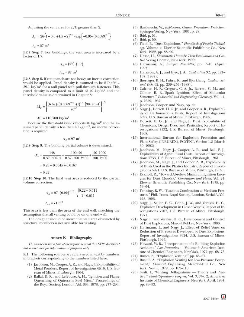
68–73ANNEX K
Adjusting the vent area for L/D greater than 2,
Av10 75 226 1 0 6 4 5 2 0 95 0 0689= + −( ) − ⋅ ( )⎡⎣ ⎤⎦ . . exp . ..⋅ ⋅
Av1 57= m 2
J.2.7 Step 7. For buildings, the vent area is increased by afactor of 1.7:
Av 2 57 1 7= ( ) ( )⋅ .
Av 2 97= m 2
J.2.8 Step 8. If vent panels are too heavy, an inertia correctionwould be applied. Panel density is assumed to be 8 lb/ft2 =39.1 kg/m2 for a wall panel with pull-through fasteners. Thispanel density is compared to a limit of 40 kg/m2 and thethreshold value as determined in Chapter 8:
MT = ( ) ( ) ( ) [ ]⎧⎨⎪
⎩⎪
⎫⎬⎪
⎭⎪
6 67 0 0689 1 30 20 480
0 2 0 3
0 5
1 67. . . .
.
.⋅ ⋅ ⋅ ⋅ ⋅
MT = 110 700, kg/m 2
Because the threshold value exceeds 40 kg/m2 and the as-sumed panel density is less than 40 kg/m2, no inertia correc-tion is required:
Av 3 97= m2
J.2.9 Step 9. The building partial volume is determined:
Xr = + +
= +
1480 37 500 4
100 200 37 500 2400
20 1000500 2400
0 20
. .
.
⋅ ⋅⋅
⋅ ⋅⋅⋅
00 0045 0 0167
0 22
. .
.
+
=J.2.10 Step 10. The final vent area is reduced by the partialvolume correction:
Av 41 397 0 22
0 22 0 0111 0 011
= ⋅ ( ) −−
−.. .
./ ⋅
Av 4 74= m 2
This area is less than the area of the end wall, matching theassumption that all venting could be on one end wall.
The designer should be aware that wall area obstructed bystructural members is not available for venting.
Annex K Bibliography
This annex is not a part of the requirements of this NFPA documentbut is included for informational purposes only.
K.1 The following sources are referenced in text by numbersin brackets corresponding to the numbers listed here.
(1) Jacobson, M., Cooper, A. R., and Nagy, J. Explosibility ofMetal Powders, Report of Investigations 6516, U.S. Bu-reau of Mines, Pittsburgh, 1964.
(2) Ballal, D. R., and Lefebure, A. H., “Ignition and FlameQuenching of Quiescent Fuel Mists,” Proceedings ofthe Royal Society, London, Vol. 364, 1978, pp. 277–294.
(3) Bartknecht, W., Explosions: Course, Prevention, Protection,Springer-Verlag, New York, 1981, p. 28.
(4) Ibid, p. 51.(5) Ibid, p. 50.(6) Field, P., “Dust Explosions,” Handbook of Powder Technol-
ogy, Volume 4; Elsevier Scientific Publishing Co., NewYork, 1982, pp. 88–90.
(7) Haase, H., Electrostatic Hazards: Their Evaluation and Con-trol, Verlag Chemie, New York, 1977.
(8) Harmanny, A., Europex Newsletter, pp. 7–10 (April,1993).
(9) Harrison, A. J., and Eyre, J. A., Combustion 32, pp. 121–137 (1987).
(10) Jhertager, B. H., Fuhre, K., and Bjorkhaug. Combus. Sci.and Tech. 62, pp. 239–256 (1988).
(11) Calcote, H. F., Gregory, C. A. Jr., Barrett, C. M., andGilmer, R. B.,“Spark Ignition, Effect of MolecularStructure,” Industrial and Engineering Chemistry, Vol. 44,p. 2659, 1952.
(12) Jacobson, Cooper, and Nagy, op. cit.(13) Nagy, J., Dorsett, H. G. Jr., and Cooper, A. R., Explosibil-
ity of Carbonaceous Dusts, Report of Investigations6597, U.S. Bureau of Mines, Pittsburgh, 1965.
(14) Dorsett, H. G., Jr., and Nagy, J., Dust Explosibility ofChemicals, Drugs, Dyes, and Pesticides, Report of In-vestigations 7132, U.S. Bureau of Mines, Pittsburgh,1968.
(15) International Bureau for Explosion Protection andPlant Safety (INBUREX), PCVENT, Version 1.2 (March30, 1993).
(16) Jacobson, M., Nagy, J., Cooper, A. R., and Ball, F. J.,Explosibility of Agricultural Dusts, Report of Investiga-tions 5753, U.S. Bureau of Mines, Pittsburgh, 1961.
(17) Jacobson, M., Nagy, J., and Cooper, A. R., Explosibilityof Dusts Used in the Plastics Industry, Report of Investi-gations 5971, U.S. Bureau of Mines, Pittsburgh, 1962.
(18) Eckhoff, R., “Toward Absolute Minimum Ignition Ener-gies for Dust Clouds?,” Combustion and Flame, Vol. 24,Elsevier Scientific Publishing Co., New York, 1975, pp.53–64.
(19) Fenning, R. W., “Gaseous Combustion at Medium Pres-sures,” Phil. Trans. Royal Society, London, Serial A, Vol.225, 1926.
(20) Nagy, J., Seiler, E. C., Conn, J. W., and Verakis, H. C.,Explosion Development in Closed Vessels, Report of In-vestigations 7507, U.S. Bureau of Mines, Pittsburgh,1971.
(21) Nagy, J., and Verakis, H. C., Development and Controlof Dust Explosions, Marcel Dekker, New York, 1983.
(22) Hartmann, I., and Nagy, J., Effect of Relief Vents onReduction of Pressures Developed by Dust Explosions,Report of Investigations 3924, U.S. Bureau of Mines,Pittsburgh, 1946.
(23) Howard, W. B., “Interpretation of a Building ExplosionAccident,” Loss Prevention — Volume 6; American Insti-tute of Chemical Engineers, New York, 1972, pp. 68–73.
(24) Runes, E., “Explosion Venting,” pp. 63–67.(25) Rust, E. A., “Explosion Venting for Low-Pressure Equip-
ment,” Chemical Engineering, McGraw-Hill Co., NewYork, Nov. 5, 1979, pp. 102–110.
(26) Swift, I., “Venting Deflagrations — Theory and Prac-tice,” Plant/Operations Progress, Vol. 3, No. 2, AmericanInstitute of Chemical Engineers, New York, April, 1984,pp. 89–93.
2007 Edition

68–74 EXPLOSION PROTECTION BY DEFLAGRATION VENTING
(27) Yao, C., “Explosion Venting of Low-Strength Equip-ment and Structures,” Loss Prevention — Volume 8;American Institute of Chemical Engineers, New York,1974, p. 109.
(28) Swift, I., and Epstein, M., “Performance of Low Pres-sure Explosion Vents,” Paper 84d, 20th Annual LossPrevention Symposium, AIChE Spring National Meet-ing, New Orleans, LA, April 6–10, 1986.
(29) Benson, R. S. and Burgoyne, J. H., British ShipbuildingResearch Assn., Report No. 76, 1951.
(30) Howard, W. B., and Karabinis, A. H., “Tests of ExplosionVenting of Buildings,” Plant/Operations Progress, Vol. 1,American Institute of Chemical Engineers, New York,January 1982, pp. 51–68.
(31) Zalosh, R. G., “Gas Explosion Tests in Room-SizeVented Enclosures,” Loss Prevention — Volume 13,American Institute of Chemical Engineers, New York,1980.
(32) Kommitten fur Explosions Forsok, Bromma 1957, Slutrap-port, Stockholm, April 1958.
(33) Tonkin, P. S., and Berlemont, C. F. J., “Dust Explosionsin a Large-Scale Cyclone Plant,” Fire Research Note No.942, Fire Research Station, Borehamwood, UK, July1972.
(34) Sapko, M. J., Furno, A. L., and Kuchta, J. M., Flame andPressure Development of Large-Scale CH 4-Air-N 2 Ex-plosions, Report of Investigations 8176, U.S. Bureau ofMines, Pittsburgh, PA, 1976.
(35) Harris, G. F. P. and Briscoe, P. G., “The Venting of Pen-tane Vapor-Air Explosions in a Large Vessel,” Combustionand Flame, Vol. 11, Aug. 1967, pp. 329–388.
(36) Cubbage, P. A., and Simmonds, W. A., “An Investigationof Explosion Reliefs for Industrial Drying Ovens,” GasCouncil Res. (London) Communications GC23, 1955.
(37) Thorne, P. F., Rogowski, Z. W., and Field, P., “Perfor-mance of Low Inertia Explosion Reliefs Fitted to a22 m3 Cubical Chamber,” 4th Int’l Symp. on Loss Pre-vention and Safety Promotion in the Process Industries,EFCE Publication Series, No. 33, Vol. 3, F1-F10, Sept.12–16, 1983.
(38) van Wingerden, C. J. M., and Zeeuwen, J. P., “Venting ofGas Explosions in Large Rooms,” 4th Int’l Symp. onLoss Prevention and Safety Promotion in the ProcessIndustries, EFCE Publication Series, No. 33, Vol. 3,F38–F47, Sept. 12–16, 1983.
(39) Yao, C., deRis, J., Bajpai, S. N., and Buckley, J. L., “Evalu-ation of Protection from Explosion Overpressure inAEC Gloveboxes,” Norwood, MA: Factory Mutual Re-search Corporation, FMRC Report 16215.1, Dec. 1969.
(40) Burgoyne, J. H., and Wilson, M. J. G., “The Relief ofPentane Vapor-Air Explosions in Vessels,” Symp. onChemical Process Hazards, IChemE (London), 1960,p. 25.
(41) Lunn, G. A. and Cairns, F., “The Venting of Dust Explo-sions in a Dust Collector,” J. Hazardous Materials, Vol. 12,1985, pp. 85–107.
(42) Zalosh, R. G., and Coll, J. P., “Explosion Venting TestProgram for Municipal Solid Waste Shredders,” pre-sented at 1981 Annual Meeting of Society of Fire Pro-tection Engineers, S.F.P.E. Seminar on EngineeringFire Safe Conservation and Resource Recovery, Dallas,Texas, May 18–21, 1981.
(43) Cooper, M. G., Fairweather, M., and Tite, J. P., “On theMechanisms of Pressure Generation in Vented Explo-sions,” Combustion and Flame, 65, pp. 1–14, 1986.
2007 Edition
(44) Solberg, D. M., Pappas, J. A., and Skramstad, E., “Obser-vations of Flame Instabilities in Large-Scale Vented GasExplosions,” 18th Symposium (Int’l) on Combustion,Combustion Institute, pp. 1607–1614, 1981.
(45) van Wingerden, C. J. M., and Zeeuwen, J. P., “FlameInstabilities in Vented Gas Explosions,” Combustion andFlame, 51, pp. 109–111, 1983.
(46) Faber, M., Recoil Forces of Vented Explosions in Techni-cal Installations, Europex Newsletter, Dec. 1991, pp. 2–3.
(47) Donat, C., “Application of Explosion Pressure Relief asa Protective Measure for Industrial Plant Equipment,”Loss Prevention — Volume 11, American Institute ofChemical Engineers, New York, 1977.
(48) Donat, C., “Release of the Pressure of an Explosion withRupture Discs and Explosion Valves,” ACHEMA 73,Frankfurt am Main, Republic of Germany, 1973.
(49) Donat, C., Staub-Reinhaltung der Luft, Vol. 31, No. 4,April, 1971, pp. 154–160.
(50) Bartknecht, W., and Kuhner, G., Forschungsbericht 45,Bundesinstitut fur Arbeitsschutz, 1971.
(51) Bartknecht, W., Explosions: Course, Prevention, Protection,Springer-Verlag, New York, 1981.
(52) Pineau, J., Giltaire, M., and Dangreaux, J., “Etuded’explosions de poussieres en recipients de 1, 10 et 100m3,” Note No. 1005-83-76, Cahier de Notes Documen-taires, No. 83, 2nd Trimestre, 1976.
(53) Simpson, L. L., “Equations for the VDI and BartknechtNomograms,” Plant/Operation Progress, Vol. 5, No. 1,American Institute of Chemical Engineers, New York,Jan. 1986, pp. 49–51.
(54) Siwek, R., and Skov, O., Verein Deutsche Ingenieure Ber-ichte, No. 701, Vol. 2, pp 569–616 (Düsseldorf; VDI-Verlag, 1988).
(55) Lee, J. H. S., and Guirao, C. M., “Pressure Developmentin Closed and Vented Vessels,” Plant/Operations Progress,Vol. 1, No. 2, American Institute of Chemical Engi-neers, April, 1982, pp. 75–85.
(56) Bartknecht, W., op. cit., pp. 18–23 and p. 124.(57) Ibid, pp. 7–26.(58) Ibid, p. 111.(59) Cousins, E. W., and Cotton, P. E., “The Protection of
Closed Vessels Against Internal Explosions,” AmericanSociety of Mechanical Engineers, Paper No. 51-PRI-2,1951.
(60) Maisey, H. R., “Gaseous and Dust Explosion Venting,”Chemical and Process Engineering, Vol. 46, Oct. 1965.
(61) Chippett, S., “An Investigation of Vented Explosions atInitially Elevated Pressures for Propane/Air Flames,”Report of Research Project conducted for NFPA Com-mittee on Explosion Protection Systems, Feb. 2, 1984.
(62) Burgoyne, J. H., and Cohen, L., Proceedings of theRoyal Society, Vol. 225, London, 1954, pp. 375–392.
(63) Browning, J. A., Tyler, T. L., and Drall, W. G., “Effectof Particle Size on Combustion of Uniform Suspen-sion,” Industrial and Engineering Chemistry, Vol. 49,1957, pp. 142–148.
(64) Vincent, G. C., and Howard, W. B., “Hydrocarbon MistExplosions — Part I: Prevention by Explosion Suppres-sion,” Loss Prevention — Volume 10, American Instituteof Chemical Engineers, New York, 1976, pp. 43–47.
(65) Zabetakis, M., Flammability Characteristics of Combus-tible Gases and Vapors, Bulletin 627, U.S. Bureau ofMines, Pittsburgh, 1965, pp. 6–7.

68–75ANNEX K
(66) VDI Richtlinie 3673, Pressure Release of Dust Explo-sions, Verein Deutscher Ingenieure-Kommission Rein-haltung der Luft, Düsseldorf, 1979 and 1983, VDI Ver-lag GmbH, Düsseldorf.
(67) Schwab, R. F., private communication.(68) Rasbash, D. J., and Rogowski, Z. W., “Gaseous Explo-
sions in Vented Ducts,” Combustion and Flame, Vol. 4, No.4, Butterworth, London, Dec. 1960, pp. 301–312.
(69) Rasbash, D. J., and Rogowski, Z. W., “Relief of Explo-sions in Propane/Air Mixtures Moving in a StraightUnobstructed Duct,” Second Symposium on ChemicalProcess Hazards with Special Reference to Plant De-sign, Institution of Chemical Engineers, London, 1963.
(70) Palmer, K. N., “Relief Venting of Dust Explosions inProcess Plant,” Symposium on Major Loss Preventionin the Process Industries, IChemE Symposium SeriesNo. 34, Institution of Chemical Engineers, London,1971.
(71) Palmer, K. N., Dust Explosions and Fires, Chapmanand Hall, London, 1973.
(72) Guide to the Use of Flame Arrestors and Explosion Re-liefs, Ministry of Labour, New Series No. 34, Her Majes-ty’s Stationery Office, London, 1965.
(73) Pineau, J. and Ronchail, G., “Propagation of Dust Ex-plosions in Ducts,” Proceedings of the Symposium onthe Control and Prevention of Dust Explosions, Basel,1982.
(74) Matsuda, T., Toyonaga, K., Nozima, Y., Kobayashi, M.,and Shimizu, T.,“Some Observations on Dust Ex-plosibility in a Pneumatic Transport System,” Journalof Powder and Bulk Solids Technology, Vol. 6, No. 4,1982, pp. 22–28.
(75) Bjorklund, R. A., and Ryason, P. R., Detonation Flame Ar-restor Devices for Gasoline Cargo Vapor Recovery Systems, Pub-lication 80–18, Jet Propulsion Laboratories, Pasadena,1980.
(76) Palmer, K. N., “Explosion Protection of a Dust Extrac-tion System,” Institution of Chemical Engineers, Sym-posium Series 39, April, 1974.
(77) Britton, L. G., and Chippett, S., “Practical Aspects ofDust Deflagration Testing,” Paper 58d, 17th AnnualLoss Prevention Symposium, American Institute ofChemical Engineers, Houston, March 24–28, 1985.
(78) Swift, I., “Gaseous Combustion Venting — a SimplifiedApproach,” The Institution of Chemical EngineersSymposium Series 82, 4th International Symposium onLoss Prevention and Safety Promotion in the ProcessIndustries, Volume 3 — Chemical Process Hazards(1983).
(79) Chippett, S., “Modeling Vented Explosions,” Combus-tion and Flame, Elsevier Scientific Publishing Co., Vol-ume 55, No. 1 (1984).
(80) Swift, I., “Developments in Dust Explosibility Testing:The Effect of Test Variables,” Proceedings of the Inter-national Specialists Meeting on Fuel-Air Explosions,McGill University, Montreal, Nov. 4–6 (1981), edited byJ. H. S. Lee and C. M. Guirao, University of WaterlooPress (1982).
(81) Cocks, R. E., and Meyer, R. C., “Fabrication and Use ofa 20 Liter Spherical Dust Testing Apparatus,” Loss Pre-vention — Volume 14, American Institute of ChemicalEngineers (1981).
(82) NACA Report 1300, National Advisory Committee onAeronautics, 1959, Tables 31-32.
(83) Perry, R. H., and Chilton, C. H. (Eds.), Chemical Engi-neers’ Handbook, 5th Edition, McGraw-Hill, New York,1973.
(84) Andrews, G. E., and Bradley, D., “Determination ofBurning Velocities: A Critical Review,” Combustion andFlame, Vol. 18, Elsevier Scientific Publishing Co., NewYork, 1972, pp. 133–153.
(85) France, D. H., and Pritchard, R., “Burning VelocityMeasurements of Multicomponent Fuel Gas Mixtures,”Gas Warme International, Vol. 26, No. 12, 1977.
(86) Forschungsbericht Staubexplosionen: Brenn- undExplosions-Kenngrossen von Stauben, Hauptverbandder gewerblichen Berufsgenossenschaften e.V., Bonn,1980.
(87) Zalosh, R. G., and Coll, J. P., “Explosion Venting TestProgram for Municipal Solid Waste Shredders,” SFPETechnology Report 81-9, Society of Fire Protection En-gineers, Boston, MA, April, 1981.
(88) Bartknecht, W., “Pressure Venting of Dust Explosions inLarge Vessels,” Paper 82f, 20th Annual Loss PreventionSymposium, AIChE Spring National Meeting, New Or-leans, LA, April 6–10, 1986.
(89) Bartknecht, W., “Effectiveness of Explosion Venting as aProtective Measure for Silos,” Plant/Operation Progress,Vol. 4, No. 1, American Institute of Chemical Engi-neers, New York, Jan. 1985, pp. 4–13.
(90) Britton, L. G., “Measurement of Minimum Ignition En-ergy for Safety Application,” Paper 70f, 25th AnnualLoss Prevention Symposium, AIChE Summer NationalMeeting, Pittsburgh, PA, August 19–22, 1991.
(91) Howard W. B., private communication.(92) Britton: 1992 — Plant Operations Progress (Vol. 11, No.
2), April 1992.(93) Lunn, G. A., Guide to Dust Explosion Prevention and
Protection, Part 3, “Venting of Weak Explosions and theEffects of Vent Ducts,” The Institution of Chemical En-gineers, British Materials Handling Board, London,England, 1988.
(94) Bartknecht, W., Dust Explosions, Course, Prevention, Protec-tion, Springer-Verlag, Berlin, Germany, 1989.
(95) DeGood, R., and Chatrathi, K., “Comparative Analysisof Test Work Studying Factors Influencing PressuresDeveloped in Vented Deflagration,” Journal of Loss Pre-vention Process Industries, Vol 4, Oct. 1991.
(96) ASTM E 1226-88, Standard Test Method for Pressure andRate of Pressure Rise for Combustible Dusts.
(97) Cashdollar, Kenneth L., and Chatrathi, K., “MinimumExplosible Dust Concentrations Measured in 20-L andl-m3 Chambers,” Combustion Science and Technology,1992, Vol. 87, pp. 157–171.
(98) Cashdollar, K. L., and Hertzberg, M., editors, “Indus-trial Dust Explosions,” ASTM Publications STP 958,1987.
(99) Bartknecht, W., Dust Explosions: Course, Prevention, andProtection, Springer-Verlag, 1989.
(100) Eckhoff, R. K., Dust Explosions in the Process Industries,Butterworth-Heinemann, Oxford, 1991.
(101) Bartknecht, W., “Explosions-Schutz: Grundlagen undAnwendung,” Springer-Verlag, 1993. (German only)
(102) Zalosh, R. G., and Chaffee, J. L., “Partial Volume andWall Effects in Vented Gas Explosions,” Canadian Con-ference on Chemical Engr, July 1990.
(103) Taminini, F., and Chaffee, J. L., “Turbulent Vented GasExplosions with and without Acoustically Induced In-stabilities,” Proceedings, Twenty-Fourth International
2007 Edition

68–76 EXPLOSION PROTECTION BY DEFLAGRATION VENTING
Symposium on Combustion, pp. 1845–51, The Com-bustion Institute, 1992.
(104) VDI 3673, “Pressure Venting of Dust Explosions,” VereinDeutscher Ingenieure — Kommission Reinhaltung derLuft, Düsseldorf, VDI Verlag GmbH, Düsseldorf, 1995.
(105) Vogl, A., “The Course of Dust Explosions in Pipes ofPneumatic Systems,” Symposium “Esplosioni da pol-veri: valutazione, prevenzione e protezione,” San Do-nato Milanese, Milan, Italy, June 28, 1995.
(106) Proust, Ch., “Dust Explosions in Pipes: A Review,” Jour-nal of Loss Prevention Process Industries, Elsevier ScienceLtd., Great Britain, U.K., Vol. 9, No. 4, pp. 267–277,1996.
(107) Siwek, R., and Scov, O., “Model Calculation for Deter-mining the Dimensions of Hinged Vents on the Basis ofRealistic Explosion Tests,” (Modellberechnung zur Di-mensionierung von Explosionsklappen auf der Basisvon praxisnahen Explosionsversuchen.) VDI Berichte,No. 701, pp. 569–616, 1988.
(108) Crowhurst, D., Colwell, S. A., and Hoare, D. P., “TheExternal Explosion Characteristics of Vented Dust Ex-plosions,” IChemE Symposium Series, No. 139, 1995.
(109) Cashdollar, K. L., and Hertzberg, M., “Laboratory Studyof Rock Dust Inerting Requirements: Effects of CoalVolatility, Particle Size and Methane Addition,” 23rd In-ternational Conference of Safety in Mines Research In-stitutes, Washington D.C., Sept. 1989.
(110) Senecal, J. A., and Beaulieu, P. A., “KG: Data and Analy-sis,” 31st Loss Prevention Symposium, AIChE SpringNational Meeting, Houston, TX, March 1997.
(111) FM Test Report, J.I 1X1A8.AF, Class 773, Norwood, MA:1997.
(112) Lunn, G.A., P. Holbrow, and D. E. Brookes. 1999. TheEffects of Bursting Discs on the Reduced Pressure from VentedDust Explosions, TD/99/04.
(113) Holobrow, P., Hawksworth, S., Tyldesley, A., ThermalRadiation from Vented Dust Explosions, Journal of LossPrevention in the Process Industries, Volume 13, No. 6, pp.467–476.
(114) Task Group report “NFPA 68 Impulse Task Force Re-port to the Committee on Explosion Protection Sys-tems, September 15, 1999”
(115) Ural, E. A. 2005. “Dust Explosion Venting throughDucts.” Proc. 39th Annual Loss Prevention Symp.,American Institute of Chemical Engineers, Atlanta, GA,April 10–14.
(116) Health and Safety Laboratory, Harpur Hill, Bruxton,UK, final report, “Effect of Deflector Plates on VentedDust Explosions,” EC/98/29, dated 20 November,1998.
(117) T. Forcier, R. Zalosh, “External Pressures Generated byVented Gas and Dust Explosions,” J. of Loss Preventionin the Process Industries, v. 13, pp. 411-417, 2000.
(118) Communication from D. Herrmann to Committee onExplosion Protection Systems, May 2005.
(119) Task Group report “Zalosh — Larger Vent Area Option3, Draft 2.”
(120) Zalosh, R. G., “New Dust Explosion Venting Design Re-quirements for Turbulent Operating Conditions,” pre-sented at 6th International Symposium on the Preven-tion and Mitigation of Industrial Explosions, Halifax,Nova Scotia, August 2006.
2007 Edition
Annex L Informational References
L.1 Referenced Publications. The documents or portionsthereof listed in this annex are referenced within the informa-tional sections of this standard and are not part of the require-ments of this document unless also listed in Chapter 2 forother reasons.
L.1.1 NFPA Publications. National Fire Protection Associa-tion, 1 Batterymarch Park, Quincy, MA 02169-7471.
NFPA 30, Flammable and Combustible Liquids Code, 2003 edi-tion.
NFPA 30B, Code for the Manufacture and Storage of Aerosol Prod-ucts, 2007 edition.
NFPA 33, Standard for Spray Application Using Flammable orCombustible Materials, 2007 edition.
NFPA 35, Standard for the Manufacture of Organic Coatings,2005 edition.
NFPA 52, Vehicular Fuel Systems Code, 2006 edition.NFPA 61, Standard for the Prevention of Fires and Dust Explo-
sions in Agricultural and Food Processing Facilities, 2002 edition.NFPA 69, Standard on Explosion Prevention Systems, 2002 edi-
tion.NFPA 432, Code for the Storage of Organic Peroxide Formulations,
2002 edition.NFPA 484, Standard for Combustible Metals, 2006 edition.NFPA 654, Standard for the Prevention of Fire and Dust Explo-
sions from the Manufacturing, Processing, and Handling of Combus-tible Particulate Solids, 2006 edition.
NFPA 750, Standard on Water Mist Fire Protection Systems, 2006edition.
Fire Protection Guide to Hazardous Materials, 2001 edition.
L.1.2 Other Publications.
L.1.2.1 ANSI Publications. American National Standards In-stitute, Inc., 25 West 43rd Street, 4th Floor, New York, NY10036.
ANSI Z535, Product Safety Signs and Labels, 1998.
L.1.2.2 API Publications. American Petroleum Institute, 1220L. Street, N.W., Washington, DC 20005-4070.
API 752, Management of Hazards Associated with Location ofProcess Plant Buildings, 2003.
L.1.2.3 ASTM Publications. ASTM International, 100 BarrHarbor Drive, P.O. Box C700, West Conshohocken, PA 19428-2959.
ASTM D 5680a, Standard Practice for Sampling UnconsolidatedSolids in Drums or Similar Containers, 2001.
ASTM E 502, Standard Test Method for Selection and Use ofASTM Standards for the Determination of Flash Point of Chemicals byClosed Cup Methods, 2000.
ASTM E 582, Standard Test Method for Minimum Ignition En-ergy and Quenching Distance in Gaseous Mixtures, 2004.
ASTM E 681, Standard Test Method for Concentration Limits ofFlammability of Chemicals (Vapors and Gases), 2004.
ASTM E 1226, Standard Test Method for Pressure and Rate ofPressure Rise for Combustible Dusts, 1994.
ASTM E 1515, Standard Test Method for Minimum ExplosibleConcentration of Combustible Dusts, 1998.

68–77ANNEX L
ASTM E 2019, Standard Test Method for Minimum IgnitionEnergy of a Dust Cloud in Air, 2003.
L.1.2.4 CCPS Publications. Center for Chemical ProcessSafety, 3 Park Avenue, 19th Floor, New York, NY 10016.
Guidelines for Safe Handling of Powders and Bulk Solids, 2004.
L.1.2.5 ISO Publications. International Organization forStandardization, 1, rue de Varembé, Case postale 56, CH-1211Geneve 20, Switzerland.
ISO 6184/1, Explosion Protection Systems — Part 1: Determina-tion of Explosion Indices of Combustible Dust in Air, 1985.
L.1.2.6 NACE Publications. NACE International, 1440 SouthCreek Drive, Houston, TX 77084-4906.
National Association of Corrosion Engineers Handbook, 2nd edi-tion, 1991.
L.1.2.7 U.S. Government Publications. U.S. GovernmentPrinting Office, Washington, DC 20402.
TM5-1300, Stucture to Resist the Effects of Accidental Explosions,Department of Defense Explosives Safety Board, 1990.
L.1.2.8 Other Publications.Biggs, J.M. 1964. Introduction to Structural Dynamics, McGraw-
Hill.Darby, Ron, Chemical Engineering Fluid Mechanics, 2nd Edi-
tion, Marcel Dekker, Inc. 2001.Lees, F.P., Lees Loss Prevention in the Process Industries, 2nd
Edition, Butterworth–Heinemann, 1996.Krishna, Kiran; Rogers, William; Mannan, M. Sam, The use
of aerosol formation, flammability, and explosion informationfor heat-transfer fluid selection, Journal of Hazardous Materials104, 2003.
L.2 Informational References. (Reserved)
L.3 References for Extracts in Informational Sections.(Reserved)
2007 Edition

68–78 EXPLOSION PROTECTION BY DEFLAGRATION VENTING
Index
Copyright © 2007 National Fire Protection Association. All Rights Reserved.
The copyright in this index is separate and distinct from the copyright in the document that it indexes. The licensing provisions set forth for thedocument are not applicable to this index. This index may not be reproduced in whole or in part by any means without the express written
permission of NFPA.-A-Access, deflagration discharge spaces . . . . . . . . . . . . . . . . 5.2.3.3, A.5.2.3.3Acoustic flame instabilities . . . . . . . . . . . . . . . . . . . . . . . . . . . . . . . . . . . . . . . A.6.4.4Agricultural products, deflagration characteristics . . . . . . . Table F.1(a)Air intakes, location in relation to deflagration vents . . . . . . . . . . 6.6.2.1Alternative vent area methodology . . . . . . . . . . . . . . . . . . . . . . . . . . . . Annex HApplication of standard . . . . . . . . . . . . . . . . . . . . . . . . . . . . . . . . . . . . . . . . 1.3, A.1.3Approved (definition) . . . . . . . . . . . . . . . . . . . . . . . . . . . . . . . . . . . . . . 3.2.1, A.3.2.1Authority having jurisdiction (definition) . . . . . . . . . . . . . . . . 3.2.2, A.3.2.2
-B-Bibliography . . . . . . . . . . . . . . . . . . . . . . . . . . . . . . . . . . . . . . . . . . . . . . . . . . . . . Annex KBins, deflagration venting for . . . . 8.2.3.1, 8.6, A.8.2.3.1, A.8.6.1, A.8.6.3Burning velocity . . . . . . . . . . . . . . . 7.2.2.2, 9.2.11, 9.2.12, A.7.2.2.2, B.1.2.5
Definition . . . . . . . . . . . . . . . . . . . . . . . . . . . . . . . . . . . . . . . . . . . . . . . . . . . . . . . . . . 3.3.1Fundamental . . . . . . . . . . . . . . . . . . . . . . . . . . . . . 6.1.3.1, B.1.2.5.1, B.1.2.5.2
Definition . . . . . . . . . . . . . . . . . . . . . . . . . . . . . . . . . . . . . . . . . . . . . . . . . . . . . 3.3.1.1Flammable gases in air, selected . . . . . . . . . . . . . . . . . . . . . . . . . Annex DVent size based on . . . . . . . . . . . . . . . . . . . . . . . . . . . . . . . . . . . . . . . . . . . . . . 6.2.1
-C-Carbonaceous dusts, deflagration characteristics . . . . . . . . Table F.1(b)Change, management of . . . . . . . . . . . . . . . . . . . . . . . . . . . . . . . . . . . 11.8, A.11.8.2Chemical dusts, deflagration characteristics . . . . . . . . . . . . . . Table F.1(c)Closures, vent . . . . . . . . . . . . . . . . . . . . . . . . . . . . . . . . . . . . . . . . . . . .see Vent closuresCombustible dust (definition) . . . . . . . . . . . . . . . . . . . . . . . 3.3.2; see also DustCombustible gas . . . . . . . . . . . . . . . . . . . . . . . . . . . . . . . . . . . . . . . . . . . . . . . . . . . .see GasCombustible liquids
Foams of combustible liquids, deflagrationventing for . . . . . . . . . . . . . . . . . . . . . . . . . . . . . . . . . . . . 6.2.4, A.6.2.4
In mists . . . . . . . . . . . . . . . . . . . . . . . . . . . . . . . . . . . . . . . . . . . . . . . . . . . . . . . . . .see MistsCombustion (definition) . . . . . . . . . . . . . . . . . . . . . . . . . . . . . . . . . . . . . . . . . . . . 3.3.3Cones . . . . . . . . . . . . . . . . . . . . . . . . . . . . .see Hoppers, deflagration venting forConversion factors . . . . . . . . . . . . . . . . . . . . . . . . . . . . . . . . . . . . . . . . . . . . . . . . . . . . . 1.6
-D-Definitions . . . . . . . . . . . . . . . . . . . . . . . . . . . . . . . . . . . . . . . . . . . . . . . . . . . . . . . . Chap. 3Deflagration
CharacteristicsCombustible dusts, selected . . . . . . . Tables F.1(a) to (e), Annex FFlammable gases, selected . . . . . . . . . . . . . . . . . . . . Table E.1, Annex E
Consequences of . . . . . . . . . . . . . . . . . . . . . . . . . . . . . . . . . . . . . . . . . . . . . 6.6, A.6.6Definition . . . . . . . . . . . . . . . . . . . . . . . . . . . . . . . . . . . . . . . . . . . . . . . . . . . . . . . . . . 3.3.4Requirements . . . . . . . . . . . . . . . . . . . . . . . . . . . . . . . . . . . . . . . . . . . . . . . . . . . . . B.1.1
Deflagration fundamentals . . . . . . . . . . . . . . . . . . . . . . . . . . . . . . . . . . . . . Annex BBurning velocity and flame speed . . . . . . . . . . . . . . . . . . . . . . . . . . . . . B.1.2.5Fuels
Combustible dust . . . . . . . . . . . . . . . . . . . . . . . . . . . . . . . . . . . . . . . . . . . . . . B.2.4Flammable gas . . . . . . . . . . . . . . . . . . . . . . . . . . . . . . . . . . . . . . . . . . . . . . . . . B.2.3Hybrid mixture . . . . . . . . . . . . . . . . . . . . . . . . . . . . . . . . . . . . . . . . . . . . . . . . B.2.5Mist . . . . . . . . . . . . . . . . . . . . . . . . . . . . . . . . . . . . . . . . . . . . . . . . . . . . . . . . . . . . . . B.2.6
Ignition sources . . . . . . . . . . . . . . . . . . . . . . . . . . . . . . . . . . . . . . . . . . . . . . . . . . . . . B.5Inert material . . . . . . . . . . . . . . . . . . . . . . . . . . . . . . . . . . . . . . . . . . . . . . . . . . . . . . . . B.4Initial temperature and pressure . . . . . . . . . . . . . . . . . . . . . . . . . . . . . . . . . . B.6Oxidant . . . . . . . . . . . . . . . . . . . . . . . . . . . . . . . . . . . . . . . . . . . . . . . . . . . . . . . . . . . . . . B.3Turbulence, effect of . . . . . . . . . . . . . . . . . . . . . . . . . . . . . . . . . . . . . . . . . . . . . . . B.7
Deflagration indexes . . . . . . . . . . . . . . . . . . . . . . . . . . . . . . . . . . . . . . .see also KG ; KStDefining equation . . . . . . . . . . . . . . . . . . . . . . . . . . . . . . . . . . . . . . . 6.1.1, A.6.1.1Definition . . . . . . . . . . . . . . . . . . . . . . . . . . . . . . . . . . . . . . . . . . . . . . . . . . . . . . . . . . 3.3.5Dusts and gases . . . . . . . . . . . . . . . . . . . . . . . . . . . . . . . . . . . . . . . . . . . . . . . Annex C
2007 Edition
Deflagration pressure . . . . . . . . . . . . . . . . . . . . . . . . . . . . . . . . . . . . .see Pressure (P)Deflagration vent closures . . . . . . . . . . . . . . . . . . . . . . . . . . . . . .see Vent closuresDeflagration venting/vents . . . . . . . . . . . . . . . . . . . . . . . . . . . .see Venting/ventsDeflectors . . . . . . . . . . . . . . . . . . . . . . 6.6.2.3 to 6.6.2.5, A.6.6.2.3 to A.6.6.2.5Detonation
Definition . . . . . . . . . . . . . . . . . . . . . . . . . . . . . . . . . . . . . . . . . . . . . . . . . . . . . . . . . . 3.3.6Transition to, preventing . . . . . . . . . . . . . . . . . . . . . . . . . . . . . . 9.2.9, A.9.2.9.2
dP/dt . . . . . . . . . . . . . . . . . . . . . . . . . . . . . . . . . . . . .see Rate of pressure rise (dP/dt)Dryers . . . . . . . . . . . . . . . . . . . . . . . . . . . . . . . . . . . . . . . 8.3.3, A.8.3.3, A.9.2.10.2.2.1Ducts
Deflagration vent discharge ducts . . . . . . . . . . . . . . . . . . . . . . . . 6.8, A.6.8.3Dusts and hybrid mixtures, venting of
deflagrations of . . . . . . . . . . . . . . . . . . . . . . . 7.4, 8.5, A.7.4, A.8.5Gas mixtures or mists, venting of . . . . . . . . . . . . . . . . . . . . . . . . 7.4, A.7.4
Venting of deflagrations in ducts . . . . .see Pipes and ducts operatingat or near atmospheric pressure
Dust collectors using bags, filters, or cartridges,venting of . . . . . . . . . . . . . . . . . . . . . . . . . . . . . . . . . . . . . 6.4.3.3.1, 8.7
Dusts . . . . . . . . . . . . . . . . . . . . . . . . . . . . . . . . . . . . . . . . . . . . . . . . . . . . . . . . . . . . . . . . . . B.2.1Accumulation . . . . . . . . . . . . . . . . . . . . . . . . . . . . . . . . . . . . . . . . . . . . . . . . . . . B.2.4.5Combustible (definition) . . . . . . . . . . . . . . . . . . . . . . . . . . . . . . . . . . . . . . . . . 3.3.2Concentration . . . . . . . . . . . . . . . . . . . . . . . . . . . . . . . . . . . . . . . . . . . . . . . . . . . . . B.2.2Definition . . . . . . . . . . . . . . . . . . . . . . . . . . . . . . . . . . . . . . . . . . . . . . . . . . . . . . . . . . 3.3.7Deflagration characteristics of selected dusts . . . . . . . . . . . . . . Annex FDeflagration fundamentals . . . . . . . . . . . . . . . . . . . . . . . . . . . . . . . . . . . . . . B.2.4Deflagration index . . . . . . . . . . . . . . . . . . . . . . . . . . . . . . . . . . . . . . . . . . . . . . . .see KSt
Deflagration venting . . . . .see Dusts and hybrid mixtures, venting ofdeflagrations of
Fireball from . . . . . . . . . . . . . . . . . . . . . . . . . . . . . . . . . . . . . . . . . . . . . . . . . . . . . . A.6.6Flame propagation . . . . . . . . . . . . . . . . . . . . . . . . . . . . . . . . . . . . . . . . . . . . . B.2.4.3Hazard classes . . . . . . . . . . . . . . . . . . . . . . . . . . . . . . . . . . . . . . . . . . . . . . . . . . . B.1.2.4
Noncombustible, classification as . . . . . . . . . . . . . . . . . . . . . . . . . . . . . . C.6In hybrid mixture . . . . . . . . . . . . . . . . . . . . . . . . . . . . . . . . .see Hybrid mixturesInert powder, effect of . . . . . . . . . . . . . . . . . . . . . . . . . . . . . . . . . . . . . . . . . . . . B.4.2Moisture content . . . . . . . . . . . . . . . . . . . . . . . . . . . . . . . . . . . . 6.1.2.2, A.6.1.2.2Noncombustible, classification as . . . . . . . . . . . . . . . . . . . . . . . . . . . . . . . . . C.6Particle size . . . . . . 6.1.2.2, 8.1.2.1, A.6.1.2.2, B.2.4.1, B.2.4.2, B.2.4.7Testing . . . . . . . . . . . . . . . . . . . . . . . . . . . . . . . . . . . . . . . . . . . . . . . . . . . . . . . . . . . . . . . C.5
Dusts and hybrid mixtures, venting ofdeflagrations of . . . . . . . . . . . . . . . . . . . . . . . . . . . . . 6.2.2, Chap. 8
Bins, hoppers, and silos . . . . . . . . . 6.4.1, 6.4.3.6.1, 6.4.3.6.2, 7.3.3.1.2,8.2.3.1, 8.6, A.6.4.3, A.8.2.3.1, A.8.6.1, A.8.6.3
Discharge ducts, effect of . . . . . . . . . . . . . . . . . . . . . . . . . . . . . . . . . . . . 7.4, A.7.4Dust collectors using bags, filters, or cartridges . . . . . . . . . . . . . . . . . . 8.7Enclosures interconnected with pipelines . . . . . . . . . . . . . . 8.10, A.8.10Flame arresting and particulate retention, venting internal to
building with . . . . . . . . . . . . . . . . . . . . . . . . . . . . . . . . . . . . . 8.9, A.8.9Initially elevated pressure, effects of . . . . . . . . . . . . . . . . . . . . . . . . . . . . . . . 8.4Low inertia vent closures, venting
by means of . . . . . . . . . . . . . . . . . . . . . . . 8.2, A.8.2.2.2 to A.8.2.8Partial volume, effects of . . . . . . . . . . . . . . . . . . . . . . . . . . . . . . . . . . . . 8.3, A.8.3
Building partial volumes . . . . . . . . . . . . . . . . . . . . . . . . . . . . . 8.3.4, A.8.3.4Process equipment partial volumes . . . . . . . . . . . . . . . . . 8.3.3, A.8.3.3
System flow velocity 2m/sec or less . . . . . . . 9.2.10.2.2, A.9.2.10.2.2.1System flow velocity greater than 2 m/sec . . . . . . . . . . . . . . . . . . . . . 9.2.11System flow velocity greater than 20 m/sec or gases having
burning velocities more than 1.3 times thatof propane, or dusts with KSt >300 . . . . . . . . . . . . . . . . . 9.2.12
Vent ducts, effects of . . . . . . . . . . . . . . . . . . . . . . . . . . . . . . . . . . . . . . . . . 8.5, A.8.5Vent size . . . . . . . . . . . . . . . . . . . . . . . . . . . . . . . . . . . . . . . . . . . . 6.2.2, 6.2.3, A.6.2.3
Dynamic load factor (DLF) . . . . . . . . . . . 6.3.2, 6.3.5.1 to 6.3.5.3, A.6.3.2,A.6.3.5.1 to A.6.3.5.3, A.6.3.5.6

68–79INDEX
-E-Elongated enclosures . . . . . . . . . . . . . . . . 7.2.3, A.7.2.3, B.7.3; see also DuctsElongated vessels . . . . . . . . . . . . . . . . . . . . . . . . . . . . . . . . . . . . . . . . . . . . . . . . . . . . . 9.1.2Enclosures
Appurtenances . . . . . . . . . . . . . . . . . . . . . . . . . . . . . . . . . . . . . . . . . . . . . . . 7.5, A.7.5Within buildings . . . . . . . . . . . . . . . . . . . . . . . . . . . . . . . . . . 6.8.1, 7.4.5, A.7.4.5Consequences of deflagration in . . . . . . . . . . . . . . . . . . . . . . . . . . . 6.6, A.6.6Definition . . . . . . . . . . . . . . . . . . . . . . . . . . . . . . . . . . . . . . . . . . . . . . . . . 3.3.8, A.3.3.8Design and support . . . . . . . . . . . . . . . . . . . . . . . . 6.3, A.6.3.1.1 to A.6.3.5.6Elongated, length/diameter of . . . . . . . . . . . . . . . . . . . . . . . . . . . . . . . . . . 6.4.3Ignition sources
Location within enclosure, effect of . . . . . . . . . . . . . . . . . . . . . . . . . B.5.3Movement between enclosures . . . . . . . . . . . . . . . . . . . . . . . . . . . . . . . B.5.2
Interconnected . . . . . . . . . . . . . . . . . . . . . . . . . . . . . . . . . . . . . . . . . . . . 8.10, A.8.10Length-to-diameter ratio and vent variables . . . . . . . . . . . . . . . 6.4, A.6.4Openings . . . . . . . . . . . . . . . . . . . . . . . . . . . . . . . . . . . . . . . . . . . . . . . . . . . . . . . . 6.3.3.4Relieving walls or roof . . . . . . . . . . . . . . . . . . . . . . . . . . . . 6.3.4, 8.6.3, A.8.6.3Strength . . . . . . . . . . . . . . . . . . . . . . . . . . . . . . . . . . . . . . . . . . . . . . . . . . . . .see StrengthTurbulence, effect of . . . . . . . . . . . . . . . . . . . . . . . . . . . . . . . . . . .see TurbulenceVacuums within . . . . . . . . . . . . . . . . . . . . . . . . . . . . . . . . . . . . . . . . . . . . . . . . . . . . 6.5.1Vents for . . . . . . . . . . . . . . . . . . . . . . . . . . . . . . . . . . . . . . . . . . . . . .see Venting/ventsWall linings for . . . . . . . . . . . . . . . . . . . . . . . . . . . . . . . . . . . . . . . . . . . . . . . . . . A.6.4.4
Equivalency to standard . . . . . . . . . . . . . . . . . . . . . . . . . . . . . . . . . . . . . . . . . . . . . . . 1.4Equivalent diameter . . . . . . . . . . . . . . . . . . . . . . . . . . . . . .see Hydraulic diameterExplosion (definition) . . . . . . . . . . . . . . . . . . . . . . . . . . . . . . . . . . . . . . . . . . . . . . 3.3.10
-F-Fireball . . . . . . . . . . . . . . . . . . . . . . . . . . . . . . . . . . . . . . . . . . . . . . . . . 11.2, 11.4.4, A.6.6
Bins, hoppers, and silos . . . . . . . . . . . . . . . . . . . . . . . . . . . . . . . . . . . . . . . . 8.6.1.5Dimensions of . . . . . . . . . . . . . . . . . . . . . . . . . . . . . . . . 7.6.4, 8.8, A.7.6.4, A.8.8
Flame arresting vent systems . . . . . . . . . . . . . . . . . . . . . . 6.9, 8.9, 10.6, 11.4.4,A.6.9.1 to A.6.9.4, A.8.9, A.10.6
Flame propagation mechanism, combustible dust . . . . . . . . . . . . . . B.2.4.3Flame speed . . . . . . . . . . . . . . . . . . . . . . . . . . . . . . . . . . . . . . . . . . . . . . . . . . . . . . . . B.1.2.5
Definition . . . . . . . . . . . . . . . . . . . . . . . . . . . . . . . . . . . . . . . . . . . . . . 3.3.11, A.3.3.11Turbulence, effect of . . . . . . . . . . . . . . . . . . . . . . . . . . . . . . . . . . . . . . . . . . . . . B.7.1
Flammable gas . . . . . . . . . . . . . . . . . . . . . . . . . . . . . . . . . . . . . . . . . . . . . . . . . . . . . .see GasFlammable limits
Definition . . . . . . . . . . . . . . . . . . . . . . . . . . . . . . . . . . . . . . . . . . . . . . . . . . . . . . . . . 3.3.12Lower flammable limit (LFL)
Combustible dust . . . . . . . . . . . . . . . . . . . . . . . . . . . . . . . . . . . . . . . . . . . . B.2.4.4Definition . . . . . . . . . . . . . . . . . . . . . . . . . . . . . . . . . . . . . . . 3.3.12.1, A.3.3.12.1Flammable gas . . . . . . . . . . . . . . . . . . . . . . . . . . . . . . . . . . . . . . . . . . . . . . . B.2.3.1Hybrid mixture . . . . . . . . . . . . . . . . . . . . . . . . . . . . . . . . . . . . . . . . . . . . . . B.2.5.1Mists . . . . . . . . . . . . . . . . . . . . . . . . . . . . . . . . . . . . . . . . . . . . . . . . . . . . . . . . . . . . . B.2.6
Upper flammable limit (UFL)Combustible dusts . . . . . . . . . . . . . . . . . . . . . . . . . . . . . . . . . . . . . . . . . . . B.2.4.6Definition . . . . . . . . . . . . . . . . . . . . . . . . . . . . . . . . . . . . . . . . . . . . . . . . . . . 3.3.12.2Flammable gas . . . . . . . . . . . . . . . . . . . . . . . . . . . . . . . . . . . . . . . . . . . . . . . B.2.3.1
Flammable liquids in mists . . . . . . . . . . . . . . . . . . . . . . . . . . . . . . . . . . . . . . .see MistsFlammable range (definition) . . . . . . . . . . . . . . . . . . . . . . . . . . . . . . . . . . . . . 3.3.13Flash point
Definition . . . . . . . . . . . . . . . . . . . . . . . . . . . . . . . . . . . . . . . . . . . . . . 3.3.14, A.3.3.14Mists, ignition of . . . . . . . . . . . . . . . . . . . . . . . . . . . . . . . . . . . . . . . . . . . . . . . . . . B.2.6
Fluidized bed dryers . . . . . . . . . . . . . . . . . . . . . . . . . . . . . . . . . . . . . . . . . . . . . . . 8.3.3.3Foams of combustible liquids, deflagration of . . . . . . . . . . 6.2.4, A.6.2.4Fog . . . . . . . . . . . . . . . . . . . . . . . . . . . . . . . . . . . . . . . . . . . . . . . . . . . . . . . . . . . . . . . . . .see MistsFriction factor (fD) (definition) . . . . . . . . . . . . . . . . . . . . . . . . . 3.3.15, A.3.3.15Fuel . . . . . . . . . . . . . . . . . . . . . . . . . .see also Dusts; Gas; Hybrid mixtures; Mists
Concentration . . . . . . . . . . . . . . . . . . . . . . . . . . . B.1.1, B.1.2.2, B.1.2.3, B.2.2General . . . . . . . . . . . . . . . . . . . . . . . . . . . . . . . . . . . . . . . . . . . . . . . . . . . . . . . . . . . . B.2.1
Fundamental burning velocity . . . . . . . . . . . . . . . . . . . . . .see Burning velocity
-G-Gas . . . . . . . . . . . . . . . . . . . . . . . . . . . . . . . . . . . . . . . . . . . . . . . . . . . . . . . . . . . . . . . . . . . . B.2.1
Classification as noncombustible . . . . . . . . . . . . . . . . . . . . . . . . . . . . . . . . . . C.6Concentration of gaseous fuel . . . . . . . . . . . . . . . . . . . . . . . . . B.2.2, B.2.3.1Definition . . . . . . . . . . . . . . . . . . . . . . . . . . . . . . . . . . . . . . . . . . . . . . . . . . . . . . . . . 3.3.17Deflagration characteristics of selected
flammable gases . . . . . . . . . . . . . . . . . . . . . . . . . . . . . . . . . . Annex E
Deflagration fundamentals . . . . . . . . . . . . . . . . . . . . . . . . . . . . . . . . . . . . . . B.2.3Deflagration index . . . . . . . . . . . . . . . . . . . . . . . . . . . . . . . . . . . . . . . . . . . . . . . .see KGDeflagration venting . . . . . . . . . . . .see Gas mixtures and mists, venting
deflagrations ofFundamental burning velocities for selected
flammable gases in air . . . . . . . . . . . . . . . . . . . . . . . . . . . Annex DIn hybrid mixture . . . . . . . . . . . . . . . . . . . . . . . . . . . . . . . . .see Hybrid mixturesInert . . . . . . . . . . . . . . . . . . . . . . . . . . . . . . . . . . . . . . . . . . . . . . . . . . . . . . . . . . . . . . . . B.4.1Noncombustible, classification as . . . . . . . . . . . . . . . . . . . . . . . . . . . . . . . . . C.6Testing . . . . . . . . . . . . . . . . . . . . . . . . . . . . . . . . . . . . . . . . . . . . . . . . . . . . . C.4, C.6, C.7
Gas mixtures and mists, venting deflagrations of . . . . . . . . . . . . . Chap. 7Ducts, venting of deflagrations in . . . . . . . . . . .see also Pipes and ducts
operating at or near atmospheric pressureHigh-strength enclosures . . . . . . . . . . . . . . . . . . . . 7.3, A.7.3.1 to A.7.3.3.6
Basic principles . . . . . . . . . . . . . . . . . . . . . . . . . . . . . . . . . . . . . . . . 7.3.2, A.7.3.2Vent area calculations . . . . . . . . . . . . . . . . . 7.3.3, A.7.3.3.2 to A.7.3.3.6
Hybrid mixtures . . . . . . . . . .see Dusts and hybrid mixtures, venting ofdeflagrations of
Initial elevated pressure, effects of . . . . . . . . . . 7.6, A.7.6.3.1 to A.7.6.4Initial turbulence for enclosures with initial pressure near
atmospheric, effects of . . . . . . . . . . . . . . . . . . . . . . . . . . . 7.5, A.7.5Low-strength enclosures . . . . . . . . . . . . . . . . . . . . . 7.2, A.7.2.2 to A.7.2.6.6
Elongated enclosures . . . . . . . . . . . . . . . . . . . . . . . . . . . . . . . . . . . . . . . . . . 7.2.3Internal surface area, calculation of . . . . . . . . . . . . . . . . 7.2.4, A.7.2.4Methods to reduce vent areas . . . . . . . . . . . . . . . . . . . . . . . . 7.2.5, A.7.2.5Vent design . . . . . . . . . . . . . . . . . . . . . . . . . . . . 7.2.6, A.7.2.6.1 to A.7.2.6.6Venting equation . . . . . . . . . . . . . . . . . . . . . . . . . . . . . . . . . . . . . . 7.2.2, A.7.2.2
System flow velocity 2 m/sec or less . . . . . . . . . . . . . . . . . . . . . . . 9.2.10.2.1System flow velocity greater than 2 m/sec or gases
with velocity greater than 60 cm/sec . . . . . . . . . . . . . . . 9.2.11System flow velocity greater than 20 m/sec or gases having
burning velocities more than 1.3 times thatof propane . . . . . . . . . . . . . . . . . . . . . . . . . . . . . . . . . . . . . . . . . . . . 9.2.12
Vent ducts, effect of . . . . . . . . . . . . . . . . . . . . . . . . . . . . . . . . . . . . . . . . . . 7.4, A.7.4Vent size . . . . . . . . . . . . . . . . . . . . . . . . . . . . . . . . . . . . . . . . . . . . . . . . . . . . . . . . . . . . 6.2.1
Gauge pressures . . . . . . . . . . . . . . . . . . . . . . . . . . . . . . . . . . . . . . . . . . .see Pressure (P)General requirements . . . . . . . . . . . . . . . . . . . . . . . . . . . . . . . . . . . . . . . . . . . . Chap. 4
Compliance options . . . . . . . . . . . . . . . . . . . . . . . . . . . . . . . . . . . . . . . . . . . . . . . . 4.3Objectives . . . . . . . . . . . . . . . . . . . . . . . . . . . . . . . . . . . . . 4.2, A.4.2.1.1, A.4.2.2.2
-H-Hazard analysis . . . . . . . . . . . . . . . . . . . . . . . . . . . . . . . . . . . . . . . . . . . . . . . . . . . . . . . 4.2.3High-strength enclosures, venting gas mixtures and mists . . . . . .see Gas
mixtures and mists, venting deflagrations ofHoppers, deflagration venting for . . . . . . 6.4.3.6.1, 6.4.3.6.2, 7.3.3.1.2,
8.2.3.1, 8.6, A.6.4.3, A.8.2.3.1, A.8.6.1, A.8.6.3Hybrid mixtures . . . . . . . . . . . . . . . . . . . . . . . . . . . . . . . . . . . . . . . . . . . . . . . . . . . . . . B.2.1
Definition . . . . . . . . . . . . . . . . . . . . . . . . . . . . . . . . . . . . . . . . . . 3.3.25.1, A.3.3.25.1Deflagration venting . . . . .see Dusts and hybrid mixtures, venting of
deflagrations ofHydraulic diameter . . . . . . . . . . . . . . . . . . . . . . . . . . . 6.4.3.6, 7.2.3.2, 7.3.3.1.1,
7.3.3.1.2, 7.4.2, 7.4.3.2, 9.2.3Definition . . . . . . . . . . . . . . . . . . . . . . . . . . . . . . . . . . . . . . . . . . . . . . 3.3.18, A.3.3.18
-I-Ignition energy . . . . . . . . . . . . . . . . . . . .see Minimum ignition energy (MIE)Ignition sources . . . . . . . . . . . . . . . . . . . . . . . . . . . . . . . . . . . . . . . . 6.1.3.2, B.1.1, B.5
Location of source and rate of pressure rise . . . . . . . . . . . . . . . . . . . B.5.3Movement between enclosures . . . . . . . . . . . . . . . . . . . . . . . . . . . . . . . . . . B.5.2Multiple simultaneous . . . . . . . . . . . . . . . . . . . . . . . . . . . . . . . . . . . . . . . . . . . . B.5.4
Inert material . . . . . . . . . . . . . . . . . . . . . . . . . . . . . . . . . . . . . . . . . . . . . . . . . . . . . . . . . . . B.4Initial pressure . . . . . . . . . . . . . . . . . . . . . . . . . . . . . . . . . . . . . . . . . . . . . . . . . . . . . . . . . B.6
Deflagration indexes . . . . . . . . . . . . . . . . . . . . . . . . . . . . . . . . . . . . . . . . . . . . . C.3.5Initially elevated pressure, effects of
Dusts and hybrid mixtures . . . . . . . . . . . . . . . . . . . . . . . . . . . . . . . . . . . . . . 8.4Gas mixtures and mists . . . . . . . . . . . . . . . . . . . 7.6, A.7.6.3.1 to A.7.6.4
Initial turbulence for enclosures with initial pressure nearatmospheric, effects of . . . . . . . . . . . . . . . . . . . . . . . . . . . 7.5, A.7.5
Initial temperature . . . . . . . . . . . . . . . . . . . . . . . . . . . . . . . . . . . . . . . . . . . . . . . . . . . . . B.6Inspection and maintenance . . . . . . . . . . . . . . . . . . . . . . . . . . . . . . . . . . . Chap. 11
Design parameters and documentation . . . . 11.2, 11.5, A.11.2, A.11.5
2007 Edition
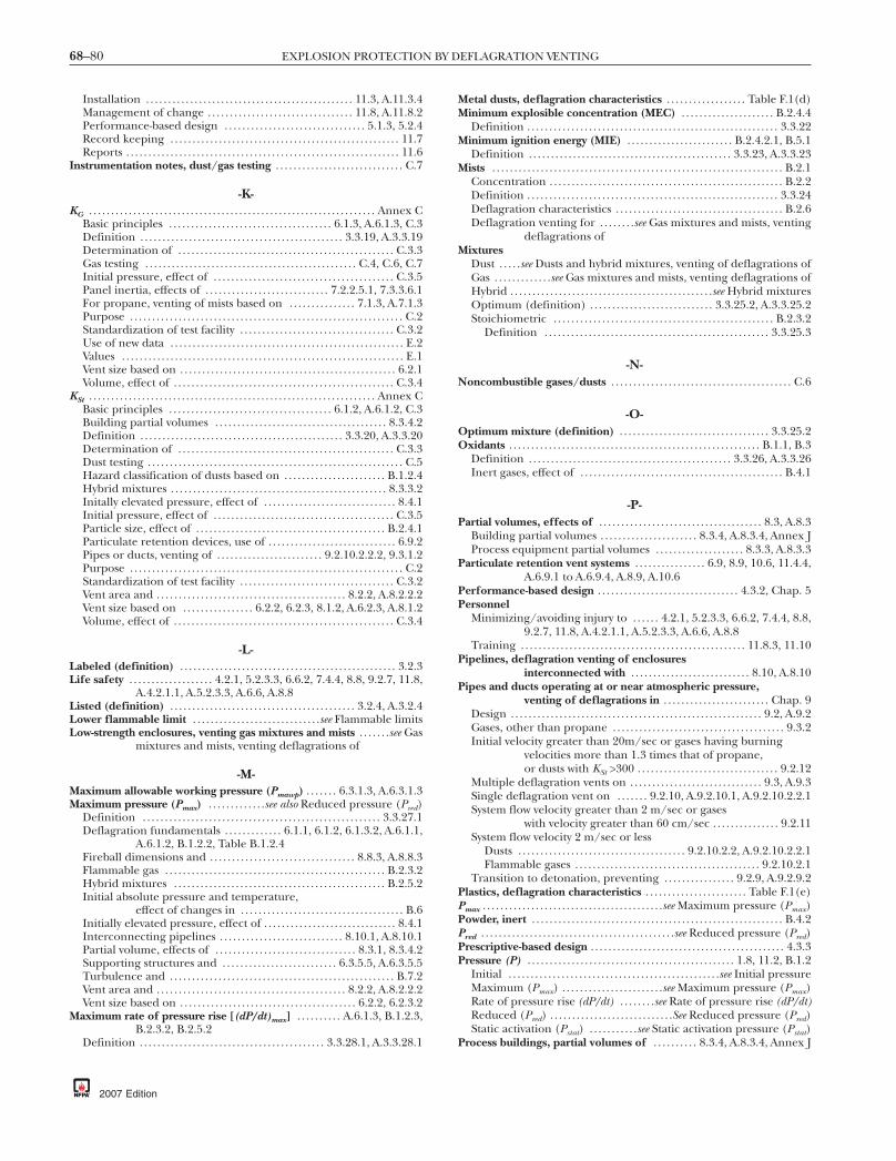
68–80 EXPLOSION PROTECTION BY DEFLAGRATION VENTING
Installation . . . . . . . . . . . . . . . . . . . . . . . . . . . . . . . . . . . . . . . . . . . . . . . 11.3, A.11.3.4Management of change . . . . . . . . . . . . . . . . . . . . . . . . . . . . . . . . . 11.8, A.11.8.2Performance-based design . . . . . . . . . . . . . . . . . . . . . . . . . . . . . . . . 5.1.3, 5.2.4Record keeping . . . . . . . . . . . . . . . . . . . . . . . . . . . . . . . . . . . . . . . . . . . . . . . . . . . . 11.7Reports . . . . . . . . . . . . . . . . . . . . . . . . . . . . . . . . . . . . . . . . . . . . . . . . . . . . . . . . . . . . . . 11.6
Instrumentation notes, dust/gas testing . . . . . . . . . . . . . . . . . . . . . . . . . . . . . C.7
-K-KG . . . . . . . . . . . . . . . . . . . . . . . . . . . . . . . . . . . . . . . . . . . . . . . . . . . . . . . . . . . . . . . . . Annex C
Basic principles . . . . . . . . . . . . . . . . . . . . . . . . . . . . . . . . . . . . . 6.1.3, A.6.1.3, C.3Definition . . . . . . . . . . . . . . . . . . . . . . . . . . . . . . . . . . . . . . . . . . . . . . 3.3.19, A.3.3.19Determination of . . . . . . . . . . . . . . . . . . . . . . . . . . . . . . . . . . . . . . . . . . . . . . . . . C.3.3Gas testing . . . . . . . . . . . . . . . . . . . . . . . . . . . . . . . . . . . . . . . . . . . . . . . . C.4, C.6, C.7Initial pressure, effect of . . . . . . . . . . . . . . . . . . . . . . . . . . . . . . . . . . . . . . . . . C.3.5Panel inertia, effects of . . . . . . . . . . . . . . . . . . . . . . . . . . . . 7.2.2.5.1, 7.3.3.6.1For propane, venting of mists based on . . . . . . . . . . . . . . . 7.1.3, A.7.1.3Purpose . . . . . . . . . . . . . . . . . . . . . . . . . . . . . . . . . . . . . . . . . . . . . . . . . . . . . . . . . . . . . . C.2Standardization of test facility . . . . . . . . . . . . . . . . . . . . . . . . . . . . . . . . . . . C.3.2Use of new data . . . . . . . . . . . . . . . . . . . . . . . . . . . . . . . . . . . . . . . . . . . . . . . . . . . . . E.2Values . . . . . . . . . . . . . . . . . . . . . . . . . . . . . . . . . . . . . . . . . . . . . . . . . . . . . . . . . . . . . . . . E.1Vent size based on . . . . . . . . . . . . . . . . . . . . . . . . . . . . . . . . . . . . . . . . . . . . . . . . . 6.2.1Volume, effect of . . . . . . . . . . . . . . . . . . . . . . . . . . . . . . . . . . . . . . . . . . . . . . . . . . C.3.4
KSt . . . . . . . . . . . . . . . . . . . . . . . . . . . . . . . . . . . . . . . . . . . . . . . . . . . . . . . . . . . . . . . . . Annex CBasic principles . . . . . . . . . . . . . . . . . . . . . . . . . . . . . . . . . . . . . 6.1.2, A.6.1.2, C.3Building partial volumes . . . . . . . . . . . . . . . . . . . . . . . . . . . . . . . . . . . . . . . 8.3.4.2Definition . . . . . . . . . . . . . . . . . . . . . . . . . . . . . . . . . . . . . . . . . . . . . . 3.3.20, A.3.3.20Determination of . . . . . . . . . . . . . . . . . . . . . . . . . . . . . . . . . . . . . . . . . . . . . . . . . C.3.3Dust testing . . . . . . . . . . . . . . . . . . . . . . . . . . . . . . . . . . . . . . . . . . . . . . . . . . . . . . . . . . C.5Hazard classification of dusts based on . . . . . . . . . . . . . . . . . . . . . . . B.1.2.4Hybrid mixtures . . . . . . . . . . . . . . . . . . . . . . . . . . . . . . . . . . . . . . . . . . . . . . . . . 8.3.3.2Initally elevated pressure, effect of . . . . . . . . . . . . . . . . . . . . . . . . . . . . . . 8.4.1Initial pressure, effect of . . . . . . . . . . . . . . . . . . . . . . . . . . . . . . . . . . . . . . . . . C.3.5Particle size, effect of . . . . . . . . . . . . . . . . . . . . . . . . . . . . . . . . . . . . . . . . . . . B.2.4.1Particulate retention devices, use of . . . . . . . . . . . . . . . . . . . . . . . . . . . . . 6.9.2Pipes or ducts, venting of . . . . . . . . . . . . . . . . . . . . . . . . 9.2.10.2.2.2, 9.3.1.2Purpose . . . . . . . . . . . . . . . . . . . . . . . . . . . . . . . . . . . . . . . . . . . . . . . . . . . . . . . . . . . . . . C.2Standardization of test facility . . . . . . . . . . . . . . . . . . . . . . . . . . . . . . . . . . . C.3.2Vent area and . . . . . . . . . . . . . . . . . . . . . . . . . . . . . . . . . . . . . . . . . . . 8.2.2, A.8.2.2.2Vent size based on . . . . . . . . . . . . . . . . 6.2.2, 6.2.3, 8.1.2, A.6.2.3, A.8.1.2Volume, effect of . . . . . . . . . . . . . . . . . . . . . . . . . . . . . . . . . . . . . . . . . . . . . . . . . . C.3.4
-L-Labeled (definition) . . . . . . . . . . . . . . . . . . . . . . . . . . . . . . . . . . . . . . . . . . . . . . . . . 3.2.3Life safety . . . . . . . . . . . . . . . . . . . 4.2.1, 5.2.3.3, 6.6.2, 7.4.4, 8.8, 9.2.7, 11.8,
A.4.2.1.1, A.5.2.3.3, A.6.6, A.8.8Listed (definition) . . . . . . . . . . . . . . . . . . . . . . . . . . . . . . . . . . . . . . . . . . 3.2.4, A.3.2.4Lower flammable limit . . . . . . . . . . . . . . . . . . . . . . . . . . . . .see Flammable limitsLow-strength enclosures, venting gas mixtures and mists . . . . . . .see Gas
mixtures and mists, venting deflagrations of
-M-Maximum allowable working pressure (Pmawp) . . . . . . . 6.3.1.3, A.6.3.1.3Maximum pressure (Pmax) . . . . . . . . . . . . .see also Reduced pressure (Pred)
Definition . . . . . . . . . . . . . . . . . . . . . . . . . . . . . . . . . . . . . . . . . . . . . . . . . . . . . . 3.3.27.1Deflagration fundamentals . . . . . . . . . . . . . 6.1.1, 6.1.2, 6.1.3.2, A.6.1.1,
A.6.1.2, B.1.2.2, Table B.1.2.4Fireball dimensions and . . . . . . . . . . . . . . . . . . . . . . . . . . . . . . . . . 8.8.3, A.8.8.3Flammable gas . . . . . . . . . . . . . . . . . . . . . . . . . . . . . . . . . . . . . . . . . . . . . . . . . . B.2.3.2Hybrid mixtures . . . . . . . . . . . . . . . . . . . . . . . . . . . . . . . . . . . . . . . . . . . . . . . . B.2.5.2Initial absolute pressure and temperature,
effect of changes in . . . . . . . . . . . . . . . . . . . . . . . . . . . . . . . . . . . . . B.6Initially elevated pressure, effect of . . . . . . . . . . . . . . . . . . . . . . . . . . . . . . 8.4.1Interconnecting pipelines . . . . . . . . . . . . . . . . . . . . . . . . . . . . 8.10.1, A.8.10.1Partial volume, effects of . . . . . . . . . . . . . . . . . . . . . . . . . . . . . . . . 8.3.1, 8.3.4.2Supporting structures and . . . . . . . . . . . . . . . . . . . . . . . . . . 6.3.5.5, A.6.3.5.5Turbulence and . . . . . . . . . . . . . . . . . . . . . . . . . . . . . . . . . . . . . . . . . . . . . . . . . . . B.7.2Vent area and . . . . . . . . . . . . . . . . . . . . . . . . . . . . . . . . . . . . . . . . . . . 8.2.2, A.8.2.2.2Vent size based on . . . . . . . . . . . . . . . . . . . . . . . . . . . . . . . . . . . . . . . . 6.2.2, 6.2.3.2
Maximum rate of pressure rise [(dP/dt)max] . . . . . . . . . . A.6.1.3, B.1.2.3,B.2.3.2, B.2.5.2
Definition . . . . . . . . . . . . . . . . . . . . . . . . . . . . . . . . . . . . . . . . . . 3.3.28.1, A.3.3.28.1
2007 Edition
Metal dusts, deflagration characteristics . . . . . . . . . . . . . . . . . . Table F.1(d)Minimum explosible concentration (MEC) . . . . . . . . . . . . . . . . . . . . . B.2.4.4
Definition . . . . . . . . . . . . . . . . . . . . . . . . . . . . . . . . . . . . . . . . . . . . . . . . . . . . . . . . . 3.3.22Minimum ignition energy (MIE) . . . . . . . . . . . . . . . . . . . . . . . . B.2.4.2.1, B.5.1
Definition . . . . . . . . . . . . . . . . . . . . . . . . . . . . . . . . . . . . . . . . . . . . . . 3.3.23, A.3.3.23Mists . . . . . . . . . . . . . . . . . . . . . . . . . . . . . . . . . . . . . . . . . . . . . . . . . . . . . . . . . . . . . . . . . . B.2.1
Concentration . . . . . . . . . . . . . . . . . . . . . . . . . . . . . . . . . . . . . . . . . . . . . . . . . . . . . B.2.2Definition . . . . . . . . . . . . . . . . . . . . . . . . . . . . . . . . . . . . . . . . . . . . . . . . . . . . . . . . . 3.3.24Deflagration characteristics . . . . . . . . . . . . . . . . . . . . . . . . . . . . . . . . . . . . . . B.2.6Deflagration venting for . . . . . . . .see Gas mixtures and mists, venting
deflagrations ofMixtures
Dust . . . . .see Dusts and hybrid mixtures, venting of deflagrations ofGas . . . . . . . . . . . . .see Gas mixtures and mists, venting deflagrations ofHybrid . . . . . . . . . . . . . . . . . . . . . . . . . . . . . . . . . . . . . . . . . . . . . .see Hybrid mixturesOptimum (definition) . . . . . . . . . . . . . . . . . . . . . . . . . . . . 3.3.25.2, A.3.3.25.2Stoichiometric . . . . . . . . . . . . . . . . . . . . . . . . . . . . . . . . . . . . . . . . . . . . . . . . . . B.2.3.2
Definition . . . . . . . . . . . . . . . . . . . . . . . . . . . . . . . . . . . . . . . . . . . . . . . . . . . 3.3.25.3
-N-Noncombustible gases/dusts . . . . . . . . . . . . . . . . . . . . . . . . . . . . . . . . . . . . . . . . . C.6
-O-Optimum mixture (definition) . . . . . . . . . . . . . . . . . . . . . . . . . . . . . . . . . . 3.3.25.2Oxidants . . . . . . . . . . . . . . . . . . . . . . . . . . . . . . . . . . . . . . . . . . . . . . . . . . . . . . . . . B.1.1, B.3
Definition . . . . . . . . . . . . . . . . . . . . . . . . . . . . . . . . . . . . . . . . . . . . . . 3.3.26, A.3.3.26Inert gases, effect of . . . . . . . . . . . . . . . . . . . . . . . . . . . . . . . . . . . . . . . . . . . . . . B.4.1
-P-Partial volumes, effects of . . . . . . . . . . . . . . . . . . . . . . . . . . . . . . . . . . . . . 8.3, A.8.3
Building partial volumes . . . . . . . . . . . . . . . . . . . . . . 8.3.4, A.8.3.4, Annex JProcess equipment partial volumes . . . . . . . . . . . . . . . . . . . . 8.3.3, A.8.3.3
Particulate retention vent systems . . . . . . . . . . . . . . . . 6.9, 8.9, 10.6, 11.4.4,A.6.9.1 to A.6.9.4, A.8.9, A.10.6
Performance-based design . . . . . . . . . . . . . . . . . . . . . . . . . . . . . . . . 4.3.2, Chap. 5Personnel
Minimizing/avoiding injury to . . . . . . 4.2.1, 5.2.3.3, 6.6.2, 7.4.4, 8.8,9.2.7, 11.8, A.4.2.1.1, A.5.2.3.3, A.6.6, A.8.8
Training . . . . . . . . . . . . . . . . . . . . . . . . . . . . . . . . . . . . . . . . . . . . . . . . . . . 11.8.3, 11.10Pipelines, deflagration venting of enclosures
interconnected with . . . . . . . . . . . . . . . . . . . . . . . . . . . 8.10, A.8.10Pipes and ducts operating at or near atmospheric pressure,
venting of deflagrations in . . . . . . . . . . . . . . . . . . . . . . . . Chap. 9Design . . . . . . . . . . . . . . . . . . . . . . . . . . . . . . . . . . . . . . . . . . . . . . . . . . . . . . . . . 9.2, A.9.2Gases, other than propane . . . . . . . . . . . . . . . . . . . . . . . . . . . . . . . . . . . . . . . 9.3.2Initial velocity greater than 20m/sec or gases having burning
velocities more than 1.3 times that of propane,or dusts with KSt >300 . . . . . . . . . . . . . . . . . . . . . . . . . . . . . . . . 9.2.12
Multiple deflagration vents on . . . . . . . . . . . . . . . . . . . . . . . . . . . . . . 9.3, A.9.3Single deflagration vent on . . . . . . . 9.2.10, A.9.2.10.1, A.9.2.10.2.2.1System flow velocity greater than 2 m/sec or gases
with velocity greater than 60 cm/sec . . . . . . . . . . . . . . . 9.2.11System flow velocity 2 m/sec or less
Dusts . . . . . . . . . . . . . . . . . . . . . . . . . . . . . . . . . . . . . . 9.2.10.2.2, A.9.2.10.2.2.1Flammable gases . . . . . . . . . . . . . . . . . . . . . . . . . . . . . . . . . . . . . . . . . . 9.2.10.2.1
Transition to detonation, preventing . . . . . . . . . . . . . . . . 9.2.9, A.9.2.9.2Plastics, deflagration characteristics . . . . . . . . . . . . . . . . . . . . . . . Table F.1(e)Pmax . . . . . . . . . . . . . . . . . . . . . . . . . . . . . . . . . . . . . . . . .see Maximum pressure (Pmax)Powder, inert . . . . . . . . . . . . . . . . . . . . . . . . . . . . . . . . . . . . . . . . . . . . . . . . . . . . . . . . . B.4.2Pred . . . . . . . . . . . . . . . . . . . . . . . . . . . . . . . . . . . . . . . . . . . .see Reduced pressure (Pred)Prescriptive-based design . . . . . . . . . . . . . . . . . . . . . . . . . . . . . . . . . . . . . . . . . . . . 4.3.3Pressure (P) . . . . . . . . . . . . . . . . . . . . . . . . . . . . . . . . . . . . . . . . . . . . . . . 1.8, 11.2, B.1.2
Initial . . . . . . . . . . . . . . . . . . . . . . . . . . . . . . . . . . . . . . . . . . . . . . . .see Initial pressureMaximum (Pmax) . . . . . . . . . . . . . . . . . . . . . . .see Maximum pressure (Pmax)Rate of pressure rise (dP/dt) . . . . . . . .see Rate of pressure rise (dP/dt)Reduced (Pred) . . . . . . . . . . . . . . . . . . . . . . . . . . . .See Reduced pressure (Pred)Static activation (Pstat) . . . . . . . . . . .see Static activation pressure (Pstat)
Process buildings, partial volumes of . . . . . . . . . . 8.3.4, A.8.3.4, Annex J

68–81INDEX
Property damage, minimizing/avoiding . . . . 4.2.2, 5.2.3.2, 6.6.2, 7.4.4,8.8, 11.8, A.4.2.2.2, A.5.2.3.2, A.6.6, A.8.8
Pstat . . . . . . . . . . . . . . . . . . . . . . . . . . . . . . . . . . .see Static activation pressure (Pstat)Purpose of standard . . . . . . . . . . . . . . . . . . . . . . . . . . . . . . . . . . . . . . . . . . . . 1.2, A.1.2
-R-Rate of pressure rise (dP/dt)
Definition . . . . . . . . . . . . . . . . . . . . . . . . . . . . . . . . . . . . . . . . . . . . . . . . . . . . . . . . . 3.3.28Deflagration fundamentals . . . . . . . . . . . . . . . . . . . . . . . . . . . B.1.2.2, B.1.2.3Ignition source location, effect of . . . . . . . . . . . . . . . . . . . . . . . . . . . . . . . B.5.3Maximum . . . . . . . . . . .see Maximum rate of pressure rise [(dP/dt)max]Multiple simultaneous ignition sources, effect of . . . . . . . . . . . . . . B.5.4Turbulence, effect of . . . . . . . . . . . . . . . . . . . . . . . . . . . . . . . . . . . . . . . . . . . . . B.7.2
Reduced pressure (Pred)Bins, hoppers, and silos . . . . . . . . . . . . . . . . . . . . . . . . . . . . . . . . . . . . . . . . 8.6.3.4Consequences of deflagration and . . . . . . . . . . . . . . . . . . . . . . . . . . . . . . A.6.6Definition . . . . . . . . . . . . . . . . . . . . . . . . . . . . . . . . . . . . . . . . . . . . . . . . . . . . . . 3.3.27.2Design pressure selection criteria . . . . . . . . . . . . . . . . . . . . 6.3.1.1, 6.3.1.2,
6.3.1.3.2, A.6.3.1.1Enclosure design and support . . . . . . . . . . . . . . . . . . . . . . . . . . 6.3.2, A.6.3.2Enclosure length-to-diameter ratio and
vent variables . . . . . . . . . . . . . . . . . . . . . . . . . . 6.4.1, A.6.4, A.6.4.4Fireball dimensions and . . . . . . . . . . . . . . . . . . . . . . . . . . . . . . . . . 8.8.3, A.8.8.3High-strength enclosures . . . . . . . . . . . . . . . . . . . . . . . . . . . . . . . 7.3.1, 7.3.3.2,
7.3.3.3.1, 7.3.3.6.2, A.7.3.1Hinged vent closures, effect of . . . . . . . . . . . . . . . . . . . . . . . . . . . . . . . . A.6.7.4Initial elevated pressure, effect of . . . . . . . . . . . . . . . . . . . . . . . . 7.6.1, 8.4.1Interconnecting pipelines . . . . . . . . . . . . . . . . . . . . . . . . . . . . 8.10.1, A.8.10.1Low inertia vent closures, venting by means of . . . . . 8.2.2, A.8.2.2.2Low-strength enclosures . . . . . . . . . . . . . . . . . . . . . . . . . 7.2.1, 7.2.2, 7.2.6.1,
A.7.2.2, A.7.2.5, A.7.2.6.1Normally closed vents . . . . . . . . . . . . . . . . . . . . . . . . . . . . . . . . . . . . . . . 10.2.2.2.1Openings and . . . . . . . . . . . . . . . . . . . . . . . . . . . . . . . . . . . . . . . . . . . . . . . . . . . 6.3.3.4Panel density, increase with . . . . . . . . . . . . . . . . . . . . . . . . . . . . . . . . . . . . A.6.7.2Partial volume, effects of . . . . . . . . . . . . . . . . . . . . . . . . . . . . . . . . 8.3.1, 8.3.4.2Particulate retention devices, use of . . . . . . . . . . . . . . . . . . . . . . . . . . . . . 6.9.2In pipe or duct . . . . . . . . . . . . . 9.2.10.2, Fig. 9.3.1, 9.3.2, A.9.2.10.2.2.1Supporting structures and . . . . . . 6.3.5.2, 6.3.5.5, A.6.3.5.2, A.6.3.5.5Vent ducts, effect of . . . . . . . . . . . . . . . . . . . . . . . 6.8.5, 7.4.1, 7.4.2, 7.4.3.1,
7.4.3.3, 7.4.3.4, A.7.4.1, A.7.4.6Vent mass, effect of . . . . . . . . . . . . . . . . . . . . . . . . . . . . . . . . . . . . . . . . . . . . . A.6.7.1
References . . . . . . . . . . . . . . . . . . . . . . . . . . . . . . . . . . . . . . . . . . . . . Chap. 2, Annex LReplacement-in-kind . . . . . . . . . . . . . . . . . . . . . . . . . . . . . . . . . . . . . . . . . . . . . . . . 11.8.4
Definition . . . . . . . . . . . . . . . . . . . . . . . . . . . . . . . . . . . . . . . . . . . . . . . . . . . . . . . . . 3.3.30Research reports and supporting documents . . . . . . . . . . . . . . . . . . Annex IRetroactivity of standard . . . . . . . . . . . . . . . . . . . . . . . . . . . . . . . . . . . . . . . . . . . . . . 1.5Rupture diaphragm devices . . . . . . . . . . . . . . . . . . 6.3.5.4.1, 10.5.2, A.10.5.2
-S-Scope of standard . . . . . . . . . . . . . . . . . . . . . . . . . . . . . . . . . . . . . . . . . . . . . . . 1.1, A.1.1Shall (definition) . . . . . . . . . . . . . . . . . . . . . . . . . . . . . . . . . . . . . . . . . . . . . . . . . . . . . 3.2.5Should (definition) . . . . . . . . . . . . . . . . . . . . . . . . . . . . . . . . . . . . . . . . . . . . . . . . . . 3.2.6Silos, deflagration venting for . . . . . . . . . . . . . . . . . . . . . . . . 6.4.1, 8.2.3.1, 8.6,
A.8.2.3.1, A.8.6.1, A.8.6.3Spray dryers . . . . . . . . . . . . . . . . . . . . . . . . . . . . . . . . . . . . . . . . . . . . . . . 8.3.3.3, 8.3.3.4Standard (definition) . . . . . . . . . . . . . . . . . . . . . . . . . . . . . . . . . . . . . . . . . . . . . . . . 3.2.7Static activation pressure (Pstat) . . . . . . . . . . . . . . . . . . . . . . 8.2.2, 8.4.1, 8.5.1,
A.6.3.1.1, A.6.4.4, A.8.2.2.2Definition . . . . . . . . . . . . . . . . . . . . . . . . . . . . . . . . . . . . . . . . . . . . . . . . . . . . . . 3.3.27.3Hinged vent closures, effect of . . . . . . . . . . . . . . . . . . . . . . . . . . . . . . . . A.6.7.4Interconnecting pipelines . . . . . . . . . . . . . . . . . . . . . . . . . . . . 8.10.1, A.8.10.1Normally closed vents . . . . . . . . . . . . . . . . . . . . . . . . . . . . . . . . . . . 10.2.1, 10.2.2Vent closures, released by . . . . . . . . . . . . . . . . . . . . . . . . . . . . . . . . . . . . A.7.2.6.1Of vent panels . . . . . . . . . . . . . . . . . . . . . . . . . . . . . . . . . . . . . . . . . . . . . . . . . 6.3.5.4.1
Stoichiometric mixture . . . . . . . . . . . . . . . . . . . . . . . . . . . . . . . . . . . . . . . . . . . . B.2.3.2Definition . . . . . . . . . . . . . . . . . . . . . . . . . . . . . . . . . . . . . . . . . . . . . . . . . . . . . . 3.3.25.3
StrengthEnclosures (Pes) . . . . . . . . . . . . . . . . . . . . . . 6.3.1 to 6.3.3, A.6.3.2, A.6.3.3.1
Definition . . . . . . . . . . . . . . . . . . . . . . . . . . . . . . . . . . . . . . . . . . . . . . . . . . . 3.3.32.1High-strength enclosure . . . . .see Gas mixtures and mists, venting
deflagrations of
Low-strength enclosure . . . . . .see Gas mixtures and mists, ventingdeflagrations of
Ultimate . . . . . . . . . . . . . 6.3.1.1, 6.3.1.3.1, 6.3.1.3.2, 6.3.1.4.2, A.6.3.1.1Definition . . . . . . . . . . . . . . . . . . . . . . . . . . . . . . . . . . . . . . . . . . . . . . . . . . . 3.3.32.2
Symbols . . . . . . . . . . . . . . . . . . . . . . . . . . . . . . . . . . . . . . . . . . . . . . . . . . . . . . . . . . . . . . . . . 1.7System flow velocity greater than 2 m/sec or gases with velocity
greater than 60 cm/sec . . . . . . . . . . . . . . . . . . . . . . . . . . . . . . 9.2.11System flow velocity 2 m/sec or less
Dusts . . . . . . . . . . . . . . . . . . . . . . . . . . . . . . . . . . . . . . . . . 9.2.10.2.2, A.9.2.10.2.2.1Flammable gases . . . . . . . . . . . . . . . . . . . . . . . . . . . . . . . . . . . . . . . . . . . . . 9.2.10.2.1
-T-Temperature . . . . . . . . . . . . . . . . . . . . . . . . . . . . . . . . . . . . . . .see Initial temperatureTesting
Dusts . . . . . . . . . . . . . . . . . . . . . . . . . . . . . . . . . . . . . . . . . . . . . . . . . . . . . . . . . . . . . . . . . C.5Gases . . . . . . . . . . . . . . . . . . . . . . . . . . . . . . . . . . . . . . . . . . . . . . . . . . . . . . . . . . . . . . . . . C.4
Turbulence . . . . . . . . . . . . . . . . . . . . . . . . . . . . . . . . . . . . . . . . . . . . . . . . . . . . . . . . . . . . . B.7Initial turbulence and internal appurtenances for enclosures with
initial pressure near atmospheric, effects of . . . 7.5, A.7.5
-U-Ultimate strength . . . . . . . . . . . . . . . . . . . . . . . . . . . . . . . . . . . . . . . . . . . . .see StrengthUpper flammable limit . . . . . . . . . . . . . . . . . . . . . . . . . . . . .see Flammable limits
-V-Vapor . . . . . . . . . . . . . . . . . . . . . . . . . . . . . . . . . . . . . . . . . . . . . . . . . . . . . . . . . . . . . . . . .see GasVent area . . . . . . . . . . . . . . . . . . . . 6.4.4, 6.4.5, A.6.1.3, A.6.4.4, A.6.4.5, B.7.2
High-strength enclosures . . . . . . . . . . . . . . . . 7.3.3, A.7.3.3.2 to A.7.3.3.6Low inertia vent closures, venting by means of . . . . . . . 8.2.2 to 8.2.9,
A.8.2.2.2 to A.8.2.8Low-strength enclosures, methods to reduce vent
areas of . . . . . . . . . . . . . . . . . . . . . . . . . . . . . . . . . . . . . . . . 7.2.5, A.7.2.5Partial volume, effects of . . . . . . . . . . . . . . . . . . . . . . . . . . . . . . . . 8.3.1, 8.3.4.2Pipe, duct, or elongated vessel, vent location along . . . . 9.2.1, 9.2.2Vent ducts, effect of . . . . . . . . . . . . . . . . . . . . . . . . . . . . . . . . . . . . . . . . . . . . . . . A.7.4
Vent closures . . . . . . . . . . . . . . . . . . . . . . . . . . . . . . . . . . . . . . . . . . . . . . 9.2.6, Chap. 10Bins, hoppers, and silos . . . . . . . . . . . . . . . 8.6.1.1, 8.6.1.4, 8.6.2, 8.6.3.3Definition . . . . . . . . . . . . . . . . . . . . . . . . . . . . . . . . . . . . . . . . . . . . . . . . . . . . . . . . . 3.3.35Equipment vent closures . . . . . . . . . . . . . . . . . . . . . . . . . . . . . . . 10.5, A.10.5.1
Hinged devices . . . . . . . . . . . . . . . . . . . . . . . . . . . . . . . . . . . . . 10.5.1, A.10.5.1Rupture diaphragm devices . . . . . . . . . . . . . . . . . . . . . . . 10.5.2, A.10.5.2
Hangar-type doors . . . . . . . . . . . . . . . . . . . . . . . . . . . . . . . . . . . . . . . . . . . . . . . 10.1.2High-strength enclosures . . . . . . . . . . . . . . . . . . . . . . . . . . . 7.3.2.3 to 7.3.2.6Hinged closures . . . . . . . . . . . . . . . . . . . . . . . . . . . . . . . . . . 6.7.4, 11.4.4, A.6.7.4
Doors, windows, and panels . . . . . . . . . . . . . . . . . . . . . . . . . . . . . . . . . 10.3.1Equipment vent closures . . . . . . . . . . . . . . . . . . . . . . . . . . 10.5.1, A.10.5.1Vent panels . . . . . . . . . . . . . . . . . . . . . . . . . . . . . . . . . . . . . . . . . . . . . . . . . . . . 10.3.1
Inertia . . . . . . . . . . . . . . . . . . . . . . . . . . . . . . . . . . 6.7.2 to 6.7.4, A.6.7.2, A.6.7.4Low inertia closures . . . . . . . . . . . . . . . . . . . . . . . 8.2, A.8.2.2.2 to A.8.2.8
Inspection and maintenance . . . . . . . . . . . . . . . . . . . . . . . . . . . . . . . . Chap. 11Installation . . . . . . . . . . . . . . . . . . . . . . . . . . . . . . . . . . . . . . . . . . . . . . . 11.3, A.11.3.4Louvered openings . . . . . . . . . . . . . . . . . . . . . . . . . . . . . . . . . . . . . . . . . . . . . . 10.1.1Low-strength enclosures . . . . . . . . . . . . . . . . . . . 7.2.6.3, 7.2.6.4, A.7.2.6.4Marking . . . . . . . . . . . . . . . . . . . . . . . . . . . . . . . . . . . . . . . . . . . . . . . . 11.3.4, A.11.3.4Normally closed vents . . . . . . . . . . . . . . . . . . . . . . . . . . . . . . . . . . . . . . . . . . . . . 10.2Operation . . . . . . . . . . . . . . . . . . . . . . . . 6.5, 7.3.2.3, 11.2, A.6.5.1 to A.6.5.7Panels . . . . . . . . . . . . . . . . . . . . . . . . . . . . . . . . . . . . . . . . . . . . . . . . . . . .see Vent panelsSnow, ice, and other deposits . . . . . . . . . . . . . . . . . . . . . . . . 6.5.2, 7.3.2.3.1,
7.3.2.3.2, 11.4.4, 11.9.1, A.6.5.2.1Types of building or room vent closures . . . . . . . . . . . . . . 10.3, A.10.3.2
Hinged doors, windows, and panels . . . . . . . . . . . . . . . . . . . . . . . . 10.3.1Shear and pull-through fasteners . . . . . . . . . . . . . . . . . 10.3.2, A.10.3.2
Venting/vents . . . . . . . . . . . . . . . . . . . . . . . . . . . . . . . . . . . . . . . . . . . . . . . . . . . . Chap. 10Air intakes, location relative to . . . . . . . . . . . . . . . . . . . . . . . . . . . . . . . . 6.6.2.1Area . . . . . . . . . . . . . . . . . . . . . . . . . . . . . . . . . . . . . . . . . . . . . . . . . . . . . . . .see Vent areaBasic concepts . . . . . . . . . . . . . . . . . . . . . . . . . . . . . . . . . . . . . . . . . . . . . . . . 6.1, A.6.1Closures . . . . . . . . . . . . . . . . . . . . . . . . . . . . . . . . . . . . . . . . . . . . . . . .see Vent closuresDefinition . . . . . . . . . . . . . . . . . . . . . . . . . . . . . . . . . . . . . . . . . . . . . . . . . . . . . . . . . 3.3.34Deflectors . . . . . . . . . . . . . . . . . . . . 6.6.2.3 to 6.6.2.5, A.6.6.2.3 to A.6.6.2.5Design . . . . . . . . . . . . . . . . . . . . . . . . . . . . . . . . . . . . . . . . . . . . . . . . . . . . . . . . . . . B.2.4.7
2007 Edition

68–82 EXPLOSION PROTECTION BY DEFLAGRATION VENTING
Enclosures with L/D less than or equal to 6 handlingcombustible dust or hybrid mixtures . . . . . . . . . . . . Chap. 8
Enclosures with L/D less than or equal to 5 thatcontain gas or mist . . . . . . . . . . . . . . . . . . . . . . . . . . . . . . . . Chap. 7
DischargeLocation of . . . . . . . . . . . . . . . . . . . . . . . 4.2.1.3, 6.5.1, 6.9.4, 7.4.4, 7.4.5,
9.2.7, A.5.2.3.3, A.6.5.1, A.6.9.4, A.7.4.5Performance-based design . . . . . . . . . . . . . . 5.2.3, A.5.2.3.2, A.5.2.3.3
Ducts . . . . . . . . . . . . . . . . . . . . . . . . . . . . . . . . . . . . . . . . . . . . . . . . . . . . . . . . . . . .see DuctsDusts, venting of . . . . . . . . . .see Dusts and hybrid mixtures, venting of
deflagrations ofEnclosure length-to-diameter ratio and vent variables . . . 6.4, A.6.4Enclosures . . . . . . . . . . . . . . . . . . . . . . . . . . . . . . . . . . . . . . . . . . . . . . . .see EnclosuresFlame arresting and particulate retention systems . . . . . . . . . . . . . . 6.9,
A.6.9.1 to A.6.9.4Flame-arresting and particulate retention systems . . . . . 10.6, A.10.6Fundamentals . . . . . . . . . . . . . . . . . . . . . . . . . . . . . . . . . . . . . . . . . . . . . . . . . . Chap. 6Gas mixtures, venting of . . . . . . . .see Gas mixtures and mists, venting
deflagrations ofHangar-type doors . . . . . . . . . . . . . . . . . . . . . . . . . . . . . . . . . . . . . . . . . . . . . . . 10.1.2Hybrid mixtures . . . . . . . . . .see Dusts and hybrid mixtures, venting of
deflagrations ofIndoors . . . . . . . . . . . . . . . . . . . . . . . . . . . . . . . . . . . . . . . . . . . . . . . . . . . . . . . . . . A.6.9.4Inertia, effects of . . . . . . . . . . . . . 6.7, 7.2.2.5, 7.3.3.6, A.6.7.1 to A.6.7.4,
A.7.2.2.5, A.7.3.3.6Life safety . . . . . . . . . . . . . . . . . 4.2.1, 5.2.3.3, 6.6.2, 7.4.4, 8.8, 9.2.7, 11.8,
A.4.2.1.1, A.5.2.3.3, A.6.6, A.8.8Location . . . . . . . . . . . . . . . . . . . . . . . . . . . . . . . . . . . . . . . . . . 6.6.2.1, 6.6.2.2, 6.6.3
For life safety . . . . . . . . . . . . . . . . . 4.2.1.3, 6.6.2, A.6.6.2.3 to A.6.6.2.5
2007 Edition
Pipe, duct, or elongated vessel, vent location along . . . 9.2.1, 9.2.2,9.2.4, 9.2.5, 9.2.7, A.9.2.4
To prevent transition to detonation . . . . . . . . . . . . . . . . . . . . . . . . 9.2.9.1For property protection . . . . . . . . . . 4.2.2, 6.6.2, A.4.2.2.2, A.6.6.2.3
to A.6.6.2.5Louvered openings . . . . . . . . . . . . . . . . . . . . . . . . . . . . . . . . . . . . . . . . . . . . . . 10.1.1Mists, venting of . . . . . . . . . . . . . . . . . . . . . . . . . .see Gas mixtures and mists,
venting deflagrations ofPanels . . . . . . . . . . . . . . . . . . . . . . . . . . . . . . . . . . . . . . . . . . . . . . . . . . . .see Vent panelsPerformance-based design . . . . . . . . . . . . . . . . . . . . . . . . . . . . . 4.3.2, Chap. 5Pipes . . . . . . . . .see Pipes and ducts operating at or near atmospheric
pressureSize . . . . . 6.1.2.2, 8.1.1.3, 8.1.1.4, 8.1.2, A.8.1.2, B.1.2.4; see also Vent
areaDust mixtures . . . . . . . . . . . . . . . . . . . . . . . . . . . . . . . . . . . . . . . . . . . . . . . . . . . 6.2.2Gas mixtures . . . . . . . . . . . . . . . . . . . . . . . . . . . . . . . . . . . . . . . . . . . . . . . . . . . . 6.2.1Hybrid mixtures . . . . . . . . . . . . . . . . . . . . . . . . . . . . . . . . . . . . . . . 6.2.3, A.6.2.3
Turbulence, effect on . . . . . . . . . . . . . . . . . . . . . . . . . . . . . . . . . .see TurbulenceVent panels
Calculation method for correction factor due to increased ventpanel mass . . . . . . . . . . . . . . . . . . . . . . . . . . . . . . . . . . . . . . . . Annex G
Hinged panel closures . . . . . . . . . . . . . . . . . . . . . . . . . . . . . . . . . . . . . . . . . . 10.3.1Inertia effect . . . . . . . . . . . . . . . . . . . . . 7.2.2.5, 7.3.3.6, A.7.2.2.5, A.7.3.3.6Large panels
Restraints for . . . . . . . . . . . . . . . . . . . . . . . . . . . . . . . . . . . . . . . . . . . . 10.4, A.10.4Of rupture diaphragm type . . . . . . . . . . . . . . . . . . . . . . . . . . . . . . . . . . 6.3.5.4.1
-W-Warning signs . . . . . . . . . . . . . . . . . . . . . . . . . . . 6.6.3, 11.3.4, A.5.2.3.3, A.11.3.4
Cou/W07 0 8 09 10 6 5 4 3 2 1

Tentative Interim Amendment
NFPA 68 Standard on Explosion Protection by Deflagration Venting
2007 Edition Reference: Various Sections TIA 07-1 (SC 08-10-2/TIA Log #928) Pursuant to Section 5 of the NFPA Regulations Governing Committee Projects, the National Fire Protection Association has issued the following Tentative Interim Amendment to NFPA 68, Standard on Explosion Protection by Deflagration Venting, 2007 edition. The TIA was processed by the Technical Committee on Explosion Protection Systems, and was issued by the Standards Council on October 28, 2008, with an effective date of November 17, 2008. A Tentative Interim Amendment is tentative because it has not been processed through the entire standards-making procedures. It is interim because it is effective only between editions of the standard. A TIA automatically becomes a proposal of the proponent for the next edition of the standard; as such, it then is subject to all of the procedures of the standards-making process. 1. In equations 7.2.2.6, 7.3.3.7, and 8.2.8 the terms V and Pred are in the numerator and need to be moved to the denominator as shown in the revised equations below:
⎥⎦
⎤⎢⎣
⎡••
•••=∆ 2.03.0
5.06.0)0075.0(
red
Gvi PVn
KMAA 7.2.2.6
⎥⎦
⎤⎢⎣
⎡••
•••=∆ 2.03.0
5.06.0)0075.0(
red
Gvi PVn
KMAA 7.3.3.7
⎥⎦
⎤⎢⎣
⎡••
••+•= 2.03.0
5.06.0
23)0075.0(1
red
stvv PVn
KMAA 8.2.8
2. In 8.2.8 revise the text to read as shown:
“If M > MT, the vent area shall be increased by adding the calculated area, Av3, from Equation 8.2.8:” “For M > MT, the required vent area, Av3 , shall be calculated as follows:”
3. In 8.2.7.1, revise the text to read as shown:
8.2.7.1 When the mass of the vent panel is less than or equal to 40 kg/m2 and KSt is less than or equal to 250 bar-m/sec, Equation 8.2.7.2 shall be used to determine whether an incremental increase in vent area is needed and the requirements of 8.2.8 shall be used to determine the value of that increase.
(continued)
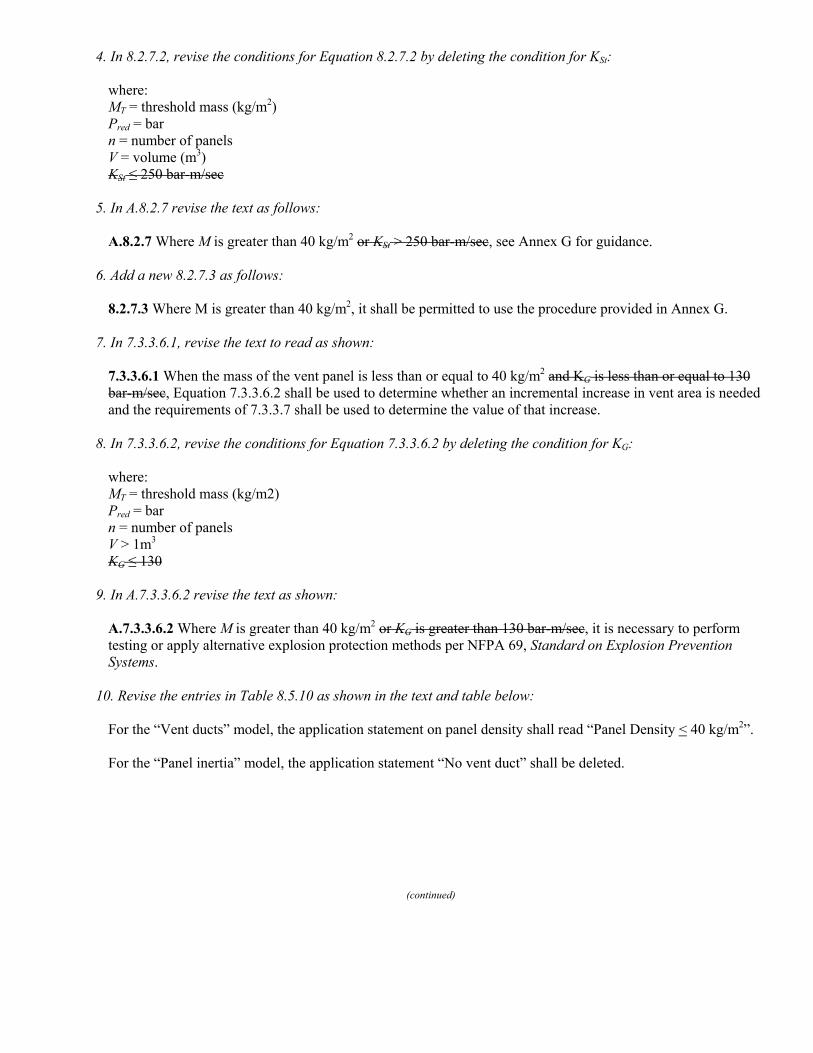
4. In 8.2.7.2, revise the conditions for Equation 8.2.7.2 by deleting the condition for KSt:
where: MT = threshold mass (kg/m2) Pred = bar n = number of panels V = volume (m3) KSt ≤ 250 bar-m/sec
5. In A.8.2.7 revise the text as follows:
A.8.2.7 Where M is greater than 40 kg/m2 or KSt > 250 bar-m/sec, see Annex G for guidance.
6. Add a new 8.2.7.3 as follows:
8.2.7.3 Where M is greater than 40 kg/m2, it shall be permitted to use the procedure provided in Annex G. 7. In 7.3.3.6.1, revise the text to read as shown:
7.3.3.6.1 When the mass of the vent panel is less than or equal to 40 kg/m2 and KG is less than or equal to 130 bar-m/sec, Equation 7.3.3.6.2 shall be used to determine whether an incremental increase in vent area is needed and the requirements of 7.3.3.7 shall be used to determine the value of that increase.
8. In 7.3.3.6.2, revise the conditions for Equation 7.3.3.6.2 by deleting the condition for KG:
where: MT = threshold mass (kg/m2) Pred = bar n = number of panels V > 1m3 KG ≤ 130
9. In A.7.3.3.6.2 revise the text as shown:
A.7.3.3.6.2 Where M is greater than 40 kg/m2 or KG is greater than 130 bar-m/sec, it is necessary to perform testing or apply alternative explosion protection methods per NFPA 69, Standard on Explosion Prevention Systems.
10. Revise the entries in Table 8.5.10 as shown in the text and table below:
For the “Vent ducts” model, the application statement on panel density shall read “Panel Density < 40 kg/m2”. For the “Panel inertia” model, the application statement “No vent duct” shall be deleted.
(continued)

11. Revise 6.8.2 as shown and add the reference to the paper by Hey, “Pressure relief of dust explosions through large diameter ducts and effect of changing the position of the ignition source”, J. Loss Prev. Process Ind., 1991, Vol 4, July, pg 217. :
6.8.2A vent duct shall have a cross sectional area at least as great as that of the vent itself but shall be limited to no more than 150% of the vent itself at any point in the vent duct. [Hey]
12. Revise 8.7.1(3) as follows:
(3) Locate the vents such that the bottom of the vent(s) is at or above below the bottom of the bags, as shown in Figure 8.7.1 (e), and the row of bags closest to the vent are restrained from passing through the vent. For this case, the volume used to calculate the vent area shall be the entire volume (clean and dirty) below the tube sheet.
13. Keep the current Figure 8.7.1 (e) and add this second drawing as part of the same figure with the current drawing on the left side and this drawing adjacent on the right:
(continued)

14. In equation 7.3.3.2, the constant to be subtracted from Pstat should be 0.1 bar.
15. Revise 8.7.1(2) as follows:
(2) Locate the vents as shown in Figure 8.7.1(c) and Figure 8.7.1(d), and bags are either completely removed or shortened so that they do not extend below the top of the vent for a distance of one vent diameter from the vent. In addition, the bags immediately adjacent to the vent shall be removed and the remaining bags the bags which extend below the top of the vent shall be verified by test to be rigid enough to remain in place during venting, or shall be restrained from passing through the vent. For this case, the vent area shall be permitted to be calculated on the basis of the dirty side only; that is, calculate the volume below the tube sheet, and subtract out the volume occupied by the bags.
Issue Date: October 28, 2008 Effective Date: November 17, 2008 (Note: For further information on NFPA Codes and Standards, please see www.nfpa.org/codelist)
Copyright © 2008 All Rights Reserved NATIONAL FIRE PROTECTION ASSOCIATION

Sequence of Events Leading to Issuance of an NFPA Committee Document
Step 1: Call for Proposals
• Proposed new Document or new edition of an existing Document is entered into one of two yearly revision cy-cles, and a Call for Proposals is published.
Step 2: Report on Proposals (ROP)
• Committee meets to act on Proposals, to develop its own Proposals, and to prepare its Report.
• Committee votes by written ballot on Proposals. If two-thirds approve, Report goes forward. Lacking two-thirds approval, Report returns to Committee.
• Report on Proposals (ROP) is published for public re-view and comment.
Step 3: Report on Comments (ROC)
• Committee meets to act on Public Comments to develop its own Comments, and to prepare its report.
• Committee votes by written ballot on Comments. If two-thirds approve, Report goes forward. Lacking two-thirds approval, Report returns to Committee.
• Report on Comments (ROC) is published for public re-view.
Step 4: Technical Report Session
• “Notices of intent to make a motion” are filed, are reviewed, and valid motions are certified for presentation at the Technical Report Session. (“Consent Documents” that have no certified motions bypass the Technical Report Session and proceed to the Standards Council for issu-ance.)
• NFPA membership meets each June at the Annual Meet-ing Technical Report Session and acts on Technical Committee Reports (ROP and ROC) for Documents with “certified amending motions.”
• Committee(s) vote on any amendments to Report ap-proved at NFPA Annual Membership Meeting.
Step 5: Standards Council Issuance
• Notification of intent to file an appeal to the Standards Council on Association action must be filed within 20 days of the NFPA Annual Membership Meeting.
• Standards Council decides, based on all evidence, whether or not to issue Document or to take other ac-tion, including hearing any appeals.
Committee Membership ClassificationsThe following classifications apply to Technical Commit-tee members and represent their principal interest in the activity of the committee.
M Manufacturer: A representative of a maker or mar-keter of a product, assembly, or system, or portion thereof, that is affected by the standard.
U User: A representative of an entity that is subject to the provisions of the standard or that voluntarily uses the standard.
I/M Installer/Maintainer: A representative of an entity that is in the business of installing or maintaining a product, assembly, or system affected by the stan-dard.
L Labor: A labor representative or employee con-cerned with safety in the workplace.
R/T Applied Research/Testing Laboratory: A representative of an independent testing laboratory or indepen-dent applied research organization that promul-gates and/or enforces standards.
E Enforcing Authority: A representative of an agency or an organization that promulgates and/or en-forces standards.
I Insurance: A representative of an insurance com-pany, broker, agent, bureau, or inspection agency.
C Consumer: A person who is, or represents, the ul-timate purchaser of a product, system, or service affected by the standard, but who is not included in the User classification.
SE Special Expert: A person not representing any of the previous classifications, but who has a special expertise in the scope of the standard or portion thereof.
NOTES;1. “Standard” connotes code, standard, recommended practice, or guide.2. A representative includes an employee.3. While these classifications will be used by the Standards Council to achieve a balance for Technical Committees, the Standards Council may determine that new classifi-cations of members or unique interests need representa-tion in order to foster the best possible committee delib-erations on any project. In this connection, the Standards Council may make appointments as it deems appropriate in the public interest, such as the classification of “Utili-ties” in the National Electrical Code Committee.4. Representatives of subsidiaries of any group are gener-ally considered to have the same classification as the par-ent organization.

NFPA Technical Committee Document Proposal Form
NOTE: All Proposals must be received by 5:00 pm EST/EDST on the published Proposal Closing Date.
For further information on the standards-making process, please contact the Codes and Standards Administration at 617-984-7249 or visit www.nfpa.org/codes.
For technical assistance, please call NFPA at 1-888-344-3555.
FOR OFFICE USE ONLY
Log #:
Date Rec’d:
Please indicate in which format you wish to receive your ROP/ROC electronic paper download (Note: If choosing the download option, you must view the ROP/ROC from our website; no copy will be sent to you.)
Date April 1, 200X Name John J. Doe Tel. No. 716-555-1234
Company Air Canada Pilot's Association
Street Address 123 Summer Street Lane City Lewiston State NY Zip 14092
Please indicate organization represented (if any)
1. (a) NFPA Document Title National Fuel Gas Code NFPA No. & Year 54, 200X Edition
(b) Section/Paragraph 3.3
2. Proposal Recommends (check one): new text revised text deleted text
3. Proposal (include proposed new or revised wording, or identification of wording to be deleted): [Note: Proposed text should be in legislative format; i.e., use underscore to denote wording to be inserted (inserted wording) and strike-through to denote wording to be deleted (deleted wording).]
Revise definition of effective ground-fault current path to read:
3.3.78 Effective Ground-Fault Current Path. An intentionally constructed, permanent, low impedance electrically conductive path designed and intended to carry underground electric fault current conditions from the point of a ground fault on a wiring system to the electrical supply source.
4. Statement of Problem and Substantiation for Proposal: (Note: State the problem that would be resolved by your recommendation; give the specific reason for your Proposal, including copies of tests, research papers, fire experience, etc. If more than 200 words, it may be abstracted for publication.)
Change uses proper electrical terms.
5. Copyright Assignment
(a) I am the author of the text or other material (such as illustrations, graphs) proposed in this Proposal.
(b) Some or all of the text or other material proposed in this Proposal was not authored by me. Its source is as follows (please identify which material and provide complete information on its source):
ABC Co. I agree that any material that I author, either individually or with others, in connection with work performed by an NFPA Technical Committee shall be considered to be works made for hire for the NFPA. To the extent that I retain any rights in copyright as to such material, or as to any other material authored by me that I submit for the use of an NFPA Technical Committee in the drafting of an NFPA code, standard, or other NFPA document, I hereby grant and assign all and full rights in copyright to the NFPA. I further agree and acknowledge that I acquire no rights in any publication of the NFPA and that copyright and all rights in materials produced by NFPA Technical Committees are owned by the NFPA and that the NFPA may register copyright in its own name.
Signature (Required)
PLEASE USE SEPARATE FORM FOR EACH PROPOSAL • NFPA Fax: (617) 770-3500 Mail to: Secretary, Standards Council, National Fire Protection Association, 1 Batterymarch Park, Quincy, MA 02169-7471
2/5/2007
NFPA Technical Committee Document Proposal Form
NOTE: All Proposals must be received by 5:00 pm EST/EDST on the published Proposal Closing Date.
For further information on the standards-making process, please contact the Codes and Standards Administration at 617-984-7249 or visit www.nfpa.org/codes.
For technical assistance, please call NFPA at 1-888-344-3555.
FOR OFFICE USE ONLY
Log #:
Date Rec’d:
Please indicate in which format you wish to receive your ROP/ROC electronic paper download (Note: If choosing the download option, you must view the ROP/ROC from our website; no copy will be sent to you.)
Date Name Tel. No.
Company
Street Address City State Zip
Please indicate organization represented (if any)
1. (a) NFPA Document Title NFPA No. & Year
(b) Section/Paragraph
2. Proposal Recommends (check one): new text revised text deleted text
3. Proposal (include proposed new or revised wording, or identification of wording to be deleted): [Note: Proposed text should be in legislative format; i.e., use underscore to denote wording to be inserted (inserted wording) and strike-through to denote wording to be deleted (deleted wording).]
4. Statement of Problem and Substantiation for Proposal: (Note: State the problem that would be resolved by your recommendation; give the specific reason for your Proposal, including copies of tests, research papers, fire experience, etc. If more than 200 words, it may be abstracted for publication.)
5. Copyright Assignment
(a) I am the author of the text or other material (such as illustrations, graphs) proposed in this Proposal.
(b) Some or all of the text or other material proposed in this Proposal was not authored by me. Its source is as follows (please identify which material and provide complete information on its source):
I agree that any material that I author, either individually or with others, in connection with work performed by an NFPA Technical Committee shall be considered to be works made for hire for the NFPA. To the extent that I retain any rights in copyright as to such material, or as to any other material authored by me that I submit for the use of an NFPA Technical Committee in the drafting of an NFPA code, standard, or other NFPA document, I hereby grant and assign all and full rights in copyright to the NFPA. I further agree and acknowledge that I acquire no rights in any publication of the NFPA and that copyright and all rights in materials produced by NFPA Technical Committees are owned by the NFPA and that the NFPA may register copyright in its own name.
Signature (Required)
PLEASE USE SEPARATE FORM FOR EACH PROPOSAL • NFPA Fax: (617) 770-3500 Mail to: Secretary, Standards Council, National Fire Protection Association, 1 Batterymarch Park, Quincy, MA 02169-7471
2/5/2007

Tentative Interim Amendment
NFPA 68 Standard on Explosion Protection by Deflagration Venting
2007 Edition Reference: Various Sections TIA 07-1 (SC 08-10-2/TIA Log #928) Pursuant to Section 5 of the NFPA Regulations Governing Committee Projects, the National Fire Protection Association has issued the following Tentative Interim Amendment to NFPA 68, Standard on Explosion Protection by Deflagration Venting, 2007 edition. The TIA was processed by the Technical Committee on Explosion Protection Systems, and was issued by the Standards Council on October 28, 2008, with an effective date of November 17, 2008. A Tentative Interim Amendment is tentative because it has not been processed through the entire standards-making procedures. It is interim because it is effective only between editions of the standard. A TIA automatically becomes a proposal of the proponent for the next edition of the standard; as such, it then is subject to all of the procedures of the standards-making process. 1. In equations 7.2.2.6, 7.3.3.7, and 8.2.8 the terms V and Pred are in the numerator and need to be moved to the denominator as shown in the revised equations below:
⎥⎦
⎤⎢⎣
⎡••
•••=Δ 2.03.0
5.06.0)0075.0(
red
Gvi PVn
KMAA 7.2.2.6
⎥⎦
⎤⎢⎣
⎡••
•••=Δ 2.03.0
5.06.0)0075.0(
red
Gvi PVn
KMAA 7.3.3.7
⎥⎦
⎤⎢⎣
⎡••
••+•= 2.03.0
5.06.0
23)0075.0(1
red
stvv PVn
KMAA 8.2.8
2. In 8.2.8 revise the text to read as shown:
“If M > MT, the vent area shall be increased by adding the calculated area, Av3, from Equation 8.2.8:” “For M > MT, the required vent area, Av3 , shall be calculated as follows:”
3. In 8.2.7.1, revise the text to read as shown:

8.2.7.1 When the mass of the vent panel is less than or equal to 40 kg/m2 and KSt is less than or equal to 250 bar-m/sec, Equation 8.2.7.2 shall be used to determine whether an incremental increase in vent area is needed and the requirements of 8.2.8 shall be used to determine the value of that increase.
4. In 8.2.7.2, revise the conditions for Equation 8.2.7.2 by deleting the condition for KSt:
where: MT = threshold mass (kg/m2) Pred = bar n = number of panels V = volume (m3) KSt ≤ 250 bar-m/sec
5. In A.8.2.7 revise the text as follows:
A.8.2.7 Where M is greater than 40 kg/m2 or KSt > 250 bar-m/sec, see Annex G for guidance.
6. Add a new 8.2.7.3 as follows:
8.2.7.3 Where M is greater than 40 kg/m2, it shall be permitted to use the procedure provided in Annex G. 7. In 7.3.3.6.1, revise the text to read as shown:
7.3.3.6.1 When the mass of the vent panel is less than or equal to 40 kg/m2 and KG is less than or equal to 130 bar-m/sec, Equation 7.3.3.6.2 shall be used to determine whether an incremental increase in vent area is needed and the requirements of 7.3.3.7 shall be used to determine the value of that increase.
8. In 7.3.3.6.2, revise the conditions for Equation 7.3.3.6.2 by deleting the condition for KG:
where: MT = threshold mass (kg/m2) Pred = bar n = number of panels V > 1m3 KG ≤ 130
9. In A.7.3.3.6.2 revise the text as shown:
A.7.3.3.6.2 Where M is greater than 40 kg/m2 or KG is greater than 130 bar-m/sec, it is necessary to perform testing or apply alternative explosion protection methods per NFPA 69, Standard on Explosion Prevention Systems.
10. Revise the entries in Table 8.5.10 as shown in the text and table below:
For the “Vent ducts” model, the application statement on panel density shall read “Panel Density < 40 kg/m2”. For the “Panel inertia” model, the application statement “No vent duct” shall be deleted.

11. Revise 6.8.2 as shown and add the reference to the paper by Hey, “Pressure relief of dust explosions through large diameter ducts and effect of changing the position of the ignition source”, J. Loss Prev. Process Ind., 1991, Vol 4, July, pg 217. :
6.8.2A vent duct shall have a cross sectional area at least as great as that of the vent itself but shall be limited to no more than 150% of the vent itself at any point in the vent duct. [Hey]
12. Revise 8.7.1(3) as follows:
(3) Locate the vents such that the bottom of the vent(s) is at or above below the bottom of the bags, as shown in Figure 8.7.1 (e), and the row of bags closest to the vent are restrained from passing through the vent. For this case, the volume used to calculate the vent area shall be the entire volume (clean and dirty) below the tube sheet.
13. Keep the current Figure 8.7.1 (e) and add this second drawing as part of the same figure with the current drawing on the left side and this drawing adjacent on the right:

14. In equation 7.3.3.2, the constant to be subtracted from Pstat should be 0.1 bar.
15. Revise 8.7.1(2) as follows:
(2) Locate the vents as shown in Figure 8.7.1(c) and Figure 8.7.1(d), and bags are either completely removed or shortened so that they do not extend below the top of the vent for a distance of one vent diameter from the vent. In addition, the bags immediately adjacent to the vent shall be removed and the remaining bags the bags which extend below the top of the vent shall be verified by test to be rigid enough to remain in place during venting, or shall be restrained from passing through the vent. For this case, the vent area shall be permitted to be calculated on the basis of the dirty side only; that is, calculate the volume below the tube sheet, and subtract out the volume occupied by the bags.
Issue Date: October 28, 2008 Effective Date: November 17, 2008 (Note: For further information on NFPA Codes and Standards, please see www.nfpa.org/codelist)
Copyright © 2008 All Rights Reserved NATIONAL FIRE PROTECTION ASSOCIATION


![Public Input No. 1-NFPA 68-2015 [ Chapter 2 ] · PDF filePublic Input No. 16-NFPA 68-2016 [ Section No. 7.7.1 ] 7.7.1 The hazard zone fireball length from a vented gas deflagration](https://static.fdocuments.us/doc/165x107/5a794d267f8b9af91c8c8f47/public-input-no-1-nfpa-68-2015-chapter-2-input-no-16-nfpa-68-2016-section.jpg)