NFPA 20 Pump Installation Guide
63
NFPA20 Standard for the Installation of Stationary Pumps for Fire Protection Presented by: Khaled Muhsen, Regional Sales Manager – Shurjoint Piping Products, Inc.
description
NFPA 20 Pump Installation Guide
Transcript of NFPA 20 Pump Installation Guide

NFPA20Standard for the Installation of Stationary Pumps for Fire Protection
Presented by: Khaled Muhsen, Regional Sales Manager – Shurjoint Piping Products, Inc.

Purpose of a Fire Purpose of a Fire PumpPump
To protect lives and properties against fire To protect lives and properties against fire by supplying an adequate water supply to by supplying an adequate water supply to automatic sprinklers or standpipe systemsautomatic sprinklers or standpipe systems
To meet building codes and insurance To meet building codes and insurance requirementsrequirements

Codes and StandardsCodes and Standards
National Fire Protection Association - National Fire Protection Association - NFPANFPA– Establishes the norms that governs all fire Establishes the norms that governs all fire
installationinstallation– Continuously revises the codes (Last issue Continuously revises the codes (Last issue
2003)2003)

Listing AuthoritiesListing Authorities
Underwriters Laboratories (UL)Underwriters Laboratories (UL)
Underwriters Laboratories of Canada (ULC)Underwriters Laboratories of Canada (ULC)
Factory Mutual Research Corporation (FM)Factory Mutual Research Corporation (FM)

Codes and StandardsCodes and Standards
NFPA PhilosophyNFPA Philosophy– A fire pump system should operate irrespective A fire pump system should operate irrespective
of any damage it may cause to itselfof any damage it may cause to itself– No element of the system under emergency No element of the system under emergency
conditions should: conditions should:
Prevent a fire pump from turning onPrevent a fire pump from turning on
Cause a fire pump to turn offCause a fire pump to turn off– Changes to the code must be substantiated by Changes to the code must be substantiated by
data or experience (actual scenarios)data or experience (actual scenarios)

Codes and StandardsCodes and StandardsNFPA20 Structure:NFPA20 Structure:– Definitions (3 pages)Definitions (3 pages)– Centrifugal Fire Pumps (5 pages)Centrifugal Fire Pumps (5 pages)– Positive Displacement Pumps (2 pages)Positive Displacement Pumps (2 pages)– Electric Motors (1 page)Electric Motors (1 page)– Diesel Engines (4 pages)Diesel Engines (4 pages)– Controllers (12 pages)Controllers (12 pages)– Pump Installation and Related Components (10 Pump Installation and Related Components (10
pages)pages)– Acceptance Tests and Maintenance (2 pages)Acceptance Tests and Maintenance (2 pages)

Water SupplyWater Supply– Where fire pumps are installed on a city main, a fire Where fire pumps are installed on a city main, a fire
flow test should be performed to determine flow test should be performed to determine minimum and maximum supply pressures as well minimum and maximum supply pressures as well as suitability of supply for the fire protection systemas suitability of supply for the fire protection system
– Where adequate city supply water is unavailable, a Where adequate city supply water is unavailable, a suction tank or pit should be installedsuction tank or pit should be installed
– Tank sizing must consider 150% of the fire pump Tank sizing must consider 150% of the fire pump rated flowrated flow
– Total water requirements are defined in NFPA13 Total water requirements are defined in NFPA13 (Sprinkler Systems), NFPA14 (Standpipe Systems), (Sprinkler Systems), NFPA14 (Standpipe Systems), NFPA15 (Spray or Mist Systems), Mains)NFPA15 (Spray or Mist Systems), Mains)

Pump RequirementsPump Requirements
““Centrifugal fire pumps shall be listed for Centrifugal fire pumps shall be listed for fire protection service.”fire protection service.”
““Pumps shall furnish not less than Pumps shall furnish not less than 150%150%
of rated capacity at not less than of rated capacity at not less than 65%65% of of total rated head. The shutoff head shall total rated head. The shutoff head shall not exceed not exceed 140%140% of rated head for any of rated head for any type pump.”type pump.”

Pump RequirementsPump Requirements
100% 150%
140%
100%
65%
%Rated Head
%Rated Flow
Max Shutoff Head

Pump SizingPump Sizing““A stationary pump for fire protection should be selected A stationary pump for fire protection should be selected
in the range of operation from 90 percent to 150 in the range of operation from 90 percent to 150 percent of its rated capacity. The performance of the percent of its rated capacity. The performance of the pump when applied at capacities over 140 percent of pump when applied at capacities over 140 percent of rated capacity can be adversely affected by the rated capacity can be adversely affected by the suction conditions. Application of the pump at suction conditions. Application of the pump at capacities less than 90 percent of the rated capacity capacities less than 90 percent of the rated capacity is not recommended. The selection and application of is not recommended. The selection and application of the fire pump should not be confused with pump the fire pump should not be confused with pump operating conditions. With proper suction conditions, operating conditions. With proper suction conditions, the pump can operate at any point on its characteristic the pump can operate at any point on its characteristic curve from shutoff to 150 percent of its rated curve from shutoff to 150 percent of its rated capacity.”capacity.”

Pump SizingPump Sizing
100% 150%
100%
Head
Flow
Pump Design Flow
90%
Pump Rated Flow

Misinterpreted Code Misinterpreted Code RequirementRequirement
– Sizing the fire pump - a listed pump should Sizing the fire pump - a listed pump should be applied for flows from 90% to 150% of be applied for flows from 90% to 150% of its rated pointits rated point
– Most fire pumps are sized to exceed the Most fire pumps are sized to exceed the duty requirement of the fire protection duty requirement of the fire protection systemsystem
– The rated flow is a convention used to The rated flow is a convention used to regulate the listing of pumpsregulate the listing of pumps

Pump RequirementsPump Requirements
FM & UL require that fire pumps have FM & UL require that fire pumps have packing sealspacking seals
ULC allows mechanical sealsULC allows mechanical seals
Packing requires periodic adjustment and Packing requires periodic adjustment and replacement as it hardens over timereplacement as it hardens over time
The packing gland should be tightened until The packing gland should be tightened until the seal leaks 30 drips per minutethe seal leaks 30 drips per minute
If the gland is tightened to much, the seal If the gland is tightened to much, the seal receives no lubrication and will burnreceives no lubrication and will burn

Allowable Pump Allowable Pump TypesTypes
– Horizontal Split CaseHorizontal Split Case– Vertical In-LineVertical In-Line– End SuctionEnd Suction– Vertical TurbineVertical Turbine

Horizontal Split Case Fire Pumps

HSC Fire PumpsHSC Fire PumpsBENFITSBENFITS– Available in a wide Available in a wide
flow and head rangeflow and head range– Serviceable without Serviceable without
disturbing piping or disturbing piping or driverdriver
– Available in electric Available in electric or diesel driveor diesel drive
DRAWBACKSDRAWBACKS– Large floor space Large floor space
requirementrequirement– Restricts mechanical Restricts mechanical
room layout due to room layout due to direction of rotationdirection of rotation
– More costlyMore costly– More difficult to More difficult to
serviceservice

Vertical In-Line Fire PumpsVertical In-Line Fire Pumps

VIL Fire PumpsVIL Fire PumpsBENEFITSBENEFITS– CompactCompact– ServiceableServiceable– ReliableReliable– Cost EffectiveCost Effective
DRAWBACKSDRAWBACKS– Only available up to Only available up to
1500GPM1500GPM– Electric Drive OnlyElectric Drive Only– Requires suction Requires suction
strainerstrainer

End Suction Fire Pumps

End Suction Fire PumpsEnd Suction Fire PumpsBENFITSBENFITS– Moderate floor space Moderate floor space
requirementrequirement– Flexibility in Flexibility in
mechanical room mechanical room layoutlayout
– Available in electric Available in electric or diesel driveor diesel drive
– ServiceableServiceable
DRAWBACKSDRAWBACKS– Only available up to Only available up to
1500gpm1500gpm– Single suction design Single suction design
limits hydraulic limits hydraulic efficiencyefficiency

Vertical Turbine Fire Pumps
Used where a Used where a flooded suction flooded suction cannot be cannot be maintainedmaintained
Underground water Underground water sources or below sources or below ground tanks with ground tanks with above ground pump above ground pump roomroom

Vertical Turbine Fire Vertical Turbine Fire PumpsPumps
BENFITSBENFITS– Will operate under Will operate under
suction liftsuction lift– Available in electric Available in electric
or diesel driveor diesel drive– Available over wide Available over wide
flow and head rangeflow and head range
DRAWBACKSDRAWBACKS– More costlyMore costly– More difficult to More difficult to
service and installservice and install

Typical Application Typical Application Wet Pit - Electric Wet Pit - Electric
Motor DriverMotor Driver

Typical Application Typical Application Wet Pit - Diesel Engine DriverWet Pit - Diesel Engine Driver

Suction & DischargeGaugesAir
Release Valve
Pressure Relief Valve•three pressure ranges•adjustable on site
NFPA Required NFPA Required Pump AccessoriesPump Accessories
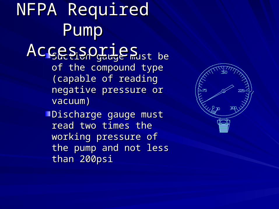
Suction gauge must be of Suction gauge must be of the compound type (capable the compound type (capable of reading negative pressure of reading negative pressure or vacuum)or vacuum)
Discharge gauge must read Discharge gauge must read two times the working two times the working pressure of the pump and pressure of the pump and not less than 200psinot less than 200psi
NFPA Required NFPA Required Pump AccessoriesPump Accessories
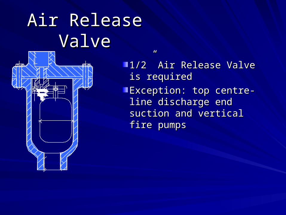
1/2” Air Release Valve is 1/2” Air Release Valve is required required
Exception: top centre-line Exception: top centre-line discharge end suction and discharge end suction and vertical fire pumpsvertical fire pumps
Air Release ValveAir Release Valve

3/4” up to 2500usgpm3/4” up to 2500usgpm
1” over 3000usgpm1” over 3000usgpm
Should be set between the Should be set between the maximum suction pressure and maximum suction pressure and minimum suction pressure plus minimum suction pressure plus the closed valve pressure of the the closed valve pressure of the pumppump
Piped before the fire pump Piped before the fire pump discharge check valvedischarge check valve
Casing Relief ValveCasing Relief Valve

• Suction OS&Y Gate Valve
• Discharge Butterfly Valve
• Both must be supervised
• Discharge Butterfly Valve Installed after “Test Tee” and pressure sensing line
Isolation ValvesIsolation Valves

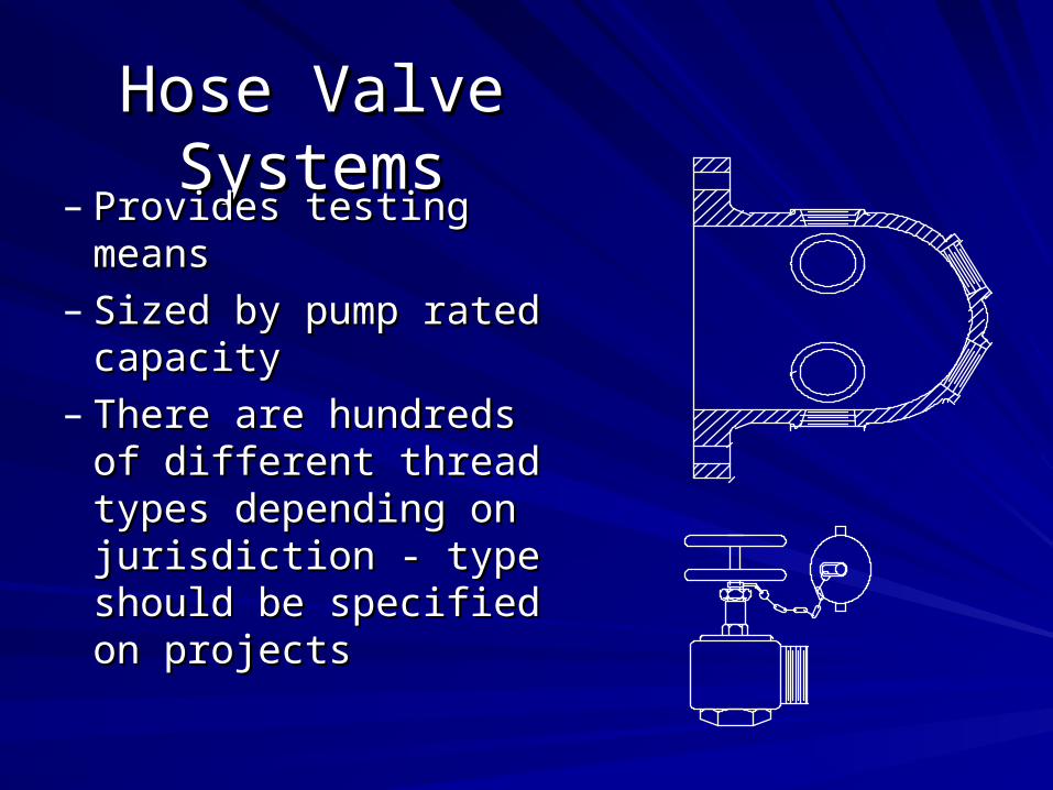
Hose Valve SystemsHose Valve Systems
– Provides testing meansProvides testing means– Sized by pump rated Sized by pump rated
capacitycapacity– There are hundreds of There are hundreds of
different thread types different thread types depending on jurisdiction depending on jurisdiction - type should be - type should be specified on projectsspecified on projects


Flow MetersFlow Meters– Does not replace a hose valve systemDoes not replace a hose valve system– Flow meters must be listed for fire protection serviceFlow meters must be listed for fire protection service– Gauge reading is a minimum of 175% the pump rated flowGauge reading is a minimum of 175% the pump rated flow– Provides a testing means without wasting waterProvides a testing means without wasting water– Flow meter is installed in bypass back to suctionFlow meter is installed in bypass back to suction– Must be installed with isolation valves per manufacturer’s Must be installed with isolation valves per manufacturer’s
specificationsspecifications– RULE OF THUMB:RULE OF THUMB:
Annular Type - 10Ø upstream - 5Ø downstreamAnnular Type - 10Ø upstream - 5Ø downstreamVenturi Type - 7Ø upstream - 5Ø downstreamVenturi Type - 7Ø upstream - 5Ø downstream


Main Relief Valves Main Relief Valves and Waste Conesand Waste Cones
– Sized by pump rated Sized by pump rated capacitycapacity
– Spring or pilot operatedSpring or pilot operated– Waste cone provides Waste cone provides
visibility of flow through visibility of flow through the valvethe valve
– When it is used:When it is used:
11 ( (Diesel driven systemsDiesel driven systems
22 ( (Electric systemsElectric systems??? ???

Main Relief Valve - Main Relief Valve - Diesel PumpsDiesel Pumps
1000
30
165
130
psi
GPM
Shutoff Head @ Rated Speed
20
1500
Shutoff Head @ 10%
Overspeed179

Main Relief Valves Main Relief Valves and Waste Conesand Waste Cones
– Recommended on all diesel driven Recommended on all diesel driven systemssystems
– Not required on diesel if maximum Not required on diesel if maximum supply pressure plus 1.21 x closed supply pressure plus 1.21 x closed valve pressure does not exceed valve pressure does not exceed system pressure ratingsystem pressure rating
– NFPA allows piping back to suction - NFPA allows piping back to suction - NOT recommendedNOT recommended
– Relief valve should be set below Relief valve should be set below maximum pressure rating of the maximum pressure rating of the systemsystem

Main Relief Valve - Main Relief Valve - Electric PumpsElectric Pumps
1000
60
180
130
psi
GPM
Max Shutoff Head
20
1500
Rated Head

Misinterpreted Code Misinterpreted Code RequirementRequirement
– Devices in the discharge piping - main Devices in the discharge piping - main relief or pressure reducing valves should relief or pressure reducing valves should only be installed where absolutely only be installed where absolutely necessarynecessary
– Valves introduce a failure mode and Valves introduce a failure mode and should only be used when requiredshould only be used when required

Piping, Relief Valves, Metering Devices, and Piping, Relief Valves, Metering Devices, and Hose Valves should be sized according to Hose Valves should be sized according to
Table 2-20 on Page 20-13Table 2-20 on Page 20-13..
NFPA Fitting SizingNFPA Fitting Sizing

NFPA Required NFPA Required Pump AccessoriesPump AccessoriesFire Pump Rating
GPM (L/s)Suction
Size (in.)DischargeSize (in.)
Relief ValveSize (in.)
Relief ValveDischarge
(in.)
Flow MeterSize (in.)
Number &Size of Hose
Valves
Hose ValveManifoldSize (in.)
25 (95) 1 1 ¾ 1 1¼ 1 - 1½ “ 150 (189) 1½ 1¼ 1¼ 1½ 2 1 - 1½ “ 1½100 (379) 2 2 1½ 2 2½ 1 - 2½ “ 2½150 (568) 2½ 2½ 2 2½ 3 1 - 2½ “ 2½200 (757) 3 3 2 2½ 3 1 - 2½ “ 2½
250 (946) 3½ 3 2 2½ 3½ 1 - 2½ “ 3300 (1136) 4 4 2½ 3½ 3½ 2 - 2½ “ 3400 (1514) 4 4 3 5 4 2 - 2½ “ 4450 (1703) 5 5 3 5 4 2 - 2½ “ 4500 (1892) 5 5 3 5 5 2 - 2½ “ 4
750 (2839) 6 6 4 6 5 3 - 2½ “ 61000 (3785) 8 6 4 8 6 4 - 2½ “ 61250 (4731) 8 8 6 8 6 6 - 2½ “ 81500 (5677) 8 8 6 8 8 6 - 2½ “ 82000 (7570) 10 10 6 10 8 6 - 2½ “ 8
2500 (9462) 10 10 6 10 8 8 - 2½ “ 103000 (11,355) 12 12 8 12 8 12 - 2½ “ 10

Pressure Maintenance Pump Pressure Maintenance Pump (Jockey)(Jockey)
Every system has a normal leakage rate Every system has a normal leakage rate that will result in a pressure dropthat will result in a pressure drop
Jockey Pump will maintain the pressure in Jockey Pump will maintain the pressure in the systemthe system
This will prevent the main fire pump from This will prevent the main fire pump from starting for minor leaksstarting for minor leaks

Jockey PumpsJockey Pumps
Jockey (pressure maintenance) pumps and Jockey (pressure maintenance) pumps and jockey controllers need not be listed for fire jockey controllers need not be listed for fire protection service.protection service.
““The primary or standby fire pump shall not be The primary or standby fire pump shall not be used as a pressure maintenance pump.”used as a pressure maintenance pump.”
A jockey pump should be sized such that it A jockey pump should be sized such that it CANNOT meet the flow demand of a single CANNOT meet the flow demand of a single sprinkler fixture.sprinkler fixture.

Jockey Pump SizingJockey Pump Sizing
Jockey pumps should be sized for 1% of Jockey pumps should be sized for 1% of the flow of the main fire pumpthe flow of the main fire pump
Jockey pumps should be sized to provide Jockey pumps should be sized to provide 10psi more pressure than the main fire 10psi more pressure than the main fire pumppump
Jockey pump should be sized so that it Jockey pump should be sized so that it cannot meet the demand of the lowest cannot meet the demand of the lowest flow fire protection fitting in the systemflow fire protection fitting in the system

Fire Pump OperationFire Pump Operation
– Fire pumps are designed to start on a Fire pumps are designed to start on a pressure switch settingpressure switch setting
– Some fire pumps can be started automatically Some fire pumps can be started automatically based on a deluge valve opening, or a remote based on a deluge valve opening, or a remote signalsignal
– The pressure sensing line is the lifeline for the The pressure sensing line is the lifeline for the fire protection systemfire protection system

Fire Pump OperationFire Pump Operation– Pressure switches should be rated for maximum pressure Pressure switches should be rated for maximum pressure
conditionsconditions– Sensing lines must be 1/2” non-ferrous (copper) with two Sensing lines must be 1/2” non-ferrous (copper) with two
check valves with a 3/32” hole drilled in the flappercheck valves with a 3/32” hole drilled in the flapper– Check valves are for damping of pressure when the pump Check valves are for damping of pressure when the pump
starts to protect the pressure switchstarts to protect the pressure switch– Check valves are installed 5 feet apart and must open on a Check valves are installed 5 feet apart and must open on a
pressure drop in the sensing line pressure drop in the sensing line – Check valves close when the pump startsCheck valves close when the pump starts– Jockey pump and fire pump sensing lines must be separateJockey pump and fire pump sensing lines must be separate


System gradually looses pressure
50
90 95100110
Jockey startFire Pump start
Stop PointPump shutoff
psi
Time period
boost
Fire Pump OperationFire Pump Operation

Critical New Code Requirements Critical New Code Requirements (2003)(2003)
– Extensive changes to NFPA20 including Extensive changes to NFPA20 including chapter numberschapter numbers
– Fire pump sizing will move from the Appendix Fire pump sizing will move from the Appendix to the main text of the codeto the main text of the code
– Greater clarity on devices in the discharge Greater clarity on devices in the discharge pipingpiping
– Provisions for the acceptance of electronic Provisions for the acceptance of electronic speed governors on diesel enginesspeed governors on diesel engines
– Reference to NEMA ICS 14-2001 as Appendix Reference to NEMA ICS 14-2001 as Appendix B (Application Guide for Electric Fire Pump B (Application Guide for Electric Fire Pump Controllers)Controllers)
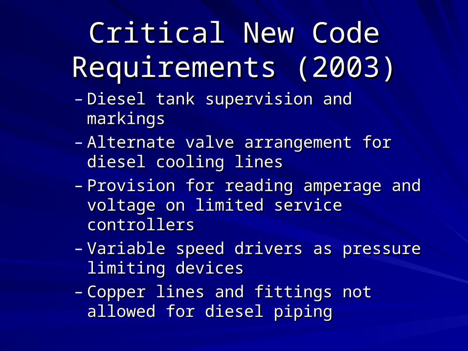
Critical New Code Requirements Critical New Code Requirements (2003)(2003)
– Diesel tank supervision and markingsDiesel tank supervision and markings– Alternate valve arrangement for diesel Alternate valve arrangement for diesel
cooling linescooling lines– Provision for reading amperage and Provision for reading amperage and
voltage on limited service controllersvoltage on limited service controllers– Variable speed drivers as pressure limiting Variable speed drivers as pressure limiting
devicesdevices– Copper lines and fittings not allowed for Copper lines and fittings not allowed for
diesel pipingdiesel piping

Typical System Performance - 500gpm, 160psiincluding 85psi Suction Pressure
100
110
120
130
140
150
160
170
180
190
200
210
220
0 50 100 150 200 250 300 350 400 450 500 550 600 650 700 750 800
Flow - GPM
Hea
d -
PS
I
2700
2800
2900
3000
3100
3200
3300
3400
3500
3600
RP
M
PLT OFF 85psi SuctPLT ON 85psi SuctPLT ON 85psi RPMPLT OFF 85psi RPM
System PressureLimit
Pressure LimitingControl Range
RPM
System Pressure
RPM

FIRE PUMP CONTROLLERSFIRE PUMP CONTROLLERS
Diesel or ElectricDiesel or Electric
Full Service or Limited ServiceFull Service or Limited Service
HP of the motorHP of the motor
Voltage of the installationVoltage of the installation
Withstand ratingWithstand rating
Starting methodStarting method

Across the Line Across the Line – Limited Service - Under 30hpLimited Service - Under 30hp– Full ServiceFull Service
Reduced VoltageReduced Voltage– Auto TransformerAuto Transformer– Wye Delta - Special Motor RequiredWye Delta - Special Motor Required– Part Winding - Special Motor Part Winding - Special Motor
RequiredRequired– Primary ResistorPrimary Resistor
CONTROLLER STARTING METHODCONTROLLER STARTING METHOD

CONTROLLER STARTING METHODCONTROLLER STARTING METHOD600
% of FullLoad
Current
Full speed
390
252200
FULL VOLTAGE
PRIM. RESISTOR
PART WINDING
AUTO-TRANSFORMER
WYE DELTA
FULL LOAD CURRENT
420
100

AUTOMATIC TRANSFER AUTOMATIC TRANSFER SWITCHESSWITCHES
What is it?What is it?– An additional controller used An additional controller used
in case of a power failurein case of a power failure
Why use it?Why use it?– To transfer the power to To transfer the power to
another source (generator another source (generator or diesel)or diesel)
When to use it?When to use it?– If Authorities Require OneIf Authorities Require One– If Power Source not ReliableIf Power Source not Reliable
Serve Three Basic FunctionsServe Three Basic Functions::• Start the Diesel Engine in an emergencyStart the Diesel Engine in an emergency• Monitor the Operation and Condition of the Monitor the Operation and Condition of the
Diesel EngineDiesel Engine• Keep the batteries chargedKeep the batteries charged
DIESEL CONTROLLERSDIESEL CONTROLLERS

Diesel Can be Started by Three MethodsDiesel Can be Started by Three Methods::• Pressure Switch (In the Automatic Mode)Pressure Switch (In the Automatic Mode)• Pressure Switch (In the Test Mode)Pressure Switch (In the Test Mode)• Manual Cranking (In the Automatic or Manual Manual Cranking (In the Automatic or Manual
Mode)Mode)
Starting sequenceStarting sequence::• Alternating cranking sequenceAlternating cranking sequence• Six cranks every 30 seconds until diesel startsSix cranks every 30 seconds until diesel starts• If diesel fails to start, an alarm is activatedIf diesel fails to start, an alarm is activated
DIESEL CONTROLLERSDIESEL CONTROLLERS

Diesel Can be Stopped by Two MethodsDiesel Can be Stopped by Two Methods::• Manually by Pushing the Stop ButtonManually by Pushing the Stop Button• Automatically after 30 minutes during weekly Automatically after 30 minutes during weekly
testtest
Overspeed shutdown:Overspeed shutdown:• A diesel fire pump will shut down in an A diesel fire pump will shut down in an
emergency condition if the diesel operates emergency condition if the diesel operates more than 20% faster than the rated speedmore than 20% faster than the rated speed
DIESEL CONTROLLERSDIESEL CONTROLLERS
Diesel Controller AlarmsDiesel Controller Alarms• Battery and Charger FailuresBattery and Charger Failures• Diesel operating condition (High Coolant Diesel operating condition (High Coolant
Temperature, Low Oil Pressure, Overspeed, Temperature, Low Oil Pressure, Overspeed, Failure to Start)Failure to Start)
• Contacts for remote indication of alarm Contacts for remote indication of alarm conditionsconditions
• Optional Pump Room Alarms (Low suction Optional Pump Room Alarms (Low suction pressure, flow meter on, Main Relief Valve pressure, flow meter on, Main Relief Valve open, Low/High Pump Room temperature, Low open, Low/High Pump Room temperature, Low fuel level, Others )fuel level, Others )
DIESEL CONTROLLERSDIESEL CONTROLLERS

Battery Charging Systems:Battery Charging Systems:• One charger for each set of batteriesOne charger for each set of batteries• Chargers are capable of fully charging the Chargers are capable of fully charging the
batteries in 24 hoursbatteries in 24 hours• Batteries remain in an overcharged Batteries remain in an overcharged
conditioncondition
DIESEL CONTROLLERSDIESEL CONTROLLERS

Pump MaintenancePump MaintenancePump acceptance tests are defined in NFPA20 Chapter 11Pump acceptance tests are defined in NFPA20 Chapter 11
Inspection and maintenance are defined in NFPA25 Inspection and maintenance are defined in NFPA25 Chapter 5Chapter 5
Seals and bearings are the highest maintenance item for a Seals and bearings are the highest maintenance item for a pumppump
The packing should be checked and adjusted each time the The packing should be checked and adjusted each time the pump is testedpump is tested
As fire pumps do not run often, bearings should be checked As fire pumps do not run often, bearings should be checked for cleanliness and to ensure that adequate oil or grease for cleanliness and to ensure that adequate oil or grease has been applied (depending on the type of bearing)has been applied (depending on the type of bearing)
Motor bearings should also be checkedMotor bearings should also be checked

Thank youThank you!!