
Nexus 7000 Site Prep
56
Send document comments to [email protected] Americas Headquarters Cisco Systems, Inc. 170 West Tasman Drive San Jose, CA 95134-1706 USA http://www.cisco.com Tel: 408 526-4000 800 553-NETS (6387) Fax: 408 527-0883 Cisco Nexus 7000 Series Site Preparation Guide October 29, 2011 Text Part Number: OL-23070-05
Transcript of Nexus 7000 Site Prep
Se nd do cume nt c ommen ts t o nex us7k -d oc fee dba ck@c i sc o . co m
Americas HeadquartersCisco Systems, Inc.170 West Tasman DriveSan Jose, CA 95134-1706 USAhttp://www.cisco.comTel: 408 526-4000
800 553-NETS (6387)Fax: 408 527-0883
Cisco Nexus 7000 Series Site Preparation GuideOctober 29, 2011
Text Part Number: OL-23070-05

Se nd do cume nt c ommen ts t o nex us7k -d oc fee dba ck@c i sc o . co m
HE SPECIFICATIONS AND INFORMATION REGARDING THE PRODUCTS IN THIS MANUAL ARE SUBJECT TO CHANGE WITHOUT NOTICE. ALL STATEMENTS, INFORMATION, AND RECOMMENDATIONS IN THIS MANUAL ARE BELIEVED TO BE ACCURATE BUT ARE PRESENTED WITHOUT WARRANTY OF ANY KIND, EXPRESS OR IMPLIED. USERS MUST TAKE FULL RESPONSIBILITY FOR THEIR APPLICATION OF ANY PRODUCTS.
THE SOFTWARE LICENSE AND LIMITED WARRANTY FOR THE ACCOMPANYING PRODUCT ARE SET FORTH IN THE INFORMATION PACKET THAT SHIPPED WITH THE PRODUCT AND ARE INCORPORATED HEREIN BY THIS REFERENCE. IF YOU ARE UNABLE TO LOCATE THE SOFTWARE LICENSE OR LIMITED WARRANTY, CONTACT YOUR CISCO REPRESENTATIVE FOR A COPY.
The following information is for FCC compliance of Class A devices: This equipment has been tested and found to comply with the limits for a Class A digital device, pursuant to part 15 of the FCC rules. These limits are designed to provide reasonable protection against harmful interference when the equipment is operated in a commercial environment. This equipment generates, uses, and can radiate radio-frequency energy and, if not installed and used in accordance with the instruction manual, may cause harmful interference to radio communications. Operation of this equipment in a residential area is likely to cause harmful interference, in which case users will be required to correct the interference at their own expense.
The following information is for FCC compliance of Class B devices: The equipment described in this manual generates and may radiate radio-frequency energy. If it is not installed in accordance with Cisco’s installation instructions, it may cause interference with radio and television reception. This equipment has been tested and found to comply with the limits for a Class B digital device in accordance with the specifications in part 15 of the FCC rules. These specifications are designed to provide reasonable protection against such interference in a residential installation. However, there is no guarantee that interference will not occur in a particular installation.
Modifying the equipment without Cisco’s written authorization may result in the equipment no longer complying with FCC requirements for Class A or Class B digital devices. In that event, your right to use the equipment may be limited by FCC regulations, and you may be required to correct any interference to radio or television communications at your own expense.
You can determine whether your equipment is causing interference by turning it off. If the interference stops, it was probably caused by the Cisco equipment or one of its peripheral devices. If the equipment causes interference to radio or television reception, try to correct the interference by using one or more of the following measures:
• Turn the television or radio antenna until the interference stops.
• Move the equipment to one side or the other of the television or radio.
• Move the equipment farther away from the television or radio.
• Plug the equipment into an outlet that is on a different circuit from the television or radio. (That is, make certain the equipment and the television or radio are on circuits controlled by different circuit breakers or fuses.)
Modifications to this product not authorized by Cisco Systems, Inc. could void the FCC approval and negate your authority to operate the product.
The Cisco implementation of TCP header compression is an adaptation of a program developed by the University of California, Berkeley (UCB) as part of UCB’s public domain version of the UNIX operating system. All rights reserved. Copyright © 1981, Regents of the University of California.
NOTWITHSTANDING ANY OTHER WARRANTY HEREIN, ALL DOCUMENT FILES AND SOFTWARE OF THESE SUPPLIERS ARE PROVIDED “AS IS” WITH ALL FAULTS. CISCO AND THE ABOVE-NAMED SUPPLIERS DISCLAIM ALL WARRANTIES, EXPRESSED OR IMPLIED, INCLUDING, WITHOUT LIMITATION, THOSE OF MERCHANTABILITY, FITNESS FOR A PARTICULAR PURPOSE AND NONINFRINGEMENT OR ARISING FROM A COURSE OF DEALING, USAGE, OR TRADE PRACTICE.
IN NO EVENT SHALL CISCO OR ITS SUPPLIERS BE LIABLE FOR ANY INDIRECT, SPECIAL, CONSEQUENTIAL, OR INCIDENTAL DAMAGES, INCLUDING, WITHOUT LIMITATION, LOST PROFITS OR LOSS OR DAMAGE TO DATA ARISING OUT OF THE USE OR INABILITY TO USE THIS MANUAL, EVEN IF CISCO OR ITS SUPPLIERS HAVE BEEN ADVISED OF THE POSSIBILITY OF SUCH DAMAGES.
Cisco and the Cisco Logo are trademarks of Cisco Systems, Inc. and/or its affiliates in the U.S. and other countries. A listing of Cisco's trademarks can be found at www.cisco.com/go/trademarks. Third party trademarks mentioned are the property of their respective owners. The use of the word partner does not imply a partnership relationship between Cisco and any other company. (1005R)
Any Internet Protocol (IP) addresses used in this document are not intended to be actual addresses. Any examples, command display output, and figures included in the document are shown for illustrative purposes only. Any use of actual IP addresses in illustrative content is unintentional and coincidental.
Any Internet Protocol (IP) addresses used in this document are not intended to be actual addresses. Any examples, command display output, and figures included in the document are shown for illustrative purposes only. Any use of actual IP addresses in illustrative content is unintentional and coincidental.
Cisco Nexus 7000 Series Site Preparation Guide© 2008-2011 Cisco Systems, Inc. All rights reserved.
Se nd do cume nt c ommen ts t o nex us7k -d oc fee dba ck@c i sc o . co m
iiiCisco Nexus 7000 Series Site Preparation Guide
OL-23070-05
C O N T E N T S
New and Changed Information v
Preface vii
Audience vii
Document Organization vii
Document Conventions vii
Related Documentation viii
Obtaining Documentation and Submitting a Service Request viii
C H A P T E R 1 Overview 1-1
C H A P T E R 2 Preparing the Site 2-1
Information About the Site Requirements 2-1
Temperature 2-2
Humidity 2-2
Altitude 2-3
Dust and Particles 2-3
Corrosion 2-3
Electromagnetic and Radio Frequency Interference 2-3
Shock and Vibration 2-4
Grounding 2-4
Power Source 2-4
C H A P T E R 3 Technical Specifications 3-1
Environmental Specifications for Cisco Nexus 7000 Series Switches 3-1
Physical Specifications for the Cisco Nexus 7000 Series Chassis 3-2
Power Specifications for Cisco Nexus 7000 Series Switches 3-5
Power Requirements for Switch Components 3-5
Power Supply Configuration Modes 3-6
Power Supply Cable Specifications 3-9
Chassis Clearances 3-15
Cisco Nexus 7009 Chassis Clearances 3-15
Cisco Nexus 7010 Chassis Clearances 3-16
Se nd do cume nt c ommen ts t o nex us7k -d oc fee dba ck@c i sc o . co m
Contents
ivCisco Nexus 7000 Series Site Preparation Guide
OL-23070-05
Cisco Nexus 7018 Chassis Clearances 3-16
Facility Cooling Requirements 3-16
Chassis Airflow 3-16
A P P E N D I X A Site Preparation and Maintenance Records A-1
Site Preparation Checklist A-1
Contact and Site Information A-3
Chassis and Module Information A-3
A P P E N D I X B Cabinet and Rack Requirements B-1
General Requirements for Cabinets and Racks B-1
Cabinet and Rack Vendors B-3
I N D E X
Se nd do cume nt c ommen ts t o nex us7k -d oc fee dba ck@c i sc o . co m
vCisco Nexus 7000 Series Site Preparation Guide
OL-23070-05
New and Changed Information
This chapter provides release-specific information for each new and changed feature in the Cisco Nexus 7000 Series Site Preparation Guide. The latest version of this document is available at the following Cisco website:
http://www.cisco.com/en/US/docs/switches/datacenter/hw/nexus7000/site_prep/guide/nexus7k_siteprep_book.html
Table 1 summarizes the new and changed features for the Cisco Nexus 7000 Series Site Preparation Guide, and tells you where they are documented.
Table 1 New and Changed Features for Release 6.0(1)
Feature DescriptionChanged in Release Where Documented
48-port 1- and 10-Gigabit Ethernet SFP+ I/O module
Introduced the F2 48-port 1- and 10-Gigabit Ethernet SFP+ I/O module for use with Series 2 fabric modules on the Cisco Nexus 7000 Series switches.
6.0(1) Chapter 1, “Overview”
Chapter 3, “Technical Specifications”
Series 2 fabric modules for Cisco Nexus 7010 and 7018
Introduced the Series 2 fabric module for the Cisco Nexus 7010 and 7018 switches (the Cisco 7009 switch was introduced earlier with its own Series 2 fabric module).
6.0(1) Chapter 1, “Overview”
Chapter 3, “Technical Specifications”
Cisco Nexus 7010 and 7018 chassis
Modified the rear clearance from 30 inches (76 cm) to 26 inches (66 cm)
6.0(1) Chapter 3, “Technical Specifications”

Se nd do cume nt c ommen ts t o nex us7k -d oc fee dba ck@c i sc o . co m
viCisco Nexus 7000 Series Site Preparation Guide
OL-23070-05
New and Changed Information

Se nd do cume nt c ommen ts t o nex us7k -d oc fee dba ck@c i sc o . co m
viiCisco Nexus 7000 Series Site Preparation Guide
OL-23070-05
Preface
This preface describes the audience, organization, and conventions of the Cisco Nexus 7000 Series Site Preparation Guide. It also provides information on how to obtain related documentation.
AudienceThis guide is intended for anyone who plans the facilities, including space, floor weighting, power, cooling, cabling, delivery, and storage for the installation of the Cisco Nexus 7000 Series switches.
Document OrganizationThis document is organized into the following chapters:
Document ConventionsNotes use the following conventions:
Note Means reader take note. Notes contain helpful suggestions or references to material not covered in the publication.
Chapter Description
Chapter 1, “Overview” Provides an overview of the Cisco Nexus 7000 Series and its switches.
Chapter 2, “Preparing the Site” Describes the basic site requirements for installing the Cisco Nexus 7000 Series switches.
Chapter 3, “Technical Specifications” Describes the technical specifications for the Cisco Nexus 7000 Series switches.
Chapter A, “Site Preparation and Maintenance Records”
Provides a site planning list to prepare your site for the Cisco Nexus 7000 Series switches.
Chapter B, “Cabinet and Rack Requirements” Describes the cabinet and rack requirements for the Cisco Nexus 7000 Series switches.

Se nd do cume nt c ommen ts t o nex us7k -d oc fee dba ck@c i sc o . co m
viiiCisco Nexus 7000 Series Site Preparation Guide
OL-23070-05
Preface
Caution Means reader be careful. In this situation, you might do something that could result in equipment damage or loss of data.
Related DocumentationCisco Nexus 7000 Series documentation includes the following documents:
Hardware Documents
Cisco Nexus 7000 Series Site Preparation Guide
Cisco Nexus 7000 Series Hardware Installation and Reference Guide
Cisco Nexus 7000 Series Regulatory Compliance and Safety Information
Cisco Nexus 7000 Series Connectivity Management Processor Configuration Guide
Software Documents
The Cisco Nexus 7000 Series switches ship with the Cisco NX-OS software. You can find software documentation for the Cisco NX-OS software at the following URL:
http://www.cisco.com/en/US/products/ps9402/tsd_products_support_series_home.html
The Cisco Data Center Network Manager (DCNM) supports the Cisco Nexus 7000 Series. You can find documentation for DCNM at the following URL:
http://www.cisco.com/en/US/products/ps9369/tsd_products_support_series_home.html
Obtaining Documentation and Submitting a Service RequestFor information on obtaining documentation, submitting a service request, and gathering additional information, see the monthly What’s New in Cisco Product Documentation, which also lists all new and revised Cisco technical documentation, at:
http://www.cisco.com/en/US/docs/general/whatsnew/whatsnew.html
Subscribe to the What’s New in Cisco Product Documentation as a Really Simple Syndication (RSS) feed and set content to be delivered directly to your desktop using a reader application. The RSS feeds are a free service and Cisco currently supports RSS version 2.0.

C H A P T E R
Se nd do cume nt c ommen ts t o nex us7k -d oc fee dba ck@c i sc o . co m
1-1Cisco Nexus 7000 Series Site Preparation Guide
OL-23070-05
1Overview
This chapter provides an overview of the Cisco Nexus 7000 Series switches, which support end-to-end data center connectivity, consolidating IP, storage, and interprocess communication (IPC) networks onto a single Ethernet fabric.
The Cisco Nexus 7000 Series includes the following switches:
• Cisco Nexus 7009 switch—Provides nine slots that include two supervisor modules and up to seven I/O modules with 8.8 Terrabytes per second (Tbps) of forwarding capacity. You can access the supervisor, I/O module, and fabric modules from the front, and you can access the power supply and fan modules from the rear. This switch uses side-to-side airflow.
• Cisco Nexus 7010 switch—Provides 10 slots that include two supervisor modules and up to eight I/O modules with 4.1 Tbps of forwarding capacity. You can access the supervisor and I/O modules from the front, and you can access the fabric modules, power supply, and fan modules from the rear. This switch uses front-to-back airflow
• Cisco Nexus 7018 switch—Provides 18 slots that include two supervisor modules and up to 16 I/O modules with 7.8 Tbps of forwarding capacity. You can access the supervisor and I/O modules from the front, and you can access the fabric, power supply, and fan modules from the rear. This switch uses side-to-side airflow.
Both switches use the same supervisor modules, I/O modules, and power supply units (AC and DC models). The fan trays and fabric modules are unique to each type of chassis. To compare the features of these two switches, see Table 1-1.
Table 1-1 Cisco Nexus 7000 Series Switch Features
Feature Cisco Nexus 7009 Cisco Nexus 7010 1 Cisco Nexus 7018 1
Chassis 9-slot chassis 10-slot chassis 18-slot chassis
Supervisor Modules
1 to 2 modules (N7K-SUP1) shipped in the chassis.

Se nd do cume nt c ommen ts t o nex us7k -d oc fee dba ck@c i sc o . co m
1-2Cisco Nexus 7000 Series Site Preparation Guide
OL-23070-05
Chapter 1 Overview
For information about preparing your site for the Nexus 7000 Series switches, see Chapter 2, “Preparing the Site.”
I/O Modules 1 to 7 modules shipped in the chassis.
1 to 8 modules shipped in the chassis.
1 to 16 modules shipped in the chassis.
• 48-port 10/100/1000 Ethernet (N7K-M148GT-11)
• 48-port 10/100/1000 Ethernet (N7K-M148GT-11L)
• 48-port 1-Gigabit Ethernet (N7K-M148GS-11)
• 48-port 1-Gigabit Ethernet XL (N7K-M148GS-11L)
• 48-port 1- and 10-Gigabit Ethernet (N7K-F248XP-25)
• 32-port 10-Gigabit Ethernet (N7K-M132XP-12)
• 32-port 10-Gigabit Ethernet XL (N7K-M132XP-12L)
• 32-port 1- and 10-Gigabit Ethernet (N7K-F132XP-15)
• 8-port 10-Gigabit Ethernet XL (N7K-M108X2-12L)
Fan Tray 1 fan tray (N7K-C7009-FAN) shipped in chassis.
— 2 fan trays (N7K-C7018-FAN) shipped in the chassis.
System Fan Tray
— 2 fan trays (N7K-C7010-FAN-S) shipped in the chassis.
—
Fabric Fan Tray
— 2 fan trays (N7K-C7010-FAN-F) shipped in the chassis.
—
Fabric-1 Modules
— 3 to 5 modules (N7K-C7010-FAB-1) shipped in the chassis. These modules deliver 230 Gbps per slot for up to 4.1 Tbps of forwarding capacity.
3 to 5 modules ((N7K-C7018-FAB-1) shipped in the chassis. These modules deliver 230 Gbps per slot for up to 7.8 Tbps of forwarding capacity.
Fabric-2 Modules
3 to 5 modules (N7K-C7009-FAB-2) shipped in the chassis. These modules deliver 550 Gbps per slot for up to 8.8 Tbps of forwarding capacity.
3 to 5 modules (N7K-C7010-FAB-2). These modules deliver 550 Gbps per slot for up to 8.8 Tbps of forwarding capacity.
3 to 5 modules (N7K-C7018-FAB-2). These modules deliver 550 Gbps per slot for up to 8.8 Tbps of forwarding capacity.
Power Supplies
1 or 2 power supply units shipped with the chassis but boxed separately.
2 to 3 power supply units shipped with the chassis but boxed separately.
2 to 4 power supply units shipped with the chassis but boxed separately.
• 6-kW AC power supply unit (N7K-AC-6.0KW)
• 7.5-kW AC power supply unit (N7K-AC-7.5KW-INT and N7K-AC-7.5KW-US)
• 6-kW DC power supply unit (N7K-DC-6.0KW)
DC Power Interface Unit
1 or 2 used when the DC power source is more than 15 feet (4.6 m) away from the DC power supply units.
1. The quantity of supervisor, I/O, and fabric modules, and power supply units shipped with the chassis will vary depending on your order.
Table 1-1 Cisco Nexus 7000 Series Switch Features (continued)
Feature Cisco Nexus 7009 Cisco Nexus 7010 1 Cisco Nexus 7018 1

Se nd do cume nt c ommen ts t o nex us7k -d oc fee dba ck@c i sc o . co m
1-3Cisco Nexus 7000 Series Site Preparation Guide
OL-23070-05
Chapter 1 Overview
For information about installing the Cisco Nexus 7000 Series switches, see the Cisco Nexus 7000 Series Hardware Installation and Reference Guide. For translations of the warnings in that guide, see the Cisco Nexus 7000 Series Regulatory Compliance and Safety Information document.

Se nd do cume nt c ommen ts t o nex us7k -d oc fee dba ck@c i sc o . co m
1-4Cisco Nexus 7000 Series Site Preparation Guide
OL-23070-05
Chapter 1 Overview

C H A P T E R
Se nd do cume nt c ommen ts t o nex us7k -d oc fee dba ck@c i sc o . co m
2-1Cisco Nexus 7000 Series Site Preparation Guide
OL-23070-05
2Preparing the Site
This chapter describes the basic site requirements that you should be aware of as you prepare to install your Cisco Nexus 7000 Series switches.
This chapter includes the following sections:
• Information About the Site Requirements, page 2-1
• Temperature, page 2-2
• Humidity, page 2-2
• Altitude, page 2-3
• Dust and Particles, page 2-3
• Corrosion, page 2-3
• Electromagnetic and Radio Frequency Interference, page 2-3
• Shock and Vibration, page 2-4
• Grounding, page 2-4
• Power Source, page 2-4
Information About the Site RequirementsEnvironmental factors can adversely affect the performance and life span of your switch. The Cisco Nexus 7000 Series switches require a dry, clean, well-ventilated, and air-conditioned environment. To ensure normal operation, you must maintain ambient airflow. If the airflow is blocked or restricted, or if the intake air is too warm, an overtemperature condition can occur and the environmental monitor on the switch will shut down to protect the switch components.
In a 42-rack unit (RU) rack, you can mount up to three Cisco Nexus 7009 chassis or two Cisco Nexus 7010 chassis or one Cisco Nexus 7018 chassis. You must also allow enough room in front for loading the chassis using a mechanical lift and enough room in the rear for removing the switch components. When mounting the Cisco Nexus 7000 Series chassis in a rack with other equipment, ensure that the exhaust from the other equipment does not blow into the air intake vent of the Cisco Nexus 7000 Series chassis. If your site has hot and cold aisles, align the rack or cabinet air intake to a cold aisle and exhaust to a hot aisle.

Se nd do cume nt c ommen ts t o nex us7k -d oc fee dba ck@c i sc o . co m
2-2Cisco Nexus 7000 Series Site Preparation Guide
OL-23070-05
Chapter 2 Preparing the SiteTemperature
TemperatureTemperature extremes can cause the Cisco Nexus 7000 Series switches to operate at reduced efficiency and cause a variety of problems, including premature aging, failure of chips, and failure of switches. In addition, extreme temperature fluctuations can cause chips to become loose in their sockets. The Cisco Nexus 7000 Series switches should operate in an environment that is not colder than 32°F (0°C) or hotter than 104°F (40°C).
To control the switch temperature, you must make sure that the switch has adequate airflow, as follows:
• The Cisco Nexus 7009 switch requires side-to-side airflow, which requires that you leave at least 11 inches (27.9 cm) free on both sides of the chassis (or 22 inches [55.8 cm] between two Cisco Nexus 7009 or 7018 switches]), and you must be sure that cables do not block the airflow from the lower right front of the chassis (for more information, see the “Chassis Clearances” section on page 3-15).
• The Cisco Nexus 7010 switch requires front-to-back airflow, which requires that you not block the front air intake or the rear exhaust areas (for more information, see the “Chassis Clearances” section on page 3-15).
• The Cisco Nexus 7018 switch requires side-to-side airflow, which requires that you leave at least 11 inches (27.9 cm) free on both sides of the chassis (or 22 inches [55.8 cm] between two Cisco Nexus 7009 or 7018 switches]), and you must be sure that cables do not block the airflow from the lower right front of the chassis (for more information, see the “Chassis Clearances” section on page 3-15).
To prevent overheating and to minimize the energy spent to cool the Cisco Nexus 7000 Series switch, do not place the chassis next to a heat source of any kind, including heating vents during cold weather.
Adequate ventilation is particularly important if you are operating a Cisco Nexus 7000 Series switch at high altitudes. Make sure that all slots and openings on the chassis remain unobstructed, especially the fan vents. Clean the installation site at regular intervals to avoid buildup of dust and debris, which can cause a switch to overheat.
If the Cisco Nexus 7000 Series switch is exposed to abnormally cold temperatures, allow a 2-hour warm-up period to bring it up to a normal operating temperature before you turn the switch on.
Caution If you do not allow a 2-hour warm-up period when temperatures are abnormally cold, you can damage the internal components.
Note The Cisco Nexus 7000 Series switches are equipped with internal air temperature sensors that trigger a minor alarm at 104°F (40°C) and a major alarm at 131°F (55°C).
HumidityHigh humidity can cause moisture to seep into the Cisco Nexus 7000 Series switches. Moisture can cause corrosion of internal components and degradation of properties such as electrical resistance, thermal conductivity, physical strength, and size. The Cisco Nexus 7000 Series is rated to operate at 8 to 80 percent relative humidity, with a humidity gradation of 10 percent per hour.
Se nd do cume nt c ommen ts t o nex us7k -d oc fee dba ck@c i sc o . co m
2-3Cisco Nexus 7000 Series Site Preparation Guide
OL-23070-05
Chapter 2 Preparing the SiteAltitude
The Cisco Nexus 7000 Series switches can withstand from 5 to 90 percent relative humidity. Buildings in which the climate is controlled by air-conditioning in the warmer months and by heat during the colder months usually maintain an acceptable level of humidity for the switch equipment. However, if a Cisco Nexus 7000 Series switch is located in an unusually humid location, you should use a dehumidifier to maintain the humidity within an acceptable range.
AltitudeIf you operate a Cisco Nexus 7000 Series switch at a high altitude (low pressure), the efficiency of forced and convection cooling is reduced and can result in electrical problems that are related to arcing and corona effects. This condition can also cause sealed components with internal pressure, such as electrolytic capacitors, to fail or to perform at a reduced efficiency. The Cisco Nexus 7000 Series is rated to operate at altitudes from –500 to 13,123 feet (–152 to 4,000 meters). You can store the switch at altitudes of –1,000 to 30,000 feet (–305 to 9,144 meters).
Dust and ParticlesExhaust fans cool power supplies and system fan trays cool switches by drawing in air and exhausting air out through various openings in the chassis. However, fans also ingest dust and other particles, causing contaminant buildup in the switch and increased internal chassis temperature. A clean operating environment can greatly reduce the negative effects of dust and other particles, which act as insulators and interfere with the mechanical components in the switch.
Note In the Cisco Nexus 7010 switch, you can install an optional air filter in a nonclean environment.
In addition to regular cleaning, follow these precautions to avoid contamination of your equipment:
• Do not permit smoking near the Cisco Nexus 7000 Series switch.
• Do not permit food or drink near the Cisco Nexus 7000 Series switch.
CorrosionThe corrosion of switch connectors is a gradual process that can eventually lead to intermittent failures of electrical circuits. The oil from your fingers or prolonged exposure to high temperature or humidity can corrode the gold-plated edge connectors and pin connectors on various components in the Cisco Nexus 7000 Series switches. To prevent corrosion, avoid touching contacts on modules and protect the switch from extreme temperatures and moist, salty environments.
Electromagnetic and Radio Frequency InterferenceElectromagnetic interference (EMI) and radio frequency interference (RFI) from the Cisco Nexus 7000 Series switch can adversely affect switches such as radio and television (TV) receivers operating near the switch. Radio frequencies that emanate from the Cisco Nexus 7000 Series switch can also interfere with cordless and low-power telephones. Conversely, RFI from high-power telephones can cause spurious characters to appear on the switch monitor.

Se nd do cume nt c ommen ts t o nex us7k -d oc fee dba ck@c i sc o . co m
2-4Cisco Nexus 7000 Series Site Preparation Guide
OL-23070-05
Chapter 2 Preparing the SiteShock and Vibration
RFI is defined as any EMI with a frequency above 10 kHz. This type of interference can travel from the switch to other devices through the power cable and power source or through the air like transmitted radio waves. The Federal Communications Commission (FCC) publishes specific regulations to limit the amount of EMI and RFI that can be emitted by computing equipment. Each Cisco Nexus 7000 Series switch meets these FCC regulations.
To reduce the possibility of EMI and RFI, follow these guidelines:
• Cover all open expansion slots with a metal filler.
• Always use shielded cables with metal connector shells for attaching peripherals to the switch.
When wires are run for any significant distance in an electromagnetic field, interference can occur between the field and the signals on the wires and cause the following implications:
• Bad wiring can result in radio interference emanating from the plant wiring.
• Strong EMI, especially when it is caused by lightning or radio transmitters, can destroy the signal drivers and receivers in the chassis and even create an electrical hazard by conducting power surges through lines into equipment.
Note To predict and prevent strong EMI, you might need to consult experts in radio frequency interference (RFI).
The wiring is unlikely to emit radio interference if you use twisted-pair cable with a good distribution of grounding conductors. If you exceed the recommended distances, use a high-quality twisted-pair cable with one ground conductor for each data signal when applicable.
If the wires exceed the recommended distances, or if wires pass between buildings, give special consideration to the effect of a lightning strike in your vicinity. The electromagnetic pulse caused by lightning or other high-energy phenomena can easily couple enough energy into unshielded conductors to destroy electronic switches. You may want to consult experts in electrical surge suppression and shielding if you had similar problems in the past.
Shock and VibrationThe Cisco Nexus 7000 Series switch has been shock- and vibration-tested for operating ranges, handling, and earthquake standards to Network Equipment Building Standards (NEBS) Zone 4 per GR-63-Core.
GroundingThe Cisco Nexus 7000 Series switch is sensitive to variations in voltage supplied by the AC-power source. Overvoltage, undervoltage, and transients (or spikes) can erase data from the memory or cause components to fail. To protect against these types of problems, you should always properly ground power cables.
Power SourceYou should use dedicated power circuits (rather than sharing circuits with other heavy electrical equipment). For input-source redundancy, we recommend that you use two dedicated power sources, each of which powers half of each power supply unit in the switch chassis. For 6-kW AC power supply
Se nd do cume nt c ommen ts t o nex us7k -d oc fee dba ck@c i sc o . co m
2-5Cisco Nexus 7000 Series Site Preparation Guide
OL-23070-05
Chapter 2 Preparing the SitePower Source
units (N7K-AC-6.0KW), the circuits must be rated for 20 A, 110 VAC or 220 VAC. For 7.5-kW power supply units (N7K-AC-7.5KW-INT and N7K-AC-7.5KW-US), the circuits must be rated for 30 A, 220 VAC. For 6-kW DC power supply units (N7K-DC-6.0KW), the circuits must be rated for 40 A , 48V-48V. The receptacles for AC circuits must be within 12 feet (3.6 m) of each power supply unit when it is installed in the switch chassis. The DC power supply connection must be within 15 feet (4.6 m) or you must install a DC Power Interface Unit (PIU) within that distance to connect to a distant power supply connection. If you are installing a DC PIU, you should install it in the same rack that holds the DC power supply units.
Before you connect the power supply units to the AC or DC power, you must install the power supplies in the Cisco Nexus 7000 Series chassis.

Se nd do cume nt c ommen ts t o nex us7k -d oc fee dba ck@c i sc o . co m
2-6Cisco Nexus 7000 Series Site Preparation Guide
OL-23070-05
Chapter 2 Preparing the SitePower Source

C H A P T E R
Se nd do cume nt c ommen ts t o nex us7k -d oc fee dba ck@c i sc o . co m
3-1Cisco Nexus 7000 Series Site Preparation Guide
OL-23070-05
3Technical Specifications
This chapter describes the technical specifications for the Cisco Nexus 7000 Series switches and includes these sections:
• Environmental Specifications for Cisco Nexus 7000 Series Switches, page 3-1
• Physical Specifications for the Cisco Nexus 7000 Series Chassis, page 3-2
• Power Specifications for Cisco Nexus 7000 Series Switches, page 3-5
• Power Supply Cable Specifications, page 3-9
• Chassis Clearances, page 3-15
• Facility Cooling Requirements, page 3-16
• Chassis Airflow, page 3-16
Environmental Specifications for Cisco Nexus 7000 Series Switches
Table 3-1 lists the environmental specifications for the Cisco Nexus 7000 Series switches.
Table 3-1 Environmental Specifications for the Cisco Nexus 7000 Series Switches
Description Cisco Nexus 7009 Cisco Nexus 7010 Cisco Nexus 7018
Temperature Ambient operating 32 to 104ºF (0 to 40ºC)
Ambient nonoperating –40 to 158ºF (–40 to 70ºC)
Relative humidity
Ambient (noncondensing) operating
5 to 90% (45 to 50% recommended)
Ambient (noncondensing) nonoperating and storage
5 to 95%
Altitude Operating –500 to 13,000 feet (152 to 4,000 meters)
Storage –1,000 to 30,000 feet (–305 to 9,144 meters)

Se nd do cume nt c ommen ts t o nex us7k -d oc fee dba ck@c i sc o . co m
3-2Cisco Nexus 7000 Series Site Preparation Guide
OL-23070-05
Chapter 3 Technical SpecificationsPhysical Specifications for the Cisco Nexus 7000 Series Chassis
Physical Specifications for the Cisco Nexus 7000 Series ChassisTable 3-2 lists the physical specifications for the Cisco Nexus 7000 Series chassis.
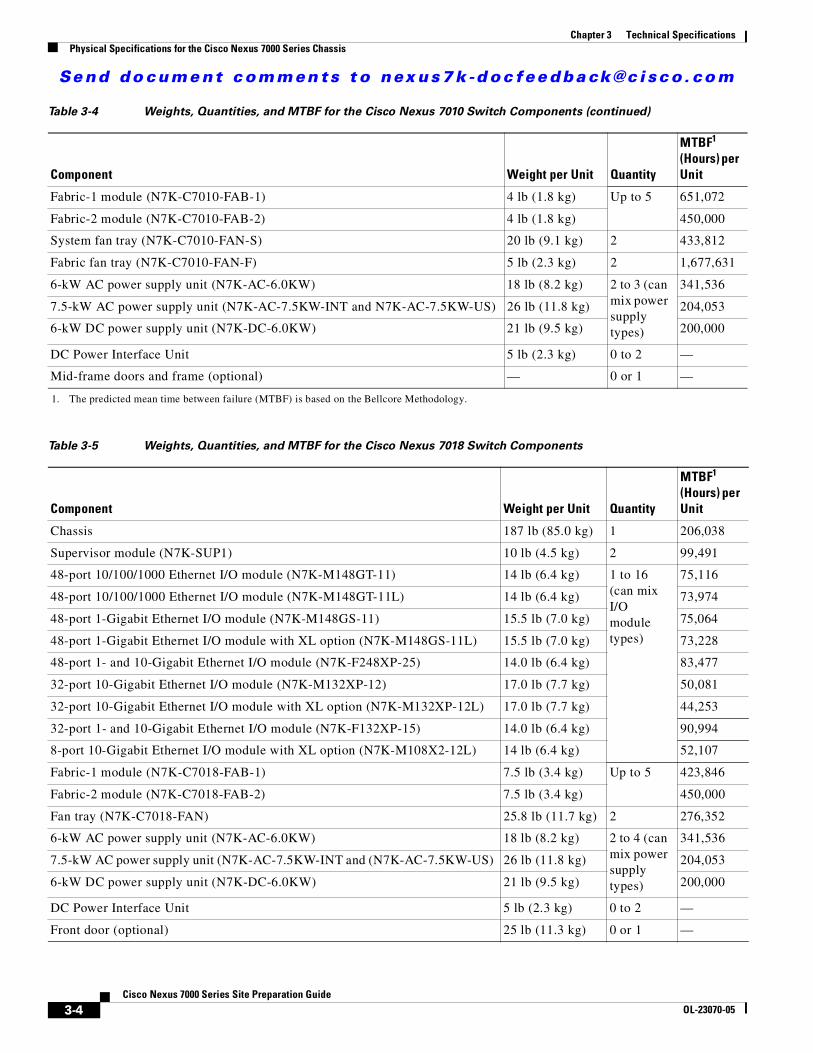
The weights, quantities, and mean time between failures (MTBF) hours are listed in Table 3-3 for the Cisco Nexus 7009 switch, Table 3-4 for the Cisco Nexus 7010 switch, and Table 3-5 for the Cisco Nexus 7018 switch. The weights in these tables do not include the rack or cabinet that holds the chassis or the interface and power cables. For those weights, see the documentation provided by the manufacturers of those components.
Noise Sound pressure levels
Without air filter 63.6 dBA 67.2 dBA 65.0 dBA
With air filter — 70.2 dBA —
Sound power levels
Without air filter 72.5 dBA 78.9 dBA 74.2 dBA
With air filter — 81.7 dBA —
Table 3-1 Environmental Specifications for the Cisco Nexus 7000 Series Switches (continued)
Description Cisco Nexus 7009 Cisco Nexus 7010 Cisco Nexus 7018
Table 3-2 Dimensions for the Cisco Nexus 7000 Series Chassis
Chassis Width Depth1
1. This measurement is from the mounting bracket to the rear of the chassis (including the module handles at the rear). For the cable management system on either chassis, add 6.0 inches (15.4 cm) in front of the mounting brackets. The six inches in front of the mounting brackets includes the optional air filter and the optional front door and frame assemblies on the Cisco Nexus 7010 chassis and it includes the optional front door and air intake frame on the Cisco Nexus 7009 and 7018 chassis.
Height2
2. The height includes the bottom-support bracket for the Cisco Nexus 7010 and 7018. For the Cisco Nexus 7009, you must add 0.75 inches (1.9 cm) for the bottom-support bracket, which can be removed after installation for front-mounted installations.
Cisco Nexus 7009 17.3 inches (43.9 cm) 24.0 inches (61.0 cm) 24.5 inches (62.2 cm) (14 RU)
Cisco Nexus 7010 17.3 inches (43.9 cm) 32.0 inches (81.3 cm) 36.75 inches (93.3 cm) (21.0 RU)
Cisco Nexus 7018 17.3 inches (43.9 cm) 32.0 inches (81.3 cm) 43.75 inches (111.1 cm) (25.0 RU)
Table 3-3 Weights, Quantities, and MTBF for the Cisco Nexus 7009 Switch Components
Component Weight per Unit Quantity
MTBF1 (Hours) per Unit
Chassis 100 lb (45.0 kg) 1 260,000
Supervisor module (N7K-SUP1) 10 lb (4.5 kg) 2 99,491

Se nd do cume nt c ommen ts t o nex us7k -d oc fee dba ck@c i sc o . co m
3-3Cisco Nexus 7000 Series Site Preparation Guide
OL-23070-05
Chapter 3 Technical SpecificationsPhysical Specifications for the Cisco Nexus 7000 Series Chassis
48-port 10/100/1000 Ethernet I/O module (N7K-M148GT-11) 14 lb (6.4 kg) 1 to 7 (can mix I/O module types)
75,116
48-port 10/100/1000 Ethernet I/O module (N7K-M148GT-11L) 14 lb (6.4 kg) 73,974
48-port 1-Gigabit Ethernet I/O module (N7K-M148GS-11) 15.5 lb (7.0 kg) 75,064
48-port 1-Gigabit Ethernet I/O module with XL option (N7K-M148GS-11L) 15.5 lb (7.0 kg) 73,228
48-port 1- and 10-Gigabit Ethernet I/O module (N7K-F248XP-25) 14.0 lb (6.4 kg) 83,477
32-port 10-Gigabit Ethernet I/O module (N7K-M132XP-12) 17.0 lb (7.7 kg) 50,081
32-port 10-Gigabit Ethernet I/O module with XL option (N7K-M132XP-12L) 17.0 lb (7.7 kg) 44,253
32-port 1- and 10-Gigabit Ethernet I/O module (N7K-F132XP-15) 14.0 lb (6.4 kg) 90,994
8-port 10-Gigabit Ethernet I/O module with XL option (N7K-M108X2-12L) 14.0 lb (6.4 kg) 52,107
Fabric-2 module (N7K-C7009-FAB-2) 5 lb (2.27 kg) 3 to 5 600,000
Fan tray (N7K-C7009-FAN) 25.0 lb (11.3 kg) 1 433,812
6-kW AC power supply unit (N7K-AC-6.0KW) 18 lb (8.2 kg) 1 or 2 (can mix power supply types)
341,536
7.5-kW AC power supply unit (N7K-AC-7.5KW-INT and N7K-AC-7.5KW-US) 26 lb (11.8 kg) 204,053
6-kW DC power supply unit (N7K-DC-6.0KW) 21 lb (9.5 kg) 200,000
DC Power Interface Unit 5 lb (2.3 kg) 0 to 2 —
Door and air frame (optional) — 0 or 1 —
1. The predicted mean time between failure (MTBF) is based on the Bellcore Methodology.
Table 3-3 Weights, Quantities, and MTBF for the Cisco Nexus 7009 Switch Components (continued)
Component Weight per Unit Quantity
MTBF1 (Hours) per Unit
Table 3-4 Weights, Quantities, and MTBF for the Cisco Nexus 7010 Switch Components
Component Weight per Unit Quantity
MTBF1 (Hours) per Unit
Chassis 200 lb (90.9 kg) 1 264,649
Supervisor module (N7K-SUP1) 10 lb (4.5 kg) 2 99,491
48-port 10/100/1000 Ethernet I/O module (N7K-M148GT-11) 14 lb (6.4 kg) 1 to 8 (can mix I/O module types)
75,116
48-port 10/100/1000 Ethernet I/O module (N7K-M148GT-11L) 14 lb (6.4 kg) 73,974
48-port 1-Gigabit Ethernet I/O module (N7K-M148GS-11) 15.5 lb (7.0 kg) 75,064
48-port 1-Gigabit Ethernet I/O module with XL option (N7K-M148GS-11L) 15.5 lb (7.0 kg) 73,228
48-port 1- and 10-Gigabit Ethernet I/O module (N7K-F248XP-25) 14.0 lb (6.4 kg) 83,477
32-port 10-Gigabit Ethernet I/O module (N7K-M132XP-12) 17.0 lb (7.7 kg) 50,081
32-port 10-Gigabit Ethernet I/O module with XL option (N7K-M132XP-12L) 17.0 lb (7.7 kg) 44,253
32-port 1- and 10-Gigabit Ethernet I/O module (N7K-F132XP-15) 14.0 lb (6.4 kg) 90,994
8-port 10-Gigabit Ethernet I/O module with XL option (N7K-M108X2-12L) 14.0 lb (6.4 kg) 52,107
Se nd do cume nt c ommen ts t o nex us7k -d oc fee dba ck@c i sc o . co m
3-4Cisco Nexus 7000 Series Site Preparation Guide
OL-23070-05
Chapter 3 Technical SpecificationsPhysical Specifications for the Cisco Nexus 7000 Series Chassis
Fabric-1 module (N7K-C7010-FAB-1) 4 lb (1.8 kg) Up to 5 651,072
Fabric-2 module (N7K-C7010-FAB-2) 4 lb (1.8 kg) 450,000
System fan tray (N7K-C7010-FAN-S) 20 lb (9.1 kg) 2 433,812
Fabric fan tray (N7K-C7010-FAN-F) 5 lb (2.3 kg) 2 1,677,631
6-kW AC power supply unit (N7K-AC-6.0KW) 18 lb (8.2 kg) 2 to 3 (can mix power supply types)
341,536
7.5-kW AC power supply unit (N7K-AC-7.5KW-INT and N7K-AC-7.5KW-US) 26 lb (11.8 kg) 204,053
6-kW DC power supply unit (N7K-DC-6.0KW) 21 lb (9.5 kg) 200,000
DC Power Interface Unit 5 lb (2.3 kg) 0 to 2 —
Mid-frame doors and frame (optional) — 0 or 1 —
1. The predicted mean time between failure (MTBF) is based on the Bellcore Methodology.
Table 3-5 Weights, Quantities, and MTBF for the Cisco Nexus 7018 Switch Components
Component Weight per Unit Quantity
MTBF1 (Hours) per Unit
Chassis 187 lb (85.0 kg) 1 206,038
Supervisor module (N7K-SUP1) 10 lb (4.5 kg) 2 99,491
48-port 10/100/1000 Ethernet I/O module (N7K-M148GT-11) 14 lb (6.4 kg) 1 to 16 (can mix I/O module types)
75,116
48-port 10/100/1000 Ethernet I/O module (N7K-M148GT-11L) 14 lb (6.4 kg) 73,974
48-port 1-Gigabit Ethernet I/O module (N7K-M148GS-11) 15.5 lb (7.0 kg) 75,064
48-port 1-Gigabit Ethernet I/O module with XL option (N7K-M148GS-11L) 15.5 lb (7.0 kg) 73,228
48-port 1- and 10-Gigabit Ethernet I/O module (N7K-F248XP-25) 14.0 lb (6.4 kg) 83,477
32-port 10-Gigabit Ethernet I/O module (N7K-M132XP-12) 17.0 lb (7.7 kg) 50,081
32-port 10-Gigabit Ethernet I/O module with XL option (N7K-M132XP-12L) 17.0 lb (7.7 kg) 44,253
32-port 1- and 10-Gigabit Ethernet I/O module (N7K-F132XP-15) 14.0 lb (6.4 kg) 90,994
8-port 10-Gigabit Ethernet I/O module with XL option (N7K-M108X2-12L) 14 lb (6.4 kg) 52,107
Fabric-1 module (N7K-C7018-FAB-1) 7.5 lb (3.4 kg) Up to 5 423,846
Fabric-2 module (N7K-C7018-FAB-2) 7.5 lb (3.4 kg) 450,000
Fan tray (N7K-C7018-FAN) 25.8 lb (11.7 kg) 2 276,352
6-kW AC power supply unit (N7K-AC-6.0KW) 18 lb (8.2 kg) 2 to 4 (can mix power supply types)
341,536
7.5-kW AC power supply unit (N7K-AC-7.5KW-INT and (N7K-AC-7.5KW-US) 26 lb (11.8 kg) 204,053
6-kW DC power supply unit (N7K-DC-6.0KW) 21 lb (9.5 kg) 200,000
DC Power Interface Unit 5 lb (2.3 kg) 0 to 2 —
Front door (optional) 25 lb (11.3 kg) 0 or 1 —
Table 3-4 Weights, Quantities, and MTBF for the Cisco Nexus 7010 Switch Components (continued)
Component Weight per Unit Quantity
MTBF1 (Hours) per Unit

Se nd do cume nt c ommen ts t o nex us7k -d oc fee dba ck@c i sc o . co m
3-5Cisco Nexus 7000 Series Site Preparation Guide
OL-23070-05
Chapter 3 Technical SpecificationsPower Specifications for Cisco Nexus 7000 Series Switches
Power Specifications for Cisco Nexus 7000 Series SwitchesThe number of power supplies that a Cisco Nexus 7000 Series switch requires depends on the quantities and types of modules that you include in the switch chassis, the type of power supply units that you are using, and the power redundancy mode that you are using.
The following topics explain how to calculate the switch power requirements and the amount of power available for each type of power supply configuration mode:
• Power Requirements for Switch Components, page 3-5
• Power Supply Configuration Modes, page 3-6
Power Requirements for Switch ComponentsTo determine the power requirements of the Cisco Nexus 7000 Series switches, add the power requirements of each of its components. For each component, multiply the number of its modules by its maximum or typical power requirement. To find the quantities and power requirements for each Cisco Nexus 7000 Series switch, see Table 3-6 for the Cisco Nexus 7009 switch, see Table 3-7 for the Cisco Nexus 7010 switch, and see Table 3-8 for the Cisco Nexus 7018 switch.
1. The predicted mean time between failure (MTBF) is based on the Bellcore Methodology.
Table 3-6 Power Requirements for the Cisco Nexus 7009 Switch
Component Quantity Maximum Typical
Supervisor module 2 210 W 190 W
48-port 10/100/1000 Ethernet I/O module 1 to 7 400 W 358 W
48-port 10/100/1000 Ethernet I/O module with XL option 400 W 358 W
48-port 1-Gigabit Ethernet I/O module 400 W 358 W
48-port 1-Gigabit Ethernet I/O module with XL option 400 W 358 W
48-port 1- and 10-Gigabit Ethernet I/O module 450 W 400 W
32-port 10-Gigabit Ethernet I/O module 750 W 611 W
32-port 10-Gigabit Ethernet I/O module with XL option 750 W 611 W
32-port 1- and 10-Gigabit Ethernet I/O module 385 W 283 W
8-port 10-Gigabit Ethernet I/O module with XL option 650 W 520 W
Fabric-2 module 3 to 5 70 W 55 W
All fan trays (total) — 650 W 190 W
Table 3-7 Power Requirements for the Cisco Nexus 7010 Switch
Component Quantity Maximum Typical
Supervisor module 2 210 W 190 W

Se nd do cume nt c ommen ts t o nex us7k -d oc fee dba ck@c i sc o . co m
3-6Cisco Nexus 7000 Series Site Preparation Guide
OL-23070-05
Chapter 3 Technical SpecificationsPower Specifications for Cisco Nexus 7000 Series Switches
Power Supply Configuration ModesYou can configure one of the following power modes to either use the combined power provided by the
installed power supply units or to provide power redundancy when there is a power loss:
• Combined mode—Provides the maximum amount of available power by utilizing the combined
power output from all installed power supply units for switch operations. This mode does not
provide redundancy.
48-port 10/100/1000 Ethernet I/O module 1 to 8 400 W 358 W
48-port 10/100/1000 Ethernet I/O module with XL option 400 W 358 W
48-port 1-Gigabit Ethernet I/O module 400 W 358 W
48-port 1-Gigabit Ethernet I/O module with XL option 400 W 358 W
48-port 1- and 10-Gigabit Ethernet I/O module 450 W 400 W
32-port 10-Gigabit Ethernet I/O module 750 W 611 W
32-port 10-Gigabit Ethernet I/O module with XL option 750 W 611 W
32-port 1- and 10-Gigabit Ethernet I/O module 385 W 283 W
8-port 10-Gigabit Ethernet I/O module with XL option 650 W 520 W
Fabric-1 module 3 to 5 60 W 55 W
Fabric-2 module 80 W 60W
All fan trays (total) — 2184 W 300 W
Table 3-8 Power Requirements for the Cisco Nexus 7018 Switch
Component Quantity Maximum Typical
Supervisor module 2 210 W 190 W
48-port 10/100/1000 Ethernet I/O module 1 to 16 400 W 358 W
48-port 10/100/1000 Ethernet I/O module with XL option 400 W 358 W
48-port 1-Gigabit Ethernet I/O module 400 W 358 W
48-port 1-Gigabit Ethernet I/O module with XL option 400 W 358 W
48-port 1- and 10-Gigabit Ethernet I/O module 450 W 400 W
32-port 10-Gigabit Ethernet I/O module 750 W 611 W
32-port 10-Gigabit Ethernet I/O module with XL option 750 W 611 W
32-port 1- and 10-Gigabit Ethernet I/O module 385 W 283 W
8-port 10-Gigabit Ethernet I/O module with XL option 650 W 520 W
Fabric-1 module 3 to 5 100 W 90 W
Fabric-2 module 150 W 110 W
All fan trays (total) — 1433 W 569 W
Table 3-7 Power Requirements for the Cisco Nexus 7010 Switch (continued)
Component Quantity Maximum Typical

Se nd do cume nt c ommen ts t o nex us7k -d oc fee dba ck@c i sc o . co m
3-7Cisco Nexus 7000 Series Site Preparation Guide
OL-23070-05
Chapter 3 Technical SpecificationsPower Specifications for Cisco Nexus 7000 Series Switches
• Power-supply redundancy mode—Allows you to replace a power supply during switch operations.
All power supplies are active. The available power is calculated as the least amount of power
available from all but one of the power supply units (N+1). The reserve power is the amount of
power output by the power supply unit that can output the most power. For example, if three power
supply units output 3 kW, 6 kW, and 6 kW, the available power is 9 kW (3 kW + 6 kW) and the
reserve power is 6 kW.
• Input source redundancy mode—Takes power from two electrical grids so that if one grid goes
down, the other grid can provide the power needed by the switch. Each grid powers half of each
power supply unit (grid A is connected to the Input 1 receptacle on each power supply unit and grid
B is connected to the Input 2 receptacle on each power supply unit). The available power is the
amount of power output by the portions of the power supply units that are connected to the same
grid. For example, if three power supply units are connected to a 110-V grid and a 220-V grid, each
power supply outputs 1.2 kW for the 110-V grid and 3.0 kW for the 220-V grid. The available power
would be 3.6 kW (1.2 kW + 1.2 kW + 1.2 kW) and the reserve power would be 9.0 kW (3.0 kW +
3.0 kW + 3.0 kW).
• Full redundancy mode—Provides both power-supply redundancy and input-source redundancy.
This mode allows you to replace a power supply unit without interrupting switch operations or
continue powering the switch if one of two grids goes down. The available power is the lesser
amount of output power for power supply redundancy or input source redundancy.
The amount of power available for use with your Cisco Nexus 7000 Series switch depends on the number of power supply units, input voltage used, and the power mode used. To determine the amount of available power for 6-kW AC power supply units, see Table 3-9. To determine the amount of power available for 7.5-kW AC power supply units, see Table 3-10. To determine the amount of power available for the 6-kW DC power supply units, see Table 3-11.
Table 3-9 Power Availability for 6-kW AC Power Supply Units
Power InputsCombined Mode
Power Supply Redundancy Mode
Input Source Redundancy Mode
Full Redundancy Mode
Dual inputs per power supply unit
220-V and 220-V inputs
1 power supply unit 6000 W — 3000 W —
2 power supply units 12,000 W 6000 W 6000 W 6000 W
3 power supply units 18,000 W 12,000 W 9000 W 9000 W
4 power supply units1 24,000 W 18,000 W 12,000 W 12,000 W
220-V and 110-V inputs
1 power supply unit 4200 W — 1200 W —
2 power supply units 8400 W 4200 W 2400 W 2400 W
3 power supply units 12,600 W 8400 W 3600 W 3600 W
4 power supply units1 16,800 W 12,600 W 4800 S 4800 W
110-V and 110-V inputs
1 power supply unit 2400 W — 1200 W —
2 power supply units 4800 W 2400 W 2400 W 2400 W
3 power supply units 7200 W 4800 W 3600 W 3600 W

Se nd do cume nt c ommen ts t o nex us7k -d oc fee dba ck@c i sc o . co m
3-8Cisco Nexus 7000 Series Site Preparation Guide
OL-23070-05
Chapter 3 Technical SpecificationsPower Specifications for Cisco Nexus 7000 Series Switches
4 power supply units1 9600 W 7200 W 4800 W 4800 W
Single input per power supply unit
220-V input
1 power supply unit 3000 W — — —
2 power supply units 6000 W 3000 W — —
3 power supply units 9000 W 6000 W — —
4 power supply units1 12,000 W 9000 W — —
110-V input
1 power supply unit 1200 W — — —
2 power supply units 2400 W 1200 W — —
3 power supply units 3600 W 2400 W — —
4 power supply units1 4800 W 3600 W — —
1. A fourth power supply unit can be added to only the Cisco Nexus 7018 switch. The Cisco Nexus 7010 holds up to three power supply units.
Table 3-9 Power Availability for 6-kW AC Power Supply Units (continued)
Power InputsCombined Mode
Power Supply Redundancy Mode
Input Source Redundancy Mode
Full Redundancy Mode
Table 3-10 Power Availability for 7.5-kW AC Power Supply Units
Power InputsCombinedMode
Power SupplyRedundancyMode
Input SourceRedundancyMode
FullRedundancyMode
Dual inputs per power supply unit
220-V and 220-V inputs
1 power supply unit 7500 W — 3750 W —
2 power supply units 15,000 W 7500 W 7500 W 7500 W
3 power supply units 22,500 W 15,000 W 11,250 W 11,250 W
4 power supply units1 30,000 W 22,500 W 15,000 W 15,000 W
Single input per power supply unit
220-V input
1 power supply unit 3750 W — — —
2 power supply units 7500 W 3750 W — —
3 power supply units 11,250 W 7500 W — —
4 power supply units1 15,000 W 11,250 W — —
1. A fourth power supply unit can be added to only the Cisco Nexus 7018 switch. The Cisco Nexus 7010 holds up to three power supply units.
Se nd do cume nt c ommen ts t o nex us7k -d oc fee dba ck@c i sc o . co m
3-9Cisco Nexus 7000 Series Site Preparation Guide
OL-23070-05
Chapter 3 Technical SpecificationsPower Supply Cable Specifications
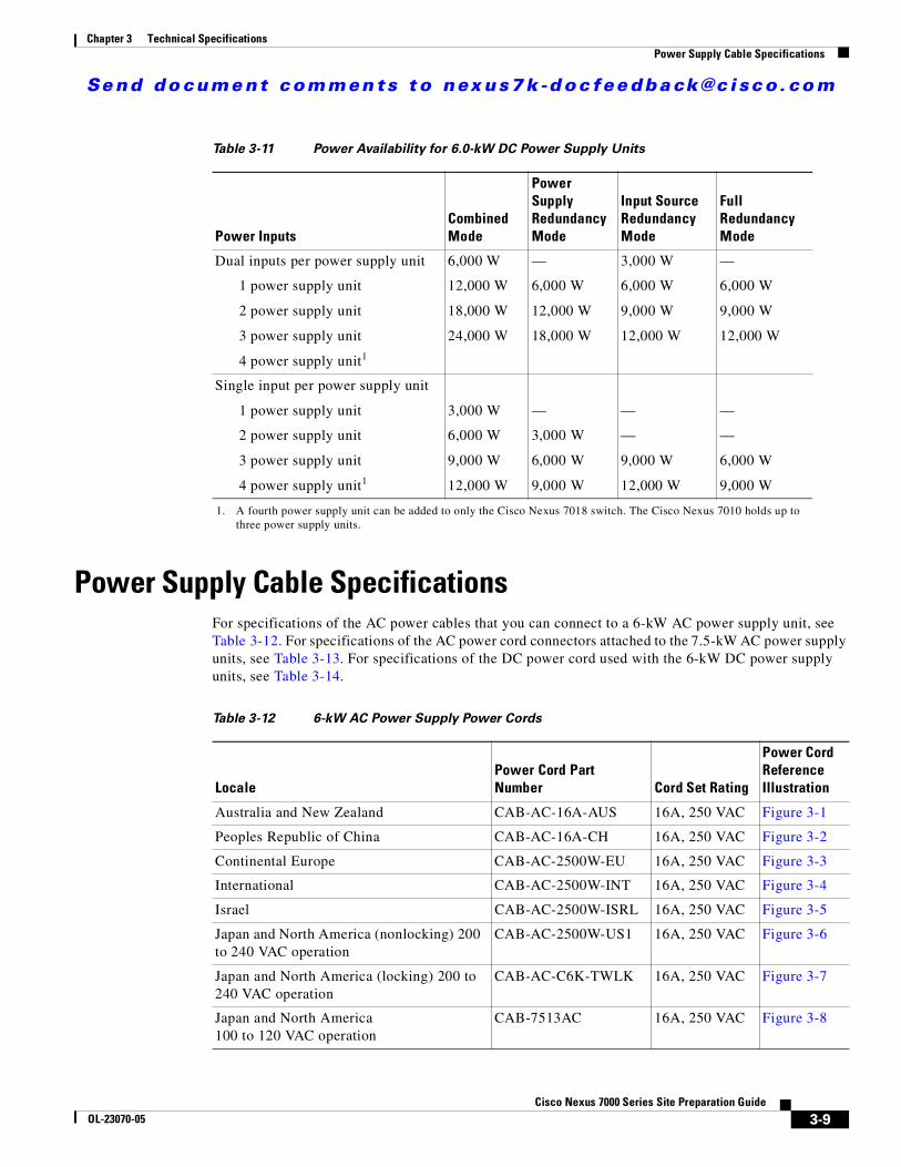
Power Supply Cable SpecificationsFor specifications of the AC power cables that you can connect to a 6-kW AC power supply unit, see Table 3-12. For specifications of the AC power cord connectors attached to the 7.5-kW AC power supply units, see Table 3-13. For specifications of the DC power cord used with the 6-kW DC power supply units, see Table 3-14.
Table 3-11 Power Availability for 6.0-kW DC Power Supply Units
Power InputsCombinedMode
Power SupplyRedundancyMode
Input SourceRedundancyMode
FullRedundancyMode
Dual inputs per power supply unit
1 power supply unit
2 power supply unit
3 power supply unit
4 power supply unit1
6,000 W
12,000 W
18,000 W
24,000 W
—
6,000 W
12,000 W
18,000 W
3,000 W
6,000 W
9,000 W
12,000 W
—
6,000 W
9,000 W
12,000 W
Single input per power supply unit
1 power supply unit
2 power supply unit
3 power supply unit
4 power supply unit1
3,000 W
6,000 W
9,000 W
12,000 W
—
3,000 W
6,000 W
9,000 W
—
—
9,000 W
12,000 W
—
—
6,000 W
9,000 W
1. A fourth power supply unit can be added to only the Cisco Nexus 7018 switch. The Cisco Nexus 7010 holds up to three power supply units.
Table 3-12 6-kW AC Power Supply Power Cords
LocalePower Cord Part Number Cord Set Rating
Power Cord Reference Illustration
Australia and New Zealand CAB-AC-16A-AUS 16A, 250 VAC Figure 3-1
Peoples Republic of China CAB-AC-16A-CH 16A, 250 VAC Figure 3-2
Continental Europe CAB-AC-2500W-EU 16A, 250 VAC Figure 3-3
International CAB-AC-2500W-INT 16A, 250 VAC Figure 3-4
Israel CAB-AC-2500W-ISRL 16A, 250 VAC Figure 3-5
Japan and North America (nonlocking) 200 to 240 VAC operation
CAB-AC-2500W-US1 16A, 250 VAC Figure 3-6
Japan and North America (locking) 200 to 240 VAC operation
CAB-AC-C6K-TWLK 16A, 250 VAC Figure 3-7
Japan and North America 100 to 120 VAC operation
CAB-7513AC 16A, 250 VAC Figure 3-8

Se nd do cume nt c ommen ts t o nex us7k -d oc fee dba ck@c i sc o . co m
3-10Cisco Nexus 7000 Series Site Preparation Guide
OL-23070-05
Chapter 3 Technical SpecificationsPower Supply Cable Specifications
Figure 3-1 CAB-AC-16A-AUS Power Cord and Connectors for the 6-kW Power Supply
Figure 3-2 CAB-AC-16A-CH Power Cord and Connectors for the 6-kW Power Supply
North America125 VAC operation
CAB-L520P 16A, 250 VAC Figure 3-9
Power distribution unit (PDU) CAB-C19-CBN 16A, 250 VAC Figure 3-10
Switzerland CAB-ACS-16 16A, 250 VAC Figure 3-11
Table 3-12 6-kW AC Power Supply Power Cords (continued)
LocalePower Cord Part Number Cord Set Rating
Power Cord Reference Illustration
Cordset rating: 16 A, 250 VLength: 14 ft 0 in. (4.26 m)
1405
86
Connector: IEC 60320 C19
Plug: AU20S3
1267
92
Cordset rating: 16A, 250VLength: 14 ft 0 in. (4.26 m)
Plug: GB16C Connector: IEC60320-1 C19
Se nd do cume nt c ommen ts t o nex us7k -d oc fee dba ck@c i sc o . co m
3-11Cisco Nexus 7000 Series Site Preparation Guide
OL-23070-05
Chapter 3 Technical SpecificationsPower Supply Cable Specifications
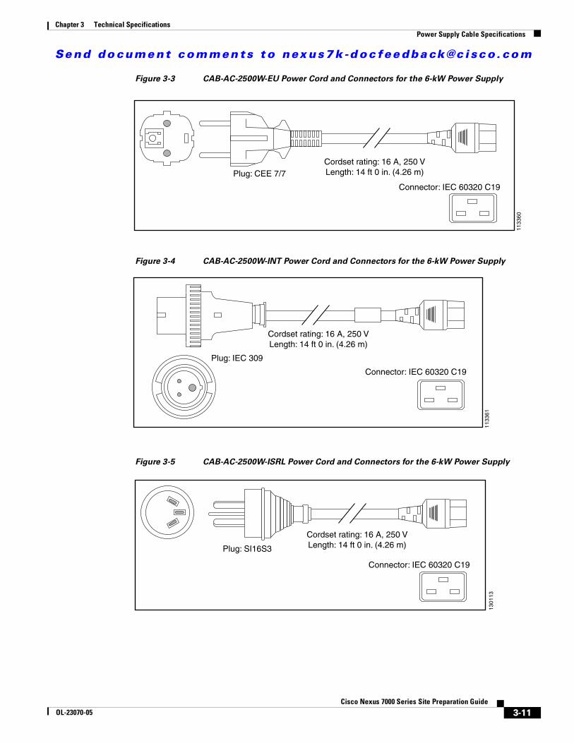
Figure 3-3 CAB-AC-2500W-EU Power Cord and Connectors for the 6-kW Power Supply
Figure 3-4 CAB-AC-2500W-INT Power Cord and Connectors for the 6-kW Power Supply
Figure 3-5 CAB-AC-2500W-ISRL Power Cord and Connectors for the 6-kW Power Supply
Cordset rating: 16 A, 250 VLength: 14 ft 0 in. (4.26 m)
1133
60
Connector: IEC 60320 C19
Plug: CEE 7/7
Cordset rating: 16 A, 250 VLength: 14 ft 0 in. (4.26 m)
1133
61
Connector: IEC 60320 C19
Plug: IEC 309
Plug: SI16S3
Cordset rating: 16 A, 250 VLength: 14 ft 0 in. (4.26 m)
1301
13
Connector: IEC 60320 C19

Se nd do cume nt c ommen ts t o nex us7k -d oc fee dba ck@c i sc o . co m
3-12Cisco Nexus 7000 Series Site Preparation Guide
OL-23070-05
Chapter 3 Technical SpecificationsPower Supply Cable Specifications
Figure 3-6 CAB-AC-2500W-US1 Power Cord and Connectors for the 6-kW Power Supply
Figure 3-7 CAB-AC-C6K-TWLK Power Cord and Connectors for the 6-kW Power Supply
Figure 3-8 CAB-7513AC Power Cord and Connectors for the 6-kW Power Supply
Cordset rating: 16 A, 250 VLength: 14 ft 0 in. (4.26 m)
1133
62
Connector: IEC 60320 C19
Plug: NEMA 6-20
Cordset rating: 16 A, 250 VLength: 14 ft 0 in. (4.26 m)
1133
63
Connector: IEC 60320 C19Plug: NEMA L6-20
Se nd do cume nt c ommen ts t o nex us7k -d oc fee dba ck@c i sc o . co m
3-13Cisco Nexus 7000 Series Site Preparation Guide
OL-23070-05
Chapter 3 Technical SpecificationsPower Supply Cable Specifications
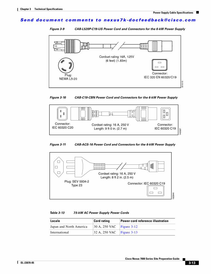
Figure 3-9 CAB-L520P-C19-US Power Cord and Connectors for the 6-kW Power Supply
Figure 3-10 CAB-C19-CBN Power Cord and Connectors for the 6-kW Power Supply
Figure 3-11 CAB-ACS-16 Power Cord and Connectors for the 6-kW Power Supply
Cordset rating: 16 A, 250 VLength: 9 ft 0 in. (2.7 m)
1405
87
Connector:IEC 60320 C19
Connector:IEC 60320 C20
Plug: SEV 5934-2
Type 23
Cordset rating: 16 A, 250 V
Length: 8 ft 2 in. (2.5 m)
19
28
44
Connector: IEC 60320 C19
Table 3-13 7.5-kW AC Power Supply Power Cords
Locale Cord rating Power cord reference illustration
Japan and North America 30 A, 250 VAC Figure 3-12
International 32 A, 250 VAC Figure 3-13

Se nd do cume nt c ommen ts t o nex us7k -d oc fee dba ck@c i sc o . co m
3-14Cisco Nexus 7000 Series Site Preparation Guide
OL-23070-05
Chapter 3 Technical SpecificationsPower Supply Cable Specifications
Figure 3-12 NEMA L6-30 Power Connector for the 7.5-kW Power Supply
Figure 3-13 IEC 603090 Power Connector for the 7.5-kW Power Supply
Cordset rating: 30 A, 250 VLength: 12 ft 0 in. (3.65 m)
Plug: NEMA L6-30
Hardwired to powersupply
1133
66
Cordset rating: 32 A, 250 VLength: 12 ft 0 in. (3.65 m)
Plug: IEC 60309
1133
65
Hardwired to powersupply
Table 3-14 6-kW DC Power Supply Power Cord
Locale Power Cord Part Number Cord Rating
All N7K-DC-CAB 40 A, 48V-48V

Se nd do cume nt c ommen ts t o nex us7k -d oc fee dba ck@c i sc o . co m
3-15Cisco Nexus 7000 Series Site Preparation Guide
OL-23070-05
Chapter 3 Technical SpecificationsChassis Clearances
Figure 3-14 Power Connector for the 6.0-kW DC Power Supply Unit
Chassis ClearancesYou must provide adequate clearance for installing the switch, replacing switch modules, routing cables, and allowing airflow to and from the switch.
This section includes the following topics:
• Cisco Nexus 7009 Chassis Clearances, page 3-15
• Cisco Nexus 7010 Chassis Clearances, page 3-16
• Cisco Nexus 7018 Chassis Clearances, page 3-16
Cisco Nexus 7009 Chassis ClearancesThe Cisco Nexus 7009 chassis requires the following clearances:
• If you are using a four-post rack or cabinet, you must have 7 inches (17.8 cm) between the chassis and the front and back of a four-post rack or interior of the cabinet (required for cabling). This requirement does not apply to a two-post rack.
Note If the chassis is installed with the alternative center-mount bottom-support brackets, the chassis will protrude 6 inches (15.25 cm) beyond the mounting rails, so you must plan for 13 inches (33.0 cm) clearance in front of the mounting rails to get the required 7 inches (17.8 cm) clearance in front of the chassis.
• 37 inches (94.0 cm) between the front of the chassis and the next rack, cabinet, or wall in the cold aisle (required for installing or replacing the chassis or its modules)

Se nd do cume nt c ommen ts t o nex us7k -d oc fee dba ck@c i sc o . co m
3-16Cisco Nexus 7000 Series Site Preparation Guide
OL-23070-05
Chapter 3 Technical SpecificationsFacility Cooling Requirements
• 26 inches (66.0 cm) between the rear of the chassis and the next rack, cabinet, or wall in the hot aisle (required for replacing the fan tray)
• 11 inches (27.9 cm) between the side of the chassis and the interior of the cabinet, or the clearance area for the next rack or cabinet (required for side-to-side airflow)
Cisco Nexus 7010 Chassis ClearancesThe Cisco Nexus 7010 chassis requires the following clearances:
• 7 inches (17.8 cm) between the chassis and the front and back of the rack or interior of the cabinet (required for cabling)
• 38 inches (96.5 cm) open passageway between the front of the rack or cabinet and the next rack, cabinet, or wall in the cold aisle (required for installing or replacing the chassis or its modules)
• 30 inches (76.2 cm) between the rear of the rack or cabinet and the next rack, cabinet, or wall in the hot aisle (required for replacing the fan tray)
Cisco Nexus 7018 Chassis ClearancesThe Cisco Nexus 7018 chassis requires the following clearances:
• 7 inches (17.8 cm) between the chassis and the front and back of the rack or interior of the cabinet (required for cabling)
• 38 inches (96.5 cm) open passageway between the front of the rack or cabinet and the next rack, cabinet, or wall in the cold aisle (required for installing or replacing the chassis or its modules)
• 30 inches (76.2 cm) between the rear of the rack or cabinet and the next rack, cabinet, or wall in the hot aisle (required for replacing the fan tray)
• 11 inches (27.9 cm) between the side of the chassis and the interior of the cabinet, or the clearance area for the next rack or cabinet (required for side-to-side airflow)
Facility Cooling RequirementsThe Cisco Nexus 7000 Series switches dissipate considerable power that generates much heat. The following is the heat dissipation requirement for these switches:
• Cisco Nexus 7009 dissipates up to 28,101 BTUs per hour
• Cisco Nexus 7010 dissipates up to 35,162 BTUs per hour
• Cisco Nexus 7018 dissipates up to 51,195 BTUs per hour
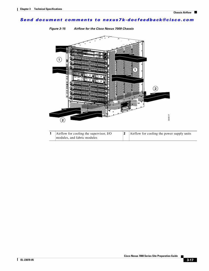
Chassis AirflowTo see how the cooling air flows through the Cisco Nexus 7000 Series switches, see Figure 3-15 for the Cisco Nexus 7009 switch, Figure 3-16 for the Cisco Nexus 7010 switch, and Figure 3-17 for the Cisco Nexus 7018 switch. All of the Cisco Nexus 7000 Series switches are designed to work in a hot-aisle/cold-aisle environment, but the Cisco Nexus 7009 and 7018 switches also require side clearances to allow airflow in and out the sides.
Se nd do cume nt c ommen ts t o nex us7k -d oc fee dba ck@c i sc o . co m
3-17Cisco Nexus 7000 Series Site Preparation Guide
OL-23070-05
Chapter 3 Technical SpecificationsChassis Airflow
Figure 3-15 Airflow for the Cisco Nexus 7009 Chassis
1 Airflow for cooling the supervisor, I/O modules, and fabric modules
2 Airflow for cooling the power supply units
Se nd do cume nt c ommen ts t o nex us7k -d oc fee dba ck@c i sc o . co m
3-18Cisco Nexus 7000 Series Site Preparation Guide
OL-23070-05
Chapter 3 Technical SpecificationsChassis Airflow
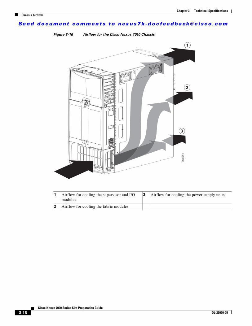
Figure 3-16 Airflow for the Cisco Nexus 7010 Chassis
270544
2
3
1
1 Airflow for cooling the supervisor and I/O modules
3 Airflow for cooling the power supply units
2 Airflow for cooling the fabric modules

Se nd do cume nt c ommen ts t o nex us7k -d oc fee dba ck@c i sc o . co m
3-19Cisco Nexus 7000 Series Site Preparation Guide
OL-23070-05
Chapter 3 Technical SpecificationsChassis Airflow
Figure 3-17 Airflow for the Cisco Nexus 7018 Chassis
To allow for the Cisco Nexus 7009 and 7018 switches to take in air from the cold aisle and floor on the right side, you should route cables on the left front side of the switch. If necessary, you can route cables on the upper right front side of the chassis, which leaves the lower right side open to cooling air from the cold aisle in front of the chassis. By having the cables on the left side and leaving the left rear side unobstructed, the exhaust is directed to the hot aisle in back.
For the clearances required on each side of the switch, see the “Chassis Clearances” section on page 3-15.
To determine the clearances required on each side of the switch, see the “Chassis Clearances” section on page 3-15.
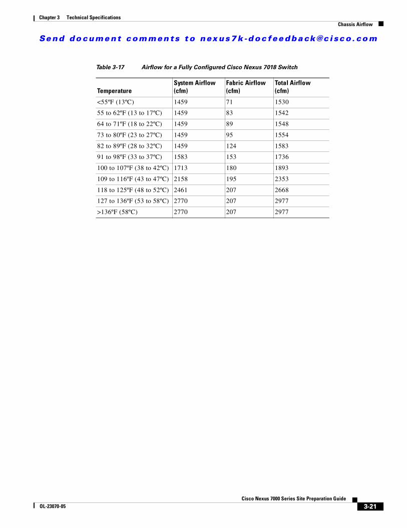
To determine the maximum amount of airflow for a fully configured switch, see Table 3-16 for the Cisco Nexus 7010 switch or see Table 3-17 for the Cisco Nexus 7018 switch.
189973
1
1
2
2
3
3
1 Airflow for cooling the supervisor and I/O modules
3 Airflow for cooling the power supply units
2 Airflow for cooling the fabric modules

Se nd do cume nt c ommen ts t o nex us7k -d oc fee dba ck@c i sc o . co m
3-20Cisco Nexus 7000 Series Site Preparation Guide
OL-23070-05
Chapter 3 Technical SpecificationsChassis Airflow
Note Systems with fewer than the maximum number of supervisor, I/O, or fabric modules will have less airflow.
Table 3-15 Airflow for a Fully Configured Cisco Nexus 7009 Switch
TemperatureSystem Airflow (cfm)
Fabric Airflow (cfm)
Total Airflow (cfm)
<55ºF (13ºC) 686 76 762
55 to 62ºF (13 to 17ºC) 686 92 778
64 to 71ºF (18 to 22ºC) 686 107 793
73 to 80ºF (23 to 27ºC) 686 123 809
82 to 89ºF (28 to 32ºC) 686 143 829
91 to 98ºF (33 to 37ºC) 768 153 921
100 to 107ºF (38 to 42ºC) 842 173 1015
109 to 116ºF (43 to 47ºC) 1044 189 1233
118 to 125ºF (48 to 52ºC) 1203 203 1406
127 to 136ºF (53 to 58ºC) 1326 221 1547
>136ºF (>58ºC) 1203 250 1576
Table 3-16 Airflow for a Fully Configured Cisco Nexus 7010 Switch
TemperatureSystem Airflow (cfm)
Fabric Airflow (cfm)
Total Airflow (cfm)
<55ºF (13ºC) 406 37 443
55 to 62ºF (13 to 17ºC) 493 44 537
64 to 71ºF (18 to 22ºC) 534 50 584
73 to 80ºF (23 to 27ºC) 576 56 632
82 to 89ºF (28 to 32ºC) 659 63 722
91 to 98ºF (33 to 37ºC) 744 70 814
100 to 107ºF (38 to 42ºC) 853 75 928
109 to 116ºF (43 to 47ºC) 1044 100 1144
118 to 125ºF (48 to 52ºC) 1242 154 1396
127 to 136ºF (53 to 58ºC) 1447 162 1609
>136ºF (>58ºC) 1447 162 1609
Se nd do cume nt c ommen ts t o nex us7k -d oc fee dba ck@c i sc o . co m
3-21Cisco Nexus 7000 Series Site Preparation Guide
OL-23070-05
Chapter 3 Technical SpecificationsChassis Airflow
Table 3-17 Airflow for a Fully Configured Cisco Nexus 7018 Switch
TemperatureSystem Airflow (cfm)
Fabric Airflow (cfm)
Total Airflow (cfm)
<55ºF (13ºC) 1459 71 1530
55 to 62ºF (13 to 17ºC) 1459 83 1542
64 to 71ºF (18 to 22ºC) 1459 89 1548
73 to 80ºF (23 to 27ºC) 1459 95 1554
82 to 89ºF (28 to 32ºC) 1459 124 1583
91 to 98ºF (33 to 37ºC) 1583 153 1736
100 to 107ºF (38 to 42ºC) 1713 180 1893
109 to 116ºF (43 to 47ºC) 2158 195 2353
118 to 125ºF (48 to 52ºC) 2461 207 2668
127 to 136ºF (53 to 58ºC) 2770 207 2977
>136ºF (58ºC) 2770 207 2977

Se nd do cume nt c ommen ts t o nex us7k -d oc fee dba ck@c i sc o . co m
3-22Cisco Nexus 7000 Series Site Preparation Guide
OL-23070-05
Chapter 3 Technical SpecificationsChassis Airflow

Se nd do cume nt c ommen ts t o nex us7k -d oc fee dba ck@c i sc o . co m
A-1Cisco Nexus 7000 Series Site Preparation Guide
OL-23070-05
A P P E N D I X ASite Preparation and Maintenance Records
This appendix provides a site planning list that you can use when preparing your site for the Cisco Nexus 7000 Series switches and includes these sections:
• Site Preparation Checklist, page A-1
• Contact and Site Information, page A-3
• Chassis and Module Information, page A-3
Site Preparation ChecklistPlanning the location and layout of your equipment rack or cabinet is essential for successful switch operation, ventilation, and accessibility.
Table A-1 lists the site planning tasks that we recommend that you complete before you install the Cisco Nexus 7000 Series switches. Your completion of each task ensures a successful switch installation.
Table A-1 Site Preparation Checklist
Planning Activity Verification Time and Date
Space evaluation:
• Space and layout
• Floor covering
• Impact and vibration
• Lighting
• Physical access
• Maintenance access
Environmental evaluation:
• Ambient temperature
• Humidity
• Altitude
• Atmospheric contamination
• Airflow

Se nd do cume nt c ommen ts t o nex us7k -d oc fee dba ck@c i sc o . co m
A-2Cisco Nexus 7000 Series Site Preparation Guide
OL-23070-05
Appendix A Site Preparation and Maintenance RecordsSite Preparation Checklist
Power evaluation:
• Input power type
• Power receptacles
• Receptacle proximity to the equipment
• Dedicated (separate) circuits for power redundancy
• UPS for power failures
• Grounding: proper gauge wire and lugs
• Circuit breaker size
Grounding evaluation:
• Data center ground
Cable and interface equipment evaluation:
• Cable type
• Connector type
• Cable distance limitations
• Interface equipment (transceivers)
EMI evaluation:
• Distance limitations for signaling
• Site wiring
• RFI levels
Table A-1 Site Preparation Checklist (continued)
Planning Activity Verification Time and Date

Se nd do cume nt c ommen ts t o nex us7k -d oc fee dba ck@c i sc o . co m
A-3Cisco Nexus 7000 Series Site Preparation Guide
OL-23070-05
Appendix A Site Preparation and Maintenance RecordsContact and Site Information
Contact and Site InformationUse the following worksheet (Table A-2) to record contact and site information.
Chassis and Module InformationUse the following worksheets (Table A-3, Table A-4, Table A-5, and Table A-6) to record information about the chassis and modules.
Contract Number
Chassis serial number
Product number
Table A-2 Contact and Site Information
Contact person
Contact phone
Contact e-mail
Building/site name
Data center location
Floor location
Address (line 1)
Address (line 2)
City
State
ZIP code
Country
Table A-3 Network-Related Information
Switch IP address
Switch IP netmask
Hostname
Domain name
IP broadcast address
Gateway/router address
DNS address

Se nd do cume nt c ommen ts t o nex us7k -d oc fee dba ck@c i sc o . co m
A-4Cisco Nexus 7000 Series Site Preparation Guide
OL-23070-05
Appendix A Site Preparation and Maintenance RecordsChassis and Module Information
Table A-4 Cisco Nexus 7009 Module Information
Slot Module Type Module Serial Number Notes
1 Supervisor
2 Supervisor
3
4
5
6
7
8
9
Table A-5 Cisco Nexus 7010 Module Information
Slot Module Type Module Serial Number Notes
1
2
3
4
5 Supervisor
6 Supervisor
7
8
9
10
Table A-6 Cisco Nexus 7018 Module Information
Slot Module Type Module Serial Number Notes
1
2
3
4
5
6
7
8

Se nd do cume nt c ommen ts t o nex us7k -d oc fee dba ck@c i sc o . co m
A-5Cisco Nexus 7000 Series Site Preparation Guide
OL-23070-05
Appendix A Site Preparation and Maintenance RecordsChassis and Module Information
9 Supervisor
10 Supervisor
11
12
13
14
15
16
17
18
Table A-6 Cisco Nexus 7018 Module Information
Slot Module Type Module Serial Number Notes

Se nd do cume nt c ommen ts t o nex us7k -d oc fee dba ck@c i sc o . co m
A-6Cisco Nexus 7000 Series Site Preparation Guide
OL-23070-05
Appendix A Site Preparation and Maintenance RecordsChassis and Module Information

Se nd do cume nt c ommen ts t o nex us7k -d oc fee dba ck@c i sc o . co m
B-1Cisco Nexus 7000 Series Site Preparation Guide
OL-23070-05
A P P E N D I X BCabinet and Rack Requirements
This appendix describes the cabinet and rack requirements for the Cisco Nexus 7000 Series switches and includes these sections:
• General Requirements for Cabinets and Racks, page B-1
• Cabinet and Rack Vendors, page B-3
General Requirements for Cabinets and RacksThis section provides the Cisco Nexus 7000 Series switch requirements for the following types of racks and cabinets, assuming an external ambient air temperature range of 32 to 104°F (0 to 40°C):
• Standard perforated cabinets
• Solid-walled cabinets with a roof fan tray (bottom to top cooling)
• Standard open racks
• Four-post Telco racks (required by the Cisco Nexus 7010 and 7018 switches and can be used for the Cisco Nexus 7009 switches)
• Two-post Telco racks (used with only the Cisco Nexus 7009 switches)
Note If you select an enclosed cabinet, we recommend that you use one of the following thermally validated types: standard perforated or solid-walled with a fan tray.
To correctly install the Cisco Nexus 7000 Series switch in a cabinet that is located in a hot-aisle/cold-aisle environment, you should fit a cabinet with baffles to prevent exhaust air from recirculating into the chassis air intake.
The rack or cabinet used to hold a Cisco Nexus 7000 Series chassis should meet the following physical requirements:
• Use a standard 19-inch, four-post Electronic Industries Alliance (EIA) cabinet or rack with mounting rails that conform to English universal hole spacing per section 1 of the ANSI/EIA-310-D-1992 standard.
• The height of the rack or cabinet must accommodate the Cisco Nexus 7000 Series switches as follows:
– For the Cisco Nexus 7009 switch, the rack height must be at least 15 RU for one chassis and at least 30 RU for two chassis.

Se nd do cume nt c ommen ts t o nex us7k -d oc fee dba ck@c i sc o . co m
B-2Cisco Nexus 7000 Series Site Preparation Guide
OL-23070-05
Appendix B Cabinet and Rack RequirementsGeneral Requirements for Cabinets and Racks
Note Alternatively, if you need to install three 14 RU Cisco Nexus 7009 chassis in a 42 RU rack, you can perform a front-mount installation for all three chassis without using the bottom-support rails. For front-mount installations, you must use a mechanical lift to first position the lowest chassis at the lowest RU in the rack before attaching it. After that, you raise a second chassis to the top of the lowest chassis and slide the second chassis on top before attaching it to the rack. Finally, you raise a third chassis to the top of the second installed chassis, slide the third one on top of the second installed chassis before attaching it to the rack.
Caution If you are doing center-mount installations, you must use a bottom-support rail for each chassis, which requires 15 RU for each installed chassis.
– For the Cisco Nexus 7010 switch, the rack height must be at least 21 RU for one chassis and 42 RU for two chassis (45 RU is recommended).
– For the Cisco Nexus 7018 switch, the rack height must be at least 25 RU for one chassis.
• The depth of a four-post rack must be 24 to 32 inches (61.0 to 81.3 cm) between the front and rear mounting brackets.
• Required clearances between the Cisco Nexus 7009 chassis and the edge of its rack or interior of its cabinet are as follows:
– If you are using a four-post rack or cabinet, you must have 7 inches (17.8 cm) between the chassis and the front and back of a four-post rack or interior of the cabinet (required for cabling). This requirement does not apply to a two-post rack.
Note If the chassis is installed with the alternative center-mount bottom-support brackets, the chassis will protrude 6 inches (15.25 cm) beyond the mounting rails, so you must plan for 13 inches (33.0 cm) clearance in front of the mounting rails to get the required 7 inches (17.8 cm) clearance in front of the chassis.
– 11 inches (27.9 cm) between the side of the chassis and the interior of the cabinet or the clearance area for the next rack or cabinet (required for side-to-side airflow with all types of racks or cabinets)
• Required clearances between the Cisco Nexus 7010 chassis and the edges of its rack or the interior of its cabinet are as follows:
– 7 inches (17.8 cm) between the chassis and the front and back of the rack or interior of the cabinet (required for cabling)
– No clearance is required to the sides of the rack or cabinet with front-to-back airflow.
• Required clearances between the Cisco Nexus 7018 chassis and the edges of its rack or the interior of its cabinet are as follows:
– 7 inches (17.8 cm) between the chassis and the front and back of the rack or interior of the cabinet (required for cabling)
– 11 inches (27.9 cm) between the side of the chassis and the interior of the cabinet or the clearance area for the next rack or cabinet (required for side-to-side airflow)
Additionally, you must consider the following site requirements for the rack:
• AC power receptacles must be located within 12 feet (3.6 m) of each power supply unit in each chassis.
Se nd do cume nt c ommen ts t o nex us7k -d oc fee dba ck@c i sc o . co m
B-3Cisco Nexus 7000 Series Site Preparation Guide
OL-23070-05
Appendix B Cabinet and Rack RequirementsCabinet and Rack Vendors
• Cable management for one or two switches in the same rack are as follows:
– For the Cisco Nexus 7009 switch, provide cable management for up to 336 ports for each chassis.
– For the Cisco Nexus 7010 switch, provide cable management for up to 384 ports for each chassis.
– For the Cisco Nexus 7018 switch, provide cable management for up to 768 ports for each chassis.
• Cable routing within the cabinet or beside the rack must not block access to any of the removable modules installed in a chassis or block any airflow on the inlet and exhaust vents of the chassis. With cabinets, route the cables out the top or bottom as follows:
– For the Cisco Nexus 7009 switch, route the cables along the left side of the front of the chassis so that cooling air can flow to the chassis from the right front side and heated exhaust air is vented to the left and directed to the hot aisle in the rear. If necessary, you can also route cables to the upper half of the right side of the chassis if the lower right side of the front is open for airflow from the cold-aisle and floor to the air intake.
– For the Cisco Nexus 7010 switch, route the cables through the cable management area on the top front of the switch.
– For the Cisco Nexus 7018 switch, route the cables along the left side of the front of the chassis so that cooling air can flow to the chassis from the right front side and heated exhaust air is vented to the left and directed to the hot aisle in the rear. If necessary, you can also route cables to the upper half of the right side of the chassis if the lower right side of the front is open for airflow from the cold-aisle and floor to the air intake.
• Where necessary, have a seismic rating of Network Equipment Building Standards (NEBS) Zone 3 or Zone 4, per GR-63-CORE if required.
• Minimum gross load rating of 2000 lb (907.2 kg) (static load rating) if supporting two switches.
Cabinet and Rack VendorsYou can install a Cisco Nexus 7000 Series switch in any cabinet or rack that meets the specifications listed in the “General Requirements for Cabinets and Racks” section on page B-1. Work with your cabinet vendors to determine which of their cabinets meet these requirements or see the Cisco Technical Assistance Center (TAC) for recommendations.

Se nd do cume nt c ommen ts t o nex us7k -d oc fee dba ck@c i sc o . co m
B-4Cisco Nexus 7000 Series Site Preparation Guide
OL-23070-05
Appendix B Cabinet and Rack RequirementsCabinet and Rack Vendors

Se nd do cume nt c ommen ts t o nex us7k -d oc fee dba ck@c i sc o . co m
IN-1Nexus 7000 Series Site Preparation Guide
OL-23070-05
I N D E X
Numerics
32-port 10-Gigabit Ethernet I/O module
MTBF 3-3, 3-4
power requirements 3-5, 3-6
weight 3-3, 3-4
32-port 10-Gigabit Ethernet I/O module with XL
MTBF 3-3, 3-4
power requirements 3-5, 3-6
weight 3-3, 3-4
32-port 1- and 10-Gigabit Ethernet I/O module
MTBF 3-3, 3-4
power requirements 3-5, 3-6
weight 3-3, 3-4
48-port 10/100/1000 Ethernet I/O module
MTBF 3-3, 3-4
power requirements 3-5, 3-6
weight 3-3, 3-4
48-port 10/100/1000 Ethernet I/O module with XL
MTBF 3-3, 3-4
power requirements 3-5, 3-6
weight 3-3, 3-4
48-port 1- and 10-gigabit Ethernet I/O module
MTBF 3-3, 3-4
weight 3-3, 3-4
48-port 1- and 10-Gigabit Ethernet I/O module with XL
power requirements 3-5, 3-6
48-port 1-Gigabit Ethernet I/O module
MTBF 3-3, 3-4
power requirements 3-5, 3-6
weight 3-3, 3-4
48-port 1-Gigabit Ethernet I/O module with XL
MTBF 3-3, 3-4
power requirements 3-5, 3-6
weight 3-3, 3-4
6-kW AC power supply unit
cable specifications 3-9
MTBF 3-4
weight 3-3, 3-4
6-kW DC power supply unit
cable specifications 3-14
MTBF 3-4
weight 3-3, 3-4
7.5-kW AC power supply unit
cable specifications 3-9
MTBF 3-4
weight 3-3, 3-4
8-port 10-Gigabit Ethernet I/O module with XL
MTBF 3-3, 3-4
power requirements 3-5, 3-6
weight 3-3, 3-4
A
airflow
Cisco Nexus 7009 3-17
Cisco Nexus 7010 3-18
Cisco Nexus 7018 3-19
altitude
preparing for 2-3
specifications 3-1
C
cabinets
requirements B-1
Se nd do cume nt c ommen ts t o nex us7k -d oc fee dba ck@c i sc o . co m
Index
IN-2Nexus 7000 Series Site Preparation Guide
OL-23070-05
vendors B-3
cable management B-3
cable routing
Cisco Nexus 7009 chassis B-3
Cisco Nexus 7010 chassis B-3
Cisco Nexus 7018 chassis B-3
chassis
airflow 3-16
clearance inside rack
Cisco Nexus 7009 3-15
Cisco Nexus 7010 3-16, B-2
Cisco Nexus 7018 3-16, B-2
clearance outside rack
Cisco Nexus 7009 3-15
Cisco Nexus 7010 3-16
Cisco Nexus 7018 3-16
records A-3
weight
Cisco Nexus 7009 3-2
Cisco Nexus 7010 3-3
Cisco Nexus 7018 3-4
checklist, site preparation A-1
Cisco Nexus 7009
airflow 3-17
cable routing B-3
chassis dimensions 3-2
clearances 3-15
components 1-1
component weights 3-2
MTBF 3-2
power requirements 3-5
Cisco Nexus 7010
airflow 3-18
cable routing B-3
chassis dimensions 3-2
clearances 3-16
component power requirements 3-5, 3-6
components 1-1
component weights 3-3
MTBF 3-3
power requirements 3-5
Cisco Nexus 7018
airflow 3-19
cable routing B-3
chassis dimensions 3-2
clearances 3-16
component power requirements 3-6
components 1-1
component weights 3-4
MTBF 3-4
power requirements 3-6
clearances
Cisco Nexus 7009
inside the rack 3-15
outside the rack 3-15
Cisco Nexus 7010
inside the rack 3-16, B-2
outside the rack 3-16
Cisco Nexus 7018
inside the rack 3-16, B-2
outside the rack 3-16
planning 3-15
combined power mode 3-6
contact list A-3
cooling requirements 3-16
corrosion, preventing 2-3
D
DC Power Interface Unit
quantity 1-2, 3-4
weight 3-4
dust, minimizing 2-3
E
electromagnetic interference (EMI), preparing for 2-3
Se nd do cume nt c ommen ts t o nex us7k -d oc fee dba ck@c i sc o . co m
Index
IN-3Nexus 7000 Series Site Preparation Guide
OL-23070-05
environmental specifications 3-1
F
fabric fan trays, Cisco Nexus 7010
MTBF 3-4
weight 3-4
fabric modules
Cisco Nexus 7009
MTBF 3-3
weight 3-3
Cisco Nexus 7010
MTBF 3-4
quantities 1-2
weight 3-4
Cisco Nexus 7018
MTBF 3-4
power requirements 3-6
quantities 1-2
weight 3-4
fabric modules, Cisco Nexus 7010
power requirements 3-5, 3-6
fan trays
Cisco Nexus 7009
MTBF 3-3
weight 3-3
Cisco Nexus 7010
total power requirements 3-5, 3-6
Cisco Nexus 7018
MTBF 3-4
power requirements 3-6
quantities 1-2
weight 3-4
FCC compliance 2-4
Federal Communications Commission. See FCC
G
grounding 2-4
H
hot-aisle/cold-aisle, cable routing B-3
humidity
preparing for 2-2
specifications 3-1
I
I/O modules
power requirements 3-6
quantities 1-2
weights 3-3, 3-4, 3-5, 3-6
input-source power redundancy 3-7
M
mean time between failures. See MTBF
module records A-3
MTBF
32-port 10-Gigabit Ethernet I/O module 3-3, 3-4
32-port 10-Gigabit Ethernet I/O module with XL 3-3, 3-4
32-port 1- and 10-Gigabit Ethernet I/O module 3-3, 3-4
48-port 10/100/1000 Ethernet I/O module 3-3
48-port 10/100/1000 Ethernet I/O module with XL 3-3, 3-4
48-port 1-Gigabit Ethernet I/O module 3-3, 3-4
48-port 1-Gigabit Ethernet I/O module with XL 3-3, 3-4
6-kW AC power supply unit 3-4
6-kW DC power supply unit 3-4
7.5-kW AC power supply unit 3-4
8-port 10-Gigabit Ethernet I/O module with XL 3-3, 3-4
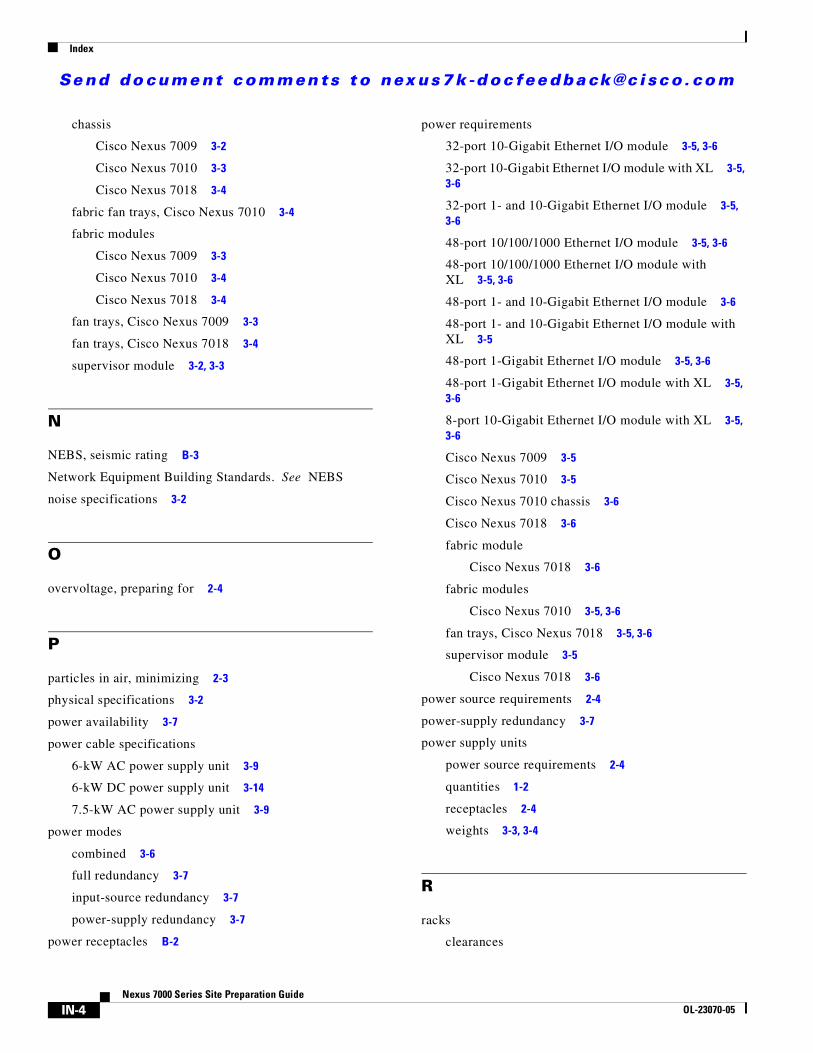
Se nd do cume nt c ommen ts t o nex us7k -d oc fee dba ck@c i sc o . co m
Index
IN-4Nexus 7000 Series Site Preparation Guide
OL-23070-05
chassis
Cisco Nexus 7009 3-2
Cisco Nexus 7010 3-3
Cisco Nexus 7018 3-4
fabric fan trays, Cisco Nexus 7010 3-4
fabric modules
Cisco Nexus 7009 3-3
Cisco Nexus 7010 3-4
Cisco Nexus 7018 3-4
fan trays, Cisco Nexus 7009 3-3
fan trays, Cisco Nexus 7018 3-4
supervisor module 3-2, 3-3
N
NEBS, seismic rating B-3
Network Equipment Building Standards. See NEBS
noise specifications 3-2
O
overvoltage, preparing for 2-4
P
particles in air, minimizing 2-3
physical specifications 3-2
power availability 3-7
power cable specifications
6-kW AC power supply unit 3-9
6-kW DC power supply unit 3-14
7.5-kW AC power supply unit 3-9
power modes
combined 3-6
full redundancy 3-7
input-source redundancy 3-7
power-supply redundancy 3-7
power receptacles B-2
power requirements
32-port 10-Gigabit Ethernet I/O module 3-5, 3-6
32-port 10-Gigabit Ethernet I/O module with XL 3-5, 3-6
32-port 1- and 10-Gigabit Ethernet I/O module 3-5, 3-6
48-port 10/100/1000 Ethernet I/O module 3-5, 3-6
48-port 10/100/1000 Ethernet I/O module with XL 3-5, 3-6
48-port 1- and 10-Gigabit Ethernet I/O module 3-6
48-port 1- and 10-Gigabit Ethernet I/O module with XL 3-5
48-port 1-Gigabit Ethernet I/O module 3-5, 3-6
48-port 1-Gigabit Ethernet I/O module with XL 3-5, 3-6
8-port 10-Gigabit Ethernet I/O module with XL 3-5, 3-6
Cisco Nexus 7009 3-5
Cisco Nexus 7010 3-5
Cisco Nexus 7010 chassis 3-6
Cisco Nexus 7018 3-6
fabric module
Cisco Nexus 7018 3-6
fabric modules
Cisco Nexus 7010 3-5, 3-6
fan trays, Cisco Nexus 7018 3-5, 3-6
supervisor module 3-5
Cisco Nexus 7018 3-6
power source requirements 2-4
power-supply redundancy 3-7
power supply units
power source requirements 2-4
quantities 1-2
receptacles 2-4
weights 3-3, 3-4
R
racks
clearances
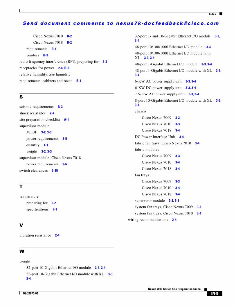
Se nd do cume nt c ommen ts t o nex us7k -d oc fee dba ck@c i sc o . co m
Index
IN-5Nexus 7000 Series Site Preparation Guide
OL-23070-05
Cisco Nexus 7010 B-2
Cisco Nexus 7018 B-2
requirements B-1
vendors B-3
radio frequency interference (RFI), preparing for 2-3
receptacles for power 2-4, B-2
relative humidity. See humidity
requirements, cabinets and racks B-1
S
seismic requirements B-3
shock resistance 2-4
site preparation checklist A-1
supervisor module
MTBF 3-2, 3-3
power requirements 3-5
quantity 1-1
weight 3-2, 3-3
supervisor module, Cisco Nexus 7018
power requirements 3-6
switch clearances 3-15
T
temperature
preparing for 2-2
specifications 3-1
V
vibration resistance 2-4
W
weight
32-port 10-Gigabit Ethernet I/O module 3-3, 3-4
32-port 10-Gigabit Ethernet I/O module with XL 3-3, 3-4
32-port 1- and 10-Gigabit Ethernet I/O module 3-3, 3-4
48-port 10/100/1000 Ethernet I/O module 3-3
48-port 10/100/1000 Ethernet I/O module with XL 3-3, 3-4
48-port 1-Gigabit Ethernet I/O module 3-3, 3-4
48-port 1-Gigabit Ethernet I/O module with XL 3-3, 3-4
6-KW AC power supply unit 3-3, 3-4
6-KW DC power supply unit 3-3, 3-4
7.5-KW AC power supply unit 3-3, 3-4
8-port 10-Gigabit Ethernet I/O module with XL 3-3, 3-4
chassis
Cisco Nexus 7009 3-2
Cisco Nexus 7010 3-3
Cisco Nexus 7018 3-4
DC Power Interface Unit 3-4
fabric fan trays, Cisco Nexus 7010 3-4
fabric modules
Cisco Nexus 7009 3-3
Cisco Nexus 7010 3-4
Cisco Nexus 7018 3-4
fan trays
Cisco Nexus 7009 3-3
Cisco Nexus 7010 3-4
Cisco Nexus 7018 3-4
supervisor module 3-2, 3-3
system fan trays, Cisco Nexus 7009 3-3
system fan trays, Cisco Nexus 7010 3-4
wiring recommendations 2-4

Se nd do cume nt c ommen ts t o nex us7k -d oc fee dba ck@c i sc o . co m
Index
IN-6Nexus 7000 Series Site Preparation Guide
OL-23070-05


![Cisco Nexus 7000 Series Switch Security TargetST] Nexus 7000... · Cisco Nexus 7000 Series Switch Security Target Version 1.0 ... The Nexus 7k switches are modular and are available](https://static.fdocuments.us/doc/165x107/5aa78f6a7f8b9a294b8c4363/cisco-nexus-7000-series-switch-security-target-st-nexus-7000cisco-nexus-7000.jpg)