NEXT Ion Propulsion System Configurations and Performance ... · Performance for Saturn System...
15
1 American Institute of Aeronautics and Astronautics NEXT Ion Propulsion System Configurations and Performance for Saturn System Exploration Scott W. Benson * , John P. Riehl † and Steven R. Oleson ‡ NASA Glenn Research Center, Cleveland, Ohio, 44135 The successes of the Cassini/Huygens mission have heightened interest to return to the Saturn system with focused robotic missions. The desire for a sustained presence at Titan, through a dedicated orbiter and in-situ vehicle, either a lander or aerobot, has resulted in definition of a Titan Explorer flagship mission as a high priority in the Solar System Exploration Roadmap. The discovery of active water vapor plumes erupting from the “tiger stripes” on the moon Enceladus has drawn the attention of the space science community. The NASA’s Evolutionary Xenon Thruster (NEXT) ion propulsion system is well suited to future missions to the Saturn system. NEXT is used within the inner solar system, in combination with a Venus or Earth gravity assist, to establish a fast transfer to the Saturn system. The NEXT system elements are accommodated in a separable Solar Electric Propulsion (SEP) module, or are integrated into the main spacecraft bus, depending on the mission architecture and performance requirements. This paper defines a range of NEXT system configurations, from two to four thrusters, and the Saturn system performance capability provided. Delivered mass is assessed parametrically over total trip time to Saturn. Launch vehicle options, gravity assist options, and input power level are addressed to determine performance sensitivities. A simple two- thruster NEXT system, launched on an Atlas 551, can deliver a spacecraft mass of over 2400 kg on a transfer to Saturn. Similarly, a four-thruster system, launched on a Delta 4050 Heavy, delivers more than 4000 kg spacecraft mass. A SEP module conceptual design, for a two thruster string, 17 kW solar array, configuration is characterized. Nomenclature α 0 , α 1 = optimization constants determined by a mass model C 3 = characteristic energy, km 2 /s 2 I sp = specific impulse, s m final = mass at end of propulsive phase, kg m net = net delivered mass, kg m 0 = predicted initial mass, kg m prop = propellant mass expended, kg m ps = propulsion system mass, kg m tank = propellant tank mass, kg P 0 = initial power, W V hp = hyperbolic excess velocity, km/s V mp = maximum power voltage, V * Aerospace Engineer, Science Project Office, 21000 Brookpark Rd, MS 142-2. † Aerospace Engineer, Mission Analysis Branch, 21000 Brookpark Rd, MS 500-103, AIAA Senior Member. ‡ Aerospace Engineer, Mission Analysis Branch, 21000 Brookpark Rd, MS 500-103, AIAA Senior Member. 43rd AIAA/ASME/SAE/ASEE Joint Propulsion Conference & Exhibit 8 - 11 July 2007, Cincinnati, OH AIAA 2007-5230 This material is declared a work of the U.S. Government and is not subject to copyright protection in the United States.
Transcript of NEXT Ion Propulsion System Configurations and Performance ... · Performance for Saturn System...

1 American Institute of Aeronautics and Astronautics
NEXT Ion Propulsion System Configurations and Performance for Saturn System Exploration
Scott W. Benson*, John P. Riehl† and Steven R. Oleson‡ NASA Glenn Research Center, Cleveland, Ohio, 44135
The successes of the Cassini/Huygens mission have heightened interest to return to the Saturn system with focused robotic missions. The desire for a sustained presence at Titan, through a dedicated orbiter and in-situ vehicle, either a lander or aerobot, has resulted in definition of a Titan Explorer flagship mission as a high priority in the Solar System Exploration Roadmap. The discovery of active water vapor plumes erupting from the “tiger stripes” on the moon Enceladus has drawn the attention of the space science community. The NASA’s Evolutionary Xenon Thruster (NEXT) ion propulsion system is well suited to future missions to the Saturn system. NEXT is used within the inner solar system, in combination with a Venus or Earth gravity assist, to establish a fast transfer to the Saturn system. The NEXT system elements are accommodated in a separable Solar Electric Propulsion (SEP) module, or are integrated into the main spacecraft bus, depending on the mission architecture and performance requirements. This paper defines a range of NEXT system configurations, from two to four thrusters, and the Saturn system performance capability provided. Delivered mass is assessed parametrically over total trip time to Saturn. Launch vehicle options, gravity assist options, and input power level are addressed to determine performance sensitivities. A simple two-thruster NEXT system, launched on an Atlas 551, can deliver a spacecraft mass of over 2400 kg on a transfer to Saturn. Similarly, a four-thruster system, launched on a Delta 4050 Heavy, delivers more than 4000 kg spacecraft mass. A SEP module conceptual design, for a two thruster string, 17 kW solar array, configuration is characterized.
Nomenclature α0, α1 = optimization constants determined by a mass model
C3 = characteristic energy, km2/s2 Isp = specific impulse, s mfinal = mass at end of propulsive phase, kg mnet = net delivered mass, kg m0 = predicted initial mass, kg mprop = propellant mass expended, kg mps = propulsion system mass, kg mtank = propellant tank mass, kg P0 = initial power, W Vhp = hyperbolic excess velocity, km/s Vmp = maximum power voltage, V
* Aerospace Engineer, Science Project Office, 21000 Brookpark Rd, MS 142-2. † Aerospace Engineer, Mission Analysis Branch, 21000 Brookpark Rd, MS 500-103, AIAA Senior Member. ‡ Aerospace Engineer, Mission Analysis Branch, 21000 Brookpark Rd, MS 500-103, AIAA Senior Member.
43rd AIAA/ASME/SAE/ASEE Joint Propulsion Conference & Exhibit8 - 11 July 2007, Cincinnati, OH
AIAA 2007-5230
This material is declared a work of the U.S. Government and is not subject to copyright protection in the United States.

2 American Institute of Aeronautics and Astronautics
I. Introduction HE NASA’s Evolutionary Xenon Thruster (NEXT) ion propulsion system is being developed primarily for NASA robotic science missions, particularly in solar system exploration. Numerous
mission analyses have demonstrated the benefits of electric propulsion, and in particular the NEXT ion propulsion system, for these missions.1-4 The Planetary Science Division of the NASA Science Mission Directorate (SMD) is responsible for planning and implementation of robotic planetary exploration. Planetary science mission priorities are captured in SMD strategic plans and roadmaps. Robotic planetary missions generally fall into three mission classes: Discovery-class, New Frontiers-class and Flagship-class. Discovery-class missions are low-cost, principal investigator (PI)-led, competed missions to inner solar system destinations. New Frontiers-class missions are moderate-cost, PI-led, competed missions to accomplish specific science objectives at various locations across the solar system. Flagship-class missions are high value, comprehensive science missions to targeted destinations. The current solar system exploration roadmap calls for missions to explore the Saturn system in two of these mission classes.5 The Saturn Flyby with Probes mission has recently been added to the list of New Frontiers mission concepts. The roadmap also identifies a Flagship mission to Titan, the largest moon of Saturn, to follow-up on the discoveries of the Cassini-Huygens mission. Flagship mission interest has expanded to include the Saturn moon Enceladus, for which Cassini data has been used to show that it is actively venting water vapor to space. NASA is conducting advanced concept studies of Titan and Enceladus Flagship missions in fiscal year 2007, with plans to continue mission development for promising concepts.
The NEXT ion propulsion system was targeted for Flagship missions to the outer planets at the
beginning of the NEXT project. The In-Space Propulsion Technology project performed an integrated technology application analysis, assessing the breadth of candidate technology concepts across a broad spectrum of NASA science missions. These analyses demonstrated that solar electric propulsion (SEP), in combination with aerocapture at the target body, would be highly beneficial to two specific outer planet missions, a Titan Explorer, consisting of a combination orbiter and lander or aerobot, and a Neptune Orbiter. The results of these analyses were used to specify Deep Space Design Reference Missions for use in defining NEXT performance objectives and development requirements. With the focus of planetary exploration Flagship missions being captured by Project Prometheus in the 2003-2005 timeframe, studies were initiated to assess the application of NEXT, and other ISPT electric propulsion technologies, to Discovery- and New Frontiers-class missions.6,7 This assessment illustrated that NEXT consistently outperformed the state-of-art NSTAR ion propulsion system across the full range of solar system exploration mission classes, substantiating the overall value of the NEXT technology.
The selection process for NASA robotic science missions can be characterized as highly competitive,
whether selected through a directed process or formal competition. It is therefore imperative that advanced technologies are well characterized prior to full consideration for a mission. That characterization consists of analyses and testing to demonstrate system level validation in relevant environments, or Technology Readiness Level 6 (TRL6). Past NASA Discovery, Mars Scout and New Frontiers Announcements of Opportunity have dictated that TRL6 must be demonstrated by the Confirmation Review at the end of the project Phase B, and that the path to accomplish such be fully described in the mission proposal.8,9,10 The NEXT project has performed a thorough range of tests and analyses to validate Technology Readiness Level 6, and to verify that the products meet the project requirements.11 The tests have been predominantly very successful. Several key tests remain, with completion planned in 2007. The NEXT project will have surpassed the key TRL6 milestone prior to initiation of the next rounds of competed mission Announcements of Opportunity, supporting full consideration in mission concept development and proposal.
With the current interest in the Saturn system, and the expected accomplishment of TRL6, the NEXT
team initiated a set of activities to characterize application of the NEXT system to Saturn system missions. Parametric low-thrust trajectory optimization analyses were performed to determine the mission performance provided by NEXT across a broad range of mission and configuration variables. Design concepts for SEP modules were developed through an integrated design center approach to provide a first look at the system configurations necessary to perform these missions. Two specific SEP module concepts were defined: a four-engine, 25 kW power module to maximize mass for Flagship-class missions, and a
T

3 American Institute of Aeronautics and Astronautics
two-engine, 17 kW power module to minimize cost while providing substantive performance for New Frontiers-class missions. Sections II and III of this report describe the parametric performance analyses, Section IV describes the New Frontiers-class SEP module design concept development.
II. Performance Analysis Assumptions & Methodology Any interplanetary mission analysis depends upon a clear statement and understanding of the
requirements and assumptions underlying the mission. These are the requirements that were levied upon the mission analysis:
1. The initial departure epoch is in the 2015 to 2016 time period. Epochs between 2015 and 2025 also are to be achievable, but not necessarily with the same propellant loading.
2. Use a solar electric propulsion (SEP) system consisting of a solar array and power distribution system and an electric propulsion system consisting of some number of thrusters, power processing units, propellant tanks and a distribution system for the propellant.
3. Maximize the injected mass in the vicinity of Saturn while minimizing the hyperbolic excess velocity (Vhp) at Saturn arrival.
4. Use a launch vehicle from the existing fleet of U.S expendable launch vehicles (ELV). The ELV puts the spacecraft on an escape hyperbola.
5. The mission would use a Venus or Earth gravity assist to increase the injected spacecraft mass.
Maximum injected mass is achieved by trajectory optimization. The Vhp is minimized by parametrically
varying the transfer time from earth departure to Saturn arrival. Although it may not be obvious, Vhp decreases with increased trip time until it attains a minimum value and then slowly increases. For this study, the computer program SEPTOP provided the optimization while the utility programs Vartable and Newpost when used with Microsoft Excel permitted quick visualization of the optimization results. SEPTOP, as provided by Carl Sauer of NASA JPL, obtains optimal trajectories using algorithms based upon classical optimal control theory. It has the capability of determining minimal propellant consumption while satisfying the transversality conditions associated the constraints applied on the mission. It even provides the capability of selecting the optimal number of operating thrusters in multiple thruster configurations and of determining the correct throttle setting when presented coefficients of the thruster and mass flow as a function of thrust system input power.
A SEP rendezvous with Saturn is virtually impossible without a final thrusting period near Saturn. Because solar power drops below a minimum level around 3.5 AU, no electric propulsion thrusting is possible near Saturn. Hence, the SEP system essentially puts the spacecraft on a Saturn flyby trajectory. For the Saturn Flyby with Probes mission, this is sufficient, with SEP performing the majority of the mission velocity change required. For spacecraft capture into orbit around Titan or Saturn (for the Enceladus mission), a separate high thrust propulsion system or aerocapture vehicle provides the necessary velocity change.
The following key assumptions were crucial for the analysis of this mission:
1. The launched mass consists of a separable SEP module and a science spacecraft with its own propulsion or aerocapture system for insertion into orbit. This assumption allows for the definition of the SEP system without requiring specific information about the mass or the physical properties of the scientific module.
2. The SEP system model includes a generic solar array whose power output is proportional to the inverse of the square of the distance from the spacecraft to the sun. This assumption provides a degree of conservatism since most solar arrays can provide slightly more power than inverse square because of low incidence and low temperature affects. In addition, array degradation is incorporated into the power model.
3. The propulsion system consists of some number (2 or more) of NEXT thruster “strings”. Each string consists of a thruster and it’s gimbal with the associated power processing unit (PPU) and xenon propellant flow control assembly. A spare thruster string is included; the spare is unused, but is available for contingency operations in the event of off-nominal performance of a primary thruster string. The nomenclature used for the propulsion system is N+1, where N

4 American Institute of Aeronautics and Astronautics
represents the number of thruster strings required for the optimized mission, and the “+1” represents the spare string.
4. The NEXT thruster can be operated across a wide throttle range. This capability has been modeled with curve fits of the extremes of the throttle table, representing either a High Specific Impulse (Isp) mode or High Thrust mode. Based upon the results of a previous study (Ref. 1), the High Isp model for NEXT is assumed to provide a higher final mass than the high thrust setting and was thus used for these analyses
5. The Delta 4240, the Delta 4450, Atlas 551, and the Delta 4050 Heavy expendable launch vehicles were used for this study. The data for the ELV mass models were obtained from the Kennedy Space Center’s web based system. These data were approximated by a polynomial curve fitting procedure to provide injected mass vs. C3 as shown in Fig. 1. The launch vehicle mass model was derated by a factor of 10% to provide a more conservative estimate. Since the KSC performance data assumes a standard payload adapter appropriate for the vehicle, no additional mass was allocated for an adaptor.
6. Planetary fly-by had to be at presumably “safe altitudes” to avoid either a safety hazard or subjection of the spacecraft from high radiation doses. The minimum Earth fly-by altitude analyzed was 1000 km.
7. SEP system operations are assumed to occur with a 90% propulsive duty cycle during thrusting phases. The 10% downtime allows the spacecraft to perform navigation and communications functions on a regular basis.
The parametric performance analysis space is summarized in Table 1. Not all combinations of variables were analyzed. As the analysis progressed, the trade parameters were selected based on knowledge gained. For each case, the trajectory was optimized across a range of trip times, generally from 5 – 9 years, with net delivered spacecraft mass optimized at each trip time. Convergence on a trajectory solution was not always achieved; some results shown in later figures do not cover the entire trip time range.
Figure 1. Expendable Launch Vehicle performance
5 American Institute of Aeronautics and Astronautics
Expendable Launch Vehicles Delta 4240, Delta 4450, Atlas 551, Delta 4050 Heavy
Gravity Assists Venus Gravity Assist, Earth Gravity Assist, Jupiter Gravity Assist A single gravity assist per trajectory
Earth Gravity Assist Altitude 1000 km, 2000 km NEXT Configuration 1+1, 2+1, 3+1 Thruster Strings NEXT Throttle Conditions High specific impulse throttling only Solar Array Power (Beginning of life at 1 AU)
10, 15, 17, 20, 25, 30, 35 kW
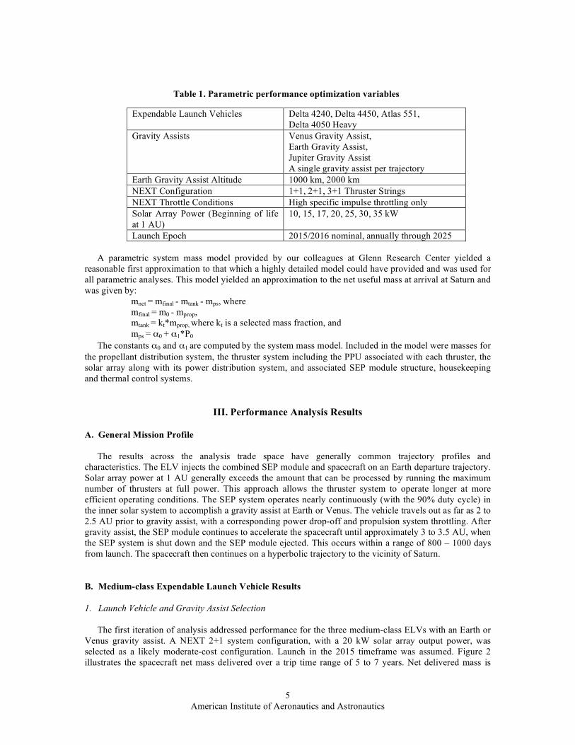
Launch Epoch 2015/2016 nominal, annually through 2025 A parametric system mass model provided by our colleagues at Glenn Research Center yielded a
reasonable first approximation to that which a highly detailed model could have provided and was used for all parametric analyses. This model yielded an approximation to the net useful mass at arrival at Saturn and was given by:
mnet = mfinal - mtank - mps, where mfinal = m0 - mprop, mtank = kt*mprop, where kt is a selected mass fraction, and mps = α0 + α1*P0
The constants α0 and α1 are computed by the system mass model. Included in the model were masses for the propellant distribution system, the thruster system including the PPU associated with each thruster, the solar array along with its power distribution system, and associated SEP module structure, housekeeping and thermal control systems.
III. Performance Analysis Results
A. General Mission Profile The results across the analysis trade space have generally common trajectory profiles and
characteristics. The ELV injects the combined SEP module and spacecraft on an Earth departure trajectory. Solar array power at 1 AU generally exceeds the amount that can be processed by running the maximum number of thrusters at full power. This approach allows the thruster system to operate longer at more efficient operating conditions. The SEP system operates nearly continuously (with the 90% duty cycle) in the inner solar system to accomplish a gravity assist at Earth or Venus. The vehicle travels out as far as 2 to 2.5 AU prior to gravity assist, with a corresponding power drop-off and propulsion system throttling. After gravity assist, the SEP module continues to accelerate the spacecraft until approximately 3 to 3.5 AU, when the SEP system is shut down and the SEP module ejected. This occurs within a range of 800 – 1000 days from launch. The spacecraft then continues on a hyperbolic trajectory to the vicinity of Saturn.
B. Medium-class Expendable Launch Vehicle Results
1. Launch Vehicle and Gravity Assist Selection The first iteration of analysis addressed performance for the three medium-class ELVs with an Earth or
Venus gravity assist. A NEXT 2+1 system configuration, with a 20 kW solar array output power, was selected as a likely moderate-cost configuration. Launch in the 2015 timeframe was assumed. Figure 2 illustrates the spacecraft net mass delivered over a trip time range of 5 to 7 years. Net delivered mass is
Table 1. Parametric performance optimization variables

6 American Institute of Aeronautics and Astronautics
defined as the wet spacecraft mass that remains after separation of the SEP module. This mass is essentially the spacecraft mass at Saturn arrival, minus propellant mass associated with mid-course trajectory correction maneuvers. The trip time reported is the total time from launch to Saturn arrival. A Jupiter gravity assist (JGA) was analyzed only for the Atlas 551; results were significantly less than all other cases, and the JGA was eliminated from further consideration. For this analysis, fly-by altitudes of Earth, Venus, and Jupiter were 1000 km, 300 km, and 1,100,000 km, respectively.
It was determined that a single Earth gravity assist (EGA) was superior to either a Venus or a Jupiter
fly-by. The less massive Venus imparts a smaller velocity increase even though the thruster system operates at a high efficiency level for a considerable duration in preparation for the fly-by and thereby also gains energy. Both Earth and Venus fly-bys are available across the 2015 to 2025 period. The JGA was not available throughout the entire 2015 to 2025 period because Jupiter moved away from an advantageous position for the Saturn mission. The Atlas 551 provides the greatest mission performance capability, as expected, so further analysis focused on this ELV. For future mission studies, ELV selection may favor smaller medium-class vehicles, with reduced performance, if meeting a mission cost cap is a primary constraint.
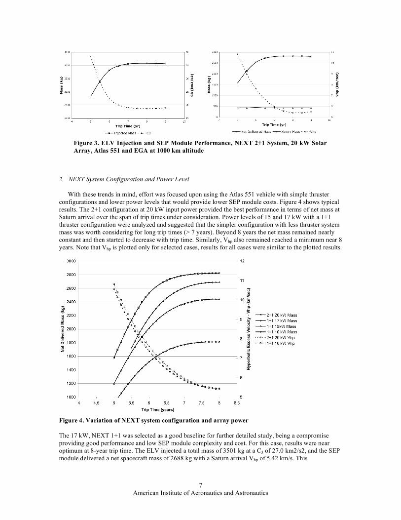
Figure 3 provides an overall perspective of the mass characteristics of this system configuration for the maximum performance Atlas 551/EGA trajectory. Injected mass is defined as the total wet mass of the combined SEP module and spacecraft that is separated from the ELV, and is shown with characteristic energy, or C3. Propellant mass is the total xenon propellant load carried on the SEP module. Spacecraft propellant is not tracked, as this analysis does not specify the Saturn capture approach. The Saturn arrival hyperbolic excess velocity, Vhp, and is a driver for the aerocapture or chemical propulsion system design for the Saturn spacecraft. Generally, minimizing the Vhp at Saturn will reduce the non-usable spacecraft mass associated with capture at the Saturn system. The results show that the net delivered mass has an optimum value of 2822 kg at 7.9-year trip time, and Vhp reaches a minimum of 5.39 km/s at 8.3 years. During initial mission design, it may be desirable to target for a nominal condition with a shorter trip, such that mass margins exist to accommodate vehicle growth and launch window/launch opportunity effects. The trends illustrated in Figure 3 are characteristic results across the entire trade space.
Figure 2. Performance Comparison of Delta 4240, Delta 4450 and Atlas 551, 2+1 NEXT system, 20 kW solar array, Earth Gravity Assist at 1000 km altitude, Venus Gravity Assist at 300 km
7 American Institute of Aeronautics and Astronautics
2. NEXT System Configuration and Power Level
With these trends in mind, effort was focused upon using the Atlas 551 vehicle with simple thruster
configurations and lower power levels that would provide lower SEP module costs. Figure 4 shows typical results. The 2+1 configuration at 20 kW input power provided the best performance in terms of net mass at Saturn arrival over the span of trip times under consideration. Power levels of 15 and 17 kW with a 1+1 thruster configuration were analyzed and suggested that the simpler configuration with less thruster system mass was worth considering for long trip times (> 7 years). Beyond 8 years the net mass remained nearly constant and then started to decrease with trip time. Similarly, Vhp also remained reached a minimum near 8 years. Note that Vhp is plotted only for selected cases, results for all cases were similar to the plotted results.
Figure 4. Variation of NEXT system configuration and array power The 17 kW, NEXT 1+1 was selected as a good baseline for further detailed study, being a compromise providing good performance and low SEP module complexity and cost. For this case, results were near optimum at 8-year trip time. The ELV injected a total mass of 3501 kg at a C3 of 27.0 km2/s2, and the SEP module delivered a net spacecraft mass of 2688 kg with a Saturn arrival Vhp of 5.42 km/s. This
Figure 3. ELV Injection and SEP Module Performance, NEXT 2+1 System, 20 kW Solar Array, Atlas 551 and EGA at 1000 km altitude

8 American Institute of Aeronautics and Astronautics
configuration was also selected for the detailed SEP module definition study, to be described in later sections of this report.
3. Trajectory Characterization The trajectory for the NEXT 1+1, 17 kW, 8-year trip time case is characterized further in Figures 5 and
6. Figure 5 shows the heliocentric trajectory, with the bold line representing the SEP module propulsive phase of the mission. Arrows plotted along this phase indicate the thrust vector required to achieve the optimized trajectory. For the first portion of the trajectory, the applied thrust is shaping the trajectory to increase the effectiveness of the gravity assist. After gravity assist, thrust is applied nearly tangentially to accelerate the vehicle. This particular solution does not have any coast phases during the inner solar system propulsive phase; some solutions do. Figure 6 shows the power profile for this case. Solar array power and power consumed by the PPU/thruster string are shown over the elapsed mission time. The Earth gravity assist occurs at approximately 670 days into the mission, after which the power, and resulting thrust tails off as the spacecraft travels towards Saturn.
Figure 5. NEXT 1+1, 17 kW, 8-year trip heliocentric trajectory
Figure 6. NEXT 1+1, 17 kW power profile

9 American Institute of Aeronautics and Astronautics
Launch flexibility, including launch year capability and launch opportunities and windows of significant
duration, is of primary interest to planetary science mission customers. Optimization of the nominal launch capability across launch dates spanning 10 years revealed that the baseline configuration was capable of delivering roughly similar usable spacecraft masses annually with small variations in arrival hyperbolic excess velocity. (Fig. 7) Furthermore, the required SEP system propellant mass changed very little, while the initial mass after launch did vary. These variations arose from the annual variations in the relative Earth-Saturn geometry that required differing amounts of the Atlas 551 launch capability. Net mass penalties from years 2015 to 2018 can be mitigated by adjusting mission parameters, such as trip time and gravity assist altitude, for each launch year. Launch opportunity capability was addressed in these analyses, but is not presented here. Launch opportunity analysis using SEPTOP requires careful manipulation of constraints and optimization parameters. Results were achieved through several trial cases, with minimal impact to the primary mission capability, but further launch strategy development and analysis is warranted. Detailed launch window analyses have not yet been initiated.
Figure 7. Performance parameters across 10 years of launch opportunity

10 American Institute of Aeronautics and Astronautics
C. Heavy-class Expendable Launch Vehicle Results
1. NEXT System Configuration and Power Level The only launch vehicle considered for the heavy ELV class was the Delta 4050 Heavy. Based on the
results of medium-class vehicle analyses, only the Earth gravity assist was considered. Two NEXT system configurations were analyzed, 2+1 and 3+1, with solar array powers of 20, 25, 30 and 35 kW at 1 AU included for each. Figures 8 and 9 illustrate the results for the 2+1 and 3+1 NEXT system configurations respectively.
Figure 8. Delivered mass and Vhp results at varying array power levels for a NEXT 2+1 configuration, launch on Delta 4050H and an EGA at 1000 km altitude
Figure 9. Delivered mass and Vhp results at varying array power levels for a NEXT 3+1 configuration, launch on Delta 4050H and an EGA at 1000 km altitude

11 American Institute of Aeronautics and Astronautics
The selection of a reference configuration is again a trade between maximum performance and cost. Inspection of the results above illustrate that maximum performance can be achieved with the four thruster configuration and the highest power case. The mission planner can reduce thruster count or reduce array power to reduce SEP module cost with net mass penalties less than 10% and similar arrival Vhp results. The NEXT 3+1 configuration with solar array power of 25 kW at 1 AU was selected for further study.
Figure 10 illustrates the
performance characteristics of this case. For 7.5 years, the ELV injects a total spacecraft mass of 5958 kg at a C3 of 18.5 km2/s2. The SEP module injected a 4154 kg spacecraft with a propellant load of 559 kg and a Saturn arrival Vhp of 5.57 km/s. The effect of Earth fly-by altitude during the gravity assist maneuver was investigated by analyzing that configuration using an altitude of 2000 km. This resulted in a maximum net delivered mass of 3938 kg, a payload decrease of 5.5%. This fly-by altitude sensitivity analysis confirmed the expected trend.
D. Other Findings Thruster propellant through-
put is an important parameter in defining SEP system configurations. Ion thrusters have known wear mechanisms that are directly related to the amount of propellant expended, thus throughput is a primary measure of thruster life. The NEXT thruster has a mission-need based throughput requirement of 300 kg xenon. Current testing and analysis indicate the thruster has considerably more lifetime capability; the first failure mode is predicted to occur after more than 730 kg of xenon expended.12 With a 1.5 qualification factor, this indicates the NEXT thruster has a rated capability of over 480 kg xenon. Throughput per thruster was assessed for all optimization runs over the trade space described above. The required throughput per thruster ranged from a low of 182 kg for the 3+1, 20 kW case, to a high of 311 kg for the 2+1, 35 kW case. The reference 1+1, 17 kW and 3+1, 25 kW cases have required throughputs of 286 kg and 204 kg per thruster respectively. Throughput required was generally well below the current requirement of 300 kg xenon across the cases analyzed.
Figure 10. ELV Injection and SEP Module Performance, NEXT 3+1 System, 25 kW Solar Array, Delta 4050H and EGA at 1000 km altitude

12 American Institute of Aeronautics and Astronautics
IV. Solar Electric Propulsion Module Definition
A. Background and Point of Departure A detailed conceptual design for two SEP modules was developed through the NASA GRC
Collaborative Modeling for Parametric Assessment of Space Systems (COMPASS) team. The COMPASS team is a multidisciplinary collaborative engineering team whose primary purpose is to perform integrated vehicle systems analysis and provide trades and designs for NASA missions. The team developed conceptual designs for the NEXT 1+1/17 kW/Atlas 551 mission, described in detail here, and the NEXT 3+1/25 kW/Delta 4050 Heavy mission.
The design approach for the SEP module was based on past SEP spacecraft (Deep Space One and Dawn), outer planetary probes (Cassini), and launch vehicle adapters. Each of these systems either drove or influenced the design. The top-level design guidelines included:
- New Frontiers-Class or Flagship-Class Spacecraft. The spacecraft was not defined in detail, but was volumetrically sized based on prior spacecraft. The spacecraft is assumed to provide it’s own radioisotope power.
- Provide the spacecraft with the primary propulsion required to place it on a 7-year trajectory to Saturn.
- Rely on the spacecraft for certain functions to reduce redundant systems (and costs) between the SEP module and spacecraft (i.e. control, communications, attitude control).
- Utilize off-the-shelf equipment where possible to minimize costs - Single fault tolerant - SEP module doubles as the launch interface (structural) between the ELV and the spacecraft - Mass Growth (contingency) based on ANSI/AIAA R-020A-1999, additional growth carried at
system level to total 30% for the module
B. NEXT 1+1, 17 kW SEP Module Configuration The deployed SEP module (Fig. 11) and representative spacecraft are dominated by the large single
axis, solar arrays to collect the power to operate a single NEXT thruster throughout the trajectory. Two thrusters are flown with one a cold spare. Gimbals on the thruster provide thrust vector pointing and yaw and pitch control. Radiators are placed on the SEP module face just below the solar array drive assemblies so that they can view deep space during NEXT thruster operation. The spacecraft is represented by the cylinder and antenna dish in the figure.
Figure 11. Deployed 1+1, 17 kW SEP module
13 American Institute of Aeronautics and Astronautics
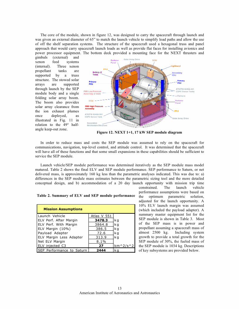
The core of the module, shown in figure 12, was designed to carry the spacecraft through launch and
was given an external diameter of 65” to match the launch vehicle to simplify load paths and allow the use of off the shelf separation systems. The structure of the spacecraft used a hexagonal truss and panel approach that would carry spacecraft launch loads as well as provide flat faces for installing avionics and power processor equipment. The bottom deck provided a mounting face for the NEXT thrusters and gimbals (external) and xenon feed systems (internal). Three xenon propellant tanks are supported by a truss structure. The stowed solar arrays are supported through launch by the SEP module body and a single folding solar array boom. The boom also provides solar array clearance from the ion exhaust plumes once deployed, as illustrated in Fig. 11 in relation to the 49° half-angle keep-out zone.
In order to reduce mass and costs the SEP module was assumed to rely on the spacecraft for
communications, navigation, top-level control, and attitude control. It was determined that the spacecraft will have all of these functions and that some small expansions in these capabilities should be sufficient to service the SEP module.
Launch vehicle/SEP module performance was determined iteratively as the SEP module mass model
matured. Table 2 shows the final ELV and SEP module performance. SEP performance to Saturn, or net delivered mass, is approximately 160 kg less than the parametric analyses indicated. This was due to: a) differences in the SEP module mass estimates between the parametric sizing tool and the more detailed conceptual design, and b) accommodation of a 20 day launch opportunity with mission trip time
constrained. The launch vehicle performance assumptions were based on the optimum parametric solution, adjusted for the launch opportunity. A 10% ELV launch margin was assumed (which included the payload adapter). A summary master equipment list for the SEP module is shown in Table 3. Most of the SEP mass is in power and propellant assuming a spacecraft mass of almost 2500 kg. Including system growth to provide a total growth for the SEP module of 30%, the fueled mass of the SEP module is 1034 kg. Descriptions of key subsystems are provided below.
Figure 12. NEXT 1+1, 17 kW SEP module diagram
Table 2. Summary of ELV and SEP module performance
Mission Assumptions
Launch Vehicle Atlas V 551
ELV Perf. After Margin 3478.3 k g
ELV Perf. With Margin 3864.8 k g
ELV Margin (10%) 386.5 k g
Payload Adapter 72.6 k g
ELV Margin Less Adapter 313.9 k g
Net ELV Margin 8.1%
ELV injected C3 27 km^2/s^2
SEP Performance to Saturn 2444 k g

14 American Institute of Aeronautics and Astronautics
Spacecraft System details
Master Equipment List -- Mass CBE (kg) Growth (kg)Total Mass
(kg)
% of dry
mass
Science Probe N/A N/A 2444 N/A
SEP Stage N/A
Avionics and Comm 10.2 2.0 12.2 1.9%
GN&C 0.8 0.4 1.2 0.2%
Electrical Power 276.6 44.2 320.8 50.2%
Thermal Control 32.7 5.9 38.6 6.0%
Structures 82.6 14.9 97.5 15.3%
Propulsion 152.9 15.5 168.4 26.4%
Propellant 311.7 0.0 311.7 N/A
SEP Stage Total Mass w/o system Growth 867.5 82.9 950.3
SEP Stage dry mass 555.8 82.9 638.7
SEP Stage Inert Mass 558.9 N/A 641.8
SEP Stage Total Mass w/ system Growth 83.9 1034.2
System Level Growth (Contingency) Tracking
Dry Mass Growth (contingency) 14.9%
Desired Total Growth (Contingency) 30%
Desired Total Growth (Contingency) Mass 166.7 k g
System Level Growth (Contingency) 83.9 k g
C. SEP Module Subsystems
1. Propulsion System The propulsion system consists of a 1+1 gimbaled 7 kW NEXT ion propulsion system. NEXT ion
propulsion system functionality and schematic diagrams are described in Ref. 13. The xenon propellant is stored in three carbon over-wrapped pressure vessels. Propulsion system mass may be reduced by designing a new, single xenon tank.
2. Power System
The key element of the power system is the two solar arrays at 9350 W (@1 AU) each, including 10% for margin (array degradation over the trajectory is included in the 9350 W). Each solar array is populated with triple-junction solar cells, with the PV cells arranged in series strings to provide Vmp of 100 Vdc at 1 AU. Strings are arranged in groups to provide 5% to 50% of array power at the primary Power Distribution Unit (PDU) so that unusable power at 1 AU can be shunted. As the SEP module moves further from the sun on its trajectory, more of each array is switched in to control the input power to the ion propulsion system. The single fault tolerance requirement drove the power management and distribution system to use cross-tied redundant primary PDUs.
3. Thermal Control System
Cooling of the NEXT power processing units, power distribution units and avionics was provided by passive heat pipes to radiator panels mounted on the solar array boom faces. This ensures that the radiators see deep space (and not the sun) during NEXT operation. The spacecraft was wrapped in MLI to retain heat and the xenon tank and lines had minimal heaters to avoid condensing the xenon. A multi-layer MLI shield was provided on the thruster/gimbal bulkhead to prevent the heat from the NEXT thrusters to soak back into the spacecraft.
4. Command and Data Handling
In order to save costs the Digital Control Interface Unit (DCIU), which normally just controls the NEXT system, was expanded to control all the SEP module systems from commands from the main spacecraft processors. Thus the DCIU would perform the complex commands of turning on/off and throttling the thrusters but the inputs to perform these operations would come from the spacecraft computer. In the same way the DCIU would gimbal the solar arrays based on pointing commands from the spacecraft. All navigation, guidance and attitude control commands would come from the spacecraft.
Table 3. NEXT 1+1, 17 kW SEP module mass summary

15 American Institute of Aeronautics and Astronautics
V. Future Work The parametric analyses presented here provide a broad range of ion propulsion performance
characteristics. As mission concepts become better defined, it will be beneficial to execute the optimization analyses for more specific mission parameters and assumptions. Additional analysis of launch opportunity and launch window capabilities will be important in characterizing system performance commitments for higher level events, such as support to a mission proposal submittal. The COMPASS SEP module concept is also a valuable departure point for more detailed mission and vehicle definition.
VI. Conclusions Parametric trajectory optimization analyses have demonstrated that a NEXT ion propulsion system-
based solar electric propulsion module can deliver substantive spacecraft mass on a transfer trajectory to Saturn over a broad range of launch vehicle, gravity assist and system configuration options. Xenon throughput required per thruster was seen to be well within predicted NEXT thruster capability, providing ample life margins. SEP module conceptual designs were generated, providing validation of a technical approach, as well as the adequacy of performance estimates using parametric SEP module sizing.
The Saturn system is of primary interest for upcoming NASA planetary mission opportunities, both competed and directed. The NEXT ion propulsion system provides capabilities that should be evaluated in detail in developing the concepts for these challenging missions.
References 1 Oleson, S., Gefert, L., Benson, S., Patterson, M., Noca, M., Sims, J., Mission Advantages of NEXT: NASA’s
Evolutionary Xenon Thruster, AIAA-2002-3969, 38th Joint Propulsion Conference, Indianapolis, IN, July 2002. 2 Cupples, M. “Application of Electric Propulsion to a Comet Sample Return Mission,” AIAA 2004-3804, 40th Joint
Propulsion Conference, Fort Lauderdale, FL, July 2004. 3 Oh, D. Y., Benson, S. W., Witzberger, K. E., and Cupples, M., “Deep Space Mission Applications for NEXT:
NASA’s Evolutionary Xenon Thruster,” 40th Joint Propulsion Conference, Ft. Lauderdale, FL, July 2004. 4 Witzberger, K. E., “Solar Electric Propulsion for Primitive Body Science Missions,” 53rd JANNAF Propulsion
Meeting, Monterrey, CA, December 2005. 5 “Solar System Exploration”, NASA, JPL D-35618, Pasadena, CA, September 15, 2006. 6 Oh, D. Y., “Evaluation of Solar Electric Propulsion Technologies for Discovery Class Missions,” AIAA-2005-
4270, 41st Joint Propulsion Conference, Tucson, AZ, July 2005. 7
Witzberger, K., Benson, S., Manella, D., Oh, D., Brophy, J. and Cupples, M. “NASA’s 2004 In-Space Propulsion Re-Focus Studies for New Frontiers Class Missions,” AIAA-2005-4271, 41st
Joint Propulsion Conference, Tucson, AZ, July, 2005.
8 “Announcement of Opportunity Discovery Program 2006 and Missions of Opportunity,” NNH06ZDA001O, NASA, Washington, DC, January 2006.
9 “Announcement of Opportunity Mars Scout Program 2006 and Missions of Opportunity,” NNH06ZDA002O, NASA, Washington, DC, May 2006.
10 “Announcement of Opportunity New Frontiers Program 2003 and Missions of Opportunity,” AO 03-OSS-03, NASA, Washington, DC, October 2003.
11 Benson, S. W., Patterson, M. J., “Progress in Technology Validation of the NEXT Ion Propulsion System,” 54th JANNAF Propulsion Meeting, Denver, CO, May 2007.
12 Herman, D. A., Soulas, G. C., Patterson, M. J., “Status of the NEXT Ion Thruster Long-Duration Test after 10,200 hr and 207 kg Demonstrated,” AIAA-2007-5272, 43rd Joint Propulsion Conference, Cincinnati, OH, July 2007.
13 Benson, S. W., Patterson, M. J., Vaughan, D. A., Wilson, A. C., Wong, B. R., “NASA’s Evolutionary Xenon Thruster (NEXT) – Phase 2 Development Status,” AIAA-2005-4070, 41st Joint Propulsion Conference, Tucson, AZ, July 2005.