Next Generation Multimedia Multicast Services - CORE · Agradecimento final ao Núcleo de Ténis da...
123
Universidade de Aveiro 2011 Departamento de Electrónica, Telecomunicações e Informática Luis André Silva Cruz Pinho Serviços Multimédia Multicast de Próxima Geração Next Generation Multimedia Multicast Services
-
Upload
truongtram -
Category
Documents
-
view
214 -
download
0
Transcript of Next Generation Multimedia Multicast Services - CORE · Agradecimento final ao Núcleo de Ténis da...

Universidade de Aveiro
2011 Departamento de Electrónica, Telecomunicações e Informática
Luis André Silva Cruz Pinho
Serviços Multimédia Multicast de Próxima Geração Next Generation Multimedia Multicast Services
Universidade de Aveiro 2011
Departamento de Electrónica, Telecomunicações e Informática
Luis André Silva Cruz Pinho
Serviços Multimédia Multicast de Próxima Geração Next Generation Multimedia Multicast Services
Dissertação apresentada à Universidade de Aveiro para cumprimento dos requisitos necessários à obtenção do grau de Mestre em Engenharia Electrónica e Telecomunicações, realizada sob a orientação científica do Doutor Francisco Fontes, Professor Convidado do Departamento de Electrónica, Telecomunicações e Informática da Universidade de Aveiro.

i
Dedico este trabalho aos meus pais e à minha irmã.
iii
presidente Prof. Dr. Rui Luís Andrade Aguiar
professor associado com agregação da Universidade de Aveiro
Prof. Dra. Marília Pascoal Curado
professora auxiliar do Departamento de Engenharia Informática da Faculdade de Ciências e
Tecnologia da Universidade de Coimbra
Prof. Dr. Francisco Manuel Marques Fontes
professor auxiliar convidado da Universidade de Aveiro
o júri
Prof. Doutor Rui Luís Andrade Aguiar Professor Associado com Agregação da Universidade de Aveiro Profª. Doutora Marília Pascoal Curado Professora Auxiliar do Departamento de Engenharia Informática da Faculdade de Ciências e Tecnologia da Universidade de Coimbra Prof. Doutor Francisco Manuel Marques Fontes Professor Auxiliar Convidado da Universidade de Aveiro

iv

v
agradecimentos
Um agradecimento especial ao meu orientador, Doutor Francisco Fontes e ao Engenheiro Filipe Cabral Pinto pelo apoio, disponibilidade e paciência demonstrada ao longo desta dissertação. Agradeço também a toda a comunidade académica e a tudo que a rodeia, ao meu departamento de Electrónica, Telecomunicações e Informática e ao Instituto de Telecomunicações que me permitiu frequentar nos últimos meses deste trabalho as suas instalações. Agradecimento final ao Núcleo de Ténis da Associação Académica da Universidade de Aveiro, ao qual também pertenço, por todo o apoio. Um agradecimento especial aos meus pais e à irmã por todo o apoio demonstrado e em que nos momentos de dificuldade sempre depositaram em mim total confiança.

vii
palavras-chave UMTS, IMS, MBMS, Multicast, SIP, Mobicents, Servlets
resumo
Uma das mais recentes conquistas na evolução móvel foi o 3G, permitindo o acesso a serviços multimédia com qualidade de serviço assegurada. No entanto, a tecnologia UMTS, tal como definida na sua Release ’99, é apenas capaz de transmitir em modo unicast, sendo manifestamente ineficiente para comunicações multimédia almejando grupos de utilizadores.
A tecnologia IMS surge na Release 5 do 3GPP que começou a responder já a algumas necessidades, permitindo comunicações sobre IP oferecendo serviços Internet a qualquer momento e em qualquer lugar sobre tecnologias de comunicação móveis fornecendo pela primeira vez sessões multimédia satisfatórias. A Release 6 por sua vez trouxe a tecnologia MBMS que permite transmissões em broadcast e multicast para redes móveis. O MBMS fornece os serviços de aplicações multimédia que todos estavam à espera, tanto para os utilizadores como para os prestadores de serviços. O operador pode agora fazer uso da tecnologia existente aumentando todo o tipo de benefícios no serviço prestado ao cliente. Com a possível integração destas duas tecnologias passa a ser possível desenvolver serviços assentes em redes convergentes em que os conteúdos são entregues usando tecnologias unicast, multicast ou broadcast. Neste contexto, o principal motivo deste trabalho consiste essencialmente em fazer uso dos recursos da rede terminando com o desperdício dos mesmos e aumentando a eficiência dos serviços através da integração das tecnologias IMS e MBMS.
O trabalho realizado começa com o estudo do estado da arte das telecomunicações móveis com referência às tecnologias referidas, seguindo-se a apresentação da possível integração IMS-MBMS e terminando com o projecto de uma plataforma de demonstração que no futuro possa ser uma implementação de serviço multimédia multicast. O objectivo principal é mostrar os benefícios de um serviço que era normalmente executado em unicast relativamente ao modo multicast, fazendo uso da nova convergência de tecnologias IMS e MBMS. Na conclusão do trabalho são referidas as vantagens do uso de portadoras multicast e broadcast, tendo como perspectiva de que este trabalho possa ser um ponto de partida para um novo conjunto de serviços poupando recursos de rede e permitindo uma eficiência considerável em serviços inovadores.

viii

ix
keywords
UMTS, IMS, MBMS, Multicast, SIP, Mobicents, Servlets
abstract
3G is bang up to date in the mobile phone industry. It allows access to multimedia services and gives a guarantee of quality of service. The UMTS technology, defined in 3GPP Release ’99, provides an unicast transmission, but it is completely inefficient when it comes to multimedia group communications.
The IMS technology first appeared in Release 5 that has already started to consider the interests of the clients. It provides communications over IP, offering Internet services anytime, anywhere on mobile communication technologies. Also, it offers for the first time satisfactory multimedia sessions. On the other hand, Release 6 gave rise to the MBMS technology that provides broadcast and multicast transmissions for mobile networks. The MBMS provides multimedia applications services that everyone was waiting, including users and service providers. Now the operator makes use of existing technology in order to provide better costumer services. The possible integration of these two technologies will contribute to develop services based on converged networks in which contents are delivered through the unicast, multicast or broadcast technologies. Therefore, the objective of this work is basically to make use of network resources avoiding wastes and improving customer services through the integration of the IMS and the MBMS technologies.
The executed work starts with the mobile telecommunications state of the art with reference to the referred technologies, followed by the IMS-MBMS convergence presentation and finishing with the proposal for implementation of a service platform that can be used for a multimedia multicast service. The main point is to show the benefits of a service that has been normally executed in unicast mode over the multicast mode, making use of the new IMS and MBMS technologies integration. To closure the work it is referred the advantages to use multicast and broadcast bearers, with the perspective that this work could be a starting point to a new set of services, saving network resources and allowing for innovate services a considerable efficency.

x
xi
Acronyms
1G First Generation
2G Second Generation
3G Third Generation
3GPP 3rd Generation Partnership Project
4G Fourth Generation
AAA Authentication, Authorization and Accounting
AMPS American Mobile Phone System
API Application Programming Interface
APN Access Point Name
ATM Asynchronous Transport
BCMCS Broadcast and Multicast Service
BGCF Breakout Gateway Control Function
BICC Bearer Independent Call Control
BM-SC Broadcast Multicast – Service Center
BTS Base Transceiver Station
CAMEL Customized Applications for Mobile networks using Enhanced Logic
CDMA Code Division Multiple Access
CGI Common Gateway Interface
CN Core Network
COPS Common Open Policy Service
CRM Customer Relationship Management
CRNC Controlling Radio Network Controller
CS Circuit Switched
CSCF Call Session Control Function
D-AMPS Digital – American Mobile Phone System
DCCA Diameter Credit-Control Application
DHCP Dynamic Host Configuration Protocol
DMB Digital Multimedia Broadcasting
DNS Domain Name System
DRNC Drift Radio Network Controller
DSL Digital Subscriber Line
DVB-H Digital Video Broadcasting – Handheld
EDA Event Driven Architecture
EDGE Enhanced Data Rates for Global Evolution
EIR Equipment Identity Register
EJB Enterprise JavaBeans
EPC Evolved Packet Core
EPS Evolved Packet System

xii
E-UTRAN Evolved UMTS Transport Radio Access Network
FDD Frequency Division Duplex
FTP File Transfer Protocol
GERAN GSM Edge Radio Access Network
GGSN Gateway GPRS Support Node
GMSC Gateway Mobile Switching Center
GPRS General Packet Radio Service
GSM Global System for Mobile Communications
gsmSCF GSM Service Control Function
HLR Home Location Register
HSDPA High-Speed Downlink Packet Access
HSS Home Subscriber Server
HSUPA High-Speed Uplink Packet Access
HTTP Hypertext Transfer Protocol
ICC Integrated Circuit Card
IETF Internet Engineering Task Force
IGMP Internet Group Management Protocol
IMEI International Mobile station Equipment Identities
IMPI IP Multimedia Private Identity
IMPU IP Multimedia Public Identity
IM-SSF IP Multimedia – Service Switching Function
IMS IP Multimedia Subsystem
IMS-ALG IMS Application Layer Gateway
IMS AS IMS Application Server
IMSI International Mobile Subscriber Identifier
IMS-OMA IP Multimedia Subsystem – Open Mobile Alliance
IN Intelligent Network
IP Internet Protocol
IP-CAN IP Connectivity Access Network
IPv4 Internet Protocol version 4
IPv6 Internet Protocol version 6
ISC IMS Service Control
ISDN Integrated Services Digital Network
ISIM IP Multimedia Services Identity Module
ISP Internet Service Provider
ISUP ISDN User Part
I-WLAN Interworking – Wireless Local Area Network
J2EE Java 2 Platform Enterprise Edition
JEE Java Enterprise Edition
JMX Java Management Extensions
JSLEE Java Service Logic Execution Environment

xiii
JSP JavaServer Pages
LIA Location Info Answer
LIR Location Info Request
LTE Long Term Evolution
NAI Network Access Identifier
NAPT-PT Network Address Port Translator – Protocol Translator
NAS Network Access Application
NASREQ Network Access Application Requirements
NAT Network Address Translation
NAT-PT Network Address Translation – Protocol Translation
NGN Next Generation Networks
NMS Network Management Subsystem
NMT Nordic Mobile Telephone
NNI Network-to-Network Interface
NSAPI Netscape Server Application Programming Interface
NT Network Termination
MAA Multimedia Authentication Answer
MAP Mobile Application Part
MAR Multimedia Authentication Request
MBMS Multimedia Broadcast Multicast Service
MB-SE Multicast/Broadcast – Service Enabler
MDF Media Delivery Function
MDFC Media Delivery Function Controller
MDFP Media Delivery Function Processor
ME Mobile Equipment
MediaFLO Media Forward Link Only
MGCF Media Gateway Controller Function
MGW Media Gateway
MIMO Multiple-Input Multiple-Output
MLD Multicast Listener Discovery
MM Mobility Management
MMS Multimedia Message Service
MRF Media Resource Function
MRFC Media Resource Function Controller
MRFP Media Resource Function Processor
MS Mobile Station
MSC Mobile Switching Center
MSIDSN Mobile Station International Subscriber Directory Number
MSS Mobile SIP Servlets
MT Mobile Termination
PCEF Policy Control Enforcement Function

xiv
PCM Pulse Code Modulation
PCRF Policy Charging and Rules Function
PDC Personal Digital Cellular
PDF Policy Decision Function
PDN Public Data Network
PDP Policy Decision Point
PDP Packet Data Protocol
PEP Policy Enforcement Point
PLMN Public Land Mobile Network
PMM Packet Mobility Management
PoC Push over Cellular
PS Packet-Switched
PSI Public Service Identity
PSTN Public Switched Telephone Network
QoE Quality of Experience
QoS Quality of Service
OFDMA Orthogonal Frequency Division Multiple Access
OFDM Orthogonal Frequency Division Multiplexing
OMA Open Mobile Alliance
OSA-SCS Open Service Access – Service Capability Server
OSS Operations Support Systems
RA Routing Area
RADIUS Remote Authentication Dial In User Service
RAN Radio Access Network
RNC Radio Network Controller
RNS Radio Network Sub-System
RRC Radio Resource Control
RT Radio Termination
RTCP Real-Time Transport Control Protocol
RTP Real-Time Transport Protocol
SAE Service Architecture Evolution
SAES System Architecture Evolution Specification
SBB Service Building Blocks
SC-FDMA Single Carrier – Frequency Division Multiple Access
SCP Service Control Point
SCTP Stream Control Transmission Protocol
SDP Session Description Protocol
SDP Service Delivery Platforms
SEG Security Gateway
SGSN Serving GPRS Support Node
SGW Serving Gateway
xv
SIM Subscriber Identity Module
SIP Session Initiation Protocol
SIP AS SIP Application Server
SIP B2BUA SIP Back-to-Back User Agent
SLF Subscriber Location Function
SMS Short Message Service
SMS-PP Short Message Service – Point to Point
SMTP Simple Mail Transfer Protocol
SNMP Simple Network Management Protocol
SOA Service-Oriented Architecture
SRNC Serving Radio Network Controller
SS7 Signaling System no. 7
TACS Total Access Communication System
TCP Transmission Control Protocol
TDD Time Division Duplex
TDMA Time Division Multiple Access
TE Terminal Equipment
THIG Topology Hiding Inter-network Gateway
TMGI Temporary Mobile Group Identity
TrGW Transition Gateway
TSG Technical Specification Group
TSG CT TSG Core Network and Terminals
TSG GERAN TSG GSM/EDGE Radio Access Network
TSG RAN TSG Radio Access Network
TSG SA TSG Service and System Aspects
UA User Agent
UAA User Authentication Answer
UAR User Authentication Request
UDP User Datagram Protocol
UE User Equipment
UICC Universal Integrated Circuit Card
UNI User-to-Network Interface
UMTS Universal Mobile Telecommunications System
UMTS OSA UMTS Open Service Access
URI Uniform Resource Identifier
URL Uniform Resource Locator
USIM Universal Subscriber Identity Module
US-TDMA IS-136, one of the second-generation systems mainly in USA
UTRA UMTS Terrestrial Radio Access
UTRAN UMTS Terrestrial Radio Access Network
VLR Visitor Location Register

xvi
VoIP Voice over IP
WAP Wireless Application Protocol
WCDMA Wideband Code Division Multiple Access
WiMAX Worldwide Interoperability for Microwave Access
WLAN Wireless Local Access Network
XML Extensible Markup Language

xvii
Table of Contents Acronyms .................................................................................................................... xi
Table of Contents .................................................................................................... xvii
List of Figures ............................................................................................................ xxi
List of Tables ............................................................................................................ xxv
Chapter 1. Introduction .......................................................................................... 1
1.1. Motivation ............................................................................................. 1
1.2. Objectives .............................................................................................. 2
1.3. Contribution ........................................................................................... 2
1.4. Layout .................................................................................................... 3
Chapter 2. State of the Art...................................................................................... 5
2.1. Introduction ........................................................................................... 5
2.2. 3GPP - 3rd Generation Partnership Project .............................................. 6
2.2.1. Introduction ............................................................................... 6
2.2.2. 3GPP Releases............................................................................ 8
2.3. 3G Architecture Evolution .................................................................... 10
2.3.1. Introduction ............................................................................. 10
2.3.2. UMTS System Architecture ...................................................... 10
2.4. IMS (IP Multimedia Subsystem) ............................................................ 17
2.4.1. Introduction ............................................................................. 17
2.4.2. IMS Concepts, Fundamentals and Requirements ..................... 19
2.4.3. IMS Architecture ...................................................................... 21
2.4.4. SIP and other IMS Protocols ..................................................... 33
2.4.5. IMS Identification ..................................................................... 40
2.4.6. Session Control in IMS.............................................................. 41
2.5. MBMS (Multimedia Broadcast Multicast Service) ................................. 46
2.5.1. Introduction ............................................................................. 46
2.5.2. MBMS Architecture.................................................................. 46
2.5.3. MBMS Multicast Mode ............................................................ 47
2.5.4. MBMS Broadcast Mode ........................................................... 49
2.5.5. BM-SC (Broadcast Multicast – Service Center) ......................... 50

xviii
2.5.6. Other Entities for MBMS support ............................................. 50
2.5.7. MBMS Attributes and Parameters............................................ 52
2.5.8. MBMS Procedures ................................................................... 53
Chapter 3. IMS – MBMS Integration ..................................................................... 61
3.1. Introduction ......................................................................................... 61
3.2. Expectations ......................................................................................... 62
3.3. Convergence Architecture .................................................................... 62
3.3.1. Architecture basics................................................................... 63
3.3.2. IMS session signaling and MBMS bearer services blend ........... 64
3.4. Technology Integration ........................................................................ 69
3.4.1. Release 7 and 8 Integration ...................................................... 69
3.4.2. Logical Perspective ................................................................... 70
3.5. IMS-MBMS Architecture evolved.......................................................... 71
3.5.1. Architectural Topics ................................................................. 71
3.5.2. Functions Integration ............................................................... 71
3.5.3. Convergent Architecture .......................................................... 73
3.6. IMS-MBMS Signaling procedures .......................................................... 76
3.6.1. Service Activation .................................................................... 76
3.6.2. Session Start ............................................................................ 77
3.6.3. Session Stop ............................................................................. 78
3.6.4. Service Deactivation................................................................. 79
3.7. Multicast/Broadcast Services Evolution ................................................ 80
3.8. Briefing................................................................................................. 81
Chapter 4. Service Architecture ............................................................................ 83
4.1. Proposed Service Description ............................................................... 83
4.2. Mobicents / JBoss ................................................................................ 84
4.2.1. Mobicents SIP Servlets Server .................................................. 84
4.2.2. JBoss Application Server .......................................................... 85
4.3. HTTP & SIP Servlets .............................................................................. 85
4.3.1. HTTP Servlets ........................................................................... 85
4.3.2. SIP Servlets .............................................................................. 87

xix
4.3.3. SIP and HTTP Servlets differences ............................................ 89
4.4. Implementation ................................................................................... 90
Chapter 5. Conclusions & Future Work................................................................. 93
5.1. Conclusions .......................................................................................... 93
5.2. Future Work ......................................................................................... 93
Bibliography .............................................................................................................. 95

xx

xxi
List of Figures
Figure 2.1 – Mobile subscribers’ growth .................................................................................... 5
Figure 2.2 – IMS basic concept .................................................................................................. 6
Figure 2.3 – 3GPP Releases timeline .......................................................................................... 7
Figure 2.4 – Structure of 3GPP .................................................................................................. 7
Figure 2.5 – Data peak rate evolution ........................................................................................ 9
Figure 2.6 – PLMN network elements ...................................................................................... 11
Figure 2.7 – Logical role of the RNC ......................................................................................... 13
Figure 2.8 – UMTS CN Architecture Release 5.......................................................................... 15
Figure 2.9 – UMTS terminal ..................................................................................................... 15
Figure 2.10 – SIM in GSM and 3G ............................................................................................ 17
Figure 2.11 – IMS Architecture ................................................................................................ 18
Figure 2.12 – S-CSCF routing ................................................................................................... 23
Figure 2.13 – Different AS’s types and relations ...................................................................... 24
Figure 2.14 – Terminating SIP UA providing services in the originating leg ............................... 25
Figure 2.15 – Terminating SIP UA providing services in the terminating leg ............................. 25
Figure 2.16 – Application Server as originating SIP UA ............................................................. 25
Figure 2.17 – SIP proxy server providing services in the originating side .................................. 26
Figure 2.18 – SIP proxy server providing services in the termination side ................................ 26
Figure 2.19 – SIP redirect server providing services in the termination side ............................. 27
Figure 2.20 – SIP B2BUA logic .................................................................................................. 27
Figure 2.21 – SIP B2BUA providing services in the origination side .......................................... 28
Figure 2.22 – SIP B2BUA providing services in the termination side ......................................... 28
Figure 2.23 – Example of a service .......................................................................................... 28
Figure 2.24 – Logical Gateway ................................................................................................. 29
Figure 2.25 – BGCF and PSTN/CS gateway in IMS-CS network interface ................................... 30
Figure 2.26 – IPv4 / IPv6 Interworking ..................................................................................... 30

xxii
Figure 2.27 – IPv4 / IPv6 NAT .................................................................................................. 31
Figure 2.28 – IMS-ALG / TrGW relation.................................................................................... 31
Figure 2.29 – P-CSCF in the visited network ............................................................................. 32
Figure 2.30 – P-CSCF and GGSN in the home network ............................................................. 32
Figure 2.31 – Registrar and Proxy at the same logical level ...................................................... 34
Figure 2.32 – Registrar and Proxy as separate roles ................................................................. 34
Figure 2.33 – Forking proxy operation ..................................................................................... 35
Figure 2.34 – Redirect server operation .................................................................................. 35
Figure 2.35 – INVITE-ACK transaction ...................................................................................... 36
Figure 2.36 – CANCEL transaction ........................................................................................... 36
Figure 2.37 – Session establishment through a SIP proxy. ........................................................ 37
Figure 2.38 – Hop-by-hop and end-to-end transmission .......................................................... 38
Figure 2.39 – Basic Diameter and Applications ........................................................................ 38
Figure 2.40 – Authentication and Authorization IMS Architecture ........................................... 39
Figure 2.41 – IP connectivity in GPRS....................................................................................... 41
Figure 2.42 – Registration at the IMS level .............................................................................. 42
Figure 2.43 – Session Setup without services provisioning ....................................................... 45
Figure 2.44 – MBMS Reference Architecture ........................................................................... 46
Figure 2.45 – MBMS Multicast mode phases ........................................................................... 47
Figure 2.46 – Broadcast mode phases ..................................................................................... 49
Figure 2.47 – MBMS Bearer Context State Model .................................................................... 52
Figure 2.48 – MBMS Multicast Service Activation .................................................................... 54
Figure 2.49 – MBMS Session Start procedure for U-TRAN/UTRAN for EPS ............................... 55
Figure 2.50 – MBMS Registration procedure ........................................................................... 56
Figure 2.51 – MBMS Session Stop procedure for E-UTRAN and UTRAN for EPS ........................ 57
Figure 2.52 – MBMS De-Registration procedure initiated by the BM-SC .................................. 58
Figure 2.53 – MBMS Multicast Service Deactivation ................................................................ 59

xxiii
Figure 2.54 – Session Update procedure ................................................................................. 59
Figure 3.1 – Converged Broadcast/Multicast Architecture by the C-MOBILE project ................ 63
Figure 3.2 – Architecture of IMS applications using MBMS as a bearer .................................... 64
Figure 3.3 – IMS applications using MBMS as a bearer flow..................................................... 64
Figure 3.4 – IMS multicast service direct delivery signaling flows............................................. 66
Figure 3.5 – Unicast to Multicast bearer switching signaling flows ........................................... 67
Figure 3.6 – Bearer switching flows from multicast to unicast originated by the UE ................. 68
Figure 3.7 – Integration Architecture with distributed BM-SC functionalities ........................... 70
Figure 3.8 – Logical Framework of C-MOBILE project research ................................................ 70
Figure 3.9 – Functional entities of BM-SC ................................................................................ 72
Figure 3.10 – Evolved IMS-MBMS architecture ........................................................................ 74
Figure 3.11 – IMS and MBMS convergence details .................................................................. 76
Figure 3.12 – Service Activation Procedure in the integration view.......................................... 77
Figure 3.13 – Session Start procedure ..................................................................................... 78
Figure 3.14 – Session Stop Procedure ...................................................................................... 79
Figure 3.15 – Service Deactivation Procedure .......................................................................... 79
Figure 3.16 – Functional Structure of the Broadcast/Multicast Service Enabler (MB-SE) .......... 80
Figure 4.1 – High-level proposed service architecture ............................................................. 83
Figure 4.2 – Mobicents logo, The Open Source SLEE and SIP Server ......................................... 84
Figure 4.3 – JBoss Application Server logo ............................................................................... 85
Figure 4.4 – The role of the middle layer ................................................................................. 85
Figure 4.5 – SIP Servlet Overview ............................................................................................ 88
Figure 4.6 – First Web page for user data insertion, HTTP servlet related ................................ 91

xxiv

xxv
List of Tables Table 1 – SIP servlet request/response methods ..................................................................... 88
Table 2 – SIP servlet objects and interfaces. ............................................................................ 89

xxvi
Next Generation Multimedia Multicast Services Chapter 1. Introduction
1
Chapter 1. Introduction
1.1. Motivation The development of the mobile telecommunications systems until the third-generation (3G) has
been made in stages. The first generation (1G) consists in analog cellular systems1, the second
generation (2G) such as Global System for Mobile Communications (GSM) enabled compatibility
and international transparency and offered besides the traditional speech service some data
services and Internet access making it possible to say that was the transition for digital systems2.
The third generation (3G) of mobile systems such as Universal Mobile Telecommunications
System (UMTS) was mainly designed for multimedia services taking benefit of higher transfer data
rates. With the arrival of the 3G mobile systems with UMTS in a previously Release ’99 of the
Third Generation Partnership Project (3GPP), it is important to notice the IP Multimedia
Subsystem (IMS) technology appearing in release 5 of 3GPP. With the IMS technology is allowed
the operators to provide multimedia services and connectivity between users that uses the same
control and charging mechanisms. With the basic capacities of the Session Initiation Protocol (SIP)
it is possible to establish peer-to-peer sessions. Looking forward is possible to say that the fourth
generation (4G) of wireless communications systems, as a new concept of mobile
communications, it is the stage that succeeds the third generation and has the attraction of
100Mbit/s for high mobility and 1Gbit/s for low mobility communication maintaining the Quality
of Service (QoS) to allow services at any moment anywhere. 4G systems are expected to provide
secure all-IP based mobile broadband solutions to all devices with wireless capacities, and will
provide to the users besides the obviously great Internet access, IP telephony, gaming services
and multimedia streaming. The main goals of the 4G are the convergence of a large variety of
services that were only available on fixed broadband, the low costs and all the advantages that
the society can profit with the improvement of the related services [1].
The short introduction above about the evolution of the telecommunications systems is the
starting point to the idea of this work. The amazing evolution of the systems capacities and all
that we can take from it brings us the creation of good and useful services for the users.
Mobile communications evolved from the basics of the point-to-point voice services to more
complex services with point-to-multipoint. The broadcast or multicast transmissions are the
mechanisms to send data from one data source to multiple destinations. The multicast
communication gives us a large branch of service applications as information dissemination,
multimedia conferencing, shared whiteboards, multicast file transfer, multiparty games and
distributed computing.
1 First generation networks were incompatible with each other and only able to offer basic voice services (AMPS, NMT and TACS).
2 PDC (2G system in Japan), D-AMPS, cdmaOne (IS-95) and US-TDMA (IS-136) are also second generation mobile systems.

Next Generation Multimedia Multicast Services Chapter 1. Introduction
2
To support mobile broadcast and multicast, some alternatives are developed but it is the
Multimedia Broadcast Multicast Service (MBMS) that is the focus of this work3.
The MBMS technology as will be checked after in this document appears in the Release 6 of 3GPP.
The step forward to achieve a converged network based on all-IP support infrastructure is an
integrated architecture to provide broadcast and multicast services and applications, which is the
integration of the IMS and the MBMS technologies [2]. Before this integration the IMS technology
alone was providing QoS for a good experience to the user of enriched multimedia services in
General Packet Radio Service (GPRS) and UMTS but without the all new experience that IMS and
MBMS will achieve and even more when both technology will work together.
Finally a last word about the motivation for the realization of this work is supported in perceived
desire of the operators to create fresh and personalized services. For that the keys are social
networks and Mobile TV. To make it possible the operators have to use instead of the unicast
bearers, multicast and broadcast bearers which will make possible to improve in many the future
services. Another key element of future work is context information to provide personal services,
which consists on information used to improve the system efficiency where context-aware
systems process collected information from the user and which will help to select the better
service based on its environment [3].
1.2. Objectives The main objective of this thesis is the study and the starting point of a service based on the
integration of IMS and MBMS systems. The first phase of this work is to understand the evolution
of all the technology until the point that we are now and in the second phase to develop the
beginning of a multicast service and to show the differences over a unicast communication in a
future work.
1.3. Contribution The main point of this work is to give use to the great capacities of the integrated technology that
is explained after in chapter 3. It will make possible to the operators offer services based on new
tech and make profits by using the technology that they have at its disposal in a better and more
efficient way. With the IMS alone it was not possible to perform multicast services, so the
contribution of this work is to show how to begin an example of a multicast service that has been
possible to be made after the appearing of the MBMS technology. The use of the MBMS
technology allows multicast and broadcast transmissions but it is the multicast way that gives to
the operator all the profit in future services, due to the broadcast mode exists in open channel.
The beginning of a multicast service that will be developed in this thesis can act as a starting point
of a new generation of services such as context-aware services.
3 DVB-H and DMB as broadcast, MBMS and BCMCS as broadcast and multicast and Media Flow Link Only (MediaFLO) as proprietary are
another solutions.

Next Generation Multimedia Multicast Services Chapter 1. Introduction
3
1.4. Layout This dissertation is organized in five chapters.
Chapter 1 gives us a small introduction of what the dissertation is about and what is the objective
to be achieved at the end of it.
Chapter 2 introduces all 3GPP releases and what relevant items were introduced in which one.
The evolution and transformation of the technologies architectures is the second main point of
this chapter starting in the UMTS architecture and finishing in the IMS and MBMS architecture.
Chapter 3 is the main part if this thesis. It will give us the major event of this evolution, the
integration of the IMS with the MBMS technology that permits all new kind of services.
Chapter 4 is the final part of this thesis. It documents the implementation work. Before that, there
is an introduction of what is needed to implement to make possible such implementation, which
are the server that is used and the kind of programming. At the end of the chapter is presented
the results of the implementation to show the objectives accomplishment.
Chapter 5 presents conclusions about the work done and identifies that work that can be done in
the near future based on this research and work that can be upgraded with a step forward.


Next Generation Multimedia Multicast Services Chapter 2. State of the Art
5
Chapter 2. State of the Art
2.1. Introduction The number of mobile subscribers has a tremendous growth during the last decade and with an
exponentially estimation for the future. It is expected more than one million new subscribers per
day added, globally. This growth is showed in Figure 2.1, where the worldwide mobile phone
permeation arrives to the 60%. This mobile penetration is relative because some users have more
than one subscription and one subscription can be used by several users. The voice
communication preferred method is, without a doubt, the mobile. The mobile networks cover
already 90% of the world population because of the low cost mobile phones and the efficiency on
the network capacity and coverage, which is only possible with a large of several standardized
solutions. These standardizations are being developed since more than a decade, allowing also to
the low income users to enjoy the benefits from being always connected. So, to deliver all the
time more new services the technology has to evolve fast and innovative. [4]
Figure 2.1 – Mobile subscribers’ growth
The GSM is the first communications technology that is worth it to mention as having efficiently
created voice services to deliver. The UMTS as the third generation systems appeared with a
flexible service delivery, not requiring a particular optimization of the network. The radio solution,
Wideband Code Division Multiple Access (WCDMA), presented for that technology allowed new
services due to new abilities: (i) high data rates (2Mbps from Release ’99 until 10Mbps from
Release 5), (ii) delays in round trip time below 200ms, (iii) mobility for packet switched
applications, (iv) QoS differentiation for high efficiency of services delivery, (v) voice and data
simultaneous capacity and (vi) GMS/GPRS existing networks interconnection. New categories of
services had emerged: person-to-person, content-to-person, business connectivity, localization
services and IMS.
0%
10%
20%
30%
40%
50%
60%
70%
0
1000
2000
3000
4000
5000
6000
7000
1998 1999 2000 2001 2002 2003 2004 2005 2006 2007 2008
Pen
etra
tio
n
Mill
ion
s
World Population Mobile Subscribers Penetration
Next Generation Multimedia Multicast Services Chapter 2. State of the Art
6
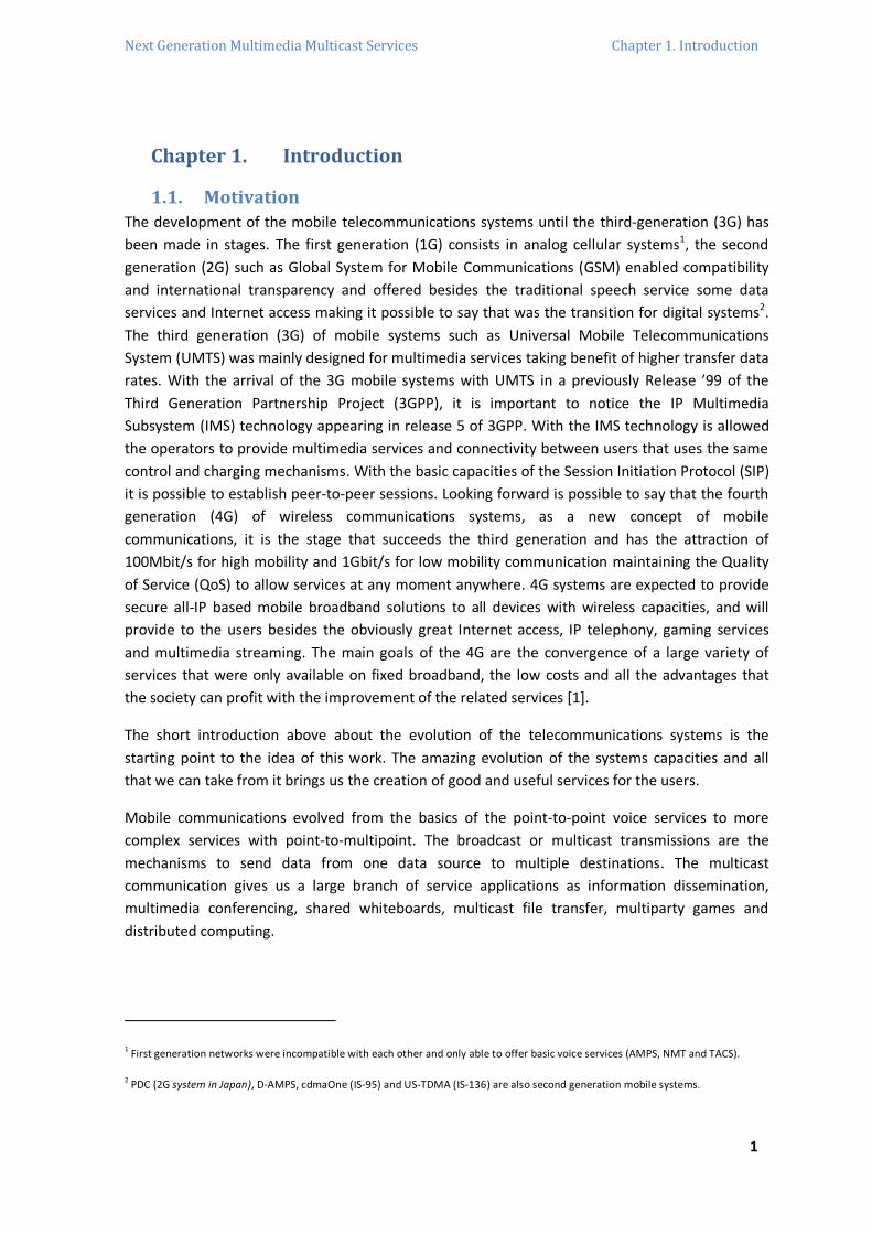
The IMS allows the network operators the provision of new multimedia services and the
anticipation of the performance at the final user. The same platform can be used for real-time
services (Voice over IP - VoIP4) and for non-real-time services (Content Sharing). The concept of
the IMS is illustrated in Figure 2.2, where SIP is the protocol chosen to control a session, and the
technology is explained in detail later on this Chapter. [5]
WCDMA network
IP MultimediaCore
SIP
IP Multimedia core finds the other terminal and connects
the terminals with IP.
Peer-to-peer IP connection between
terminals
SIP
Figure 2.2 – IMS basic concept
2.2. 3GPP - 3rd Generation Partnership Project
2.2.1. Introduction
The 3rd Generation Partnership Project (3GPP) is a collaboration agreement established in 1998
and brings together several telecommunications standards bodies. The technology normalizations
for third generation systems are made since the first release of the WCDMA until the Evolved
UMTS Terrestrial Radio Access Network (E-UTRAN)5 technology, which is the air interface of 3GPP
Long Term Evolution (LTE) specification upgrade path for mobile networks.
The 3GPP was responsible for the standardization of GSM/EDGE (Enhanced Data Rates for Global
Evolution), which was the original scope to produce globally applicable Technical Specifications
and Reports for a 3G Mobile System based on evolved GSM core networks and the radio access
technologies that they support, such as UMTS Terrestrial Radio Access (UTRA) both Frequency
Division Duplex (FDD) and Time Division Duplex (TDD) modes. The background of 3GPP come from
a long time ago and the WCDMA was chosen in several locations as the reference technology for
the 3G of wireless communications systems. The creation of 3GPP was due to the non-global
standardization of the WCDMA around the world which lead several countries for the
establishment of the 3GPP. So, the first big publication was the final specification version of the
Release ’99 which included all the specifications of the WCDMA. In Figure 2.3 is illustrated the
Releases timeline, where the Release 11 is still to an unknown date. [6]
4 VoIP is a technology that allows phone calls made over Internet networks converting analog voice signals into digital data packets.
VoIP supports real-time and bidirectional conversational transmissions using Internet Protocol and whose implementations are based
on the H.323 technology standards. This technology saves costs over traditional long distance telephone calls. The disadvantages are
the frequent dropped calls and the lower voice quality.
5 E-UTRAN substitutes the HSDPA and HSUP technologies of the UMTS specified in 3GPP Release 5 and beyond. It is an entirely new air
interface and it is WCDMA unrelated and incompatible. Provide higher data rates, lower latency and packet data optimized. It uses
Orthogonal Frequency Division Multiplexing (OFDM) radio-access (method of digital modulation in which a signal is divided into several
narrowband channels at different frequencies) and Multiple-Input Multiple-Output (MIMO) antenna technology for downlink to
support more users.

Next Generation Multimedia Multicast Services Chapter 2. State of the Art
7
1999 2012
2000
2001 2002 2003 2004 2005 2006 2007 2008 2009 2010 2011
Mar 00
Release'99
Mar 01
Release 4
Jun 02
Releasse 5
Dez 08
Release 8
Dez 09
Release 9
Mar 11
Release 10
Set 12
Release 11Dez 04
Release 6
Jun 07
Release 7
Figure 2.3 – 3GPP Releases timeline
The organizational structure of 3GPP has four different Technical Specification Groups:
TSG Radio Access Network (TSG RAN) – responsible for the definition of functions, requirements
and interfaces of the UTRA/E-UTRA in its two modes, FDD and TDD. As the 3G systems has to be
based on new wide band, multimode and flexible radio access, this approach ensures that
systems will be capable of rapid development and deployment of competitive service offerings
while still enabling global roaming.
TSG Core Network and Terminals (TSG CT) – responsible for specifying the user equipment,
signaling between core network nodes, external networks correlation, GPRS between network
entities, Wireless Local Area Network (WLAN) – UMTS interworking and descriptions of IMS, SIP
Call Control, Session Description Protocol (SDP) for the IMS, mapping of QoS and interfaces
specific to the UMTS Open Service Access (UMTS OSA).
TSG Service and System Aspects (TSG SA) – responsible for all the architecture and service
capabilities of systems based on 3GPP specifications, and also has the responsibility for cross TSG
co-ordination.
TSG GSM/EDGE Radio Access Network (TSG GERAN) – responsible for the specification of the
radio access part of GSM/EDGE because the related operators need a strategy growth and
interoperability.
The TSGs are illustrated in Figure 2.4, which shows the 3GPP structure.
Project Co-ordination Group (PCG)
TSG GERAN TSG RAN TSG SA TSG CT
GSM EDGERadio Access Network
Radio Access Network Service and Systems Aspects Core Network and Terminals
GERAN WG1 SA WG1Radio Aspects Radio Layer 1 spec Services MM/CC/SM (iu)
GERAN WG2Protocol Aspects
RAN WG2Radio Layer 2 spec
GERAN WG3Terminal Testing RAN WG3
Iub spec, Iur spec, Iu spec
RAN WG4Radio Performance
RAN WG5Mobile Terminal
SA WG2Architecture
SA WG3
Security
SA WG4Codec
CT WG2
Interworking with external networks
CT WG3
MAP/GTP/BCH/SS
GERAN WG1Smart Card Application
RAN WG1 CT WG1
Radio Layer 3 RR spec
UTRAN O&M requirements
Protocol Aspects
Conformance Testing
SA WG5
Telecom Management
Organizational Partners
Representation
Individual Partners
Figure 2.4 – Structure of 3GPP

Next Generation Multimedia Multicast Services Chapter 2. State of the Art
8
Also, the division of the TSGs into Working Groups is showed where each of the Working Groups
is allocated particular tasks which are referred also in the illustration. The 3GPP organization
creates the technical content of specifications6. However, the ones who publish the work are the
partner organizations, which allow the existence of specifications sets, identical in all regions,
ensuring roaming between continents.
This introduction is based on [6] [4] [7].
2.2.2. 3GPP Releases
The 3GPP starts in 1998, which major releases are shown in Figure 2.3 with published data
starting from the first WCDMA release, Release ‘99, and covering the releases that followed. A
brief description of each release follows:
Release ‘99 – basic WCDMA features with theoretical data rates up to 2Mbps, based on the
different multiple accesses for FDD and TDD operation. It has the final specifications and new
resources for GSM and UMTS and resources adaptions between technologies. So, the major point
for this release is the GSM-UMTS architecture and the development of the new radio access
network UTRAN.
Release 4 – 3GPP abandoned the previous release principals. Without WCDMA features, this
release contain the new low chip rate TDD version for the TDD mode of UTRA. In this release an
introduction of resources to an all-IP Core Network (CN) appears. Improvements and
optimizations for GSM and UMTS systems, such as the transport in UTRAN, CN and radio
interface. The introduction of the Mobile Switching Center Server (MSC Server) is also a key point.
Release 5 – High-Speed Downlink Packet Access (HSDPA)7 and IMS are the key points. This release
brings improvements on the radio interface, RAN, GERAN, transport in UTRAN with the IP
transport, support of IPv6, security, positioning of the User Equipment (UE) for Packet-Switch
(PS)/GPRS, extended streaming and WCDMA in 1800/1900MHz frequency spectrums.
Release 6 – High-Speed Uplink Packet Access (HSUPA)8 for WCDMA and the MBMS are the most
important introductions in this release. WCDMA/WLAN interworking, common Radio Resource
Management (UTRAN/GERAN), PS streaming services, Multimedia Messaging Service (MMS) and
enhancements in the IMS, such as Push over Cellular (PoC), are other improvements.
6 The 3GPP specification covers all GSM (including GPRS and EDGE), WCDMA and LTE (with also LTE-Advanced) specifications. Also
covers the descriptions of networks using 3G specifications, such as UTRAN and UMTS. [6]
7 HSDPA is a resource based on a shared downlink channel, only for data, which allows rate data transmission until 10Mb/s.
8 HSUPA was created due to the increasing of IP services. Also the the needing of coverage, transmission and uplink delays
improvements are also reasons. New services had to appear providing high-speed communications for services such as video
conference and mobile email.
Next Generation Multimedia Multicast Services Chapter 2. State of the Art
9
Release 7 – introduction of several HSDPA, HSUPA and MBMS enhancements. The rise of spectral
efficiency of radio interface is of utmost importance with the MIMO antenna which is a key
element to the evolution of the UMTS radio interface. Other improvements are terminal location
services, interconnection between WLAN and UMTS and new resources for IMS.
Release 8 – reformulation of the UMTS based on an all-IP network. Besides the enhancements of
the IMS and RAN, the main contents of this release are: 3GPP System Architecture Evolution
Specification – Evolved Packet System (SAES), the first release of the LTE (RAN part), Home NodeB
and Home eNodeB9, WLAN interworking with a 3GPP system (I-WLAN) and in-vehicle emergency
call (eCall).
Release 9 – among other things there are enhancements in the Home NodeB/eNodeB, IMS and
SAES. New implementations are: the support for IMS Emergency Calls over GPRS and Evolved
Packet System (EPS), MBMS support in EPS, Worldwide Interoperability for Microwave Access
(WiMAX) and LTE/UMTS interoperability.
The further releases until the present moment are essentially improvements and enhancements
in UTRA, LTE Advanced and GERAN. [6]
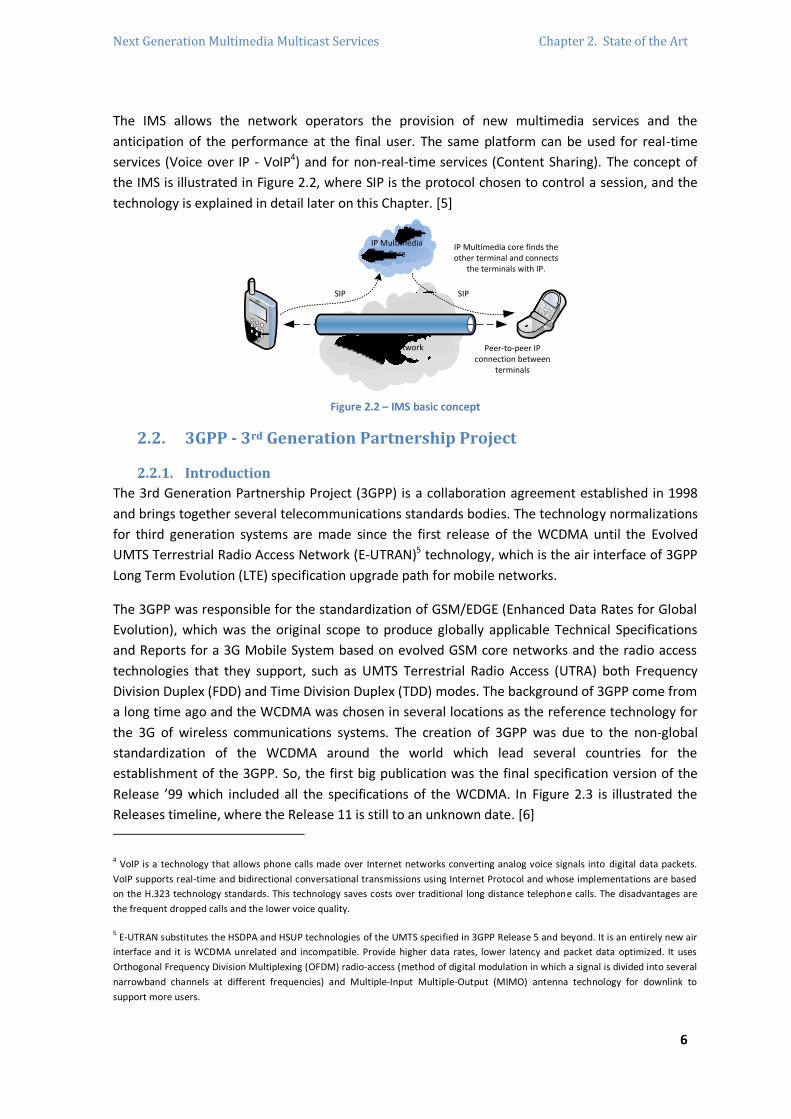
The technology evolution brings data rates higher and higher during the years, which brings the
possibility of a great evolution of new services taking advantage of the radio interface evolution.
This peak user data rates evolution is illustrated in Figure 2.5. It is possible to see that between
the first WCDMA deployments in 2002 until the LTE in 2010, the data rate is more than 300 times
higher over 8 years. The technologies were designed for an easy interworking/existence, where
LTE supports bi-directional handovers between LTE and GSM and also UMTS. So LTE, UMTS and
GSM are able to share network elements including core network elements.
EDGE WCDMA HSPA HSPA+ LTE LTE 4x4
472 kbps 2 Mbps 14 Mbps 42 Mbps 150 Mbps 300 Mbps
Theoretical peak data rate
Figure 2.5 – Data peak rate evolution
9 “Home NodeB and Home eNodeB” refers to the deployment as small UTRA and E-UTRA cells in domestic environments. The Home
NodeB/eNodeB interconnects with 3G core/Evolved Packet Core (EPC) over a fixed broadband such as DSL or cable. [6]

Next Generation Multimedia Multicast Services Chapter 2. State of the Art
10
2.3. 3G Architecture Evolution
2.3.1. Introduction
The evolution from 2G to 3G covers the technical part of the network elements, but also the
expansion of the network architecture and services. This evolution begins in the GSM, through
GPRS and arrives at the UMTS. The GSM has good quality of voice, low prices of terminals and
services, international roaming, spectral efficiency and compatibility with Integrated Services
Digital Network (ISDN). To upgrade the GSM, also known as 2.5G, the GPRS appears to allow PS
traffic and two additional services nodes are brought to the mobile network: Serving GPRS
Support Node (SGSN) and Gateway GPRS Support Node (GGSN). The GPRS is the first step of
wireless point-to-point structures.
This chapter consists in an overview of the UMTS architecture, which is an evolution from the
GPRS system. The UMTS uses the same architecture of all the main previous systems.
The generic architecture incorporates two main domains: the User Equipment Domain
(equipment used by the user to access UMTS services having a radio interface to the
infrastructure) and the Infrastructure Domain (physical nodes, which perform the functions
required to terminate the radio interface and to support the telecommunication services
requirements of the users).
2.3.2. UMTS System Architecture
The UMTS architecture consists on a number of logical network elements grouped on similar
functionalities or based on which sub-network they belong to. The definition of the network
elements can be made at logical level, but the result is a similar physical implementation,
especially since there is some number of open interfaces10. The network elements are grouped
into: (i) UTRAN, which handles with all radio related functions, (ii) CN which is responsible for
external networks connectivity and for routing and switching calls, and (ii) UE which interfaces
with the user and where the radio interface is defined.
The UE and the UTRAN consists on completely new protocols due to the new WCDMA radio
technology requirements, but the CN is adopted from the GSM and GPRS. This adaptation with
the new radio technology gave to the system a fast introduction in the telecommunication
systems with new advantages, such as the global roaming11. [5]
10 An open interface is the one that is defined in such detailed level that the end user equipment can be from different manufactures.
11 Roaming is the user ability from a given operator network to have connectivity in a different location from where is registered. It is
connected in a visited network.

Next Generation Multimedia Multicast Services Chapter 2. State of the Art
11
2.3.2.1. Logical Networks Elements
The UMTS system can be divided in sub-networks which are distinguished from each other with a
unique entity. A sub-network is called UMTS Public Land Mobile Network (PLMN)12 and it is
normally operated by a single operator and has connectivity with the other sub-networks as well
as other types of networks such as ISDN, Public Switched Telephone Network (PSTN) and Internet.
Figure 2.6 is an illustration of PLMN elements, their connections and the external networks that
can be connected to. The following it is a presentation of all elements.
Internet
PLMN, PSTN,ISDN
External Networks
GGSNSGSN
GMSC
HLR
MSC/VLR
CN
UTRAN
RNC
RNC
Iur
Iu
Node B
Node B
Node B
Node B
Iub
UE
ME
USIM
Cu Uu
RNS
RNS
Iu C
S
Iu P
S
Figure 2.6 – PLMN network elements
The UE is divided in two parts: the Mobile Equipment (ME) is the radio terminal to establish the
radio communications and the Universal Subscriber Identity Module (USIM) is the smartcard
which is inside the physical terminal and it holds user and subscription information.
The UTRAN is divided in two parts as well: the NodeB is involved in radio resource management
and has the task of converting the data flow between the Iub and Uu interfaces and the Radio
Network Controller (RNC) is the service access point for the services that the UTRAN provides to
the CN, controlling the radio resources of its own domain.
The logical elements belonging to the CN, which already appeared in the GSM architecture, are:
Home Location Register (HLR) – database located in the system of the user which keeps the user
profile information which is created when the user subscribe to the system and remain until the
subscription is deactivated. In the HLR is also stored the UE location data on the level of the
serving system, meaning SGSN or MSC/VLR level.
12 PMLN is any wireless communication system intended to be used by terrestrial subscriber in vehicles or on foot.

Next Generation Multimedia Multicast Services Chapter 2. State of the Art
12
Mobile Switching Center/Visitor Location Register (MSC/VLR) – it is a switch and a database,
respectively, which works for the related UE for Circuit-Switched (CS) services. The MSC is
responsible for switching CS transactions and the VLR function is mainly to keep the visitor user
profile information.
Gateway Mobile Switching Center (GMSC) – it is the switch responsible for the connection
between the UMTS PLMN with external CS networks. All the connections with CS external
networks have to pass through by the GMSC.
Serving GPRS Support Node (SGSN) – it has a similar function to the MSC/VLR, but it is used for PS
services. The SGSN support is needed for the early UE handling operation and it is involved with
mobility and communication management, whose basic procedure is the forwarding of a call to
the actual location of the ME. It delivers packets to the ME of the respective service area and
request user profiles to the HLR. It detects new terminals, processes them and holds their
location.
Gateway GPRS Support Node (GGSN) – it is used as an interface to connect with external IP
networks. It holds necessary routing information as it makes the mapping of addresses and
subscribers monitoring. One or more GGSNs can support multiple SGSNs.
The external networks are divided in two groups: CS networks which provide CS connections and
the PS networks which are the ones that lead with packet data services such as the Internet. [5]
2.3.2.2. Open Interfaces
The main open interfaces are also illustrated in Figure 2.6, between the logical network elements.
Those interfaces are: (i) the Cu interface which is the electrical interface between the smartcard
and the mobile equipment itself following the specific normalizations, (ii) the Uu interface is the
WCDMA radio interface and connects the UE with the fixed part of the system, (iii) the Iu interface
is the connection between the UTRAN and the CN, (iv) the Iub interface connects the NodeB and
one RNC and (v) the Iur interface permits the soft-handover between different RNCs from
different manufacturers complementing the Iu interface. [5]
2.3.2.3. UTRAN (UMTS Terrestrial Radio Access Network)
The UTRAN architecture is showed in the second square of the Figure 2.6 and it consists in one or
more Radio Network Sub-System (RNS). A RNS is a sub-network inside the UTRAN and has one
RNC and one or more NodeB, where the Iur interfaces RNCs and the Iub interfaces the connection
between the RNC and one or more NodeBs. The requirements and characteristics for the UTRAN
design are mainly the UTRA functionalities support, the support for soft handover, management
of the WCDMA, maximization as much as possible with GSM for PS and CS data transport
mechanism and after the Release 5 of 3GPP the IMS substitute the Asynchronous Transport (ATM)
as the transport mechanism. [5]
Next Generation Multimedia Multicast Services Chapter 2. State of the Art
13
2.3.2.3.1. RNC (Radio Network Controller)
The RNC controls the radio resources of UTRAN, interfaces with the CN by one MSC or one SGSN
and terminates the Radio Resource Control (RRC) protocol which defines messages and
procedures between UE and UTRAN. The RNC which controls the NodeB is known as the
Controlling RNC (CRNC) of that NodeB and it is responsible for the load and congestion control. It
also executes the admission control and channel allocation for the new radio links that will be
establish in its own cells. In the case that a connection using more than one RNS, the RNC is
divided in two separate logical roles: (i) Serving RNC (SRNC) is the RNC that terminates the Iu
connection for the data user transport and also terminates the signaling protocol between the UE
and the UTRAN, and one UE has just one associated SRNC. (ii) Drift RNC (DRNC) is any RNC besides
SRNC which controls the cells used by the UE and it does not mean that it is always associated to a
DRNC for a UE. Those roles are normally inside one physical RNC.
Other RNC functions are: control power adjustments, handover13 control, macro-diversity,
segmentation and reassembly, broadcast signaling and open loop power control.
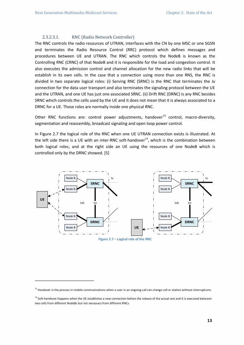
In Figure 2.7 the logical role of the RNC when one UE UTRAN connection exists is illustrated. At
the left side there is a UE with an inter-RNC soft-handover14, which is the combination between
both logical roles, and at the right side an UE using the resources of one NodeB which is
controlled only by the DRNC showed. [5]
DRNC
SRNC
Iur
IuNode B
Node B
Node B
Node B
IubUE
DRNC
SRNC
Iur
IuNode B
Node B
Node B
Node B
Iub
UE
Figure 2.7 – Logical role of the RNC
13 Handover is the process in mobile communications when a user in an ongoing call can change cell or station without interrupti ons.
14 Soft-handover happens when the UE establishes a new connection before the release of the actual one and it is executed between
two cells from different NodeBs but not necessary from different RNCs

Next Generation Multimedia Multicast Services Chapter 2. State of the Art
14
2.3.2.3.2. NodeB (Base Station)
The NodeB is the transmission/reception radio unit for communications between radio cells. One
NodeB can provide services to one or more cells and each NodeB can physically co-exist with a
BTS15 to save costs in the GSM-UMTS adaptation. The NodeB connects with the UE via Uu
interface using WCDMA and can support both FDD and TDD. The main function of the NodeB is
the data conversion on the Uu radio interface which includes the error detection and data rate
transmission adaptation in the air interface. The NodeB also monitors the quality, the correction
strength and calculates the error rate, transmitting this information to the RNC for processing.
This entity also allows the UE to settle its power using the power control in the downlink
transmission technique. The logical model of the NodeB consists of a common control port,
common signaling link and a set of traffic termination points, which are controlled by one
dedicated control point16. [5]
2.3.2.4. UMTS Core Network
The CN Release ’99 presented two domains: CS and PS domain covering all the different kind of
traffic needs. Such architecture is showed in the Figure 2.6, where all the showed entities can co-
exist in the same physical entity. In Figure 2.6, the Service Control Point (SCP) entity, which is a
register to indicate the link for a service provisioning to the user is not showed. The network
needs several registers to be able to execute certain operations: the HLR, the SCP and the
Equipment Identity Register (EIR). The EIR holds information of the terminal equipment which can
be used to stop a mobile to access the network.
The Release 4 introduces the MSC and GMSC functions. The MSC is divided into MSC Server and
Media Gateway (MGW), and also the GMSC is divided in to the GMSC Server and the MGW. The
MSC or GMSC server has the function to control more than one MGW permitting better scalability
of the network. The service data rates will rise and the only consequence is the MGW number
increase. The data goes through the MGW and performs the switching for user data and network
interworking processing.
The Release 5 has the first phase of IMS, which will enable the approach for IP-based service
provision via PS domain. With the IMS functionality in the architecture, some key entities has to
be included: (i) Media Resource Function (MRF) which controls the media stream resources, (ii)
Call Session Control Function (CSCF) which acts as a proxy being the first connection contact point
to the terminal in the IMS and (iii) Media Gateway Controller Function (MGCF). The MGCF deals
with protocol conversion, controlling a service that comes from the CS domain, and performs
processing in a MGW. This architecture is presented in Figure 2.8 with simplified registers. The
signaling for IMS is the SIP protocol perspective. [5]
15 BTS is the network element responsible for the air interface and signaling to perform the connection between the Mobile Station
(MS) and BTS without errors in the GSM systems. When a MS try to make a call, its request goes to the BTS and the BTS has the
necessary radio equipment for the radio transmission in the corresponding cell.
16 A traffic terminal point controls the number of mobiles which have dedicated resources in the NodeB, and the correspondent traffic
is forwarded by the dedicated data ports.

Next Generation Multimedia Multicast Services Chapter 2. State of the Art
15
UTRAN
Services and applications
UE
SGSN GGSN
CSCF
HSS
MRF
MGW MGW
MGCF
Services and applications
MSC Server
GMSCserver
Iu-ps
Iu-cs
Iu-c
s
PSTN / ISDN
IP networks
IMS Functionality
Control
Data and Control
Figure 2.8 – UMTS CN Architecture Release 5
2.3.2.5. UMTS Terminal
The UMTS terminal, Figure 2.9, is the most important network element of the system in a user’s
point of view, providing the application interface and services to the end user. The main function
of the UMTS terminal is associated with the interactions between the terminal and the network.
Important functions are interfaced to an integrated circuit card, Universal Integrated Circuit Card
(UICC): (i) the USIM and optionally the IP Multimedia Services Identity Module (ISIM) application,
(ii) service provider and network registration and deregistration, (iii) location updates, (iv)
International Mobile station Equipment Identities (IMEI) as unalterable equipment identification,
(v) basic identification of the terminal capabilities and (vi) the support for emergency calls without
the USIM.
Figure 2.9 – UMTS terminal
In Figure 2.6 it is possible to see that the UE is divided in the ME and the UICC. The UICC is
dependent from the user and contain at least one USIM, related application software and for IMS
applications will need an ISIM. The USIM is just a concept that is physical implemented in the
UICC, which is connected to service profiles and the ISIM is for authentication of the service
subscriber and key agreements for IMS services. The ME is independent of the user and it is
divided in two main parts: Terminal Equipment (TE) and Mobile Termination (MT).

Next Generation Multimedia Multicast Services Chapter 2. State of the Art
16
The TE is the equipment itself that provides user application functions, the session management
client and terminates the service platform. The MT terminates the radio transmission and the
services of UMTS network systems. Inside the MT part there are two functional groups: Network
Termination (NT) and Radio Termination (RT). The NT functional group is the CN dependent part
and the RT is related with the RAN, which contain common functions with all services that use the
same RT specific radio access technology. The UE is affected by many independent and different
requirements, such as: terminal differentiation, security and confidentiality, simultaneous multi-
network and multi-mode MT, narrowband services, wideband services, real-time and non-real-
time services and user applications requirements.
The beginning of UMTS networks were implemented on top of GSM networks and to work, the
UMTS terminals had to be able to roam in GSM networks. For terminals to be more attractive to
the final user, the network operators require this roaming for the terminal to be able to operate
in both radio access GSM and WCDMA. After all of set of services that a UMTS terminal could be
able to perform and everything that is attached to that and based on the subscribers and their
needs, the terminals can be divided and distinguished in four segments: (i) classic terminal
(regular cellular phone with limited facilities and handle not simultaneously with GSM and
WCDMA), (ii) dual mode terminal (access both GSM and WCDMA making the selection of the
access method based on available coverage and requested service, and performing inter-system
handover in both directions), (ii) multimedia terminal (similar but better than the last one, from
the network point of view, which is able to perform the best multiplexing used bearer for
multimedia calls and it is a combination between a cellular phone and a laptop computer) and (iv)
special terminal (able to serve special needs, integrated with other equipment and it will just use
PS operation mode unlike previous terminals).
The content of this sub-chapter is based on [8].
2.3.2.6. UMTS Subscription
The UMTS networks separate the subscription from the ME. The specific information set is called
USIM, as showed in Figure 2.10, which can be also called Subscriber Identity Module (SIM),
because the services follow SIM card identification information. The related information is stored
in the correspondent HLR of the home network of the subscriber. The users of the PS domain can
use an additional ISIM application in the UICC for IMS service, too, information which is kept in
the Home Subscriber Server (HSS) in the home network of the user. In UMTS, the physical
removable part is the UICC which has the USIM holding the service information and identities.
One USIM can contain several profiles depending in various motives, such as what kind of
terminal the user uses at the current time. The USIM contains: administrative, temporary
network, service related, application and personal data. The ISIM application for IMS
subscriptions holds the user security key: the IP Multimedia Private Identity (IMPI), the IP
Multimedia Public Identity (IMPU), the identification of the network end of the home network,
administrative data and access rule reference information controlling the needs for verification.
The ISIM needs the USIM to enable packet domain access to the home network because the ISIM
does not have any radio access technology information, but in WLAN access technology the ISIM
is able to make the complete role of subscription alone.

Next Generation Multimedia Multicast Services Chapter 2. State of the Art
17
ICC
SIM
UICC
USIM ISIM
Profile Profile IMS profile
GSM user 3G user WLAN
...
Figure 2.10 – SIM in GSM and 3G
The user interface of the UMTS terminal is implemented freely with the allowance of 3GPP, which
permits better solutions for a terminal user interface and the implementation will depend
completely on the terminal manufacture. There are five mandatory and user accessible functions
that the terminal has to fulfill to manage both way calls and services: (i) Accept (used to accept a
call that is terminated by a mobile), (ii) Select (used when information is entered with a specific
meaning), (iii) Send (concerned about the information sending that entered in the network), (iv)
Indication (used to give all the indications about an ongoing call) and (v) End (used to terminate a
call which execution is caused by any item involved in the call, and it also can be activated in cases
of loss of coverage of any kind of no payment). [8]
2.4. IMS (IP Multimedia Subsystem)
2.4.1. Introduction
The first idea of the IMS is to offer Internet services using cellular technologies at anytime and
anywhere. In the PS domain the Internet related services already existed, so what the IMS brings
new is the QoS, charging and integration of different services. The really integration of audio and
data services and the development of new brand applications create the needing for new
services: presence, multimedia chat, push-to-talk and conferencing. These services and its own
success depend in the ability to combine the IP network with mobility. The IMS introduces
multimedia session control and CS functionality in the PS domain.
The first reason for the appearing of the IMS was to provide an enjoyable multimedia session
comparing with the older one where the user was not satisfied. Because of that, the IMS provides
the enough QoS and then makes the synchronization of the session established with the
provisioning of the QoS to offer a good experience to the user. The second reason is the
possibility of a good multimedia session charging, depending on the 3G operator criteria (number
of bytes transferred or on the duration of the call), where the IMS provides information about the
service that the user is using and such information makes the operator apply one type of charging.
The third reason is the integration of multiple services to be available to the users.
Next Generation Multimedia Multicast Services Chapter 2. State of the Art
18
The IMS has the goal to execute its services also when roaming. It is possible that the IMS uses the
protocols and the technologies of the Internet, so a multimedia session between two random
users is established using the same protocol. It is true to say that the IMS merges the Internet
with the cellular world and provide Internet services with an acceptable QoS at a good price, and
consequently, IMS creates a service environment where any service can access any aspect of the
session which allows services providers to create richer services.
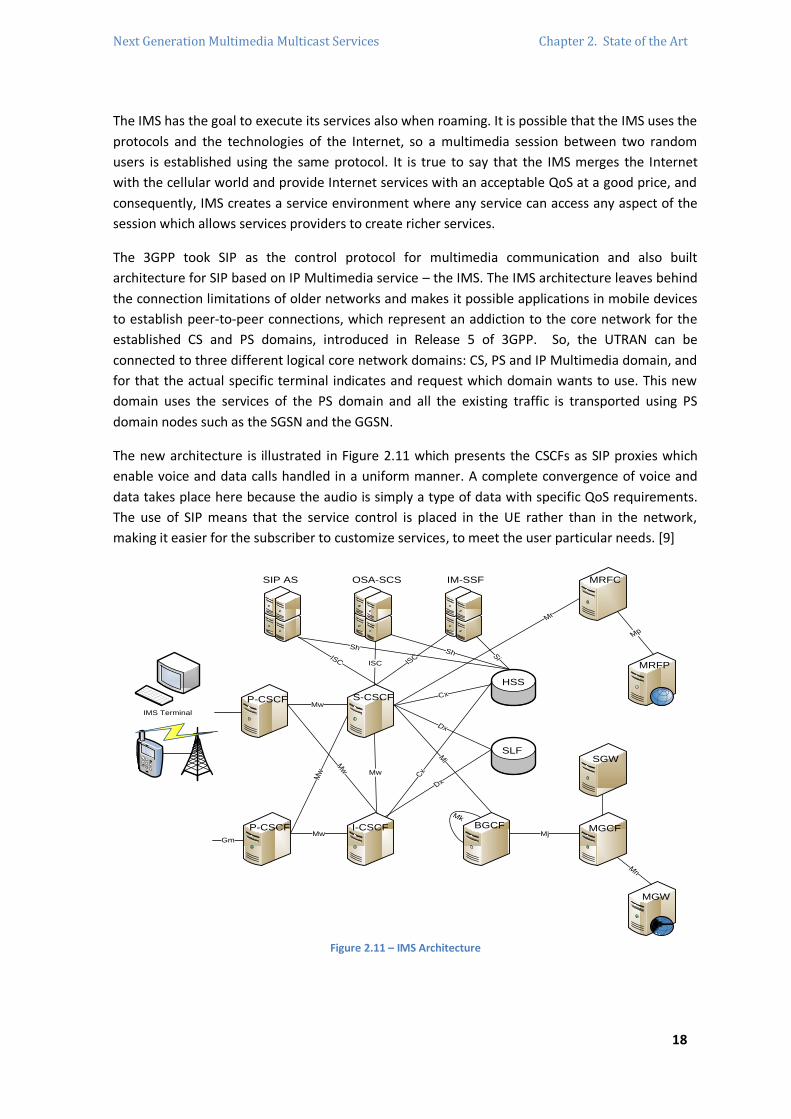
The 3GPP took SIP as the control protocol for multimedia communication and also built
architecture for SIP based on IP Multimedia service – the IMS. The IMS architecture leaves behind
the connection limitations of older networks and makes it possible applications in mobile devices
to establish peer-to-peer connections, which represent an addiction to the core network for the
established CS and PS domains, introduced in Release 5 of 3GPP. So, the UTRAN can be
connected to three different logical core network domains: CS, PS and IP Multimedia domain, and
for that the actual specific terminal indicates and request which domain wants to use. This new
domain uses the services of the PS domain and all the existing traffic is transported using PS
domain nodes such as the SGSN and the GGSN.
The new architecture is illustrated in Figure 2.11 which presents the CSCFs as SIP proxies which
enable voice and data calls handled in a uniform manner. A complete convergence of voice and
data takes place here because the audio is simply a type of data with specific QoS requirements.
The use of SIP means that the service control is placed in the UE rather than in the network,
making it easier for the subscriber to customize services, to meet the user particular needs. [9]
IMS Terminal
OSA-SCS
S-CSCF
P-CSCF
P-CSCF
I-CSCF
SIP AS IM-SSF
HSS
SLF
MRFC
SGW
MGCF BGCF
MRFP
MGW
Mr
Mi
Cx
Dx
Mj
Mp
Dx
Mw
Mw
Mw
Mw
Mw
Mk
Cx
ISC ISC
SiSh
Sh
ISC
Gm
Mn
Figure 2.11 – IMS Architecture

Next Generation Multimedia Multicast Services Chapter 2. State of the Art
19
2.4.2. IMS Concepts, Fundamentals and Requirements
The GSM CS network have two different planes: the signaling plane, including protocols used to
establish a CS path between terminals and service calling, and the media plane, which includes
the data transmitted over the CS path and the encoded voice between user terminals. In the
evolution to IMS, those paths become differentiated, which were triggered by the introduction of
services based on Intelligent Networks (IN). The GSM version of IN services is known as
Customized Application for Mobile networks using Enhanced Logic (CAMEL) services. The 3GPP,
besides the separation of the signaling and media planes, introduces split architecture for the
MSC: MSC Server (signaling plane) and MGW (media plane). The IMS keep the paths separated,
but this separation arrives to the point where the only nodes that need to handle signaling and
media are the IMS terminals and so no network node is needed to handle both planes.
The GPRS allowed users to connect to the Internet using native PS technologies and at the
beginning of the technology there were the Wireless Application Protocol (WAP) and the access
to corporate networks and public Internet as applications that made this technology go up. But,
anyway, there were not enough reasons to boost the PS mobile networks. The topics which the
IMS focused to deliver IP multimedia services to the users are described below.
Settlement of IP Multimedia Sessions – audio and video communications require the need for
the multimedia sessions over PS networks support. IMS users can mix and change IP based
services during a communication session as they want and when they want. The services have to
be available when a user moves from PS domain to the IMS domain.
IP Connectivity - the user device needs IP connectivity to access the IMS. The peer-to-peer
application needs end-to-end access and the connectivity is reachable with IPv4 or IPv6, and from
the home or visited network.
Engine able to acquire QoS for IP Multimedia Services – IMS will allow lost and out of order
packets. The IMS terminal is able to negotiate QoS parameters based on its own capabilities and
which are expressed during a SIP session setup.
IP Policy Control in Media Resources – ability to authorize and control the usage of traffic for IMS
media based on the signaling parameters at the IMS session, which requires interaction between
the IP Connectivity Access Network (IP-CAN) and the IMS. This control verifies the values that are
negotiated in SIP signaling when the bearers are activated for media traffic, it prevents the bearer
usage before the session establishment is finished and it starts and stops the traffic related to the
charging of a session. The policy control is able to receive notifications when the IP-CAN service is
modified, suspended or released. The protocol that IMS uses to transfer policy-related
information is the Common Open Policy Service (COPS) protocol and in both outsourcing and
provisioning models mixture17.
17 The COPS protocol is used between a Policy Decision Point (PDP) and a (Policy Enforcement Point) PEP to transmit policy related
information and has two models: the outsourcing when the PEP contacts the PDP every time a policy decision has to be made and the
PDP decides to communicate back. The configuration/provisioning model where the PDP configures the PEP with the policy to be used,
storing the policy received from the PDP locally using them to make decisions instead of contacting the PDP every time it needs.
Next Generation Multimedia Multicast Services Chapter 2. State of the Art
20
Interworking with the Internet and CS networks – it is an expected requirement because of
millions potential destinations and sources for multimedia sessions. The CS networks, such as
PSTN or others, needs to interwork with the IMS and for that an IMS terminal able to connect
with another terminal that is in a CS domain will be needed. So, the IMS supports communications
with PSTN, ISDN, mobile, Internet users and it supports sessions with Internet applications that
have been developed outside the 3GPP community.
Security – fundamental requirement which is divided into access security (authentication of users
and network, and protection of the traffic between the IMS terminal and the network) and into
network security (traffic protection between nodes that can belong to the same or different
operators). The IMS ensures that users are authenticated before they start to use the services.
Charging – the IMS architecture allows two charging models to be used in the same session.
Offline charging is for periodically services payments and online charging is used to charge
prepaid services. The network operator has the capability of correlating charging information
generated at transport. The IMS networks have to be able to exchange charging information with
other networks to apply in an ongoing session.
Roaming – users have to be able to access to their services wherever they are. The most normal
example is when a user goes to a different country where there is a roaming agreement signed.
The IMS roaming model refers to a network configuration which the visited network provides IP
connectivity.
Service Control – implemented for the delivered services by the operators to the users. It can be a
set of restrictions applicable to all users in the network and a set of policies which are made to
each user. The selected model to make this work is the home service control which means that
the entity that access to the subscriber database and interacts directly with service platforms is
always located at the user’s home network.
Quick creation of services – this requirement has a big impact on the design of the IMS
architecture and it says that IMS services do not need normalizations. Comparing it to the past,
when every single service needed some kind of normalization, it is a milestone in cellular design.
The delay caused is no longer applied and now the IMS reduces this delay by standardizing service
capabilities instead of services.
Access Independence – the support access for networks besides GPRS (multiple accesses) is
needed. The IMS is, in its essence, an IP network and so it is a lower layer and access-independent
network. The IMS signaling network and session management services are separated from the
transport and bearer services, so future services will run on top of the IMS signaling network. The
IMS was originally designed to be access-independent making IMS services provided over any IP
connectivity network. Logically, different services have different requirements: bandwidth,
latency and processing power in the device that is in use. This means that for different services
behave good, the network has to be equipped with access-aware control and service logic for
multimedia services. [10]

Next Generation Multimedia Multicast Services Chapter 2. State of the Art
21
2.4.3. IMS Architecture
The 3GPP does not normalize nodes but functions, so the IMS architecture is a gathering of
functions connected by normalized interfaces and it is possible that two functions can be
combined in a single node, or a single function can be divided in two or more nodes. This IMS
architecture is illustrated before in Figure 2.11 with the most important signaling interfaces. The
nodes illustrated belonging to the IP Multimedia Core Network Subsystem are defined in the
following sub-chapters.
2.4.3.1. HSS and SLF, the Databases
The Home Subscriber Server (HSS)18 is the central user information storage. The HSS is an
evolution of the GSM HLR database. This database is responsible for keeping all the users’
subscription data to make the existence of multimedia sessions possible. Those data can be about
the location, security (authentication and authorization), user profile (services subscribed) and the
Serving-CSCF (S-CSCF) allocated. The Subscriber Location Function (SLF) only exists where there
are more than one HSS in the network and it is a simple database keeping the information of the
HSS address. Both databases implement the Diameter protocol. [9]
2.4.3.2. CSCFs (Call/Session Control Functions)
A CSCF is a SIP server which processes SIP signaling in the IMS. It has an essential role in the IMS
and there are four types of CSCFs: Proxy-CSCF, Serving-CSCF, Interrogating-CSCF and Emergency-
CSCF. The description of each CSCF will be described further. The three first types all play a role
during registration, session establishment and SIP routing.
2.4.3.2.1. P-CSCF (Proxy-CSCF)
The P-CSCF is the first point of contact between the IMS terminal and the IMS network. It
processes SIP signaling and acts as an outbound/inbound SIP proxy server. It is also easy to verify
that when one IMS terminal is the destination or the source of some request, it will pass through
the P-CSCF and forward those SIP requests in the proper way. The P-CSCF is allocated to the IMS
terminal as long as the registration lasts, and it does not change in the meanwhile.
The P-CSCF has many functions, such as security related, which includes the authentication of the
user in the procedures. Then, the P-CSCF shares it to the other nodes of the network, so that it
does not need future authentications. During the registration and the negotiation of security
associations between the terminal and the P-CSCF, it is responsible for the confidential protection
and integrity of the SIP signaling. The P-CSCF is responsible for the verification of SIP requests by
the IMS terminals, forcing them to create these requests properly, according to the SIP rules. SIP
is a base-text protocol, so the SIP messages cannot be short and then the P-CSCF has a
mechanism of compressing and decompressing that is used to reduce the time to transmit that
message. In some cases, the P-CSCF has included a Policy Decision Function (PDF), that can also be
implemented alone, which manages QoS and authorizes resources in the media plane. The last
function to be noticed it is that P-CSCF generates charging information that will be sent to a node
responsible for collecting charging information.
18 If the number of users is too high for one single HSS, the network will have more than one HSS. To select the proper one is
mandatory to the network has a SLF. The HSS is implemented in a special way to avoid a point of failure.
Next Generation Multimedia Multicast Services Chapter 2. State of the Art
22
Usually, an IMS network includes several P-CSCFs for the sake of scalability and redundancy,
where each P-CSCF depending on the node capacity will serve a several number of IMS terminals.
The P-CSCF can be located in the visited network or in the home network of the user. In a normal
case, the user is attached to a GPRS network and then the P-CSCF is located in the same location
of the GGSN. [9]
2.4.3.2.2. I-CSCF (Interrogating-CSCF)
I-CSCF is a SIP proxy located in the edge of an administrative domain and whose address is listed
in the Domain Name System (DNS) records of the domain that belongs to. In a practical view,
when a SIP server needs to know which next SIP hop is to forward any message, the SIP server will
obtain the address of an I-CSCF for the destination domain. Due to this kind of SIP proxy server
procedure, the I-CSCF will interface with the HSS and the SLF offering user location information.
Another duty of the I-CSCF is to give to a user one S-CSCF, which is pick it up based on data
capabilities that arrives from the HSS and it is also responsible for routing SIP requests to the S-
CSCF or another application server.
The Diameter protocol is the protocol that those interfaces are based on. One optional function is
the possibility to encrypt parts of SIP messages that have critical information about the domain
which procedure is called Topology Hiding Inter-network Gateway (THIG) which is not used in all
networks. Also, like the P-CSCF and due the same reasons, a network will have a several number
of I-CSCFs that are normally located in the home network. [9]
2.4.3.2.3. S-CSCF (Serving-CSCF)
The S-CSCF is the central node of the signaling plane and besides being mainly a SIP server and
performing session control, it is also a SIP registrar that keeps a connection between the user
location (terminal IP address that the user is logged on) and the Public User Identity (SIP address
of record). The Diameter protocol is the interface implemented into the HSS. The S-CSCF needs to
download from the HSS the authentication vectors of the given user to perform the
authentication and also needs to download the user profile from the HSS and to inform the HSS
which S-CSCF is the one that is allocated to the user until the end of the registration process.
When the IMS terminal receives or sends SIP signaling, all of these signaling pass through the
allocated S-CSCF, which inspects all the SIP messages to be aware if has to visit some applications
servers that would provide that service to the user.
The S-CSCF provides SIP routing services19, establishment of policies on the operator where users
can be forbidden to establish some kind of session and keeps users from performing unauthorized
operations. When the S-CSCF receives requests from an originating user via P-CSCF, it needs to
decide, right away, which application servers are to be contacted and after this interaction the S-
CSCF can continue the session in the IMS or break to others domains. This behavior of routing
decisions of the S-CSCF is illustrated in Figure 2.12.
19 When a user dials up a telephone number instead of a SIP Uniform Resource Identifier (SIP URI), the S-CSCF provides translation
services based on DNS.

Next Generation Multimedia Multicast Services Chapter 2. State of the Art
23
Like the others CSCFs, there is a number of S-CSCF, for the same reasons, serving a limited
number of IMS terminals, whose location is always in the home network. The S-CSCF is able to
send accounting information to the charging system that is implemented in the network. [9] [10]
AS
P-CSCF P-CSCF
9
S-CSCF S-CSCF
2 8a
I-CSCF
64a
AS
3 - Maybe S-CSCF
contact AS
HSS
BGCF BGCF
4b. Maybe break
to CS
57 – Maybe S-CSCF
contact AS
8b – Maybe break
to CS
1
Figure 2.12 – S-CSCF routing
2.4.3.2.4. E-CSCF (Emergency-CSCF)
The E-CSCF is a functionality used only to handle IMS emergency requests, such as sessions
relayed for the police, the fire department and ambulance. The point is to select an emergency
center, such as the Public Safety Answering Point, where an emergency request should be
delivered. The choosing procedure is based on the user location or on the type of emergency and,
after the selection, the E-CSCF routes the request to the emergency center. The emergency calls
can be made even without the smart card inside the IMS terminal. [10]
2.4.3.3. Application Servers (AS)
The Application Servers are SIP entities that hosts and performs a set of innovate services. The
AS’s are not just simply entities, but functions on top of IMS adding value, providing new
multimedia services. Normally, there is more than one AS, each one specialized in particular
services implementing technologies20 and are located outside or in the home network. The AS
process an incoming SIP session from the IMS network creating SIP requests and sending
accounting information to the charging functions. SIP is the interface protocol between the AS
and the S-CSCF, but a different name was adopted for historical reasons as the IMS Service
Control (ISC). Figure 2.13 illustrates the possible combinations of Application Servers, as well as
the different interfaces between them and their relations.
20 These implemented technologies can be Java technology, SIP servlets or SIP Common Gateway Interface (CGI).
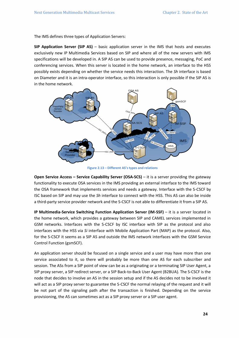
Next Generation Multimedia Multicast Services Chapter 2. State of the Art
24
The IMS defines three types of Application Servers:
SIP Application Server (SIP AS) – basic application server in the IMS that hosts and executes
exclusively new IP Multimedia Services based on SIP and where all of the new servers with IMS
specifications will be developed in. A SIP AS can be used to provide presence, messaging, PoC and
conferencing services. When this server is located in the home network, an interface to the HSS
possibly exists depending on whether the service needs this interaction. The Sh interface is based
on Diameter and it is an intra-operator interface, so this interaction is only possible if the SIP AS is
in the home network.
Third-Party
Service
Provider
Third-Party
Service
Provider
IMS
S-CSCFHSS
IM-SSF
OSA AS
gsmSCF
CAP
SIP AS
OSA-SCS
SIP ASSIP AS
SIP AS
ISC (SIP)
ISC (SIP)
ISC (SIP)
OSA APIs
ISC (SIP) ISC
(S
IP)
ISC (S
IP)
Si (MAP)
Sh (D
iameter)
Sh (Diameter)
Figure 2.13 – Different AS’s types and relations
Open Service Access – Service Capability Server (OSA-SCS) – it is a server providing the gateway
functionality to execute OSA services in the IMS providing an external interface to the IMS toward
the OSA framework that implements services and needs a gateway. Interface with the S-CSCF by
ISC based on SIP and may use the Sh interface to connect with the HSS. This AS can also be inside
a third-party service provider network and the S-CSCF is not able to differentiate it from a SIP AS.
IP Multimedia-Service Switching Function Application Server (IM-SSF) – it is a server located in
the home network, which provides a gateway between SIP and CAMEL services implemented in
GSM networks. Interfaces with the S-CSCF by ISC interface with SIP as the protocol and also
interfaces with the HSS via Si interface with Mobile Application Part (MAP) as the protocol. Also,
for the S-CSCF it seems as a SIP AS and outside the IMS network interfaces with the GSM Service
Control Function (gsmSCF).
An application server should be focused on a single service and a user may have more than one
service associated to it, so there will probably be more than one AS for each subscriber and
session. The ASs from a SIP point of view can be as a originating or a terminating SIP User Agent, a
SIP proxy server, a SIP redirect server, or a SIP Back-to-Back User Agent (B2BUA). The S-CSCF is the
node that decides to involve an AS in the session setup and if the AS decides not to be involved it
will act as a SIP proxy server to guarantee the S-CSCF the normal relaying of the request and it will
be not part of the signaling path after the transaction is finished. Depending on the service
provisioning, the AS can sometimes act as a SIP proxy server or a SIP user agent.

Next Generation Multimedia Multicast Services Chapter 2. State of the Art
25
2.4.3.3.1. AS – SIP User Agent
Figure 2.14 shows a session setup model where the AS is acting as the session destination whose
service is provided to the caller at the originating side. The P-CSCF is located in the home network.
The IMS terminal sends a SIP INVITE request to the originating P-CSCF and to the S-CSCF that
decides to forward to the AS. This AS works as a SIP UA and answers with a 200 – OK that passes
back through until the IMS terminal.
IMS Home Network
I-CSCF
S-CSCF
AS
1. INVITE
6. 200 OK
2. INVITE
5. 200 O
K
3. INVITE
4. 200 OK
P-CSCF
Service provided
to the callee
P-CSCF
S-CSCF
AS
1. INVITE
6. 200 OK
2. INVITE
5. 200 O
K
3. INVITE
4. 200 OK
Service provided
to the caller
IMS Home Network
Figure 2.14 – Terminating SIP UA providing services in
the originating leg
Figure 2.15 – Terminating SIP UA providing services in
the terminating leg
Figure 2.15 shows a different scenario where the AS is acting as a terminating SIP UA but the
service is provided to the terminating side. The AS takes the session and the user never receives
the SIP INVITE request. A user agent sends to the I-CSCF the INVITE request that is forwarded to
the S-CSCF and decides to send the request to an AS. The AS acts as a UA and establishes the
session answering the original user agent back with a 200 – OK response. A service that uses this
model of procedure is a service that needs a server to work the SIP request instead of the user,
which is used in the presence service where the proper server is specialized to treat this kind of
requests.
Other scenario, Figure 2.16, where the SIP AS acts as a caller that initiates the SIP session and the
service does not distinguish the originating from the terminating because the user receives the
session setup. An example of this possibility is the wake-up call service, where, at a given
moment, the AS initiates the session toward the IMS terminal to provide the service.
IMS Home Network
P-CSCF
S-CSCF
AS
3. INVITE
4. 200 OK
2. INVIT
E
5. 200 O
K
1. INVITE
6. 200 OK
Figure 2.16 – Application Server as originating SIP UA

Next Generation Multimedia Multicast Services Chapter 2. State of the Art
26
2.4.3.3.2. AS – SIP Proxy Server
The AS sometimes needs to act as a Proxy Server for the sake of the service that is providing, a
scenario showed in Figure 2.17. The IMS terminal sends a SIP INVITE request that traverses the P-
CSCF and the S-CSCF which decides to involve the AS sending the request to it. The S-CSCF inserts
proper information pointing to the AS and itself to allow the AS to send back the request. Other
information inserted will allow the S-CSCF to know that is the second time that it is receiving the
request and it will know that it has to send this request in the direction of the IMS terminal that
started the session.
IMS Home Network
I-CSCF
S-CSCF
AS
1. INVITE
12. 200 OK
2. INVITE
11. 200 O
K
3. INVITE
5. INVITE
4. INVITE
8. 200 OK P-CSCF 6. INVITE
7. 200 OK
9. 200 OK
10. 200 OK
IMS Home Network
P-CSCF
S-CSCF
AS
1. INVITE
10. 200 OK
2. INVITE
9. 200 O
K
3. INVITE 7. 200 OK
4. INVITE
5. I
NV
ITE
6. 2
00
OK
8. 200 OK
Figure 2.17 – SIP proxy server providing services in the originating side
Figure 2.18 – SIP proxy server providing services in the termination side
A configuration to provide a service to the callee, with the AS acting as a SIP proxy server is
showed in Figure 2.18. The INVITE request arrives to the I-CSCF, and then it is relayed to the S-
CSCF allocated to the user. The S-CSCF involves the AS that will provide the service and sends the
INVITE request to it. The AS executes the service and with some modifications in the header fields
of the SIP request, forward it back to the S-CSCF based on that information. The S-CSCF sends the
INVITE request to the IMS terminal making it pass through the P-CSCF allocated to the destination
user. The responses will pass back through the same path as before. This configuration can be
used in the call-forwarding service.
2.4.3.3.3. AS – SIP Redirect Server
Figure 2.19 shows an INVITE request arriving to the I-CSCF that is forwarded to the S-CSCF at the
home network. The S-CSCF decides to involve the AS and this one after receiving the request
generates a 302 – Moved Temporarily final response that has a contact header field that includes
the new contact URI. This response is forwarded back to the caller and will generate a new INVITE
request to the new destination that cannot be in the same IMS network. Basically, the SIP redirect
servers can be used in sessions that the operator are not interested in receiving a certain call
making it not to be part of the session. [9]
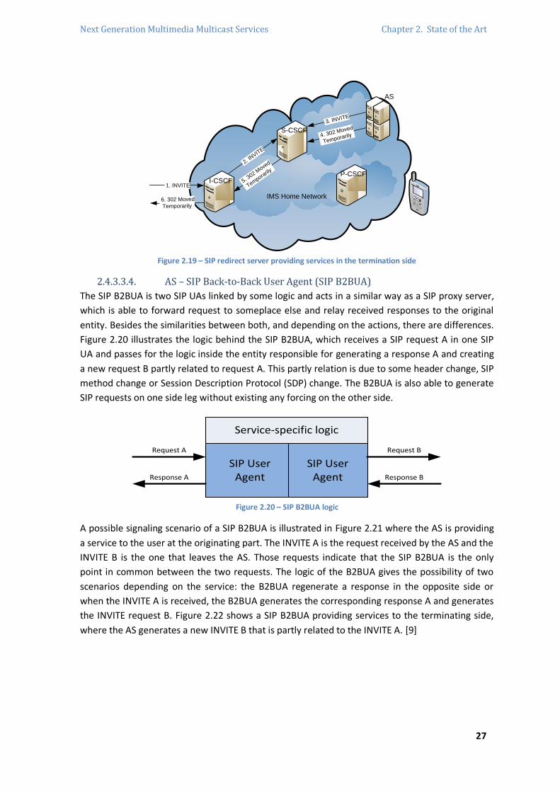
Next Generation Multimedia Multicast Services Chapter 2. State of the Art
27
IMS Home Network
I-CSCF
S-CSCF
AS
1. INVITE
6. 302 Moved
Temporarily
2. I
NVITE
5. 3
02 Move
d
Tempora
rily
3. INVITE
P-CSCF
4. 302 Moved
Temporarily
Figure 2.19 – SIP redirect server providing services in the termination side
2.4.3.3.4. AS – SIP Back-to-Back User Agent (SIP B2BUA)
The SIP B2BUA is two SIP UAs linked by some logic and acts in a similar way as a SIP proxy server,
which is able to forward request to someplace else and relay received responses to the original
entity. Besides the similarities between both, and depending on the actions, there are differences.
Figure 2.20 illustrates the logic behind the SIP B2BUA, which receives a SIP request A in one SIP
UA and passes for the logic inside the entity responsible for generating a response A and creating
a new request B partly related to request A. This partly relation is due to some header change, SIP
method change or Session Description Protocol (SDP) change. The B2BUA is also able to generate
SIP requests on one side leg without existing any forcing on the other side.
Service-specific logic
SIP UserAgent
SIP UserAgent
Request A
Response A
Request B
Response B
Figure 2.20 – SIP B2BUA logic
A possible signaling scenario of a SIP B2BUA is illustrated in Figure 2.21 where the AS is providing
a service to the user at the originating part. The INVITE A is the request received by the AS and the
INVITE B is the one that leaves the AS. Those requests indicate that the SIP B2BUA is the only
point in common between the two requests. The logic of the B2BUA gives the possibility of two
scenarios depending on the service: the B2BUA regenerate a response in the opposite side or
when the INVITE A is received, the B2BUA generates the corresponding response A and generates
the INVITE request B. Figure 2.22 shows a SIP B2BUA providing services to the terminating side,
where the AS generates a new INVITE B that is partly related to the INVITE A. [9]

Next Generation Multimedia Multicast Services Chapter 2. State of the Art
28
IMS Home Network
I-CSCF
S-CSCF
AS
1. INVITE A
12. 200 OK
2. INVITE A
11. 200 O
K
3. INVITE A
4. INVITE B
5. INVITE B 8. 200 OK
9. 200 OK
10. 200 OK
P-CSCF 6. INVITE B
7. 200OK
IMS Home Network
P-CSCF
S-CSCF
AS
1. INVITE A
10. 200 OK
2. INVITE A
9. 200 O
K
3. INVITE A
4. INVITE B
5. INVITE B 6. 200 OK
7. 200 OK
8. 200 OK
Figure 2.21 – SIP B2BUA providing services in the
origination side Figure 2.22 – SIP B2BUA providing services in the
termination side
2.4.3.3.5. Execution of a Service
Imagining a service provisioning, a given user sends an INVITE request routed to the S-CSCF which
evaluates all the criteria of the user service profile. The S-CSCF includes in the request the SIP URI
of the AS and its own S-CSCF SIP URI. The request is forwarded to the AS to provide the service,
which means to forward the request to the MRFC. The MRFC consults the request to find out
which announcement it has to play and sends back a 200 – OK response. The illustration of an
example for an execution of a service is in Figure 2.23.
IMS Home Network
I-CSCF
S-CSCF
AS
1. INVITE
10. 200 OK
2. INVIT
E
9. 200 O
K
3. INVITE
4. INVITE
5. INVITE 6. 200 OK
7. 200 OK
8. 200 OK
MRFC
MRFP
RTP
Figure 2.23 – Example of a service
2.4.3.4. MRF (Media Resource Function)
The MRF is always located in the home network and provides a source of media making it possible
to play announcements, mix media streams, conferencing, obtain statistics, a lot of media analysis
and bearer transcoding between different codecs in the IMS architecture. As it is illustrated in
Figure 2.23, the MRF is divided into the Media Resource Function Controller (MRFC) and the
Media Resource Function Processor (MRFP) that are for signaling and media plane, respectively.
The MRFC controls the resources in the MRFP with H.248 interface and handle SIP communication
to and from the S-CSCF, acting as SIP User Agent. The MRFP implements every function related to
media that is instructed by the MRFC with a low important role in IMS. [9]
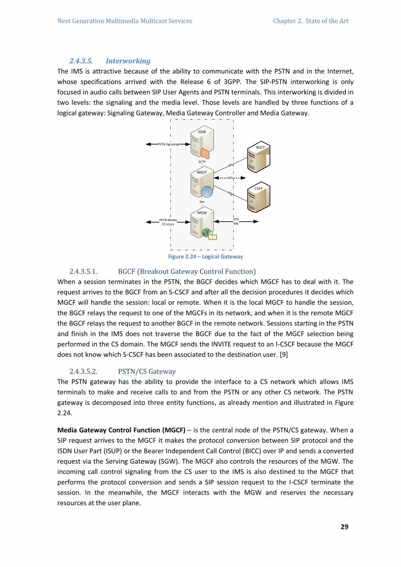
Next Generation Multimedia Multicast Services Chapter 2. State of the Art
29
2.4.3.5. Interworking
The IMS is attractive because of the ability to communicate with the PSTN and in the Internet,
whose specifications arrived with the Release 6 of 3GPP. The SIP-PSTN interworking is only
focused in audio calls between SIP User Agents and PSTN terminals. This interworking is divided in
two levels: the signaling and the media level. Those levels are handled by three functions of a
logical gateway: Signaling Gateway, Media Gateway Controller and Media Gateway.
PSTN Signaling
SIP
RTPMb
PSTN MediaCS Voice
SCTP
SGW
MGCF
MGW
Mn
BGCF
CSCF
Mj
Mg
Figure 2.24 – Logical Gateway
2.4.3.5.1. BGCF (Breakout Gateway Control Function)
When a session terminates in the PSTN, the BGCF decides which MGCF has to deal with it. The
request arrives to the BGCF from an S-CSCF and after all the decision procedures it decides which
MGCF will handle the session: local or remote. When it is the local MGCF to handle the session,
the BGCF relays the request to one of the MGCFs in its network, and when it is the remote MGCF
the BGCF relays the request to another BGCF in the remote network. Sessions starting in the PSTN
and finish in the IMS does not traverse the BGCF due to the fact of the MGCF selection being
performed in the CS domain. The MGCF sends the INVITE request to an I-CSCF because the MGCF
does not know which S-CSCF has been associated to the destination user. [9]
2.4.3.5.2. PSTN/CS Gateway
The PSTN gateway has the ability to provide the interface to a CS network which allows IMS
terminals to make and receive calls to and from the PSTN or any other CS network. The PSTN
gateway is decomposed into three entity functions, as already mention and illustrated in Figure
2.24.
Media Gateway Control Function (MGCF) – is the central node of the PSTN/CS gateway. When a
SIP request arrives to the MGCF it makes the protocol conversion between SIP protocol and the
ISDN User Part (ISUP) or the Bearer Independent Call Control (BICC) over IP and sends a converted
request via the Serving Gateway (SGW). The MGCF also controls the resources of the MGW. The
incoming call control signaling from the CS user to the IMS is also destined to the MGCF that
performs the protocol conversion and sends a SIP session request to the I-CSCF terminate the
session. In the meanwhile, the MGCF interacts with the MGW and reserves the necessary
resources at the user plane.
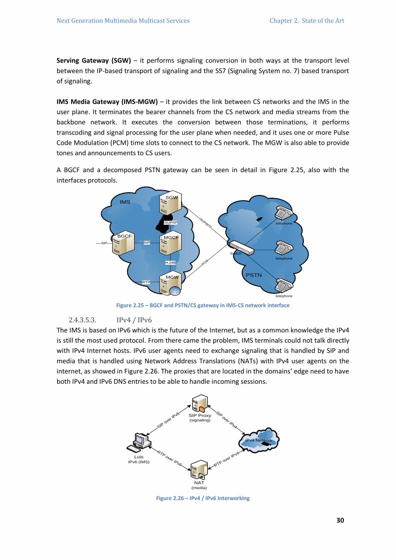
Next Generation Multimedia Multicast Services Chapter 2. State of the Art
30
Serving Gateway (SGW) – it performs signaling conversion in both ways at the transport level
between the IP-based transport of signaling and the SS7 (Signaling System no. 7) based transport
of signaling.
IMS Media Gateway (IMS-MGW) – it provides the link between CS networks and the IMS in the
user plane. It terminates the bearer channels from the CS network and media streams from the
backbone network. It executes the conversion between those terminations, it performs
transcoding and signal processing for the user plane when needed, and it uses one or more Pulse
Code Modulation (PCM) time slots to connect to the CS network. The MGW is also able to provide
tones and announcements to CS users.
A BGCF and a decomposed PSTN gateway can be seen in detail in Figure 2.25, also with the
interfaces protocols.
PSTN
IMS
BGCF MGCF
SGW
MGW
Switch
telephone
telephone
telephone
SIP
ISUP/IP
H.248
RTP
SIP
ISUP/MTP
PCM
Figure 2.25 – BGCF and PSTN/CS gateway in IMS-CS network interface
2.4.3.5.3. IPv4 / IPv6
The IMS is based on IPv6 which is the future of the Internet, but as a common knowledge the IPv4
is still the most used protocol. From there came the problem, IMS terminals could not talk directly
with IPv4 Internet hosts. IPv6 user agents need to exchange signaling that is handled by SIP and
media that is handled using Network Address Translations (NATs) with IPv4 user agents on the
internet, as showed in Figure 2.26. The proxies that are located in the domains’ edge need to have
both IPv4 and IPv6 DNS entries to be able to handle incoming sessions.
IPv4 Network
SIP Proxy(signaling)
Luis
IPv6 (IMS)
NAT
(media)
SIP o
ver I
Pv6SIP over IPv4
RTP over IPv4
RTP over IPv6
Figure 2.26 – IPv4 / IPv6 Interworking
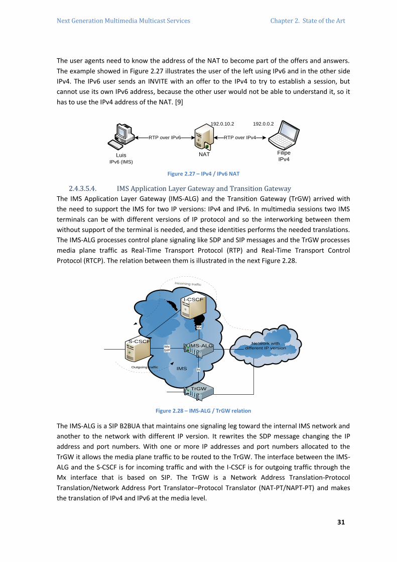
Next Generation Multimedia Multicast Services Chapter 2. State of the Art
31
The user agents need to know the address of the NAT to become part of the offers and answers.
The example showed in Figure 2.27 illustrates the user of the left using IPv6 and in the other side
IPv4. The IPv6 user sends an INVITE with an offer to the IPv4 to try to establish a session, but
cannot use its own IPv6 address, because the other user would not be able to understand it, so it
has to use the IPv4 address of the NAT. [9]
Luis
IPv6 (IMS)
NAT
RTP over IPv4RTP over IPv6
Filipe
IPv4
192.0.0.2192.0.10.2
Figure 2.27 – IPv4 / IPv6 NAT
2.4.3.5.4. IMS Application Layer Gateway and Transition Gateway
The IMS Application Layer Gateway (IMS-ALG) and the Transition Gateway (TrGW) arrived with
the need to support the IMS for two IP versions: IPv4 and IPv6. In multimedia sessions two IMS
terminals can be with different versions of IP protocol and so the interworking between them
without support of the terminal is needed, and these identities performs the needed translations.
The IMS-ALG processes control plane signaling like SDP and SIP messages and the TrGW processes
media plane traffic as Real-Time Transport Protocol (RTP) and Real-Time Transport Control
Protocol (RTCP). The relation between them is illustrated in the next Figure 2.28.
Network with
different IP version
IMS
S-CSCF
I-CSCF
IMS-ALG
TrGW
Mx
SIP
Mx
Ix
Incoming traffic
Outgoing traffic
Figure 2.28 – IMS-ALG / TrGW relation
The IMS-ALG is a SIP B2BUA that maintains one signaling leg toward the internal IMS network and
another to the network with different IP version. It rewrites the SDP message changing the IP
address and port numbers. With one or more IP addresses and port numbers allocated to the
TrGW it allows the media plane traffic to be routed to the TrGW. The interface between the IMS-
ALG and the S-CSCF is for incoming traffic and with the I-CSCF is for outgoing traffic through the
Mx interface that is based on SIP. The TrGW is a Network Address Translation-Protocol
Translation/Network Address Port Translator–Protocol Translator (NAT-PT/NAPT-PT) and makes
the translation of IPv4 and IPv6 at the media level.

Next Generation Multimedia Multicast Services Chapter 2. State of the Art
32
2.4.3.6. Home/Visited Networks
The home and visited network concept arrives from the GSM and GPRS, and all of the
mechanisms that are involved are reused by the IMS, with most of the IMS nodes located in the
home network. The exception is the P-CSCF that can be in both networks, which P-CSCF location
will be the same of the GGSN. This, of course, happens on roaming and the location of the S-CSCF
is always in the visited network. In Figure 2.29, the P-CSCF and the GGSN share the same network
and permits the P-CSCF to control the GGSN. This GGSN has to be an upgraded version to be
prepared to work with the IMS.
Home NetworkVisited Network
SGSN GGSN
P-CSCF
I-CSCF
S-CSCF
SIP AS
HSS
GPRS
Go
intra-operator
interface
Figure 2.29 – P-CSCF in the visited network
Figure 2.30 shows a configuration where both P-CSCF and GGSN are located in the home network.
Home NetworkVisited Network
SGSNGGSN
P-CSCF I-CSCF
S-CSCF
SIP AS
HSS
GPRS
Go
Figure 2.30 – P-CSCF and GGSN in the home network
In the previous illustrations, the comparison between the two scenarios is easy. The first one can
be seen as a vision on the future of the IMS, because requires IMS support from the visited
network. The second scenario is more real, where both P-CSCF and GGSN are located in the home
network and the visited network does not have to support mandatorily IMS, providing only the
radio bearers and the SGSN node. Being as the most common configuration used, it also has the
big disadvantage of all media plane being routed to the home network in the first place and only
after to the visited network, due to the fact that it has to pass through the GGSN, creating
undesired trombone effect that causes delays in the media plane. [9]

Next Generation Multimedia Multicast Services Chapter 2. State of the Art
33
2.4.4. SIP and other IMS Protocols
The Session Control Protocol chosen for the IMS was SIP, which establishes and manages
multimedia sessions over IP networks. The SIP protocol follows the client-server model, like many
protocols developed by the Internet Engineering Task Force (IETF) and it has the characteristics of
the Simple Mail Transfer Protocol (SMTP) and the Hypertext Transport Protocol (HTTP), which is
an important advantage, because these protocols are the most successful protocols on the
Internet. SIP is a single protocol which works end-to-end unlike BICC or H.32321, and makes the
creation of new services easier because is based in HTTP, making the SIP service developers able
to use all the service frameworks developed for HTTP.
The Authentication, Authorization and Accounting (AAA) protocol chosen for the IMS was an
evolution of the RADIUS protocol: the Diameter protocol. The Diameter is also used on the
Internet for AAA. An example is when a user dials up to an Internet Service Provider (ISP), the
network access server uses RADIUS to authenticate and authorize the user accessing the network.
Diameter consists on a base protocol that is complemented with Diameter Applications that are
customizations or extensions to Diameter to suit a particular application in a given environment.
IMS uses Diameter in a lot of interfaces but, but at the same time it does not use the same
Diameter application, like one for session setup and another for credit control accounting.
The other protocols used in IMS are: COPS protocol that is used to transfer policies between PDPs
and PEPs. H.248 is used by signaling nodes to control nodes in the media plane. RTP and RTCP are
used to transport real-time media. [9]
2.4.4.1. SIP (Session Initiation Protocol)
The main goal of SIP is to deliver a session description to a user at their current location. After the
knowledge of the location and the delivering of the initial description of the session22, SIP is able
to perform new session descriptions modifying the characteristics of an ongoing session and
terminates sessions at any moment depending on the user’s desire. These descriptions have to
follow a standard format to describe multimedia sessions: SDP.
SIP use the offer/answer model that is based on a two-way session description exchange and both
users will know the minimum information to establish the session. SIP identifies users using SIP
URIs that are similar to email addresses (a user name plus a domain name), and also reaches the
location of the user providing personal mobility at any moment. This is possible because SIP
introduces a new network element: Registrar. The Registrar of a particular domain handles
requests addressed to its domain. In a practical view, when a user logs on in a new location, it is
registered in the registrar of that domain. This means that the registrar will be able to forward all
the incoming requests to the user wherever the user is.
21 BICC and H.323 were the other two Session Control Protocols candidates for IMS. These two protocols differentiate, unlike SIP, the
User-to-Network Interface (UNI) from a Network-to-Network interface (NNI).
22 A session description contains information for the remote user to be able to join the session. This information includes IP addresses
and port numbers where the media needs to be sent and the codecs used to encode the voice and images of the participants.

Next Generation Multimedia Multicast Services Chapter 2. State of the Art
34
In the registration, the registrar in the new domain can store the mapping between user public
URI and the current location by using a local database or uploading this mapping into a location
server, and in this second case the registrar will need to consult it when it receives a request for
the user. This interface is based in another protocol than SIP. [9]
2.4.4.1.1. SIP Entities
Besides the Registrar entity introduced before, SIP defines more logical entities as described next.
All entities have its own function and are part of the SIP communication being as a client initiating
requests or as a server responding to the requests. The same logical entity can have both
functions.
User Agents (UAs) – are SIP endpoints that establish sessions with or without user intervention.
User Agents can be software running on a computer, SIP phones, laptops, PDAs and mobile
phones.
Proxy Servers – SIP routers receiving SIP messages from a UA or from any other proxy, relaying it
towards its destination. The functionality of the SIP routing starts when a user is available at more
than one user agent and it is registered in both locations on the registrar. When the registrar
receives a SIP message addressed to the user public URI, the registrar decides where to route it,
which decisions are based in a previously programming of the registrar and routes it accordingly.
This is important to implement services because is possible to deliver services based on any
criteria featured for the needs of each user, so a registrar routes SIP messages which is a proxy
characteristic leading to conclude that proxies and registrars are only logical roles that can be
inside the same physical box. Figure 2.31 and Figure 2.32 show the two different scenarios. In the
configuration of the separated roles the proxy needs to access the information of the user
location which is solved adding a location server that keeps the information the registrar uploads
and the proxy consults.
Registrar at
domain.com
SIP messa
ge
SIP message
Registrar at
domain.com
6. SIP message
3. SIP message
1. REGISTER
Location
Server
Proxy
2. Upload Location
Information
4. Where is Luis?5. Answer
Figure 2.31 – Registrar and Proxy at the same logical
level
Figure 2.32 – Registrar and Proxy as separate roles

Next Generation Multimedia Multicast Services Chapter 2. State of the Art
35
Forking Proxies – SIP proxy servers able to route messages to more than one destination, which is
very useful when receiving calls on several user agents at the same time is needed. A forking
proxy can route messages in parallel or in sequence. The parallel forking consists in the
simultaneous ringing of all the telephones in a house and the sequential forking consists of the
proxy trying the different locations one after the other. This procedure can be seen in Figure 2.33.
2. SIP
message
1. SIP message
sip:[email protected] Proxy
3. SIP message
Figure 2.33 – Forking proxy operation
Redirect Servers – used in SIP messages routing and instead of relaying the message, the redirect
server instruct the user agent or proxy to try another alternative addresses. This operation is
illustrated in Figure 2.34. [9]
1. SIP message
3. SIP message
Redirect Server
Try sip:[email protected]
Figure 2.34 – Redirect server operation
2.4.4.1.2. SIP Transactions
SIP is a textual request/response protocol based on HTTP. The SIP transaction consists of a
request from a client or on final responses from a server. The methods that are defined for SIP
messages are: ACK, BYE, CANCEL, INFO, INVITE, NOTIFY, OPTIONS, PRACK, PUBLISH, REGISTER,
SUBSCRIBE, UPDATE, MESSAGE and REFER. The responses are: 1xxProvisional, 2xxSuccess,
3xxRedirection, 4xxClient error, 5xxServer error and 6xxGlobal failure. There are three defined
types of SIP transactions:
Regular transactions – initiated by any request, besides INVITE, ACK or CANCEL. In a regular BYE
transaction, the user agent server receives the request from the proxy that received from the user
agent client. The user agent server generates a final response that terminates the transaction: 200
– OK. Before the final response can appear provisional responses.
INVITE-ACK transactions – involves two transactions: INVITE and ACK. Illustration in Figure 2.35,
the user agent server receives an INVITE request and generates provisional responses and a final
response. When the user agent client receives the final response, it generates an ACK request that
does not have any response associated.

Next Generation Multimedia Multicast Services Chapter 2. State of the Art
36
User Agent Client Proxy User Agent Server
1. INVITE
2. INVITE
3. 180 Ringing
4. 180 Ringing
5. 200 OK
6. 200 OK
7. ACK
Figure 2.35 – INVITE-ACK transaction
CANCEL Transactions – initiated by a CANCEL request which is always linked with a previous
transaction that has to be terminated. Cancel transactions are similar with regular transactions,
with the difference that the final response is generated by the proxy instead of the user agent
server. Figure 2.36 shows this transaction. [9]
User Agent Client Proxy User Agent Server
1. INVITE
2. INVITE
3. 180 Ringing
4. 180 Ringing
8. 200 OK
6. 200 OK
11. ACK
5. CANCEL
7. CANCEL
9. 487 Request Terminated
10. 487 Request Terminated
Figure 2.36 – CANCEL transaction
2.4.4.1.3. Session Establishment
To establish a multimedia session, the first step is to register the location of the user on the
Registrar of the domain. The user sends a REGISTER request to the Registrar with the information
of the current SIP contact and the Registrar responds saying that the transaction had success with
a 200 – OK response. In a later moment, another user invites the first one to establish an audio
session, illustrated in Figure 2.37, through a proxy server at the respective domain.

Next Generation Multimedia Multicast Services Chapter 2. State of the Art
37
Filipe SIP Proxy
Domain.com
1. INVITE sip:[email protected] SIP/2.0
Luis’s
Smart Phone
2. INVITE sip:[email protected] SIP/2.0 3. 200 OK
Contact: <sip:[email protected]> 4. 200 OK
Contact: <sip:[email protected]>
5. ACK sip:[email protected] SIP/2.0
Conversation
6. BYE sip:[email protected] SIP/2.0
7. 200 OK
Figure 2.37 – Session establishment through a SIP proxy.
The user in the left sends an INVITE request and the proxy relays it to the other user at its current
location. The user accepts and relays the message to the user in the left, which contains its
contact to allow the direct contact between them and after the ACK sent back, they can do what
they want. Changes are possible at a given moment by sending re-INVITEs, and to terminate the
session sending the BYE request directly and a response to it is needed. This procedure is a SIP
dialog and after the establishment of the session all the subsequent dialog follows the same path
of before. It is possible for the proxies to be maintained on the signaling path. [9]
2.4.4.1.4. Provisional Responses
SIP provisional responses are not transmitted reliably, because only the requests and the final
responses are considered important to be transmitted reliably. Because of this, SIP has to provide
the reliably for applications that need to ensure those responses to be delivered to the user agent
client. SIP always provides a message that confirms the reception of the original message by the
other end independently on the use of Transmission Control Protocol (TCP), User Datagram
Protocol (UDP) or Stream Control Transmission Protocol (SCTP) as the transport protocol. Because
of this, SIP can run over different access transports in the same dialog, which leads to situations
where the user agent can retransmit messages over a reliable transport protocol to avoid possible
losses in the leg that uses an unreliable transport protocol such as UDP.
There are SIP messages which are transmitted hop-by-hop like INVITE or others end-to-end
messages, such as the 200 – OK responses for an INVITE request. At the beginning flow of Figure
2.38, a hop-by-hop message is illustrated. After the reception of the 100 – Trying response, the
user agent client knows that the proxy has received the request. In the same Figure 2.38, the hop-
by-bop message is followed by an end-to-end message, where the user agent server, after the
reception of the ACK request, knows that the proxy and the user agent client have received the
response. [9]
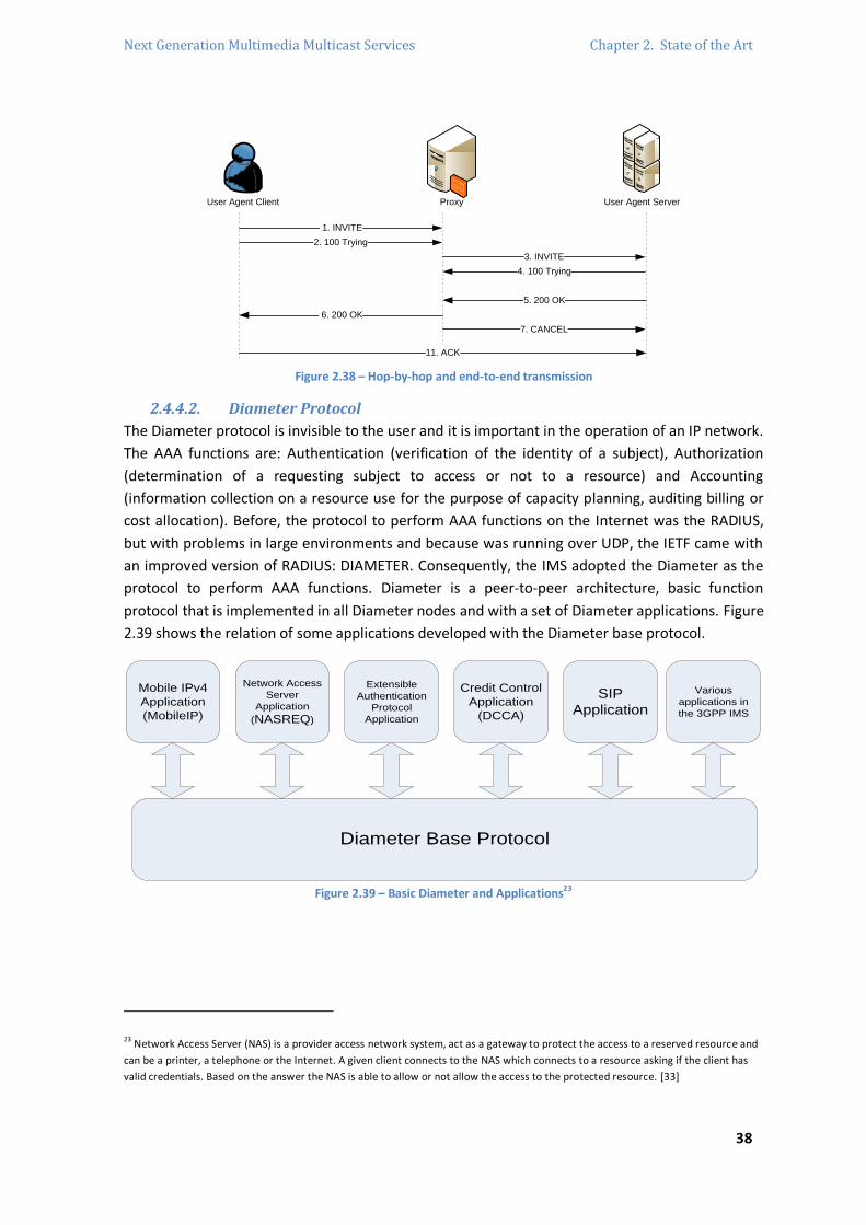
Next Generation Multimedia Multicast Services Chapter 2. State of the Art
38
User Agent Client Proxy User Agent Server
1. INVITE
2. 100 Trying
3. INVITE
4. 100 Trying
5. 200 OK
6. 200 OK
11. ACK
7. CANCEL
Figure 2.38 – Hop-by-hop and end-to-end transmission
2.4.4.2. Diameter Protocol
The Diameter protocol is invisible to the user and it is important in the operation of an IP network.
The AAA functions are: Authentication (verification of the identity of a subject), Authorization
(determination of a requesting subject to access or not to a resource) and Accounting
(information collection on a resource use for the purpose of capacity planning, auditing billing or
cost allocation). Before, the protocol to perform AAA functions on the Internet was the RADIUS,
but with problems in large environments and because was running over UDP, the IETF came with
an improved version of RADIUS: DIAMETER. Consequently, the IMS adopted the Diameter as the
protocol to perform AAA functions. Diameter is a peer-to-peer architecture, basic function
protocol that is implemented in all Diameter nodes and with a set of Diameter applications. Figure
2.39 shows the relation of some applications developed with the Diameter base protocol.
Diameter Base Protocol
Credit Control
Application
(DCCA)
Network Access
Server
Application
(NASREQ)
Mobile IPv4
Application
(MobileIP)
SIP
Application
Extensible
Authentication
Protocol
Application
Various
applications in
the 3GPP IMS
Figure 2.39 – Basic Diameter and Applications23
23 Network Access Server (NAS) is a provider access network system, act as a gateway to protect the access to a reserved resource and
can be a printer, a telephone or the Internet. A given client connects to the NAS which connects to a resource asking if the client has
valid credentials. Based on the answer the NAS is able to allow or not allow the access to the protected resource. [33]
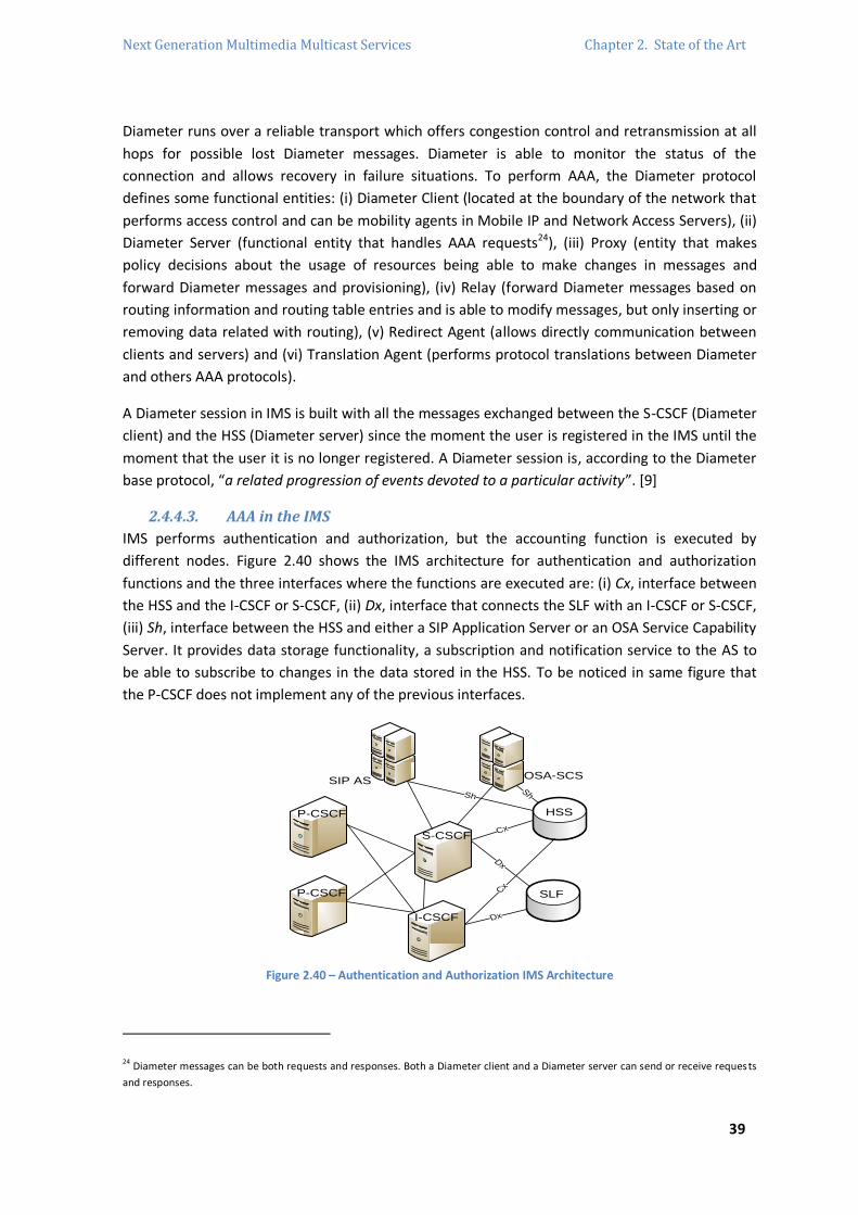
Next Generation Multimedia Multicast Services Chapter 2. State of the Art
39
Diameter runs over a reliable transport which offers congestion control and retransmission at all
hops for possible lost Diameter messages. Diameter is able to monitor the status of the
connection and allows recovery in failure situations. To perform AAA, the Diameter protocol
defines some functional entities: (i) Diameter Client (located at the boundary of the network that
performs access control and can be mobility agents in Mobile IP and Network Access Servers), (ii)
Diameter Server (functional entity that handles AAA requests24), (iii) Proxy (entity that makes
policy decisions about the usage of resources being able to make changes in messages and
forward Diameter messages and provisioning), (iv) Relay (forward Diameter messages based on
routing information and routing table entries and is able to modify messages, but only inserting or
removing data related with routing), (v) Redirect Agent (allows directly communication between
clients and servers) and (vi) Translation Agent (performs protocol translations between Diameter
and others AAA protocols).
A Diameter session in IMS is built with all the messages exchanged between the S-CSCF (Diameter
client) and the HSS (Diameter server) since the moment the user is registered in the IMS until the
moment that the user it is no longer registered. A Diameter session is, according to the Diameter
base protocol, “a related progression of events devoted to a particular activity”. [9]
2.4.4.3. AAA in the IMS
IMS performs authentication and authorization, but the accounting function is executed by
different nodes. Figure 2.40 shows the IMS architecture for authentication and authorization
functions and the three interfaces where the functions are executed are: (i) Cx, interface between
the HSS and the I-CSCF or S-CSCF, (ii) Dx, interface that connects the SLF with an I-CSCF or S-CSCF,
(iii) Sh, interface between the HSS and either a SIP Application Server or an OSA Service Capability
Server. It provides data storage functionality, a subscription and notification service to the AS to
be able to subscribe to changes in the data stored in the HSS. To be noticed in same figure that
the P-CSCF does not implement any of the previous interfaces.
OSA-SCS
S-CSCF
P-CSCF
P-CSCF
I-CSCF
SIP AS
HSS
SLF
ShSh
Cx
Dx
Dx
Cx
Figure 2.40 – Authentication and Authorization IMS Architecture
24 Diameter messages can be both requests and responses. Both a Diameter client and a Diameter server can send or receive requests
and responses.
Next Generation Multimedia Multicast Services Chapter 2. State of the Art
40
The difference between the Cx and the Dx interface is that the SLF acts with functions of a
Diameter redirect agent and the HSS acts as a Diameter server. The S-CSCF and the I-CSCF act as
Diameter Clients. These interfaces are used by the S-CSCF and the I-CSCF to perform functions for
a given user: discovery of the already allocated S-CSCF of a user, download of the authentication
vectors from the HSS, authorization of the roaming to a user, saving of the address of the new S-
CSCF allocated to a user, information about the registration state of a user to the HSS, download
from the HSS the user profile to future criteria, transferring of the user profile from the HSS to the
S-CSCF when profile changes happens and provision of I-CSCF with the information needed to
choose properly the S-CSCF.
The accounting function is based on data picking about the resource expenditure in order to
analyze trends, capacity and allocation price, auditory and billing. The charging is the aspect that
is of most interest and the IMS uses the Diameter protocol to transfer this information with the
purpose to charge, being the CSCF the responsible to inform the charging system about the type
and the length of the sessions. Charging systems use unique identifiers to correlate the
accounting data applied to a particular session received from different entities. [9]
2.4.5. IMS Identification
In IMS networks, as in every network, is mandatory to identify a user uniquely, with the goal of
every single call be correctly sent to the destination user. The identification can be made in a lot
of ways, such as in the PSTN where each user is identified by a group of numerical digits. Also,
services are identified by special numbers and IMS has this mechanism. Besides those, the IMS
has a deterministic way to identify users and the IMS user is identified with one or more Public
User Identities, such as SIP URI or TEL URI, which are attributed by the home operator and used to
route SIP signaling.
The Public User Identity is to IMS what the Mobile Station Integrated Services Digital Network
(MSISDN) is to GSM. The IMS brings a new concept: a set of implicitly registered public user
identities. In a normal SIP operation in IMS, each identity to be registered needs a SIP REGISTER
request, being possible to register many Public User Identities in one single message to save
resources.
Besides the Public User Identities, the subscribers have a Private User Identity and unlike being a
SIP URI or TEL URI will be a Network Access Identifier (NAI). Public User Identities are exclusively
for subscription identification and authentication matters. This identification is stored in the
smartcard, so the user is not aware of its existence and it has the same function of an
International Mobile Subscriber Identifier (IMSI) in GSM. One user has one Private User Identity
and can have more than one Public User Identity. The smartcard of the IMS terminal keeps the
Private and at least one Public User Identity and the HSS stores all the identification allocated to
the user creating a binding with the S-CSCF of the Public and the Private User Identities. After the
Release 6 of 3GPP, one IMS subscriber can have more than one Private User Identity and each one
have many Public User Identities, depending of the needs and desires of the IMS user. Also, the
Release 6 introduced the concept of Public Service Identities (PSIs) that is an identity allocated to
the service hosted in one Application Server.
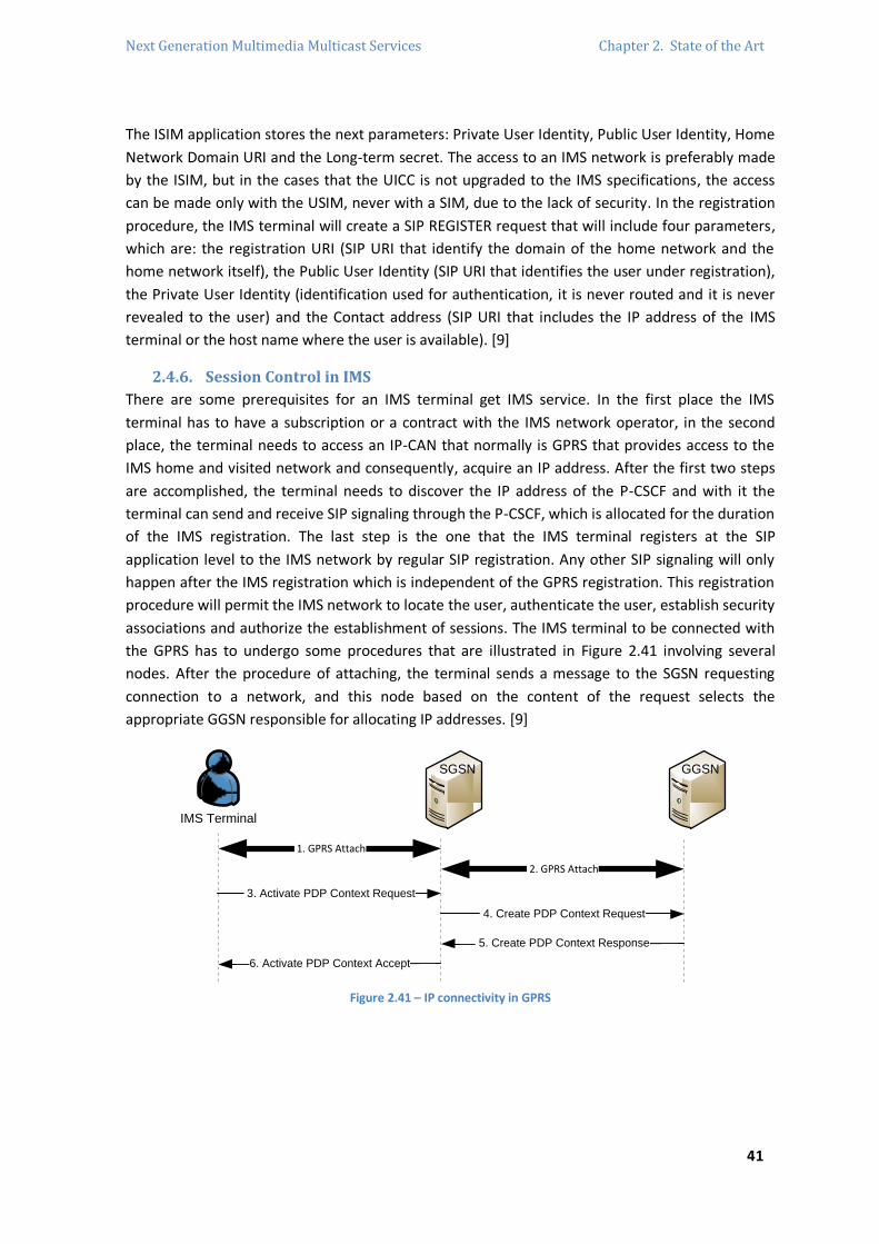
Next Generation Multimedia Multicast Services Chapter 2. State of the Art
41
The ISIM application stores the next parameters: Private User Identity, Public User Identity, Home
Network Domain URI and the Long-term secret. The access to an IMS network is preferably made
by the ISIM, but in the cases that the UICC is not upgraded to the IMS specifications, the access
can be made only with the USIM, never with a SIM, due to the lack of security. In the registration
procedure, the IMS terminal will create a SIP REGISTER request that will include four parameters,
which are: the registration URI (SIP URI that identify the domain of the home network and the
home network itself), the Public User Identity (SIP URI that identifies the user under registration),
the Private User Identity (identification used for authentication, it is never routed and it is never
revealed to the user) and the Contact address (SIP URI that includes the IP address of the IMS
terminal or the host name where the user is available). [9]
2.4.6. Session Control in IMS
There are some prerequisites for an IMS terminal get IMS service. In the first place the IMS
terminal has to have a subscription or a contract with the IMS network operator, in the second
place, the terminal needs to access an IP-CAN that normally is GPRS that provides access to the
IMS home and visited network and consequently, acquire an IP address. After the first two steps
are accomplished, the terminal needs to discover the IP address of the P-CSCF and with it the
terminal can send and receive SIP signaling through the P-CSCF, which is allocated for the duration
of the IMS registration. The last step is the one that the IMS terminal registers at the SIP
application level to the IMS network by regular SIP registration. Any other SIP signaling will only
happen after the IMS registration which is independent of the GPRS registration. This registration
procedure will permit the IMS network to locate the user, authenticate the user, establish security
associations and authorize the establishment of sessions. The IMS terminal to be connected with
the GPRS has to undergo some procedures that are illustrated in Figure 2.41 involving several
nodes. After the procedure of attaching, the terminal sends a message to the SGSN requesting
connection to a network, and this node based on the content of the request selects the
appropriate GGSN responsible for allocating IP addresses. [9]
IMS Terminal
3. Activate PDP Context Request
1. GPRS Attach
2. GPRS Attach
SGSN GGSN
4. Create PDP Context Request
5. Create PDP Context Response
6. Activate PDP Context Accept
Figure 2.41 – IP connectivity in GPRS
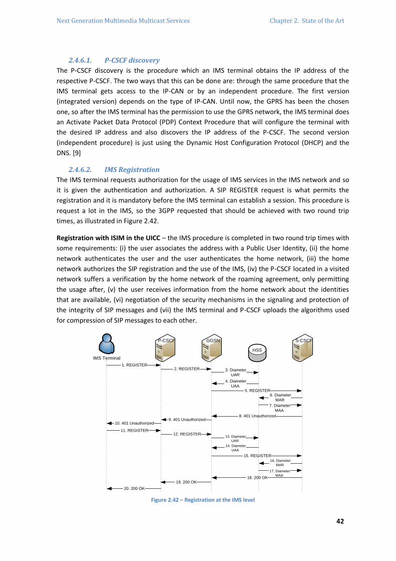
Next Generation Multimedia Multicast Services Chapter 2. State of the Art
42
2.4.6.1. P-CSCF discovery
The P-CSCF discovery is the procedure which an IMS terminal obtains the IP address of the
respective P-CSCF. The two ways that this can be done are: through the same procedure that the
IMS terminal gets access to the IP-CAN or by an independent procedure. The first version
(integrated version) depends on the type of IP-CAN. Until now, the GPRS has been the chosen
one, so after the IMS terminal has the permission to use the GPRS network, the IMS terminal does
an Activate Packet Data Protocol (PDP) Context Procedure that will configure the terminal with
the desired IP address and also discovers the IP address of the P-CSCF. The second version
(independent procedure) is just using the Dynamic Host Configuration Protocol (DHCP) and the
DNS. [9]
2.4.6.2. IMS Registration
The IMS terminal requests authorization for the usage of IMS services in the IMS network and so
it is given the authentication and authorization. A SIP REGISTER request is what permits the
registration and it is mandatory before the IMS terminal can establish a session. This procedure is
request a lot in the IMS, so the 3GPP requested that should be achieved with two round trip
times, as illustrated in Figure 2.42.
Registration with ISIM in the UICC – the IMS procedure is completed in two round trip times with
some requirements: (i) the user associates the address with a Public User Identity, (ii) the home
network authenticates the user and the user authenticates the home network, (iii) the home
network authorizes the SIP registration and the use of the IMS, (iv) the P-CSCF located in a visited
network suffers a verification by the home network of the roaming agreement, only permitting
the usage after, (v) the user receives information from the home network about the identities
that are available, (vi) negotiation of the security mechanisms in the signaling and protection of
the integrity of SIP messages and (vii) the IMS terminal and P-CSCF uploads the algorithms used
for compression of SIP messages to each other.
IMS Terminal
1. REGISTER
P-CSCF GGSN
2. REGISTER
HSS
3. Diameter
UAR
4. Diameter
UAA
S-CSCF
5. REGISTER 6. Diameter
MAR
7. Diameter
MAA
8. 401 Unauthorized 9. 401 Unauthorized
10. 401 Unauthorized
11. REGISTER 12. REGISTER
13. Diameter
UAR
14. Diameter
UAA
15. REGISTER 16. Diameter
MAR
17. Diameter
MAA 18. 200 OK
19. 200 OK
20. 200 OK
Figure 2.42 – Registration at the IMS level

Next Generation Multimedia Multicast Services Chapter 2. State of the Art
43
In Figure 2.42, the IMS terminal sends a SIP REGISTER to the P-CSCF which is located in the visited
network. The P-CSCF needs to locate the entry point to the home network, executing DNS
procedures which will provide the P-CSCF with the SIP-URI of an I-CSCF that should be located in
the entrance of the home network. At this moment, the I-CSCF does not know which S-CSCF is
allocated to the user and sends a Diameter User Authentication Request (UAR) to the HSS to
transfer the Public and Private User Identities and the visited network identifier that are extracted
from the SIP REGISTER. The HSS answers with a Diameter User Authentication Answer (UAA)
authorizing the user to roam the visited network and validates the Private associated to the Public
User Identity under registration. When the user does not have the S-CSCF allocated, the I-CSCF
chooses the S-CSCF based on specific capabilities. The S-CSCF receives the SIP REGISTER,
authenticating the user. This kind of request is the only one that is authenticated in the IMS. The
S-CSCF needs to contact the HSS to download the authentication data and to save the S-CSCF URI
for future queries to the HSS about the S-CSCF allocated. The HSS receives a Diameter Multimedia
Authentication Request (MAR) and after saving the data, it answers with a Multimedia
Authentication Answer (MAA) message with more than one authentication vector for the S-CSCF
properly authenticate the user.
Registration with USIM in the UICC - the user can be registered in the IMS network, but with
some problems involved. The initial problem is that the inability of the IMS terminal derives the
parameters needed to fill the SIP REGISTER. To solve the problem, the terminal extracts the IMSI
from the USIM to build a temporary Private and Public User Identity, and a home network domain
URI that allows it to build a SIP REGISTER request and route it to the home network. Because
those parameters are only used in the procedures of registration, re-registration, and when
eventually the user will be registered to the S-CSCF, it will send the regular Public User Identities.
The temporary identities are never known or used outside the home network, meaning that they
are only used during the session setup. [9]
2.4.6.3. Basic Session Setup
The process of establishing a basic session between two IMS terminals with no services associated
can appear a lot complicated, due to the several SIP messages involved, but it is the price of a very
rich protocol as SIP is. Both users are in a roaming situation, which leads to the observation of two
different visited networks in Figure 2.43. The users belong to different operators, so there are two
home networks, which mean that the P-CSCF will be in the visited network. The signaling plane
traverses a set of CSCFs and the media plane is sent end-to-end traversing only IP routers or
GGSNs. It is easy to see all signaling passing through both originating and terminating P-CSCF and
S-CSCF, which is a big difference in roaming, when compared to other cellular networks where the
signaling did not traverse the home network. The P-CSCF is mandatory in all the exchanged
signaling with the terminal, due to the compression and decompression procedure of SIP
messages in the interface with the terminal. All requests passes through the S-CSCF, allowing the
trigger of services that the user could be interested in, in the future, so this node plays an
important role by provisioning services, involving one or more application servers that implement
the service logic and is always located in the home network for the sake of availability of services
wherever the user is in the moment.
Next Generation Multimedia Multicast Services Chapter 2. State of the Art
44
The interaction of the I-CSCF with the HSS in the terminating network is to be noticed, because it
needs to know the address of the S-CSCF that serves the destination user. The HSS does not have
any other node that interacts within the home network, so the signaling path is asymmetric,
comparing both directions. Unlike the S-CSCF and the P-CSCF, the I-CSCF of the terminating
network cannot be in the path which means that the INVITE requests and its own responses will
arrive at the I-CSCF, but the other requests will not.
The INVITE request that the IMS terminal sends has the information of the IP address, port
number where the IMS terminal is supposed to receive the responses from the P-CSCF and the
transport protocol. When the INVITE request is ready and completed the terminal sends it to its
own P-CSCF. The P-CSCF verifies that the IMS terminal is acting in the correct way according to the
IMS routing requirements, such as the mandatory S-CSCF traversing as the next SIP hop, the
inspection of the SDP offer, insertion of charging headers and the applying of SIP compression.
The S-CSCF allocated to the caller user receives the INVITE request and examines from where this
request came, because the user profile which has, among other information, the filter criteria that
will determine if it is to trigger the AS to provide a service to the user was downloaded in the
registration.
The S-CSCF is the first node that tries to route the SIP request based on the destination of the
session, unlike the P-CSCF that just takes care of next node. Before the S-CSCF relay the request
has learnt the information to build the INVITE request to send it to the right I-CSCF at the
terminating home network discovered by DNS procedures. The I-CSCF receives the request and it
is only interested in the destination, so it has to forward the SIP request to the S-CSCF allocated to
the callee. To be aware of the address, the I-CSCF sends a Diameter Location Info Request (LIR)
message querying the HSS for the address that the S-CSCF has saved. The I-CSCF will forward the
request when it receives a Diameter Location Info Answer (LIA) message with the address
pretended from the HSS.
The S-CSCF in the terminating home network identifies the user and evaluates the filter criteria of
the called user. The INVITE request has to go to the designated IMS terminal so the P-CSCF that is
assigned to the user, whose address was learnt during registration, has to be passed through. The
terminating P-CSCF extracts the Public User Identity from the SIP INVITE request to find the
proper security associations and will always remain in the future path. The P-CSCF will do
functions related to charging, security, control of the GGSN, compression of SIP signaling and be a
SIP proxy. The IMS terminal has to be able to generate the answer automatically after receiving it,
without the hand of the user, which is the provisional 183 – Response that will traverse the same
proxies of the INVITE.
The IMS terminal processes the 183 – Response, interested in the destination IP address where
the media streams will be sent. The 183 – Response requires the creation of a PRACK request that
will traverse all the proxies besides the I-CSCF that it is not in the path and, at the same time, the
IMS terminal starts the mechanism of reservation of resources. The callee receives and generates
a 200 – OK answer and also reserves resources that involve the SGSN, the GGSN and the radio
nodes.

Next Generation Multimedia Multicast Services Chapter 2. State of the Art
45
IMS Terminal
1 1. INVITE
P-CSCF
HSS
2. 100 Trying
S-CSCF
3. INVITE
4. 100 Trying 5. INVITE
I-CSCF
6. 100 Trying 7. Diameter LIR
8. Diameter LIA 9. INVITE
S-CSCF
10. 100 Trying
P-CSCF
11. INVITE
12. 100 Trying 13. INVITE
IMS Terminal
2
14. 100 Trying
15. 183 Session
Progress 16. 183 Session
Progress 17. 183 Session
Progress 18. 183 Session
Progress 19. 183 Session
Progress 20. 183 Session
Progress
21. PRACK 22. PRACK
23. PRACK 24. PRACK
25. PRACK
26. 200 OK
27. 200 OK 28. 200 OK
29. 200 OK
30. 200 OK
31. UPDATE 32. UPDATE
33. UPDATE 34. UPDATE
35. UPDATE
36. 200 OK 37. 200 OK
38. 200 OK 39. 200 OK
40. 200 OK
Pre-Alert
User
Alert
User
41. 180 Ringing
42. 180 Ringing 43. 180 Ringing
44. 180 Ringing 45. 180 Ringing
46. 180 Ringing
47. PRACK 48. PRACK
49. PRACK 50. PRACK
51. PRACK
52. 200 OK 53. 200 OK
54. 200 OK
55. 200 OK 56. 200 OK
Accept
Session 57. 200 OK
58. 200 OK 59. 200 OK
60. 200 OK 61. 200 OK
62. 200 OK
63. ACK 64. ACK
65. ACK
66. ACK 67. ACK
Media Plane
Criteria
evalutation
Re
so
urc
e R
ese
rva
tio
nR
eso
urc
e R
ese
rva
tion
Criteria
evalutation
Terminating Home Network
Terminating
Visited
Network
Origininating
Home
Network
Originating
Visited
Network
Figure 2.43 – Session Setup without services provisioning
The procedure of alerting the callee can only be made after the reservation has been completed
and when the callee’s terminal has total information about the completed reservation of
resources in the side of the caller. When the callee’s terminal rings, it will generate a provisional
response 180 – Ringing and when the callee finally accepts the session, the IMS terminal sends a
200 – OK response, completing the INVITE transaction and after the caller receives it, it will start
to generate the media plane traffic. [9]

Next Generation Multimedia Multicast Services Chapter 2. State of the Art
46
2.5. MBMS (Multimedia Broadcast Multicast Service)
2.5.1. Introduction
The MBMS is a sub-system that started to be standardized in the Release 6 of the 3GPP. The
fundamental point of the MBMS is the data transmission from a single source to multiple
recipients with specified QoS, which allows network resources to be shared, meaning that MBMS
is a point-multipoint service. The MBMS offers two modes of transmissions: Multicast and
Broadcast mode.
On the control plane the MBMS manages the bearer service activation status of the UE,
introduces a new entity Broadcast Multicast – Service Center (BM-SC) responsible for the
management of the broadcast and multicast content that arrives into the UMTS network, allows
control of the initiation and termination of a session by the MBMS user service and also manage
bearer resources for the distribution of MBMS data. The key in MBMS is the IP which is used to
manage all MBMS multicast services. [11] [12]
2.5.2. MBMS Architecture
The introduction of MBMS is carried by the addition of new capabilities for the already existed
functional entities and adding new functional entities: BM-SC which provides functionalities for
the provision and delivery of MBMS user services. MBMS new architecture enables the efficient
usage of radio and core network resources especially for the efficiency of the radio interface.
The MBMS architecture is represented in the Figure 2.44 with enhanced PS domain entities to
provide the MBMS bearer service. The GGSN is the entry point of IP multicast traffic as MBMS
data and with a notification from the BM-SC, it is also responsible for correct provisioning of the
radio resources for the MBMS transmission inside the UTRAN/GERAN. The SGSN have the
capacity to hold a user-specific MBMS context for each activated multicast MBMS bearer service
and also has to support mobility. In the multicast mode the mechanisms for managing the MBMS
bearer service activation status of UEs and outsourcing authorization decisions to the MBMS user
service and also in the broadcast mode the provisioning control of session initiation, modification
and termination by the MBMS user service and managing bearer resources for the distribution of
MBMS data are provided. [13] [11]
GERAN
UTRAN
UE
BM-SCGGSNSGSN
HLR
UE
Uu
Um
Iu
Gr
Gn/Gp
Gmb
Gi
Content Provider/Multicast Broadcast Source
PDN(Internet)
Iu/G
b
Content Provider/Multicast Broadcast Source
BM-SC
Gi
Mz
Other PLMN
Figure 2.44 – MBMS Reference Architecture
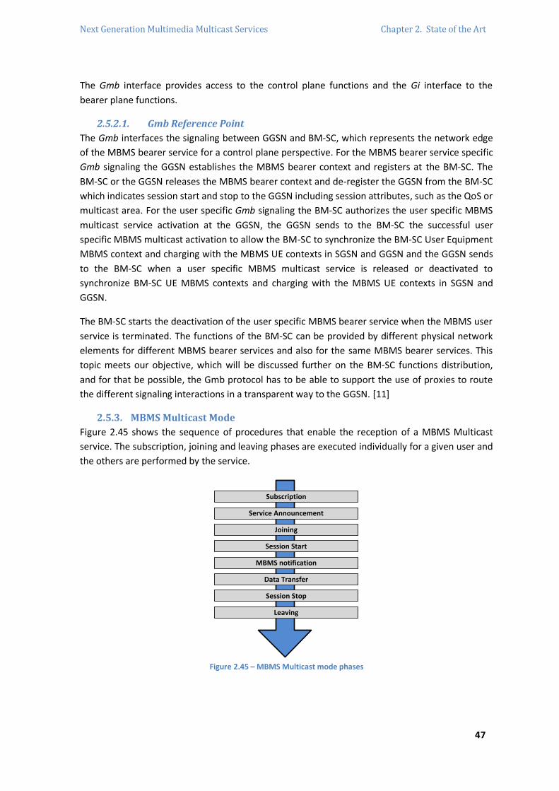
Next Generation Multimedia Multicast Services Chapter 2. State of the Art
47
The Gmb interface provides access to the control plane functions and the Gi interface to the
bearer plane functions.
2.5.2.1. Gmb Reference Point
The Gmb interfaces the signaling between GGSN and BM-SC, which represents the network edge
of the MBMS bearer service for a control plane perspective. For the MBMS bearer service specific
Gmb signaling the GGSN establishes the MBMS bearer context and registers at the BM-SC. The
BM-SC or the GGSN releases the MBMS bearer context and de-register the GGSN from the BM-SC
which indicates session start and stop to the GGSN including session attributes, such as the QoS or
multicast area. For the user specific Gmb signaling the BM-SC authorizes the user specific MBMS
multicast service activation at the GGSN, the GGSN sends to the BM-SC the successful user
specific MBMS multicast activation to allow the BM-SC to synchronize the BM-SC User Equipment
MBMS context and charging with the MBMS UE contexts in SGSN and GGSN and the GGSN sends
to the BM-SC when a user specific MBMS multicast service is released or deactivated to
synchronize BM-SC UE MBMS contexts and charging with the MBMS UE contexts in SGSN and
GGSN.
The BM-SC starts the deactivation of the user specific MBMS bearer service when the MBMS user
service is terminated. The functions of the BM-SC can be provided by different physical network
elements for different MBMS bearer services and also for the same MBMS bearer services. This
topic meets our objective, which will be discussed further on the BM-SC functions distribution,
and for that be possible, the Gmb protocol has to be able to support the use of proxies to route
the different signaling interactions in a transparent way to the GGSN. [11]
2.5.3. MBMS Multicast Mode
Figure 2.45 shows the sequence of procedures that enable the reception of a MBMS Multicast
service. The subscription, joining and leaving phases are executed individually for a given user and
the others are performed by the service.
Subscription
Service Announcement
Joining
Session Start
MBMS notification
Data Transfer
Session Stop
Leaving
Figure 2.45 – MBMS Multicast mode phases

Next Generation Multimedia Multicast Services Chapter 2. State of the Art
48
The MBMS multicast mode works in a complex way compared with the broadcast mode and
considers high level mechanisms for subscription management, in order to optimize the
distribution. The description of the needed MBMS multicast phases is below.
Subscription – it is the first phase of the multicast mode and it establishes the connection
between the user and the service provider which makes it possible for the user to receive the
related MBMS multicast service. The subscription information is saved at the BM-SC.
Service Announcement – it can be called also as discovery mechanism and it allows the user to
request or to be notified about the several MBMS user services available. It is used to give to the
user information about the service, such as parameters required for the service activation. The
announcement mechanisms are: (i) Short Messaging Service (SMS) Cell Broadcast to advertise
MBMS Multicast and Broadcast user services, (ii) MBMS Broadcast mode to advertise MBMS
Multicast and Broadcast user Services, (iii) MBMS Multicast mode to advertise MBMS Multicast
user Services, (iv) PUSH technology25 such as WAP, Short Message Service – Point to Point (SMS-
PP) and MMS, and (v) Uniform Resource Locator (URL) such as HTTP and File Transfer Protocol
(FTP). To inform the users about MBMS services, the chosen method has to be care about the
location of the users and about the ones that are not subscribed to a MBMS service, who should
also be able to discover MBMS services.
Joining – user MBMS multicast activation. It is the process when the user becomes a member of
the multicast group. The user indicates to the network that wants to receive Multicast mode data
of a specific service.
Session Start – the BM-SC is ready to send data and can be identified with the start of the
“Multicast Session”. Session Start is service independent activation by the user, where the user
can activate the service before or after the Session Start. This phase is the trigger for network
resources establishment for MBMS data transfer.
MBMS Notification – reports to the UEs about the forthcoming and ongoing multicast data
transfer.
Data Transfer – UEs receive the transferred data. The arrival of the first packet to the GGSN could
be at the same time of the Session Start.
Session Stop – the BM-SC knows that there is no more data to be delivered for some time and if
this period of time is too long, the network resources are released.
Leaving – the user deactivate the MBMS multicast. It is the process which a subscriber leaves a
multicast group indicating no more Multicast data to receive from that specific service. [11]
25 PUSH mechanism is an Internet based communication style where the request for a transaction is started from the central server. It
is the opposite of the PULL mechanism where the request for communication is initiated by the user client or receiver.

Next Generation Multimedia Multicast Services Chapter 2. State of the Art
49
The sequence of phases could be repeated depending of the need to transfer data. The
Subscription, Joining and Leaving phases and also the Service Announcement and MBMS
Notification can run in parallel with other phases. [13] [11]
2.5.4. MBMS Broadcast Mode
The broadcast mode is provisioned in a simple way since it does not involve user subscriptions.
The phases needed to make it happen are showed in the Figure 2.46. The normal procedure is the
repeating of the following phases’ sequence, depending on the needing data. The service
announcement and the MBMS notification can run parallel to other phases with the objective of
inform the UEs which did not receive the related service. The phases of MBMS broadcast service
provision are presented below.
Service Announcement
Session Start
MBMS notification
Data Transfer
Session Stop
Figure 2.46 – Broadcast mode phases
Service Announcement – informs the UEs about the forthcoming services and has the same
definition of the MBMS Multicast service announcement.
Session Start – the BM-SC is ready to send data. It is identified with the start of a “Broadcast
Session” and it is the trigger point for the bearer resource establishment for MBMS data transfer.
MBMS notification – reports to the UEs about the forthcoming and ongoing multicast data
transfer.
Data Transfer – MBMS data is transferred to the UEs.
Session Stop – it is the last sequence point of the MBMS Broadcast Mode. The MBMS application
decides if it continues to transfer MBMS data for a period of time and, if it takes too long, the
bearer resources associated to the service is removed and the network resources are released.
There is an extra phase that is used to update an ongoing MBMS Broadcast session: Session
Update. The parameters that can be updated are the MBMS Service Area and the list of SGSNs
only from BM-SC. The main characteristic of this mode is that any user present will receive the
broadcast data. [13]

Next Generation Multimedia Multicast Services Chapter 2. State of the Art
50
2.5.5. BM-SC (Broadcast Multicast – Service Center)
The BM-SC is the new functional entity introduced in Release 6 and provides functions for MBMS
user service provisioning and delivery. It can be considered the entering point for the MBMS
transmissions from the content provider, used for the authorization and initiation of the MBMS
bearer service within the PLMN and it can also be in charge for the scheduling and delivery of
MBMS transmissions. The BM-SC is a functional entity which has to exist for each MBMS user
service. The BM-SC functions are described below. [13]
2.5.5.1. Membership Function
The BM-SC has the function of allowing authorization for the users which request the activation
for a MBMS service. The Membership function has subscription data of MBMS service users and
generates charging information for MBMS service users. This function belongs to the service level
with the possibility to provide user level function as well. [13]
2.5.5.2. Session and Transmission Function
The first matter of this function is the ability to schedule MBMS session transmission, MBMS
session re-transmissions and it gives an MBMS Session Identifier to each MBMS session, in order
to allow the UE to distinguish the MBMS session retransmissions. The BM-SC has the capacity to
provide the GGSN with transport associated parameters, such as QoS and multicast/broadcast
area and to initiate and terminate MBMS transport resources prior to and following transmission
of MBMS data. The BM-SC Session and Transmission Function shall be able to include
synchronization information for the MBMS payload when IP multicast is used for distribution from
the GGSN to RNC. Also, the authentication and authorization of the external sources and
acceptance of their content has to be performed by this function.
2.5.5.3. Proxy and Transport Function
This function is an MBMS bearer service function and it is able to handle the BM-SC providing
functions for different MBMS services by multiple physical network elements. It generates
charging records for content provider charging of transmitted data, acts as a middleware device
for the MBMS data sent from the BM-SC Session and Transmission function.
2.5.5.4. Service Announcement Function
The BM-SC provides service announcements for multicast and broadcast MBMS user service,
provides user media description, MBMS session descriptions to the user media descriptions. The
function is a user service level function and supports some announcement mechanisms whose
services are triggered by the BM-SC, but are not mandatory sent, by the BM-SC. [13]
2.5.6. Other Entities for MBMS support
2.5.6.1. UE (User Equipment)
The UE support functions for the activation and deactivation of the MBMS service and security
functions appropriated for MBMS. With one MBMS service activated, no more user requests is
necessary to receive MBMS data, but the user can be notified when the data transfer is about to
start.

Next Generation Multimedia Multicast Services Chapter 2. State of the Art
51
The User Equipment, and considering the capacity of the terminal, has to be able to keep MBMS
data, receive MBMS service announcements, paging information and to support simultaneous
services. The notification sent to the UE with the MBMS Session Identifier serves to the UE to
decide if it is to ignore the forthcoming transmission of MBMS session. [13]
2.5.6.2. UTRAN/GERAN
The UTRAN/GERAN is responsible the efficient delivery of the MBMS data to the designated
multicast or broadcast service area. The efficient delivery of MBMS data in multicast mode
requires proper mechanisms in the UTRAN/GERAN. An example can be when it is to choose the
appropriate radio bearer depending on the number of users in a cell before and during and MBMS
transmission.
The MBMS transmissions may be initiated and terminated constantly and the UTRAN/GERAN has
to support these initiations and terminations by the CN, and later it has to be able to support the
reception of MBMS data from the CN over the interfaces Iu shared by the UEs. In the MBMS
applications mobility is expected, so the handle with the possibility of data loss caused by this
mobility of the UE has to be guaranteed. This functional entity shall be able to transmit MBMS
service announcements, paging information and support other parallel services with MBMS. [13]
2.5.6.3. SGSN (Serving GPRS Support Node)
The SGSN in the MBMS architecture has the role to performing user individual network control
function and to generate the MBMS transmissions to RAN/GERAN. The SGSN has to be able to
provide support mobility procedures for intra and inter SGSNs. This kind of procedures requires
that the SGSN store a user specific MBMS context for each activated multicast service and to pass
these contexts to the new SGSN during the inter-SGSN mobility procedures. The SGSN is also
responsible for creating charging data for each user and after the SGSN it has to provide functions
to support the charging of prepaid users.
The SGSN establish Iu and Gn interfaces which the user can share when the data has to be
transferred and it is done after the notification received from the GGSN. When the data is no
longer available, the SGSN is able to pull down those bearers after a notification from the GGSN.
2.5.6.4. GGSN (Gateway GPRS Support Node)
The GGSN has the role of serving as the entry point for IP multicast traffic as MBMS data. After
the notification from BM-SC, the establishment for a broadcast or multicast MBMS transmission
at the level of the user is needed and the GGSN has to be able to do it. The establishments for
multicast services are performed by those SGSNs that have requested before to receive
transmissions for the specific multicast service. Afterwards, and after BM-SC notification, the
GGSN have to pull down the established user plane.
The GGSN has to be able to receive IP multicast traffic, from the BM-SC or from another source of
data. The GGSN also has other functions at the MBMS service, but they are not exclusive to
MBMS: Message Screening, Charging Data Collection and QoS negotiation. [13]

Next Generation Multimedia Multicast Services Chapter 2. State of the Art
52
2.5.7. MBMS Attributes and Parameters
2.5.7.1. MBMS UE Context
The MBMS UE Context is used in the multicast mode and it is specific UE information created
when the UE join an MBMS bearer. It is originated in the UE, SGSN, GGSN and BM-SC. There is one
MBMS UE Context for one MBMS bearer that the UE has joined. The parameters of the MBMS UE
Context are: (i) IP multicast address, (ii) Access Point Name (APN) where the IP multicast address
is defined, (iii) Temporary Mobile Group Identity (TMGI)26 allocated to the MBMS bearer and (iv)
Linked Netscape Server Application Programming Interface (NSAPI) which is the NSAPI of the PDP
context used by the UE to carry Internet Group Management Protocol (IGMP)/Multicast Listener
Discovery (MLD).
2.5.7.2. MBMS Bearer Context
It is referred to as MBMS Service Context in RAN, which has all the information to describe a
particular bearer of a MBMS service and it is created in each point implicated in the delivery of
MBMS data. The MBMS Bearer Context is created in the SGSN and GGSN at the time of creation
of the first MBMS UE Context in the node or when a downstream node requests it and is
configured in the BM-SC. The MBMS Bearer Context is created in the SRNC when a first MBMS UE
Context is created in SRNC. A MBMS Bearer Context, after being created, could be in two different
states, depending on the status of activity of the corresponding MBMS bearer as it is showed in
Figure 2.47.
Stand-by
Active
Bearer plane resources required
No bearer resources required
Session StopSession Start
Figure 2.47 – MBMS Bearer Context State Model
Active – it is the state of an MBMS Bearer Context in which the user plane resources are required
in the network for the transfer of MBMS data and still as long as there is MBMS session on.
Standby – it is the state of an MBMS Bearer Context in which no bearer plane resources are
required in the network for the MBMS data transfer and this state is kept while there is no related
MBMS ongoing session.
The parameters of the MBMS Bearer Context are: (i) IP multicast address, (ii) APN, (iii) TMGI, (iv)
State, (v) QoS required for the MBMS bearer, (vi) MBMS Service Area, (vii) List of downstream
nodes that have requested the MBMS bearer and to which notification and MBMS data have to
be relayed and (ix) the number of UEs hosted by the node that have joined the multicast service.
[13]
26 TMGI is used for group notification purpose. The BM-SC allocates a TMGI for each service that is unique and for multicast service the
TMGI will be transmitted to UE via service activation procedure.
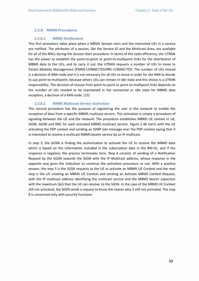
Next Generation Multimedia Multicast Services Chapter 2. State of the Art
53
2.5.8. MBMS Procedures
2.5.8.1. MBMS Notification
This first procedure takes place when a MBMS Session stars and the interested UEs in a service
are notified. The attributes of a session, like the Service ID and the Multicast Area, are available
for all of the RNCs during the Session Start procedure. In terms of the radio efficiency, the UTRAN
has the power to establish the point-to-point or point-to-multipoint links for the distribution of
MBMS data to the UEs, and to carry it out, the UTRAN requests a number of UEs to move to
Packet Mobility Management (PMM)-CONNECTED/RRC-CONNECTED. The number of UEs moved
is a decision of RAN node and it is not necessary for all UEs to move in order for the RAN to decide
to use point-to-multipoint, because others UEs can remain in idle state and this choice is a UTRAN
responsibility. The decision of choose from point-to-point or point-to-multipoint links depends on
the number of UEs needed to be maintained in the connected or idle state for MBMS data
reception, a decision of a RAN node. [13]
2.5.8.2. MBMS Multicast Service Activation
This second procedure has the purpose of registering the user in the network to enable the
reception of data from a specific MBMS multicast service. This activation is simply a procedure of
signaling between the UE and the network. The procedure establishes MBMS UE context in UE,
SGSN, GGSN and RNC for each activated MBMS multicast service. Figure 2.48 starts with the UE
activating the PDP context and sending an IGMP Join message over the PDP context saying that it
is interested to receive a multicast MBMS bearer service by an IP multicast.
In step 3, the GGSN is finding the authorization to activate the UE to receive the MBMS data
which is based on the information included in the subscription data in the BM-SC, and if the
response is negative, the process terminates here. Step 4 consists of sending of a Notification
Request by the GGSN towards the SGSN with the IP Multicast address, whose response in the
opposite way gives the indication to continue the activation procedure or not. With a positive
answer, the step 5 is the SGSN requests to the UE to activate an MBMS UE Context and the next
step is the UE creating an MBMS UE Context and sending an Activate MBMS Context Request,
with the IP multicast address identifying the multicast service and the MBMS bearer capacities
with the maximum QoS that the UE can receive, to the SGSN. In the case of the MBMS UE Context
still not activated, the SGSN sends a request to know the reason why it still not activated. The step
8 is concerned only with security functions.

Next Generation Multimedia Multicast Services Chapter 2. State of the Art
54
RAN
SGSN
UE
BM-SCGGSN
1. PDP Context Activation
2. IMGP Join
3. MBMS Authorization Request
3. MBMS Authorization Request
4. MBMS Notification Request
4. MBMS Notification Response
5. Request MBMS Context Activation
6. Activate MBMS Context Request
7. MBMS Notification Reject Request
7. MBMS Notification Reject Response
8. Security Functions
9. Invoke Trace
10. Create MBMS Context Request
11. MBMS Authorization Request
11. MBMS Authorization Response
12. MBMS Registration Request
12. MBMS Registration Response
13. Create MBMS Context Response
14. MBMS Registration Request
14. MBMS Registration Response
15. Provision of MBMS UE Context to RAN
16. Invoke Trace
17. Activate MBMS Context Accpet
Figure 2.48 – MBMS Multicast Service Activation
The SGSN creates an MBMS UE Context in step 10 and in step 11 deals with the GGSN finding
authorization for the activating UE, whose authorization is provided in the related response and
the BM-SC creates the MBMS UE Context. The step 12 happens when the GGSN does not have the
MBMS Bearer Context information for this service and the BM-SC answer to it with the
information needed. The final steps are: the creation of the MBMS UE context by the GGSN
sending it to the SSGN, if it is missing the MBMS Bearer Context information the SSGN will request
it, in step 15 the SGSN provides Iu mode RAN and the SSGN sends to the UE an Activate MBMS
Context Accept if the capabilities of the UE fulfill the requirements. [13]
2.5.8.3. MBMS Session Start Procedure
The BM-SC, when is ready to send data, initiates the MBMS Session Start and can be perceived as
a request to the all necessary resources in the network for the transfer of MBMS data to be
activated and to notify the interested UEs for the start of the transmission. In the meanwhile of
this procedure, session attributes, such as QoS and Multicast Area, are provided to the GGSN and
SGSN which have previously registered for the corresponding MBMS bearer service and to all
RNCs that are connected to a registered SGSN.
Next Generation Multimedia Multicast Services Chapter 2. State of the Art
55
Figure 2.49 presents the MBMS Session Start procedure for E-UTRAN and UTRAN for EPS where
the GGSN entity can be understood as the MBMS GW.
E-UTRAN/UTRANSGSN
UE
BM-SC
7. RAN Resource Setup
1. Session Start Request
2. Session Start Response
3. Session Start Request
4. Session Start Request
5. Session Start Response
6. Session Start Response
8. IP Multicast Join
9. MBMS data
10. MBMS data
MBMS GW
Figure 2.49 – MBMS Session Start procedure for U-TRAN/UTRAN for EPS
This procedure starts with the BM-SC sending a request message indicating the start of the
transmission and providing the session attributes, which message is sent to the MBMS GW listed
in the downstream nodes parameters of the related MBMS Bearer Context in the BM-SC. Step 2 is
the MBMS GW response with information for BM-SC to send MBMS data back. In step 3 the
session attributes and the list of MBMS control plane nodes in the MBMS bearer context are kept,
a transport network IP multicast address is allocated and the MBMS bearer context is created
where the request for the session start includes this attributes. The SGSN creates a MBMS bearer
context, storing the session attributes and sending a request message including them. The E-
UTRAN/UTRAN creates the MBMS bearer context, storing the session attributes and setting its
state to “Active” and answering with a response in step 5. This answer is relaying in the SGSN
towards the MBMS GW, after waiting for all nodes the information of the accepted multicast
distribution and to provide an SGSN IP address. In step 7 the radio resources for the transfer of
MBMS data to the interested UEs are established and in step 8 the IP Multicast distribution in the
UTRAN node is accepted, which joins the transport network IP multicast address. The last two
steps are the transmission of MBMS data where in the MBMS GW the data is sent using IP
multicast distribution to all joined nodes. [13]
2.5.8.4. MBMS Registration Procedure
It is the procedure where a downstream node informs an upstream node that it would like to
receive session attributes and data from a MBMS service, in order to distribute it. This procedure
constructs a distribution tree for the delivery of MBMS session attributes and data from the BM-
SC to the UEs interested in the service, and results in the set-up of a corresponding MBMS Bearer
Context in the nodes along the distribution tree, but the establishment of the user plane only will
be established by the Session Start procedure.

Next Generation Multimedia Multicast Services Chapter 2. State of the Art
56
The initiation of the MBMS Registration procedure can be triggered when: (i) the first MBMS UE
Context for a MBMS service, in the SGSN or GGSN, is created and the corresponding MBMS
Bearer Context is not already established in the node, (ii) a MBMS Registration Request is
received for a particular MBMS Service from a downstream node but the corresponding MBMS
Bearer Context is not established in the node or (ii) a DRNC knows that has UEs interested in some
MBMS service. This procedure is presented in Figure 2.50.
RNCSGSN BM-SCGGSN
4. MBMS Session Start Procedure
4. MBMS Registration Response
3. MBMS Registration Request
6. MBMS Registration Response
1. MBMS Registration Request
5. MBMS Registration Response
5. MBMS Session Start Procedure
2. MBMS Registration Request
6. MBMS Session Start Procedure
Figure 2.50 – MBMS Registration procedure
When RNC detects that has some UE interested in the MBMS bearer service, the DRNC sends the
request message to the related SGSN. In step 2, when the SGSN does not have the MBMS Bearer
Context, the SGSN has to create it in the “Standby” state and it sends the MBMS Registration
Request message to the GGSN. In the same way, if the GGSN does not have the MBMS Bearer
Context, it has to create it and it sends the request to the BM-SC. The BM-SC Proxy and Transport
Function add the identifier of the GGSN to the parameters in its MBMS Bearer Context and send
the response. The BM-SC initiates the Session Start procedure with the GGSN when the MBMS
Bearer Context is in the “Active” state. In step 5, the GGSN adds the identifier of the SGSN in the
list of parameters responding with a MBMS Registration response and if the MBMS Bearer
Context is “Active” it will begin the Session Start with the SGSN. The final step consists on the
SGSN adding the identifier of the RNC in the list of parameters in its MBMS Bearer Context,
sending the MBMS Registration Response message to the RNC and initiating the Session Start with
the DRNC if the MBMS Bearer Context is in the “Active” state. [13]
2.5.8.5. MBMS Session Stop Procedure
The Session Stop procedure is initiated when the BM-SC considers that the session has to be
terminated, which happens, normally, when there is no more MBMS data that justifies the release
of the user plane resources in the network to be transmitted in a long period of time. This
procedure is propagated to all the SGSNs and GGSNs registered in the MBMS bearer service and
to the RNCs that have established the interface Iu bearer plane with an SGSN.

Next Generation Multimedia Multicast Services Chapter 2. State of the Art
57
The MBMS Session Stop procedure is presented in Figure 2.51. Step 1 consists of the BM-SC
sending the request message to all GGSNs included in the parameters list with the purpose of
indication that the MBMS Session is terminated and that the bearer plane resources can be
released. The GGSN sends the stop request to all established SGSNs at the bearer plane and it also
releases the MBMS Bearer Context in the case of some broadcast MBMS bearer service
appearing. On step 3, the SSGN releases the bearer plane resources and sends the stop request
for all the RNCs that have a bearer plane established. The meaning of the step 3a is that if the RNC
uses IP multicast distribution, it is needed to disable the reception from the IP backbone of the
MBMS bearer service. Step 4 is the resources’ release and the MBMS Bearer Context becoming
the “Standby” state with the session stop. [13]
E-UTRAN/UTRANSGSN
UE
BM-SCGGSN
4. RAN Resource Release
1. Session Stop Request
1. Session Stop Response
2. Session Stop Request
3. Session Stop Request
3. Session Stop Response
2. Session Stop Response
3a. IGMPv3 Membership Resport
Figure 2.51 – MBMS Session Stop procedure for E-UTRAN and UTRAN for EPS
2.5.8.6. MBMS De-Registration Procedure
It is the procedure, from a downstream node to an upstream node, responsible to inform that no
more signaling, session attributes and data for a particular MBMS bearer service will be needed
and are to be removed from the distribution tree. The MBMS De-Registration procedure can be
triggered by: the SGSN or GGSN when the last MBMS UE Context is deleted from the node and
when the nodes list parameters is empty, the SGSN or GGSN when the last node registered de-
registers from a MBMS bearer service and the DRNC that is registered in a SGSN and deletes the
associated MBMS Service Context.
The BM-SC can also trigger the MBMS De-Registration procedure when the specific MBMS bearer
service is terminated. The procedure ends with the distribution tree for the session delivery
attributes and the MBMS data. The result of this procedure is the releasing of all MBMS Bearer
Context and related MBMS UE Contexts in the nodes of all distribution multicast tree. This second
procedure is presented in Figure 2.52 where the steps are of an easy perception, starting with the
request and the resources release from the BM-SC to the next node until arrives to the RNC,
where the release of all the affected radio resources happens, all MBMS UE Contexts and MBMS
Service Context. [13]

Next Generation Multimedia Multicast Services Chapter 2. State of the Art
58
RNCSGSN
UE
BM-SCGGSN
4. RAN Resource Release
1. Deregistration Request
1. Deregistration Response
3. MBMS Deregistration Request
3. MBMS Deregistration Response
2. MBMS Deregistration Response
2. MBMS Deregistration Request
Figure 2.52 – MBMS De-Registration procedure initiated by the BM-SC
2.5.8.7. MBMS Multicast Service Deactivation
The de-activation of the multicast service is a signaling procedure between the UE and the
network. It has removed the MBMS UE Context from the UE, SGSN and GGSN for a MBMS
multicast service. The de-activation can be triggered by the UE, GGSN, BM-SC or the SGSN. All of
those cases are scoped in the illustration of Figure 2.53.
At the step 1 the deactivation triggered by the UE starts, on step 3 starts from the BM-SC, in the
step 4 the GGSN initiates the deactivation and the SGSN starts from the steps 5 or 9. The MBMS
UE de-linking is performed at step 7 where the GRPS detachment happens, so the deactivation
from the SGSN can also start from this step. The PDP context linked to the MBMS UE context is
deactivated by the UE, SGSN or GGSN, and then the SGSN performs the MBMS deactivation
procedure starting in step 7, and the UE removes all MBMS UE Contexts locally.
RANSGSN
UE
BM-SCGGSN
8. RAN Resource Release
3. UE Removal Request
2. Leave Indication
4. MBMS UE Context Deactivation Request
7. MBMS UE De-Linking Response
4. MBMS UE Context Deactivation Response
1. IGMP Leave
5. Deactivate MBMS Context Request
6. Deactivate MBMS Context Response
7. MBMS UE De-Linking Request
9. Delete MBMS Context Request
10. Deactivation Indication
10. Deactivation Confirmation
11. MBMS Deregistration Request
11. MBMS Deregistration Response
12. Delete MBMS Context Response
13. Deregistration Request
13. Deregistration Response

Next Generation Multimedia Multicast Services Chapter 2. State of the Art
59
Figure 2.53 – MBMS Multicast Service Deactivation
2.5.8.8. MBMS Session Update Procedure
This procedure is called by the BM-SC or by the SGSN. The BM-SC in this procedure updates the
service area for an ongoing MBMS Broadcast service session. The SGSN also update the list of
service areas where the MBMS multicast users are located for an ongoing MBMS Multicast service
session.
2.5.8.8.1. Session Update for MBMS Multicast service
This procedure is triggered by the SGSN updating the list of the routing areas and informing the
RNCs that the list has changed. The SGSN sends the session update uniquely to the RNCs that are
affected by the change on the list. This procedure only happens during a MBMS Multicast service
session and when the SGSN has already sent the MBMS Session Start Request message to the
RNC. The RNC sends the acknowledgment for the MBMS Session Update Request back to the
SGSN.
2.5.8.8.2. Session Update for MBMS Broadcast Service
The BM-SC triggers this procedure when the service area for an ongoing MBMS Broadcast service
session has to be modified, which are the MBMS Service Area and the list of the download nodes
for GGSN. The node that receives this update will compare those attributes with the ones stored
in the MBMS Bearer Context. The Session Update procedure is presented in Figure 2.54.
RNCSGSN
UE
BM-SCGGSN
4. RAN Resources Setup or Release
1. Session Update Request
1. Session Update Response
3. MBMS Session Update Request
3. MBMS Session Update Response
2. MBMS Session Update Response
2. MBMS Session Update Request
Figure 2.54 – Session Update procedure


Next Generation Multimedia Multicast Services Chapter 3. IMS-MBMS Integration
61
Chapter 3. IMS – MBMS Integration
3.1. Introduction The MBMS technology, as one of many items of the 3GPP, is used to delivery multicast traffic over
IP for mobile UEs with a specific QoS. The key element of MBMS is the IP which is used to identify
the specific instance of the bearer service, which is concerted by an IP multicast address and a
network identifier, and also to manage all MBMS multicast services. Other relevant elements of
the MBMS architecture are the GGSN, which is responsible for the reservation of resources for
the UTRAN, the SGSN, which is capable of storing MBMS user specific context, and the BM-SC,
which is responsible for the initiation and termination of a session, as well as for the management
of the bearer resources, and also provides functionalities to both control/signaling and data
paths. Looking at the planning of the Next Generation Networks (NGN) IMS-MBMS integration,
the main functionalities should be solved in a useful way, which are (i) membership and
authorization where the IMS uses the HSS as the database and supports the role of membership
functions in BM-SC, (ii) security that is applied to the MBMS technology, (iii) service discovery, (iv)
QoS provisioning and (v) user profile management. MBMS enhancement is achieved with this
convergence and the corresponding architecture has to accomplish some features, such as control
mechanism of timing and management, signaling scheme consistent with IMS signaling, session
management based on RAN selection in convergence environment and QoS support for multicast
and broadcast services. [14] [15]
The IMS support of media delivery over multicast bearers has been identified during the definition
of the requirements of MBMS enhancements. The next citation clears it [16]:
«Multicast services allow IMS users and service providers to send multimedia to a group of IMS
users simultaneously in a unidirectional way of communication. The underlying network may be
able to support mechanisms that optimize the delivery of multimedia to the individual members of
that group».
To understand the implications for the new architecture, a study must be done based on possible
services to groups of IMS users that are registered at hot spots such as a football stadium that is,
without a doubt, one of the best locations to search what the users want from the service
providers. In the context of IMS, these services are the future for a better understanding and
applicability of multicast bearers. The study was focused in technical considerations and solutions
for the transport of IMS services over multicast bearers to enhance the IMS functions and to
provide better charging, security and service provision [17].
This Chapter describes the architectural concepts and procedures for IMS service functionalities
using multicast bearer based on MBMS bearer services that were described in Chapter 2 and is
defined in [18].
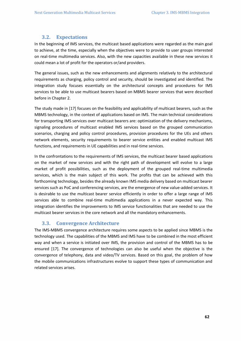
Next Generation Multimedia Multicast Services Chapter 3. IMS-MBMS Integration
62
3.2. Expectations In the beginning of IMS services, the multicast based applications were regarded as the main goal
to achieve, at the time, especially when the objectives were to provide to user groups interested
on real-time multimedia services. Also, with the new capacities available in these new services it
could mean a lot of profit for the operators or/and providers.
The general issues, such as the new enhancements and alignments relatively to the architectural
requirements as charging, policy control and security, should be investigated and identified. The
integration study focuses essentially on the architectural concepts and procedures for IMS
services to be able to use multicast bearers based on MBMS bearer services that were described
before in Chapter 2.
The study made in [17] focuses on the feasibility and applicability of multicast bearers, such as the
MBMS technology, in the context of applications based on IMS. The main technical considerations
for transporting IMS services over multicast bearers are: optimization of the delivery mechanisms,
signaling procedures of multicast enabled IMS services based on the grouped communication
scenarios, charging and policy control procedures, provision procedures for the UEs and others
network elements, security requirements to bearer service entities and enabled multicast IMS
functions, and requirements in UE capabilities and in real-time services.
In the confrontations to the requirements of IMS services, the multicast bearer based applications
on the market of new services and with the right path of development will evolve to a large
market of profit possibilities, such as the deployment of the grouped real-time multimedia
services, which is the main subject of this work. The profits that can be achieved with this
forthcoming technology, besides the already known IMS media delivery based on multicast bearer
services such as PoC and conferencing services, are the emergence of new value-added services. It
is desirable to use the multicast bearer service efficiently in order to offer a large range of IMS
services able to combine real-time multimedia applications in a never expected way. This
integration identifies the improvements to IMS service functionalities that are needed to use the
multicast bearer services in the core network and all the mandatory enhancements.
3.3. Convergence Architecture The IMS-MBMS convergence architecture requires some aspects to be applied since MBMS is the
technology used. The capabilities of the MBMS and IMS have to be combined in the most efficient
way and when a service is initiated over IMS, the provision and control of the MBMS has to be
ensured [17]. The convergence of technologies can also be useful when the objective is the
convergence of telephony, data and video/TV services. Based on this goal, the problem of how
the mobile communications infrastructures evolve to support these types of communication and
related services arises.
Next Generation Multimedia Multicast Services Chapter 3. IMS-MBMS Integration
63
The vision given by the C-MOBILE27 in Figure 3.1 faces multicast/broadcast transmissions and
group services delivered across several access networks with the added possibility of seamless
service mobility. This project has a clear strategy to define the integration of MBMS into the
architecture integration using a converged control plane based on IMS [19].
BCMCS(CDMA 2000)
WLANDVB-HMBMS(UMTS)
Content Content Content
Service and Content Providers
Broadcast/Multicast Controller
GroupManagement
SessionManagement
ServiceManagement
Content
Converged Control PlanIMS
Multiple Radio-Access Technologies
Heterogeneous UsersContent
Content
Content
Figure 3.1 – Converged Broadcast/Multicast Architecture by the C-MOBILE project
3.3.1. Architecture basics
Figure 3.2 illustrates the baseline architecture of IMS applications using the MBMS as a bearer.
Besides the functionalities of all entities kept by the same definitions, the use of an IMS AS is
identical as in the IMS and the UE needs to support MBMS and IMS functionalities as IMS
applications [17]. As we may see in Figure 3.2, the Policy Charging and Rules Function (PCRF)
entity is not yet defined for IMS applications using MBMS as a bearer. This is the starting point
architecture that will be evolved to the proposed convergence.
27 The C-Mobile Project started on the 1
st of March 2006. The objective of the project is to breed the evolution of the mobile broadcast
by providing enhancements to the 3GPP MBMS for systems beyond 3G. [20]

Next Generation Multimedia Multicast Services Chapter 3. IMS-MBMS Integration
64
GERAN
UTRANUE
CSCFs
MRFC/
MFRP
PCRF
HSS
BM-SCGGSN
IMS AS
SGSN
HSS
Figure 3.2 – Architecture of IMS applications using MBMS as a bearer
3.3.2. IMS session signaling and MBMS bearer services blend
This subchapter is to explain the procedures to use MBMS as a bearer in IMS applications. The
first step is for the IMS AS to find the UE capabilities and whether MBMS is supported at the
current location of the UE. With this information, the IMS AS has the power to decide to use the
MBMS bearer for the specific IMS application. The IMS AS should communicate to the BM-SC for
provisioning of the MBMS bearer service and the MBMS procedures will follow it [17]. Figure 3.3
illustrates an information flow for the procedures for IMS applications using MBMS as a bearer.
When the MBMS is used as a default bearer, the steps 2 and related procedures are not required.
P-CSCF SGSN GGSN BM-SC
CSCFs IMS AS
UE
Service Discovery
1. IMS Session Initiation
2. Capabilties Exchange
3. MBMS bearer decision
4. Service Provisioning
5. MBMS bearer signaling
6. IMS Session Modification
7. MBMS bearer activation procedures
8. MBMS session start procedures
9. Media Packets over MBMS bearer 9. Media Packets
10. IMS signaling for session tear-down
11. MBMS bearer deactivation procedures
Figure 3.3 – IMS applications using MBMS as a bearer flow

Next Generation Multimedia Multicast Services Chapter 3. IMS-MBMS Integration
65
3.3.2.1. IMS Multicast signaling with BM-SC
The first information exchanged when the service discovery procedure is made, includes the
related MBMS information, which can be the IP address if the multicast service is available in the
network before IMS session establishment.
In Figure 3.3, after the service discovery, the next step is the IMS session initiation. The second
step can be during or after the first one and is the exchange of MBMS capabilities which should
include UE capacities, QoS parameters and the indication of whether the MBMS is supported at
the UE current location. Step 3 is the decision of the IMS AS about what bearer should be used for
the IMS application based on the information exchanged in step 1, where the MBMS bearer is the
chosen one. In the next step, the IMS AS communicates with the BM-SC for assignment for a
unique multicast IP address and for provisioning of other information related to the MBMS bearer
services. Depending on the service, this interaction can be done before step 1.
At the MBMS bearer signaling step, the QoS parameters and the information related with the
bearer decision of the IMS AS are exchanged, and step 6 is the modification of the IMS session.
These two steps are not needed if the multicast service is already available in the network before
IMS session initiation. Step 7 and 8 are defined in [18]. tep 9 consists on the transmission of
MBMS data that takes place some period after the MBMS session starts and if the service in
question wants, this traffic can also flow in a point-by-point way. The last two steps are the IMS
signaling for session tear-down (10) and the MBMS bearer deactivation procedures (11).
An alternative option to Figure 3.3 consists of the same information flows, but with the first and
the second step being merged in just one, performing IMS session initiating and exchanging the
MBMS capabilities at the same time.
3.3.2.2. IMS multicast signaling without BM-SC dependence
A second possible approach of IMS multicast signaling is presented, which is not dependent on
the BM-SC in the network and the IMS multicast service delivery can be achieved by direct service
delivery and control. All BM-SC functions, besides security issues, are deployed by enhanced IMS
entities such as the IMS AS or the MRF.
As described in [17], the interaction between the GGSN and the IMS AS is fulfilled accordingly with
Gmb functions. The IMS service control in the IMS AS acts as the Membership function for user
service subscription management and user authorization. Proxy and Transport Function might be
realized by the media functions in IMS AS or IMS MRF, according to the service realization
requirements. Also, it is applicable for Session and Transmission Function. The IMS AS can use any
protocol layer to announce the multicast service information as SDP/SIP, SMS, PUSH, etc. The only
function that stays the same is security, defined in [18]. A better description of the IMS entities
enhancements will be described further in this Chapter.

Next Generation Multimedia Multicast Services Chapter 3. IMS-MBMS Integration
66
In Figure 3.4 ten important steps of the basic signaling flow of the direct service delivery for IMS
multicast services are showed. The first step is the service announcement initiated by the IMS
service host to the UE and it is included MBMS information. The session is initiated between the
UE and the entity that hosts the IMS service. The step 3 can be avoided if the network is already
configured and it is the exchange of the MBMS capabilities which will be used for decisions
related to the service delivery as UE capacities, multicast support indicator and parameters of
QoS. The next step, also avoidable for the same reason, is a natural consequence of the
information received and it is the bearer decision which is the case where the IMS service chooses
multicast as a bearer. Step 5 is the bearer activation started from the UE to SGSN and GGSN,
where the GGSN interacts with IMS multicast service host by controlling the multicast bearer.
SGSN GGSN
UE
1. Service Annoucement
7. Media Packets over MBMS bearer 7. Media Packets
MRF IMS AS
2. IMS Session Initiation
3. Capability Exchange
4. Bearer decison for MBMS multicast and
unicast
5. Multicast Bearer Activation Signaling
6. Multicast Bearer Control Signaling
8. MBMS Session Termination Signaling
9. Multicast Bearer Deactivation Signaling
10. Multicast Bearer Control Signaling
IMS Service Host
RAN
Figure 3.4 – IMS multicast service direct delivery signaling flows
At 7 the system is able to send media packets over the MBMS bearer between the GGSN and the
UE. Step 8 give us the end of the IMS multicast session. Then, the UE performs the bearer
deactivation procedures with SGSN and GGSN. Finally the multicast user and bearer information is
updated by the GGSN in step 10. [17]

Next Generation Multimedia Multicast Services Chapter 3. IMS-MBMS Integration
67
3.3.2.3. Bearer switching from Unicast to Multicast
The UE may give a hint to the IMS network to switch bearer when a user instructs it or when the
UE receives an indication from the PS network which shows that the UE MBMS context will be
deactivated. Under this condition, bearer switching from Multicast to Unicast is perhaps needed.
UTRAN
SGSN GGSN
UE 1. Media Packets over MBMS bearer
10. Media Packets
2. Capability Exchange
3. Switch bearers from unicast to multicast for
increasing users
6. Multicast Bearer Activation Signaling
7. Multicast Bearer Control Signaling
9. Deactivate or Modify the existing unicast PDP context
IMS Service Hostwith Multicast Capability
4. IMS Session Update
5. IMS Provision Response
8. IMS Session Update Final Response
10. Media Packets over MBMS bearer Figure 3.5 – Unicast to Multicast bearer switching signaling flows
The last entity in Figure 3.5 can be interpreted as separate nodes or as a single entity, depending
on the chosen view. In IMS signaling via BM-SC this entity is separated in BM-SC and IMS AS. On
the contrary, if it is IMS direct control signaling the entity it is represented only by the IMS AS.
The IMS service host decides to poll for the bearer switching by recounting UE capabilities, which
could be triggered by service level information, meaning, for example, the greatly increased users
in the IMS session. The steps to achieve this bearer switching are showed in Figure 3.5 and start
with an ongoing IMS session performed by a unicast bearer from the GGSN to the UE. The second
flow showed consists on the MBMS UE capabilities collection by the service and with this
information decides to switch all the UEs from the unicast bearers of the IMS session to the
multicast service bearer. In step 4 the IMS session is updated, and then the UE sends an IMS
provision response (183 – Session Progress) for resource reservation of the MBMS bearers to the
service host, and the UE contacts the GGSN for MBMS PDP context activation. The authentication
and authorization of the MBMS bearer activation is done by the GGSN and the IMS service host,
after the activation the UE answers with a 200 – OK. Step 9 is the deactivation or modification of
the existing unicast PDP context by the UE, and finally the media packets originated from the IMS
service arrive at the UE by the MBMS bearer instead of the unicast bearer [17].
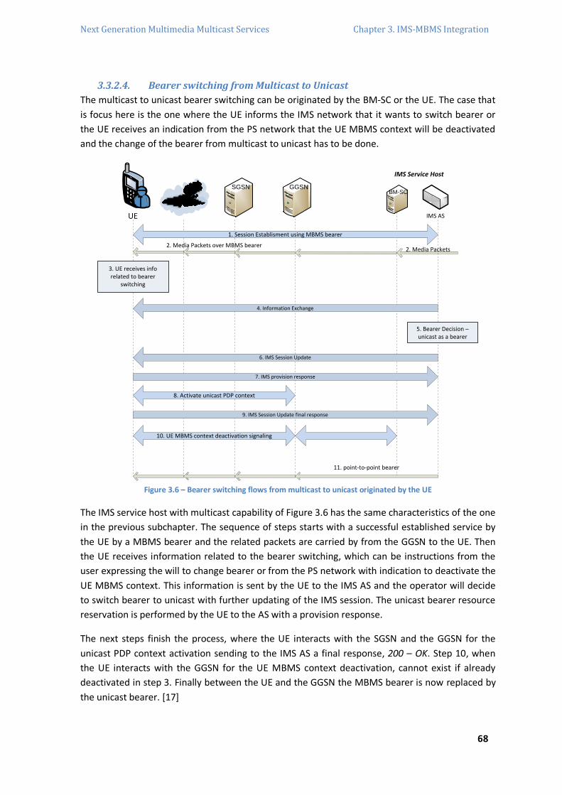
Next Generation Multimedia Multicast Services Chapter 3. IMS-MBMS Integration
68
3.3.2.4. Bearer switching from Multicast to Unicast
The multicast to unicast bearer switching can be originated by the BM-SC or the UE. The case that
is focus here is the one where the UE informs the IMS network that it wants to switch bearer or
the UE receives an indication from the PS network that the UE MBMS context will be deactivated
and the change of the bearer from multicast to unicast has to be done.
RAN
SGSN GGSN
UE
2. Media Packets over MBMS bearer
1. Session Establisment using MBMS bearer
3. UE receives info related to bearer
switching
10. UE MBMS context deactivation signaling
8. Activate unicast PDP context
4. Information Exchange
9. IMS Session Update final response
7. IMS provision response
11. point-to-point bearer
IMS AS
IMS Service Host
BM-SC
2. Media Packets
5. Bearer Decision – unicast as a bearer
6. IMS Session Update
Figure 3.6 – Bearer switching flows from multicast to unicast originated by the UE
The IMS service host with multicast capability of Figure 3.6 has the same characteristics of the one
in the previous subchapter. The sequence of steps starts with a successful established service by
the UE by a MBMS bearer and the related packets are carried by from the GGSN to the UE. Then
the UE receives information related to the bearer switching, which can be instructions from the
user expressing the will to change bearer or from the PS network with indication to deactivate the
UE MBMS context. This information is sent by the UE to the IMS AS and the operator will decide
to switch bearer to unicast with further updating of the IMS session. The unicast bearer resource
reservation is performed by the UE to the AS with a provision response.
The next steps finish the process, where the UE interacts with the SGSN and the GGSN for the
unicast PDP context activation sending to the IMS AS a final response, 200 – OK. Step 10, when
the UE interacts with the GGSN for the UE MBMS context deactivation, cannot exist if already
deactivated in step 3. Finally between the UE and the GGSN the MBMS bearer is now replaced by
the unicast bearer. [17]
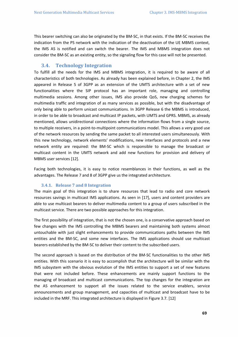
Next Generation Multimedia Multicast Services Chapter 3. IMS-MBMS Integration
69
This bearer switching can also be originated by the BM-SC, in that exists. If the BM-SC receives the
indication from the PS network with the indication of the deactivation of the UE MBMS context,
the IMS AS is notified and can switch the bearer. The IMS and MBMS integration does not
consider the BM-SC as an existing entity, so the signaling flow for this case will not be presented.
3.4. Technology Integration To fulfill all the needs for the IMS and MBMS integration, it is required to be aware of all
characteristics of both technologies. As already has been explained before, in Chapter 2, the IMS
appeared in Release 5 of 3GPP as an extension of the UMTS architecture with a set of new
functionalities where the SIP protocol has an important role, managing and controlling
multimedia sessions. Among other issues, IMS also provide QoS, new charging schemes for
multimedia traffic and integration of as many services as possible, but with the disadvantage of
only being able to perform unicast communications. In 3GPP Release 6 the MBMS is introduced,
in order to be able to broadcast and multicast IP packets, with UMTS and GPRS. MBMS, as already
mentioned, allows unidirectional connections where the information flows from a single source,
to multiple receivers, in a point-to-multipoint communications model. This allows a very good use
of the network resources by sending the same packet to all interested users simultaneously. With
this new technology, network elements’ modifications, new interfaces and protocols and a new
network entity are required: the BM-SC which is responsible to manage the broadcast or
multicast content in the UMTS network and add new functions for provision and delivery of
MBMS user services [12].
Facing both technologies, it is easy to notice resemblances in their functions, as well as the
advantages. The Release 7 and 8 of 3GPP give us the integrated architecture.
3.4.1. Release 7 and 8 Integration
The main goal of this integration is to share resources that lead to radio and core network
resources savings in multicast IMS applications. As seen in [17], users and content providers are
able to use multicast bearers to deliver multimedia content to a group of users subscribed in the
multicast service. There are two possible approaches for this integration.
The first possibility of integration, that is not the chosen one, is a conservative approach based on
few changes with the IMS controlling the MBMS bearers and maintaining both systems almost
untouchable with just slight enhancements to provide communications paths between the IMS
entities and the BM-SC, and some new interfaces. The IMS applications should use multicast
bearers established by the BM-SC to deliver their content to the subscribed users.
The second approach is based on the distribution of the BM-SC functionalities to the other IMS
entities. With this scenario it is easy to accomplish that the architecture will be similar with the
IMS subsystem with the obvious evolution of the IMS entities to support a set of new features
that were not included before. These enhancements are mainly support functions to the
managing of broadcast and multicast communications. The top changes for the integration are
the AS enhancement to support all the issues related to the service enablers, service
announcements and group management, and capacities of multicast and broadcast have to be
included in the MRF. This integrated architecture is displayed in Figure 3.7. [12]
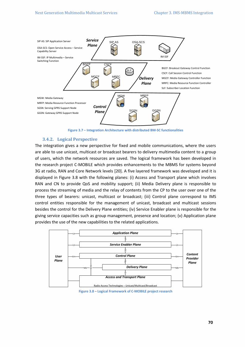
Next Generation Multimedia Multicast Services Chapter 3. IMS-MBMS Integration
70
SIP AS OSA-SCS
IM-SSF
BGCF CSCF
SLF
MGCF MRFC
MGW MRFP
SGSN GGSN
ServicePlane
ControlPlane
DeliveryPlane
SIP AS: SIP Application Server
OSA-SCS: Open Service Access – Service Capability Server
BGCF: Breakout Gateway Control Function
CSCF: Call Session Control Function
MGCF: Media Gateway Controller Function
MRFC: Media Resource Function Controller
SLF: Subscriber Location Function
MGW: Media Gateway
MRFP: Media Resource Function Processor
SGSN: Serving GPRS Support Node
GGSN: Gateway GPRS Support Node
IM-SSF: IP Multimedia – Service Switching Function
Figure 3.7 – Integration Architecture with distributed BM-SC functionalities
3.4.2. Logical Perspective
The integration gives a new perspective for fixed and mobile communications, where the users
are able to use unicast, multicast or broadcast bearers to delivery multimedia content to a group
of users, which the network resources are saved. The logical framework has been developed in
the research project C-MOBILE which provides enhancements to the MBMS for systems beyond
3G at radio, RAN and Core Network levels [20]. A five layered framework was developed and it is
displayed in Figure 3.8 with the following planes: (i) Access and Transport plane which involves
RAN and CN to provide QoS and mobility support; (ii) Media Delivery plane is responsible to
process the streaming of media and the relay of contents from the CP to the user over one of the
three types of bearers: unicast, multicast or broadcast; (iii) Control plane correspond to IMS
control entities responsible for the management of unicast, broadcast and multicast sessions
besides the control for the Delivery Plane entities; (iv) Service Enabler plane is responsible for the
giving service capacities such as group management, presence and location; (v) Application plane
provides the use of the new capabilities to the related applications.
Application Plane
Service Enabler Plane
Control Plane
Delivery Plane
Access and Transport Plane
Radio Access Technologies – Unicast/Multicast/Broadcast
ContentProvider
Plane
UserPlane
Ut Ut
Ut
Gm
Mb
Ut
Gm
Mb
Gm
b
AP
IISC
Mp
Gi
Figure 3.8 – Logical Framework of C-MOBILE project research

Next Generation Multimedia Multicast Services Chapter 3. IMS-MBMS Integration
71
The User Plane is the end-user connected to the mobile network which receives the specific
content, where in the opposite side appears the Content Provider Plane that is responsible for the
content delivering to the side of the user domain. [12]
3.5. IMS-MBMS Architecture evolved The MBMS technology alone via BM-SC provides multicast and broadcast communications since it
has its own mechanisms of user accounting, charging, security and QoS, among others. To provide
the same services in a next generation network, the MBMS has to be enhanced. The IMS-MBMS
architecture has the goal to support some functions, such as the IMS consistency signaling for
efficient multicast signaling, group management with context-awareness communities, dynamic
multicast group address allocation, scheduling and congestion control with adaptive solutions
based on RAN feedback, session management with RAN/bearer selection in a converged
environment, QoS support for multicast/broadcast services and transcoding strategies for
provisioning of multi-layer services supporting user-cases such as layered codecs and location-
dependent transmissions [11].
3.5.1. Architectural Topics
The IMS technology is the architectural convergence key chosen for session control. As already
mentioned the IMS does not support delivery of multicast or broadcast services which is not good
for scalability. For instance, with an enhancement in the MRF entity to support multicast delivery
it would be possible to improve a service provider resource usage.
The converged architecture will make IMS multicast technology enabled, so it will be possible to
send multimedia content to a group of IMS users through a multicast capable technology as a
bearer where the MBMS is the delivery multicast technology. The first integration option was to
allow IMS applications to use MBMS where all the functionalities and structure was maintained as
the same as possible. This study approach [17] showed the BM-SC entity inside the IMS
architecture to support MBMS bearers, but the final considerations was not good, because there
were problems to solve about the duplicate functionalities and providing integrated interfaces.
When there are more than one possible multicast/broadcast bearers, the IMS has the power do
chose, in some way, which bearer to use and the decision has to be based on the related
application, capacities of the UE, the multicast or broadcast network access or/and QoS
parameters. The second approach of MBMS convergence says that the functionalities of the BM-
SC had to be distributed over IMS entities and service enablers, because the multicast/broadcast
support functions has to be placed at the service enabler layer and session control layer.
3.5.2. Functions Integration
As was already explained in Chapter 2, the BM-SC is able to supply mixed data path and control
management functionalities. These functionalities have to be abstracted in a way that they can be
reused by several technologies. In Figure 3.9 is possible to see the BM-SC functional structure
inside a UMTS network with the interfaces and protocols that are used.
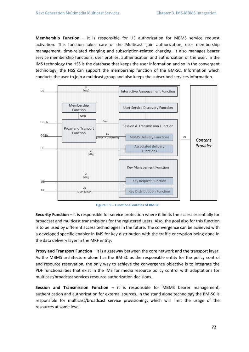
Next Generation Multimedia Multicast Services Chapter 3. IMS-MBMS Integration
72
Membership Function – it is responsible for UE authorization for MBMS service request
activation. This function takes care of the Multicast ‘join authorization, user membership
management, time-related charging and subscription-related charging. It also manages bearer
service membership functions, user profiles, authentication and authorization of the user. In the
IMS technology the HSS is the database that keeps the user information and so in the convergent
technology, the HSS can support the membership function of the BM-SC. Information which
conducts the user to join a multicast group and also keeps the subscribed services information.
Content Provider
Key Distributioon Function
Key Request Function
Key Management Function
Associated delivery Functions
MBMS Delivery Functions
Session & Transmission Function
User Service Discovery Function
Interactive Annoucement Function
Membership Function
Proxy and Tranport Function
UE
GGSN
GGSN
UE
UE
UE
Gmb
Gmb
Gi[http]
Gi[http]
Gi[UDP, MIKEY]
Gi[http]
GiGi
[UDP/RTP, UDP/FLUTE]
Figure 3.9 – Functional entities of BM-SC
Security Function – it is responsible for service protection where it limits the access essentially for
broadcast and multicast transmissions for the registered users. Also, the goal also for this function
is to be used by different access technologies in the future. The convergence can be achieved with
a developed specific enabler in IMS for key distribution with the traffic encryption being done in
the data delivery layer in the MRF entity.
Proxy and Transport Function – it is a gateway between the core network and the transport layer.
As the MBMS architecture alone has the BM-SC as the responsible entity for the policy control
and resource reservation, the only way to achieve the convergence objective is to integrate the
PDF functionalities that exist in the IMS for media resource policy control with adaptations for
multicast/broadcast services resource authorization decisions.
Session and Transmission Function – it is responsible for MBMS bearer management,
authentication and authorization for external sources. In the stand alone technology the BM-SC is
responsible for multicast/broadcast service provisioning, which will limit the usage of the
resources at some level.

Next Generation Multimedia Multicast Services Chapter 3. IMS-MBMS Integration
73
The BM-SC is responsible for the resources allocation to bearer services and to provide the GGSN
with transport associated parameters, such as QoS and MBMS service area. The MBMS assumes
that the BM-SC is in charge of policy control and can obviously benefit with the integration of IMS
PDF functionality for policy control. The BM-SC also collects Quality of Experience (QoE) and
reception acknowledges reports related to streaming and download delivery. So, for the
convergence the IMS can easily be able to manage the reception of these reports through a given
AS responsible for session management of multicast/broadcast services.
Service Discovery Function – the BM-SC provide services announcements for multicast and
broadcast MBMS user services that include the media descriptions specifying the media to be
delivered as part of an MBMS user service. It is also able to provide for the UE the MBMS session
descriptions specifying the MBMS sessions to be delivered as part of an MBMS user services. New
service enablers developed for IMS, such as group management, can be the perfect tools for
service announcement, bringing location and context-sensitivity into MBMS that were not
provided before.
The previous functions integration descriptions are based on the work in [11].
3.5.3. Convergent Architecture
The technology evolution arrives to the possibility of fully implemented multicast and broadcast
services in a consistent IP-based NGN architecture. Besides the current work on LTE and SAE,
enhancements of PS technology are expected to compete with the fast growth in IP traffic. In the
IMS and MBMS architecture integration proposal, as suggested in [11], the MBMS BM-SC
functions are fully distributed among the existing network entities as was already focused in this
Chapter. A centralized BM-SC disappears and the IP multicast is assumed as common transmission
layer besides some functions being generalized to be compatible with any access technology. A
new layered design based on the IMS technology is proposed in Figure 3.10 [11], where the
delivery plane is divided in access and delivery plane at the same level. The access plane is used
by the end user to achieve access to the network and the delivery plane is concerned with the
converged IP layer. The control plane introduces the Security Gateways (SEGs) which are entities
on the edges of the IP security domains that are used to secure native IP protocols [21]. The
service plane is divided in application plane and service enabler plane. The following subchapters
have the description of each plane.

Next Generation Multimedia Multicast Services Chapter 3. IMS-MBMS Integration
74
CSNetworks
RAN
External IMSNetworks
HSS
Access Plane
Control Plane
AS AS
Application Plane
Other KeyEnablerMulticast
BroadcastService Enabler
PresenceServer
GroupEnabler
Service Enabler Plane
UE
Evolved Packet Core
Delivery Plane
S-CSCF I-CSCFCSCF
P-CSCF BGCF
SEG
MGCFMRFC
MRF
MRFP
IM-GW
MRF Evoluted
Content Provider
Multimedia Services
PCRF
Figure 3.10 – Evolved IMS-MBMS architecture
3.5.3.1. Access and Transport Plane
The access and transport plane have nothing to do with the standards of MBMS. In this evolution,
it is considered a new UMTS packet core where new mechanisms are introduced by enhanced IP
based multicast and mobility mechanisms. This path follows the evolution defined in [22] with the
support of multicast mobility. The convergence result is the IP packet network closer to the RAN
which permits IP convergence closer to the user and the access is reduced to a smaller area.
Obviously, another consequence is the work ability between various types of access networks.
The architecture proposal consists on a redefinition of the Gx28 interface in order to get along with
enhanced support to multicast bearers creation, permitting a user to join a multicast group, to set
multicast related QoS parameters, to provide generation and transmission of charging vectors for
online and offline charging.
3.5.3.2. Media Delivery Plane
The Media Delivery Plane is the layer responsible for the transport and pre-processing of data,
where also is projected some Media Delivery Function Processor (MDFP) entities. The MDFP will
extend the MRFP defined earlier and the MDFP with the Media Delivery Function Controller
(MDFC) provides the ciphering of media for multicast/broadcast security, error correction coding,
mixing of different media streams and transcoding. The MDFP can be considered as a gateway
between the Content Provider and the Evolved Packet Core which handle with the enhanced
delivery functions of group and session management. The interface between both entities has to
enhance accordingly with the implications over the control of multicast bearers and will be
considered the SIP protocol. [11]
28 The Gx interface is for interactions with the Policy Control Enforcement Function (PCEF) that is inside the evolved packet network
architecture that controls the allocation of resources, the mapping of QoS parameters and the enforcement of charging and pol icy.

Next Generation Multimedia Multicast Services Chapter 3. IMS-MBMS Integration
75
3.5.3.3. Control Plane
The developed Control Plane consists of CSCFs, HSS, PCRF and MRF divided in MDFC and MDFP.
The Policy Control Resource Function (PCRF) is introduced in SAE/LTE as an extension of the IMS
PDF component for better admission, charging and QoS mechanisms, and it is responsible for QoS
aspects, policy management and charging functions. On this matter, the proposal introduced in
[11] is to enable the CSCF capability to request policy decisions to the PCRF entity for
multicast/broadcast services announced by application functions. This PCRF entity needs the
support of an enhanced user database to be able to get the user profiles for policy decisions, and
the HSS will suffer some enhancements to be able to respond to these requirements. The
enhanced 3GPP MRFC, the MDFC, provides services for conferencing and announcements to a
user or media transcoding in the IMS architecture. In order to control the content sources, the
MDFC has to be able to support CPs to deliver specific content to a specific unicast, multicast or
broadcast address. The functions of this entity are about reservation and administration of
multicast addresses.
3.5.3.4. Service Enabler Plane
To provide multicast and broadcast services, the definition of a Multicast/Broadcast – Service
Enabler (MB-SE) is proposed in [11], as is showed in Figure 3.11, where some functions already
existed in the BM-SC Release 6. These functions are: security management, service description
and service guide aggregation for broadcast and multicast services, high level content scheduling,
statistics collection for streaming and download deliveries, QoE statistics collection for streaming
and group management. The Statistics Collector collects and aggregates the status of the Radio
Access and the Core Network, and also stores and analysis QoS reports whose results are used by
the Service Scheduling Management to scheduling decisions. The Session Management Function
selects the multicast or unicast transport. The scheduling functions provide the Service Guide
Aggregator with the information about the calculated timeslot for each service and to support
efficiency the Service Scheduling Management depends on Group Management functionalities.
The Service Protection/Key Management entity is responsible for the key updates service
delivering based on previous UE registrations to receive these updates, which was made before
by the old BM-SC based on HTTP. In the new architecture it is proposed to use Subscribe/Notify
procedures allowing the UEs to register or receive key updates and acquire them when available
from the BM-SC. Other security issues in the BM-SC are also distributed, such as authentication
across the IMS core and the ciphering and traffic key generation that is taken care by the MDFP
entity.

Next Generation Multimedia Multicast Services Chapter 3. IMS-MBMS Integration
76
Content Providers
Plane
Mcast / Multicast Service Plane
ServiceEnabler Plane
UserPlane
Application PlaneUt
IMS-based Control Plane
StatisticsCollector
SchedulingManagement
Service Protection/KeyManagement
Key Distribution Function
Key Request Fcuntion
Service/Session Description
Service Guide Aggregator
Presence Server
M* - Membership Function
Group Enabler
Other enhanced enablers
HSS
M* - Membership FunctionPCRF
Media Delivery Function Controller (MDFC) or MRFC
CongestionController
Session Scheduling Controller
ContentAdaptation
MDFP Controller MDFP Location M* - Session Manager
P/I/S-CSCF M* - Session and
Transmission
Media Delivery Plane
MDFP or MDFP
Media Processor/Transcoder
M* - Proxy and Transport
Delivery Group Manager
Delivery Session
Manager
Media Delivery Function Processor
(MDFP)
Content Manager
Streaming and
Download Source
Access and TransportPlane
Evolved Packet Core M* - Proxy and Transport
M* - UE BS Context
Management
PCEF
Mb
Gmb
Ut
Ut
Go/Gx
APIs
Session Management Function
Sh/Dh
Gm
Gq/Rx
Gi
M* Distributed BMSC Functionality (M – Multicast)
Figure 3.11 – IMS and MBMS convergence details
3.6. IMS-MBMS Signaling procedures As everything else in the IMS and MBMS integration updates to the signaling procedures are
required. IMS signaling was only prepared to establish unicast transmissions between users, now
the signaling has to permit the delivering of multimedia content to a group of users in the IMS
network with the use of multicast and broadcast bearers.
3.6.1. Service Activation
The multicast Service Activation is the process of a user joining a multicast group informing which
kind of data it wants to receive from the multicast bearer. Besides the procedures already
mentioned in Chapter 2 about the MBMS standards, in this integration the main topic is to
consider the SIP INVITE message as a trigger to the join procedure as the [23] defends it. Besides
the codecs and multicast address negotiation, the user can make the MBMS join procedure.
The proposed approach of [12] is illustrated in Figure 3.12 where if a user wants a service, will
request it by sending a SIP MESSAGE to the AS just with the Service Identification, permitting to
the network know which are the users that are interest in that service. The big advantage of this
approach is the resources saving by postponing the context creations and establishment of the
session to a time immediately before the start of the session. Other advantages are the content
adaptation and flexibility. The multicast address being created in the beginning of a session makes
possible the accuracy in a group creation possible.

Next Generation Multimedia Multicast Services Chapter 3. IMS-MBMS Integration
77
RANSGSN P-CSCF
UE
AS(SME)GGSN S-CSCF
CPPCRF
MDF
User Subscription
Service Annoucement
Message (Service, no SDP)
Message (Service, no SDP)
Message (Service, no SDP)
200 OK
200 OK
200 OK
Figure 3.12 – Service Activation Procedure in the integration view
3.6.2. Session Start
The Session Start, illustrated in Figure 3.13, is the procedure where the data is ready to send in all
the data transmissions. All the sessions are established in this procedure and the network
resources are further reserved. First of all, the network needs to create the multicast path and the
resources allocations are triggered by the AS to the Media Delivery Function (MDF). The content
has to be adapted due to the different multicast groups that need different kinds of content
quality, so the AS sends an INVITE message to the MDF for every multicast IP. The next step is the
invitation to the joined users, which is a SIP INVITE message with the SDP for the session which
includes the correspondent multicast address to deliver the content with a specific quality. The AS
checks the respective HSS to know the UE capacities which increase the flexibility of the system
enabling the user to have a better service depending on the type of the user device. The UE
accepts the parameters and proceeds to the MBMS Service Activation procedure, creating the UE
contexts associated to one of these multicast addresses over the involved network elements. The
authorization for the UE is given by the PCRF instead of the BM-SC, then the UE sends the SIP 200
– OK message including the activated multicast address to the AS, which acknowledges this by
sending an ACK message. To avoid future problems, the network should not invite all the users at
the same. After all the invites, the AS will control and establish a session between the CP and the
MDF, starting to send a SIP INVITE message without SDP to the CP. The CP answers with a 200 –
OK which has its SDP that is forwarded by the AS to the MDF using a SIP INVITE message and at
this time the MDF starts the MBMS Session Start procedure as described in [13]. The MBMS PDP
Contexts are activated and the network resources become unavailable for other services when a
multicast bearer is activated between the MDF and all the assigned users. Finally, the MDF sends
the 200 – OK message to the AS that acknowledges both MDF and CP entities creating the session.
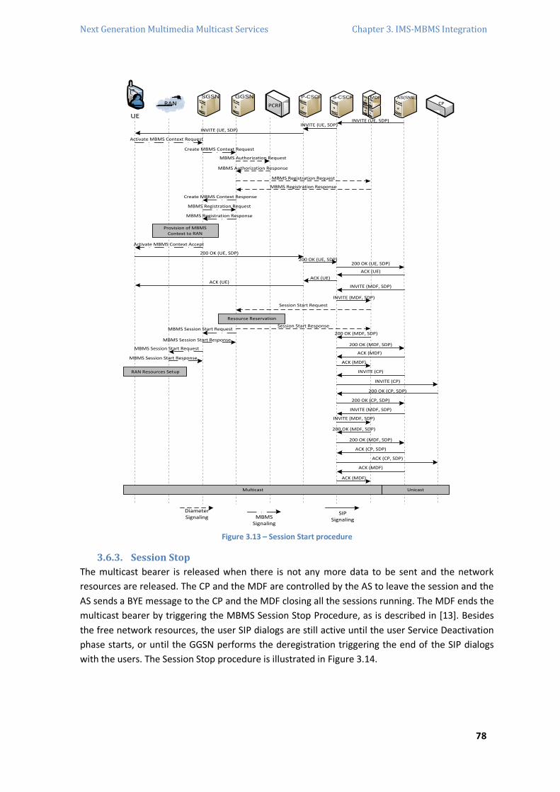
Next Generation Multimedia Multicast Services Chapter 3. IMS-MBMS Integration
78
RANSGSN P-CSCF
UE
AS(SME)GGSN S-CSCF
CPPCRF
MDF
INVITE (UE, SDP)INVITE (UE, SDP)
INVITE (UE, SDP)
Activate MBMS Context Request
Create MBMS Context Request
MBMS Authorization Request
MBMS Authorization Response
MBMS Registration Request
MBMS Registration Response
Create MBMS Context Response
MBMS Registration Request
MBMS Registration Response
Provision of MBMS Context to RAN
Activate MBMS Context Accept
200 OK (UE, SDP)
200 OK (UE, SDP)200 OK (UE, SDP)
ACK (UE)
ACK (UE)ACK (UE)
INVITE (MDF, SDP)
INVITE (MDF, SDP)
Session Start Request
Resource Reservation
Session Start ResponseMBMS Session Start Request
MBMS Session Start Response
MBMS Session Start Request
MBMS Session Start Response
RAN Resources Setup
Multicast Unicast
ACK (MDF)
200 OK (MDF, SDP)
INVITE (MDF, SDP)
200 OK (MDF, SDP)
ACK (CP, SDP)
ACK (CP, SDP)
ACK (MDF)
INVITE (MDF, SDP)
200 OK (CP, SDP)
200 OK (CP, SDP)
INVITE (CP)
INVITE (CP)
ACK (MDF)
ACK (MDF)
200 OK (MDF, SDP)
200 OK (MDF, SDP)
DiameterSignaling MBMS
Signaling
SIPSignaling
Figure 3.13 – Session Start procedure
3.6.3. Session Stop
The multicast bearer is released when there is not any more data to be sent and the network
resources are released. The CP and the MDF are controlled by the AS to leave the session and the
AS sends a BYE message to the CP and the MDF closing all the sessions running. The MDF ends the
multicast bearer by triggering the MBMS Session Stop Procedure, as is described in [13]. Besides
the free network resources, the user SIP dialogs are still active until the user Service Deactivation
phase starts, or until the GGSN performs the deregistration triggering the end of the SIP dialogs
with the users. The Session Stop procedure is illustrated in Figure 3.14.

Next Generation Multimedia Multicast Services Chapter 3. IMS-MBMS Integration
79
RANSGSN P-CSCF
UE
AS(SME)GGSN S-CSCF
CPPCRF
MDF
BYE (Session Stop)
BYE (CP)
BYE (Session Stop)
200 OK (Session Stop)
200 OK (CP)
Session Stop Request
Resources Release
MBMS Session Stop Response
MBMS Session Stop Request
MBMS Session Stop Request
RAN Resources Release
DiameterSignaling MBMS
Signaling
SIPSignaling
Session Stop Response
MBMS Session Stop Response
Figure 3.14 – Session Stop Procedure
3.6.4. Service Deactivation
This procedure happens when a given user wants to leave a multicast group meaning that the
user doesn’t want to be in the service anymore, so the user will be prevented to receive more
multicast content of the related MBMS bearer service. This procedure starts with the sending of a
BYE SIP message from the UE with the destination to a service public SIP URI, and the AS answers
with a 200 – OK indicating the end of the session. A situation to be noticed is when the last user is
leaving the multicast group, the AS tells to the MDF to release the multicast bearer and, in the
meanwhile, the UE starts the MBMS Service Deactivation signaling to release the established UE
context. Also, the PCRF should be informed about the end of the multicast session after the
MBMS deregistration procedure. [12] Figure 3.15 illustrates the Service Deactivation procedure.
RANSGSN P-CSCF
UE
AS(SME)GGSN S-CSCF
CPPCRF
MDF
200 OK (Service)
BYE (Service)
BYE (Service)
200 OK (Service)
BYE (Service)
Remove Authorization
Delete MBMS Context Request
RAN Resources Release
DiameterSignaling
MBMSSignaling
SIPSignaling
BYE (MDF)
BYE (MDF)
200 OK (MDF)
200 OK (MDF)
200 OK (Service)
Deactivate MBMS Context Request
Deactivate MBMS Context Response
MBMS UE De-Linking Request
MBMS UE De-Linking Response
Deactivation Indication
Deactivation Response
MBMS Deregistration Request
MBMS Deregistration Response
Resources Release
Delete MBMS Context Response
MBMS Deregistration Request
MBMS Deregistration Response
Figure 3.15 – Service Deactivation Procedure

Next Generation Multimedia Multicast Services Chapter 3. IMS-MBMS Integration
80
3.7. Multicast/Broadcast Services Evolution New business opportunities for everyone arrive with the convergence of the multicast and
broadcast services and the all-IP environments. The new approach to the group services promotes
a lot more intelligent deployment and the access to these groups requires a specific request that
can be transferred to the AS or to the content provider. Now it is possible for the group services
go through specific logic and provide different content to different users, depending on a range of
aspects, as the transcoding of information according to the access network, or the selection of the
content according to the user preferences or subscriptions. An advantage of this convergence is
the possibility of different feature deployment, creating a multicast tree inside the wireless
network to reach only the cells that are needed to provide the service for the multicast group.
One of the motivations of this integration was to enable interactive group based and context-
aware multicast services. As already mention before, when the goal was to distribute the BM-SC
functionalities a new enabler rise. Figure 3.16 shows the structure of this new enabler, MB-SE,
and the interaction with other enablers, provided by the converged framework. As it can be seen,
multicast services can interact with other IMS-OMA (Open Mobile Alliance) enablers to carry out
functions like scheduling, service discovery, charging and security. After all these discussion and
with this scenario, it is shown that the convergent architecture makes multicast transmissions
possible.
Service/Session Description
Content Provider
Session Management Function
Multicast Broadcast – Service Enabler(MB-SE)
Service Guide Aggregator
StatisticsCollector
SchedulingManagement
Service Protection/KeyManagement
Key Request Function
Key Distribution Function
Session Management Enabler
Converged IMS-MBMS CoreConverged IMS-MBMS Core
ChargingEnabler
SecurityEnabler
Presence Enabler
Device Management
Group Management
Enabler
Service Discovery Enabler
MB-SE
Other Enablers
Multicast Specific
Figure 3.16 – Functional Structure of the Broadcast/Multicast Service Enabler (MB-SE)
This tree creation for streaming distribution creates an added dimension to group services,
especially to subscribed services related to information. The subscribed services related with
context information leads to the creation of different multicast groups which can vary with
information such as location, weather, or something else that matters.

Next Generation Multimedia Multicast Services Chapter 3. IMS-MBMS Integration
81
The main point of this study is essential the multicast transmission which is the one that makes
the difference and the future profit for the operator or/and to the content provider. Besides the
multicast, the broadcast services are the ones that the same content goes to all users without
choices and where the operator does not have profit because is for free. But of course, these
kinds of services receive all the benefits of the integration made to the architecture.
The evolution of the broadcast services becomes better on the advertising and content
authorization. The integration of broadcast services allows a much better effective exploitation of
advertising and only after the user will subscribe to a multicast service. The content authorization
appears here due to the increase of broadcasters’ limitations on content distribution, according to
aspects related to objectionable contents. With a convergent environment, all these contents can
be viewed, because all the contents will be transmitted without any restrictions where the user
can chose to see what he wants as a pay-per-view transmission. Any restrictions made have to be
in the subscription procedure, where the users would be allowed, or not, to receive such
contents. [11]
3.8. Briefing In this chapter, a proposed extension to IMS for multicast support was documented. In this
convergence the required signaling flows between the implicated IMS entities, also described in
this Chapter and is important to mention the considerable amount of network resources savings
achieved with this approach by creating all the sessions and contexts at the moment of the data
delivery. Also, the C-MOBILE layered framework was introduced, where the functions of MBMS
are distributed among the enhanced IMS entities, instead of having two separated subsystems
where the BM-SC entity had to exist. Besides the saved resources, the investment of deploying
new network components is also reduced and optimizes the usage of network resources by
delivering multimedia content over multicast transmissions. This evolution of the IMS technology
gives to it the possibility to work in multicast and broadcast modes. Such new IMS capacities
facilitate the delivery of interactive and personalized multimedia applications.

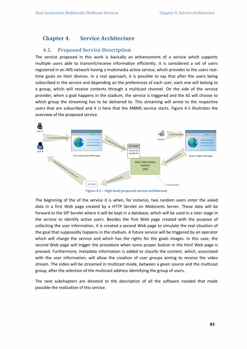
Next Generation Multimedia Multicast Services Chapter 4. Service Architecture
83
Chapter 4. Service Architecture
4.1. Proposed Service Description The service proposed in this work is basically an enhancement of a service which supports
multiple users able to transmit/receive information efficiently. It is considered a set of users
registered in an IMS network having a multimedia active service, which provides to the users real-
time goals on their devices. In a real approach, it is possible to say that after the users being
subscribed in the service and depending on the preferences of each user, each one will belong to
a group, which will receive contents through a multicast channel. On the side of the service
provider, when a goal happens in the stadium, the service is triggered and the AS will choose to
which group the streaming has to be delivered to. This streaming will arrive to the respective
users that are subscribed and it is here that the MBMS service starts. Figure 4.1 illustrates the
overview of the proposed service.
User A
User B
REAL-TIME GOALS SERVICE
(AS)
DATABASE
UserA infoUserB info
...
2. Collected User Information
“Operator”
3. Press the Button
Goal video6. Streaming Activation
7. Streaming Multicast for selected users
User Subscription Web page
1. Insert data on Web page
4. Metadata Inform
ation
Service Trigger Web page
5. Group Selection Figure 4.1 – High-level proposed service architecture
The beginning of the of the service it is when, for instance, two random users enter the asked
data in a first Web page created by a HTTP Servlet on Mobicents Server. These data will be
forward to the SIP Servlet where it will be kept in a database, which will be used in a later stage in
the service to identify active users. Besides the first Web page created with the purpose of
collecting the user information, it is created a second Web page to simulate the real situation of
the goal that supposedly happens in the stadium. A future service will be triggered by an operator
which will charge the service and which has the rights for the goals images. In this case, the
second Web page will trigger the procedure when some proper button in the html Web page is
pressed. Furthermore, metadata information is added to classify the content, which, associated
with the user information, will allow the creation of user groups aiming to receive the video
stream. The video will be streamed in multicast mode, between a given source and the multicast
group, after the selection of the multicast address identifying the group of users.
The next subchapters are devoted to the description of all the software needed that made
possible the realization of this service.

Next Generation Multimedia Multicast Services Chapter 4. Service Architecture
84
4.2. Mobicents / JBoss
4.2.1. Mobicents SIP Servlets Server
The Mobicents SIP Servlets brought an open platform where it is possible to evolve and lodge
portable and distributable SIP and Converged Java Enterprise Edition (JEE) services. The
Mobicents is the first open source certified implementation of the SIP Servlet v1.1 on top of JBoss
container and try to achieve great results, security, promote novelty and evolve standards to the
possibility operations between SIP Servlets and Java Service Logic Execution Environment
(JSLEE)29, for the applications could explore the strengths of both. The features, among others,
that makes the Mobicents SIP Servlets Server one of the best open sources SIP Servlets are: (i)
carrier grade performance, (iii) load balancing, cluster and failover support, (iii) a browser-based
management console, (iv) converged SIP and HTTP session management, (v) built-in media
support, (v) a bundled JSLEE/SIP interoperability demonstration application for Mobile SIP
Servlets (MSS) for JBoss, (vi) eclipse30 tooling to an easy creation of new projects, (vi)
development frameworks to enhance the productivity, (vii) concurrency and congestion control,
(viii) Diameter and IMS support, (ix) Mobicents Media Server and (x) extensions such as
SUBSCRIBE/NOTIFY.
Figure 4.2 – Mobicents logo, The Open Source SLEE and SIP Server
The Mobicents Server provides for the telecommunication applications a strong component
model and execution environment. It complements Java 2 Platform Enterprise Edition (J2EE)
providing together the integration of voice, video and data in NGN applications, where Mobicents
fits perfectly in a high-performance core engine for Service Delivery Platforms (SDP) and IMS.
Mobicents empowers the creating of Service Building Blocks (SBB) such as call control, billing, and
user provisioning, administration and presence sensitive features. The SLEE SBBs have many
resemblances to Enterprise JavaBeans (EJBs). The architecture extension is able to receive
integration points with enterprise applications such as Web, Customer Relationship Management
(CRM) or Service-Oriented Architecture (SOA) end points. Monitoring and management of
Mobicents components arrives via SLEE standards based on Java Management Extensions (JMX)
and Simple Network Management Protocol (SNMP) interfaces. Everything together makes the
Mobicents server the easy choice for telecom Operations Support Systems (OSS) and Network
Management Systems (NMS). In addition to telecom, Mobicents can be used for a large range of
problem domains demanding Event Driven Architecture (EDA) for high volume and low latency
signaling.
The previous text is based on [24].
29 It is a high throughput, low latency event processing application environment for Java standards. It is designed to allow network
signaling applications implementations to fulfill specific requirements and achieve scalability and availability through clustering
architectures. JSLEE is the point of integration for multiple network resources and protocols, where applications may use several
distinct external resources from within the JSLEE environment.
30 Eclipse is multi-language software development environment and an extensible plug-in system. It is written mostly in Java and can
be used to develop applications in Java and other programming languages.

Next Generation Multimedia Multicast Services Chapter 4. Service Architecture
85
4.2.2. JBoss Application Server
The JBoss AS is an open source Java EE-based application server. A very important distinction for
this class of software is that not only implement a server that runs on Java but it is able to
implement the Java EE part of java. Because it is based on Java, the JBoss application server
operates between platforms, meaning that can be used by any operating system that supports
Java. The high flexibility, the availability for source code and its own easy architecture makes
JBoss the right choice. It also gives the flexibility to create customized versions for personal and
business use. The simple and easy way to install and run it is also another advantage to its use.
Figure 4.3 – JBoss Application Server logo
JBoss is a division of Red Hat31 whose logo is illustrated in Figure 4.3. It provides support for the
JBoss open source application server program and related services and it is an open source
alternative to commercial offerings. The JBoss applications server is a J2EE platform for
developing and deploying enterprise Java applications, Web applications and services and portals.
J2EE32 allows the use of standardized modular components and enables the Java platform to
handle many aspects of programming automatically. The JBoss application server is available
through JBoss.org, a community that provides free support for the server. It is an application
server written in Java that can host business components also developed in Java. Essentially, JBoss
is an open source implementation of J2EE that relies on the Enterprise JavaBeans specification for
functionality. [25] [26]
4.3. HTTP & SIP Servlets
4.3.1. HTTP Servlets
4.3.1.1. Introduction
Servlets are java programs that run on Web or on application servers working as a middle layer
between requests coming from web browsers, HTTP clients and databases or applications on the
HTTP server. The work made by the Servlets is illustrated in Figure 4.4. [27]
Web Server[Servlet / jsp]
User client
Database
Legacy Application
Java Application
Web Service
Figure 4.4 – The role of the middle layer
31 Red Hat is an American company which provides open source technology solutions. [32]
32 J2EE is an independent platform, a Java-centric environment from Sun for developing, building and deploying based on Web
enterprise applications online. The J2EE platform consists of a set of services, APIs and protocols that provide the functionality for
developing enterprise Web-based applications.

Next Generation Multimedia Multicast Services Chapter 4. Service Architecture
86
Servlet and JavaServer Pages (JSP)33 technologies are now the popular technologies of choice for
developing online stores, interactive Web applications and dynamic Web sites.
In Figure 4.4 it is easy to observe some useful aspects to understand the whole process that
occurs in the Servlets which will be analyzed in detail further. The user adds some data in a HTML
form on a Webpage which is supposed to be read by the servlet. This data can also come from an
applet or a custom HTTP client program. The unidirectional arrow that goes from the client to the
Web server can have other kind of data besides the normal data entered by the user, such as
HTTP information involving cookies, media types information and browser understandable
compression schemes.
The results generated can arrive from an interaction with a database, but normally the Web
browser cannot speak directly with a database due to the database for sure it is not able to speak
HTTP or return results in HTML, so it is required a middle layer that extracts the incoming data
from the HTTP stream, talk with the application and puts the results into a document. This
document can have several compatible formats such as HTML, Extensible Markup Language
(XML), binary or even a compressed format. HTML is the best format to work here and an
important servlet/JSP task is to wrap the results inside of HTML. The same thing happens on the
other single arrow that goes from the Servlet or JSP page to the client, but again there are two
kinds of data that can be sent: the document itself and the hidden HTTP information. To send
HTTP response data involves informing the browser or client what type of document is being
returned, setting cookies and read parameters, and other related tasks. [27]
4.3.1.2. Dynamic Web Pages
The normal procedure was to prebuild documents for the client requests and the correspondent
server handles those requests without calling servlets, but in some cases this static result is not
enough and a Web page needs to be generated for each request. There are some reasons that
implies the needing to build a Web page at the moment: (i) Web page based on data sent by the
client meaning that is not known what to display until the exact moment that the entered data is
read, such as explicit and implicit data; (ii) Web page born from data that change frequently, so
for every request made it is needed to build the response at the request time; (ii) Web page uses
information from databases or other server sources which make mandatory a second processing
on the side even if the client is using dynamic Web content when the information it is in a
database.
Even if, in this work, there is not any use of the traditional Common Gateway Interface (CGI)34 or
similar technologies, it is worth it to mention the advantages and the efficiency that the Servlets
technology brought to this matter, which advantages are related to: efficiency, expediency,
power, portability, economy, security and support.
33 The JSP technology is a fast and simple way to create dynamically web content, enabling a fast development of web applications that
are independent from the related server or platform. [31]
34 The CGI is a standard method for Web servers’ software to delegate the generation of Web pages to executable files that are known
as CGI scripts. A Web server that supports CGI can be configured to interpret a URL that it serves as a reference to CGI scripts. [30]
Next Generation Multimedia Multicast Services Chapter 4. Service Architecture
87
4.3.1.3. HTTP Servlet Structure
A basic servlet has to handle with GET requests which are the normal type of browser requests for
Web pages. The given browser generate this kind of requests when the user enters a URL on the
address line, follows a link from a Web page or submit an HTML form that normally specify the
method GET. Servlets also handle POST requests, which are generated when a user submits an
HTML form that specifies this method. Servlets normally extend HttpServlet and override doGet or
doPost, depending on whether the data is being sent by GET or by POST methods. Both take two
arguments: HttpServletRequest and HttpServletResponse.
The HttpServletRequest gets all of the incoming data and this class has useful methods, such as
form/query data, HTTP request headers and hostnames. The HttpServletResponse specify the
outgoing information, such as HTTP status codes and response headers, and is possible to obtain a
PrintWriter used to send document content back to the user client.
The doGet and doPost throw two exceptions: ServletException and IOException. Both are
mandatory to include in the method declaration. The last basic thing to do it is to import classes in
java.io: javax.servlet and javax.servlet.http. These procedures are easily implemented by the
Eclipse that automatically inserts the related template and it is the starting point for the servlet
work. [27]
4.3.2. SIP Servlets
The SIP Servlet Application Programming Interface (API) specification defines a SIP Servlet
component as an application based on Java, which is managed by a SIP Servlet container and
performs SIP signaling. SIP Servlets run typically in servlet containers on network servers, where
JAIN SIP API provides access to the full SIP protocol. The SIP Servlet and respective container hide
SIP protocol complexities by providing an environment where services are prevented from
violating the protocol or performing restricted operations.
4.3.2.1. SIP Servlet Container
The SIP Servlet container receives and sends SIP messages over the network. The servlet
container chooses the SIP Servlet methods and the respective order that will be called. This
selection is based on the content of the received SIP messages and the set of policies that is in the
container. The container also authenticates and authorizes requests before relaying the requests
to SIP Servlets. The relationship between the SIP client, the SIP container and the SIP Servlet is
shown in Figure 4.5. [28]
4.3.2.2. SIP Servlet
SIP Servlets are grouped together into applications which are deployed to SIP Servlet containers
using deployment descriptors. SIP Servlets respond to SIP events: requests and responses are
dispatched by the SIP Servlet container using a high level API to create new SIP messages and to
parse received messages. The servlet container ensures that only valid SIP messages that conform
to the SIP protocol are created.

Next Generation Multimedia Multicast Services Chapter 4. Service Architecture
88
Rules
Client SIP Container SIP Servlet Methods
init()
service()
destroy()
doInvite()doAck()
doOptions()doCancel()
doRegister()doPrack()doInfo()
doNotify()doMessage()doSubscribe()
doProvisionalResponse()doSuccessResponse()
doErrorResponse()doRedirectResponse()
doRequest()
doResponse()
SIP Message
SIP Message
CreateRequest()
CreateResponse()
Servlet
Figure 4.5 – SIP Servlet Overview
The deployment descriptor contains information about how to call servlets and rules for mapping
SIP messages. The servlet invocation information is used by the container to invoke SIP Servlets
within a SIP application. The mapping rules specify how the servlet container should map SIP
messages to SIP Servlets and how the security should be enforced. The SIP Servlet API is built on
the generic servlet API: javax.servlet package. It adds the javax.servlet.sip package which defines
SIP specific elements. [28]
4.3.2.2.1. SIP Applications elements
The SipServletRequest and SipServletResponse classes are similar to the HttpServletRequest and
HttpServletResponse classes. All messages come in, through the service method which calls
doRequest or doResponse for incoming requests or responses. Depending on the request method
or status code the call is dispatched to one of the methods shown in Table 1.
Table 1 – SIP servlet request/response methods
Method Request/Response message
Requests
doInvite SIP INVITE requests
doAck SIP ACK requests
doOptions SIP OPTIONS requests
doBye SIP BYE requests
doCancel SIP CANCEL requests
doRegister SIP REGISTER requests
doSubscribe SIP SUBSCRIBE requests
doNotify SIP NOTIFY requests
doMessage SIP MESSAGE requests
doInfo SIP INFO requests
doPrack SIP PRACK requests
Responses
doProvisionalResponse SIP 1xx informational responses
doSuccessResponse SIP 2xx responses
doRedirectResponse SIP 3xx responses
doErrorResponse SIP 4xx, 5xx, and 6xx responses

Next Generation Multimedia Multicast Services Chapter 4. Service Architecture
89
The SIP Servlet API includes a set of objects and interfaces that provide high-level abstraction of
many of the SIP concepts. Table 2 shows the main items in the API. [28]
Table 2 – SIP servlet objects and interfaces.
Interface/Object Description
SipServlet Base servlet object – receives incoming messages through the service method,
which calls doRequest or doResponse;
ServletConfig Used by the servlet container to pass configuration information to a servlet during
initialization;
ServletContext servlet communicates with its container;
SipServletMessage Defines common aspects of SIP requests and responses;
SipServletRequest Provides high-level access to SIP request messages. Created and passed to the
handling servlet when the container processes requests;
SipServletResponse Provides high-level access to SIP response messages. Instances of
SipServletResponse are passed to servlets when the container receives incoming SIP
responses;
SipFactory Factory interface for a variety of servlet API abstractions;
SipAddress SIP From and To header;
SipSession Represents SIP point-to-point relationships, and maintains dialog state for UAs;
SipApplicationSession Application instances acting as a store for application data and providing access to
contained protocol sessions;
Proxy Proxying a SIP request and providing control over how that proxying is carried out.
4.3.3. SIP and HTTP Servlets differences
Besides the obvious similarities between the SIP and HTTP Servlets, there are some differences to
be noticed as follows.
Requests and Responses – one HTTP request will correspond to only one HTTP response,
otherwise the receipt of a single SIP request by the SIP Servlet would result in zero or more
responses. The SIP Servlet dissociates the receipt of requests from the generation of responses
and also incorporate the ability to start or receive SIP requests and responses. Although the SIP
Servlet can override the service method, only one of the objects is occupied by the SIP container,
depending on whether a SIP request or response is being delivered making the other object set to
null. This permits a request to be decoupled from the response, and the SIP Servlet can choose
how to respond to the receipt of a message.
Methods – the HTTP protocol defines several methods such as GET, POST or HEAD. An HTTP
Servlet can choose to override the implementation of the corresponding methods such as doGet,
which is invoked when a request corresponding to the protocol method is received. As was
already studied in Chapter 2 the SIP protocol defines a set of methods including INVITE, CANCEL
or BYE, and the SIP Servlet defines the corresponding set of methods that may be overridden to
handle those requests. A benefit of the referred decoupling is that SIP Servlet overrides methods
such as doInvite to handle requests for specific protocol methods and it uses doSuccessResponse
to handle responses for particular classes.

Next Generation Multimedia Multicast Services Chapter 4. Service Architecture
90
Synchronicity – HTTP Servlets handle request messages synchronously, creating responses sent to
the Web browser before exiting the service method. SIP Servlets in turn are not required to
respond to every request sent. A SIP Servlet can and cannot respond immediately to a request,
and perform others operations such as forwarding the request to a proxy that will respond after
to the request.
Application composition – in order to answer a HTTP request, the HTTP Servlet container selects
and invokes just one HTTP Servlet which generates a single HTTP response. SIP Servlets are
different and support the invocation of multiple SIP Servlets by mapping one or more SIP Servlets
that can be invoked for a given request. Mapping rules make use of different aspects of requests
and Boolean logic to map requests to the related SIP Servlet, providing better flexibility than HTTP
Servlet filters that are used when is needed more operations than the single request or response
are required.
Session Management – a session identifier is used to identify a HTTP client session, where an
HttpServlet may store server-side state using an HttpSession object and refer to this information
when a subsequent request from a client is received. The SIP protocol defined session between
UAs as SIP dialogs. SIP Servlets maintain state information in SIP dialogs through the SipSession
interface, and can access previously access information as it processes requests and responses in
a given dialog through the SipSession interface. [28]
4.4. Implementation The work that has been done is just the beginning for the implementation of the proposed
service. The total service should encompass all the process, from the insertion of the user data,
until the video stream arriving to the user. This way, it will be necessary to transfer to the future
work the SDP modification of the SIP message to implement the multicast mode communication
and the process of video streaming transmission triggered by the Application Server from a given
source to the end user to join the already future work that should be explained later.
The service implementation started with the use of HTTP Servlets, and SIP Servlets on the
Mobicents SIP Servlet server. So, it was built one Web page from the user side to submit its own
data to be transferred to the SIP Servlet that holds that information, which will work together
with the information that will receive from the other HTTP Servlet, which is the data fields coming
from the second Web page where should be simulated the operator. That information together
will trigger all the communications that will be fulfilled in future work.
4.4.1. Service Signaling
The implementation of the service signaling is essentially the application of previous introduced
signaling in the previous Chapters and will be introduces here for the future work be based on it.
After the trigger process finish, the signaling to allow the multicast transmission starts with the
AS, which will control everything, sending a SIP INVITE message towards the Source entity, which
can be considered as the BM-SC or the entity that should make its function. This message before
arrives to the Source passes through the IMS Core.

Next Generation Multimedia Multicast Services Chapter 4. Service Architecture
91
The 200 – OK messages are obviously sent in the opposite path. After this, the AS sends a new SIP
INVITE addressed to the UE, which passes through the IMS Core entities, such as C-CSCF and P-
CSCF. Both SIP INVITEs have in its SDP the indication that it is to perform multicast transmission.
After the UE received the invite, is needed to proceed to the MBMS signaling, which represents
the joining procedure for the UE to be part of the multicast group to be able to receive the
multicast data, and for that the UE request the appropriate multicast address. This procedure is
accomplished by sending an Activate MBMS Context Request from the UE towards the SGSN. This
description is based in the Figure 3.13, where it is possible to check the rest of all the procedure
for future work.
4.4.2. Results
The first phase of the service implementation was done with the construction of the two dynamic
Web Pages. An example of what can be the Web page 1 is showed in Figure 4.6, which shows the
data fields that the user can submit. This information that will be used in the future to trigger the
service is sent to the HTTP Servlet by the specific methods already mention before in this Chapter.
With the JBoss server running, the Web page runs in a normal browser when is typed the specific
URL. The data fields are: (i) the SIP address of the user where he wants to receive the future
stream video, (ii) the password, which demands the use of the POST method that hides it when
the data is submitted, (iii) the nick name of the user to identify the user in the future service in a
visualization way and (iv) the team name which will be used to select the users than can be
interested in the service at the moment of the triggered service. The logo that appears in the Web
page 1 was taken from [29].
Figure 4.6 – First Web page for user data insertion, HTTP servlet related


Next Generation Multimedia Multicast Services Chapter 5. Conclusions & Future Work
93
Chapter 5. Conclusions & Future Work
5.1. Conclusions This Thesis presents all the third generation and further telecommunications systems technology
that allows the integration of communication groups in a future environment, more specifically in
NGN. The technology evolution since the GSM, GPRS and UMTS systems and the arrival to the IMS
and MBMS convergence, especially when working together gives us a new perspective of
telecommunications with the all-IP key concept, which was the main goal of this work. With the
integrated approach in which this work is based on, all the functionalities being distributed over
the existed IMS entities but enhanced, is a starting point to deploy a large range of facilities to
different groups of users with different wishes, which allows build more efficient multicast groups
by saving network resources.
Checked also in this work was that a lot of resources can be saved by using multicast bearers
instead of the unicast ones, because before delivering a service it was needed one transmission
line to each content destination and now with a unique multicast address it is possible to send the
same content to a large range of users that are interested in that same data using only one line of
transmission where the data that arrives to that multicast address is relayed to each one of the
multicast registered users. For the content provider is also a big step to profit more with the
existing technology that was working solo, and now because of everything that can be done with
this approach, new broadcast and multicast services can and will appear where the originated
efficiency with the resources that are saved allows the individualization of every aspect in a better
use of the network, also on the consumer side. As the implementation Chapter shows, the IMS AS
is the responsible for the service logic which for the new services point of view can be deployed in
such a good way that results in a very attractive kind of services that brings to the service provider
very important improvements to the service performance.
5.2. Future Work The possibility to individualize a service based on the preferences of users is the main point of the
work done. With the proposed service to be done in the future, it is possible to deliver a service
that already existed but with the advantages of the multicast and the IMS technologies. In the
service example that should be implemented, the given advantages of the integrated technology
are concerned essentially with the service destination user where the user information is
processed by the server selecting the right service to it, giving a large range of future possible
services and everything to the services providers could born from this integration.
In a future vision we can expect that besides the main approach that was studied before the help
and a possible desire synergy with the more centralized approach which keeps the technology
functions in the BM-SC instead of the dissolution on the IMS entities, gives for the evolution of
telecommunications system a big step in efficiency in downlink utilization and improvements in
system behavior.
Next Generation Multimedia Multicast Services Chapter 5. Conclusions & Future Work
94
The future work that can be developed after this study is essentially the same kind of multicast
services that besides all the advantages already mentioned but the add-ons that can appear.
Already in this trend are the context-aware services that appear from the need of the operators
to increase the attraction of multimedia group communications. This topic can be better followed
in [3] where the context information on the next generation networks is the essential topic to
provide innovative services over efficient networks. This new type of services adapts its own
actions based on the context information that the user provide or the service itself ask for. The
convergence architecture studied here can use the information of the user context in any
moment and with that the multimedia channels can be controlled to give to the IMS users a
useful service. Two types of services that can give the opportunity to evaluate this new step
architecture are MobileTV and Web2.0 services that allow intelligent and efficient content sharing
amongst groups of mobile users.
With the 3GPP LTE network system providing higher data rate and lower delay with improved
coverage and spectrum efficiency for wireless communications leads to more creative multimedia
services which give even more reason to this integrated technology. The two architectural
approaches mentioned and studied before if developed together in the future will give to the
mobile telecommunications a good and appropriate path to the long-term vision of the 3GPP
SAE/LTE architecture.
The C-MOBILE project is focused in the evolution and enhancements of MBMS technologies in a
vision to the future beyond 3G to a global network based on the usage of multiple broadcast
transport bearers as was focused before in this document. The evolution of this integration
consists essentially on a converged global network based on the usage of multiple broadcast
transport bearers. Besides the resource efficiency, another issue to be worked is the flexibility of
the new services by cessation linkage of broadcast and communications capacities on each one
layer of the network as radio access, core network and service enablers across various
technologies, providing a slow migration for MBMS evolution that will follow a global multicast
broadcast transmission. So based on [19] the key topics to be studied in the future are: the
development of MBMS radio interface technologies capacities, management of radio resources
and new approaches of architectures; preoccupation about the flexibility of the integrated IMS
and MBMS architecture with special look to the group and session management, scheduling,
media transcoding and delivery; cultivate the MBMS searching other broadcast bearers when
possible; assign and deploy content MBMS formats to be more interactive and a safety
architecture management of that content between the domains of the content provider and the
mobile operator; simulation of new solutions for technical issues.
Based on [20] there is a new approach to be developed in the future and can be considered as a
future work that is an end-to-end demonstrator based on the IMS and MBMS integration where
the key issues to this work are the delay of the establishment of the end-to-end session and the
overall system performance.

Next Generation Multimedia Multicast Services Bibliography
95
Bibliography
[1] [Online]. Available: http://en.wikipedia.org/wiki/4G.
[2] A. Ikram, M. Zafar, N. Baker and R. Chiang, "IMS-MBMS Convergence for Next Generation
Mobile Networks," UWE, Bristol, 2007.
[3] F. C. Pinto, A. Videira, N. Carapeto and M. Dinis, "Context-aware Multimedia Distribution for
Multiparty Communications," 2011.
[4] H. Holma and A. Toskala, LTE for UMTS - OFDMA and SC-FDMA Based Radio Access, John
Wiley & Sons, Ltd, 2009.
[5] H. Holma and A. Toskala, WCDMA for UMTS - Radio Access for Third Generation Mobile
Communications, Third Edition, John Wiley & Sons, Ltd, 2004.
[6] [Online]. Available: http://www.3gpp.org/.
[7] H. Holma and A. Toskala, HSDPA / HSUPA for UMTS - High Speed Radio Access for Mobile
Communications, John Wiley & Sons, Ltd, 2006.
[8] H. Kaaranen, A. Ahtiainen, L. Laitinen, S. Naghian and V. Niemi, UMTS Networks -
Architecture, Mobility and Services, John Wiley & Suns, Ltd, 2005.
[9] G. Camarillo and M. A. García-Martín, The 3G IP Multimedia SubSystem (IMS), Merging the
Internet and the Cellular Worlds - Second Edition, John Wiley & Sons, Ltd, 2006.
[10] M. Poikselkä and G. Mayer, The IMS, IP Multimedia Concepts and Services - Third Edition,
John Wiley & Suns, Ltd, 2009.
[11] J. Santos, S. Sargento, R. L. Aguiar, N. Baker, M. Zafar and A. Ikram, "Multicast/Broadcast
Network Convergence in Next Generation Mobile Networks".
[12] M. K. A. A.-H. Filipe Cabral Pinto, Signalling for IMS and MBMS Integration.
[13] 3GPP TS 23.246: "Multimedia Broadcast/Multicast Service; Architecture and Functional
Description", Release 6.
[14] S. A. Ahson and M. Ilyas, "Convergence and Interworking of Heterogeneous Wireless Access
Networks," in Fixed Mobile Convergence Handbook, 2009.
[15] D. Gomes, R. L. Aguiar and S. Sargento, "A Cross-System Approach for Multimedia Services
with IP Multicast in 4G Networks," Springer Science+Business Media, LLC., 2008.

Next Generation Multimedia Multicast Services Bibliography
96
[16] 3GPP TS 23.228: "IP Multimedia Subsystem (IMS); Stage 2".
[17] 3GPP TR 23.847: "Enhancements to IMS service functionalities".
[18] 3GPP TS 33.246: "3G Security; Security of Multimedia Broadcast/Multicast Service (MBMS)".
[19] [Online]. Available: http://www.ecs.hs-osnabrueck.de/rf_mc.html.
[20] C-MOBILE project web page:, [Online]. Available: http://c-mobile.ptinovacao.pt.
[21] [Online]. Available: http://www.etsi.org.
[22] 3GPP TR 23.882 "System architecture evolution (SAE): Report on technical options and
conclusions".
[23] A. Al-Hezmi, M. Knappmeyer, B. Ricks, F. C. Pinto and R. Tönjes, "Enabling IMS with Multicast
and Broadcast capabilities," in The 18th Annual IEEE International Symposium on Personal,
Indoor and Mobile Radio Communications (PIMRC'07), 2007.
[24] [Online]. Available: http://www.mobicents.org.
[25] [Online]. Available: http://en.wikipedia.org/wiki/JBoss_application_server.
[26] [Online]. Available: http://www.webopedia.com.
[27] M. Hall and L. Brown, Core Servlets and JavaServer Pages, Prentice Hall and Sun
Microsystems Press, 2011.
[28] P. Bazot, R. Huber, J. Kappel, B. S. Subramanian, E. Oguejiofor, B. Georges, C. Jackson, C.
Martin and A. Sur, Developing SIP and IP Multimedia Subsystem (IMS) Applications, IBM
Corp., 2007.
[29] [Online]. Available: http://www.lpfp.pt.
[30] [Online]. Available: http://en.wikipedia.org/wiki/Common_Gateway_Interface.
[31] [Online]. Available: http://www.oracle.com/.
[32] [Online]. Available: http://www.redhat.com/.
[33] [Online]. Available: http://wiki.freeradius.org/NAS.