Next-Generation Ethernet Fabrics
34
© 2009 Cisco Systems, Inc. All rights reserved. Cisco Confidential Presentation_ID © 2009 Cisco Systems, Inc. All rights reserved. Cisco Confidential Presentation_ID Steven Carter, Solutions Architect, [email protected] Michael Whitley, Consulting Systems Engineer, [email protected] Next-Generation Ethernet Fabrics
Transcript of Next-Generation Ethernet Fabrics

© 2009 Cisco Systems, Inc. All rights reserved. Cisco Confidential Presentation_ID © 2009 Cisco Systems, Inc. All rights reserved. Cisco Confidential Presentation_ID
Steven Carter, Solutions Architect, [email protected]
Michael Whitley, Consulting Systems Engineer, [email protected]
Next-Generation Ethernet Fabrics

© 2009 Cisco Systems, Inc. All rights reserved. Cisco Confidential Presentation_ID 2
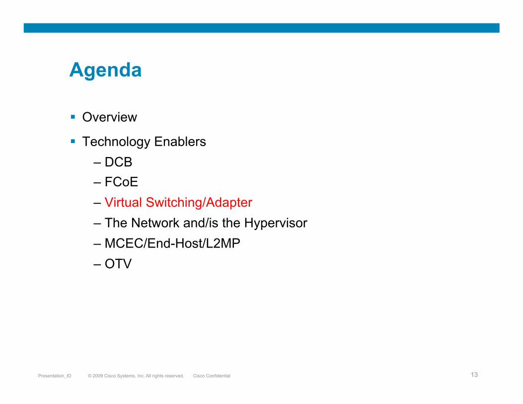
Agenda
Overview
Technology Enablers – DCB – FCoE – Virtual Switching/Adapter – The Network and/is the Hypervisor – MCEC/End-Host/L2MP – OTV

© 2009 Cisco Systems, Inc. All rights reserved. Cisco Confidential Presentation_ID 3
Overview
Assertion: Virtualization is driving technology in the data center – Challenges:
• The obfuscation of the system/network border (Accountability, Security) • The need for rack/row portability • The requirement for L2 adjacency
– Solutions: • Virtual Switching, Virtual Adapters, VN-Tags • Unified Fabrics (FCoE), FabricPath/TRILL • FabricPath/TRILL, OTV

© 2009 Cisco Systems, Inc. All rights reserved. Cisco Confidential Presentation_ID 4
WAN Edge: • 40G/100G • IPoDWDM • OTV
Data Center Core: • Dense Clos, Fully/Mostly Non-Blocking • No STP (L2MP/End Host Mode) • Unified I/O (Data, Storage, HPC)
Compute: • Uniform Resources • Full VM Portability • Scalable Units
Campus LAN WAN SAN/ Parallel FS
Unified and Simplified

© 2009 Cisco Systems, Inc. All rights reserved. Cisco Confidential Presentation_ID 5
Agenda
Overview
Technology Enablers – DCB – FCoE – Virtual Switching/Adapter – The Network and/is the Hypervisor – MCEC/End-Host/L2MP – OTV

© 2009 Cisco Systems, Inc. All rights reserved. Cisco Confidential Presentation_ID 6
Data Center Bridging Features
Enables lossless Fabrics for each class of service PAUSE sent per virtual lane when buffers limit exceeded Network resources are partitioned between VL’s (E.g. input buffer and output queue) The switch behavior is negotiable per VL
Priority-Based Flow Control (PFC)
© 2009 Cisco Systems, Inc. All rights reserved. Cisco Confidential Presentation_ID 7
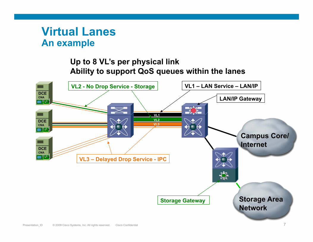
Virtual Lanes An example
VL1 VL2 VL3
LAN/IP Gateway
Storage Gateway
VL1 – LAN Service – LAN/IP
VL3 – Delayed Drop Service - IPC
VL2 - No Drop Service - Storage
Up to 8 VL’s per physical link Ability to support QoS queues within the lanes
DCE CNA
DCE CNA
DCE CNA
Campus Core/ Internet
Storage Area Network

© 2009 Cisco Systems, Inc. All rights reserved. Cisco Confidential Presentation_ID 8
Data Center Ethernet Features
Data Center Bridging eXchange
Handshaking Negotiation for: CoS BW Management Class Based Flow Control Congestion Management (BCN/QCN) Application (user_priority usage) Logical Link Down
Data Center Ethernet
Data Center Ethernet

© 2009 Cisco Systems, Inc. All rights reserved. Cisco Confidential Presentation_ID 9
Enhanced Transmission Selection (ETS)
Enables Intelligent sharing of bandwidth between traffic classes control of bandwidth Being Standardized in IEEE 802.1Qaz Also known as Priority Grouping
Data Center Ethernet Features

© 2009 Cisco Systems, Inc. All rights reserved. Cisco Confidential Presentation_ID 10
Agenda
Overview
Technology Enablers – DCB – FCoE – Virtual Switching/Adapter – The Network and/is the Hypervisor – MCEC/End-Host/L2MP – OTV

© 2009 Cisco Systems, Inc. All rights reserved. Cisco Confidential Presentation_ID 11
Mapping of FC Frames over Ethernet
Enables FC to Run on a Lossless Ethernet Network
Fewer Cables – Both block I/O & Ethernet traffic co-exist on same cable
Fewer adapters needed
Overall less power
Interoperates with existing SAN’s
No Gateway - Stateless
FCoE Benefits
FC over Ethernet (FCoE)
Fibre Channel Traffic
Ethernet

© 2009 Cisco Systems, Inc. All rights reserved. Cisco Confidential Presentation_ID 12
Unified I/O, why the trouble?
Initiator
Target
Edge switch
Edge switch
Edge switch
Core switch
Core switch
Increasing CA
PE
X savings
Spare bandwidth available
The land of ovesubscription. No spare bandwidth
Nothing to unify. No spare bandwidth
© 2009 Cisco Systems, Inc. All rights reserved. Cisco Confidential Presentation_ID 13
Agenda
Overview
Technology Enablers – DCB – FCoE – Virtual Switching/Adapter – The Network and/is the Hypervisor – MCEC/End-Host/L2MP – OTV

© 2009 Cisco Systems, Inc. All rights reserved. Cisco Confidential Presentation_ID 14
Switching for the Virtual World
Hardware Option
Used Virtual Adapters + VN-Tag Policy Follows VM Hypervisor bypass capability Works with multiple hypervisors Deterministic Performance Translates Virtual to Physical
Software Option
Integrated into Hypervisor Policy follows VM Embedded Policy Enforcement Requires Vmware hypervisor Switch-like capabilities e.g.:
Netflow SPAN
VMW ESX"
Server VM #1
VM #4
VM #3
VM #2
NIC" NIC"
LAN
Nexus 1000V
Nexus 1000V VMW ESX!
VM #4
VM #3
Server VM #2
VM #1
Initiator
Nexus 5000

© 2009 Cisco Systems, Inc. All rights reserved. Cisco Confidential Presentation_ID 15
Adapter Offerings
Cost Compatibility Virtualization
PCIe x16
10GbE/FCoE
vNICs
Eth
0
FC
1
QP
2
FC
3
Eth
127
10GbE/FCoE
PCIe Bus
FC 10GbE Software FCoE
“Free” SAN Access for Any Ethernet Equipped Host
Existing Driver Stacks
VM I/O Virtualization and Consolidation

© 2009 Cisco Systems, Inc. All rights reserved. Cisco Confidential Presentation_ID 16
Software Switching VNTag in Hardware VNTag in Hardware with VM
DirectPath
Deployment Options for Virtualized Environments Three Options Available, Invisible to VM

© 2009 Cisco Systems, Inc. All rights reserved. Cisco Confidential Presentation_ID 17
Agenda
Overview
Technology Enablers – DCB – FCoE – Virtual Switching/Adapter – The Network and/is the Hypervisor – MCEC/End-Host/L2MP – OTV

© 2009 Cisco Systems, Inc. All rights reserved. Cisco Confidential Presentation_ID 18
The Network and/is the Hypervisor
Zone 1 Zone 2
VEM Policy Enforcement
VEM
Zone 3
2 Approaches to virtualizing network services:
1. Take physical appliances and virtualize them (e.g. ASA VM)
• Easy to implement
• The Network is the Hypervisor
2. Integrate the physical appliance’s functionality into the hypervisor
• Takes best advantage of the virtualization capabilities
• Highly Scalable/Available
Zone 3
Policy Enforcement

© 2009 Cisco Systems, Inc. All rights reserved. Cisco Confidential Presentation_ID 19
Agenda
Overview
Technology Enablers – DCB – FCoE – Virtual Switching/Adapter – The Network and/is the Hypervisor – MCEC/End-Host/L2MP – OTV

© 2009 Cisco Systems, Inc. All rights reserved. Cisco Confidential Presentation_ID 20
Modern DC: Rich Mesh

© 2009 Cisco Systems, Inc. All rights reserved. Cisco Confidential Presentation_ID 21
Modern DC: After Spanning Tree is Done
We need to go beyond this model

© 2009 Cisco Systems, Inc. All rights reserved. Cisco Confidential Presentation_ID 22
Spanning Tree Alternatives
LAN
Active-Active
MAC B
MAC A
MAC A
MAC B
End-Host Mode
Host Mode Eliminates STP on Uplink Bridge Ports Allows Multiple Active Uplinks Switch to Network Prevents Loops by Pinning a MAC Address to Only One Port Completely Transparent to Next Hop Switch
LAN
L2 ECMP
L2 ECMP
FabricPath/Trill
Uses ISIS based topology Up to 16 way ECMP Eliminates STP from L2 domain Preferred path selection
LAN
vPC/MEC
Multi-Chassis EC
Virtual Switch (VSS on C6K, vPC on Nexus 7K) Virtual port channel mechanism is transparent to hosts or switches connected to the virtual switch STP as fail-safe mechanism to prevent loops even in the case of control plane failure
Virtual Switch

© 2009 Cisco Systems, Inc. All rights reserved. Cisco Confidential Presentation_ID 23
FabricPath Overview
Assign switchIDs to L2MP bridges Compute routes between L2MP bridges using IS-IS
Provides ECMP (equal cost multi-pathing) Learn association of MAC address to switchID Leverage IEEE functions as services (such as VLANs)
L2MP Domain CE Domain CE Domain
A
B
C
D
1 2
3
4 6
5
7
B 4
D L
B L
D 6

© 2009 Cisco Systems, Inc. All rights reserved. Cisco Confidential Presentation_ID 24
Dual-Connect CE Devices to FabricPath vPC+ (a.k.a. Emulated Switch)
On L2MP Edge Switch
vPC is still required to provide active/active L2 path for dual-homed CE devices or clouds
However, L2MP MAC table only allow 1-to-1 mapping between MAC and Switch-ID
Each vPC domain is represented by an unique ‘Emulated Switch’ to the rest of L2MP Core
Switch-ID for each ‘Emulated Switch’ is then used as the Source for MAC-in-MAC encapsulation
L2MP Core
S1 S2
A
B
S3
MAC Table
A ???
MAC Table
B S3 B A Payload
B A Payload S2 S3 B A Payload S1 S3
L2MP Core
S1 S2
B
S3
MAC Table
A S4
MAC Table
B S3
B A Payload A
S4
B A Payload S4 S3 B A Payload S4 S3
vPC vPC+

© 2009 Cisco Systems, Inc. All rights reserved. Cisco Confidential Presentation_ID 25
Connect L3 or Services to L2MP Core L2MP Anycast
Typical L2MP topology is constructed with 2 or more L2MP switches at the aggregation layer
Since FHRP allows only 1 active device for each Gateway-MAC, providing optimal paths for traffic between L2MP Core and L3 network become challenging
The same situation exists when connections to multiple active service nodes are required
Similar to vPC+, the solution is to allow all L2MP Edge switches connecting the same L3 network or service nodes to share a common “Emulated Switch-ID
L3
L2
Layer 3 Network
L2MP Core

© 2009 Cisco Systems, Inc. All rights reserved. Cisco Confidential Presentation_ID 26
Agenda
Overview
Technology Enablers – DCB – FCoE – Virtual Switching/Adapter – The Network and/is the Hypervisor – MCEC/End-Host/L2MP – OTV

© 2009 Cisco Systems, Inc. All rights reserved. Cisco Confidential Presentation_ID 27
Traditional Layer 2 VPNs
EoMPLS
VPLS Dark Fiber

© 2009 Cisco Systems, Inc. All rights reserved. Cisco Confidential Presentation_ID 28
OTV at a Glance Ethernet traffic between sites is encapsulated in IP: “MAC in IP”
Dynamic encapsulation based on MAC routing table
Currently submitted as an IETF draft - http://tools.ietf.org/html/draft-hasmit-otv-00
Communication between MAC1 (site 1) and MAC2 (site 2) Server 1
MAC 1 Server 2 MAC 2
OTV OTV MAC IF
MAC1 Eth1
MAC2 IP B
MAC3 IP B IP A IP B
Encap Decap MAC1 MAC2 IP A IP B MAC1 MAC2 MAC1 MAC2

© 2009 Cisco Systems, Inc. All rights reserved. Cisco Confidential Presentation_ID 29
MAC 2
MAC 1
OTV Data Plane: Unicast
Core
MAC TABLE
VLAN MAC IF 100 MAC 1 Eth 2
100 MAC 2 Eth 1
MAC 4
MAC 3
IP A IP B
Intra-Site Traffic
West East
L2 L3 L3 L2
Ani
mat
ed S
lide
! Layer 2
Lookup
Eth 1
Eth 2
Eth 1
Eth 2
MAC 1 MAC 2

© 2009 Cisco Systems, Inc. All rights reserved. Cisco Confidential Presentation_ID 30
Eth 4
Eth 3
MAC TABLE
VLAN MAC IF 100 MAC 1 Eth 2
100 MAC 2 Eth 1
100 MAC 3 IP B
100 MAC 4 IP B
MAC 2
MAC 1
OTV Data Plane: Unicast
Core
MAC 4
MAC 3
External IP A
External IP B
West East
L2 L3 L3 L2
Ani
mat
ed S
lide
!
OTV Inter-Site Traffic
MAC Table contains MAC addresses reachable through
IP addresses
Encap 2
Layer 2 Lookup
1
No Pseudo-Wire state is maintained.
The encapsulation is done based on a Layer 2 destination lookup.
3 Decap 4 MAC 1 MAC 3
6
MAC TABLE
VLAN MAC IF 100 MAC 1 IP A
100 MAC 2 IP A
100 MAC 3 Eth 3
100 MAC 4 Eth 4
Eth 1
Eth 2
Layer 2 Lookup
5
MAC 1 MAC 3
IP A IP B MAC 1 MAC 3 MAC 1 MAC 3 IP A IP B MAC 1 MAC 3

© 2009 Cisco Systems, Inc. All rights reserved. Cisco Confidential Presentation_ID 31
Multi-Homing: Loop Condition Handling
OTV includes the logic necessary to avoid the creation of loops in multi-homed site scenarios.
Each site will have its own STP domain, which is separate and independent from the STP domains in other sites, even though all sites will be part of common Layer 2 domain.
Core
STP domain 1
STP domain 2
No STP

© 2009 Cisco Systems, Inc. All rights reserved. Cisco Confidential Presentation_ID 32
Authoritative Edge Device
OTV provides loop-free multi-homing by electing a designated forwarding device per site for each VLAN.
The designated forwarder is referred to as the Authoritative Edge Device (AED).
The Edge Devices at the site peer with each other on the internal interfaces to elect the AED
The AED is the only edge device that will forward multicast and broadcast traffic between a site and the overlay.
Core
AED AED

© 2009 Cisco Systems, Inc. All rights reserved. Cisco Confidential Presentation_ID 33
Q and A

© 2009 Cisco Systems, Inc. All rights reserved. Cisco Confidential Presentation_ID 34
Cisco