Nexans GPH - Mechanical Connectors & Cable Lugs (Catalogue)
24
Schraubverbinder Schraubkabelschuhe Katalog D Mechanical Connectors Mechanical Cable Lugs Catalog D Nexans Power Accessories Germany GmbH Ferdinand-Porsche-Str. 12 95028 Hof/Saale Telefon +49 (0)92 81 83 060 Postfach 1406 95013 Hof/Saale Telefax +49 (0)92 81 83 0630 http://www.nexans-power-accessories.com e-mail: [email protected]
-
Upload
thorne-derrick-uk-low-high-voltage-power-cabling-jointing-hazardous-area-electrical-eqpt -
Category
Business
-
view
706 -
download
15
description
The first generation of “GPH Single Shear Off Technology” allowed precision and consistent contact force with which the conductor is installed into the barrel of the mechanical connector providing: • a simple and fail safe solution without use of special tools • a connection that guaranteed the correct contact force within the barrel by shearing off the hexagon head at the correct torque level every time • optimized contact regardless of the cable type or make-up e.g. solid, stranded, compacted, round or sector • suitability for a wide cross sectional range of conductors The second generation of “GPH Double Shear Off Technology” using an Allen Key for a 2 Step installation providing suitability for a wider cross sectional range of conductors. Further development for medium voltage applications required reduction of “excess length” of shear off bolts. The third generation of “GPH Multi Share Off Bolt Technology” once again improved the technical performance. This design was patented in 1998 and is used in all GPH M- and C - Series products. Market demand, to reduce stock cost, drove the need to widen the cross section range. This brought new challenges into the design of mechanical connectors when considering the minimum and maximum range of a particular shear bolt and the management of excess length of the shear bolt itself. It is physically intuitive that small cross sections should be connected with lower forces than larger ones. Exposing small conductors to high contact forces causes inevitable partial cross section reduction.
Transcript of Nexans GPH - Mechanical Connectors & Cable Lugs (Catalogue)
SchraubverbinderSchraubkabelschuhe
Katalog D
Mechanical ConnectorsMechanical Cable Lugs
Catalog D
Nexans Power Accessories Germany GmbHFerdinand-Porsche-Str. 12 95028 Hof/Saale Telefon +49 (0)9281 83060Postfach 1406 95013 Hof/Saale Telefax +49 (0)9281 830630http://www.nexans-power-accessories.com e-mail: [email protected]
Endbundklemmen
Mehrzweckklemmen
Endabspannklemmen
Abzweigklemmen
Schlitzklemmen
ISO-Abzweigklemmen
Kerbverbinder
Pressverbinder
Reduzierhülsen
Schraubverbinder
Schraubkabelschuhe
Direktanschlussklemmen
Presskabelschuhe
Cupalscheiben
Klemmkabelschuhe
Endverschlussbolzen
Pressanschlüsse
Werkzeuge
Kontakt Fett
Dead-End Clamps
Universal Overhead Line Clamps
Dead-End Clamps Cone-type
Parallel Grove Clamps
Split Bolt Connectors
ISO-Tap-off clamps
Notch Type Midspan Joints
Compression Joints
Reduction Sleeves
Mechanical Connectors
Mechanical Cable Lugs
Terminal Clamps
Compression Cable Lugs
Cupaldisks
Cable Lugs Clamping-type
End-Compression Terminal Pin-type
Compression Terminal Pin-type
Tools
Contact Grease
Nexans Power Accessories Germany GmbHFerdinand-Porsche-Str. 12 95028 Hof/Saale Telefon +49 (0)9281 83060Postfach 1406 95013 Hof/Saale Telefax +49 (0)9281 830630http://www.nexans-power-accessories.com e-mail: [email protected]
Pamela Kinnell
Address Stamp

Der Nachdruck dieses Katalogs ist, auch auszugsweise, nur mit besonde-rer Erlaubnis gestattet.
Die angegebenen Daten wurden gewissenhaft ermittelt, sie geben jedochnur Richtwerte an und befreien Sie nicht von der eigenen Prüfung der vonuns gelieferten Produkte auf ihre Eignung für die beabsichtigten Zwecke.Verarbeitung und Anwendung der Produkte erfolgen außerhalb unsererKontrollmöglichkeit und liegen daher ausschließlich in Ihrem Verantwor-tungsbereich.
Die Abbildungen und Zeichnungen sind nicht unbedingt maßgebend. DieGewichtsangaben sind annähernd und schließen die Kartonverpackungmit ein. Nach Möglichkeit sind nur komplette Normalverpackungen zubestellen.
Das Verbindungsmaterial wird vorwiegend in Kartons verpackt geliefert.Wir verwenden nur recyclingfähige Verpackungsmaterialien nach derneuen Verpackungsordnung. Faltkartons werden nicht zurückgenommen.
Änderungen bleiben uns ausdrücklich vorbehalten. Mit diesem Katalogwerden frühere Ausgaben ungültig.
Unsere Erzeugnisse entsprechen den einschlägigen VDE-Bestimmungen,bzw. - soweit erschienen - den entsprechenden DIN-Blättern und IEC-Empfehlungen.
Unsere Geschäftsbedingungen entsprechen der jeweils neuesten Ausgabeder "Allgemeinen Lieferbedingungen für Erzeugnisse und Leistungen derElektroindustrie". Auf Wunsch senden wir Ihnen eine Kopie zu.
Ausführungen, die nicht im Katalog enthalten sind, erhalten Sie auf An-frage.
Hof, im Februar 2010
Reprinting, even partial, only with special allowance.
The data given were determined diligently, they are however only guidevalues and do not release our customers of the duty to carry out teststhemselves in order to check the suitability of the products delivered by usfor the intended use.Processing and use of the products cannot be controlled by us and aretherefore exclusively in your field of responsibility.
Illustrations and drawings may only show a close reflection and are notdecisive. The weights are approximate and include the carton package.Our products are mainly delivered in cartons. Please try to order completestandard packages.
We only use package materials able to be recycled due to the latest pak-king system.Collapsible cardboard boxes are not taken back.
We reserve the right to alter or modify the characteristics described.This catalogue substitutes all former editions.
Our products meet the VDE standards respectively correspond to DINpages and IEC recommendations.
Our responsibilities are only those listed in the latest edition of “GeneralTerms and Conditions for the Supply of Products and Services of the Elec-trical and Electronics Industry”. If requested we provide a copy.
Types or versions not part of the catalogue you receive on request.
Hof, February 2010
Mechanical ConnectorsMechanical Cable Lugs
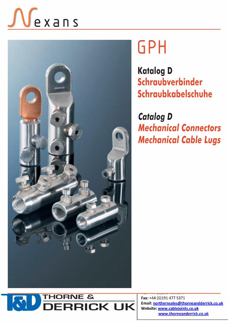
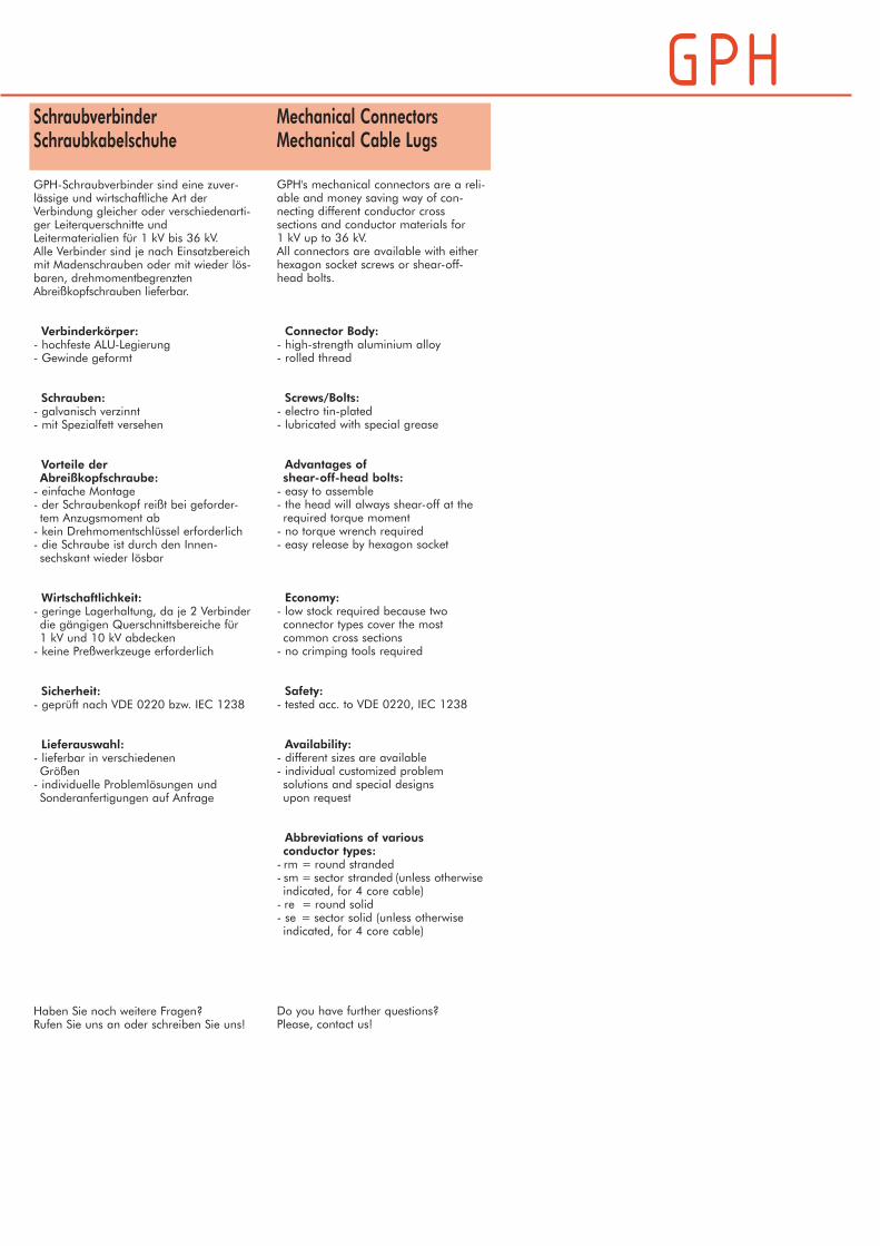
GPH's mechanical connectors are a reli-able and money saving way of con-necting different conductor crosssections and conductor materials for1 kV up to 36 kV.All connectors are available with eitherhexagon socket screws or shear-off-head bolts.
Connector Body:- high-strength aluminium alloy- rolled thread
Screws/Bolts:- electro tin-plated- lubricated with special grease
Advantages ofshear-off-head bolts:- easy to assemble- the head will always shear-off at therequired torque moment- no torque wrench required- easy release by hexagon socket
Economy:- low stock required because twoconnector types cover the mostcommon cross sections- no crimping tools required
Safety:- tested acc. to VDE 0220, IEC 1238
Availability:- different sizes are available- individual customized problemsolutions and special designsupon request
Abbreviations of variousconductor types:- rm = round stranded- sm = sector stranded (unless otherwiseindicated, for 4 core cable)- re = round solid- se = sector solid (unless otherwiseindicated, for 4 core cable)
Do you have further questions?Please, contact us!
SchraubverbinderSchraubkabelschuhe
GPH-Schraubverbinder sind eine zuver-lässige und wirtschaftliche Art derVerbindung gleicher oder verschiedenarti-ger Leiterquerschnitte undLeitermaterialien für 1 kV bis 36 kV.Alle Verbinder sind je nach Einsatzbereichmit Madenschrauben oder mit wieder lös-baren, drehmomentbegrenztenAbreißkopfschrauben lieferbar.
Verbinderkörper:- hochfeste ALU-Legierung- Gewinde geformt
Schrauben:- galvanisch verzinnt- mit Spezialfett versehen
Vorteile derAbreißkopfschraube:- einfache Montage- der Schraubenkopf reißt bei geforder-tem Anzugsmoment ab- kein Drehmomentschlüssel erforderlich- die Schraube ist durch den Innen-sechskant wieder lösbar
Wirtschaftlichkeit:- geringe Lagerhaltung, da je 2 Verbinderdie gängigen Querschnittsbereiche für1 kV und 10 kV abdecken- keine Preßwerkzeuge erforderlich
Sicherheit:- geprüft nach VDE 0220 bzw. IEC 1238
Lieferauswahl:- lieferbar in verschiedenenGrößen- individuelle Problemlösungen undSonderanfertigungen auf Anfrage
Haben Sie noch weitere Fragen?Rufen Sie uns an oder schreiben Sie uns!
D-1
Tabellarische Übersicht der Klemmbereicheund Inhaltsverzeichnis
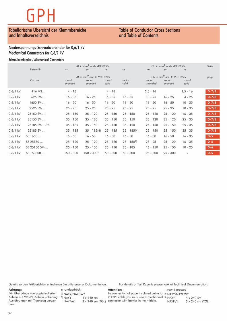
Niederspannungs-Schraubverbinder für 0,6/1 kVMechanical Connectors for 0,6/1 kV
Table of Conductor Cross Sectionsand Table of Contents
AL in mm2 nach VDE 0295 CU in mm2 nach VDE 0295 SeiteListen-Nr. rm sm re se rm sm re
AL in mm2 acc. to VDE 0295 CU in mm2 acc. to VDE 0295 pageCat. no. round sector round sector round sector round
stranded stranded solid solid stranded stranded solid
Schraubverbinder / Mechanical Connectors
0,6/1 kV 416 MS... 4 - 16 4 - 16 2,5 - 16 2,5 - 16 D-7/8
0,6/1 kV 625 SV-... 16 - 35 16 - 25 6 - 35 16 - 35 10 - 25 16 - 25 4 - 25 D-7/8
0,6/1 kV 1650 SV-... 16 - 50 16 - 50 16 - 50 16 - 50 16 - 50 16 - 50 10 - 35 D-7/8
0,6/1 kV 2595 SV-... 25 - 95 25 - 95 25 - 95 25 - 95 25 - 95 25 - 95 10 - 35 D-7/8
0,6/1 kV 25150 SV-... 25 - 150 25 - 120 25 - 150 25 - 150 25 - 120 25 - 120 16 - 35 D-7/8
0,6/1 kV 35150 SV-... 35 - 150 35 - 120 35 - 150 35 - 150 35 - 120 35 - 120 25 - 35 D-7/8
0,6/1 kV 25185 SV-... 32 35 - 185 35 - 150 25 - 150 35 - 150 25 - 150 25 - 150 25 - 35 D-7/8
0,6/1 kV 25185 SV-... 35 - 185 35 - 185(4) 25 - 185 35 - 185(4) 25 - 150 25 - 150 25 - 35 D-7/8
0,6/1 kV SE 1650... 16 - 50 16 - 50 16 - 50 16 - 50 16 - 50 16 - 50 16 - 35 D-5
0,6/1 kV SE 25150 ... 25 - 120 25 - 120 25 - 120 25 - 1502) 25 - 95 25 - 120 16 - 35 D-5
0,6/1 kV SE 25150 SM-... 25 - 150 25 - 150 25 - 150 25 - 185 16 - 150 25 - 150 10 - 25 D-6
0,6/1 kV SE 150300 ... 150 - 300 150 - 3003) 150 - 300 150 - 300 95 - 300 95 - 300 - D-5
Details zu den Prüfberichten entnehmen Sie bitte unserer Dokumentation.
Achtung:Für Übergänge von papierisoliertenKabeln auf VPE/PE-Kabeln unbedingtAusführungen mit Trennsteg verwen-den.
Attention:By connection of paperinsulated cable toVPE/PE cable you must use a mechanicalconnector with barrier in the middle.
1) rundgedrückt2) NAYY/NAYCWY3) NAYY 4 x 240 smNAYFaY 3 x 240 sm (TGL)
1) round pressed2) NAYY/NAYCWY3) NAYY 4 x 240 smNAYFaY 3 x 240 sm (TGL)
For details of Test Reports please look at Technical Documentation.

D- 2
AL in mm2 CU in mm2 SeiteListen-Nr. rm(v) re sm rm(v) sm
AL in mm2 CU in mm2 pageCat. no. round round sector round sector
stranded solid stranded stranded stranded
Tabellarische Übersicht der Klemmbereicheund Inhaltsverzeichnis
Table of Conductor Cross Sectionsand Table of Contents
Mittelspannungs-Schraubverbinder und Kabelschuh für 18/30 kVMechanical Connectors and Cable Lugs for 18/30 kVZentrische Schraubverbinder mit Mehrfach-Abreißkopfschraube / Centric Mechanical Connectors with Shear-Off-Head-Bolts
Die in diesen Tabellen erfolgten Zuordnungen sind nur ein Anhaltspunkt, denn bei der in den heutigen Netzen vorhandenen Kabelvielfalt sind Leiter glei-chen Nennquerschnittes oft ganz unterschiedlich aufgebaut. Daher hält GPH vor der Einführung von Schraubverbindern ein technisches Beratungsgesprächfür unbedingt erforderlich!
Due to the huge variety of conductors with different structures, this table of correspondence is only indicative. Therefore GPH provides detailed technicalinformation on mechanical connectors with regard to conductors used in the customer´s table network. This consultation is absolutely necessary prior to anyintroduction of mechanical connectors.
M 16 - 95 16 - 95 16 - 50/95 25 - 70 16 - 95 25 - 70 D-11
M 50 - 150 50 - 150 50 - 150 50 - 120 35 - 120 50 - 120 D-11
M 50 - 150 / 16 - 95 1. Seite / side 50 - 150 50 - 150 50 - 120 35 - 120 50 - 120 D-11
2. Seite / side 16 - 95 10 - 95 25 - 70 10 - 70 25 - 70
M 70 - 240 70 - 240 70 - 240 70 - 240 70 - 240 70 - 240 D-11
M 95 - 240 95 - 240 95 - 240 95 - 185 95 - 240 95 - 185 D-11
M 95 - 240 / 16 - 95 1. Seite / side 95 - 240 95 - 240 95 - 185 95 - 240 95 - 185 D-11
2. Seite / side 16 - 95 10 - 95 25 - 70 10 - 70 25 - 70
M 120 - 300 120 - 300 120 - 300 120 - 240 120 - 300 120 - 240 D-11
M 120 - 300 / 16 - 95 1. Seite / side 120 - 300 120 - 300 120 - 240 120 - 300 120 - 240 D-11
2. Seite / side 16 - 95 10 - 95 25 - 70 10 - 70 25 - 70
M 120 - 300 / 95 - 240 1. Seite / side 120 - 300 120 - 300 120 - 240 120 - 300 120 - 240 D-11
2. Seite / side 95 - 240 95 - 240 95 - 185 95 - 240 95 - 185
M 185 - 400 185 - 400 185 - 240/400 185 - 300 185 - 400 185 - 300 D-11
M 185 - 400 / 95 - 240 1. Seite / side 185 - 400 185 - 240/400 185 - 300 185 - 400 185 - 300 D-11
2. Seite / side 95 - 240 95 - 240 95 - 185 95 - 240 95 - 185
M 300 - 500 300 - 500 300 - 500 300 - 400 300 - 500 300 - 400 D-11
M 400 - 630 400 - 630 400 - 630 400 - 500 400 - 630 400 - 500 D-11
M 400 - 630 / 120 - 300 1. Seite / side 400 - 630 400 - 630 400 - 500 400 - 630 400 - 500 D-11
2. Seite / side 120 - 300 120 - 300 120 - 240 120 - 300 120 - 240
MRL 95 - 240 95 - 240 95 - 240 95 - 240 95 - 185 95 - 185 D-12
MRLT 95 - 240 95 - 240 95 - 240 95 - 2401) 95 - 185 95 - 185 D-12
MRLT 95 - 240 / 16 - 95 1. Seite / side 95 - 240 95 - 240 95 - 2401) 95 - 185 95 - 185 D-12
2. Seite / side 16 - 95 10 - 95 25 - 70 10 - 70 25 - 70
SB70-240 70 - 240 70 - 240 70 - 240 70 - 240 70 - 240 D-13
SB120-300 120 - 300 120 - 300 120 - 240 120 - 300 120 - 240 D-13
SB185-400 185 - 400 185 - 240/400 185 - 300 185 - 400 185 - 300 D-13
D-3
Tabellarische Übersicht der Klemmbereicheund Inhaltsverzeichnis
Table of Conductor Cross Sectionsand Table of Contents
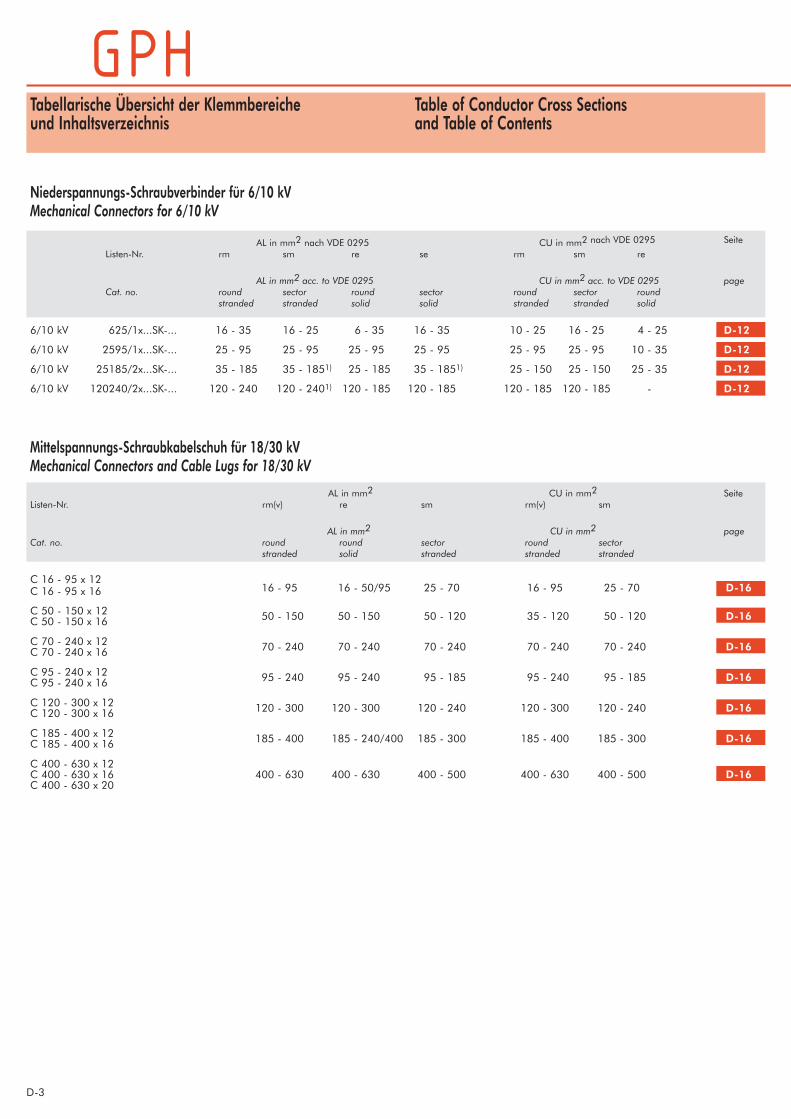
Niederspannungs-Schraubverbinder für 6/10 kVMechanical Connectors for 6/10 kV
AL in mm2 nach VDE 0295 CU in mm2 nach VDE 0295 Seite
Listen-Nr. rm sm re se rm sm re
AL in mm2 acc. to VDE 0295 CU in mm2 acc. to VDE 0295 pageCat. no. round sector round sector round sector round
stranded stranded solid solid stranded stranded solid
6/10 kV 625/1x...SK-... 16 - 35 16 - 25 6 - 35 16 - 35 10 - 25 16 - 25 4 - 25 D-12
6/10 kV 2595/1x...SK-... 25 - 95 25 - 95 25 - 95 25 - 95 25 - 95 25 - 95 10 - 35 D-12
6/10 kV 25185/2x...SK-... 35 - 185 35 - 1851) 25 - 185 35 - 1851) 25 - 150 25 - 150 25 - 35 D-12
6/10 kV 120240/2x...SK-... 120 - 240 120 - 2401) 120 - 185 120 - 185 120 - 185 120 - 185 - D-12
Mittelspannungs-Schraubkabelschuh für 18/30 kVMechanical Connectors and Cable Lugs for 18/30 kV
C 16 - 95 x 12C 16 - 95 x 16 16 - 95 16 - 50/95 25 - 70 16 - 95 25 - 70 D-16
C 50 - 150 x 12 50 - 150 50 - 150 50 - 120 35 - 120 50 - 120 D-16C 50 - 150 x 16
C 70 - 240 x 12 70 - 240 70 - 240 70 - 240 70 - 240 70 - 240 D-16C 70 - 240 x 16
C 95 - 240 x 12 95 - 240 95 - 240 95 - 185 95 - 240 95 - 185 D-16C 95 - 240 x 16
C 120 - 300 x 12 120 - 300 120 - 300 120 - 240 120 - 300 120 - 240 D-16C 120 - 300 x 16
C 185 - 400 x 12 185 - 400 185 - 240/400 185 - 300 185 - 400 185 - 300 D-16C 185 - 400 x 16
C 400 - 630 x 12C 400 - 630 x 16 400 - 630 400 - 630 400 - 500 400 - 630 400 - 500 D-16C 400 - 630 x 20
AL in mm2 CU in mm2 SeiteListen-Nr. rm(v) re sm rm(v) sm
AL in mm2 CU in mm2 pageCat. no. round round sector round sector
stranded solid stranded stranded stranded

D- 4
SchirmdrahtScreen Wire
Die in diesen Tabellen erfolgten Zuordnungen sind nur ein Anhaltspunkt, denn bei der in den heutigen Netzen vorhandenen Kabelvielfalt sind Leitergleichen Nennquerschnittes oft ganz unterschiedlich aufgebaut. Daher hält GPH vor der Einführung von Schraubverbindern ein technischesBeratungsgespräch für unbedingt erforderlich!
Due to the huge variety of conductors with different structures, this table of correspondence is only indicative. Therefore GPH provides detailed technicalinformation on mechanical connectors with regard to conductors used in the customer´s table network. This consultation is absolutely necessary prior toany introduction of mechanical connectors.
1) rundgedrückt 1) round pressed
Cu in mm2 Flachdraht Al SeiteAnzahl Maß
Listen-Nr.
Cu in mm2 Flat wire Al pagequantity Dimension
Cat. no.
Schirmdrahtverbinder / Screen Wire Connector:
1070 MS 10-50 3-13 1 mm x 5,2 mm D-11
Schirmdrahtkabelschuhe / Screen Wire Lug:
1070/1 x ... MS 10-50 3-13 1 mm x 5,2 mm D-11
Tabellarische Übersicht der Klemmbereicheund Inhaltsverzeichnis
Table of Conductor Cross Sectionsand Table of Contents

D-5
SSEE 2255115500 TT--VV--KK SSEE 115500330000 VV--KK
Mechanical Connector 0,6/1 kVwith 2 or 4shear-off-head boltsconductor barrel with longitudinal andtransvers groovings
Materials:Connector Body: high strength
aluminium alloy Bolts: brass, tin-plated
hexagon see installationinstruction
Surface:SE ... K:Connector Body: uncoated
SE ... V-K:Connector Body: tin-plated
SE ... V-I-K:Connector Body: tin-plated
partially insulated
Connector Body:SE ...: without oil stopSE ... T- ...: with oil stop
Schraubverbinder 0,6/1 kV mit 2 oder 4AbreißkopfschraubenLeiterbohrung mit Quer- und Längsrillen
Werkstoff:Verbinderkörper: Alu-Legierung
Schrauben: Messing, galvanisch verzinntSW s. Montageanweisung
Oberfläche:SE ... K:Verbinderkörper: blank
SE ... V-K:Verbinderkörper: galvanisch verzinnt
SE ... V-I-K:Verbinderkörper: galvanisch verzinnt
und teilisoliert
Verbinderkörper:SE ...: ohne TrennstegSE ... T- ...: mit Trennsteg
SE 1650 MS-V-K * 16-50 16-50 16-50 16-50 16-50 16-50 16-35 40 18,5
SE 1650 T-V-K 16-50 16-50 16-50 16-50 16-50 16-50 16-35 40 18,5
SE 25150 K SE 25150 V-K 25-120 25-120 25-120 25-150 25-95 25-120 16-35 70 26,5
SE 25150 T-K SE 25150 T-V-K 25-120 25-120 25-120 25-150 25-95 25-120 16-35 70 26,5
SE 25150 T-V-I-K 25-120 25-120 25-120 25-150 25-95 25-120 16-35 75 31,5
SE 150300 K SE 150300 V-K 150-300 150-300 150-300 150-300 95-300 95-300 - 110 38,0
SE 150300 T-K SE 150300 T-V-K 150-300 150-300 150-300 150-300 95-300 95-300 - 120 38,0
*) Verbinderkörper: Messing *) Connector Body: brass
Hinweis: Für die Verbindungen von AL- und Cu- bzw. Cu- und Cu-Kabel empfehlen wir die verzinnte Ausführung.
Notice: For the connection of Al- to Cu- and Cu- to Cu-cables werecommend the application of tin-plated connectors.
blank verzinnt Al in mm2 nach VDE 0295 Cu in mm2 nach VDE 0295 Maße in mmrm sm re se rm sm re L D
Listen-Nr.
uncoated tin-plated Al in mm2 acc. VDE 0295 Cu in mm2 acc. VDE 0295 Dimensions in mmround sector round sector round sector round L D
Cat. no. stranded stranded solid solid stranded stranded solid
D- 6
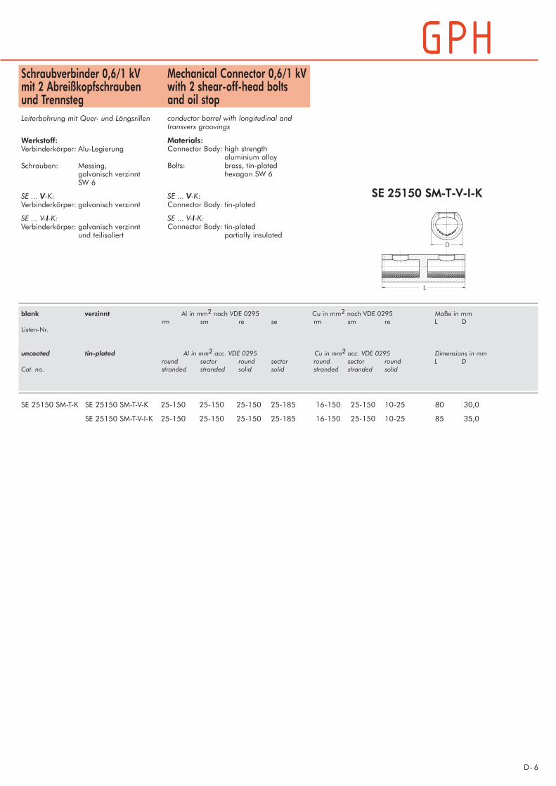
Mechanical Connector 0,6/1 kVwith 2 shear-off-head boltsand oil stopconductor barrel with longitudinal andtransvers groovings
Materials:Connector Body: high strength
aluminium alloy Bolts: brass, tin-plated
hexagon SW 6
SE ... V-K:Connector Body: tin-plated
SE ... V-I-K:Connector Body: tin-plated
partially insulated
Schraubverbinder 0,6/1 kV mit 2 Abreißkopfschraubenund TrennstegLeiterbohrung mit Quer- und Längsrillen
Werkstoff:Verbinderkörper: Alu-Legierung
Schrauben: Messing, galvanisch verzinntSW 6
SE ... V-K:Verbinderkörper: galvanisch verzinnt
SE ... V-I-K:Verbinderkörper: galvanisch verzinnt
und teilisoliert
SSEE 2255115500 SSMM--TT--VV--II--KK
blank verzinnt Al in mm2 nach VDE 0295 Cu in mm2 nach VDE 0295 Maße in mmrm sm re se rm sm re L D
Listen-Nr.
uncoated tin-plated Al in mm2 acc. VDE 0295 Cu in mm2 acc. VDE 0295 Dimensions in mmround sector round sector round sector round L D
Cat. no. stranded stranded solid solid stranded stranded solid
SE 25150 SM-T-K SE 25150 SM-T-V-K 25-150 25-150 25-150 25-185 16-150 25-150 10-25 80 30,0
SE 25150 SM-T-V-I-K 25-150 25-150 25-150 25-185 16-150 25-150 10-25 85 35,0

D-7
662255 SSVV--SS--VV 2255115500 SSVV--VV--KK
blank verzinnt Al in mm2 nach VDE 0295 Cu in mm2 nach VDE 0295 Maße in mm Drehmoment SWrm sm re se rm sm re L D d Nm Sechskant
Listen-Nr. außen/innen
uncoated tin-plated Al in mm2 acc. to VDE 0295 Cu in mm2 acc. to VDE 0295 Dimensions mm Torque Width across flat/round sector round sector round sector round L D d moment hexagon socket
Cat. no. stranded stranded solid solid stranded stranded solid in Nm
416 MS-S-V 4-16 2,5-16 2,5-16 40 12 6,7 3 - / SW 3
416 MS-S-V-K 4-16 2,5-16 2,5-16 40 12 6,7 SW 8 / -
625 SV 625 SV-V 16-35 16-25 6-35 16-35 10-25 16-25 4-25 40 17 9,4 6 - / SW 4
625 SV-S 625 SV-S-V 16-35 16-25 6-35 16-35 10-25 16-25 4-25 40 17 9,4 - / SW 4
625 SV-S-K 625 SV-S-V-K 16-35 16-25 6-35 16-35 10-25 16-25 4-25 40 17 9,4 SW 10 / -
1650 SV-S 1650 SV-S-V 16-50 16-50 16-50 16-50 16-50 16-50 10-35 55 21 11 12 - / SW 5
1650 SV-S-K 1650 SV-S-V-K 16-50 16-50 16-50 16-50 16-50 16-50 10-35 55 21 11 SW 13 / SW 5
2595 SV 2595 SV-V 25-95 25-95 25-95 25-95 25-95 25-95 10-35 55 25 14 12 - / SW 5
2595 SV-S 2595 SV-S-V 25-95 25-95 25-95 25-95 25-95 25-95 10-35 55 25 14 12 - / SW 5
2595 SV-S-K 2595 SV-S-V-K 25-95 25-95 25-95 25-95 25-95 25-95 10-35 55 25 14 SW 13 / SW 5
25150 SV-K 25150 SV-V-K 25-150 25-120 25-150 25-150 25-120 25-120 16-35 70 28 17,5 SW 17 / SW 6
35150 SV-K 35150 SV-V-K 35-150 35-120 35-150 35-150 35-120 35-120 25-35 70 28 17,5 SW 17 / -
25185 SV 25185 SV-V 35-185 35-185 25-185 35-185 25-150 25-150 25-35 80 35 21 20 - / SW 6
25185 SV-K 25185 SV-V-K 35-185 35-185 25-185 35-185 25-150 25-150 25-35 80 35 21 SW 19 / SW 6
25185 SV-32 25185 SV-V 32 35-185 35-150 25-150 35-150 25-150 25-150 25-35 80 32 21 20 - / SW 6
25185 SV-K 32 25185 SV-V-K 32 35-185 35-150 25-150 35-150 25-150 25-150 25-35 80 32 21 SW 19 / SW 6
25185 SV-S 32 25185 SV-S-V 32 35-185 35-150 25-150 35-150 25-150 25-150 25-35 80 32 21 20 - / SW 6
25185 SV-S-K 32 25185 SV-S-V-K 32 35-185 35-150 25-150 35-150 25-150 25-150 25-35 80 32 21 SW 19 / SW 6
Mechanical Connector 0,6/1 kVwith 2 hexagon socket screws or 2 shear-off-head boltsMaterial:SV-...:Connector Body: high strength
aluminium alloyMS-...:Connector Body: brassBolts: brass, tin-plated
Surface:SV-...:Connector Body: uncoated
SV-V-...:Connector Body: tin-plated
Screws:SV-...: with 2 hexagon socket
screwsSV-K-...: with 2 shear-off-head-bolts
Connector Body:SV-S-...: inspection hole in the middle
of the connector body
Schraubverbinder 0,6/1 kV mit 2 Madenschrauben oder 2 AbreißkopfschraubenWerkstoff:SV-...:Verbinderkörper: Alu-LegierungMS-...:Verbinderkörper: MessingSchrauben: Messing,
galvanisch verzinnt
Oberfläche:SV-...:Verbinderkörper: blank
SV-V-...:Verbinderkörper: galvanisch verzinnt
Schrauben:SV-...: mit 2 MadenschraubenSV-K-...: mit 2 Abreißkopf-
schrauben
Verbinderkörper:SV-S-...: Sichtloch quer zur
Leiterbohrung
D- 8
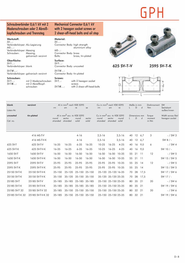
662255 SSVV--TT--VV 22559955 SSVV--TT--KK
Mechanical Connector 0,6/1 kVwith 2 hexagon socket screws or 2 shear-off-head bolts and oil stop
Material:SV-...:Connector Body: high strength
aluminium alloyMS-..:Connector Body: brassBolts: brass, tin-plated
Surface:SV-T-...:Connector Body: uncoated
SV-T-V-...:Connector Body: tin-plated
Screws:SV-T...: with 2 hexagon socket
screwsSV-T-K-...: with 2 shear-off-head-bolts
Schraubverbinder 0,6/1 kV mit 2Madenschrauben oder 2 Abreiß-kopfschrauben und Trennsteg
Werkstoff:SV-...:Verbinderkörper: Alu-LegierungMS-...:Verbinderkörper: MessingSchrauben: Messing,
galvanisch verzinnt
Oberfläche:SV-T-...:Verbinderkörper: blank
SV-T-V-...:Verbinderkörper: galvanisch verzinnt
Schrauben:SV-T-...: mit 2 MadenschraubenSV-T-K-...: mit 2 Abreißkopf-
schrauben
blank verzinnt Al in mm2 nach VDE 0295 Cu in mm2 nach VDE 0295 Maße in mm Drehmoment SWrm sm re se rm sm re L D d Nm Sechskant
Listen-Nr. außen/innen
uncoated tin-plated Al in mm2 acc. to VDE 0295 Cu in mm2 acc. to VDE 0295 Dimensions mm Torque Width across flat/round sector round sector round sector round L D d moment hexagon socket
Cat. no. stranded stranded solid solid stranded stranded solid in Nm
416 MS-T-V 4-16 2,5-16 2,5-16 40 12 6,7 3 - / SW 3
416 MS-T-V-K 4-16 2,5-16 2,5-16 40 12 6,7 SW 8 / -
625 SV-T 625 SV-T-V 16-35 16-25 6-35 16-35 10-25 16-25 4-25 40 16 9,0 6 - / SW 4
625 SV-T-K 625 SV-T-V-K 16-35 16-25 6-35 16-35 10-25 16-25 4-25 40 16 9,0 SW 10 / -
1650 SV-T 1650 SV-T-V 16-50 16-50 16-50 16-50 16-50 16-50 10-35 55 21 11 12 - / SW 5
1650 SV-T-K 1650 SV-T-V-K 16-50 16-50 16-50 16-50 16-50 16-50 10-35 55 21 11 SW 13 / SW 5
2595 SV-T 2595 SV-T-V 25-95 25-95 25-95 25-95 25-95 25-95 10-35 55 25 14 12 - / SW 5
2595 SV-T-K 2595 SV-T-V-K 25-95 25-95 25-95 25-95 25-95 25-95 10-35 55 25 14 SW 13 / SW 5
25150 SV-T-K 25150 SV-T-V-K 25-150 25-120 25-150 25-150 25-120 25-120 16-35 70 28 17,5 SW 17 / SW 6
35150 SV-T-K 35150 SV-T-V-K 35-150 35-120 35-150 35-150 35-120 35-120 25-35 70 28 17,5 SW 17 / -
25185 SV-T 25185 SV-T-V 35-185 35-185 25-185 35-185 25-150 25-150 25-35 80 35 21 20 - / SW 6
25185 SV-T-K 25185 SV-T-V-K 35-185 35-185 25-185 35-185 25-150 25-150 25-35 80 35 21 SW 19 / SW 6
25185 SV-T 32 25185 SV-T-V 32 35-185 35-150 25-150 35-150 25-150 25-150 25-35 80 32 21 20 - / SW 6
25185 SV-T-K 32 25185 SV-T-V-K 32 35-185 35-150 25-150 35-150 25-150 25-150 25-35 80 32 21 SW 19 / SW 6
D-9
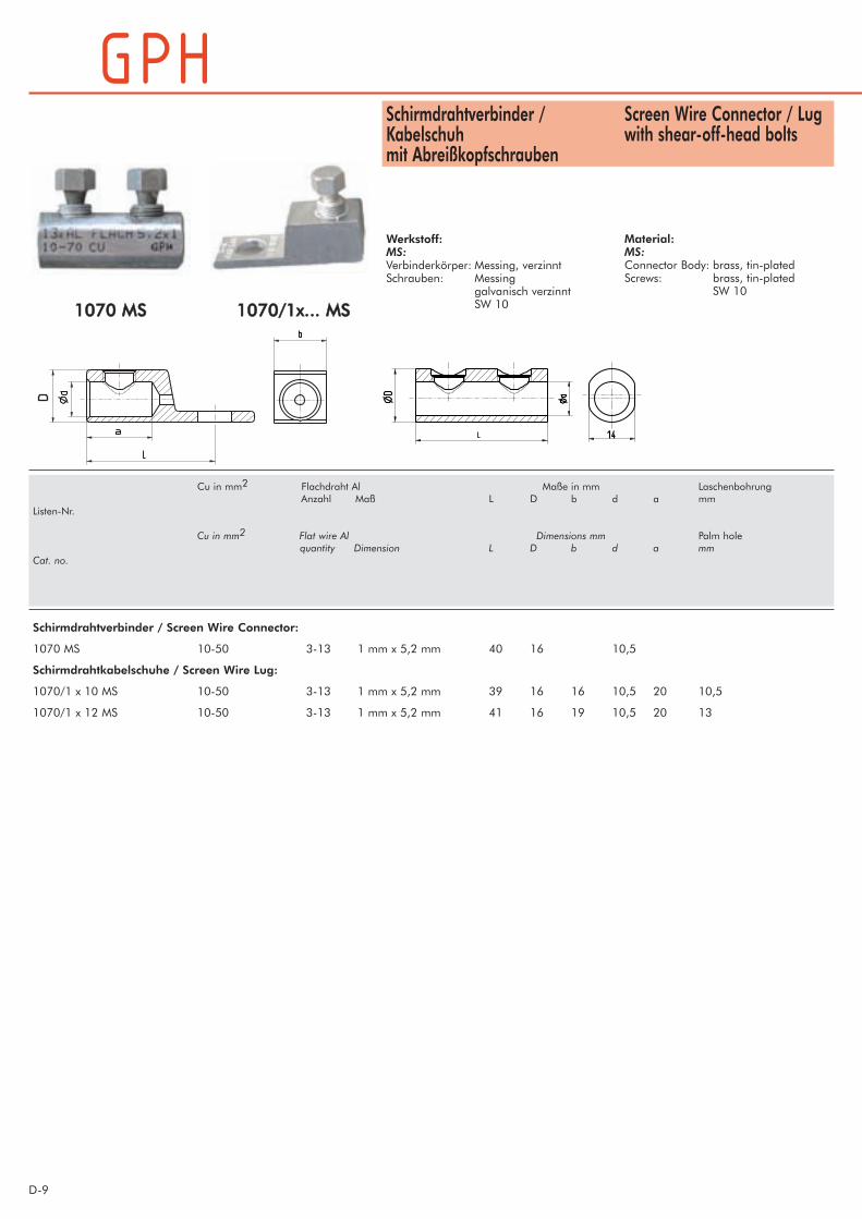
11007700 MMSS
Schirmdrahtverbinder / Screen Wire Connector:
1070 MS 10-50 3-13 1 mm x 5,2 mm 40 16 10,5
Schirmdrahtkabelschuhe / Screen Wire Lug:
1070/1 x 10 MS 10-50 3-13 1 mm x 5,2 mm 39 16 16 10,5 20 10,5
1070/1 x 12 MS 10-50 3-13 1 mm x 5,2 mm 41 16 19 10,5 20 13
Cu in mm2 Flachdraht Al Maße in mm LaschenbohrungAnzahl Maß L D b d a mm
Listen-Nr.
Cu in mm2 Flat wire Al Dimensions mm Palm holequantity Dimension L D b d a mm
Cat. no.
11007700//11xx...... MMSS
Screen Wire Connector / Lugwith shear-off-head bolts
Material:MS:Connector Body: brass, tin-platedScrews: brass, tin-plated
SW 10
Schirmdrahtverbinder /Kabelschuhmit Abreißkopfschrauben
Werkstoff:MS:Verbinderkörper: Messing, verzinntSchrauben: Messing
galvanisch verzinntSW 10

D- 10
Mechanical Cable Lugs, excentricwith 1 or 2 shear-off-head bolts
Material:Cable Lug Body: high strength
aluminium alloyBolts: brass,
tin-plated
Surface:Cable Lug Body: tin-plated
Schraubkabelschuhe, exzentrischmit 1 oder 2 Abreißkopfschrauben
Werkstoff:Kabelschuh-körper: Alu-LegierungSchrauben: Messing,
galvanisch verzinnt
Oberfläche:Kabelschuh-körper: galvanisch verzinnt
22559955 SSKK--VV--KK
1 625/1x12 SK-V-K 16-35 16-25 6-35 16-35 10-25 16-25 4-25 18 9 16 40 13 SW 10
2 2595/1x12 SK-V-K 25-95 25-95 25-95 25-95 25-95 25-95 10-35 32,5 14 28 60 13 SW 13
3 25185/2x12 SK-V-K 35-185 35-1851) 25-185 35-1851) 25-150 25-150 25-35 56 21 33 95 13 SW 19
4 120240/2x12 SK-V-K 120-240 120-2401)120-185 120-185 120-185 120-185 - 64 23 38 105 13 SW 22
1) rundgedrückt 1) round pressed
Alle aufgeführten Positionen für Anschluß an Bolzen M12;andere Laschenbohrungen auf Anfrage.
All items for bolt M12;other palm hole diameters on request.
Position Listen-Nr. Al in mm2 nach VDE 0295 Cu in mm2 nach VDE 0295 Maße in mm Laschen- SWrm sm re se rm sm re a d D L bohrung Sechskant
mm außen
Item Cat. no. Al in mm2 acc. to VDE 0295 Cu in mm2 acc. to VDE 0295 Dimesions mm Palm hole Width across flatround sector round sector round sector round a d D L mmstranded stranded solid solid stranded stranded solid
D-11
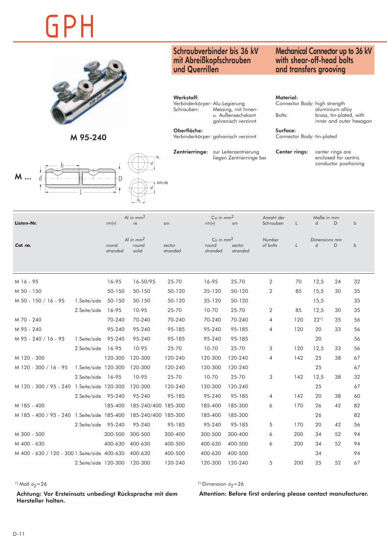
Mechanical Connector up to 36 kVwith shear-off-head bolts and transfers grooving
Material:Connector Body: high strength
aluminium alloyBolts: brass, tin-plated, with
inner and outer hexagon
Surface:Connector Body: tin-plated
Center rings: center rings are enclosed for centric conductor positioning
Schraubverbinder bis 36 kV mit Abreißkopfschraubenund Querrillen
Werkstoff:Verbinderkörper: Alu-LegierungSchrauben: Messing, mit Innen-
u. Außensechskantgalvanisch verzinnt
Oberfläche:Verbinderkörper: galvanisch verzinnt
Zentrierringe: zur Leiterzentrierung liegen Zentrierringe bei
MM 9955--224400
MM ......
M ...
M70-240
1) Maß d2=26 1) Dimension d2=26
Achtung: Vor Ersteinsatz unbedingt Rücksprache mit demHersteller halten.
Attention: Before first ordering please contact manufacturer.
Al in mm2 Cu in mm2 Anzahl der Maße in mmListen-Nr. rm(v) re sm rm(v) sm Schrauben L d D b
Al in mm2 Cu in mm2 Number Dimensions mmCat. no. round round sector round sector of bolts L d D b
stranded solid stranded stranded stranded
M 16 - 95 16-95 16-50/95 25-70 16-95 25-70 2 70 12,5 24 32
M 50 - 150 50-150 50-150 50-120 35-120 50-120 2 85 15,5 30 35
M 50 - 150 / 16 - 95 1.Seite/side 50-150 50-150 50-120 35-120 50-120 15,5 35
2.Seite/side 16-95 10-95 25-70 10-70 25-70 2 85 12,5 30 35
M 70 - 240 70-240 70-240 70-240 70-240 70-240 4 120 221) 35 56
M 95 - 240 95-240 95-240 95-185 95-240 95-185 4 120 20 33 56
M 95 - 240 / 16 - 95 1.Seite/side 95-240 95-240 95-185 95-240 95-185 20 56
2.Seite/side 16-95 10-95 25-70 10-70 25-70 3 120 12,5 33 56
M 120 - 300 120-300 120-300 120-240 120-300 120-240 4 142 25 38 67
M 120 - 300 / 16 - 95 1.Seite/side 120-300 120-300 120-240 120-300 120-240 25 67
2.Seite/side 16-95 10-95 25-70 10-70 25-70 3 142 12,5 38 32
M 120 - 300 / 95 - 240 1.Seite/side 120-300 120-300 120-240 120-300 120-240 25 67
2.Seite/side 95-240 95-240 95-185 95-240 95-185 4 142 20 38 60
M 185 - 400 185-400 185-240/400 185-300 185-400 185-300 6 170 26 42 82
M 185 - 400 / 95 - 240 1.Seite/side 185-400 185-240/400 185-300 185-400 185-300 26 82
2.Seite/side 95-240 95-240 95-185 95-240 95-185 5 170 20 42 56
M 300 - 500 300-500 300-500 300-400 300-500 300-400 6 200 34 52 94
M 400 - 630 400-630 400-630 400-500 400-630 400-500 6 200 34 52 94
M 400 - 630 / 120 - 300 1.Seite/side 400-630 400-630 400-500 400-630 400-500 34 94
2.Seite/side 120-300 120-300 120-240 120-300 120-240 5 200 25 52 67

D- 12
Mechanical Connector up to 36 kVwith shear-off-head boltsand longitudinal groovingMaterial:Connector Body: high strength
aluminium alloyBolts: brass, tin-plated
with inner and outer hexagon
Surface:Connector Body: tin-plated
Center rings: center rings are enclosed for centric conductor positioning
Schraubverbinder bis 36 kV mit Abreißkopfschraubenund LängsrillenWerkstoff:Verbinderkörper: Alu-LegierungSchrauben: Messing, galvanisch verzinnt
mit Innen- u. Außensechskant
Oberfläche:Verbinderkörper: galvanisch verzinnt
Zentrierringe: zur Leiterzentrierung liegen Zentrierringe bei MMRRLL // MMRRLLTT 9955--224400
MMRRLLTT MMRRLL
1) rundgedrückt 1) round pressed
Al in mm2 Cu in mm2 Anzahl der Maße in mmListen-Nr. rm(v) re sm rm(v) sm Schrauben L d D b
Al in mm2 Cu in mm2 Number Dimensions mmCat. no. round round sector round sector of bolts L d D b
stranded solid stranded stranded stranded
MRL 95 - 240 95-240 95-240 95-240 95-185 95-185 4 120 20 33 56
MRLT 95 - 240 95-240 95-240 95-2401) 95-185 95-185 4 120 20 33 56
MRLT 95 - 240 / 16 - 95 1.Seite/side 95-240 95-240 95-2401) 95-185 95-185 3 120 20 33 56
2.Seide/side 16-95 10-95 25-70 10-70 25-70 12,5 40
Achtung: Vor Ersteinsatz unbedingt Rücksprache mit demHersteller halten.
Attention: Before first ordering please contact manufacturer.

D-13
Split-Bolt Mechanical Connectorup to 36 kVwith shear-off-head bolts
Material:Connector Body: high strength
aluminium alloyBolts: brass, tin-plated, with
inner and outer hexagonSB70-240:high strength aluminiumalloy, non tin-plated
Surface:Connector Body: tin-plated, separable
Center rings: center rings are enclosed for centric conductor positioning
Split-Bolt Schraubverbinderbis 36 kV mit Abreißkopfschrauben
Werkstoff:Verbinderkörper: Alu-LegierungSchrauben: Messing, mit Innen-
u. Außensechskant,galvanisch verzinntSB70-240:Alu-Legierung, blank
Oberfläche:Verbinderkörper: galvanisch verzinnt,
teilbar
Zentrierringe: zur Leiterzentrierung liegen Zentrierringe bei
SB120-300SB185-400
SB70-240
SB70-240
SB70-240 70-240 70-240 70-240 70-240 70-240 4 144 22 35 56 26
SB120-300 120-300 120-300 120-240 120-300 120-240 4 170 25 38 67 -
SB185-400 185-400 185-240/400 185-300 185-400 185-300 6 200 26 42 82 -
Achtung: Vor Ersteinsatz unbedingt Rücksprache mit demHersteller halten.
Attention: Before first ordering please contact manufacturer.
Al in mm2 Cu in mm2 Anzahl der Maße in mmListen-Nr. rm(v) re sm rm(v) sm Schrauben L d1 D b d2
Al in mm2 Cu in mm2 Number Dimensions mmCat. no. round round sector round sector of bolts L d1 D b d2
stranded solid stranded stranded stranded

D- 14
Mechanical Cable Lugs, centricwith 1, 2 or 3 shear-off-headbolts
Material:Connector Body: high strength
aluminium alloyBolts: brass, tin-plated,
with inner and outerhexagon
Surface:Connector Body: tin-plated
Center rings: center rings are enclosed for centric conductor positioning
Schraubkabelschuhe, zentrischmit 1, 2 oder 3Abreißkopfschrauben
Werkstoff:Verbinderkörper: Alu-LegierungSchrauben: Messing,
galvanisch verzinnt,mit Innen-u. Außensechskant
Oberfläche:Verbinderkörper: galvanisch verzinnt
Zentrierringe: zur Leiterzentrierung liegen Zentrierringe bei
CC 9955--224400
C ...
C70-240
1) Maß d2=26 1) Dimension d2=26
C 16 - 95 x 12 16-95 16-50/95 25-70 16-95 25-70 1 60 12,5 24 32 13C 16 - 95 x 16
C 50 - 150 x 12 50-150 50-150 50-120 35-120 50-120 1 79 15,5 30 35 13C 50 - 150 x 16 17
C 70 - 240 x 12 70-240 70-240 70-240 70-240 70-240 2 93,5 221) 35 56 13C 70 - 240 x 16 17
C 95 - 240 x 12 95-240 95-240 95-185 95-240 95-185 2 95 20 33 56 13C 95 - 240 x 16 17
C 120 - 300 x 12 120-300 120-300 120-240 120-300 120-240 2 105 25 38 67 13C 120 - 300 x 16 17
C 185 - 400 x 12 185-400 185-240/400 185-300 185-400 185-300 3 120 26 42 82 13C 185 - 400 x 16 17
C 400 - 630 x 12 13C 400 - 630 x 16 400-630 400-630 400-500 400-630 400-500 3 130 34 52 94 17C 400 - 630 x 20 21
Andere Laschenbohrungen auf Anfrage. Further palm holes on demand.
Al in mm2 Cu in mm2 Anzahl der Maße in mm LaschenbohrungListen-Nr. rm(v) re sm rm(v) sm Schrauben L d D a mm
Al in mm2 Cu in mm2 Number Dimensions mm Palm holeCat. no. round round sector round sector of bolts L d D a mm
stranded solid stranded stranded stranded
D-15
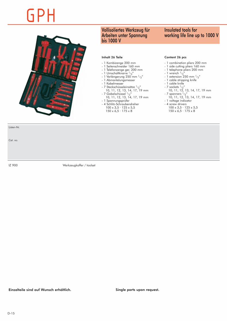
Insulated tools forworking life line up to 1000 V
Content 26 pcs
- 1 combination pliers 200 mm- 1 side cutting pliers 160 mm- 1 telephone pliers 200 mm- 1 wrench 1/2”- 1 extension 250 mm 1/2”- 1 cable stripping knife- 1 cable knife- 7 sockets 1/2”10, 11, 12, 13, 14, 17, 19 mm
- 7 spanners 1/2”10, 11, 12, 13, 14, 17, 19 mm
- 1 voltage indicator- 4 screw drivers100 x 3,5 · 125 x 5,5150 x 6,5 · 175 x 8
Vollisoliertes Werkzeug fürArbeiten unter Spannungbis 1000 V
Inhalt 26 Teile
- 1 Kombizange 200 mm- 1 Seitenschneider 160 mm- 1 Telefonzange ger. 200 mm- 1 Umschaltknarre 1/2”- 1 Verlängerung 250 mm 1/2”- 1 Abmantelungsmesser- 1 Kabelmesser- 7 Steckschüsseleinsätze 1/2”10, 11, 12, 13, 14, 17, 19 mm
- 7 Gabelschüssel 1/2”10, 11, 12, 13, 14, 17, 19 mm
- 1 Spannungsprüfer- 4 Schlitz-Schraubendreher100 x 3,5 · 125 x 5,5150 x 6,5 · 175 x 8
IZ 900 Werkzeugkoffer / toolset
Einzelteile sind auf Wunsch erhältlich.
Listen-Nr.
Cat. no.
Single parts upon request.
D- 16
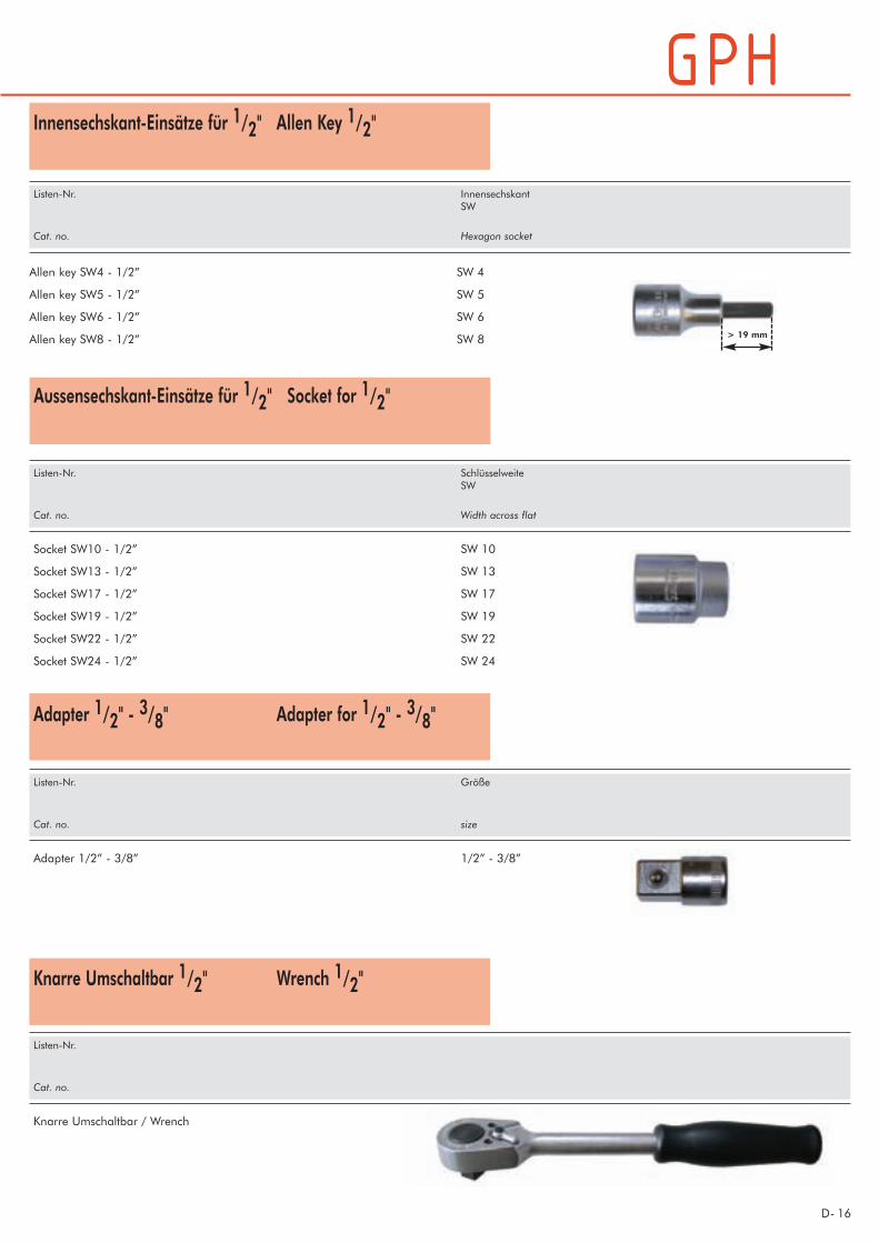
Innensechskant-Einsätze für 1/2" Allen Key 1/2"
Aussensechskant-Einsätze für 1/2" Socket for 1/2"
Adapter 1/2" - 3/8" Adapter for 1/2" -
3/8"
Knarre Umschaltbar 1/2" Wrench 1/2"
Listen-Nr. InnensechskantSW
Cat. no. Hexagon socket
Allen key SW4 - 1/2” SW 4
Allen key SW5 - 1/2” SW 5
Allen key SW6 - 1/2” SW 6
Allen key SW8 - 1/2” SW 8 > 19 mm
Listen-Nr. SchlüsselweiteSW
Cat. no. Width across flat
Socket SW10 - 1/2” SW 10
Socket SW13 - 1/2” SW 13
Socket SW17 - 1/2” SW 17
Socket SW19 - 1/2” SW 19
Socket SW22 - 1/2” SW 22
Socket SW24 - 1/2” SW 24
Listen-Nr. Größe
Cat. no. size
Adapter 1/2” - 3/8” 1/2” - 3/8”
Listen-Nr.
Cat. no.
Knarre Umschaltbar / Wrench
D-17
Special Grease GPH 10
protects conductor and fitting in mecha-nical connections from corrosion ensu-ring a good electrical contact.
Spezialfett GPH 10
schützt Leiter und Armatur in Schraub-verbindungen dauerhaft gegenKorrosion und garantiert damit einegute elektrische Verbindung.
GPH 10 6201 01 08 1000 g
Listen-Nr. EDV-Nr. Gewicht/Dose
Cat. no. EDV no. Weight/can

D- 18
Holding Tool
To avoid twisting while tightening thescrews we recommend the usage of theholding tool.
Can work on live parts with voltages upto 1000V AC and 1500V DC.
Gegenhalter
Zur Verdrehsicherung des Verbindersbei der Montage empfehlen wir denEinsatz eines Gegenhalters.
Geeignet zum Arbeiten unter Spannungbis 1000V AC und 1500V DC.
GGHH 4400 II--VV
GH 40 I-V isoliert, Verbinderdurchmesser 14-40 mm insulated, connector diameter 14-40 mm
Listen-Nr. Einsatzbereich Usage for
Cat. no.
D-19
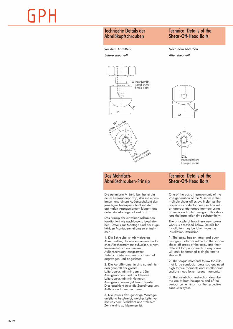
Technical Details of theShear-Off-Head Bolts
Nach dem Abreißen
After shear-off
Technische Details derAbreißkopfschrauben
Vor dem Abreißen
Before shear-off
M
Sollbruchstellerated shearbreak point
R
Technical Details of theShear-Off-Head Bolts
One of the basic improvements of the2nd generation of the M-series is themultiple shear off screw. It clamps therespective conductor cross section withan appropriate torque moment usingan inner and outer hexagon. This shor-tens the installation time substantially.
The principle of how these new screwsworks is described below. Details forinstallation may be taken from theinstallation instruction.
1. The screw has an inner and outerhexagon. Both are related to the variousshear-off-areas of the screw and theirdifferent torque moments. Every screwwill only be fastened a single time toshear-off.
2. The torque moments follow the rulethat large conductor cross sections needhigh torque moments and smaller crosssections need lower torque moments.
3. The installation instruction describethe use of both hexagons and of thevarious center rings, for the respectiveconductor types.
Das Mehrfach-Abreißschrauben-Prinzip
Die optimierte M-Serie beinhaltet einneues Schraubenprinzip, das mit einemInnen- und einem Außensechskant denjeweiligen Leiterquerschnitt mit demoptimalen Anzugsmoment klemmt unddabei die Montagezeit verkürzt.
Das Prinzip der einzelnen Schraubenfunktioniert wie nachfolgend beschrie-ben, Details zur Montage sind der zuge-hörigen Montageanleitung zu entneh-men:
1. Die Schraube ist mit mehrerenAbreißstellen, die alle ein unterschiedli-ches Abschermoment aufweisen, einemInnensechskant und einemAußensechskant ausgestattet.Jede Schraube wird nur noch einmalangezogen und abgerissen.
2. Die Abreißmomente sind so definiert,daß generell der größteLeiterquerschnitt mit dem größtenAnzugsmoment und der kleinereLeiterquerschnitt mit kleinerenAnzugsmomenten geklemmt werden.Dies geschieht über die Zuordnung vonAußen- und Innensechskant.
3. Die jeweils dazugehörige Montage-anleitung beschreibt, welcher Leitertypmit welchem Sechskant und welchemZentrierring zu klemmen ist.

Der Nachdruck dieses Katalogs ist, auch auszugsweise, nur mit besonde-rer Erlaubnis gestattet.
Die angegebenen Daten wurden gewissenhaft ermittelt, sie geben jedochnur Richtwerte an und befreien Sie nicht von der eigenen Prüfung der vonuns gelieferten Produkte auf ihre Eignung für die beabsichtigten Zwecke.Verarbeitung und Anwendung der Produkte erfolgen außerhalb unsererKontrollmöglichkeit und liegen daher ausschließlich in Ihrem Verantwor-tungsbereich.
Die Abbildungen und Zeichnungen sind nicht unbedingt maßgebend. DieGewichtsangaben sind annähernd und schließen die Kartonverpackungmit ein. Nach Möglichkeit sind nur komplette Normalverpackungen zubestellen.
Das Verbindungsmaterial wird vorwiegend in Kartons verpackt geliefert.Wir verwenden nur recyclingfähige Verpackungsmaterialien nach derneuen Verpackungsordnung. Faltkartons werden nicht zurückgenommen.
Änderungen bleiben uns ausdrücklich vorbehalten. Mit diesem Katalogwerden frühere Ausgaben ungültig.
Unsere Erzeugnisse entsprechen den einschlägigen VDE-Bestimmungen,bzw. - soweit erschienen - den entsprechenden DIN-Blättern und IEC-Empfehlungen.
Unsere Geschäftsbedingungen entsprechen der jeweils neuesten Ausgabeder "Allgemeinen Lieferbedingungen für Erzeugnisse und Leistungen derElektroindustrie". Auf Wunsch senden wir Ihnen eine Kopie zu.
Ausführungen, die nicht im Katalog enthalten sind, erhalten Sie auf An-frage.
Hof, im Februar 2010
Reprinting, even partial, only with special allowance.
The data given were determined diligently, they are however only guidevalues and do not release our customers of the duty to carry out teststhemselves in order to check the suitability of the products delivered by usfor the intended use.Processing and use of the products cannot be controlled by us and aretherefore exclusively in your field of responsibility.
Illustrations and drawings may only show a close reflection and are notdecisive. The weights are approximate and include the carton package.Our products are mainly delivered in cartons. Please try to order completestandard packages.
We only use package materials able to be recycled due to the latest pak-king system.Collapsible cardboard boxes are not taken back.
We reserve the right to alter or modify the characteristics described.This catalogue substitutes all former editions.
Our products meet the VDE standards respectively correspond to DINpages and IEC recommendations.
Our responsibilities are only those listed in the latest edition of “GeneralTerms and Conditions for the Supply of Products and Services of the Elec-trical and Electronics Industry”. If requested we provide a copy.
Types or versions not part of the catalogue you receive on request.
Hof, February 2010

SchraubverbinderSchraubkabelschuhe
Katalog D
Mechanical ConnectorsMechanical Cable Lugs
Catalog D
Nexans Power Accessories Germany GmbHFerdinand-Porsche-Str. 12 95028 Hof/Saale Telefon +49 (0)9281 83060Postfach 1406 95013 Hof/Saale Telefax +49 (0)9281 830630http://www.nexans-power-accessories.com e-mail: [email protected]
Endbundklemmen
Mehrzweckklemmen
Endabspannklemmen
Abzweigklemmen
Schlitzklemmen
ISO-Abzweigklemmen
Kerbverbinder
Pressverbinder
Reduzierhülsen
Schraubverbinder
Schraubkabelschuhe
Direktanschlussklemmen
Presskabelschuhe
Cupalscheiben
Klemmkabelschuhe
Endverschlussbolzen
Pressanschlüsse
Werkzeuge
Kontakt Fett
Dead-End Clamps
Universal Overhead Line Clamps
Dead-End Clamps Cone-type
Parallel Grove Clamps
Split Bolt Connectors
ISO-Tap-off clamps
Notch Type Midspan Joints
Compression Joints
Reduction Sleeves
Mechanical Connectors
Mechanical Cable Lugs
Terminal Clamps
Compression Cable Lugs
Cupaldisks
Cable Lugs Clamping-type
End-Compression Terminal Pin-type
Compression Terminal Pin-type
Tools
Contact Grease
Nexans Power Accessories Germany GmbHFerdinand-Porsche-Str. 12 95028 Hof/Saale Telefon +49 (0)9281 83060Postfach 1406 95013 Hof/Saale Telefax +49 (0)9281 830630http://www.nexans-power-accessories.com e-mail: [email protected]
Pamela Kinnell
Address Stamp