News from Rohde & Schwarz...4 News from Rohde & Schwarz Number 150 (1996/I) Number 150 1996/I Volume...
64
News from Rohde & Schwarz New test technology for module production Digital monitoring direction finders for HF to UHF ecoTV: solid-state transmitters set the pace in terms of economy 150
Transcript of News from Rohde & Schwarz...4 News from Rohde & Schwarz Number 150 (1996/I) Number 150 1996/I Volume...

News from Rohde & Schwarz
New test technologyfor module production
Digital monitoring direction findersfor HF to UHF
ecoTV: solid-state transmitters set the pace in terms of economy
150
“60 years Rohde & Schwarz – 60 years of a life dedicated to Rohde& Schwarz” – this is the heading Dr. Hermann Schwarz chose for an article in “Zeitzeichen”, the inhousemagazine for Rohde & Schwarzemployees, on the occasion of thecompany’s 60th anniversary. Now,only two years later, this life has ended. Dr. Dr. E. h. Hermann Schwarzpassed away in his 88th year on theevening of 10 November 1995.
Born in the old free city of Nördlingenin Swabia in 1908, he was to livethrough all ten decades of the 20thcentury, turbulent and history-laden asthey were. His youth in his hometownand the holidays he spent on the farmsof relatives in the nearby country werethe basis for his life-long and deeplyfelt love of nature, which probably
contributed to his decision to study natural sciences following grammarschool in Nuremberg. He began hisstudies of physics, mathematics andgeophysics in Heidelberg, continuedin Munich - the time he spent here wascertainly one factor in his decision toset up business in this city a few yearslater – and finished in Jena, where heattended lectures by Prof. Esau andMax Wien, met his future friend andpartner Lothar Rohde and received hisdoctorate in 1931. Finding a job wasvery difficult for young physicists in a time of economic depression, so the two friends stayed on at universityfor two more years. The contacts to industry they made there, however,encouraged them to set up their ownenterprise in Munich in 1933. With the Physico-technical Development Laboratory Dr. Rohde & Dr. Schwarz
they laid the foundation for the compa-ny Rohde & Schwarz, an internationalenterprise, which today employs morethan 4,000 people and is still inde-pendent.
While R&D in the laboratory – with afocus on impedance and dissipation-factor measurements – still made upthe bulk of Hermann Schwarz’s workin the first few years, he was also fromthe beginning responsible for organ-izational and administrative tasks. Asboth the staff and premises of the en-terprise expanded, he had to dedicatemore and more of his time to com-pany policy with regard to personneland management, which on the otherhand encouraged his solid talents for business. It had been his idea, forinstance, that designs developed byRohde & Schwarz should not be sold
It is with deep sorrow that we say a last farewell to the highlyesteemed senior partner and co-founder of our company
who passed away on 10 November 1995 at the age of 87.
Dr. Hermann Schwarz, a pioneer of test and communication engineering
Executive Board, Company Management,Employees and Workers’ Council of
ROHDE & SCHWARZ GmbH & Co. KG
Dr. phil. nat. Dr. E. h. Hermann Schwarz
but produced by the company itself.Acquisition of the premises at Tassilo-platz in Munich in 1937 again showedhis grasp of future perspectives. Asthe price for the new premises was almost twice the small company’s balance-sheet total of the previousyear, this venturesome step was a trueentrepreneurial decision which can beseen as the next milestone followingthe start of the company. The companywas now ready for further growth,and at the outbreak of World War II already had 100 employees. Formany major firms in the communica-tions sector R&S was the regular sup-plier of the test equipment they neededfor production. As a consequence,R&S soon ran out of space, so the Tassiloplatz building had to be ex-tended and new buildings added. Inthose years Hermann Schwarz wasconfronted with difficult decisions suchas the city council’s plans to relocatethe company or the need to find newproduction sites after air raids hadcaused damage. These questions wereof significance for the very existenceof the company and its employees,who by then numbered several hundreds. The partnership of the two owners was also put to many a test butproved to withstand all difficulties.
At that time, true entrepreneurial visionwas required to maintain one’s powerof judgement despite all political andeconomic problems. The same is trueof the time of post-war reconstructionthat followed, although it provided amuch more gratifying basis. The posi-tive economic trend was reflected inthe purposeful yet careful expansionof the new plant on Mühldorfstrasse in Munich. It was at this stage that Hermann Schwarz could explicitly putto use his entrepreneurial flair. The decisions to set up MessgerätebauGmbH in Memmingen, the R&S plantin Cologne, sales offices in various locations and later the productionplant in Teisnach in the Bavarian For-est are further milestones that give evidence of Hermann Schwarz’s in-itiative. Another important area was
expansion of the group on both thedomestic and international market, inparticular by building up a large salesnetwork in Europe, Asia and America.This gave him a chance to get to knowother countries and peoples and to acquire friends around the world. Justlike his employees, they admired himfor his charm, honesty and sense of social responsibility, but also for hisability to formulate cogent arguments,for his extraordinary knowledge of history and almost endless supply ofquotations.
Hermann Schwarz showed again that he was very much aware of his responsibility for the future of the com-pany by making provisions for suc-cession in 1971 in order to be able to cope with any possible course of affairs or risks. After his son Friedrichhad completed his education and train-ing with excellent results, HermannSchwarz appointed him to the Ex-ecutive Board, allowing himself to re-duce his personal involvement in man-agement tasks and hand over respon-sibility step by step. When he finallygave up Human Resources – his lastfield of work – he left behind an areaof management that had particularlybenefited from the extraordinary hu-manness of his character for decades.The fact that he always demandedvery high standards of his own workwith people made him fit as a rolemodel. This was something his em-ployees could always feel; he inspiredtheir confidence by having confidencein them. Throughout his life he com-bined entrepreneurial leadership withhumanist values and thus acquired afather-like aura for many in the com-pany. Employees and friends alwaystreasured his fairness, his deep knowl-edge of human nature, his love of life,his tolerance, his charm, which wasvisible through an often patriarchalsurface, and his exemplary esteem forfamily ties. These qualities enabledhim to make friends not only in his im-mediate surroundings but also amongpeople he met pursuing his hobbies,namely hunting and fishing, which
had evolved from his early love of nature and which he cultivated enthu-siastically thus finding recreation fromthe stress of everyday work.
Understandably, his invaluable con-tribution to society was officially recognized. As early as 1959 theTechnical University of Munich ap-pointed Dr. Schwarz honorary sena-tor. He was also a commercial judgefor many years, and in 1971 becamehonorary consul of the Republic of Iceland. Besides other decorations hewas awarded the Bavarian Order ofMerit, the Commander’s Cross of theOrder of Merit of the Federal Republicof Germany, the Medal for Contribu-tions to the Bavarian Economy and theGolden Medal of Honour of the City ofMunich. For his exemplary industrialpolicy he received the Seal of the Cityof Memmingen in 1984 and becamehonorary citizen of Teisnach. It wasparticularly gratifying for HermannSchwarz to become honorary doctorof his former university in Jena in 1991after German reunification.
Albert Habermann
4 News from Rohde & Schwarz Number 150 (1996/I )
Number 150 1996/I Volume 36
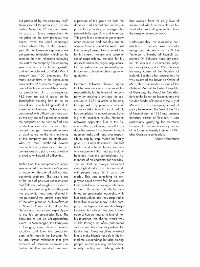
In RF measurements, network analysis is the most important task beside spectral analysis andtest signal generation. Rohde & Schwarz haslaunched a complete family of top-grade vectornetwork analyzers, namely entry-level modelZVRL, standard model ZVRE and general-purposemodel ZVR – in short, the perfect solution for any requirement and any budget (see article onpage 6).
Dr. Olaf Ostwald; Vector Network Analyzer Family ZVRChristian Evers To the heart of the chart . . . . . . . . . . . . . . . . . . . . . . . . . . . . . . . . . . . . . . . . . . . . . . . . . . . . . . .6
Dr. Lothar Tschimpke LaserVision System LV1Optical insertion testing combined with classic board test . . . . . . . . . . . . . . . . . . . . .10
Klaus Kundinger; Universal Test System TSUDr. Lothar Tschimpke Versatile test platform for production and service of electronic modules. . . . . . . . .13
Michael Lehmann; TV Monitoring and Test Systems TS6100Gerhard Strauss Video and audio parameters of TV transmitters all under control . . . . . . . . . . . . . . .16
Josef Wolf Spectrum Analyzer FSE with Option FSE-B7Vector signal analysis – indispensable in digital mobile radio. . . . . . . . . . . . . . . . . .19
Franz Demmel; Ulrich Unselt; Digital Monitoring Direction Finders DDF0xMDr. Eckhard Schmengler State-of-the-art monitoring direction finding from HF to UHF . . . . . . . . . . . . . . . . . . .22
Hans Seeberger Solid-state UHF TV Transmitter NH500The new reference for TV transmitters: ecoTV. . . . . . . . . . . . . . . . . . . . . . . . . . . . . . . . . .26
Franz Demmel; 150-W HF Dipole HX002A1Axel Klein The antenna for reliable shortwave links . . . . . . . . . . . . . . . . . . . . . . . . . . . . . . . . . . . . . .29
Albert Winter Test signals for digital television . . . . . . . . . . . . . . . . . . . . . . . . . . . . . . . . . . . . . . . . . . . . . .32
Michael Manert; Wilfried Tiwald BER measurements with Base-Station Test System TS8510 . . . . . . . . . . . . . . . . . . . . .34
Martin Schlechter Loudspeaker measurements with Audio Analyzer UPD. . . . . . . . . . . . . . . . . . . . . . . . .36
Mathias Leutiger; Daniel Schröder Signal Generator SME for tests on ERMES, FLEX and POCSAG pagers . . . . . . . .38
Otmar Wanierke Interference analysis in digital mobile-radio networks. . . . . . . . . . . . . . . . . . . . . . . . . .40
Martin Flach Longterm monitoring of digital serial video signal using Digital Video Component Analyzer VCA . . . . . . . . . . . . . . . . . . .42
Richard Finkenzeller; Ernst Polz Measuring all TV RF and video parameters for the first time in a compact unit . .44
Manfred Jungherz; Radiocommunication system helps ItalianPeter Maurer customs authorities in coastal monitoring. . . . . . . . . . . . . . . . . . . . . . . . . . . . . . . . . . . . . .46
Articles
Peter Hatzold Digital modulation and mobile radio (I) . . . . . . . . . . . . . . . . . . . . . . . . . . . . . . . . . . . . . .48
Application notes
Refresher topic
5News from Rohde & Schwarz Number 150 (1996/I )
Published by ROHDE & SCHWARZ GmbH & Co. KG Mühldorfstraße 15 D -81671 MunichTelephone (0 89) 41 29-0 · international *(4989) 41 29-0 · Telex 523703 (rs d) · Editors: H. Wegener and G. Sönnichsen (German); C. B. Newberry, I. Davidson, G. Koranyi (English) · Photos: S. Huber ·Circulation 100 000 three times a year · ISSN 0028-9108 · Supply free of charge · State company orposition · Printed in the Federal Republic of Germany by peschke druck, Munich · Reproduction of extracts permitted if source is stated and copy sent to R & S Munich
Imprint
Panorama
Hans Wagner Remarks on the future of radiocommunications . . . . . . . . . . . . . . . . . . . . . . . . . . . . . . . .52
Michael Vohrer Multimode Radiocommunication Tester CMDfor GSM, PCN, PCS and DECT mobiles . . . . . . . . . . . . . . . . . . . . . . . . . . . . . . . . . . . . . .53
Michael Vohrer Low-cost Service Radiocommunication Testers CMD50/53for GSM/PCN/PCS mobiles . . . . . . . . . . . . . . . . . . . . . . . . . . . . . . . . . . . . . . . . . . . . . . . . .54
Thomas Maucksch CMD compact tester R4860 tests telephones of Japanese mobile radio network PDC. . . . . . . . . . . . . . . . . . . . . . . . . . . . . . . . . . . . . . .56
Dr. Andreas Waßerburger Gas chromatography for monitoringproduction processes in chemical industry . . . . . . . . . . . . . . . . . . . . . . . . . . . . . . . . . . . .57
Regular features
Wilhelm Kraemer Test hint: Installing directional antennas for microwave WLANs . . . . . . . . . . . . . . . .15
Reference: Matsushita relays in Audio Analyzer UPD measure the best of audio. . . . . . . . . . . . . . . . . . . . . . . . . . . . . . . . . . . . . . . . . . . . . . . . . . . .25
Albert Winter Software: Software SME-K1 for programmingthe data generator of Signal Generator SME . . . . . . . . . . . . . . . . . . . . . . . . . . . . . . . . .50
Prof. Dr.-Ing. Burkhard Schiek; Patent: Holger Heuermann Calibration method for network analyzers . . . . . . . . . . . . . . . . . . . . . . . . . . . . . . . . . . . .51
Newsgrams . . . . . . . . . . . . . . . . . . . . . . . . . . . . . . . . . . . . . . . . . . . . . . . . . . . . . . . . . . . . . . . . .58
Information in print/Booktalk: Der deutsche Rundfunk. . . . . . . . . . . . . . . . . . . . . . . . .60
Press comments . . . . . . . . . . . . . . . . . . . . . . . . . . . . . . . . . . . . . . . . . . . . . . . . . . . . . . . . . . . . . .61
Werner Baumgärtel Final article: Rohde & Schwarz system support – there’s system to our service. . .62
For module testing in production Rohde &Schwarz relies on combining various test methodsin a single unit. The wide spectrum of problemsfrom insertion errors through to non-compliancewith specifications is now mastered by one testsystem that applies the most appropriate testmethod for each situation. What has so far beenimpossible to detect by affordable electricalmeasurements can now easily be revealed by op-tical means such as laser and image processing.The customer’s benefits are high error-detectionrate, short test setup time and large throughput (see articles on pages 10 and 13).
6 News from Rohde & Schwarz Number 150 (1996/I )
The ZVR family comprises the threemodels ZVRL, ZVRE and ZVR, each tail-ored to a different field of application (FIG 1). The common features of allmodels are their ease of operation,lightning measurement speed and largefrequency range that covers 10 Hz,
9 kHz or 300 kHz to 4 GHz dependingon the integral test set selected (FIG 2).All models feature an IBM-PC compat-ible processor core with floppy-diskdrive, hard disk, slots for options aswell as external interfaces to connect akeyboard, mouse and up to two addi-tional monitors for the analyzer displayand the PC screen. This ensures easyanalysis of measurement results, theirprofessional documentation and effec-tive networking within the analyzer or with other systems. The effectiveness
tion environments and only requiressimple calibration methods such asnormalization and full oneport calibra-tion. Bidirectional Network AnalyzerZVRE is ideal for general-purpose appli-cations, as for instance in research anddevelopment labs where forward andreverse s-parameters of twoport deviceshave to be measured. Unlike ZVRL, ithas a test set with two bridges and anelectronic switch for quasi-simultaneousmeasurement of all four s-parameters.This paves the way for the increase in
Articles
of all models is further enhanced by accessories and options such as calibration and verification kits, three-port adapters or special firmware packages for frequency-converting andnonlinear measurements.
The entry-level model, unidirectionalVector Network Analyzer ZVRL, is forforward transmission and reflectionmeasurements which also provide derived quantities such as input imped-ance, VSWR or group delay. ZVRL isespecially designed for use in produc-
Vector Network Analyzer Family ZVR
To the heartof the chartVector Network Analyzer Family ZVR with its exceptionally high measurementspeed gives an entirely new view of aspects of RF circuits which cannot be revealed by conventional analyzers. It has a wide dynamic range thanks to fundamental mixing. An extremely large frequency range is covered by the inte-grated bridges. Innovative calibration methods such as TOM-X, TNA and AutoCalensure high measurement accuracy.
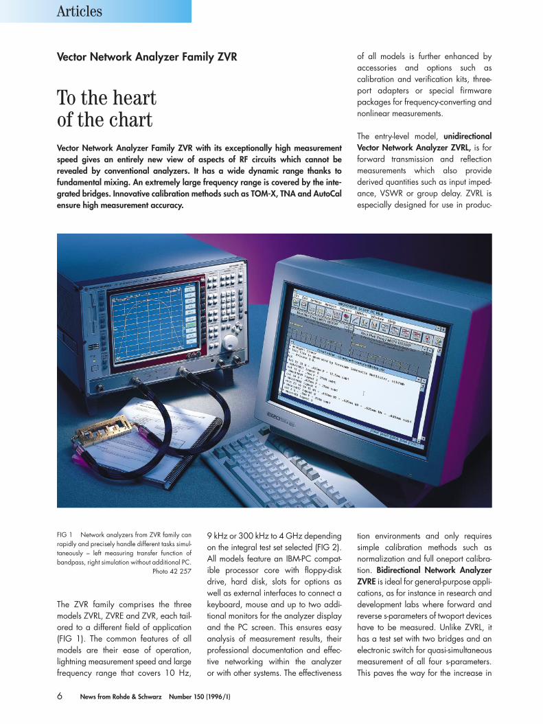
FIG 1 Network analyzers from ZVR family canrapidly and precisely handle different tasks simul-taneously – left measuring transfer function ofbandpass, right simulation without additional PC.
Photo 42 257
7News from Rohde & Schwarz Number 150 (1996/I )
measurement accuracy that can be obtained with full twoport system-errorcalibration [1].
Bidirectional four-channel NetworkAnalyzer ZVR allows the most sophis-ticated, novel calibration methods to be carried out. Unlike the three-channelZVRE, it has a second reference chan-nel after the electronic switch so that it is able to carry out a variety of in-novative calibration procedures (TOM,TRM, TRL, TNA, TOM-X) [2; 3]. Theseare characterized by increased con-venience and measurement accuracy,mathematically exact elimination ofsystem crosstalk (see Patent on page 51)and are also especially well-suited for in-fixture calibration. The new auto-matic calibration method AutoCal [4],for which a patent is pending, offersmaximum ease of operation and cali-bration speed. Full twoport calibrationof the analyzer takes less than 20 s withjust one through connection and with-out any further manual handling.
The core of all network analyzers of theZVR family is a fast synthesizer whichprovides crystal-accurate frequencychanges in less than 20 µs. Its amplifiedoutput signal is taken to the DUT via theintegral, model-specific configurabletest set of the analyzer. Its transmissionand reflection characteristics are meas-ured by means of a two-stage hetero-dyne receiver which uses fundamentalmixing and are digitally evaluated. Theanalyzers are equipped with a networkof eight microprocessors specially de-signed to perform the various internaltasks such as unit control, recording ofresults, data processing, screen graphicsand remote control of the unit. Meas-
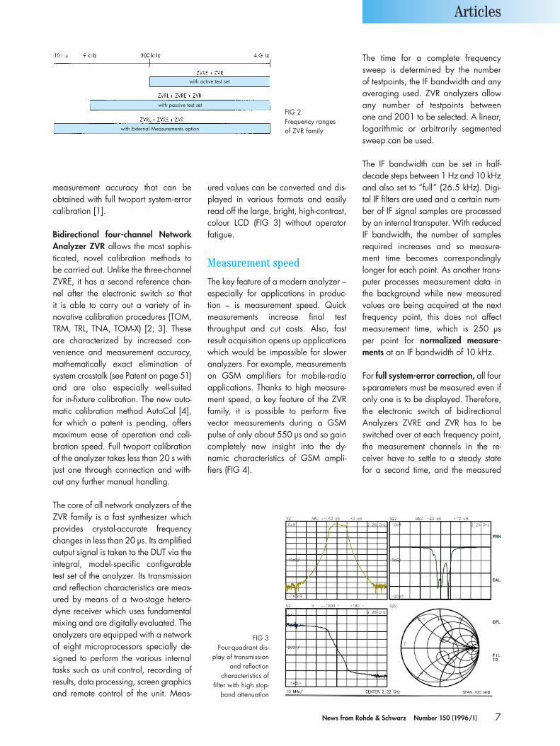
ured values can be converted and dis-played in various formats and easilyread off the large, bright, high-contrast,colour LCD (FIG 3) without operator fatigue.
Measurement speed
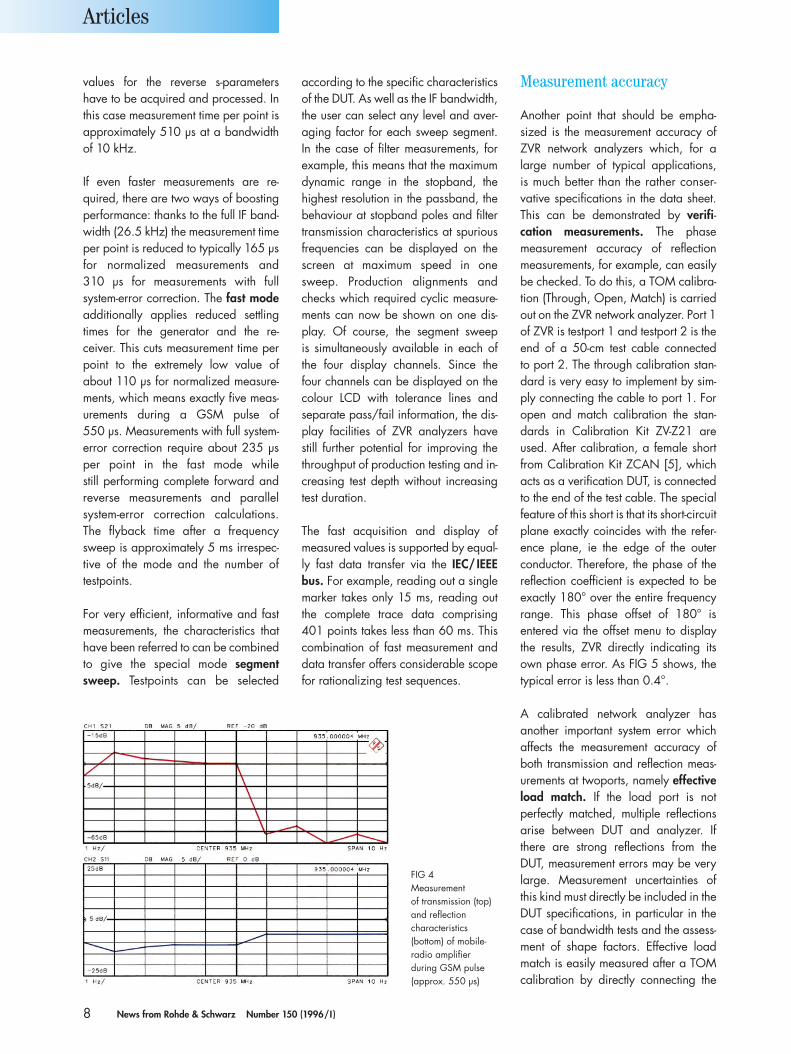
The key feature of a modern analyzer –especially for applications in produc-tion – is measurement speed. Quickmeasurements increase final testthroughput and cut costs. Also, fast result acquisition opens up applicationswhich would be impossible for sloweranalyzers. For example, measurementson GSM amplifiers for mobile-radio applications. Thanks to high measure-ment speed, a key feature of the ZVRfamily, it is possible to perform five vector measurements during a GSMpulse of only about 550 µs and so gaincompletely new insight into the dy-namic characteristics of GSM ampli-fiers (FIG 4).
The time for a complete frequencysweep is determined by the number of testpoints, the IF bandwidth and anyaveraging used. ZVR analyzers allowany number of testpoints between one and 2001 to be selected. A linear,logarithmic or arbitrarily segmentedsweep can be used.
The IF bandwidth can be set in half-decade steps between 1 Hz and 10 kHzand also set to “full” (26.5 kHz). Digi-tal IF filters are used and a certain num-ber of IF signal samples are processedby an internal transputer. With reducedIF bandwidth, the number of samplesrequired increases and so measure-ment time becomes correspondinglylonger for each point. As another trans-puter processes measurement data inthe background while new measuredvalues are being acquired at the nextfrequency point, this does not affectmeasurement time, which is 250 µs per point for normalized measure-ments at an IF bandwidth of 10 kHz.
For full system-error correction, all fours-parameters must be measured even ifonly one is to be displayed. Therefore,the electronic switch of bidirectionalAnalyzers ZVRE and ZVR has to beswitched over at each frequency point,the measurement channels in the re-ceiver have to settle to a steady state for a second time, and the measured
Articles
FIG 2Frequency ranges of ZVR family
FIG 3Four-quadrant dis-
play of transmissionand reflection
characteristics of filter with high stop-
band attenuation
with active test set
with passive test set
with External Measurements option
8 News from Rohde & Schwarz Number 150 (1996/I )
values for the reverse s-parametershave to be acquired and processed. Inthis case measurement time per point isapproximately 510 µs at a bandwidthof 10 kHz.
If even faster measurements are re-quired, there are two ways of boostingperformance: thanks to the full IF band-width (26.5 kHz) the measurement timeper point is reduced to typically 165 µsfor normalized measurements and 310 µs for measurements with fullsystem-error correction. The fast modeadditionally applies reduced settlingtimes for the generator and the re-ceiver. This cuts measurement time perpoint to the extremely low value ofabout 110 µs for normalized measure-ments, which means exactly five meas-urements during a GSM pulse of 550 µs. Measurements with full system-error correction require about 235 µsper point in the fast mode while still performing complete forward andreverse measurements and parallelsystem-error correction calculations.The flyback time after a frequencysweep is approximately 5 ms irrespec-tive of the mode and the number of testpoints.
For very efficient, informative and fastmeasurements, the characteristics thathave been referred to can be combinedto give the special mode segmentsweep. Testpoints can be selected
according to the specific characteristicsof the DUT. As well as the IF bandwidth,the user can select any level and aver-aging factor for each sweep segment.In the case of filter measurements, forexample, this means that the maximumdynamic range in the stopband, thehighest resolution in the passband, thebehaviour at stopband poles and filtertransmission characteristics at spuriousfrequencies can be displayed on thescreen at maximum speed in onesweep. Production alignments andchecks which required cyclic measure-ments can now be shown on one dis-play. Of course, the segment sweep is simultaneously available in each ofthe four display channels. Since thefour channels can be displayed on thecolour LCD with tolerance lines andseparate pass/fail information, the dis-play facilities of ZVR analyzers havestill further potential for improving thethroughput of production testing and in-creasing test depth without increasingtest duration.
The fast acquisition and display ofmeasured values is supported by equal-ly fast data transfer via the IEC/ IEEEbus. For example, reading out a singlemarker takes only 15 ms, reading outthe complete trace data comprising401 points takes less than 60 ms. Thiscombination of fast measurement anddata transfer offers considerable scopefor rationalizing test sequences.
Measurement accuracy
Another point that should be empha-sized is the measurement accuracy ofZVR network analyzers which, for alarge number of typical applications, is much better than the rather conser-vative specifications in the data sheet.This can be demonstrated by verifi-cation measurements. The phasemeasurement accuracy of reflectionmeasurements, for example, can easilybe checked. To do this, a TOM calibra-tion (Through, Open, Match) is carriedout on the ZVR network analyzer. Port 1of ZVR is testport 1 and testport 2 is theend of a 50-cm test cable connected to port 2. The through calibration stan-dard is very easy to implement by sim-ply connecting the cable to port 1. Foropen and match calibration the stan-dards in Calibration Kit ZV-Z21 areused. After calibration, a female shortfrom Calibration Kit ZCAN [5], whichacts as a verification DUT, is connectedto the end of the test cable. The specialfeature of this short is that its short-circuitplane exactly coincides with the refer-ence plane, ie the edge of the outerconductor. Therefore, the phase of thereflection coefficient is expected to beexactly 180° over the entire frequencyrange. This phase offset of 180° is entered via the offset menu to displaythe results, ZVR directly indicating itsown phase error. As FIG 5 shows, thetypical error is less than 0.4°.
A calibrated network analyzer has another important system error whichaffects the measurement accuracy ofboth transmission and reflection meas-urements at twoports, namely effectiveload match. If the load port is not perfectly matched, multiple reflectionsarise between DUT and analyzer. Ifthere are strong reflections from theDUT, measurement errors may be verylarge. Measurement uncertainties ofthis kind must directly be included in theDUT specifications, in particular in thecase of bandwidth tests and the assess-ment of shape factors. Effective loadmatch is easily measured after a TOMcalibration by directly connecting the
Articles
FIG 4Measurement of transmission (top)and reflection characteristics (bottom) of mobile-radio amplifier during GSM pulse(approx. 550 µs)
9News from Rohde & Schwarz Number 150 (1996/I )
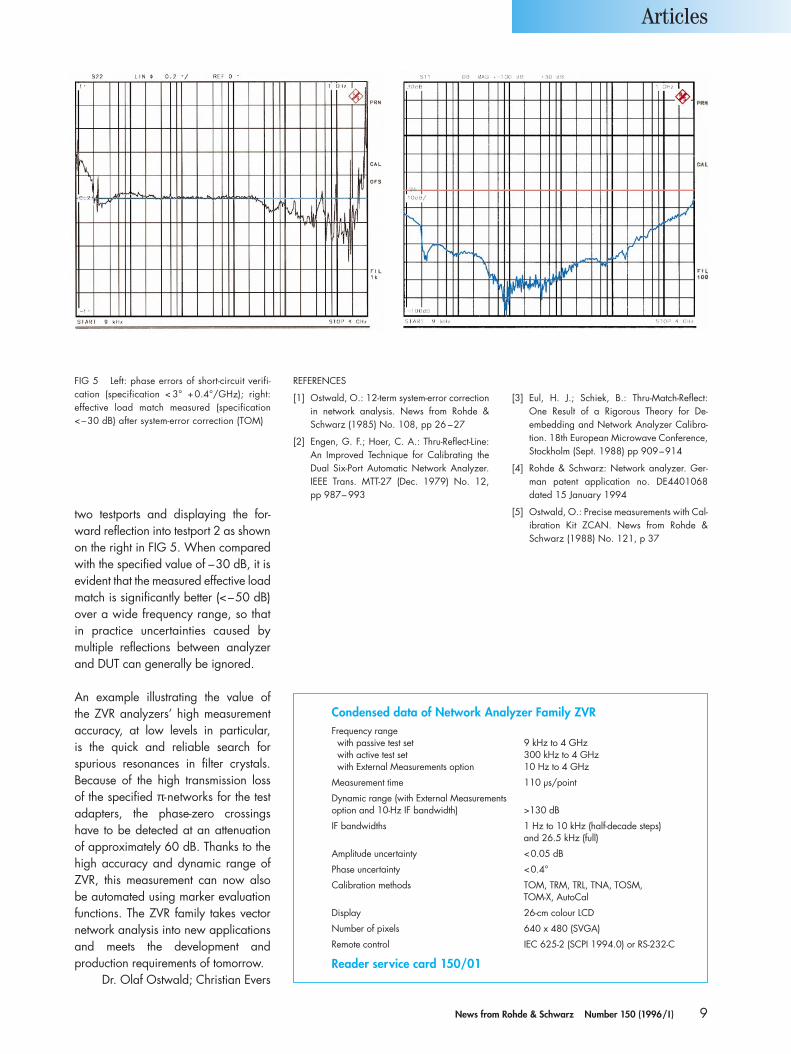
two testports and displaying the for-ward reflection into testport 2 as shownon the right in FIG 5. When comparedwith the specified value of –30 dB, it isevident that the measured effective loadmatch is significantly better (<–50 dB)over a wide frequency range, so that in practice uncertainties caused by multiple reflections between analyzerand DUT can generally be ignored.
An example illustrating the value of the ZVR analyzers’ high measurementaccuracy, at low levels in particular, is the quick and reliable search for spurious resonances in filter crystals.Because of the high transmission loss of the specified π-networks for the testadapters, the phase-zero crossingshave to be detected at an attenuation of approximately 60 dB. Thanks to thehigh accuracy and dynamic range ofZVR, this measurement can now alsobe automated using marker evaluationfunctions. The ZVR family takes vectornetwork analysis into new applicationsand meets the development and production requirements of tomorrow.
Dr. Olaf Ostwald; Christian Evers
REFERENCES
[1] Ostwald, O.: 12-term system-error correctionin network analysis. News from Rohde &Schwarz (1985) No. 108, pp 26 –27
[2] Engen, G. F.; Hoer, C. A.: Thru-Reflect-Line: An Improved Technique for Calibrating theDual Six-Port Automatic Network Analyzer.IEEE Trans. MTT-27 (Dec. 1979) No. 12, pp 987– 993
[3] Eul, H. J.; Schiek, B.: Thru-Match-Reflect:One Result of a Rigorous Theory for De-embedding and Network Analyzer Calibra-tion. 18th European Microwave Conference,Stockholm (Sept. 1988) pp 909–914
[4] Rohde & Schwarz: Network analyzer. Ger-man patent application no. DE4401068 dated 15 January 1994
[5] Ostwald, O.: Precise measurements with Cal-ibration Kit ZCAN. News from Rohde &Schwarz (1988) No. 121, p 37
Articles
FIG 5 Left: phase errors of short-circuit verifi-cation (specification < 3° +0.4°/GHz); right: effective load match measured (specification<–30 dB) after system-error correction (TOM)
Condensed data of Network Analyzer Family ZVRFrequency rangewith passive test set 9 kHz to 4 GHzwith active test set 300 kHz to 4 GHzwith External Measurements option 10 Hz to 4 GHz
Measurement time 110 µs/point
Dynamic range (with External Measurements option and 10-Hz IF bandwidth) >130 dB
IF bandwidths 1 Hz to 10 kHz (half-decade steps)and 26.5 kHz (full)
Amplitude uncertainty <0.05 dB
Phase uncertainty <0.4°
Calibration methods TOM, TRM, TRL, TNA, TOSM, TOM-X, AutoCal
Display 26-cm colour LCD
Number of pixels 640 x 480 (SVGA)
Remote control IEC 625-2 (SCPI 1994.0) or RS-232-C
Reader service card 150/01
10 News from Rohde & Schwarz Number 150 (1996/I )
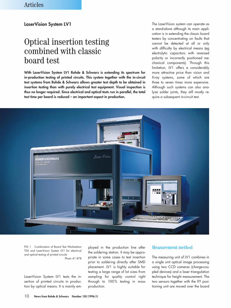
LaserVision System LV1 tests the in-sertion of printed circuits in produc-tion by optical means. It is mainly em-
ployed in the production line after the soldering station. It may be appro-priate in some cases to test insertionprior to soldering directly after SMDplacement. LV1 is highly suitable fortesting a large range of lot sizes fromsampling for quality control rightthrough to 100% testing in mass production.
Measurement method
The measuring unit of LV1 combines ina single unit optical image processingusing two CCD cameras (charge-cou-pled devices) and a laser triangulationtechnique for height measurement. Thetwo sensors together with the XY posi-tioning unit are moved over the board
Articles
The LaserVision system can operate asa stand-alone although its main appli-cation is in extending the classic boardtesters by concentrating on faults thatcannot be detected at all or only with difficulty by electrical means (egelectrolytic capacitors with reversed polarity or incorrectly positioned me-chanical components). Through this limitation, LV1 offers a considerablymore attractive price than vision and X-ray systems, some of which are three to seven times more expensive. Although such systems can also ana-lyze solder joints, they still mostly re-quire a subsequent in-circuit test.
LaserVision System LV1
Optical insertion testingcombined with classicboard testWith LaserVision System LV1 Rohde & Schwarz is extending its spectrum for in-production testing of printed circuits. This system together with the in-circuit test systems from Rohde & Schwarz allows greater test depth to be obtained ininsertion testing than with purely electrical test equipment. Visual inspection isthus no longer required. Since electrical and optical tests run in parallel, the totaltest time per board is reduced – an important aspect in production.
FIG 1 Combination of Board Test WorkstationTSA and LaserVision System LV1 for electricaland optical testing of printed circuits
Photo 41 878
11News from Rohde & Schwarz Number 150 (1996/I )
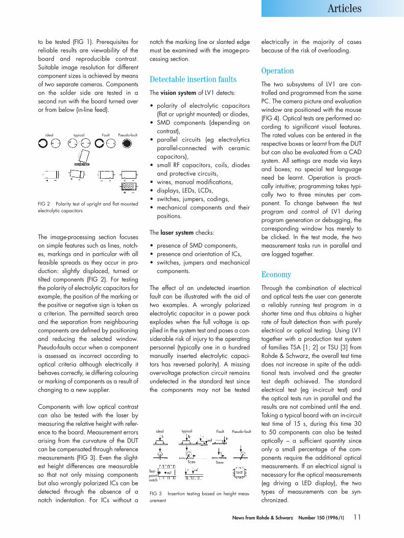
The image-processing section focuseson simple features such as lines, notch-es, markings and in particular with allfeasible spreads as they occur in pro-duction: slightly displaced, turned or tilted components (FIG 2). For testingthe polarity of electrolytic capacitors forexample, the position of the marking orthe positive or negative sign is taken asa criterion. The permitted search areaand the separation from neighbouringcomponents are defined by positioningand reducing the selected window.Pseudo-faults occur when a componentis assessed as incorrect according tooptical criteria although electrically itbehaves correctly, ie differing colouringor marking of components as a result ofchanging to a new supplier.
Components with low optical contrastcan also be tested with the laser bymeasuring the relative height with refer-ence to the board. Measurement errorsarising from the curvature of the DUTcan be compensated through referencemeasurements (FIG 3). Even the slight-est height differences are measurableso that not only missing components but also wrongly polarized ICs can bedetected through the absence of anotch indentation. For ICs without a
notch the marking line or slanted edgemust be examined with the image-pro-cessing section.
Detectable insertion faults
The vision system of LV1 detects:
• polarity of electrolytic capacitors(flat or upright mounted) or diodes,
• SMD components (depending oncontrast),
• parallel circuits (eg electrolyticsparallel-connected with ceramic capacitors),
• small RF capacitors, coils, diodesand protective circuits,
• wires, manual modifications,• displays, LEDs, LCDs,• switches, jumpers, codings,• mechanical components and their
positions.
The laser system checks:
• presence of SMD components,• presence and orientation of ICs,• switches, jumpers and mechanical
components.
The effect of an undetected insertionfault can be illustrated with the aid oftwo examples. A wrongly polarizedelectrolytic capacitor in a power packexplodes when the full voltage is ap-plied in the system test and poses a con-siderable risk of injury to the operatingpersonnel (typically one in a hundredmanually inserted electrolytic capaci-tors has reversed polarity). A missingovervoltage protection circuit remainsundetected in the standard test since the components may not be tested
electrically in the majority of cases because of the risk of overloading.
Operation
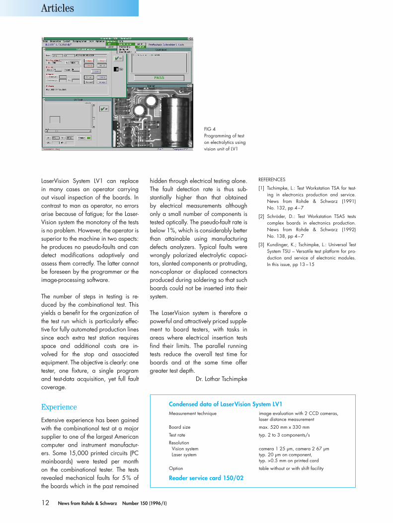
The two subsystems of LV1 are con-trolled and programmed from the samePC. The camera picture and evaluationwindow are positioned with the mouse(FIG 4). Optical tests are performed ac-cording to significant visual features.The rated values can be entered in therespective boxes or learnt from the DUTbut can also be evaluated from a CADsystem. All settings are made via keysand boxes; no special test languageneed be learnt. Operation is practi-cally intuitive; programming takes typi-cally two to three minutes per com-ponent. To change between the test program and control of LV1 during program generation or debugging, thecorresponding window has merely tobe clicked. In the test mode, the twomeasurement tasks run in parallel andare logged together.
Economy
Through the combination of electricaland optical tests the user can generatea reliably running test program in ashorter time and thus obtains a higherrate of fault detection than with purelyelectrical or optical testing. Using LV1together with a production test systemof families TSA [1; 2] or TSU [3] fromRohde & Schwarz, the overall test timedoes not increase in spite of the addi-tional tests involved and the greater test depth achieved. The standardelectrical test (eg in-circuit test) and the optical tests run in parallel and the results are not combined until the end.Taking a typical board with an in-circuittest time of 15 s, during this time 30 to 50 components can also be testedoptically – a sufficient quantity since only a small percentage of the com-ponents require the additional opticalmeasurements. If an electrical signal isnecessary for the optical measurements(eg driving a LED display), the twotypes of measurements can be syn-chronized.
Articles
to be tested (FIG 1). Prerequisites for reliable results are viewability of theboard and reproducible contrast. Suitable image resolution for differentcomponent sizes is achieved by meansof two separate cameras. Componentson the solder side are tested in a second run with the board turned overor from below (in-line feed).
FIG 2 Polarity test of upright and flat mountedelectrolytic capacitors
FIG 3 Insertion testing based on height meas-urement
ideal typical Fault Pseudo-fault
Test-pointnotch
ideal typical Fault Pseudo-fault
12 News from Rohde & Schwarz Number 150 (1996/I )
LaserVision System LV1 can replace in many cases an operator carrying out visual inspection of the boards. Incontrast to man as operator, no errorsarise because of fatigue; for the Laser-Vision system the monotony of the testsis no problem. However, the operator issuperior to the machine in two aspects:he produces no pseudo-faults and candetect modifications adaptively and assess them correctly. The latter cannotbe foreseen by the programmer or theimage-processing software.
The number of steps in testing is re-duced by the combinational test. Thisyields a benefit for the organization ofthe test run which is particularly effec-tive for fully automated production linessince each extra test station requiresspace and additional costs are in-volved for the stop and associatedequipment. The objective is clearly: onetester, one fixture, a single programand test-data acquisition, yet full faultcoverage.
Experience
Extensive experience has been gainedwith the combinational test at a majorsupplier to one of the largest Americancomputer and instrument manufactur-ers. Some 15,000 printed circuits (PCmainboards) were tested per month on the combinational tester. The tests revealed mechanical faults for 5% ofthe boards which in the past remained
hidden through electrical testing alone.The fault detection rate is thus sub-stantially higher than that obtained by electrical measurements althoughonly a small number of components istested optically. The pseudo-fault rate isbelow 1%, which is considerably betterthan attainable using manufacturingdefects analyzers. Typical faults werewrongly polarized electrolytic capaci-tors, slanted components or protruding,non-coplanar or displaced connectorsproduced during soldering so that suchboards could not be inserted into theirsystem.
The LaserVision system is therefore apowerful and attractively priced supple-ment to board testers, with tasks in areas where electrical insertion testsfind their limits. The parallel runningtests reduce the overall test time forboards and at the same time offergreater test depth.
Dr. Lothar Tschimpke
Articles
FIG 4Programming of teston electrolytics usingvision unit of LV1
Condensed data of LaserVision System LV1Measurement technique image evaluation with 2 CCD cameras,
laser distance measurement
Board size max. 520 mm x 330 mm
Test rate typ. 2 to 3 components/s
ResolutionVision system camera 1 25 µm, camera 2 67 µmLaser system typ. 20 µm on component,
typ. >0.5 mm on printed card
Option table without or with shift facility
Reader service card 150/02
REFERENCES
[1] Tschimpke, L.: Test Workstation TSA for test-ing in electronics production and service.News from Rohde & Schwarz (1991) No. 132, pp 4–7
[2] Schröder, D.: Test Workstation TSAS testscomplex boards in electronics production.News from Rohde & Schwarz (1992) No. 138, pp 4–7
[3] Kundinger, K.; Tschimpke, L.: Universal TestSystem TSU – Versatile test platform for pro-duction and service of electronic modules. In this issue, pp 13 –15
13News from Rohde & Schwarz Number 150 (1996/I )
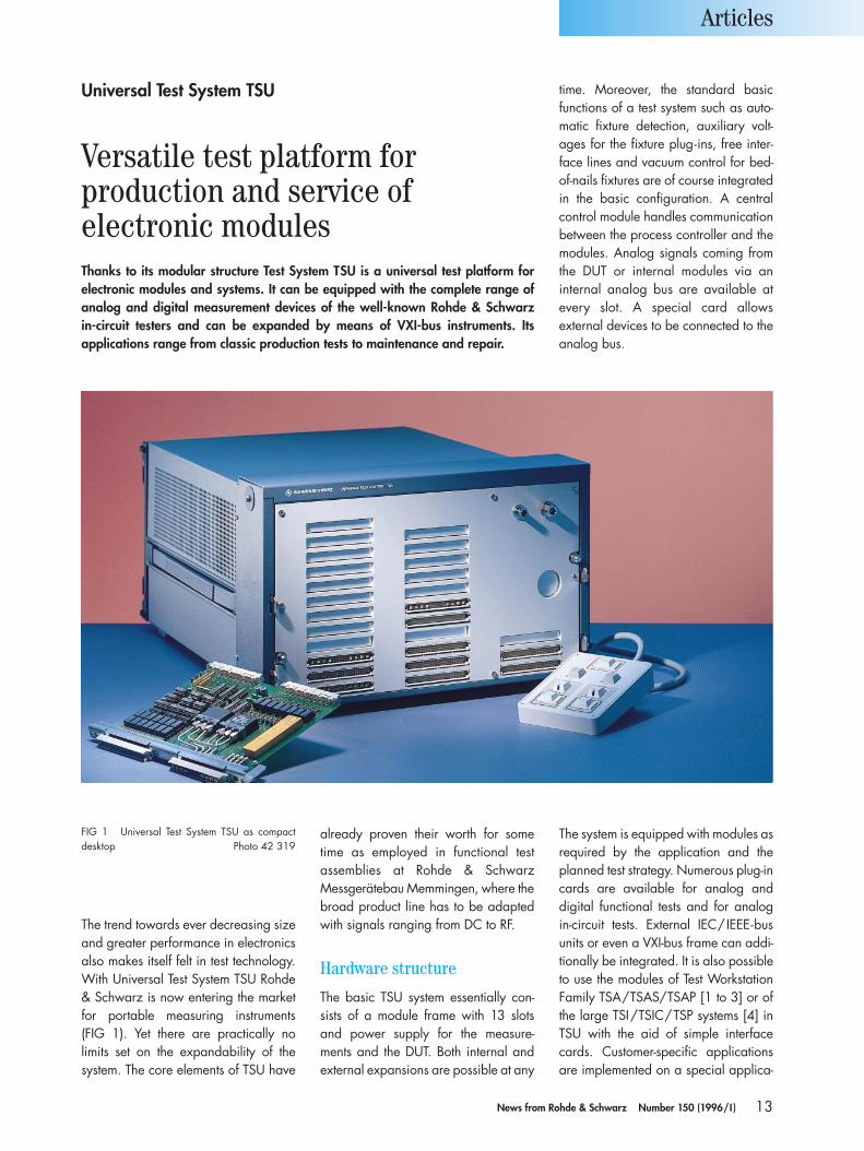
The trend towards ever decreasing sizeand greater performance in electronicsalso makes itself felt in test technology.With Universal Test System TSU Rohde& Schwarz is now entering the marketfor portable measuring instruments (FIG 1). Yet there are practically no limits set on the expandability of thesystem. The core elements of TSU have
already proven their worth for sometime as employed in functional test assemblies at Rohde & Schwarz Messgerätebau Memmingen, where thebroad product line has to be adaptedwith signals ranging from DC to RF.
Hardware structure
The basic TSU system essentially con-sists of a module frame with 13 slotsand power supply for the measure-ments and the DUT. Both internal andexternal expansions are possible at any
The system is equipped with modules asrequired by the application and theplanned test strategy. Numerous plug-incards are available for analog and digital functional tests and for analogin-circuit tests. External IEC/IEEE-busunits or even a VXI-bus frame can addi-tionally be integrated. It is also possibleto use the modules of Test WorkstationFamily TSA/TSAS/TSAP [1 to 3] or ofthe large TSI/TSIC/TSP systems [4] inTSU with the aid of simple interfacecards. Customer-specific applicationsare implemented on a special applica-
Articles
time. Moreover, the standard basicfunctions of a test system such as auto-matic fixture detection, auxiliary volt-ages for the fixture plug-ins, free inter-face lines and vacuum control for bed-of-nails fixtures are of course integratedin the basic configuration. A centralcontrol module handles communicationbetween the process controller and themodules. Analog signals coming fromthe DUT or internal modules via aninternal analog bus are available atevery slot. A special card allows external devices to be connected to theanalog bus.
FIG 1 Universal Test System TSU as compactdesktop Photo 42 319
Universal Test System TSU
Versatile test platform forproduction and service of electronic modulesThanks to its modular structure Test System TSU is a universal test platform forelectronic modules and systems. It can be equipped with the complete range ofanalog and digital measurement devices of the well-known Rohde & Schwarz in-circuit testers and can be expanded by means of VXI-bus instruments. Its applications range from classic production tests to maintenance and repair.
14 News from Rohde & Schwarz Number 150 (1996/I )
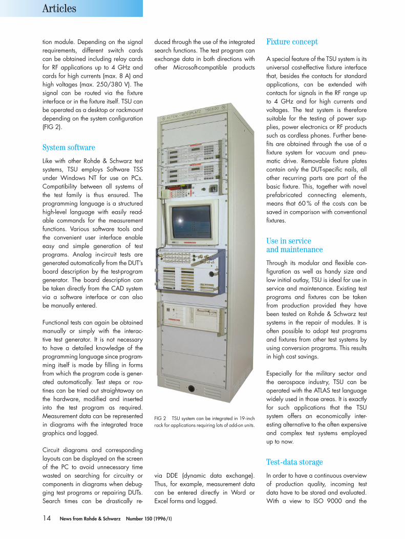
tion module. Depending on the signalrequirements, different switch cardscan be obtained including relay cardsfor RF applications up to 4 GHz andcards for high currents (max. 8 A) andhigh voltages (max. 250/380 V). Thesignal can be routed via the fixtureinterface or in the fixture itself. TSU canbe operated as a desktop or rackmountdepending on the system configuration(FIG 2).
System software
Like with other Rohde & Schwarz testsystems, TSU employs Software TSSunder Windows NT for use on PCs.Compatibility between all systems ofthe test family is thus ensured. The programming language is a structuredhigh-level language with easily read-able commands for the measurementfunctions. Various software tools andthe convenient user interface enableeasy and simple generation of test programs. Analog in-circuit tests aregenerated automatically from the DUT’sboard description by the test-programgenerator. The board description canbe taken directly from the CAD systemvia a software interface or can also be manually entered.
Functional tests can again be obtainedmanually or simply with the interac-tive test generator. It is not necessary to have a detailed knowledge of the programming language since program-ming itself is made by filling in formsfrom which the program code is gener-ated automatically. Test steps or rou-tines can be tried out straightaway onthe hardware, modified and insertedinto the test program as required.Measurement data can be representedin diagrams with the integrated tracegraphics and logged.
Circuit diagrams and correspondinglayouts can be displayed on the screenof the PC to avoid unnecessary timewasted on searching for circuitry orcomponents in diagrams when debug-ging test programs or repairing DUTs.Search times can be drastically re-
via DDE (dynamic data exchange).Thus, for example, measurement datacan be entered directly in Word or Excel forms and logged.
Fixture concept
A special feature of the TSU system is itsuniversal cost-effective fixture interfacethat, besides the contacts for standardapplications, can be extended withcontacts for signals in the RF range upto 4 GHz and for high currents and voltages. The test system is thereforesuitable for the testing of power sup-plies, power electronics or RF productssuch as cordless phones. Further bene-fits are obtained through the use of afixture system for vacuum and pneu-matic drive. Removable fixture platescontain only the DUT-specific nails, allother recurring parts are part of the basic fixture. This, together with novelprefabricated connecting elements,means that 60 % of the costs can besaved in comparison with conventionalfixtures.
Use in service and maintenance
Through its modular and flexible con-figuration as well as handy size andlow initial outlay, TSU is ideal for use inservice and maintenance. Existing testprograms and fixtures can be takenfrom production provided they havebeen tested on Rohde & Schwarz testsystems in the repair of modules. It is often possible to adopt test programsand fixtures from other test systems byusing conversion programs. This resultsin high cost savings.
Especially for the military sector and the aerospace industry, TSU can be operated with the ATLAS test languagewidely used in those areas. It is exactlyfor such applications that the TSUsystem offers an economically inter-esting alternative to the often expensiveand complex test systems employed up to now.
Test-data storage
In order to have a continuous overviewof production quality, incoming testdata have to be stored and evaluated.With a view to ISO 9000 and the
Articles
duced through the use of the integratedsearch functions. The test program canexchange data in both directions withother Microsoft-compatible products
FIG 2 TSU system can be integrated in 19-inchrack for applications requiring lots of add-on units.
15News from Rohde & Schwarz Number 150 (1996/I )
product liability law, the history of aproduct from its production to service isof importance. In the long run, highproduct quality can only be guaranteedthrough systematic documentation of allwork carried out during its life cycle.
Klaus Kundiger;Dr. Lothar Tschimpke
Articles
Test hint
Condensed data of Universal Test System TSUTest methods analog in-circuit test, analog IC check, analog/digital
functional test, emulation test, boundary scan test, LaserVision test
Analog tests various signal sources and measuring instruments for integration as modules or external units, internalanalog bus, instrument multiplexer for external units,signal relays for frequency range DC to 4 GHz, number of pins expandable to 576
Digital test module for static test (data rate max. 50 kHz) or dynamic test (data rate max. 10 MHz), level rangeup to ±30 V, number of pins expandable to 256
Computer standard PC with Windows NT operating system
Software TSS Windows, interactive test generator, trace graphics, quality management, paperless repair,graphic debugging software, graphic repair station,CAD/CAE link
Reader service card 150/03
SMP NRVD
Sensor(eg NRV-Z4)
Installing directional antennas for microwave WLANs
Life without PC networking is hard to imagine inthe offices and labs of modern enterprises as itopens up communication facilities for everyone.Up to now most networks have been based on coaxial cables, which are expensive to lay.Thanks to drops in the prices of integrated cir-cuits, wireless local area networks (WLANs) arebeing seen in a more favourable light because ofthe economic advantage. It is also obvious thatportable computers like notebooks can be net-worked in this way, but the same also applies towhole buildings and remote factory sites whichcould have a wireless connection with the mainnetwork. This is also a sound approach for coun-tries with an infrastructure that is still being expanded. Short-hop microwave links on the2.45 GHz ISM frequency are ideal for this pur-pose. Spread-spectrum methods such as frequen-cy hopping or the direct-sequence spread-spec-trum method make it possible to operate severaladjacent networks on the same frequency withoutmutual interference or any risk of eavesdropping.
When such an approach is used, energy is transmitted over a large frequency band (approx.2 MHz) and the signal cannot be detected with
conventional RF measurement devices like powermeters or spectrum analyzers. This does not exactly make life easy for someone installing radio-link hops, because the antennas of thetransceiver stations have to be aligned spot on.“Eyeballing” may work for short distances, but another more “ far-sighted” method has to befound for hop lengths in the km range.
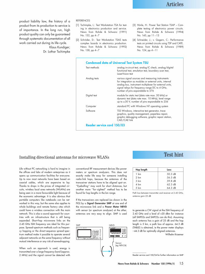
If the transceivers are replaced (as shown in theFIG) by a Signal Generator SMP at one end ofthe microwave link and a Power Meter NRVDwith sensor (or spectrum analyzer) at the other,antennas are very easy to align. SMP is used
to generate a CW signal at the ISM frequency of2.45 GHz and a level of +20 dBm for instance (all SMP02s and SMP22s can do this). Assumingeach antenna has a gain of 25 dB and the hoplength is 5 km, a path loss of approx. 64.3 dB(TABLE) is obtained, ie the power meter displays –44.3 dB for optimally aligned antennas.
Wilhelm Kraemer
Reader service card 150/04 for further information on SMP
Path loss between transmitter and receiver at 2.45 GHz,antenna gain 25 dB
Hop length Loss
1 km 50.3 dB2 km 56.3 dB3 km 59.8 dB4 km 62.3 dB5 km 64.3 dB
REFERENCES
[1] Tschimpke, L.: Test Workstation TSA for test-ing in electronics production and service.News from Rohde & Schwarz (1991) No. 132, pp 4–7
[2] Schröder, D.: Test Workstation TSAS testscomplex boards in electronics production.News from Rohde & Schwarz (1992) No. 138, pp 4–7
[3] Hönle, H.: Power Test Station TSAP – Com-plete testing of electronics power circuits.News from Rohde & Schwarz (1994) No. 145, pp 11 –13
[4] Schneider, J.; v. Gagern, C.: Performancetests on printed circuits using TSP and CATE.News from Rohde & Schwarz (1989) No. 124, pp 4 –11
16 News from Rohde & Schwarz Number 150 (1996/I )
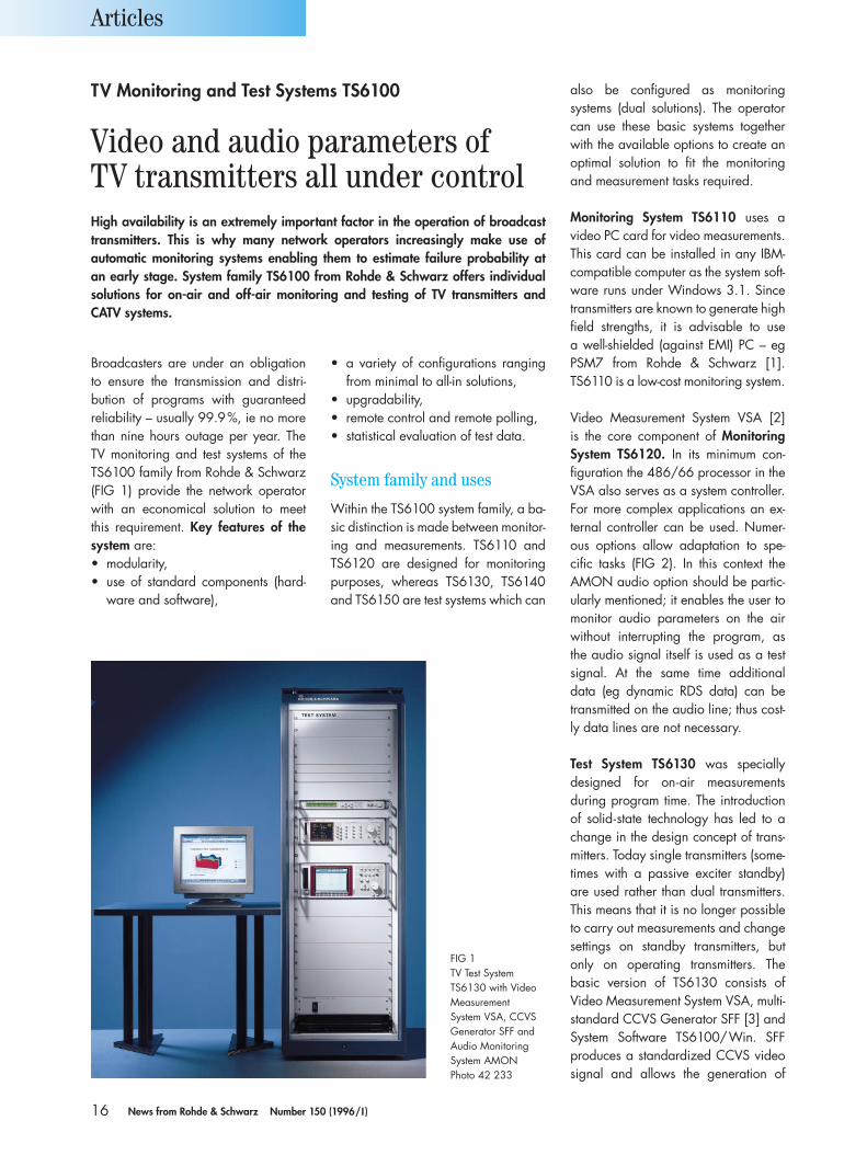
Broadcasters are under an obligationto ensure the transmission and distri-bution of programs with guaranteed reliability – usually 99.9%, ie no morethan nine hours outage per year. TheTV monitoring and test systems of theTS6100 family from Rohde & Schwarz(FIG 1) provide the network operatorwith an economical solution to meet this requirement. Key features of thesystem are:• modularity,• use of standard components (hard-
ware and software),
• a variety of configurations rangingfrom minimal to all-in solutions,
• upgradability,• remote control and remote polling,• statistical evaluation of test data.
System family and uses
Within the TS6100 system family, a ba-sic distinction is made between monitor-ing and measurements. TS6110 andTS6120 are designed for monitoringpurposes, whereas TS6130, TS6140and TS6150 are test systems which can
also be configured as monitoringsystems (dual solutions). The operatorcan use these basic systems togetherwith the available options to create anoptimal solution to fit the monitoringand measurement tasks required.
Monitoring System TS6110 uses a video PC card for video measurements.This card can be installed in any IBM-compatible computer as the system soft-ware runs under Windows 3.1. Sincetransmitters are known to generate highfield strengths, it is advisable to use a well-shielded (against EMI) PC – egPSM7 from Rohde & Schwarz [1].TS6110 is a low-cost monitoring system.
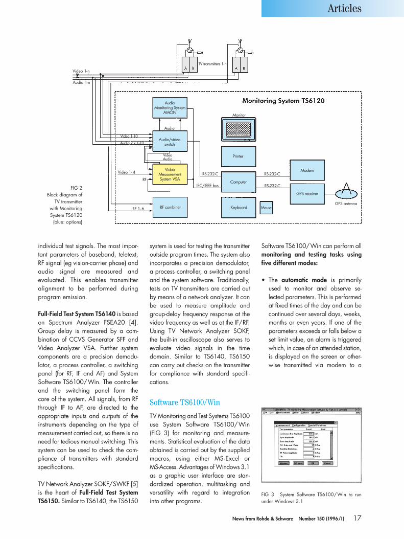
Video Measurement System VSA [2] is the core component of MonitoringSystem TS6120. In its minimum con-figuration the 486/66 processor in theVSA also serves as a system controller.For more complex applications an ex-ternal controller can be used. Numer-ous options allow adaptation to spe-cific tasks (FIG 2). In this context the AMON audio option should be partic-ularly mentioned; it enables the user tomonitor audio parameters on the airwithout interrupting the program, as the audio signal itself is used as a testsignal. At the same time additionaldata (eg dynamic RDS data) can betransmitted on the audio line; thus cost-ly data lines are not necessary.
Test System TS6130 was specially designed for on-air measurements during program time. The introductionof solid-state technology has led to achange in the design concept of trans-mitters. Today single transmitters (some-times with a passive exciter standby)are used rather than dual transmitters.This means that it is no longer possibleto carry out measurements and changesettings on standby transmitters, but only on operating transmitters. The basic version of TS6130 consists of Video Measurement System VSA, multi-standard CCVS Generator SFF [3] andSystem Software TS6100/Win. SFFproduces a standardized CCVS videosignal and allows the generation of
Articles
TV Monitoring and Test Systems TS6100
Video and audio parameters of TV transmitters all under controlHigh availability is an extremely important factor in the operation of broadcasttransmitters. This is why many network operators increasingly make use of automatic monitoring systems enabling them to estimate failure probability at an early stage. System family TS6100 from Rohde & Schwarz offers individualsolutions for on-air and off-air monitoring and testing of TV transmitters and CATV systems.
FIG 1TV Test SystemTS6130 with VideoMeasurement System VSA, CCVSGenerator SFF andAudio MonitoringSystem AMONPhoto 42 233
17News from Rohde & Schwarz Number 150 (1996/I )
individual test signals. The most impor-tant parameters of baseband, teletext,RF signal (eg vision-carrier phase) andaudio signal are measured and evaluated. This enables transmitteralignment to be performed during program emission.
Full-Field Test System TS6140 is basedon Spectrum Analyzer FSEA20 [4].Group delay is measured by a com-bination of CCVS Generator SFF andVideo Analyzer VSA. Further systemcomponents are a precision demodu-lator, a process controller, a switchingpanel (for RF, IF and AF) and SystemSoftware TS6100/Win. The controllerand the switching panel form the core of the system. All signals, from RFthrough IF to AF, are directed to the appropriate inputs and outputs of theinstruments depending on the type ofmeasurement carried out, so there is noneed for tedious manual switching. Thissystem can be used to check the com-pliance of transmitters with standardspecifications.
TV Network Analyzer SOKF/SWKF [5]is the heart of Full-Field Test SystemTS6150. Similar to TS6140, the TS6150
system is used for testing the transmitteroutside program times. The system alsoincorporates a precision demodulator,a process controller, a switching paneland the system software. Traditionally,tests on TV transmitters are carried outby means of a network analyzer. It canbe used to measure amplitude andgroup-delay frequency response at thevideo frequency as well as at the IF/RF.Using TV Network Analyzer SOKF, the built-in oscilloscope also serves toevaluate video signals in the time domain. Similar to TS6140, TS6150can carry out checks on the transmitterfor compliance with standard specifi-cations.
Software TS6100/Win
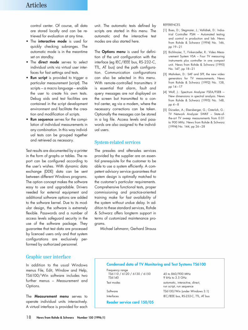
TV Monitoring and Test Systems TS6100use System Software TS6100/Win (FIG 3) for monitoring and measure-ments. Statistical evaluation of the dataobtained is carried out by the suppliedmacros, using either MS-Excel or MS-Access. Advantages of Windows 3.1as a graphic user interface are stan-dardized operation, multitasking andversatility with regard to integrationinto other programs.
Software TS6100/Win can perform allmonitoring and testing tasks usingfive different modes:
• The automatic mode is primarilyused to monitor and observe se-lected parameters. This is performedat fixed times of the day and can becontinued over several days, weeks,months or even years. If one of theparameters exceeds or falls below aset limit value, an alarm is triggeredwhich, in case of an attended station,is displayed on the screen or other-wise transmitted via modem to a
Articles
FIG 3 System Software TS6100/Win to run under Windows 3.1
Video 1-n
Audio 1-n
AudioMonitoring System
AMON
Audio
Audio/videoswitch
Video 1-10
Audio 2 x 1-10
VideoAudio
Video 1- 4
RF
VideoMeasurementSystem VSA
RF combinerRF 1- 6
RS-232-C RS-232-C
RS-232-CIEC/IEEE busComputer
Keyboard
Printer
Mouse
Modem
GPS receiver
GPS antenna
Monitor
TV transmitters 1-n
FIG 2Block diagram of
TV transmitter with Monitoring System TS6120
(blue: options)
18 News from Rohde & Schwarz Number 150 (1996/I )
control center. Of course, all dataare stored locally and can be re-trieved for evaluation at any time.
• The interactive mode is used forquickly checking subranges. The automatic mode is in the meantimeset on standby.
• The direct mode serves to select individual units via virtual user inter-faces for fast settings and tests.
• Run script is provided to trigger aparticular measurement (script). Thescripts – a macro language – enablethe user to create his own tests. Debug aids and test facilities arecontained in the script developmentenvironment and facilitate the crea-tion and modification of scripts.
• Run sequence serves for the compi-lation of individual measurements inany combination. In this way individ-ual tests can be grouped togetherand retrieved as necessary.
Test results are documented by a printerin the form of graphs or tables. The re-port can be configured according tothe user’s wishes. With dynamic dataexchange (DDE) data can be sentbetween different Windows programs.The option concept makes the softwareeasy to use and upgradable. Driversneeded for external equipment and additional software options are addedto the software kernel. Due to its mod-ular design, the software is extremelyflexible. Passwords and a number ofaccess levels safeguard security in theuse of the software package. Theyguarantee that test data are processedby licenced users only and that systemconfigurations are exclusively per-formed by authorized personnel.
Graphic user interface
In addition to the usual Windows menus File, Edit, Window and Help,TS6100/Win software includes twofurther menus – Measurement and Options.
The Measurement menu serves to operate individual units interactively. A virtual interface is provided for each
unit. The automatic tests defined byscripts are started in this menu. The automatic and the interactive testmodes are also started here.
The Options menu is used for defini-tion of the unit configuration with theinterface (eg IEC/IEEE bus, RS-232-C,TTL, AT bus) and the path configura-tion. Communication configurationscan also be selected in this menu. With remote-controlled transmitters it is essential that alarm, fault and query messages are not displayed onthe screen but transmitted to a con-trol center, eg via a modem, where the necessary corrections can be taken.Optionally the messages can be storedin a log file. Access levels and pass-words are also assigned to the individ-ual users.
System-related services
The presales and aftersales servicesprovided by the supplier are an essen-tial prerequisite for the customer to beable to use a system efficiently. A com-petent advisory service guarantees thatsystem design is optimally matched tothe customer’s particular requirements.Comprehensive functional tests, propercommissioning and practice-orientedtraining make for fast availability of the system without undue delay. In ad-dition to these standard services, Rohde& Schwarz offers longterm support interms of customized maintenance pro-grams.
Michael Lehmann; Gerhard Strauss
REFERENCES
[1] Bues, D.; Stegmaier, J.; Vahldiek, D.: Indus-trial Controller PSM – Automated testing and control in production and lab. Newsfrom Rohde & Schwarz (1994) No. 146, pp 19– 21
[2] Bichlmaier, T.; Finkenzeller, R.: Video Meas-urement System VSA – Four TV measuring instruments plus controller in one compactunit. News from Rohde & Schwarz (1995)No. 147, pp 18–21
[3] Mahnken, D.: SAF and SFF, the new videogenerators for TV measurements. News from Rohde & Schwarz (1992) No. 138, pp 14 –17
[4] Wolf, J.: Spectrum Analyzer FSEA/FSEB –-New dimensions in spectral analysis. Newsfrom Rohde & Schwarz (1995) No. 148, pp 4 – 8
[5] Dürselen, A.; Ebersberger, G.; Osterloh, G.:TV Network Analyzer SWKF – State-of-the-art TV sweep measurements from 0.01 to 900 MHz. News from Rohde & Schwarz(1994) No. 144, pp 26 –28
Articles
Condensed data of TV Monitoring and Test Systems TS6100Frequency range
TS6110 / 6120 / 6130 / 6150 45 to 860/900 MHzTS6140 9 kHz to 3.5 GHz
Test modes automatic, interactive, direct, run script, run sequence
Software TS6100/Win (under Windows 3.1)
Interfaces IEC/IEEE bus, RS-232-C, TTL, AT bus
Reader service card 150/05
19News from Rohde & Schwarz Number 150 (1996/I )
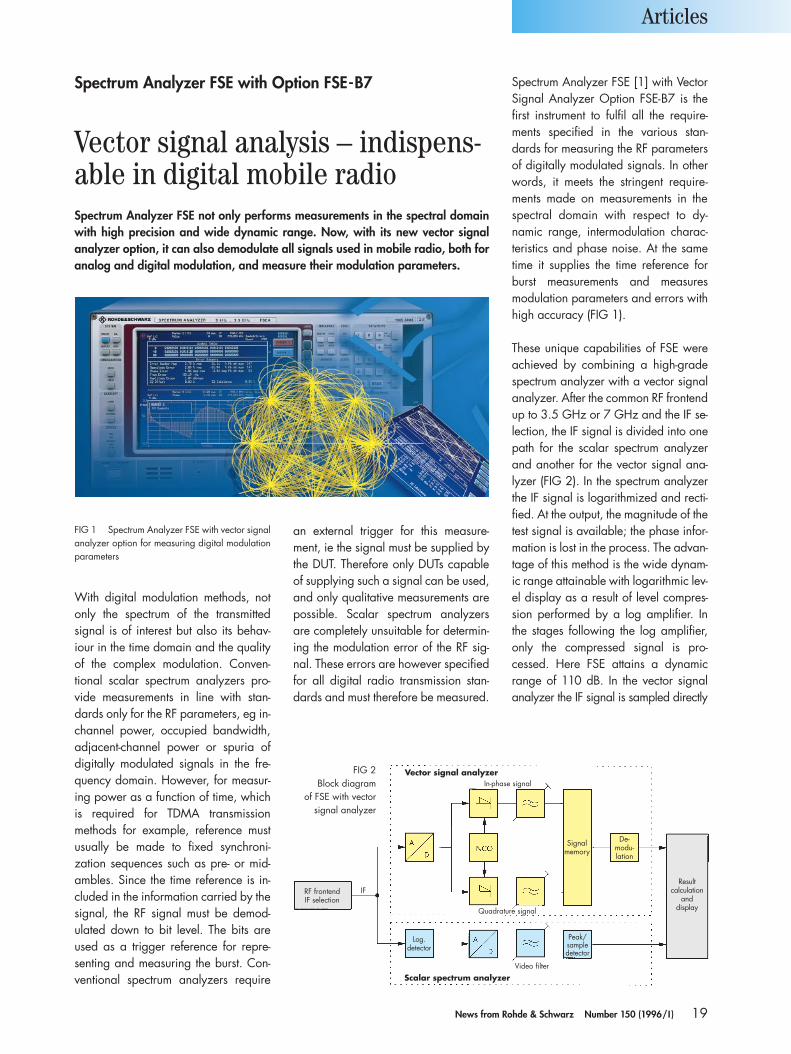
With digital modulation methods, notonly the spectrum of the transmitted signal is of interest but also its behav-iour in the time domain and the qualityof the complex modulation. Conven-tional scalar spectrum analyzers pro-vide measurements in line with stan-dards only for the RF parameters, eg in-channel power, occupied bandwidth,adjacent-channel power or spuria ofdigitally modulated signals in the fre-quency domain. However, for measur-ing power as a function of time, whichis required for TDMA transmissionmethods for example, reference mustusually be made to fixed synchroni-zation sequences such as pre- or mid-ambles. Since the time reference is in-cluded in the information carried by thesignal, the RF signal must be demod-ulated down to bit level. The bits areused as a trigger reference for repre-senting and measuring the burst. Con-ventional spectrum analyzers require
an external trigger for this measure-ment, ie the signal must be supplied bythe DUT. Therefore only DUTs capableof supplying such a signal can be used,and only qualitative measurements arepossible. Scalar spectrum analyzersare completely unsuitable for determin-ing the modulation error of the RF sig-nal. These errors are however specifiedfor all digital radio transmission stan-dards and must therefore be measured.
Spectrum Analyzer FSE [1] with VectorSignal Analyzer Option FSE-B7 is thefirst instrument to fulfil all the require-ments specified in the various stan-dards for measuring the RF parametersof digitally modulated signals. In otherwords, it meets the stringent require-ments made on measurements in thespectral domain with respect to dy-namic range, intermodulation charac-teristics and phase noise. At the sametime it supplies the time reference forburst measurements and measuresmodulation parameters and errors withhigh accuracy (FIG 1).
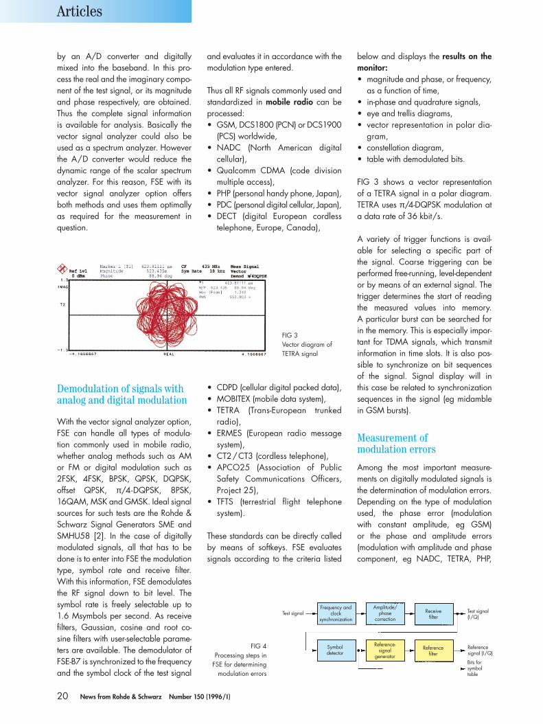
These unique capabilities of FSE wereachieved by combining a high-gradespectrum analyzer with a vector signalanalyzer. After the common RF frontendup to 3.5 GHz or 7 GHz and the IF se-lection, the IF signal is divided into onepath for the scalar spectrum analyzerand another for the vector signal ana-lyzer (FIG 2). In the spectrum analyzerthe IF signal is logarithmized and recti-fied. At the output, the magnitude of thetest signal is available; the phase infor-mation is lost in the process. The advan-tage of this method is the wide dynam-ic range attainable with logarithmic lev-el display as a result of level compres-sion performed by a log amplifier. Inthe stages following the log amplifier,only the compressed signal is pro-cessed. Here FSE attains a dynamicrange of 110 dB. In the vector signalanalyzer the IF signal is sampled directly
Articles
FIG 1 Spectrum Analyzer FSE with vector signalanalyzer option for measuring digital modulationparameters
In-phase signal
RF frontendIF selection
IF
Quadrature signal
Signalmemory
De-modu-lation
Peak/sampledetector
Log.detector
Video filter
Resultcalculation
anddisplay
Vector signal analyzer
Scalar spectrum analyzer
FIG 2Block diagram
of FSE with vector signal analyzer
Spectrum Analyzer FSE with Option FSE-B7
Vector signal analysis – indispens-able in digital mobile radioSpectrum Analyzer FSE not only performs measurements in the spectral domainwith high precision and wide dynamic range. Now, with its new vector signalanalyzer option, it can also demodulate all signals used in mobile radio, both foranalog and digital modulation, and measure their modulation parameters.
20 News from Rohde & Schwarz Number 150 (1996/I )
by an A/D converter and digitallymixed into the baseband. In this pro-cess the real and the imaginary compo-nent of the test signal, or its magnitudeand phase respectively, are obtained.Thus the complete signal information is available for analysis. Basically thevector signal analyzer could also beused as a spectrum analyzer. Howeverthe A/D converter would reduce the dynamic range of the scalar spectrumanalyzer. For this reason, FSE with itsvector signal analyzer option offersboth methods and uses them optimallyas required for the measurement inquestion.
and evaluates it in accordance with themodulation type entered.
Thus all RF signals commonly used andstandardized in mobile radio can beprocessed:• GSM, DCS1800 (PCN) or DCS1900
(PCS) worldwide,• NADC (North American digital
cellular),• Qualcomm CDMA (code division
multiple access),• PHP (personal handy phone, Japan),• PDC (personal digital cellular, Japan),• DECT (digital European cordless
telephone, Europe, Canada),
below and displays the results on themonitor:• magnitude and phase, or frequency,
as a function of time,• in-phase and quadrature signals,• eye and trellis diagrams,• vector representation in polar dia-
gram,• constellation diagram,• table with demodulated bits.
FIG 3 shows a vector representation of a TETRA signal in a polar diagram.TETRA uses π/4-DQPSK modulation ata data rate of 36 kbit/s.
A variety of trigger functions is avail-able for selecting a specific part of the signal. Coarse triggering can beperformed free-running, level-dependentor by means of an external signal. Thetrigger determines the start of readingthe measured values into memory. A particular burst can be searched forin the memory. This is especially impor-tant for TDMA signals, which transmitinformation in time slots. It is also pos-sible to synchronize on bit sequences of the signal. Signal display will in this case be related to synchronizationsequences in the signal (eg midamblein GSM bursts).
Measurement of modulation errors
Among the most important measure-ments on digitally modulated signals isthe determination of modulation errors.Depending on the type of modulationused, the phase error (modulation with constant amplitude, eg GSM) or the phase and amplitude errors (modulation with amplitude and phasecomponent, eg NADC, TETRA, PHP,
Articles
Demodulation of signals withanalog and digital modulation
With the vector signal analyzer option,FSE can handle all types of modula-tion commonly used in mobile radio,whether analog methods such as AMor FM or digital modulation such as 2FSK, 4FSK, BPSK, QPSK, DQPSK, offset QPSK, π/4-DQPSK, 8PSK, 16QAM, MSK and GMSK. Ideal signalsources for such tests are the Rohde &Schwarz Signal Generators SME andSMHU58 [2]. In the case of digitallymodulated signals, all that has to bedone is to enter into FSE the modulationtype, symbol rate and receive filter.With this information, FSE demodulatesthe RF signal down to bit level. The symbol rate is freely selectable up to1.6 Msymbols per second. As receivefilters, Gaussian, cosine and root co-sine filters with user-selectable parame-ters are available. The demodulator ofFSE-B7 is synchronized to the frequencyand the symbol clock of the test signal
• CDPD (cellular digital packed data),• MOBITEX (mobile data system),• TETRA (Trans-European trunked
radio),• ERMES (European radio message
system),• CT2/CT3 (cordless telephone),• APCO25 (Association of Public
Safety Communications Officers,Project 25),
• TFTS (terrestrial flight telephonesystem).
These standards can be directly calledby means of softkeys. FSE evaluates signals according to the criteria listed
FIG 3Vector diagram ofTETRA signal
FIG 4Processing steps in
FSE for determiningmodulation errors
Test signalFrequency and
clocksynchronization
Amplitude/phase
correctionReceive
filterTest signal(I/Q)
Symboldetector
Reference-signal
generator
Referencefilter
Referencesignal (I/Q)
Bits forsymboltable
21News from Rohde & Schwarz Number 150 (1996/I )
PDC) are of interest and specified in the relevant standards. For error cal-culation FSE generates the analog,ideally modulated signal in the base-band (I/Q level) from the demodulatedbit stream. FIG 4 shows the processingsteps.
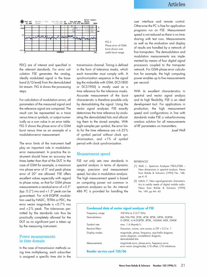
For calculation of modulation errors, allparameters of the measured signal andthe reference signal are compared. Theresult can be represented as a trace versus time or symbols, or output numer-ically as a sum value in an error table.FIG 5 shows the phase error of a GSMburst versus time as an example of amodulation-error measurement.
The error limits of the instrument itselfplay an important role in modulation-error measurement. In practice the in-strument should have an accuracy tentimes better than that of the DUT. In thecase of GSM for example, a maximumrms phase error of 5° and peak phaseerror of 20° are allowed. FSE offers excellent values especially with regardto phase noise, so that for GSM phasemeasurements a residual error of <0.5°(typ. 0.2°) rms and <1.5° peak can beguaranteed. For π/4-DQPSK modula-tion used by NADC, TETRA or PDC, theerror vector magnitude is <0.7% rmsand <2% peak. The tolerances per-mitted by the standards can thus bepractically completely allowed for theDUT as no significant part is taken upby the measuring instrument.
Power measurements in time domain
In the case of transmission methods us-ing time multiplexing, each subscriberis assigned a specific time slot in the
transmission channel. Timing is definedin the form of tolerance masks, whicheach transmitter must comply with. Asynchronization sequence in the signal(eg the midamble with GSM, DCS1800or DCS1900) is mostly used as a time reference for the tolerance masks.Accurate measurement of the burstcharacteristic is therefore possible onlyby demodulating the signal. Using thevector signal analyzer, FSE exactly determines the time reference by evalu-ating the demodulated bits and allocat-ing them to the stored samples. Witheight samples per symbol, the error lim-its for the time reference are <6.25%of symbol period without clock syn-chronization, and <1% of symbol period with clock synchronization.
Measurement speed
FSE not only sets new standards inspectral analysis in terms of dynamicrange, precision and measurementspeed, but also in modulation analysis.The high measurement speed is basedon computing power not common inspectrum analyzers so far. An internal486 PC is provided for handling the
user interface and remote control. Otherwise the PC is free for applicationprograms run on FSE. Measurementspeed is not reduced as there is no time-sharing with test runs. Measurements as well as the evaluation and display of results are handled by a network offive transputers. The demodulators andmodulation measurements are imple-mented by means of four digital signalprocessors coupled to the transputernetwork. For GSM phase-error calcula-tion for example, the high computingpower enables up to five measurementsper second.
With its excellent characteristics inspectral and vector signal analysis and its high flexibility, FSE is an idealdevelopment tool. For applications inproduction, the high measurementspeed and configurations in line withstandards make FSE a value-for-moneyone-box solution for all measurementsof RF parameters on transmitters.
Josef Wolf
Articles
FIG 5Phase error of GSMburst shown over useful burst range
Condensed data of vector signal analyzer of FSEFrequency range 100 kHz to 3.5/7 GHz
Demodulators AM/FM/PM, 2FSK, 4FSK, BPSK, QPSK, DQPSK, O-QPSK, π/4-DQPSK, 8PSK, 16QAM, MSK, GMSK
Symbol rate max. 1.6 Msymb/s
Receive filters Gaussian, cosine, root cosine, α /BT = 0.2 to 1
Display modes magnitude, phase, frequency, eye/trellis diagram,vector diagram, constellation diagram, demodulated bits
Measurements magnitude error, phase error, frequency error, error vector (magnitude), I/Q offset, I/Q imbalance
Reader service card 150/06
REFERENCES
[1] Wolf, J.: Spectrum Analyzer FSEA/FSEB –New dimensions in spectral analysis. Newsfrom Rohde & Schwarz (1995) No. 148, pp 4–8
[2] Lüttich, F.: New signal-generator characteris-tics to satisfy needs of digital mobile radio.News from Rohde & Schwarz (1995) No. 149, pp 44 –45

22 News from Rohde & Schwarz Number 150 (1996/I )
The Rohde & Schwarz doppler Direc-tion Finders PA010 and PA055 and theirmobile counterparts PA510 and PA555have for many years been a great suc-cess all over the world. It is in the natureof the doppler principle that the capa-bilities of these direction finders are lim-ited when it comes to intercepting veryshort signals as used in frequency hop-ping, burst and GSM transmissions. Foruncomplicated bearings on such signals,Rohde & Schwarz has developed a newgeneration of direction finders usingdigital signal processing: DDF0xS forfast scanning [1] and the brand-newDDF0xM mainly for monitoring tasks in
the frequency range 0.3 to 3000 MHz(FIG 1). DDF0xM direction finders canalso be used for scanning, the prob-ability of intercept being markedly higher than that of conventional direc-tion finders, which can process the sig-nal in only one channel at a time. Thedirection finders of the DDF family ana-lyze all signals within a frequency win-dow simultaneously with the selectedresolution. In the search and scanmodes the direction finders behave likeseveral DF units connected in parallel.
The DDF direction finders first deter-mine the complex voltages of the DF antenna and from these calculate theazimuth and, if desired, the elevation.The DF method used can be selected as required to match the task on hand.
• high flexibility with respect to antennageometry,
• in mobile use, very effective reduc-tion of DF errors introduced by plat-form possible through calibration,
• use of correlation coefficient as cri-terion for DF quality,
• use as a first step towards high-resolution DF methods.
To measure the complex antenna voltages, DF receivers of one through npaths can be employed. DDF0xM usesa three-path vector voltmeter which is capable of monopulse processing (eg using the Watson-Watt method).The voltmeter is based on VHF-UHF Receiver ESMC [2], which turns the DF unit into a high-quality DF receiv-er. Wide-aperture DF antennas are
Besides the classic DF method based onthe Watson-Watt principle, these direc-tion finders offer state-of-the-art corre-lation methods, which afford manyadvantages over classic methods:• extremely high accuracy, sensitivity
and flexibility,• use of wide-aperture, circular-array
antennas with a minimum number ofradiators (eg circular arrays 1 m indiameter with nine antenna elementscovering the wide frequency range20 to 1300 MHz, or a single arrayapprox. 50 m in diameter for thecomplete shortwave range),
Articles
FIG 1 User interface of digital HF-VHF-UHF Monitoring Direction Finder DDF0xM in fixed-frequency mode and VHF-UHF DF antenna
Digital Monitoring Direction Finders DDF0xM
State-of-the-art monitoring direction finding from HF to UHFThe compact, remote-controllable Digital Monitoring Direction Finders DDF0xMare of modular design and operate as correlative interferometers or on the proven Watson-Watt principle. They can easily be integrated into computer-controlled receiving systems, eg for postal radiomonitoring, in the military sector,for police, border guards, customs and coastguard authorities. A wide range ofantennas is available for stationary and mobile uses, including wide-aperturesystems, which afford high accuracy and sensitivity even under harsh environ-mental conditions.
23News from Rohde & Schwarz Number 150 (1996/I )
scanned in pairs, resulting in short DFtimes even for this type of application.
Design and operation
The monitoring direction finders areavailable in the following versions:• DDF01M for HF (0.3 to 30 MHz),• DDF05M for VHF/UHF (20 to
1300/3000 MHz),• DDF06M for HF/VHF/UHF (0.3 to
1300/3000 MHz).
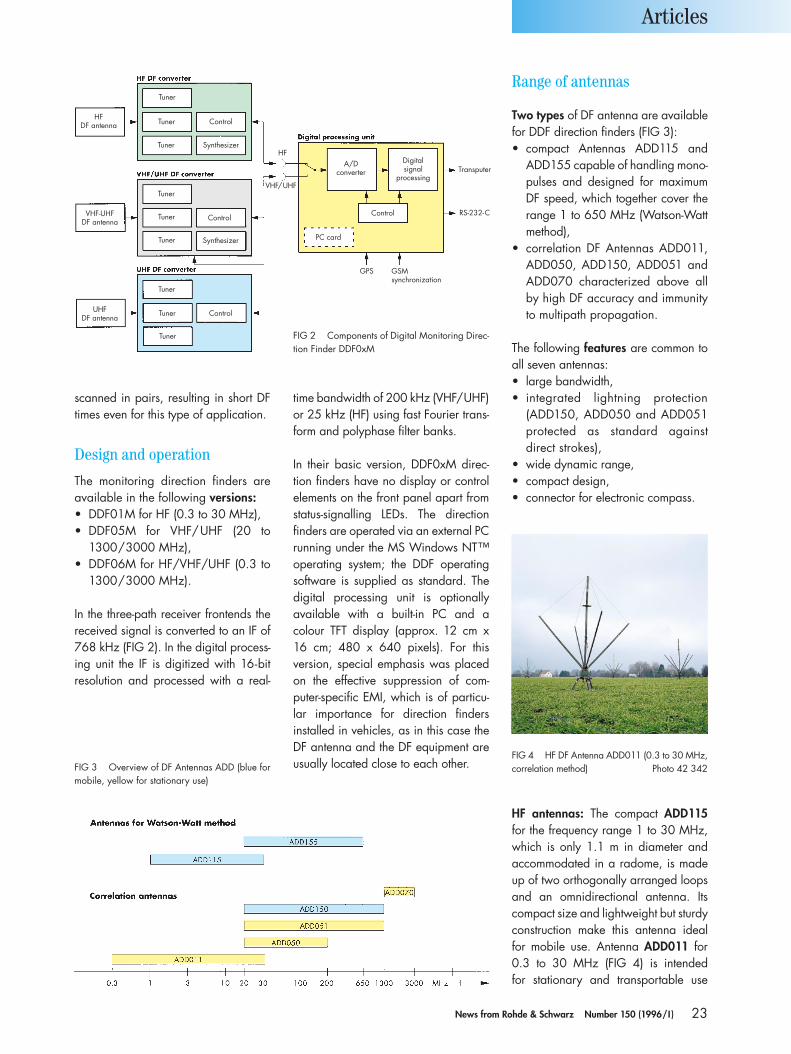
In the three-path receiver frontends thereceived signal is converted to an IF of768 kHz (FIG 2). In the digital process-ing unit the IF is digitized with 16-bitresolution and processed with a real-
time bandwidth of 200 kHz (VHF/UHF)or 25 kHz (HF) using fast Fourier trans-form and polyphase filter banks.
In their basic version, DDF0xM direc-tion finders have no display or controlelements on the front panel apart fromstatus-signalling LEDs. The directionfinders are operated via an external PCrunning under the MS Windows NT™operating system; the DDF operatingsoftware is supplied as standard. Thedigital processing unit is optionallyavailable with a built-in PC and acolour TFT display (approx. 12 cm x16 cm; 480 x 640 pixels). For this version, special emphasis was placedon the effective suppression of com-puter-specific EMI, which is of particu-lar importance for direction finders installed in vehicles, as in this case theDF antenna and the DF equipment areusually located close to each other.
HF antennas: The compact ADD115for the frequency range 1 to 30 MHz,which is only 1.1 m in diameter and accommodated in a radome, is madeup of two orthogonally arranged loopsand an omnidirectional antenna. Itscompact size and lightweight but sturdyconstruction make this antenna idealfor mobile use. Antenna ADD011 for0.3 to 30 MHz (FIG 4) is intended for stationary and transportable use
Articles
FIG 3 Overview of DF Antennas ADD (blue formobile, yellow for stationary use)
FIG 4 HF DF Antenna ADD011 (0.3 to 30 MHz,correlation method) Photo 42 342
HFDF antenna
Tuner
Tuner
Tuner
Control
Control
Tuner
Synthesizer
VHF-UHFDF antenna
Tuner
Tuner Synthesizer
UHFDF antenna
Tuner
Tuner
Tuner
Control
VHF/UHF
HFA/D
converter
Digitalsignal
processing
Control
PC card
GPS GSMsynchronization
Transputer
RS-232-C
FIG 2 Components of Digital Monitoring Direc-tion Finder DDF0xM
Range of antennas
Two types of DF antenna are availablefor DDF direction finders (FIG 3):• compact Antennas ADD115 and
ADD155 capable of handling mono-pulses and designed for maximumDF speed, which together cover therange 1 to 650 MHz (Watson-Wattmethod),
• correlation DF Antennas ADD011,ADD050, ADD150, ADD051 andADD070 characterized above all by high DF accuracy and immunityto multipath propagation.
The following features are common toall seven antennas:• large bandwidth,• integrated lightning protection
(ADD150, ADD050 and ADD051protected as standard against direct strokes),
• wide dynamic range,• compact design,• connector for electronic compass.
24 News from Rohde & Schwarz Number 150 (1996/I )
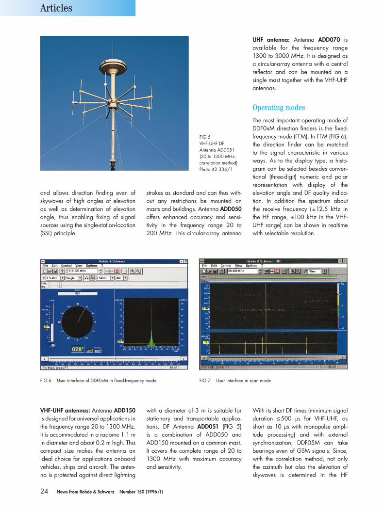
and allows direction finding even ofskywaves of high angles of elevation as well as determination of elevationangle, thus enabling fixing of signalsources using the single-station-location(SSL) principle.
strokes as standard and can thus with-out any restrictions be mounted onmasts and buildings. Antenna ADD050offers enhanced accuracy and sensi-tivity in the frequency range 20 to 200 MHz. This circular-array antenna
UHF antenna: Antenna ADD070 isavailable for the frequency range 1300 to 3000 MHz. It is designed as a circular-array antenna with a centralreflector and can be mounted on a single mast together with the VHF-UHFantennas.
Operating modes
The most important operating mode ofDDF0xM direction finders is the fixed-frequency mode (FFM). In FFM (FIG 6),the direction finder can be matched to the signal characteristic in variousways. As to the display type, a histo-gram can be selected besides conven-tional (three-digit) numeric and polarrepresentation with display of the elevation angle and DF quality indica-tion. In addition the spectrum about the receive frequency (±12.5 kHz inthe HF range, ±100 kHz in the VHF-UHF range) can be shown in realtimewith selectable resolution.
Articles
VHF-UHF antennas: Antenna ADD150is designed for universal applications inthe frequency range 20 to 1300 MHz.It is accommodated in a radome 1.1 min diameter and about 0.2 m high. Thiscompact size makes the antenna anideal choice for applications onboardvehicles, ships and aircraft. The anten-na is protected against direct lightning
with a diameter of 3 m is suitable forstationary and transportable applica-tions. DF Antenna ADD051 (FIG 5) is a combination of ADD050 andADD150 mounted on a common mast.It covers the complete range of 20 to1300 MHz with maximum accuracyand sensitivity.
With its short DF times (minimum signalduration ≤ 500 µs for VHF-UHF, as short as 10 µs with monopulse ampli-tude processing) and with external synchronization, DDF05M can takebearings even of GSM signals. Since,with the correlation method, not onlythe azimuth but also the elevation ofskywaves is determined in the HF
FIG 5VHF-UHF DF Antenna ADD051(20 to 1300 MHz,correlation method)Photo 42 334/1
FIG 6 User interface of DDF0xM in fixed-frequency mode FIG 7 User interface in scan mode
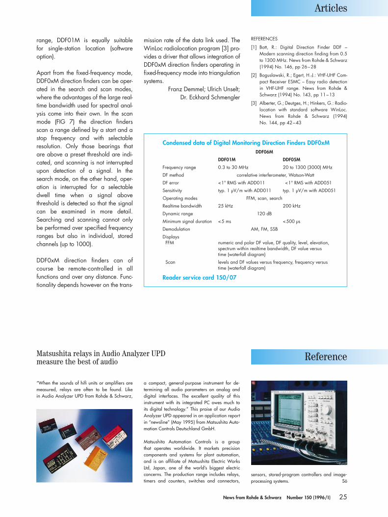
25News from Rohde & Schwarz Number 150 (1996/I )
range, DDF01M is equally suitable for single-station location (software option).
Apart from the fixed-frequency mode,DDF0xM direction finders can be oper-ated in the search and scan modes,where the advantages of the large real-time bandwidth used for spectral anal-ysis come into their own. In the scanmode (FIG 7) the direction finders scan a range defined by a start and astop frequency and with selectable resolution. Only those bearings that are above a preset threshold are indi-cated, and scanning is not interruptedupon detection of a signal. In thesearch mode, on the other hand, oper-ation is interrupted for a selectabledwell time when a signal above threshold is detected so that the signalcan be examined in more detail.Searching and scanning cannot onlybe performed over specified frequencyranges but also in individual, storedchannels (up to 1000).
DDF0xM direction finders can ofcourse be remote-controlled in all functions and over any distance. Func-tionality depends however on the trans-
mission rate of the data link used. TheWinLoc radiolocation program [3] pro-vides a driver that allows integration ofDDF0xM direction finders operating infixed-frequency mode into triangulationsystems.
Franz Demmel; Ulrich Unselt;Dr. Eckhard Schmengler
Articles
Condensed data of Digital Monitoring Direction Finders DDF0xMDDF06M
DDF01M DDF05M
Frequency range 0.3 to 30 MHz 20 to 1300 (3000) MHz
DF method correlative interferometer, Watson-Watt
DF error <1° RMS with ADD011 <1° RMS with ADD051
Sensitivity typ. 1 µV/m with ADD011 typ. 1 µV/m with ADD051
Operating modes FFM, scan, search
Realtime bandwidth 25 kHz 200 kHz
Dynamic range 120 dB
Minimum signal duration <5 ms <500 µs
Demodulation AM, FM, SSB
DisplaysFFM numeric and polar DF value, DF quality, level, elevation,
spectrum within realtime bandwidth, DF value versus time (waterfall diagram)
Scan levels and DF values versus frequency, frequency versus time (waterfall diagram)
Reader service card 150/07
REFERENCES
[1] Bott, R.: Digital Direction Finder DDF – Modern scanning direction finding from 0.5to 1300 MHz. News from Rohde & Schwarz(1994) No. 146, pp 26–28
[2] Boguslawski, R.; Egert, H.-J.: VHF-UHF Com-pact Receiver ESMC – Easy radio detection in VHF-UHF range. News from Rohde &Schwarz (1994) No. 143, pp 11–13
[3] Alberter, G.; Deutges, H.; Hinkers, G.: Radio-location with standard software WinLoc.News from Rohde & Schwarz (1994) No. 144, pp 42–43
Matsushita relays in Audio Analyzer UPDmeasure the best of audio Reference
“When the sounds of hifi units or amplifiers aremeasured, relays are often to be found. Like in Audio Analyzer UPD from Rohde & Schwarz,
a compact, general-purpose instrument for de-termining all audio parameters on analog anddigital interfaces. The excellent quality of this instrument with its integrated PC owes much to its digital technology.” This praise of our AudioAnalyzer UPD appeared in an application reportin “newsline” (May 1995) from Matsushita Auto-mation Controls Deutschland GmbH.
Matsushita Automation Controls is a group that operates worldwide. It markets precisioncomponents and systems for plant automation,and is an affiliate of Matsushita Electric WorksLtd, Japan, one of the world’s biggest electric concerns. The production range includes relays,timers and counters, switches and connectors,
sensors, stored-program controllers and image-processing systems. Sö

26 News from Rohde & Schwarz Number 150 (1996/I )
The new solid-state UHF TV transmittersof the NH500 series (FIG 1) presentedby Rohde & Schwarz at the TV Sympo-sium 95 in Montreux [1] operate, likesolid-state VHF Transmitters NM..5 [2],with Exciter SD200. This exciter withall-electronic tuning is designed for PAL,PALplus, NTSC or SECAM colour-tele-vision transmission as well as for dual-sound and stereo operation (IRT or NICAM). It directly drives the amplifiermodules for vision and sound (FIG 2)without the use of preamplifiers. Veryhigh transmission reliability is guaran-teed by the multiple redundancy of allRF power stages and power supplies
(many identical plug-in modules), evenfor operation with only a single trans-mitter.
The transmitter is nicknamed “ecoTV”as it consumes little power, requires littlespace and is low on logistics due toidentical vision and sound amplifiers.This means savings in operating costsand also in infrastructure. Solid-stateTransmitters NH500 have the followingmain features:• clearly arranged, modular configu-
ration,• power stages 5/ 7.5/10/15/20/
30 kW,• no signal degradation on removal of
power amplifiers,• protection facility in each amplifier
and power supply,
• patented R&S circuits for power con-trol, phase regulation and character-istic correction,
• exciter with precorrection of non-linear output-stage characteristics,regulated output power for visionand sound, regulated modulationsignals, synthesizer, precision offset,SAW vestigial-sideband filter, sync-pulse regeneration, dual-sound cod-ing and memory with four transmitterbasic setups including precorrection,
• split vision/sound amplification,• broadband amplifiers and power
couplers from 470 to 860 MHz,• bipolar high-power double transis-
tors,• low junction temperature of output-
stage transistors (<120°C/APL =50%),
• power supply with primary-switchedregulators for very high efficiency,
• microprocessor-based transmittercontrol unit for operation, monitor-ing and remote control,
• integrated automatic switchover foroption “passive exciter standby”,“active dual output stage”, “passivetransmitter standby“,
• very low heat dissipation thanks toforced-air cooling,
• high transmitter efficiency,
Articles
FIG 1 Solid-state UHF TV Transmitter NH500,the TV transmitter nicknamed ecoTV
Solid-state UHF TV Transmitter NH500
The new reference for TV transmitters: ecoTVAbout a year after the presentation of its solid-state TV transmitter for band III,Rohde & Schwarz is launching the solid-state TV Transmitter Family NH500 for band IV/V. Thanks to its modularity, transmitters with output power from 5 to30 kW can easily be implemented at a favourable price. Any standby conceptsas well as different standards are possible.

27News from Rohde & Schwarz Number 150 (1996/I )
• optional PAL, PALplus, NTSC or SECAM transmission,
• optional parallel or serial remoteinterface.
Mechanical designand operation
The interfaced modular design through-out allows virtually all possible trans-mitter configurations with regard to location and customer standby con-cepts. The transmitter is divided intotwo racks. The exciter rack accom-modates Exciter SD200, a transmitter control unit with display panel and remote interface, vision/sound diplexerand colour-subcarrier trap. The power-amplifier rack houses vision and soundamplifiers including power couplers,absorbers, power supply and har-monics filter. This rack can have up to ten plug-ins to provide vision power of 10 kW and sound power of 1.8 kW.For higher power, further racks withamplifier plug-ins are simply added tothe transmitter. A monitoring unit inte-grated in each rack signals operatingstates to the central control unit.
The amplifier and power-supply plug-ins are self-engaging (supply voltage,RF input, RF output, control and moni-toring bus) and can be replaced with-out having to interrupt operation. Afterreleasing a safety catch on the powersupply, the supply voltage and thus theRF power of the amplifier plug-in to beremoved are blocked – the plug-in canbe withdrawn with power switched off.The amplifier and power-supply plug-ins form an air duct. Thus, the amplifierrack merely requires an energy-saving,low-pressure cooling system.
The RF power of the vision-amplifierand sound-amplifier plug-ins in therack is combined by 0° couplers in triplate technology. The associated absorbers mounted on a heatsink areplaced direct in the cooling air stream.A diplexer feeds the vision and soundpower to the common antenna line. A colour-subcarrier trap for signals witha –4.43 and –8.84 MHz spacing from
the vision carrier prevents spuriousemission in the lower vestigial side-band. A built-in lightning arrester pro-tects the transmitter output from light-ning strokes at the antenna.
The micropocessor-based transmittercontrol unit handles the switch-on sequence, monitoring, display, LED in-dicators and remote control. The hard-ware for controlling “passive exciterstandby”, “active dual output stage” or“passive transmitter standby” is alreadyintegrated. To activate any of these, theRF switches with control and RF cablesand software are all that is required.
Exciter and 1.5-kW broadband amplifier
Exciter SD200 is used to produce standard RF vision and sound signals,to regenerate sync pulses and to ac-commodate precorrectors for linear,nonlinear and dynamic errors in theoutput stage. It is equipped for split orcombined amplification and designed
for dual-sound operation to IRT andNICAM. Setting of the exciter is fullyelectronic by software. All parameterssuch as basic setting of levelling or out-put-stage-specific precorrections are setfrom the display unit using the keypadand rollkey and are stored in non-volatile memory. For special conditions,such as operation at reduced power,for repairs or (n+1) standby, four configurations can be defined for level,linearity and group delay for example.The exciter can be set to a new con-figuration by command.
The vision and sound amplifiers are ofidentical design. The amplifier plug-in israted for 1.5 kW sync peak power andfor 900 W CW or peak sound power(dual-sound operation). It comprises aregulated predriver with integral input-power monitor, level and phase controlas well as a class-A driver stage for the drivers of class-AB output-stage tran-sistors. Eight output-stage modules de-coupled from each other and for powerof 220 W each are combined to obtainnominal power of 1.5 kW (vision) or900 W (sound). The total gain of theplug-in is approx. 53 dB. The powercoupler with integral directional cou-plers for monitoring is a printed circuitrequiring no adjustment. The RF ampli-fiers operate with standard transistors.At present, transistors from four well-known manufacturers are availableand can be used without having tomodify layout or adjustment.
Articles
FIG 2 Block diagram of 10-kW TV TransmitterNH510
Vision
Sound 1
Sound 2
ExciterSD 200
Div
ider
Div
ider
Div
ider
Com
bine
rC
ombi
ner
Com
bine
r
Div
ider
Com
bine
r
Harmonicsfilter
Dip
lexe
r
Col
our-
subc
arrie
r tra
p-4
,43
MH
zLig
htni
ng
prot
ectio
n
Vision 10 kW
Sound 1 kW
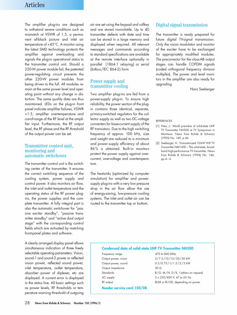
28 News from Rohde & Schwarz Number 150 (1996/I )
The amplifier plug-ins are designed to withstand severe conditions such asmismatch at VSWR of 1.5, a perma-nent all-black picture and inlet air temperature of +45°C. A monitor usingthe latest SMD technology protects theamplifier against overloading and signals the plug-in operational status tothe transmitter control unit. Should a220-W power module fail, the patentedpower-regulating circuit prevents theother 220-W power modules from being driven to the full. All modules re-main at the same power level and oper-ating point without any change in dis-tortion. The same quality data are thusmaintained. LEDs on the plug-in frontpanel indicate amplifier failures, VSWR>1.5, amplifier overtemperature andout-of-range of the RF level at the ampli-fier input. Furthermore, the RF outputlevel, the RF phase and the RF thresholdof the output power can be set.
Transmitter control unit,monitoring and automatic switchover
The transmitter control unit is the switch-ing center of the transmitter. It ensuresthe correct switching sequence of thecooling system, power supply and control power. It also monitors air flow,the inlet and outlet temperature and theoperating status of the RF power plug-ins, the power supplies and the com-plete transmitter. A fully integral part isalso the automatic switchover for “pas-sive exciter standby”, “passive trans-mitter standby” and “active dual outputstage” with the corresponding controlfields which are activated by matchingfront-panel plates and software.
A clearly arranged display panel allowssimultaneous indication of three freelyselectable operating parameters. Vision,sound-1 and sound-2 power or reflectedvision power, reflected sound power,inlet temperature, outlet temperature,absorber power of diplexer, etc are displayed. A current error is displayedin the status line. All basic settings suchas power levels, RF thresholds or tem-perature warning threshold of outgoing
air are set using the keypad and rollkeyand are stored nonvolatile. Up to 40transmitter defects with date and timecan be stored in a large memory anddisplayed when required. All relevantmessages and commands according to standard specifications are availableat the remote interface optionally inparallel (1864-1 relaying) or serial (bitbus/IEC 864-2) form.
Power supply and transmitter cooling
Two amplifier plug-ins are fed from apower-supply plug-in. To ensure high reliability, the power section of the plug-in contains three identical, separate,primary-switched regulators for the col-lector supply as well as two DC-voltageconverters for base-current supply of theRF transistors. Due to the high switchingfrequency of approx. 100 kHz, sizeand weight are reduced to a minimumand power-supply efficiency of about86% is obtained. Built-in monitors protect the power supply against over-current, overvoltage and overtempera-ture.
The heatsinks (optimized by computersimulation) for amplifier and power-supply plug-ins with a very low pressuredrop in the air flow allow the use of energy-saving, low-pressure coolingsystems. The inlet and outlet air can berouted to the transmitter top or bottom.
Articles
Condensed data of solid-state UHF TV Transmitter NH500Frequency range 470 to 860 MHz
Output power, vision 5/7.5/10/15/20/30 kW
Output power, sound 0.5/0.75/1/1.5/2/3 kW
Output impedance 50 Ω
Standards B/G, M/N, D/K, I (others on request)
AC supply 3 x 230/400 V, 47 to 63 Hz
RF output RL68 or RL100, depending on power
Reader service card 150/08
Digital signal transmission
The transmitter is ready prepared for future digital TV-signal transmission.Only the vision modulator and monitorof the exciter have to be exchanged for appropriately modified modules.The precorrector for the class-AB outputstages can handle COFDM signals(coded orthogonal frequency divisionmultiplex). The power and level moni-tors in the amplifier are also ready forupgrading.
Hans Seeberger
REFERENCES
[1] Nies, J.: World première of solid-state UHFTV Transmitter NH500 at TV Symposium inMontreux. News from Rohde & Schwarz(1995) No. 149, p 46
[2] Seeberger, H.: Transistorized 10-kW VHF TVTransmitter NM145E – The solid-state, broad-band high-performance TV transmitter. Newsfrom Rohde & Schwarz (1994) No. 146, pp 4 – 6

29News from Rohde & Schwarz Number 150 (1996/I )
Offering independence from infra-structure, providing a free transmissionmedium and given the big advancesmade in the development of securetransmission methods, shortwave has,in many cases, become a full-value information medium. The antenna hasa major influence on the transmissionquality. Any losses at this point of thetransmission link cannot be made up forat a later stage. That is why investmentsin antennas that are state-of-the-art al-ways pay off. Especially in the 100-Wclass it is very important not to wasteany of the effective radiated power by using low-cost antennas. As moderntransmission methods often operatewith a very large bandwidth, the antenna becomes more and more important for obtaining sufficient signal/noise ratio.
With the newly designed 150-W HF Dipole HX002A1 (FIG 1), Rohde &
Schwarz offers a 100-W class modelto go with the tried and tested An-tenna HX002 for 1 kW [1]. Its maincharacteristics are problem-free andcost-effective antenna installation, optimum radiation patterns and maxi-mum reliability.
The availability of the communicationlink is of major importance for anyshortwave user. Antennas with opti-mized performance data such as radiation patterns and gain make a vital contribution to fulfilling this require-ment. The radiation pattern has to bematched to the time- and frequency-dependent wave characteristics of theionosphere and to the orientation andlength of the transmission link: steeptakeoff angles and low frequencies arerequired for distances of up to somehundred kilometers whereas flat takeoffangles and higher frequencies areneeded for longer distances [2]. Short
and medium distances are especiallyproblematic as the low frequenciesused do not lend themselves to imple-menting a compact antenna. That iswhy rod and loop antennas have beenused up to now in many cases. Thedrawbacks of these antennas com-pared to HF Dipole HX002A1 are illus-trated in FIG 2. Despite the reasonablegain of the rod antenna, the null in thezenith of the radiation pattern preventshigh-angle radiation and the socalledskip zone is formed. Loop antennas,
on the other hand, may have radiationdirected upwards but efficiency andthus gain leave a lot to be desired withregard to the available antenna sizes.
Low-loss dipole antennas arranged horizontally at a sufficient heightabove ground yield the required radi-ation patterns and satisfactory gain.Compact antennas of high efficiencythat are small in relation to the oper-ating wavelength require low-loss tuning networks, however, to ensurematching with the feeder cable or with the transmitter output impedance.In systems with automatic link setup,for example, these networks have tobe tuned fully automatically in a frac-tion of a second. Broadband solutionsin the form of dipoles attenuated with resistors (implemented as loaded dipole, terminated folded dipole, in-verted-V, delta antenna, etc) do notyield acceptable gain even with
Articles
FIG 1 150-W HF DipoleHX002A1Photo 41 579
150-W HF Dipole HX002A1
The antenna for reliableshortwave linksEven in the age of optical-fiber and satellite links there is a need for other communication media. Experience gained from critical situations shows that evenfor very broadband and powerful satellite links bottlenecks in communication can occur. Just as in the past, shortwave can be recommended as an informationcarrier with many advantages and with it HF Dipole HX002A1 from Rohde &Schwarz.
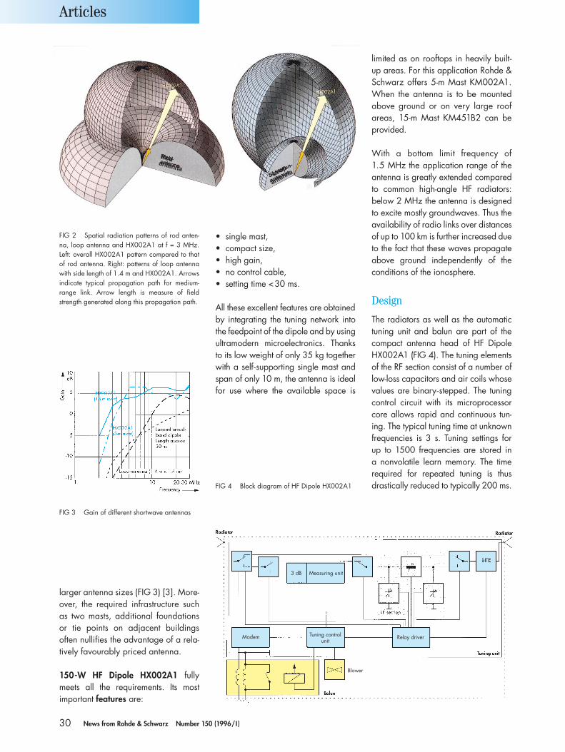
30 News from Rohde & Schwarz Number 150 (1996/I )
larger antenna sizes (FIG 3) [3]. More-over, the required infrastructure suchas two masts, additional foundationsor tie points on adjacent buildings often nullifies the advantage of a rela-tively favourably priced antenna.
150-W HF Dipole HX002A1 fullymeets all the requirements. Its most important features are:
• single mast,• compact size,• high gain,• no control cable,• setting time <30 ms.
All these excellent features are obtainedby integrating the tuning network intothe feedpoint of the dipole and by usingultramodern microelectronics. Thanksto its low weight of only 35 kg togetherwith a self-supporting single mast andspan of only 10 m, the antenna is idealfor use where the available space is
limited as on rooftops in heavily built-up areas. For this application Rohde &Schwarz offers 5-m Mast KM002A1.When the antenna is to be mountedabove ground or on very large roof areas, 15-m Mast KM451B2 can beprovided.
With a bottom limit frequency of 1.5 MHz the application range of theantenna is greatly extended comparedto common high-angle HF radiators: below 2 MHz the antenna is designedto excite mostly groundwaves. Thus theavailability of radio links over distancesof up to 100 km is further increased dueto the fact that these waves propagateabove ground independently of theconditions of the ionosphere.
Design
The radiators as well as the automatictuning unit and balun are part of thecompact antenna head of HF DipoleHX002A1 (FIG 4). The tuning elementsof the RF section consist of a number oflow-loss capacitors and air coils whosevalues are binary-stepped. The tuningcontrol circuit with its microprocessorcore allows rapid and continuous tun-ing. The typical tuning time at unknownfrequencies is 3 s. Tuning settings for up to 1500 frequencies are stored in a nonvolatile learn memory. The timerequired for repeated tuning is thusdrastically reduced to typically 200 ms.
Articles
FIG 2 Spatial radiation patterns of rod anten-na, loop antenna and HX002A1 at f = 3 MHz.Left: overall HX002A1 pattern compared to thatof rod antenna. Right: patterns of loop antennawith side length of 1.4 m and HX002A1. Arrowsindicate typical propagation path for medium-range link. Arrow length is measure of fieldstrength generated along this propagation path.
FIG 3 Gain of different shortwave antennas
FIG 4 Block diagram of HF Dipole HX002A1
3 dB Measuring unit
Modem Tuning controlunit
Relay driver
Blower
Rodantenna
Loop
antenna
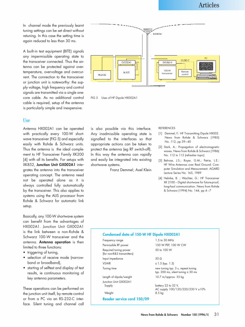
31News from Rohde & Schwarz Number 150 (1996/I )
In channel mode the previously learnttuning settings can be set direct withoutretuning. In this case the setting time isagain reduced to less than 30 ms.
A built-in test equipment (BITE) signalsany impermissible operating state tothe transceiver connected. Thus the an-tenna can be protected against over-temperature, overvoltage and overcur-rent. The connection to the transceiveror junction unit is noteworthy: the sup-ply voltage, high frequency and controlsignals are transmitted via a single one-core cable. As no additional controlcable is required, setup of the antennais particularly simple and inexpensive.
Use
Antenna HX002A1 can be operatedwith practically every 100-W short-wave transceiver (FIG 5) and especiallyeasily with Rohde & Schwarz units.Thus the antenna is the ideal comple-ment to HF Transceiver Family XK200[4] with all its benefits. For setups withXK852, Junction Unit GX002A1 inte-grates the antenna into the transceiveroperating concept. The antenna neednot be operated alone as it is always controlled fully automatically by the transceiver. This also applies tosystems using the ALIS processor fromRohde & Schwarz for automatic link setup.
Basically, any 100-W shortwave systemcan benefit from the advantages ofHX002A1. Junction Unit GX002A1 is the link between a non-Rohde &Schwarz 100-W transceiver and the antenna. Antenna operation is thenlimited to three functions:• triggering of tuning,• selection of receive mode (narrow-
band or broadband),• starting of selftest and display of test
results, ie continuous monitoring ofkey antenna parameters.
These operations can be performed onthe junction unit itself, by remote controlor from a PC via an RS-232-C inter-face. Silent tuning and channel call
is also possible via this interface. Any inadmissible operating state is signalled to the interfaces so that appropriate actions can be taken toprotect the antenna (eg RF switch-off). In this way the antenna can rapidly and easily be integrated into existingshortwave systems.
Franz Demmel; Axel Klein
Articles
FIG 5 Uses of HF Dipole HX002A1
Condensed data of 150-W HF Dipole HX002A1Frequency range 1.5 to 30 MHz
Permissible RF power 150 W PEP, 100 W CW
Required tuning power 50 to 100 W(for non-R&S transmitters)
Input impedance 50 Ω
VSWR ≤ 1.5 (typ. 1.3)
Tuning time new tuning typ. 3 s, repeat tuning typ. 200 ms, silent tuning ≤ 30 ms
Length of dipole/weight 10.7 m/approx. 35 kg
Junction Unit GX002A1Supply battery 22 to 32 V,
AC supply 100/120/220/230 V ±10%Weight 8.5 kg
Reader service card 150/09
100-Wtransceiver
Remotecontrol
ProcessorPC
REFERENCES
[1] Demmel; F.: HF Transmitting Dipole HX002.News from Rohde & Schwarz (1985) No. 112, pp 39–40
[2] Stark, A.: Propagation of electromagneticwaves. News from Rohde & Schwarz (1986)No. 112 to 115 (refresher topic)
[3] Belrose, J.S.; Royer, G.M.; Petrie, L.E.: HF Wire Antennas over Real Ground: Com-puter Simulation and Measurement. AGARDLecture Series No. 165, 1989
[4] Helmke, B. ; Wachter, G.: HF Transceiver XK 2100 – Digital shortwave for future-proof,long-haul communication. News from Rohde& Schwarz (1994) No. 144, pp 4 –7
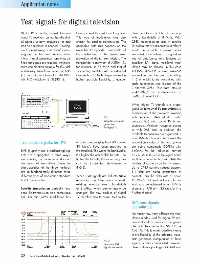
32 News from Rohde & Schwarz Number 150 (1996/I )
Digital TV is coming in fast. Conven-tional TV receivers cannot handle digi-tal signals, so new receivers or at leastadd-on equipment is needed. Develop-ment is in full swing at all manufacturersengaged in this field. Among otherthings, signal generators supplying de-fined test signals are required. An instru-ment combination suitable for this taskis Arbitrary Waveform Generator ADS[1] and Signal Generator SMHU58with I/Q modulator [2; 3] (FIG 1).
Transmission paths for DVB
DVB (digital video broadcasting) sig-nals are propagated in three ways:via satellite, on cable networks andvia terrestrial transmitters. Since thecharacteristics of the three methodsare so fundamentally different, threedifferent types of modulation standardhad to be specified.
Satellite transmission basically func-tions like transmission on a microwavelink. For this, QPSK modulation has
of data rates ranging from 40 to over80 Mbit/s have been specified in the standard. The wider the bandwidth,the higher the achievable bit rate. Thehigher the bit rate, the more programscan be transmitted simultaneously (FIG 2).
When DVB signals are fed into cablenetworks, a problem is encountered:existing networks have a bandwidth of 8 MHz, which cannot easily bechanged. The new medium of digitalTV therefore has to adapt itself to the
been successfully used for a long time.This type of modulation was also chosen for satellite transmission. The attainable data rate depends on theavailable transponder bandwidth ofthe satellite and on the desired errorprotection of digital transmission. Thetransponder bandwidth of ASTRA 1D,for instance, is 33 MHz and that of succeeding satellites will be extendedto more than 50 MHz. To guarantee thehighest possible flexibility, a number
given conditions, ie it has to managewith a bandwidth of 8 MHz. WithQPSK modulation as used in satelliteTV, a data rate of not more than 8 Mbit/swould be possible. However, sincetransmission on cables is as good asfree of disturbance and features an excellent S/N ratio, multi-level mod-ulation may be chosen. In this case 16QAM, 32QAM or even 64QAMmodulation can be used, permitting 4, 5 or 6 bits to be transmitted witheach modulation step instead of the 2 bits with QPSK. Thus data rates up to 42 Mbit/s can be obtained in an 8-MHz channel (FIG 3).
When digital TV signals are propa-gated via terrestrial TV transmitters, acombination of the problems involvedwith terrestrial DAB (digital audiobroadcasting) and cable TV is en-countered. Multipath reception occursas with DAB and, in addition, the available frequencies are organized in7- or 8-MHz channels. At present themodulation modes of the two systemsare being combined: COFDM with 64QAM for the individual carriers (FIG 4). As in this case the signal band-width may be wider than with DAB, thenumber of carriers can be increased.Up to 6785 carriers spaced approx.1.1 kHz are being considered atpresent. Thus the data rate of about 42 Mbit/s obtained in the cable net-work can be achieved in an 8-MHzchannel or 7/8 of it (35 Mbit/s) in a 7-MHz channel.
Different signals – one solution
No matter how very different the mod-ulation modes used for digital TV are,practically all of them can be gener-ated with the combination SMHU58 +ADS [4]. This is made possible thanksto the flexibility of the arbitrary wave-form generator. Computation of thesesignals is very complicated however.Here, software packages IQSIM-K and
Application notes
Test signals for digital television
FIG 1Setup for test-signalgeneration for digital TV
FIG 2Spectra of DVB signals via satellite
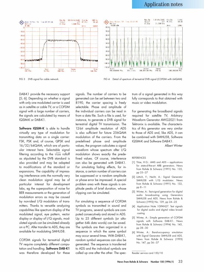
33News from Rohde & Schwarz Number 150 (1996/I )
DAB-K1 provide the necessary support[5; 6]. Depending on whether a signalwith only one modulated carrier is usedas in satellite or cable TV, or a COFDMsignal with a large number of carriers,the signals are calculated by means ofIQSIM-K or DAB-K1.
Software IQSIM-K is able to handle virtually any type of modulation fortransmitting data on a single carrier:FSK, PSK and, of course, QPSK and16/32/64QAM, which are of partic-ular interest here. Selectable signal filtering according to the √–––cos rolloff as stipulated by the DVB standard is also provided and may be adapted to modifications of the standard or expansions. The capability of impress-ing interference onto the normally veryclean modulation signal may be of particular interest for development labs, eg the superposition of noise forBER measurements or the generation ofmodulation errors as may be caused by non-ideal I/Q modulators of trans-mitters. Thanks to versatile analyzingcapabilities like spectrum display of themodulated signal, eye pattern, vectordisplay or display of I/Q signals, mod-ulated signals can be simulated alreadyon a PC. After transfer to ADS, they areavailable for modulating SMHU58.
COFDM signals for terrestrial digital TV require completely different compu-tation and handling. Software DAB-K1was therefore developed for these
signals. The number of carriers to begenerated can be set between two and8190, the carrier spacing is freely selectable. Phase and amplitude of the individual carriers can be read infrom a data file. Such a file is used, forinstance, to generate a DVB signal forterrestrial digital TV transmission. The12-bit amplitude resolution of ADS is also sufficient for future 256QAMmodulation of the carriers. From thepredefined phase and amplitude values, the program calculates a signalwaveform whose spectrum after I/Qmodulation shows exactly the prede-fined values. Of course, interferencecan also be generated with DAB-K1.For simulating fading effects, for in-stance, a certain number of carriers canbe suppressed or a random amplitudeor phase error be impressed. A specialproblem area with these signals is am-plitude peaks of brief duration, whoseclipping can be simulated.
For simulating a sequence of COFDMsymbols as transmitted in sound and TV programs, several symbols are com-puted consecutively and stored in ADS.Up to 25 different symbols (or alto-gether 64k data words) can be saved.The symbols are then organized in a sequence in which the same symbolmay occur several times. With DAB-K1,random symbol sequences can also begenerated. The sequence is transferredto ADS and the individual symbols arecalled up one after the other. The spec-
trum of a signal generated in this wayfully corresponds to that obtained withmusic or video modulation.
For generating the broadband signalsrequired for satellite TV, ArbitraryWaveform Generator AWG2021 fromTektronix is available. The characteris-tics of this generator are very similar to those of ADS and, like ADS, it can be combined with SMHU58, SoftwareIQSIM-K and Software DAB-K1.
Albert Winter
REFERENCES
[1] Titze, H.G.: AMS and ADS – applications for state-of-the-art ARB generators. Newsfrom Rohde & Schwarz (1991) No. 135, pp 25–27
[2] Lüttich, F.; Hecht, A.: Signal GeneratorSMHU58 with I /Q modulator. News from Rohde & Schwarz (1991) No. 132, pp 8 –11
[3] Winter, A.: Test-signal generation for digitalaudio broadcasting using GeneratorsSMHU58 and ADS. News from Rohde &Schwarz (1992) No. 139, pp 24 –25
[4] Application Note 1GPAN27: Test signalsfor digital audio and digital video broad-casting
[5] Winter, A.: Simple generation of COFDMsignals with Software DAB-K1. News from Rohde & Schwarz (1994) No. 145, pp 28 –30
[6] Winter, A.: Band-occupancy simulationwith Signal Generator SMHU58 and ADS.News from Rohde & Schwarz (1995) No. 147, pp 36 –37
Reader service card 150/10
Application notes
FIG 3 DVB signal for cable network FIG 4 Detail of spectrum of terrestrial DVB signal (COFDM with 64QAM)
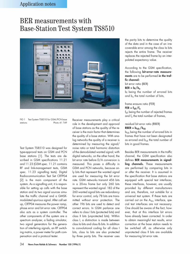
34 News from Rohde & Schwarz Number 150 (1996/I )
Test System TS8510 was designed fortype-approval tests on GSM and PCNbase stations [1]. The tests are de-scribed in GSM specifications 11.21and 11.23 (GSM spec. 11.21 containsRF and link-management tests, GSMspec. 11.23 signalling tests). DigitalRadiocommunication Test Set CRTP04[2] is the main component of thesystem. As a signalling unit, it is respon-sible for setting up calls with the basestation and its two signal sources simu-late the traffic channel and a GMSK-modulated spurious signal. After call set-up, CRTP04 measures the power ramp,phase error and bit error rate. CRTP04also acts as a system controller. The other components of the system are aspectrum analyzer, a fading simulator,two signal generators for the genera-tion of interfering signals, an RF switch-ing matrix, a power meter for path com-pensation and a protocol tester.
Receiver measurements play a criticalrole in the development and approvalof base stations as the quality of the re-ceiver is the main factor that determinesthe quality of a base station. With ana-log networks the quality of a receiver isdetermined by measuring the signal/noise ratio or total harmonic distortionof the demodulated wanted signal; withdigital networks, on the other hand, thebit error rate before D/A conversion ismeasured. This poses a difficulty inGSM and PCN networks, because on-ly bits that represent the wanted signalare used for measuring the bit errorrate. GSM networks transmit 456 bitsin a 20-ms frame but only 260 bits represent the wanted signal. 182 of the260 wanted signal bits use redundancyfor error control, only 78 bits are trans-mitted without error protection. The other 196 bits are used to detect andcorrect errors. In GSM parlance one refers to class I bits (protected bits) andclass II bits (unprotected bits). Withinclass I, a distinction is made betweenclass Ia bits and class Ib bits. In additionto convolutional coding for all class Ibits, class Ia bits are also protected by three parity bits. The receiver uses
the parity bits to determine the qualityof the data and in the case of an irre-coverable error among the class Ia bitsrejects the entire frame. The receiver replaces the rejected frame by an inter-polated expectancy value.
According to the GSM specification,the following bit-error-rate measure-ments are to be performed in the traf-fic channel:bit error ratio (BER)BER = bf/bo
bf being the number of errored bitsand bo the total number of bits,
frame erasure ratio (FER)FER = fbfi/fofbfi being the number of rejected framesand fo the total number of frames,
residual bit error ratio (RBER)RBER = bfok /bok
bfok being the number of errored bits inframes that have not been designatedas errored and bok the total number ofbits in good frames.
Besides BER measurements in the trafficchannel, the GSM specification alsodefines BER measurements in signal-ling channels. These measurements are performed by comparing bits in or after the receiver. It is assumed in the specification that base stations areequipped with special test interfaces;these interfaces, however, are usuallyprovided by different manufacturersand are, therefore, not suitable for auniversal test system. If these tests arecarried out on the Abis interface, spe-cial test interfaces are not necessary.One should be aware of the fact, how-ever, that at this interface bit errorshave already been corrected. In orderto obtain meaningful test results, errorcorrection at the base station needs tobe switched off, as otherwise only unprotected class II bits are availablefor measuring bit error rate.
Application notes
FIG 1 Test System TS8510 for GSM/PCN basestations Photo 41 749
BER measurements with Base-Station Test System TS8510
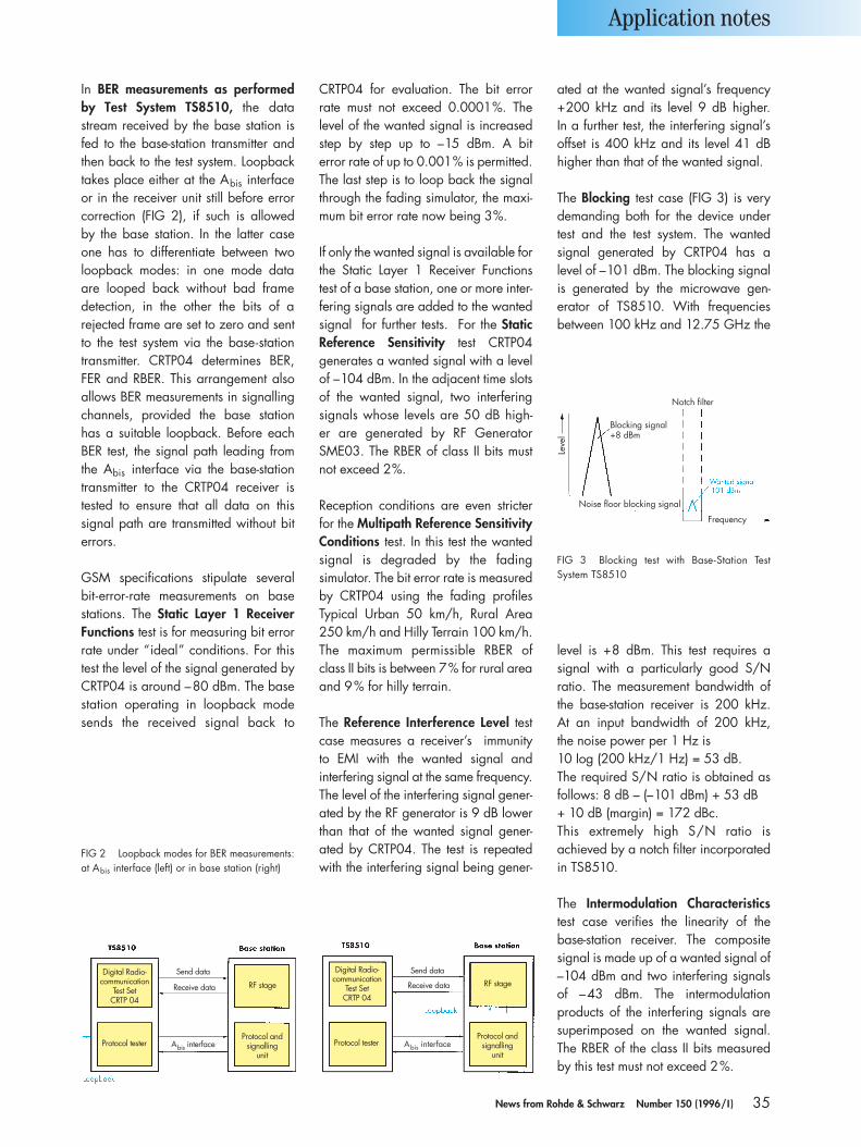
35News from Rohde & Schwarz Number 150 (1996/I )
In BER measurements as performedby Test System TS8510, the datastream received by the base station isfed to the base-station transmitter andthen back to the test system. Loopbacktakes place either at the Abis interfaceor in the receiver unit still before errorcorrection (FIG 2), if such is allowed by the base station. In the latter caseone has to differentiate between twoloopback modes: in one mode data are looped back without bad frame detection, in the other the bits of a rejected frame are set to zero and sentto the test system via the base-stationtransmitter. CRTP04 determines BER,FER and RBER. This arrangement alsoallows BER measurements in signallingchannels, provided the base station has a suitable loopback. Before eachBER test, the signal path leading fromthe Abis interface via the base-stationtransmitter to the CRTP04 receiver istested to ensure that all data on this signal path are transmitted without biterrors.
GSM specifications stipulate severalbit-error-rate measurements on base stations. The Static Layer 1 ReceiverFunctions test is for measuring bit errorrate under “ideal” conditions. For thistest the level of the signal generated byCRTP04 is around –80 dBm. The basestation operating in loopback modesends the received signal back to
CRTP04 for evaluation. The bit errorrate must not exceed 0.0001%. Thelevel of the wanted signal is increasedstep by step up to –15 dBm. A bit error rate of up to 0.001% is permitted.The last step is to loop back the signalthrough the fading simulator, the maxi-mum bit error rate now being 3%.
If only the wanted signal is available forthe Static Layer 1 Receiver Functionstest of a base station, one or more inter-fering signals are added to the wantedsignal for further tests. For the StaticReference Sensitivity test CRTP04 generates a wanted signal with a levelof –104 dBm. In the adjacent time slotsof the wanted signal, two interferingsignals whose levels are 50 dB high-er are generated by RF GeneratorSME03. The RBER of class II bits mustnot exceed 2%.
Reception conditions are even stricterfor the Multipath Reference SensitivityConditions test. In this test the wantedsignal is degraded by the fading simulator. The bit error rate is measuredby CRTP04 using the fading profilesTypical Urban 50 km/h, Rural Area250 km/h and Hilly Terrain 100 km/h.The maximum permissible RBER of class II bits is between 7% for rural areaand 9% for hilly terrain.
The Reference Interference Level testcase measures a receiver’s immunity to EMI with the wanted signal and interfering signal at the same frequency.The level of the interfering signal gener-ated by the RF generator is 9 dB lowerthan that of the wanted signal gener-ated by CRTP04. The test is repeatedwith the interfering signal being gener-
ated at the wanted signal’s frequency+200 kHz and its level 9 dB higher. In a further test, the interfering signal’soffset is 400 kHz and its level 41 dBhigher than that of the wanted signal.
The Blocking test case (FIG 3) is verydemanding both for the device undertest and the test system. The wanted signal generated by CRTP04 has a level of –101 dBm. The blocking signalis generated by the microwave gen-erator of TS8510. With frequenciesbetween 100 kHz and 12.75 GHz the
level is +8 dBm. This test requires a signal with a particularly good S/N ratio. The measurement bandwidth ofthe base-station receiver is 200 kHz. At an input bandwidth of 200 kHz, the noise power per 1 Hz is 10 Iog (200 kHz/1 Hz) = 53 dB. The required S/N ratio is obtained asfollows: 8 dB – (–101 dBm) + 53 dB + 10 dB (margin) = 172 dBc. This extremely high S/N ratio isachieved by a notch filter incorporatedin TS8510.
The Intermodulation Characteristicstest case verifies the linearity of thebase-station receiver. The compositesignal is made up of a wanted signal of–104 dBm and two interfering signalsof –43 dBm. The intermodulation products of the interfering signals aresuperimposed on the wanted signal.The RBER of the class II bits measuredby this test must not exceed 2%.
Application notes
FIG 2 Loopback modes for BER measurements:at Abis interface (left) or in base station (right)
FIG 3 Blocking test with Base-Station Test System TS8510
Digital Radio-communication
Test SetCRTP 04
Protocol tester
Send data
Receive data
Abis interface
RF stage
Protocol andsignalling
unitAbis interface
Digital Radio-communication
Test SetCRTP 04
Protocol tester
Send data
Receive data RF stage
Protocol andsignalling
unit
Leve
l
Frequency
Blocking signal+8 dBm
Notch filter
Noise floor blocking signal
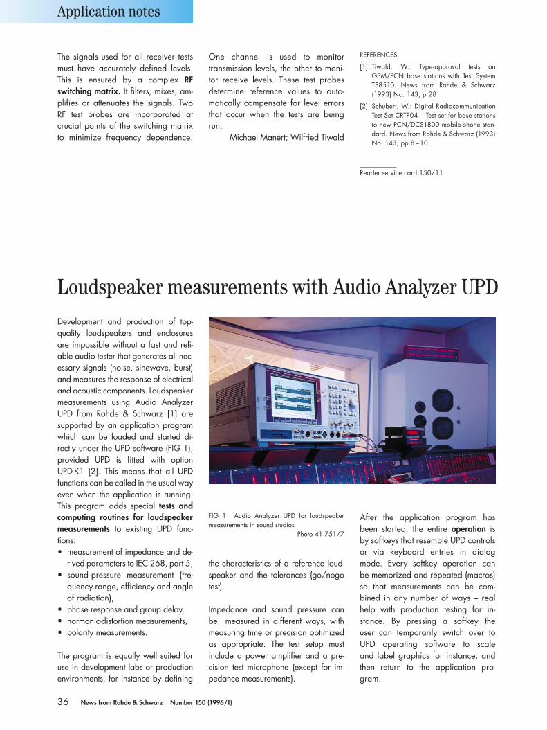
36 News from Rohde & Schwarz Number 150 (1996/I )
The signals used for all receiver testsmust have accurately defined levels.This is ensured by a complex RF switching matrix. It filters, mixes, am-plifies or attenuates the signals. TwoRF test probes are incorporated at crucial points of the switching matrixto minimize frequency dependence.
One channel is used to monitor transmission levels, the other to moni-tor receive levels. These test probesdetermine reference values to auto-matically compensate for level errorsthat occur when the tests are beingrun.
Michael Manert; Wilfried Tiwald
Application notes
Development and production of top-quality loudspeakers and enclosuresare impossible without a fast and reli-able audio tester that generates all nec-essary signals (noise, sinewave, burst)and measures the response of electricaland acoustic components. Loudspeakermeasurements using Audio AnalyzerUPD from Rohde & Schwarz [1] aresupported by an application programwhich can be loaded and started di-rectly under the UPD software (FIG 1),provided UPD is fitted with option UPD-K1 [2]. This means that all UPDfunctions can be called in the usual wayeven when the application is running.This program adds special tests andcomputing routines for loudspeakermeasurements to existing UPD func-tions:• measurement of impedance and de-
rived parameters to IEC 268, part 5,• sound-pressure measurement (fre-
quency range, efficiency and angleof radiation),
• phase response and group delay,• harmonic-distortion measurements,• polarity measurements.
The program is equally well suited foruse in development labs or productionenvironments, for instance by defining
the characteristics of a reference loud-speaker and the tolerances (go/nogotest).
Impedance and sound pressure can be measured in different ways, withmeasuring time or precision optimizedas appropriate. The test setup must include a power amplifier and a pre-cision test microphone (except for im-pedance measurements).
After the application program has been started, the entire operation is by softkeys that resemble UPD controlsor via keyboard entries in dialogmode. Every softkey operation can be memorized and repeated (macros)so that measurements can be com-bined in any number of ways – realhelp with production testing for in-stance. By pressing a softkey the user can temporarily switch over toUPD operating software to scale and label graphics for instance, andthen return to the application pro-gram.
FIG 1 Audio Analyzer UPD for loudspeakermeasurements in sound studios
Photo 41 751/7
Loudspeaker measurements with Audio Analyzer UPD
REFERENCES
[1] Tiwald, W.: Type-approval tests onGSM/PCN base stations with Test SystemTS8510. News from Rohde & Schwarz(1993) No. 143, p 28
[2] Schubert, W.: Digital RadiocommunicationTest Set CRTP04 – Test set for base stationsto new PCN/DCS1800 mobile-phone stan-dard. News from Rohde & Schwarz (1993)No. 143, pp 8 –10
Reader service card 150/11
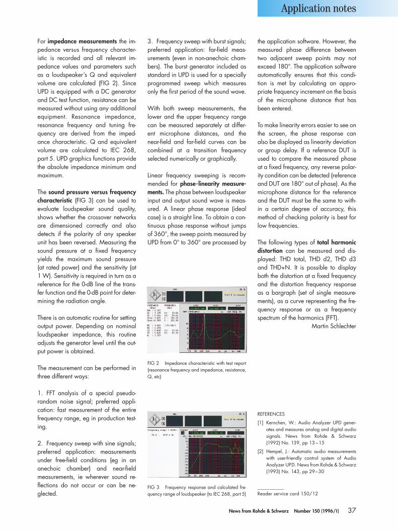
37News from Rohde & Schwarz Number 150 (1996/I )
For impedance measurements the im-pedance versus frequency character-istic is recorded and all relevant im-pedance values and parameters suchas a loudspeaker’s Q and equivalentvolume are calculated (FIG 2). SinceUPD is equipped with a DC generatorand DC test function, resistance can bemeasured without using any additionalequipment. Resonance impedance, resonance frequency and tuning fre-quency are derived from the imped-ance characteristic. Q and equivalentvolume are calculated to IEC 268, part 5. UPD graphics functions provide the absolute impedance minimum andmaximum.
The sound pressure versus frequencycharacteristic (FIG 3) can be used toevaluate loudspeaker sound quality,shows whether the crossover networksare dimensioned correctly and also detects if the polarity of any speakerunit has been reversed. Measuring thesound pressure at a fixed frequencyyields the maximum sound pressure (at rated power) and the sensitivity (at 1 W). Sensitivity is required in turn as areference for the 0-dB line of the trans-fer function and the 0-dB point for deter-mining the radiation angle.
There is an automatic routine for settingoutput power. Depending on nominalloudspeaker impedance, this routineadjusts the generator level until the out-put power is obtained.
The measurement can be performed inthree different ways:
1. FFT analysis of a special pseudo-random noise signal; preferred appli-cation: fast measurement of the entirefrequency range, eg in production test-ing.
2. Frequency sweep with sine signals;preferred application: measurementsunder free-field conditions (eg in an anechoic chamber) and near-fieldmeasurements, ie wherever sound re-flections do not occur or can be ne-glected.
3. Frequency sweep with burst signals;preferred application: far-field meas-urements (even in non-anechoic cham-bers). The burst generator included asstandard in UPD is used for a speciallyprogrammed sweep which measuresonly the first period of the sound wave.
With both sweep measurements, thelower and the upper frequency rangecan be measured separately at differ-ent microphone distances, and thenear-field and far-field curves can becombined at a transition frequency selected numerically or graphically.
Linear frequency sweeping is recom-mended for phase-linearity measure-ments. The phase between loudspeakerinput and output sound wave is meas-ured. A linear phase response (idealcase) is a straight line. To obtain a con-tinuous phase response without jumpsof 360°, the sweep points measured byUPD from 0° to 360° are processed by
the application software. However, themeasured phase difference betweentwo adjacent sweep points may not exceed 180°. The application softwareautomatically ensures that this condi-tion is met by calculating an appro-priate frequency increment on the basisof the microphone distance that hasbeen entered.
To make linearity errors easier to see onthe screen, the phase response can also be displayed as linearity deviationor group delay. If a reference DUT isused to compare the measured phaseat a fixed frequency, any reverse polar-ity condition can be detected (referenceand DUT are 180° out of phase). As themicrophone distance for the referenceand the DUT must be the same to with-in a certain degree of accuracy, thismethod of checking polarity is best forlow frequencies.
The following types of total harmonicdistortion can be measured and dis-played: THD total, THD d2, THD d3and THD+N. It is possible to displayboth the distortion at a fixed frequencyand the distortion frequency responseas a bargraph (set of single measure-ments), as a curve representing the fre-quency response or as a frequencyspectrum of the harmonics (FFT).
Martin Schlechter
Application notes
FIG 2 Impedance characteristic with test report(resonance frequency and impedance, resistance,Q, etc)
FIG 3 Frequency response and calculated fre-quency range of loudspeaker (to IEC 268, part 5)
REFERENCES
[1] Kernchen, W.: Audio Analyzer UPD gener-ates and measures analog and digital audiosignals. News from Rohde & Schwarz(1992) No. 139, pp 13 –15
[2] Hempel, J.: Automatic audio measurementswith user-friendly control system of Audio Analyzer UPD. News from Rohde & Schwarz(1993) No. 143, pp 29–30
Reader service card 150/12
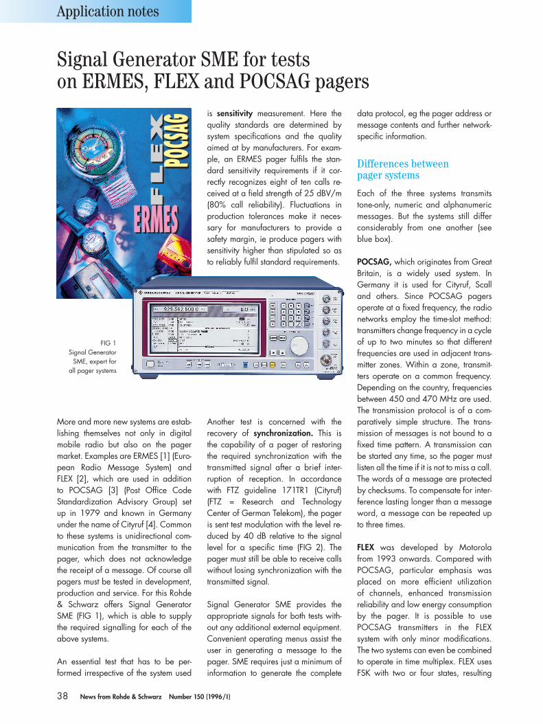
38 News from Rohde & Schwarz Number 150 (1996/I )
More and more new systems are estab-lishing themselves not only in digitalmobile radio but also on the pager market. Examples are ERMES [1] (Euro-pean Radio Message System) and FLEX [2], which are used in addition to POCSAG [3] (Post Office Code Standardization Advisory Group) setup in 1979 and known in Germanyunder the name of Cityruf [4]. Commonto these systems is unidirectional com-munication from the transmitter to thepager, which does not acknowledgethe receipt of a message. Of course allpagers must be tested in development,production and service. For this Rohde& Schwarz offers Signal GeneratorSME (FIG 1), which is able to supplythe required signalling for each of theabove systems.
An essential test that has to be per-formed irrespective of the system used
Another test is concerned with the recovery of synchronization. This is the capability of a pager of restoringthe required synchronization with thetransmitted signal after a brief inter-ruption of reception. In accordancewith FTZ guideline 171TR1 (Cityruf) (FTZ = Research and Technology Center of German Telekom), the pageris sent test modulation with the level re-duced by 40 dB relative to the signallevel for a specific time (FIG 2). Thepager must still be able to receive callswithout losing synchronization with thetransmitted signal.
Signal Generator SME provides the appropriate signals for both tests with-out any additional external equipment.Convenient operating menus assist theuser in generating a message to thepager. SME requires just a minimum ofinformation to generate the complete
data protocol, eg the pager address ormessage contents and further network-specific information.
Differences between pager systems
Each of the three systems transmitstone-only, numeric and alphanumericmessages. But the systems still differconsiderably from one another (seeblue box).
POCSAG, which originates from GreatBritain, is a widely used system. In Germany it is used for Cityruf, Scalland others. Since POCSAG pagers operate at a fixed frequency, the radionetworks employ the time-slot method:transmitters change frequency in a cycleof up to two minutes so that different frequencies are used in adjacent trans-mitter zones. Within a zone, transmit-ters operate on a common frequency.Depending on the country, frequenciesbetween 450 and 470 MHz are used.The transmission protocol is of a com-paratively simple structure. The trans-mission of messages is not bound to afixed time pattern. A transmission canbe started any time, so the pager mustlisten all the time if it is not to miss a call.The words of a message are protectedby checksums. To compensate for inter-ference lasting longer than a messageword, a message can be repeated upto three times.
FLEX was developed by Motorola from 1993 onwards. Compared withPOCSAG, particular emphasis wasplaced on more efficient utilization of channels, enhanced transmission reliability and low energy consumptionby the pager. It is possible to use POCSAG transmitters in the FLEXsystem with only minor modifications.The two systems can even be combinedto operate in time multiplex. FLEX usesFSK with two or four states, resulting
Application notes
is sensitivity measurement. Here thequality standards are determined bysystem specifications and the qualityaimed at by manufacturers. For exam-ple, an ERMES pager fulfils the stan-dard sensitivity requirements if it cor-rectly recognizes eight of ten calls re-ceived at a field strength of 25 dBV/m(80% call reliability). Fluctuations inproduction tolerances make it neces-sary for manufacturers to provide asafety margin, ie produce pagers withsensitivity higher than stipulated so asto reliably fulfil standard requirements.
FIG 1Signal Generator
SME, expert for all pager systems
Signal Generator SME for testson ERMES, FLEX and POCSAG pagers
FLEX
FLEX
POCSAG
POCSAG
ERMESERMES
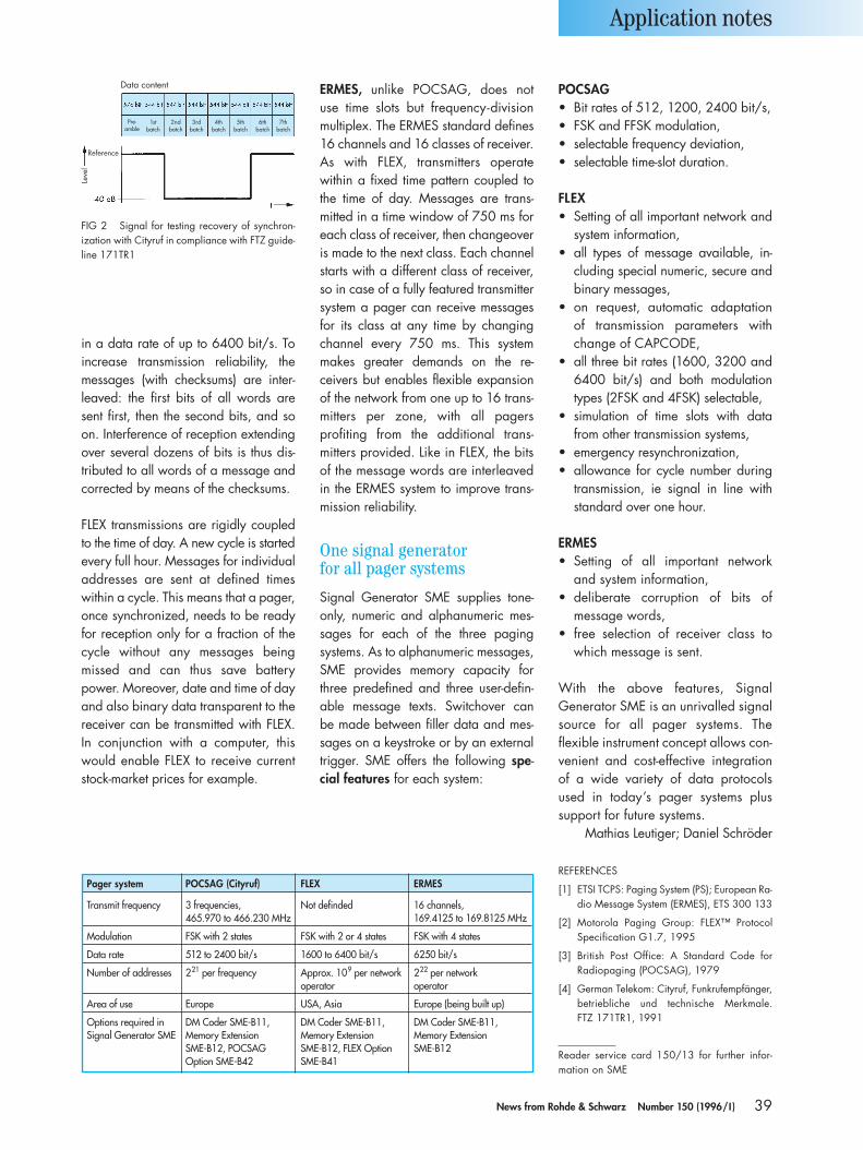
Pager system POCSAG (Cityruf) FLEX ERMES
Transmit frequency 3 frequencies, Not definded 16 channels,465.970 to 466.230 MHz 169.4125 to 169.8125 MHz
Modulation FSK with 2 states FSK with 2 or 4 states FSK with 4 states
Data rate 512 to 2400 bit/s 1600 to 6400 bit/s 6250 bit/s
Number of addresses 221 per frequency Approx. 109 per network 222 per network operator operator
Area of use Europe USA, Asia Europe (being built up)
Options required in DM Coder SME-B11, DM Coder SME-B11, DM Coder SME-B11,Signal Generator SME Memory Extension Memory Extension Memory Extension
SME-B12, POCSAG SME-B12, FLEX Option SME-B12Option SME-B42 SME-B41
39News from Rohde & Schwarz Number 150 (1996/I )
in a data rate of up to 6400 bit/s. Toincrease transmission reliability, themessages (with checksums) are inter-leaved: the first bits of all words aresent first, then the second bits, and soon. Interference of reception extendingover several dozens of bits is thus dis-tributed to all words of a message andcorrected by means of the checksums.
FLEX transmissions are rigidly coupledto the time of day. A new cycle is startedevery full hour. Messages for individualaddresses are sent at defined timeswithin a cycle. This means that a pager,once synchronized, needs to be readyfor reception only for a fraction of thecycle without any messages beingmissed and can thus save battery power. Moreover, date and time of dayand also binary data transparent to thereceiver can be transmitted with FLEX.In conjunction with a computer, thiswould enable FLEX to receive currentstock-market prices for example.
ERMES, unlike POCSAG, does not use time slots but frequency-divisionmultiplex. The ERMES standard defines16 channels and 16 classes of receiver.As with FLEX, transmitters operate within a fixed time pattern coupled tothe time of day. Messages are trans-mitted in a time window of 750 ms foreach class of receiver, then changeoveris made to the next class. Each channelstarts with a different class of receiver,so in case of a fully featured transmittersystem a pager can receive messagesfor its class at any time by changingchannel every 750 ms. This systemmakes greater demands on the re-ceivers but enables flexible expansionof the network from one up to 16 trans-mitters per zone, with all pagers profiting from the additional trans-mitters provided. Like in FLEX, the bits of the message words are interleavedin the ERMES system to improve trans-mission reliability.
One signal generatorfor all pager systems
Signal Generator SME supplies tone-only, numeric and alphanumeric mes-sages for each of the three pagingsystems. As to alphanumeric messages,SME provides memory capacity forthree predefined and three user-defin-able message texts. Switchover can be made between filler data and mes-sages on a keystroke or by an externaltrigger. SME offers the following spe-cial features for each system:
POCSAG• Bit rates of 512, 1200, 2400 bit/s,• FSK and FFSK modulation,• selectable frequency deviation,• selectable time-slot duration.
FLEX• Setting of all important network and
system information,• all types of message available, in-
cluding special numeric, secure andbinary messages,
• on request, automatic adaptation of transmission parameters withchange of CAPCODE,
• all three bit rates (1600, 3200 and6400 bit/s) and both modulationtypes (2FSK and 4FSK) selectable,
• simulation of time slots with datafrom other transmission systems,
• emergency resynchronization,• allowance for cycle number during
transmission, ie signal in line withstandard over one hour.
ERMES• Setting of all important network
and system information,• deliberate corruption of bits of
message words,• free selection of receiver class to
which message is sent.
With the above features, Signal Generator SME is an unrivalled signalsource for all pager systems. The flexible instrument concept allows con-venient and cost-effective integrationof a wide variety of data protocolsused in today’s pager systems plussupport for future systems.
Mathias Leutiger; Daniel Schröder
REFERENCES
[1] ETSI TCPS: Paging System (PS); European Ra-dio Message System (ERMES), ETS 300 133
[2] Motorola Paging Group: FLEX™ ProtocolSpecification G1.7, 1995
[3] British Post Office: A Standard Code for Radiopaging (POCSAG), 1979
[4] German Telekom: Cityruf, Funkrufempfänger,betriebliche und technische Merkmale. FTZ 171TR1, 1991
Reader service card 150/13 for further infor-mation on SME
Application notes
FIG 2 Signal for testing recovery of synchron-ization with Cityruf in compliance with FTZ guide-line 171TR1
Pre-amble
1stbatch
2ndbatch
3rdbatch
4thbatch
5thbatch
6thbatch
7thbatch
Data content
Reference
Leve
l
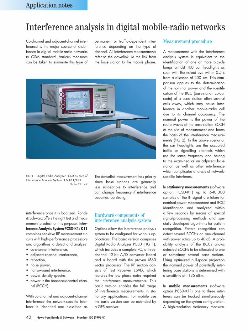
40 News from Rohde & Schwarz Number 150 (1996/I )
Co-channel and adjacent-channel inter-ference is the major source of distur-bance in digital mobile-radio networksto GSM standard. Various measurescan be taken to eliminate this type of
interference once it is localized. Rohde& Schwarz offers the right test and meas-urement product for this purpose. Inter-ference Analysis System PCSD-K1/K11combines sensitive RF measurement cir-cuits with high-performance processorsand algorithms to detect and analyze• co-channel interference,• adjacent-channel interference,• reflection,• noise power,• narrowband interference,• power density spectra,• power in the broadcast control chan-
nel (BCCH).
With co-channel and adjacent-channelinterference the network-specific inter-ferer is identified and classified as
The downlink measurement has prioritysince base stations are generally less susceptible to interference and can change frequency if interferencebecomes too strong.
Hardware components ofinterference analysis system
Options allow the interference analysissystem to be configured for various ap-plications. The basic version comprisesDigital Radio Analyzer PCSD (FIG 1),which includes a complete PC, a three-channel 12-bit A/D converter boardand a board with the proven i860 vector processor. The RF section con-sists of Test Receiver ESVD, which features the low phase noise requiredfor interference measurements. This basic version enables the full range of interference measurements in sta-tionary applications. For mobile use the basic version can be extended by a GPS receiver.
permanent or traffic-dependent inter-ference depending on the type of channel. All interference measurementsrefer to the downlink, ie the link fromthe base station to the mobile phone.
Measurement procedure
A measurement with the interferenceanalysis system is equivalent to theidentification of one or more bicyclelamps amidst 100 car headlights asseen with the naked eye within 0.5 sfrom a distance of 200 km. This com-parison applies to the determination of the nominal power and the identifi-cation of the BCC (base-station colourcode) of a base station often severalcells away, which may cause inter-ference in another mobile-radio celldue to its channel occupancy. The nominal power is the power of the radio waves of the base-station BCCHat the site of measurement and formsthe basis of the interference measure-ments (FIG 2). In the above scenario,the car headlights are the occupied traffic or signalling channels which use the same frequency and belong to the examined or an adjacent basestation as well as other interferencewhich complicates analysis of network-specific interferers.
In stationary measurements (softwareoption PCSD-K1) up to 640,000 samples of the IF signal are taken fornominal-power measurement and BCCidentification and analyzed within a few seconds by means of special signal-processing methods and spe-cially developed algorithms for patternrecognition. Pattern recognition can detect several BCCHs on one channelwith power ratios up to 40 dB. A prob-ability analysis of the BCCs allows detected BCCHs to be allocated to oneor sometimes several base stations. Using optimized null-space projectionthe nominal power of potentially inter-fering base stations is determined witha sensitivity of –135 dBm.
In mobile measurements (software option PCSD-K11) one to three inter-ferers can be tracked simultaneouslydepending on the system configuration.A high-resolution stationary measure-
Application notes
FIG 1 Digital Radio Analyzer PCSD as core ofInterference Analysis System PCSD-K1/K11
Photo 42 147
Interference analysis in digital mobile-radio networks
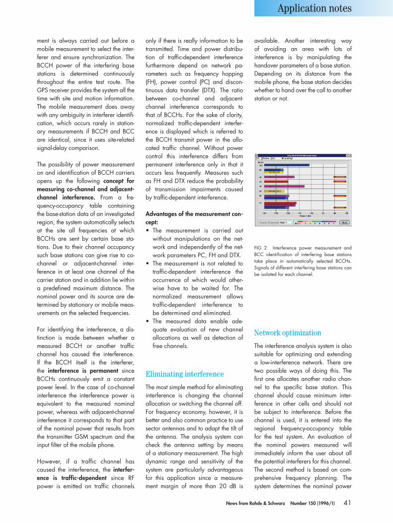
41News from Rohde & Schwarz Number 150 (1996/I )
ment is always carried out before a mobile measurement to select the inter-ferer and ensure synchronization. TheBCCH power of the interfering basestations is determined continuouslythroughout the entire test route. TheGPS receiver provides the system all thetime with site and motion information.The mobile measurement does awaywith any ambiguity in interferer identifi-cation, which occurs rarely in station-ary measurements if BCCH and BCCare identical, since it uses site-relatedsignal-delay comparison.
The possibility of power measurementon and identification of BCCH carriersopens up the following concept formeasuring co-channel and adjacent-channel interference. From a fre-quency-occupancy table containing the base-station data of an investigatedregion, the system automatically selectsat the site all frequencies at whichBCCHs are sent by certain base sta-tions. Due to their channel occupancysuch base stations can give rise to co-channel or adjacent-channel inter-ference in at least one channel of thecarrier station and in addition lie withina predefined maximum distance. Thenominal power and its source are de-termined by stationary or mobile meas-urements on the selected frequencies.
For identifying the interference, a dis-tinction is made between whether ameasured BCCH or another trafficchannel has caused the interference. If the BCCH itself is the interferer, the interference is permanent sinceBCCHs continuously emit a constantpower level. In the case of co-channelinterference the interference power isequivalent to the measured nominalpower, whereas with adjacent-channelinterference it corresponds to that partof the nominal power that results fromthe transmitter GSM spectrum and theinput filter of the mobile phone.
However, if a traffic channel hascaused the interference, the interfer-ence is traffic-dependent since RFpower is emitted on traffic channels
only if there is really information to betransmitted. Time and power distribu-tion of traffic-dependent interferencefurthermore depend on network pa-rameters such as frequency hopping(FH), power control (PC) and discon-tinuous data transfer (DTX). The ratiobetween co-channel and adjacent-channel interference corresponds tothat of BCCHs. For the sake of clarity,normalized traffic-dependent interfer-ence is displayed which is referred tothe BCCH transmit power in the allo-cated traffic channel. Without powercontrol this interference differs from permanent interference only in that itoccurs less frequently. Measures suchas FH and DTX reduce the probabilityof transmission impairments caused by traffic-dependent interference.
Advantages of the measurement con-cept:• The measurement is carried out
without manipulations on the net-work and independently of the net-work parameters PC, FH and DTX.
• The measurement is not related totraffic-dependent interference the occurrence of which would other-wise have to be waited for. The normalized measurement allowstraffic-dependent interference to be determined and eliminated.
• The measured data enable ade-quate evaluation of new channel allocations as well as detection offree channels.
Eliminating interference
The most simple method for eliminatinginterference is changing the channel allocation or switching the channel off.For frequency economy, however, it isbetter and also common practice to usesector antennas and to adapt the tilt ofthe antenna. The analysis system cancheck the antenna setting by means of a stationary measurement. The highdynamic range and sensitivity of thesystem are particularly advantageousfor this application since a measure-ment margin of more than 20 dB is
available. Another interesting way of avoiding an area with lots ofinterference is by manipulating thehandover parameters of a base station.Depending on its distance from the mobile phone, the base station decideswhether to hand over the call to anotherstation or not.
Network optimization
The interference analysis system is alsosuitable for optimizing and extending a low-interference network. There aretwo possible ways of doing this. Thefirst one allocates another radio chan-nel to the specific base station. Thischannel should cause minimum inter-ference in other cells and should not be subject to interference. Before thechannel is used, it is entered into the regional frequency-occupancy table for the test system. An evaluation of the nominal powers measured will immediately inform the user about allthe potential interferers for this channel.The second method is based on com-prehensive frequency planning. Thesystem determines the nominal power
Application notes
FIG 2 Interference power measurement andBCC identification of interfering base stations take place in automatically selected BCCHs. Signals of different interfering base stations canbe isolated for each channel.
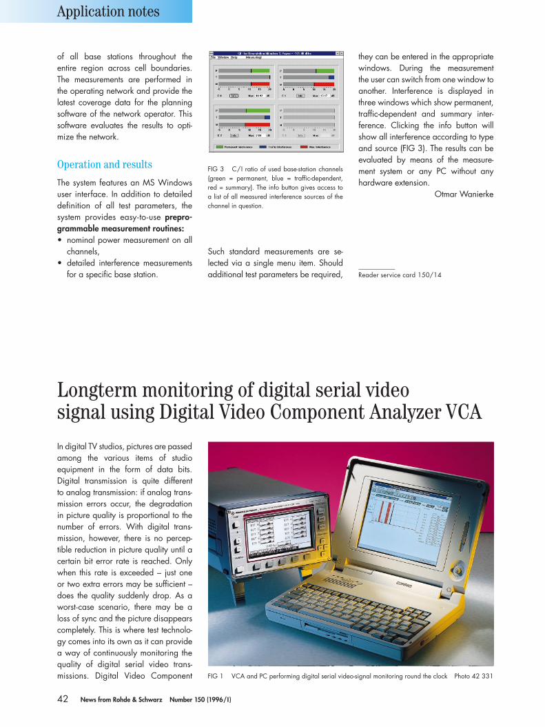
42 News from Rohde & Schwarz Number 150 (1996/I )
of all base stations throughout the entire region across cell boundaries.The measurements are performed in the operating network and provide thelatest coverage data for the planningsoftware of the network operator. Thissoftware evaluates the results to opti-mize the network.
Operation and results
The system features an MS Windowsuser interface. In addition to detaileddefinition of all test parameters, thesystem provides easy-to-use prepro-grammable measurement routines:• nominal power measurement on all
channels,• detailed interference measurements
for a specific base station.
Such standard measurements are se-lected via a single menu item. Shouldadditional test parameters be required,
they can be entered in the appropriatewindows. During the measurement the user can switch from one window toanother. Interference is displayed inthree windows which show permanent,traffic-dependent and summary inter-ference. Clicking the info button willshow all interference according to typeand source (FIG 3). The results can beevaluated by means of the measure-ment system or any PC without anyhardware extension.
Otmar Wanierke
Reader service card 150/14
Application notes
FIG 3 C/I ratio of used base-station channels(green = permanent, blue = traffic-dependent,red = summary). The info button gives access toa list of all measured interference sources of thechannel in question.
In digital TV studios, pictures are passedamong the various items of studioequipment in the form of data bits. Digital transmission is quite different to analog transmission: if analog trans-mission errors occur, the degradation in picture quality is proportional to thenumber of errors. With digital trans-mission, however, there is no percep-tible reduction in picture quality until acertain bit error rate is reached. Onlywhen this rate is exceeded – just one or two extra errors may be sufficient –does the quality suddenly drop. As aworst-case scenario, there may be aloss of sync and the picture disappearscompletely. This is where test technolo-gy comes into its own as it can providea way of continuously monitoring thequality of digital serial video trans-missions. Digital Video Component
Longterm monitoring of digital serial videosignal using Digital Video Component Analyzer VCA
FIG 1 VCA and PC performing digital serial video-signal monitoring round the clock Photo 42 331

43News from Rohde & Schwarz Number 150 (1996/I )
Analyzer VCA, developed by Rohde &Schwarz, fully meets these requirementsas it monitors the video signal in timewindows of approx. 10 seconds [1; 2].
Longterm, continuous monitoring is also required for errors that occur only rarely. When, say, a film is copiedfrom one tape deck to another, thecopy must be error-free. Visual inspec-tion would also take a considerablenumber of man hours (eg 2 to 10 h).This difficulty can be overcome by inte-grating VCA into a test and monitoringsystem specifically designed for thispurpose. VCA remote monitoring, aWindows application supports digitalvideo-signal monitoring around theclock thanks to the VCA measurementfunctions TRS (timing reference signal)and RCE (reserved code error) used to check the sync frame of the digitalvideo signal. This measurement cannotfind every bit error but it can be per-formed on live signals, ie on movingpictures. As an alternative the applica-tion provides a CRC (cyclic redundancycheck) monitoring function for digitalstills to detect sporadic bit errors in theactive picture area.
The hardware requirement is a PCwith the MS Windows operatingsystem and a VCA with a remote-control option (FIG 1). The values measured by VCA are read by the VCAremote monitoring program via the se-rial RS-232-C interface and processedso that the total number of errors isshown on the history display (FIG 2).Moreover, the individual errors are listed on the error-rate display and the measured values are stored in afile with a predefined name.
The File menu contains a number ofuseful functions to process measure-ments. Previous result protocols can bedisplayed again and checked with thecursor using the “Load old result” func-tion. The functions “Create ASCII errorlist” and “Create ASCII dataset” trans-form the result protocols into differentASCII tables so that the measured values can be analyzed by a database
program (eg MS Excel) to provide statistics or a better overview. If youreally want each and every error timestamped and documented, use “CreateASCII error list”. This gives a clear over-view of that part of the measurementwhich is of interest.
If transients of long duration are involved, it is often a good idea to increase the measurement time. VCAuses intervals between 2 and 10 s depending on the number of fields tobe measured. This time window can beincreased to 1 to 60 min. with “CreateASCII dataset”. This creates a tablewhich can be graphically processedlater using a database program. It is
then possible to display the transient response (of special interest whendeveloping studio equipment) in a waythat is easy to understand.
In the Measure menu, the measure-ment functions (TRS, RCE or CRC) arestarted by selecting the measurement orby clicking the appropriate icon. Theuser is then asked for the size of themeasurement window, the video-signalstandard (525 or 625 lines) and the file name. The measurement is stoppedby clicking the stop icon. A stoppedmeasurement can be continued bypressing the Cont icon (continue meas-
uring). The halt time is marked red andcan be taken into account at any laterstage of analysis.
The serial interface of the PC is con-figured in the Interface menu. The PCconfiguration and the VCA configura-tion must be the same. If not, the PCand the VCA will not be able to com-municate and an error message will be output.
The cursor functions make it easy tofind measured bit errors rapidly. Threecursor functions are available: go onepixel to the right or left on the screen,scroll one page to the right or left andplace cursor on the next error before orafter the current time. With the latterfunction the whole measurement is automatically checked for errors. This is especially important for longtermmeasurements in which only a few errors have occurred.
Martin Flach
REFERENCES
[1] Weigold, H.; Rohde, W.: Digital Video Com-ponent Analyzer VCA –Waveform monitorand signal analyzer for digital video signalsto CCIR 601. News from Rohde & Schwarz(1994) No. 145, pp 8 –10
[2] Osterloh, G.: Analysis of digital transportlayer with Video Analyzer VCA. News from Rohde & Schwarz (1995) No. 149, pp 40 –41
Reader service card 150/15 for further infor-mation on VCA
Application notes
FIG 2 Evaluation of longterm measurementwith error cluster at 10.50 h. Cursor function makes it easy to find times when errors occurred.
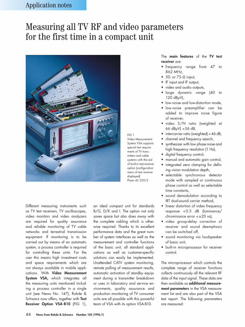
44 News from Rohde & Schwarz Number 150 (1996/I )
Different measuring instruments such as TV test receivers, TV oscilloscopes,video monitors and video analyzersare required for quality assurance and reliable monitoring of TV cable networks and terrestrial transmissionequipment. If monitoring is to be carried out by means of an automaticsystem, a process controller is requiredfor controlling these units. For the user this means high investment costsand space requirements which are not always available in mobile appli-cations. With Video MeasurementSystem VSA, which integrates all the measuring units mentioned includ-ing a process controller in a single unit (see News No. 147), Rohde &Schwarz now offers, together with TestReceiver Option VSA-B10 (FIG 1),
an ideal compact unit for standardsB/G, D/K and I. The option not onlysaves space but also does away withthe complete cabling which is other-wise required. Thanks to its excellentperformance data and the great num-ber of system interfaces as well as themeasurement and controller functionsof the basic unit, all standard appli-cations as well as customer-specific solutions can easily be implemented.Unattended CATV system monitoring,remote polling of measurement results,automatic activation of standby equip-ment during a transmitter breakdown or uses in laboratory and service en-vironments, quality assurance and production monitoring of TV consumerunits are all possible with this powerfulteam of VSA with its option VSA-B10.
The main features of the TV test receiver are:• frequency range from 47 to
862 MHz,• 50- or 75-Ω input,• IF input and IF output,• video and audio outputs,• large dynamic range (40 to
120 dBµV),• low-noise and low-distortion mode,• low-noise preamplifier can be
added to improve noise figure of receiver,
• video S/N ratio (weighted at 66 dBµV) >56 dB,
• intercarrier ratio (weighted) >46 dB,• channel and frequency search,• synthesizer with low phase noise and
high frequency resolution (1 Hz),• digital frequency control,• manual and automatic gain control,• integrated zero clamping for defin-
ing vision modulation depth,• selectable synchronous detector
mode with sampled or continuousphase control as well as selectabletime constants,
• sound demodulation according toIRT dual-sound carrier method,
• linear distortion of video frequencyresponse <0.5 dB (luminance/chrominance error <±20 ns),
• video group-delay correction of receiver and sound deemphasiscan be switched off,
• sound monitoring via loudspeakerof basic unit,
• built-in microprocessor for receivercontrol.
The microprocessor which controls thecomplete range of receiver functionscollects continuously all the relevant RFdata of the input signal. These data arethen available as additional measure-ment parameters in the VSA measure-ment list and are also part of the VSAtest report. The following parametersare measured:
Application notes
FIG 1 Video MeasurementSystem VSA supportsspecial test require-ments of TV trans-mitters and cablesystems with the aidof built-in test-receiveroption (configurationmenu of test receiverdisplayed)Photo 42 329/2
Measuring all TV RF and video parameters for the first time in a compact unit
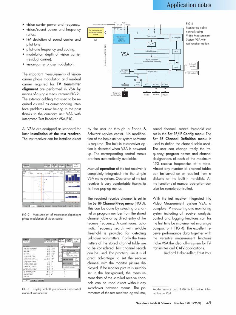
45News from Rohde & Schwarz Number 150 (1996/I )
• vision carrier power and frequency,• vision/sound power and frequency
ratios,• FM deviation of sound carrier and
pilot tone,• pilot-tone frequency and coding,• modulation depth of vision carrier
(residual carrier),• vision-carrier phase modulation.
The important measurements of vision-carrier phase modulation and residualcarrier required for TV transmitteralignment are performed in VSA bymeans of a single measurement (FIG 2).The external cabling that used to be re-quired as well as corresponding inter-face problems now belong to the pastthanks to the compact unit VSA with integrated Test Receiver VSA-B10.
All VSAs are equipped as standard forlater installation of the test receiver.The test receiver can be installed direct
by the user or through a Rohde &Schwarz service center. No modifica-tion of the basic unit or system softwareis required. The built-in test-receiver op-tion is detected when VSA is poweredup. The corresponding control menusare then automatically available.
Manual operation of the test receiver iscompletely integrated into the simpleVSA menu system. Operation of the testreceiver is very comfortable thanks toits three pop-up menus.
The required receive channel is set inthe Set RF Channel/Freq menu (FIG 3).This can be done by selecting a chan-nel or program number from the storedchannel table or by direct entry of thereceive frequency. A continuous, auto-matic frequency search with settablethreshold is provided for detecting unknown transmitters. If only the trans-mitters of the stored channel table areto be considered, fast channel searchcan be used. For practical use it is ofgreat advantage to set the receivechannel with the monitor picture dis-played. If the monitor picture is suitablyset in the background, the measure-ment data of the scrolled receive chan-nels can be read direct without anyswitchover between menus. The pa-rameters of the test receiver, eg volume,
sound channel, search threshold are set in the Set RF/IF Config menu. TheSet RF Channel Definition menu isused to define the channel table used.The user can change freely the fre-quency, program names and channeldesignations of each of the maximum150 receive frequencies of a table. Almost any number of channel tablescan be saved on or recalled from a diskette or the built-in harddisk. All the functions of manual operation canalso be remote-controlled.
With the test receiver integrated intoVideo Measurement System VSA, acomplete TV measuring and monitoringsystem including all receive, analysis,control and logging functions can forthe first time be implemented in a singlecompact unit (FIG 4). The excellent re-ceive performance data together withthe versatile measurement functionsmake VSA the ideal all-in system for TV-transmitter and CATV applications.
Richard Finkenzeller; Ernst Polz
Reader service card 150/16 for further infor-mation on VSA
Application notes
FIG 2 Measurement of modulation-dependent phase modulation of vision carrier
FIG 3 Display with RF parameters and controlmenu of test receiver
TV transmitter orbroadband cable
system
DUT
RFIF IF
AudioVideo
Test ReceiverOption
VSA-B10
Sys
tem
cont
rol (
IEC
62
5)
Video inputs
Full-field memory
Signal processor(measurement functions)
DOS processorIEC/IEEEbus
Programsand test data
Hard-disk
Printer Modem Mouse
LPT1 COM1 COM2
Externalmonitor
Ext. keyboard
LCD display
MUX
MUX
FIG 4 Monitoring cable network using Video Measurement System VSA with test-receiver option
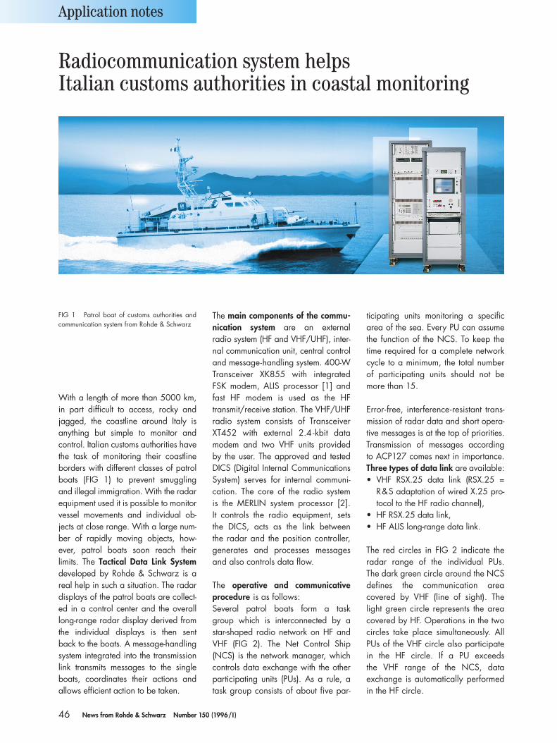
46 News from Rohde & Schwarz Number 150 (1996/I )
With a length of more than 5000 km,in part difficult to access, rocky andjagged, the coastline around Italy isanything but simple to monitor and control. Italian customs authorities havethe task of monitoring their coastlineborders with different classes of patrolboats (FIG 1) to prevent smuggling and illegal immigration. With the radarequipment used it is possible to monitorvessel movements and individual ob-jects at close range. With a large num-ber of rapidly moving objects, how-ever, patrol boats soon reach their limits. The Tactical Data Link Systemdeveloped by Rohde & Schwarz is areal help in such a situation. The radardisplays of the patrol boats are collect-ed in a control center and the overalllong-range radar display derived fromthe individual displays is then sent back to the boats. A message-handlingsystem integrated into the transmissionlink transmits messages to the singleboats, coordinates their actions and allows efficient action to be taken.
The main components of the commu-nication system are an external radio system (HF and VHF/UHF), inter-nal communication unit, central controland message-handling system. 400-WTransceiver XK855 with integrated FSK modem, ALIS processor [1] andfast HF modem is used as the HF transmit/receive station. The VHF/UHFradio system consists of TransceiverXT452 with external 2.4 -kbit data modem and two VHF units provided by the user. The approved and testedDICS (Digital Internal CommunicationsSystem) serves for internal communi-cation. The core of the radio system is the MERLIN system processor [2]. It controls the radio equipment, sets the DICS, acts as the link between the radar and the position controller,generates and processes messagesand also controls data flow.
The operative and communicativeprocedure is as follows:Several patrol boats form a task group which is interconnected by astar-shaped radio network on HF andVHF (FIG 2). The Net Control Ship (NCS) is the network manager, whichcontrols data exchange with the otherparticipating units (PUs). As a rule, atask group consists of about five par-
ticipating units monitoring a specific area of the sea. Every PU can assumethe function of the NCS. To keep thetime required for a complete networkcycle to a minimum, the total number of participating units should not bemore than 15.
Error-free, interference-resistant trans-mission of radar data and short opera-tive messages is at the top of priorities.Transmission of messages according to ACP127 comes next in importance.Three types of data link are available:• VHF RSX.25 data link (RSX.25 =
R&S adaptation of wired X.25 pro-tocol to the HF radio channel),
• HF RSX.25 data link,• HF ALIS long-range data link.
The red circles in FIG 2 indicate the radar range of the individual PUs. The dark green circle around the NCSdefines the communication area covered by VHF (line of sight). Thelight green circle represents the areacovered by HF. Operations in the twocircles take place simultaneously. AllPUs of the VHF circle also participatein the HF circle. If a PU exceeds the VHF range of the NCS, data exchange is automatically performedin the HF circle.
Application notes
FIG 1 Patrol boat of customs authorities andcommunication system from Rohde & Schwarz
Radiocommunication system helpsItalian customs authorities in coastal monitoring
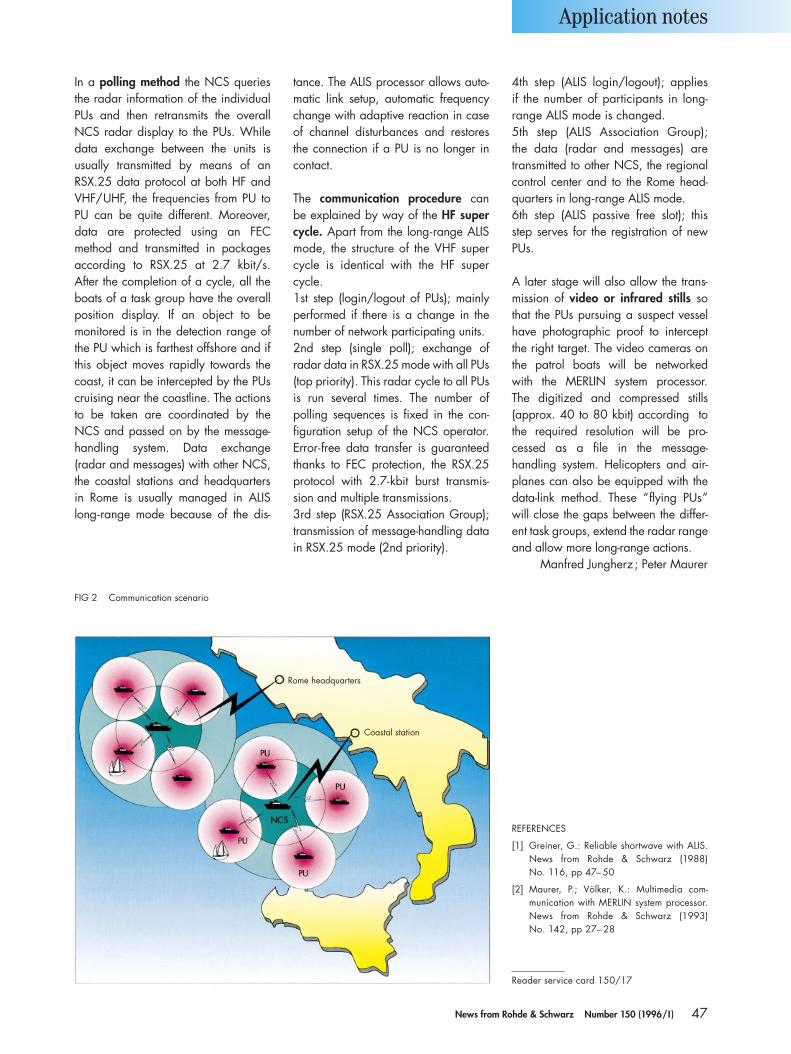
47News from Rohde & Schwarz Number 150 (1996/I )
In a polling method the NCS queriesthe radar information of the individualPUs and then retransmits the overallNCS radar display to the PUs. Whiledata exchange between the units is usually transmitted by means of anRSX.25 data protocol at both HF andVHF/UHF, the frequencies from PU toPU can be quite different. Moreover,data are protected using an FEC method and transmitted in packagesaccording to RSX.25 at 2.7 kbit/s. After the completion of a cycle, all theboats of a task group have the overallposition display. If an object to be monitored is in the detection range ofthe PU which is farthest offshore and ifthis object moves rapidly towards thecoast, it can be intercepted by the PUscruising near the coastline. The actionsto be taken are coordinated by theNCS and passed on by the message-handling system. Data exchange (radar and messages) with other NCS,the coastal stations and headquartersin Rome is usually managed in ALIS long-range mode because of the dis-
tance. The ALIS processor allows auto-matic link setup, automatic frequencychange with adaptive reaction in caseof channel disturbances and restoresthe connection if a PU is no longer incontact.
The communication procedure can be explained by way of the HF supercycle. Apart from the long-range ALISmode, the structure of the VHF super cycle is identical with the HF super cycle.1st step (login/logout of PUs); mainlyperformed if there is a change in thenumber of network participating units.2nd step (single poll); exchange of radar data in RSX.25 mode with all PUs(top priority). This radar cycle to all PUsis run several times. The number of polling sequences is fixed in the con-figuration setup of the NCS operator.Error-free data transfer is guaranteedthanks to FEC protection, the RSX.25protocol with 2.7-kbit burst transmis-sion and multiple transmissions.3rd step (RSX.25 Association Group);transmission of message-handling datain RSX.25 mode (2nd priority).
4th step (ALIS login/logout); applies if the number of participants in long-range ALIS mode is changed.5th step (ALIS Association Group); the data (radar and messages) aretransmitted to other NCS, the regionalcontrol center and to the Rome head-quarters in long-range ALIS mode.6th step (ALIS passive free slot); thisstep serves for the registration of newPUs.
A later stage will also allow the trans-mission of video or infrared stills sothat the PUs pursuing a suspect vesselhave photographic proof to interceptthe right target. The video cameras onthe patrol boats will be networked with the MERLIN system processor. The digitized and compressed stills (approx. 40 to 80 kbit) according tothe required resolution will be pro-cessed as a file in the message-handling system. Helicopters and air-planes can also be equipped with thedata-link method. These “flying PUs”will close the gaps between the differ-ent task groups, extend the radar rangeand allow more long-range actions.
Manfred Jungherz ; Peter Maurer
Application notes
FIG 2 Communication scenario
REFERENCES
[1] Greiner, G.: Reliable shortwave with ALIS.News from Rohde & Schwarz (1988) No. 116, pp 47– 50
[2] Maurer, P.; Völker, K.: Multimedia com-munication with MERLIN system processor.News from Rohde & Schwarz (1993) No. 142, pp 27– 28
Reader service card 150/17
Rome headquarters
Coastal station
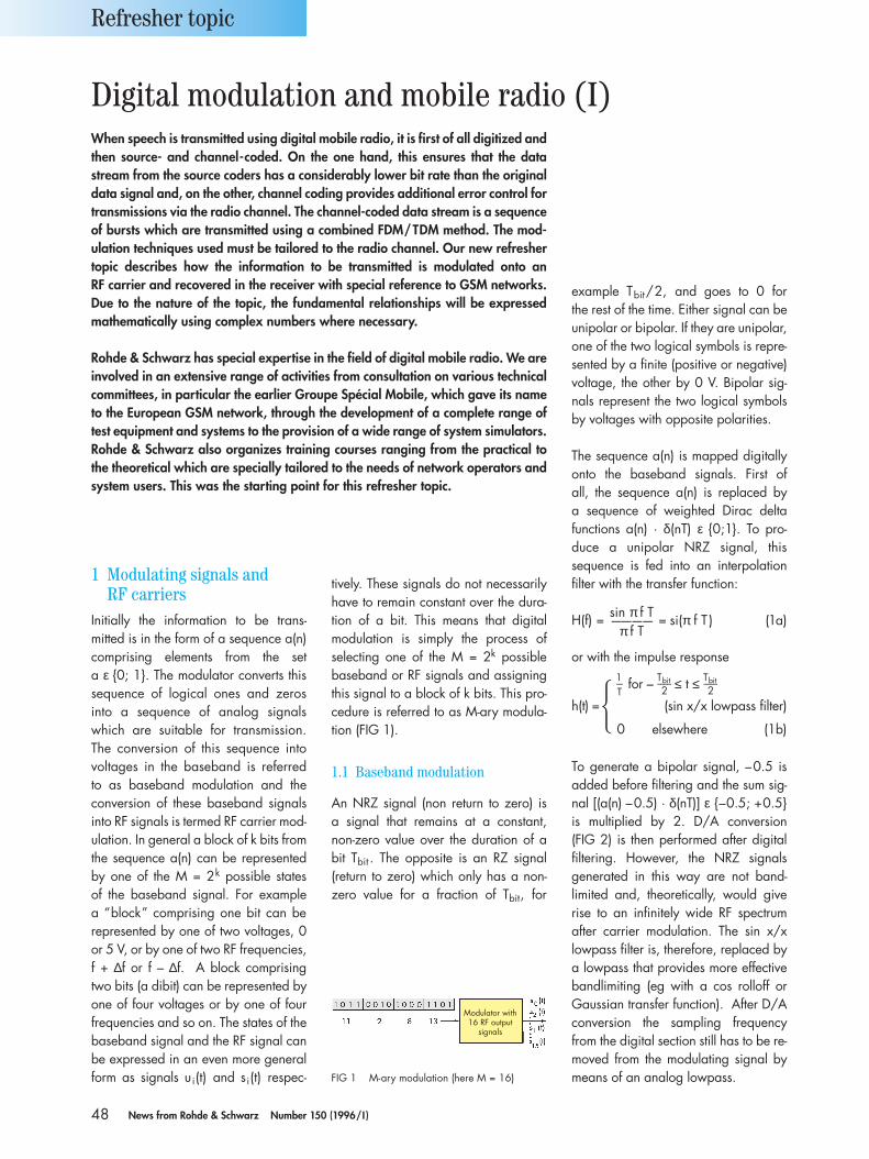
48 News from Rohde & Schwarz Number 150 (1996/I )
1 Modulating signals and RF carriers
Initially the information to be trans-mitted is in the form of a sequence a(n)comprising elements from the set a ε 0; 1. The modulator converts thissequence of logical ones and zeros into a sequence of analog signalswhich are suitable for transmission. The conversion of this sequence intovoltages in the baseband is referred to as baseband modulation and theconversion of these baseband signalsinto RF signals is termed RF carrier mod-ulation. In general a block of k bits fromthe sequence a(n) can be representedby one of the M = 2k possible states of the baseband signal. For example a “block” comprising one bit can be represented by one of two voltages, 0or 5 V, or by one of two RF frequencies,f + ∆f or f – ∆f. A block comprising two bits (a dibit) can be represented byone of four voltages or by one of fourfrequencies and so on. The states of thebaseband signal and the RF signal canbe expressed in an even more generalform as signals ui(t) and si(t) respec-
tively. These signals do not necessarilyhave to remain constant over the dura-tion of a bit. This means that digitalmodulation is simply the process of selecting one of the M = 2k possiblebaseband or RF signals and assigningthis signal to a block of k bits. This pro-cedure is referred to as M-ary modula-tion (FIG 1).
1.1 Baseband modulation
An NRZ signal (non return to zero) is a signal that remains at a constant, non-zero value over the duration of abit Tbit . The opposite is an RZ signal (return to zero) which only has a non-zero value for a fraction of Tbit, for
example Tbit/2, and goes to 0 for the rest of the time. Either signal can beunipolar or bipolar. If they are unipolar,one of the two logical symbols is repre-sented by a finite (positive or negative)voltage, the other by 0 V. Bipolar sig-nals represent the two logical symbolsby voltages with opposite polarities.
The sequence a(n) is mapped digitallyonto the baseband signals. First of all, the sequence a(n) is replaced by a sequence of weighted Dirac deltafunctions a(n) · δ(nT) ε 0;1. To pro-duce a unipolar NRZ signal, this sequence is fed into an interpolation filter with the transfer function:
sin π f TH(f) = ———— = si(π f T ) (1a)π f T
or with the impulse response1–T
for – Tbit––––2 ≤ t ≤ Tbit––––
2 h(t) =H (sin x/x lowpass filter)
0 elsewhere (1b)
To generate a bipolar signal, –0.5 isadded before filtering and the sum sig-nal [(a(n) –0.5) · δ(nT)] ε –0.5; +0.5is multiplied by 2. D/A conversion (FIG 2) is then performed after digitalfiltering. However, the NRZ signalsgenerated in this way are not band-limited and, theoretically, would giverise to an infinitely wide RF spectrum after carrier modulation. The sin x/xlowpass filter is, therefore, replaced bya lowpass that provides more effectivebandlimiting (eg with a cos rolloff orGaussian transfer function). After D/Aconversion the sampling frequencyfrom the digital section still has to be re-moved from the modulating signal bymeans of an analog lowpass.
Refresher topic
Digital modulation and mobile radio (I)When speech is transmitted using digital mobile radio, it is first of all digitized andthen source- and channel-coded. On the one hand, this ensures that the datastream from the source coders has a considerably lower bit rate than the originaldata signal and, on the other, channel coding provides additional error control fortransmissions via the radio channel. The channel-coded data stream is a sequenceof bursts which are transmitted using a combined FDM/TDM method. The mod-ulation techniques used must be tailored to the radio channel. Our new refreshertopic describes how the information to be transmitted is modulated onto an RF carrier and recovered in the receiver with special reference to GSM networks.Due to the nature of the topic, the fundamental relationships will be expressedmathematically using complex numbers where necessary.
Rohde & Schwarz has special expertise in the field of digital mobile radio. We areinvolved in an extensive range of activities from consultation on various technicalcommittees, in particular the earlier Groupe Spécial Mobile, which gave its nameto the European GSM network, through the development of a complete range oftest equipment and systems to the provision of a wide range of system simulators.Rohde & Schwarz also organizes training courses ranging from the practical tothe theoretical which are specially tailored to the needs of network operators andsystem users. This was the starting point for this refresher topic.
FIG 1 M-ary modulation (here M = 16)
Modulator with16 RF output
signals
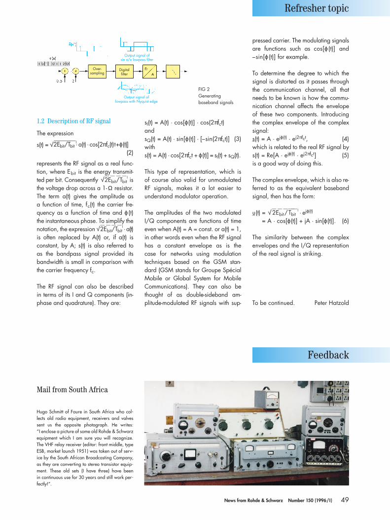
49News from Rohde & Schwarz Number 150 (1996/I )
1.2 Description of RF signal
The expression
s(t) = √—————l2Ebit/Tbit · a(t) · cos[2πfc(t)t+ϕ(t)](2)
represents the RF signal as a real func-tion, where Ebit is the energy transmit-ted per bit. Consequently √——
2Ebit/Tbit——l is
the voltage drop across a 1-Ω resistor.The term a(t) gives the amplitude as a function of time, fc(t) the carrier fre-quency as a function of time and ϕ (t)the instantaneous phase. To simplify thenotation, the expression √——
2Ebit/Tbit——l · a(t)
is often replaced by A(t) or, if a(t) is constant, by A; s(t) is also referred to as the bandpass signal provided itsbandwidth is small in comparison withthe carrier frequency fc.
The RF signal can also be described in terms of its I and Q components (in-phase and quadrature). They are:
sI(t) = A(t) · cos[ϕ(t)] · cos(2πfct)andsQ(t) = A(t) · sin[ϕ(t)] · [–sin(2πfct)] (3)withs(t) = A(t) · cos[2πfct + ϕ(t)] = sI(t) + sQ(t).
This type of representation, which is of course also valid for unmodulated RF signals, makes it a lot easier tounderstand modulator operation.
The amplitudes of the two modulatedI/Q components are functions of timeeven when A(t) = A = const. or a(t) = 1,in other words even when the RF signalhas a constant envelope as is the case for networks using modulationtechniques based on the GSM stan-dard (GSM stands for Groupe SpécialMobile or Global System for MobileCommunications). They can also bethought of as double-sideband am-plitude-modulated RF signals with sup-
pressed carrier. The modulating signalsare functions such as cos[ϕ (t)] and–sin[ϕ (t)] for example.
To determine the degree to which thesignal is distorted as it passes throughthe communication channel, all thatneeds to be known is how the commu-nication channel affects the envelope of these two components. Introducingthe complex envelope of the complexsignal:s(t) = A · ejϕ(t) · ej2πfct, (4)which is related to the real RF signal bys(t) = Re[A · ejϕ(t) · ej2πfct] (5)is a good way of doing this.
The complex envelope, which is also re-ferred to as the equivalent basebandsignal, then has the form:
u(t) = √——2Ebit/T
———–bit
l · ejϕ(t)
= A · cos[ϕ(t)] + jA · sin[ϕ(t)]. (6)
The similarity between the complex envelopes and the I/Q representationof the real signal is striking.
To be continued. Peter Hatzold
Refresher topic
Over-sampling
Digitalfilter
Output signal ofsin x/x lowpass filter
Output signal oflowpass with Nyquist edge
Feedback
Mail from South Africa
Hugo Schmitt of Faure in South Africa who col-lects old radio equipment, receivers and valvessent us the opposite photograph. He writes: “I enclose a picture of some old Rohde & Schwarzequipment which I am sure you will recognize.The VHF relay receiver (editor: front middle, typeESB, market launch 1951) was taken out of serv-ice by the South African Broadcasting Company,as they are converting to stereo transistor equip-ment. These old sets (I have three) have been in continuous use for 30 years and still work per-fectly!”.
FIG 2Generating baseband signals
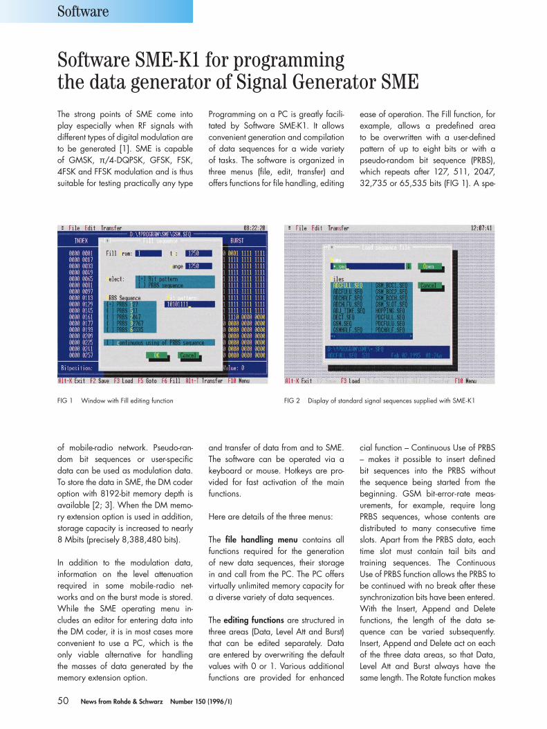
50 News from Rohde & Schwarz Number 150 (1996/I )
The strong points of SME come intoplay especially when RF signals withdifferent types of digital modulation areto be generated [1]. SME is capable of GMSK, π/4-DQPSK, GFSK, FSK, 4FSK and FFSK modulation and is thussuitable for testing practically any type
Programming on a PC is greatly facili-tated by Software SME-K1. It allowsconvenient generation and compilationof data sequences for a wide variety of tasks. The software is organized inthree menus (file, edit, transfer) and offers functions for file handling, editing
of mobile-radio network. Pseudo-ran-dom bit sequences or user-specific data can be used as modulation data.To store the data in SME, the DM coderoption with 8192-bit memory depth isavailable [2; 3]. When the DM memo-ry extension option is used in addition,storage capacity is increased to nearly8 Mbits (precisely 8,388,480 bits).
In addition to the modulation data, information on the level attenuation required in some mobile-radio net-works and on the burst mode is stored.While the SME operating menu in-cludes an editor for entering data intothe DM coder, it is in most cases moreconvenient to use a PC, which is the only viable alternative for handling the masses of data generated by thememory extension option.
and transfer of data from and to SME.The software can be operated via akeyboard or mouse. Hotkeys are pro-vided for fast activation of the mainfunctions.
Here are details of the three menus:
The file handling menu contains allfunctions required for the generation of new data sequences, their storage in and call from the PC. The PC offersvirtually unlimited memory capacity fora diverse variety of data sequences.
The editing functions are structured inthree areas (Data, Level Att and Burst)that can be edited separately. Data are entered by overwriting the defaultvalues with 0 or 1. Various additionalfunctions are provided for enhanced
cial function – Continuous Use of PRBS– makes it possible to insert defined bit sequences into the PRBS without the sequence being started from the beginning. GSM bit-error-rate meas-urements, for example, require longPRBS sequences, whose contents aredistributed to many consecutive timeslots. Apart from the PRBS data, eachtime slot must contain tail bits and training sequences. The ContinuousUse of PRBS function allows the PRBS tobe continued with no break after thesesynchronization bits have been entered.With the Insert, Append and Deletefunctions, the length of the data se-quence can be varied subsequently. Insert, Append and Delete act on eachof the three data areas, so that Data, Level Att and Burst always have thesame length. The Rotate function makes
ease of operation. The Fill function, forexample, allows a predefined area to be overwritten with a user-definedpattern of up to eight bits or with apseudo-random bit sequence (PRBS),which repeats after 127, 511, 2047,32,735 or 65,535 bits (FIG 1). A spe-
Software
Software SME-K1 for programming the data generator of Signal Generator SME
FIG 1 Window with Fill editing function FIG 2 Display of standard signal sequences supplied with SME-K1
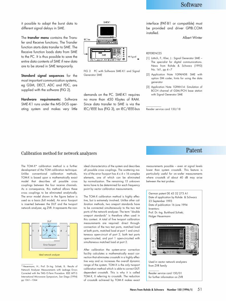
51News from Rohde & Schwarz Number 150 (1996/I )
it possible to adapt the burst data to different signal delays in SME.
The transfer menu contains the Trans-fer and Receive functions. The Transferfunction starts data transfer to SME. TheReceive function loads data from SMEto the PC. It is thus possible to save theentire data contents of SME if new dataare to be stored in SME temporarily.
Standard signal sequences for themost important communication systems,eg GSM, DECT, ADC and PDC, aresupplied with the software (FIG 2).
Hardware requirements: SoftwareSME-K1 runs under the MS-DOS oper-ating system and makes very little
demands on the PC. SME-K1 requiresno more than 450 Kbytes of RAM.Since data transfer to SME is via theIEC/IEEE bus (FIG 3), an IEC/IEEE-bus
interface (PAT-B1 or compatible) mustbe provided and driver GPIB.COM installed.
Albert Winter
REFERENCES
[1] Lüttich, F.; Klier, J.: Signal Generator SME –The specialist for digital communications.News from Rohde & Schwarz (1993) No. 141, pp 4 –7
[2] Application Note 1GPAN08: SME with option DM coder, hints for using the datagenerator
[3] Application Note 1GPAN14: Simulation ofBCCH channel of GSM/PCN base stationwith Signal Generator SME
Reader service card 150/18
Software
Patent
FIG 3 PC with Software SME-K1 and SignalGenerator SME
Calibration method for network analyzers
German patent DE 43 32 273 A1Date of application by Rohde & Schwarz 23 September 1993Date of publication 16 June 1994Inventors:Prof. Dr.-Ing. Burkhard Schiek; Holger Heuermann
Used in vector network analyzers from ZVR family
Reader service card 150/01 for further information on ZVR
The TOM-X* calibration method is a further development of the TOM calibration technique.Unlike conventional calibration methods, TOM-X is based upon a mathematically exactmodel that describes all possible crosscouplings between the four receive channels. As a consequence, this method allows thesecross couplings to be eliminated analytically.The error model shown in the figure below isused as a basis (full model). An error fourport is inserted between the DUT and the twoport network analyzer, eg ZVR. It represents the non-
ideal characteristics of the system and describesall possible cross couplings. The scattering ma-trix of the error fourport has 4 x 4 = 16 complexelements, one of which can be eliminated by normalization. The remaining 15 unknownterms have to be determined for each frequencypoint by vector calibration measurements.
The TOM-X calibration method is highly effec-tive, but is extremely involved. Unlike other cal-ibration methods, two oneport standards haveto be connected simultaneously to the two testports of the network analyzer. The term “doubleoneport standards” is therefore often used inthis context. A total of five twoport calibrationmeasurements are required: direct through-connection of the two test ports, matched loadat both ports, matched load at port 1 and simul-taneous open-circuit of port 2, both test portsopen-circuited, and port 1 open-circuited withsimultaneous matched load at port 2.
After calibration the system-error correction facility calculates a mathematically exact cor-rection that eliminates crosstalk in a highly effec-tive way and so increases the overall dynamicrange of the system. TOM-X is the only twoportcalibration method which is able to correct DUT-dependent crosstalk. This is why it is calledTOM-X, X referring to crosstalk. The reduction of crosstalk achieved by TOM-X makes exact
* Heuermann, H.; Prof. Dr.-Ing. Schiek, B.: Results of Network Analyzer Measurements with Leakage ErrorsCorrected with the TMS-15-Term Procedure. IEEE MTT-SInternational Microwave Symposium, San Diego (1994)pp 1361–1364
measurements possible – even at signal levelslower than system crosstalk. This feature is particularly useful for on-wafer measurementswhere crosstalk of about 40 dB may arisebetween the test probes.
DUT
Error fourport
Ideal network analyzer
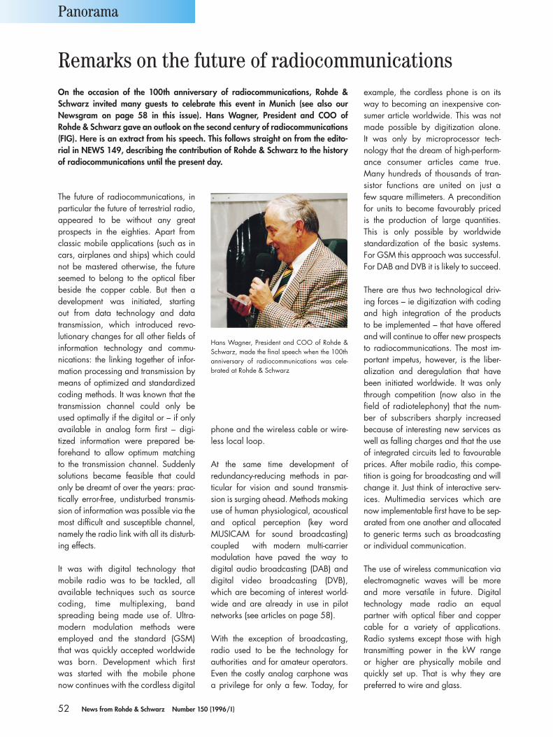
52 News from Rohde & Schwarz Number 150 (1996/I )
The future of radiocommunications, inparticular the future of terrestrial radio,appeared to be without any great prospects in the eighties. Apart fromclassic mobile applications (such as incars, airplanes and ships) which couldnot be mastered otherwise, the futureseemed to belong to the optical fiberbeside the copper cable. But then a development was initiated, starting out from data technology and datatransmission, which introduced revo-lutionary changes for all other fields ofinformation technology and commu-nications: the linking together of infor-mation processing and transmission bymeans of optimized and standardizedcoding methods. It was known that thetransmission channel could only beused optimally if the digital or – if only available in analog form first – digi-tized information were prepared be-forehand to allow optimum matching to the transmission channel. Suddenly solutions became feasible that couldonly be dreamt of over the years: prac-tically error-free, undisturbed transmis-sion of information was possible via the most difficult and susceptible channel,namely the radio link with all its disturb-ing effects.
It was with digital technology that mobile radio was to be tackled, allavailable techniques such as sourcecoding, time multiplexing, bandspreading being made use of. Ultra-modern modulation methods were employed and the standard (GSM)that was quickly accepted worldwidewas born. Development which firstwas started with the mobile phonenow continues with the cordless digital
phone and the wireless cable or wire-less local loop.
At the same time development of redundancy-reducing methods in par-ticular for vision and sound transmis-sion is surging ahead. Methods makinguse of human physiological, acousticaland optical perception (key word MUSICAM for sound broadcasting)coupled with modern multi-carriermodulation have paved the way to digital audio broadcasting (DAB) anddigital video broadcasting (DVB),which are becoming of interest world-wide and are already in use in pilot networks (see articles on page 58).
With the exception of broadcasting, radio used to be the technology for authorities and for amateur operators.Even the costly analog carphone was a privilege for only a few. Today, for
example, the cordless phone is on itsway to becoming an inexpensive con-sumer article worldwide. This was notmade possible by digitization alone. It was only by microprocessor tech-nology that the dream of high-perform-ance consumer articles came true.Many hundreds of thousands of tran-sistor functions are united on just a few square millimeters. A preconditionfor units to become favourably priced is the production of large quantities.This is only possible by worldwide standardization of the basic systems.For GSM this approach was successful.For DAB and DVB it is likely to succeed.
There are thus two technological driv-ing forces – ie digitization with codingand high integration of the products to be implemented – that have offeredand will continue to offer new prospectsto radiocommunications. The most im-portant impetus, however, is the liber-alization and deregulation that havebeen initiated worldwide. It was onlythrough competition (now also in thefield of radiotelephony) that the num-ber of subscribers sharply increased because of interesting new services aswell as falling charges and that the useof integrated circuits led to favourableprices. After mobile radio, this compe-tition is going for broadcasting and willchange it. Just think of interactive serv-ices. Multimedia services which arenow implementable first have to be sep-arated from one another and allocatedto generic terms such as broadcastingor individual communication.
The use of wireless communication viaelectromagnetic waves will be moreand more versatile in future. Digitaltechnology made radio an equal partner with optical fiber and coppercable for a variety of applications. Radio systems except those with hightransmitting power in the kW range or higher are physically mobile andquickly set up. That is why they are preferred to wire and glass.
Panorama
Hans Wagner, President and COO of Rohde &Schwarz, made the final speech when the 100thanniversary of radiocommunications was cele-brated at Rohde & Schwarz
Remarks on the future of radiocommunicationsOn the occasion of the 100th anniversary of radiocommunications, Rohde &Schwarz invited many guests to celebrate this event in Munich (see also our Newsgram on page 58 in this issue). Hans Wagner, President and COO of Rohde & Schwarz gave an outlook on the second century of radiocommunications(FIG). Here is an extract from his speech. This follows straight on from the edito-rial in NEWS 149, describing the contribution of Rohde & Schwarz to the historyof radiocommunications until the present day.
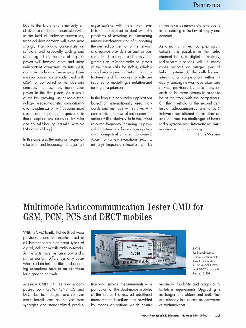
53News from Rohde & Schwarz Number 150 (1996/I )
Due to the future and practically ex-clusive use of digital transmission with-in the field of radiocommunications,technical developments will, even morestrongly than today, concentrate on software and especially coding andsignalling. The generation of high RFpower will become more and more unimportant compared to intelligent,adaptive methods of managing trans-mission power, as already used withGSM, or compared to methods andconcepts that use low transmissionpower in the first place. As a result of the fast growing use of radio tech-nology, electromagnetic compatibilityand its optimization will become moreand more important, especially in those applications reserved for wireand optical fiber (eg last mile, wirelessLAN or local loop).
In this case also the national frequencyallocation and frequency management
organizations will more than ever before be required to deal with theproblems of avoiding or eliminatingmutual interference and of supportingthe desired competition of the networkand service providers as best as pos-sible. The impelling use of highly inte-grated circuits in the radio equipmentof the future calls for stable, reliableand close cooperation with chip manu-facturers and for access to software required for modelling, simulation andtesting of equipment.
In the long run only radio applicationsbased on internationally used stan-dards and methods will survive. Anyconstraints in the use of radiocommuni-cations will exclusively lie in the limitedresource frequency including its physi-cal limitations as far as propagationand compatibility are concerned.Apart from a few exceptions (security,military) frequency allocation will be
shifted towards commercial and publicuse according to the law of supply anddemand.
As almost unlimited, complex appli-cations are possible in the radio channel thanks to digital technology,radiocommunications will in manycases become an integral part of hybrid systems. All this calls for realinternational cooperation within in-dustry, among network operators andservice providers but also betweeneach of the three groups in order tobe at the front with the competitors.On the threshold of the second cen-tury of radiocommunications Rohde &Schwarz has attuned to the situationand will face the challenges of futureradio systems and international part-nerships with all its energy.
Hans Wagner
Panorama
With its CMD family, Rohde & Schwarzprovides testers for mobiles used in all internationally significant types ofdigital, cellular mobile-radio networks.All the units have the same look and asimilar design. Differences only occurwhen certain test facilities and operat-ing procedures have to be optimizedfor a specific network.
A single CMD (FIG 1) now encom-passes both GSM/PCN/PCS andDECT test technologies and so evenmore benefit can be derived from synergies and standardized produc-
tion and service measurements – inparticular for the dual-mode mobilesof the future. The desired additionalmeasurement functions are providedby means of options which ensure
maximum flexibility and adaptabilityto future requirements. Upgrading isno longer a problem and units that are already in use can be converted at minimum cost.
Multimode Radiocommunication Tester CMD forGSM, PCN, PCS and DECT mobiles
FIG 1 Multimode radio-communication tester CMD for mobiles to GSM, PCN, PCS and DECT standardsPhoto 42 198
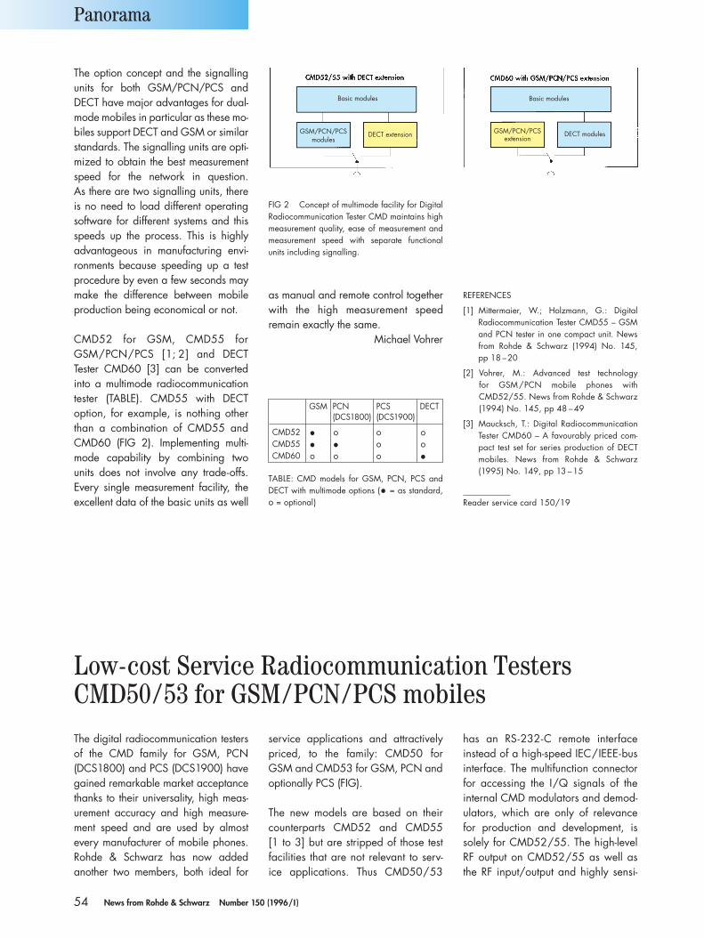
54 News from Rohde & Schwarz Number 150 (1996/I )
The option concept and the signallingunits for both GSM/PCN/PCS andDECT have major advantages for dual-mode mobiles in particular as these mo-biles support DECT and GSM or similarstandards. The signalling units are opti-mized to obtain the best measurementspeed for the network in question. As there are two signalling units, thereis no need to load different operating software for different systems and thisspeeds up the process. This is highly advantageous in manufacturing envi-ronments because speeding up a testprocedure by even a few seconds maymake the difference between mobileproduction being economical or not.
CMD52 for GSM, CMD55 for GSM/PCN/PCS [1; 2] and DECT Tester CMD60 [3] can be convertedinto a multimode radiocommunicationtester (TABLE). CMD55 with DECT option, for example, is nothing otherthan a combination of CMD55 andCMD60 (FIG 2). Implementing multi-mode capability by combining twounits does not involve any trade-offs.Every single measurement facility, theexcellent data of the basic units as well
as manual and remote control togetherwith the high measurement speed remain exactly the same.
Michael Vohrer
REFERENCES
[1] Mittermaier, W.; Holzmann, G.: Digital Radiocommunication Tester CMD55 – GSMand PCN tester in one compact unit. Newsfrom Rohde & Schwarz (1994) No. 145, pp 18 –20
[2] Vohrer, M.: Advanced test technology for GSM/PCN mobile phones withCMD52/55. News from Rohde & Schwarz(1994) No. 145, pp 48 –49
[3] Maucksch, T.: Digital RadiocommunicationTester CMD60 – A favourably priced com-pact test set for series production of DECTmobiles. News from Rohde & Schwarz(1995) No. 149, pp 13 –15
Reader service card 150/19
Panorama
GSM PCN PCS DECT(DCS1800) (DCS1900)
CMD52 • o o oCMD55 • • o oCMD60 o o o •
TABLE: CMD models for GSM, PCN, PCS andDECT with multimode options (• = as standard,o = optional)
FIG 2 Concept of multimode facility for DigitalRadiocommunication Tester CMD maintains highmeasurement quality, ease of measurement andmeasurement speed with separate functionalunits including signalling.
Basic modules
GSM/PCN/PCSextension
DECT modules
Basic modules
GSM/PCN/PCSmodules
DECT extension
Low-cost Service Radiocommunication Testers CMD50/53 for GSM/PCN/PCS mobilesThe digital radiocommunication testersof the CMD family for GSM, PCN (DCS1800) and PCS (DCS1900) havegained remarkable market acceptancethanks to their universality, high meas-urement accuracy and high measure-ment speed and are used by almostevery manufacturer of mobile phones.Rohde & Schwarz has now added another two members, both ideal for
service applications and attractivelypriced, to the family: CMD50 for GSM and CMD53 for GSM, PCN and optionally PCS (FIG).
The new models are based on theircounterparts CMD52 and CMD55 [1 to 3] but are stripped of those testfacilities that are not relevant to serv-ice applications. Thus CMD50/53
has an RS-232-C remote interface instead of a high-speed IEC/IEEE-businterface. The multifunction connectorfor accessing the I/Q signals of theinternal CMD modulators and demod-ulators, which are only of relevancefor production and development, issolely for CMD52/55. The high-levelRF output on CMD52/55 as well asthe RF input/output and highly sensi-

55News from Rohde & Schwarz Number 150 (1996/I )
tive second RF input for special moduleproduction tests are available as options for CMD50/53. This ensuresthat testing mobiles of the future whichmay have an integrated antenna andno RF connector will not be a problem.A DC ammeter/voltmeter with GSM-specific test curve is also available asan option.
grams, eg for production, can also be used for service testing. The bluebox gives a clear overview of all theavailable options and accessories forDigital Radiocommunication TesterCMD50/53.
With CMD50/53 a manufacturer ofmobiles not only has an attractive,
Panorama
All other facilities, technical data andoperation are identical for the fourunits. As a result, joint operation and replacement are straightforward and, if CMD52/55 is used for productiontesting and CMD50/53 for servicework, one can be absolutely certainthat the instruments’ responses are iden-tical and results are 100% consistent.Automatic, internal sequencing pro-
REFERENCES
[1] Mittermaier, W.; Holzmann, G.: Digital Ra-diocommunication Tester CMD55 – GSMand PCN tester in one compact unit. Newsfrom Rohde & Schwarz (1994) No. 145, pp 18 –20
[2] Vohrer, M.: Advanced test technology for GSM/PCN mobile phones withCMD52/55. News from Rohde & Schwarz(1994) No. 145, pp 48 –49
[3] Mittermaier, W.: Module test with DigitalRadiocommunication Tester CMD52/55.News from Rohde & Schwarz (1995) No. 149, pp 36 –37
Reader service card 150/20
GSM, PCN and PCS mobile Radiocommunica-tion Tester CMD53 for service and maintenanceat a favourable price Photo 42 288
OptionsCMD-B1 OCXO Reference OscillatorCMD-B3 Multi-Reference Frequency
Inputs/OutputsCMD-B4 Phase/Frequency Error,
Power Ramping and BER Measurement
CMD-B41 AF Measurement Unit withFrequency Counter
CMD-B42 Power Ramping Measurementwith High Dynamic Range
CMD-B43 GSM-SpectrumMeasurements
CMD-B62 Memory Card Interface (CMD-B6 also required)
CMD-B19 PCS Extension (for CMD53)CMD-B20 DC Ammeter/VoltmeterCMD-B30 High-Level RF Output,
Sensitive RF InputAccessoriesCMD-Z1 Formatted Memory CardCTD-Z10 Antenna Coupler with
Shielded ChamberSoftware CMD-K43 Narrowband Spectrum
Analysis
cost-effective solution for service appli-cations but can also enjoy the advan-tages of the coherent test philosophythat provides almost identical test tech-nology from module testing and finalproduction testing with CMD52/55 through to maintenance and servicewith CMD50/53.
Michael Vohrer
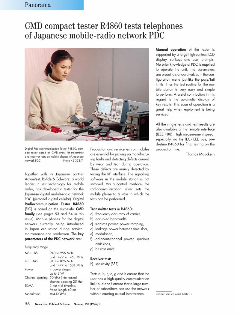
56 News from Rohde & Schwarz Number 150 (1996/I )
Together with its Japanese partner Advantest, Rohde & Schwarz, a worldleader in test technology for mobile radio, has developed a tester for the Japanese digital mobile-radio networkPDC (personal digital cellular). DigitalRadiocommunication Tester R4860(FIG) is based on the successful CMDfamily (see pages 53 and 54 in this issue). Mobile phones for the digitalnetwork currently being introduced in Japan are tested during service,maintenance and production. The key parameters of the PDC network are:
Frequency range
MS → BS 940 to 956 MHzand 1429 to 1453 MHz
BS → MS 810 to 826 MHzand 1477 to 1501 MHz
Power 4 power stages up to 3 W
Channel spacing 50 kHz (interleavedchannel spacing 25 Hz)
TDMA 2 out of 6 timeslots, frame length 40 ms
Modulation π/4-DQPSK
Production and service tests on mobilesare essential for picking up manufactur-ing faults and detecting defects causedby wear and tear during operation.These defects are mainly detected bytesting the RF interface. The signallingsoftware in the mobile station is not involved. Via a control interface, the radiocommunication tester sets the mobile phone to a state in which thetests can be performed.
Transmitter tests in R4860:a) frequency accuracy of carrier,b) occupied bandwidth,c) transmit power, power ramping,d) leakage power between time slots,e) modulation,f) adjacent-channel power, spurious
emissions,g) bit rate error.
Receiver test:h) sensitivity (BER).
Tests a, b, c, e, g and h ensure that theuser has a high-quality communicationlink; b, d and f ensure that a large num-ber of subscribers can use the networkwithout causing mutual interference.
Manual operation of the tester is supported by a large high-contrast LCDdisplay, softkeys and user prompts. No prior knowledge of PDC is requiredto operate the unit. The parameters are preset to standard values in the con-figuration menu just like the pass/fail limits. Thus the test routine for the mo-bile station is very easy and simple to perform. A useful contribution in thisregard is the automatic display of key results. This ease of operation is agreat help when equipment is beingserviced.
All the single tests and test results are also available at the remote interface(IEEE 488). High measurement speed,especially via the IEC/IEEE bus, pre-destine R4860 for final testing on theproduction line.
Thomas Maucksch
Panorama
Digital Radiocommunication Tester R4860, com-pact tester based on CMD units, for transmitterand receiver tests on mobile phones of Japanesenetwork PDC Photo 42 333/1
CMD compact tester R4860 tests telephonesof Japanese mobile-radio network PDC
Reader service card 150/21
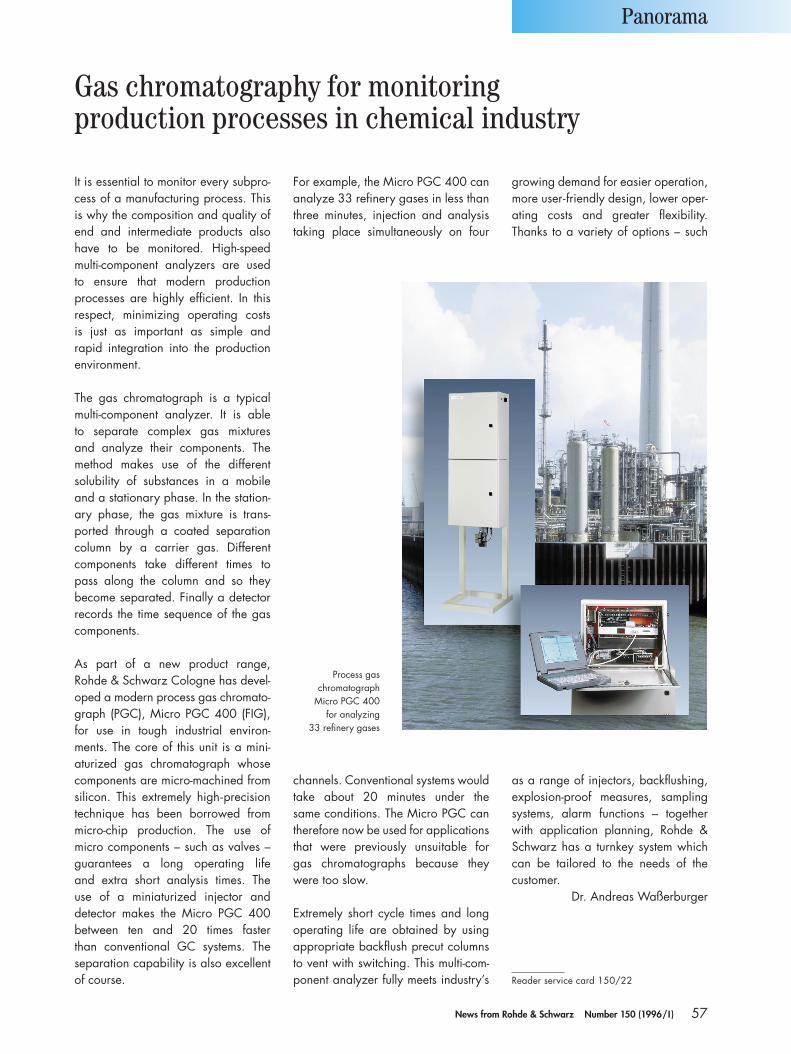
57News from Rohde & Schwarz Number 150 (1996/I )
It is essential to monitor every subpro-cess of a manufacturing process. Thisis why the composition and quality ofend and intermediate products alsohave to be monitored. High-speed multi-component analyzers are used to ensure that modern production processes are highly efficient. In thisrespect, minimizing operating costs is just as important as simple and rapid integration into the productionenvironment.
The gas chromatograph is a typicalmulti-component analyzer. It is able to separate complex gas mixtures and analyze their components. Themethod makes use of the different solubility of substances in a mobileand a stationary phase. In the station-ary phase, the gas mixture is trans-ported through a coated separationcolumn by a carrier gas. Differentcomponents take different times topass along the column and so they become separated. Finally a detectorrecords the time sequence of the gascomponents.
As part of a new product range, Rohde & Schwarz Cologne has devel-oped a modern process gas chromato-graph (PGC), Micro PGC 400 (FIG),for use in tough industrial environ-ments. The core of this unit is a mini-aturized gas chromatograph whosecomponents are micro-machined fromsilicon. This extremely high-precisiontechnique has been borrowed from micro-chip production. The use of micro components – such as valves –guarantees a long operating life and extra short analysis times. The use of a miniaturized injector and detector makes the Micro PGC 400between ten and 20 times faster than conventional GC systems. Theseparation capability is also excellentof course.
For example, the Micro PGC 400 cananalyze 33 refinery gases in less thanthree minutes, injection and analysistaking place simultaneously on four
growing demand for easier operation,more user-friendly design, lower oper-ating costs and greater flexibility.Thanks to a variety of options – such
Panorama
channels. Conventional systems wouldtake about 20 minutes under the same conditions. The Micro PGC cantherefore now be used for applicationsthat were previously unsuitable for gas chromatographs because theywere too slow.
Extremely short cycle times and longoperating life are obtained by usingappropriate backflush precut columnsto vent with switching. This multi-com-ponent analyzer fully meets industry’s
as a range of injectors, backflushing,explosion-proof measures, samplingsystems, alarm functions – togetherwith application planning, Rohde &Schwarz has a turnkey system whichcan be tailored to the needs of the customer.
Dr. Andreas Waßerburger
Reader service card 150/22
Gas chromatography for monitoringproduction processes in chemical industry
Process gas chromatograph
Micro PGC 400 for analyzing
33 refinery gases
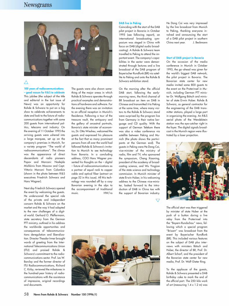
58 News from Rohde & Schwarz Number 150 (1996/I )
100 years of radiocommunications– good reason for R&S to celebrateThis jubilee (the subject of the titleand editorial in the last issue ofNews) was an opportunity for Rohde & Schwarz to put on a bigshow to celebrate achievements todate and look to the future of radio-communications together with some200 guests from international pol-itics, telecoms and industry. On the evening of 11 October 1995 the arriving guests were ushered into a large marquee, set up on thecompany’s premises in Munich, fora variety program “The world ofradiocommunications”. The climaxwas the appearance of direct descendants of radio pioneers Popov and Marconi: NadejdaMishkinis from Moscow and Capt.Vittorio Marconi from Colombia (shown in the photo between R&Sexecutives Friedrich Schwarz andHans Wagner).
Next day Friedrich Schwarz openedthe event by welcoming the guests.He underscored the special role of the private and independent concern Rohde & Schwarz on themarket and the way it had adaptedto the new challenges of a digit-al world. Gerhard O. Pfeffermann,state secretary from the GermanPTT ministry, outlined in his addressthe worldwide opportunities andconsequences of telecommunica-tions deregulation and liberaliza-tion. Director Theodor Irmer broughtwords of greeting from the Inter-national Telecommunications Union(ITU) and praised Rohde &Schwarz’s commitment to the radio-communications sector. Prof. Les W.Barclay and the former director ofITU Radiocommunications, RichardC. Kirby, reviewed the milestones inthe hundred-year history of radio-communications with the assistanceof impressive, original recordingsand documents.
The guests were also shown some-thing of the major areas in whichRohde & Schwarz operates throughpractical examples and demonstra-tions of hardware and software. Forthe evening there was an invitationto an official reception in Munich’sResidence. Following a tour of thetreasure vault, the antiquary andthe gallery of ancestral portraits,Bavaria’s state minister of econom-ics, Dr. Otto Wiesheu, welcomed theguests and expressed his pleasureat the fact that so many prominentpersons from all over the world hadfollowed Rohde & Schwarz’s invita-tion to Munich to see technologyfrom Bavaria. In a concluding address, COO Hans Wagner pre-sented his thoughts on the – digital– future of radiocommunications asa partner of equal rank to coppercable and optical fiber (extract on page 52 in this issue). All this tech-nology was rounded off by a cosyBavarian evening in the alps to the accompaniment of traditionalmusic. HW/ro
DAB live in PekingCoinciding with the start of the DABpilot project in Bavaria in October1995 (see following report), aninternational broadcasting sym-posium was staged in China withfocus on DAB (digital audio broad-casting). A Rohde & Schwarz teamtravelled to Peking to attend the im-portant event. The company’s capa-bilities in the sector were demon-strated through lectures and a livebroadcast of the DAB program ofBayerischer Rundfunk (BR) via satel-lite to Peking and onto the Rohde &Schwarz exhibition stand.
On the morning after the officialDAB start, following the early-morning news, the third channel ofBR broadcast an item on DAB inChinese and transmitted it to Pekingat the same time, where many visi-tors to the Rohde & Schwarz standwere surprised by the program livefrom Germany in their native lan-guage and CD quality. With thesupport of German Telekom therewas also a video conference viasatellite between Peking and Mu-nich (the photo shows the partici-pants at the German end). Theguests in Peking were He Dong Cai,vice-minister of the ministry of radio, film and TV, who sponsoredthe symposium, Cheng Xiaoning,president of the academy of broad-casting science, and Wu Yingjian of the state science and technologycommission. In Munich minister ofstate Erwin Huber, in his welcomingaddress to the Chinese vice-minis-ter, looked forward to the intro-duction of DAB in China too withthe support of Bavarian industry.
Newsgrams
Start of DAB project in BavariaOn the occasion of the media conference in Munich in October1995, the go-ahead was given forthe world’s biggest DAB network,the pilot project in Bavaria. The Bavarian state center for new media invited some 800 guests tothe event on the Praterinsel in Mu-nich, including German PTT minis-ter Dr. Wolfgang Bötsch and minis-ter of state Erwin Huber. Rohde &Schwarz, as general contractor forthe engineering of the DAB trans-mitter stations, played a large partin organizing the evening. An R&Saerial photo of the Wendelstein station was the eye-catcher right inthe foyer. The digital signals broad-cast in the Munich region were illus-trated by a laser projection.
The official start was then triggeredby minister of state Huber at thepush of a button during a live relay from the Praterinsel into the “Bayern-Rundschau” news, fol-lowing which a special program“Brisant ” was broadcast from theevent by Bayerischer Rundfunk(BR). This included various featureson the subject of DAB plus inter-views with ministers Bötsch andHuber, the director of BR, Prof. Dr.Albert Scharf, and the president ofthe Bavarian state center for newmedia, Prof. Dr. Wolf-Dieter Ring.
To the applause of the guests, Rohde & Schwarz presented a DABbirthday cake to mark the end ofthe official part. The 250-kilo workof art (measuring 1.4 x 1.2 m) was
He Dong Cai was very impressedby the live broadcast from Munichto Peking, thanking everyone in-volved and announcing the start of a DAB pilot project in southernChina next year. J. Beckmann
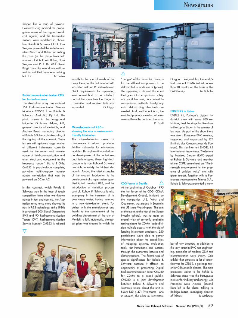
59News from Rohde & Schwarz Number 150 (1996/I )
shaped like a map of Bavaria.Coloured icing marked the propa-gation areas of the digital broad-cast signals, and the transmitter stations were modelled in choco-late. Rohde & Schwarz COO HansWagner presented the knife to min-isters Bötsch and Huber for cuttingthe cake (in the photo from left: minister of state Erwin Huber, HansWagner and Prof. Dr. Wolf-DieterRing). The cake went down well, sowell in fact that there was nothingleft of it. N. Julien
Microelectronics at R&S – showing the way in environment-friendly fabricationThe microelectronics center of competence in Munich producesthinfilm substrates for microwavemodules. Through continuous follow-on development of the techniquesand technologies, these high-techcomponents from Rohde & Schwarzare able to satisfy the highest de-mands. Among the latest examplesof the modern fabrication is the development of a layer system qual-ified to MIL standard 883, and theintroduction of statistical processcontrol. Rohde & Schwarz is alsoexemplary in the treatment of itsown waste water, having investedin a new detoxication plant. To-gether with the manufacturer andthanks to the commitment of thebuilding department of the city ofMunich, a fully automatic, biologi-cal plant was created in which the
“hunger” of the anaerobic biomassfor the effluent components to bedetoxicated is made use of (photo).The operating costs and the effortthat goes into occupational safetyare small because, in contrast toconventional methods, hardly anyextra detoxicating chemicals areneeded. And, last but not least, theenriched precious metals can be re-covered from the perished biomass.
R. Frodl
Oregon – designed this, the world’sfirst compact CDMA test set, in lessthan 18 months on the basis of theCMD family. M. Scholla
Newsgrams
Radiocommunication testers CMSfor Australian armyThe Australian army has ordered154 Radiocommunication ServiceMonitors CMS53 from Rohde &Schwarz (Australia) Pty Ltd. Thephoto shows in the foregroundbrigadier Grahame Hellyer, AM,general director of materials, andAndrew Bean, managing directorof Rohde & Schwarz in Australia, atthe signing of the contract. Thesetest sets will replace a large numberof different instruments currentlyused for the repair and mainte-nance of field-communication andother electronic equipment in thefrequency range 1 Hz to 1 GHz.CMS53 is practically a complete,portable multi-purpose mainte-nance workstation that can be powered on DC or AC.
In this contract, which Rohde &Schwarz won in the face of toughcompetition from other well-knownnames in test engineering, the Aus-tralian army once more showed itstrust in R&S technology. In the 1980sit purchased 300 Signal GeneratorsSMS and 90 RadiocommunicationTesters CMT. RadiocommunicationService Monitor CMS53 is tailored
exactly to the special needs of thearmy. Here, for the first time, a CMSwas fitted with an RF millivoltmeter.Strict requirements for operating environment had to be satisfied,and at the same time the range oftransmitter and receiver tests wasexpanded. G. Higgs
CDG forum in SeattleAt the beginning of October 1995the first forum of the CDG (CDMADevelopment Group), initiated bythe companies U.S. West and Qualcomm, was staged in Seattle inthe US state Washington. The aimof the event, at the foot of the SpaceNeedle (photo), was to gain anoverall view of currently availabletesting means for CDMA (code-divi-sion multiple access) with the aid ofleading instrument producers. 250participants were able to gather information about the capabilitiesof mapping systems, evaluationtools, test instruments and systemsthrough the numerous lectures anddemonstrations. The forum was ofspecial significance for Rohde &Schwarz because it offered an opportunity of presenting DigitalRadiocommunication Tester CMD80for CDMA to a broad public.CMD80 is a joint developmentbetween Rohde & Schwarz and Tektronix (more about the unit inNews 149, p 47). Two teams – onein Munich, the other in Beaverton,
ENDIEL 95 in LisbonENDIEL 95, Portugal’s biggest in-dustrial show with some 200 ex-hibitors, held the stage for five daysin the capital Lisbon in the summer oflast year. As part of the show therewas also a European EMC seminar,supported and organized by ICP (Instituto das Comunicacoes de Por-tugal). This seminar lent ENDIEL 95international importance. The lectureby Manfred Stecher (EMC expert at Rohde & Schwarz and member of the CISPR committee) on “Field-strength measurement in the pres-ence of ambient noise” met withgreat interest. Together with its Por-tuguese representative Telerus S.A.,Rohde & Schwarz presented a num-
ber of new products. In addition tothe very latest in EMC test engineer-ing, examples of modern GSM testinstrumentation were shown. Oneexhibit that attracted a lot of atten-tion was the CTD52, a go/nogo test-er for GSM mobile phones. The mostprominent visitor to the Rohde &Schwarz stand was the Portugueseminister for industry and energy, LuisFernando Mira Amaral (secondfrom left in the photo, talking to Rodrigo Leitão, managing directorof Telerus). B. Mohacsy
60 News from Rohde & Schwarz Number 150 (1996/I )
Vector Network Analyzers ZVR (for all measure-ments and new calibration methods such as TOM-X), ZVRE (for magnitude and phase of all s-parameters) and ZVRL (for magnitude and phaseof s11 and s21) are extremely sensitive and have a refresh rate of over 25 frames/s; 9 kHz (10 Hzwith option) to 4 GHz, resolution 10 µHz, dynam-ic range (with option) >130 dB, reference channel(ZVR: 2), calibration time <20 s, automatic two-port calibration; numerous options (eg computerfunction).
Data sheet PD 757.1802.21 enter 150/01
Digital Radiocommunication Tester CMD60(DECT) performs fast RF tests to CTR06 (up-gradable for GSM, DCS1800 and DCS1900); RS-232-C interface, AF tests and IEC/IEEE-businterface with options.
Data sheet PD 757.1731.21 enter 150/23
Digital Radiocommunication Tester CMD80 is acompact tester for CDMA mobile stations (IS 95)including power supplies; RS-232-C interface (IEC/IEEE bus as option).
Data sheet PD 757.1825.21 enter 150/24
Digital Radiocommunication Test Sets CRTP02,CRTC02; the data sheet now includes CRTC02 for mobile stations to GSM, DCS1800 andDCS1900.
Data sheet PD 757.0058.22 enter 150/25
EMI Test Receiver ESPC (150 kHz to 1 GHz,optional range extensions to 9 kHz and 2.05 GHz)for interference weighting to CISPR16-1 (10 HzPRF) and measurements to commercial EMIstandards; powered from internal (option) or external battery.
Data sheet PD 757.2009.21 enter 150/26
Microwave Signal Generator SMP (0.01/2 to 40 GHz); the revised data sheet now also featuresmodels 03 (27 GHz) and 04 (40 GHz).
Data sheet PD 757.0935.21 enter 150/04
Universal Shielding Chamber CTD-Z10 with An-tenna Coupler for Mobile Radio (900-MHz band)for interference-free testing on all cellular net-works; attenuation >50 dB.
Data sheet PD 757.1960.21 enter 150/27
EMI Software ESxS-K1 for receiver family ESS/ESHS/ESVS is user-friendly and operates underWindows 3.1 (80836 or higher).
Data sheet PD 757.1848.21 enter 150/28
Sound and TV Broadcasting System STARS (87.5to 108/470 to 860 MHz) for use in inaccessibleareas and under harsh climatic conditions convertssatellite signals to terrestrial frequencies (transmitpower of 10 W for TV and 20 W for VHF); powersupply 1200 VA.
Data sheet PD 757.1948.21 enter 150/29
VHF-UHF Search Receiver ESMA (20 to 1300 MHz) is the perfect central unit for fast (5 GHz/s) and precise radiomonitoring; high sen-sitivity, tracking preselection, large dynamic range,measures frequency offset and short-duration signals, optional data analysis, can be poweredboth from AC line and battery.
Data sheet PD 757.1719.21 enter 150/30
Solutions for Coverage Measurements. This bro-chure gives an overview of the coverage measure-ment systems of the TS9950 family for planning,optimization and maintenance of digital radio networks.
Info PD 757.1925.21 enter 150/31
Listen. Locate. Analyze. This brochure deals withradiomonitoring and radiolocation and showswhy Rohde & Schwarz is the ideal partner forsystem solutions.
Info PD 757.1954.21 enter 150/32
Encoder Test Sequence DVTS (JPEG, MPEG). Thismodule contains static and moving picture ele-ments for encoder quality assessment.
Info PD 757.1790.21 enter 150/33
Documentation – mediator between man andtechnology. The R & S Cologne Plant guaranteesthat its documentation complies with legal pro-visions and enhances user safety.
Info PD 757.2015.11 enter 150/34
New application notes
Automatic measurements on tape recorders usingAudio Analyzer UPD
Appl 1GPAN19E enter 150/35
IEC/IEEE-bus control of Audio Analyzer UPD
Appl 1GPAN22E enter 150/36
Measurements of dual-tone multifrequency diallingsignals with Audio Analyzer UPD
Appl 1GPAN23E enter 150/37
Measurements on tuners using Audio AnalyzerUPD and Signal Generator SMT
Appl 1GPAN24E enter 150/38
Base-station adjacent timeslot rejection measure-ment with CMD and SME
Appl 1GPAN26E enter 150/39Schz
Information in print
Booktalk Der deutsche RundfunkFaszination einer technischen Entwicklung
by Siegfried Hermann, Wolf Kahle and Joachim Kniestedt. Published 1994 by R. v.Decker’s Verlag, G. Schenck, Heidelberg. ISBN 3-7685-2394-2, 288 pages, more than200 illustrations (six of them from Rohde &Schwarz), available in bookshops, price DM 65(only in German).
This book was produced in cooperation with German Telekom and shows that its predecessor,the PTT, laid the foundation for the technical development of broadcasting. Joachim Kniestedt,familiar as an author of numerous articles on the technology and history of sound and TVbroadcasting, reports on the beginning of broadcasting and its development up to 1989 inWest Germany. In the chapter “ The ultra-short-wave for broadcasting – the wave of joy” there is
mention of the achievements of Rohde & Schwarzin this field.
Dr. Siegfried Hermann, a scientific assistant inbroadcasting in East Germany up to the time ofreunification, reports on the development ofbroadcasting there after 1945. Joachim Kniestedtreturns to talk of broadcasting in a unified Germany and international regulations govern-ing the use of broadcast frequencies. Dr. WolfKahle, who long worked for the state broad-caster in Weimar, for Berliner Rundfunk and the German PTT, explains the broadcast studioengineering of the German PTT.
The book is interesting for both specialists andthose with a general interest in broadcasting.
61News from Rohde & Schwarz Number 150 (1996/I )
Press comments
At the right time
Andreas Schümchen of »Medien-Bulletin« spokein issue 8/95 to Franz Dosch, executive vicepresident of the sound and TV broadcasting di-vision at Rohde & Schwarz, about the challengesfacing broadcasters:
DAB is a long due innovation in sound broad-casting. It is a European development and invest-ment, and so we are committed to implement it in Europe… From the source coding in the studiothrough satellite up-links and down-links to terres-trial transmitting components, we offer every-thing needed to create a complete, synchronizedbroadcasting network. On the subject of DBV(digital television): … We have already imple-mented a pilot project in Switzerland, the combi-nation of a PAL transmitter with a DVB transmitterthat broadcasts terrestrially and can be switchedby telephone modem to analog PAL or DVB. The Swiss PTT is using this project to investigatecoverage quality. All our analog TV transmittersare already designed today so that they can godigital without any modification.
Online measurement for the environmentThe magazine »CHEManager« 9/95 reportedon the ENVITEC 95 show:
Rohde & Schwarz presented a new online me-tering method for combustion aerosols. Using theCT-500 immission meter, PAH particles can bedetected so that PAH emissions can be traced, lo-calized and quantified like immissions, and loadratios and components can be judged reliably.
Signal Generator SME appeared all of four timeson the cover of » Mercado Electronica« 23/95,published in Argentina. In the same issue therewas an article by Rohde & Schwarz on the new IEC/IEEE-bus command language SCPI forremotely controlling instruments, making thework of the user very much simpler.
Modern receiver for EMC
In »EMC Journal« 3/95 Wolf Schreyer, productmanager for signal analysis and EMC T&M prod-ucts at Rohde & Schwarz, gave a summary of thesituation shortly before the entering into force ofthe German EMC act on 1 January 1996, present-ing at the same time the concept of Rohde &Schwarz’s Precertification Test Receiver ESPC:
The development of electronic products is muchtoo costly nowadays to leave the final result, evenin part, to chance. This naturally also applies tothe interference emitted by such products, which,once the transition period expires on 1 January1996, will be subject once and for all to the Ger-man EMC act (EMVG) and is due to become a headache for many manufacturers, mainly medium-sized businesses. Now that awareness of the need for such emission measurements has woken from its long sleep, test engineeringhas adapted to the situation. ESPC sticks outamong the mass of precompliance receivers,and to emphasize the fact it has been dubbed a precertification test receiver. The risk of unsatis-factory or even unusable test results is much smaller, an encouraging factor for those who are not familiar with all the tricks and ruses ofinterference measurement.
Quality for the future
On the subject of ISO 9000 at Rohde & Schwarz,editor Paul Kho interviewed the director of thecentral quality department, Manfred Fleisch-mann, for »Konstruktionspraxis« 8/95:
Rohde & Schwarz got its ISO 9001 certificate in1992. That was just the beginning of further im-provement of quality within the company. Not justso that the following audits could be surmounted,but above all for an internal quality policy thatwill ensure lasting satisfaction of all customers.
Multifunctional communication
The new Accessnet ® digital exchange from R&SBick Mobilfunk was a subject for the communi-cations magazine »NET« 8-9/95:
Wireless business and administrative communi-cation will now be even more flexible on theAccessnet® radiocommunication system. A newdigital exchange allows simultaneous operationof analog and digital trunked-radio channels. Anetwork operator can therefore continue to usehis existing Accessnet infrastructure and flexiblyintegrate a modern digital system step by step.
»praktiker«, an Austrian magazine for multi-media and electronics, showed the Inmarsat-M radiophone SP1600 from Rohde & Schwarz onthe cover of its July/August 1995 issue and devoted an article to the purpose and use of this modern radio system.
Spectrum Analyzer FSE from Rohde & Schwarzis used to being a cover star, like on the Dutchmagazine »Elektronica« 9/95.
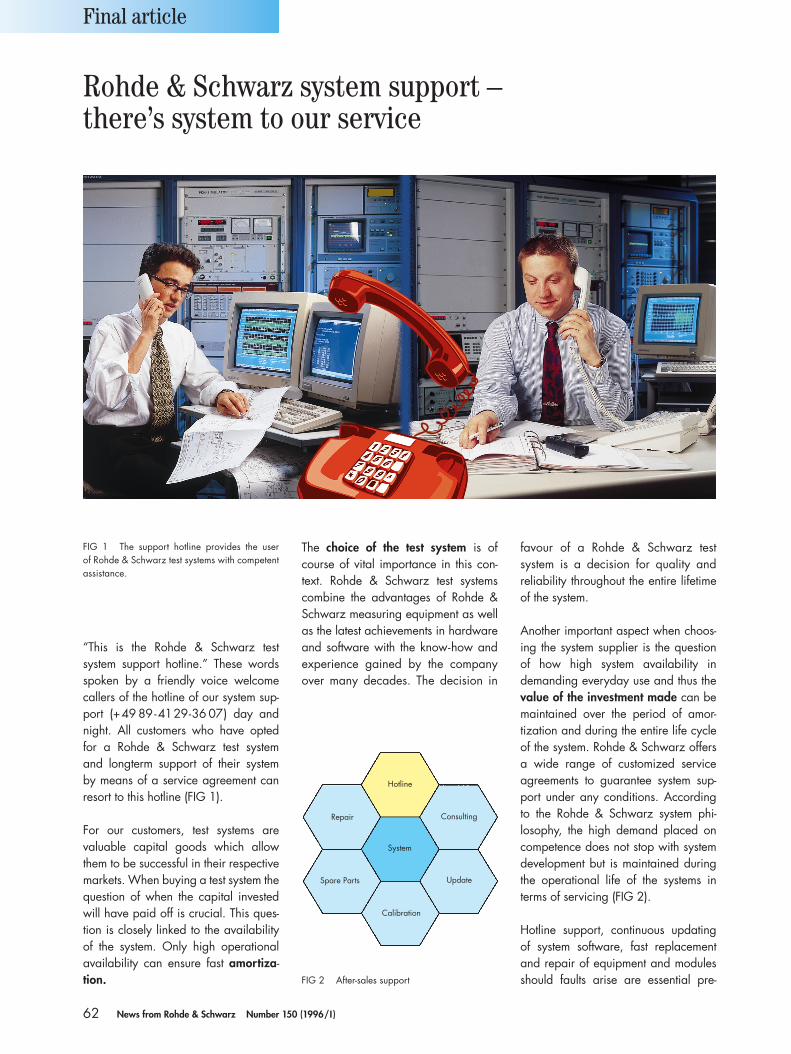
62 News from Rohde & Schwarz Number 150 (1996/I )
“This is the Rohde & Schwarz testsystem support hotline.” These wordsspoken by a friendly voice welcomecallers of the hotline of our system sup-port (+49 89-4129-36 07) day andnight. All customers who have opted for a Rohde & Schwarz test system and longterm support of their system by means of a service agreement can resort to this hotline (FIG 1).
For our customers, test systems are valuable capital goods which allowthem to be successful in their respectivemarkets. When buying a test system thequestion of when the capital investedwill have paid off is crucial. This ques-tion is closely linked to the availabilityof the system. Only high operationalavailability can ensure fast amortiza-tion.
The choice of the test system is ofcourse of vital importance in this con-text. Rohde & Schwarz test systemscombine the advantages of Rohde &Schwarz measuring equipment as wellas the latest achievements in hardwareand software with the know-how andexperience gained by the companyover many decades. The decision in
favour of a Rohde & Schwarz testsystem is a decision for quality and reliability throughout the entire lifetimeof the system.
Another important aspect when choos-ing the system supplier is the questionof how high system availability in demanding everyday use and thus thevalue of the investment made can bemaintained over the period of amor-tization and during the entire life cycleof the system. Rohde & Schwarz offersa wide range of customized serviceagreements to guarantee system sup-port under any conditions. Accordingto the Rohde & Schwarz system phi-losophy, the high demand placed on competence does not stop with system development but is maintained duringthe operational life of the systems interms of servicing (FIG 2).
Hotline support, continuous updating of system software, fast replacementand repair of equipment and modulesshould faults arise are essential pre-
Final article
FIG 1 The support hotline provides the user of Rohde & Schwarz test systems with competentassistance.
Rohde & Schwarz system support – there’s system to our service
FIG 2 After-sales support
System
Hotline
Consulting
Update
Calibration
Spare Parts
Repair
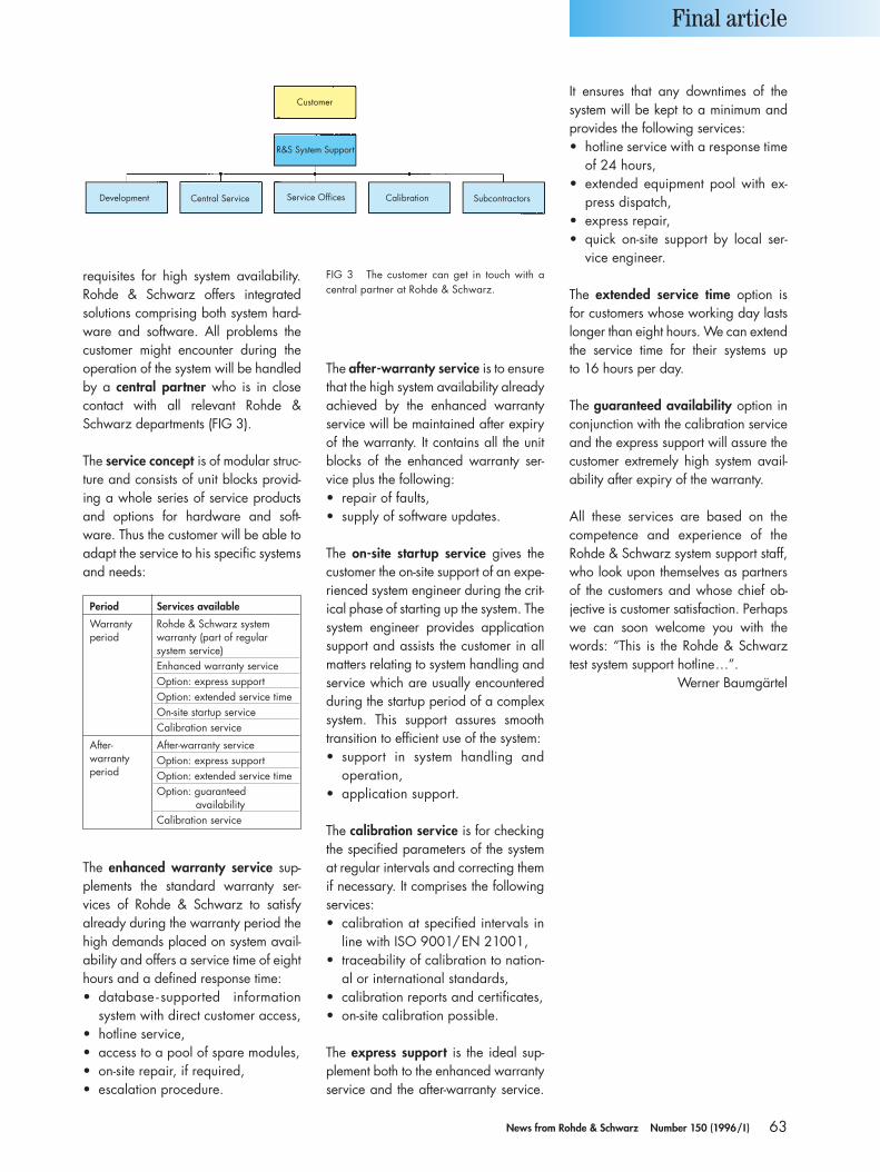
63News from Rohde & Schwarz Number 150 (1996/I )
requisites for high system availability.Rohde & Schwarz offers integrated solutions comprising both system hard-ware and software. All problems thecustomer might encounter during theoperation of the system will be handledby a central partner who is in closecontact with all relevant Rohde &Schwarz departments (FIG 3).
The service concept is of modular struc-ture and consists of unit blocks provid-ing a whole series of service productsand options for hardware and soft-ware. Thus the customer will be able toadapt the service to his specific systemsand needs:
The after-warranty service is to ensurethat the high system availability alreadyachieved by the enhanced warrantyservice will be maintained after expiryof the warranty. It contains all the unitblocks of the enhanced warranty ser-vice plus the following:• repair of faults,• supply of software updates.
The on-site startup service gives thecustomer the on-site support of an expe-rienced system engineer during the crit-ical phase of starting up the system. Thesystem engineer provides applicationsupport and assists the customer in allmatters relating to system handling andservice which are usually encounteredduring the startup period of a complexsystem. This support assures smoothtransition to efficient use of the system:• support in system handling and
operation,• application support.
The calibration service is for checkingthe specified parameters of the systemat regular intervals and correcting themif necessary. It comprises the followingservices:• calibration at specified intervals in
line with ISO 9001/EN 21001,• traceability of calibration to nation-
al or international standards,• calibration reports and certificates,• on-site calibration possible.
The express support is the ideal sup-plement both to the enhanced warrantyservice and the after-warranty service.
It ensures that any downtimes of thesystem will be kept to a minimum andprovides the following services:• hotline service with a response time
of 24 hours,• extended equipment pool with ex-
press dispatch,• express repair,• quick on-site support by local ser-
vice engineer.
The extended service time option isfor customers whose working day lastslonger than eight hours. We can extendthe service time for their systems up to 16 hours per day.
The guaranteed availability option inconjunction with the calibration serviceand the express support will assure thecustomer extremely high system avail-ability after expiry of the warranty.
All these services are based on the competence and experience of the Rohde & Schwarz system support staff,who look upon themselves as partnersof the customers and whose chief ob-jective is customer satisfaction. Perhapswe can soon welcome you with thewords: “This is the Rohde & Schwarztest system support hotline…”.
Werner Baumgärtel
Final article
FIG 3 The customer can get in touch with acentral partner at Rohde & Schwarz.
Period Services available
Warranty Rohde & Schwarz system period warranty (part of regular
system service)Enhanced warranty serviceOption: express supportOption: extended service timeOn-site startup serviceCalibration service
After- After-warranty servicewarranty Option: express supportperiod Option: extended service time
Option: guaranteedavailability
Calibration service
Customer
R&S System Support
Service Offices Calibration SubcontractorsCentral ServiceDevelopment
The enhanced warranty service sup-plements the standard warranty ser-vices of Rohde & Schwarz to satisfy already during the warranty period thehigh demands placed on system avail-ability and offers a service time of eighthours and a defined response time:• database - supported information
system with direct customer access,• hotline service,• access to a pool of spare modules,• on-site repair, if required,• escalation procedure.

New
s fro
m R
ohde
& S
chw
arz
150
· PD
757
.166
0.21
ROHDE& SCHWARZ GmbH & Co. KG · Mühldorfstraße 15 · D-81671 MünchenP. O. B. 8014 69 · D-81614 München · Tel. (+49 89) 41 29-0 · Fax (+49 89) 41 29-21 64