Newport User Commands User Commands ... Note: All commands work in an ASCII-based command and...
32
Page 1 of 32 Newport User Commands Revision History 02 24-Apr-2017 Added section Device Communication Details 01 10-May-2016 Initial Revision Introduction This document is an updated and detailed description of the various commands that are used for remote control of the new line of Newport meters (843-R-USB, 1919-R, and 841-PE-USB). For each command, we list which devices support the command as well as providing examples when necessary and listing limitations, as applicable. Note: All commands work in an ASCII-based command and response protocol. As such, data delivery rates will not be as high as when working with the standard data streaming methods provided by the COM object. Therefore, for top performance, we recommend fully embracing working with the COM object. However, if there is a need to support legacy code, or RS232 communication, this is here for you. 1919-R In addition to USB, the 1919-R device is equipped with RS232 communication capabilities.
Transcript of Newport User Commands User Commands ... Note: All commands work in an ASCII-based command and...
Page 1 of 32
Newport User Commands
Revision History
02 24-Apr-2017 Added section Device Communication Details
01 10-May-2016 Initial Revision
Introduction This document is an updated and detailed description of the various commands that are used for remote control of the new line of Newport meters (843-R-USB, 1919-R, and 841-PE-USB). For each command, we list which devices support the command as well as providing examples when necessary and listing limitations, as applicable. Note: All commands work in an ASCII-based command and response protocol. As such, data delivery rates will not be as high as when working with the standard data streaming methods provided by the COM object. Therefore, for top performance, we recommend fully embracing working with the COM object. However, if there is a need to support legacy code, or RS232 communication, this is here for you.
1919-R In addition to USB, the 1919-R device is equipped with RS232 communication capabilities.

Page 2 of 32
User Commands This section describes the commands available to control the Newport devices. It is divided into 3 sections.
1) Command Summary. Table listing all available commands. 2) Basic Commands. These commands query and set the measurement
configuration of the sensor and the device. 3) Advanced Commands. Commands that change calibration factors of the
sensors and instrument. Use of these commands will change the results of measurements and should be used only after careful consideration.
Commands are sent to the device by calling the Write method. Responses are received by calling the Read method. Note: Devices expect a command before sending a response. The user must call the Write method before waiting for a response by calling the Read method.
Device Communication Details
1) All commands and responses are ASCII strings. 2) All commands are two characters, followed by parameters (when applicable). 3) All commands are prefixed by a “$” (Hex 0x24) and suffixed by a <LF> (Hex
0x0A). 4) Response to successful command starts with a “*” (Hex 0x2A) and ends with
a <LF>. 5) Response to an invalid commands starts with a “?” (Hex 0x3F). These codes
are passed back to the user (as part of the string returned by the Read method) to allow the user to flag errors and perform application dependent error processing.
Note: The COM Object Write method for communication appends and removes the flags at the beginning and end of the ASCII strings. The above listing is for 1919-R users that wish to communicate via RS232.

Page 3 of 32
Command Summary The following table contains a listing of all commands available with Newport devices.
Command Meaning
AQ Average Query
AR All Ranges
AW All Wavelengths
BT BeamTrack
CQ Calibration Query
DQ Diffuser Query
EE Exposure Energy
EF Energy Flag
ER Energy Ready
ET Energy Threshold
FB Force BeamTrack
FE Force Energy
FP Force Power
FQ Filter Query
FS Force Screen
FX Force eXposure
GU Get range in Use
HC Head Configuration
HI Head Information
HT Head Type
IC Instrument Configuration
II Instrument Information
MA MAins
MF Maximum Frequency
MM Measurement Mode
PL Pulse Length
RE REset
RN Read range Now
RQ Response Query
SE Send Energy
SF Send Frequency
SI Send unIts
SK Simulate Key-press
SP Send Power
SX Send maX
UT User Threshold
VE VErsion
WD Wavelength adD
WE Wavelength Erase
WI Wavelength Index
WL WaveLength
WN Write range Now
ZA Zero Abort
ZE Zero
ZQ Zero Query
ZS Zero Save

Page 4 of 32
Basic Commands
Command: Average Query Supported on the following meters:
843-R-USB 1919-R 841-PE-USB
Syntax AQ <average-setting>
Description Query and set the average setting of the sensor. Returns index of presently active Average setting as well as literal description of set of all available Average settings. If an unsupported index, is specified, will prefix a '?' to the response.
Values for <average-setting> (if not set, default to 0)
0: Query device for present average setting.
1: Configure sensor for first setting (“NONE”)
2: Configure sensor for second setting.
Etc
Example Example. 919E-10-35-250 set to average over one second 1) User sent “AQ”. Device returns “* 3 NONE 0.5sec
1sec 3sec 10sec 30sec” 2) User sent “AQ 4”. Device returns “* 4 NONE 0.5sec
1sec 3sec 10sec 30sec”. Sensor is now averaging over 3 seconds
3) User sent “AQ 9”. Device returns “? 4 NONE 0.5sec 1sec 3sec 10sec 30sec”. Sensor is still averaging over 3 seconds
Limitations Thermopile sensors do not have an averaging option when measuring energy. If the command is sent when in energy mode, the instrument will return an error string
See Also Command Summary
Page 5 of 32
Command: All Ranges Supported on the following meters:
843-R-USB 1919-R 841-PE-USB
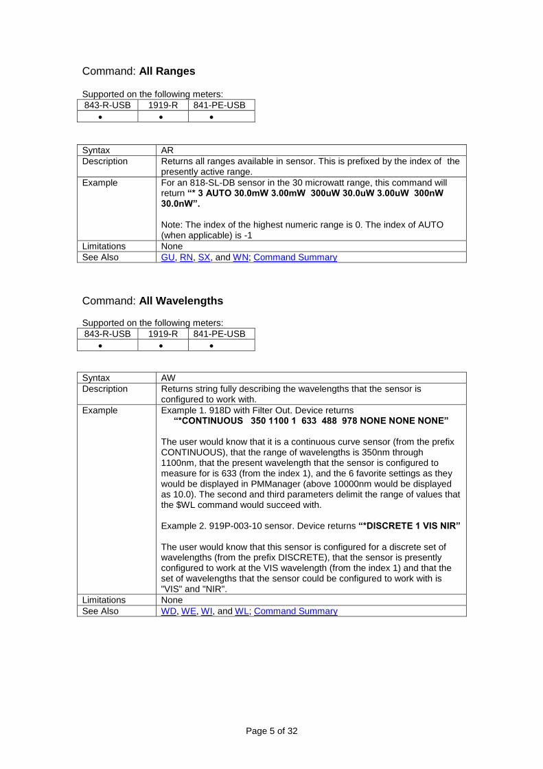
Syntax AR
Description Returns all ranges available in sensor. This is prefixed by the index of the presently active range.
Example For an 818-SL-DB sensor in the 30 microwatt range, this command will return “* 3 AUTO 30.0mW 3.00mW 300uW 30.0uW 3.00uW 300nW 30.0nW”. Note: The index of the highest numeric range is 0. The index of AUTO (when applicable) is -1
Limitations None
See Also GU, RN, SX, and WN; Command Summary
Command: All Wavelengths Supported on the following meters:
843-R-USB 1919-R 841-PE-USB
Syntax AW
Description Returns string fully describing the wavelengths that the sensor is configured to work with.
Example Example 1. 918D with Filter Out. Device returns “*CONTINUOUS 350 1100 1 633 488 978 NONE NONE NONE”
The user would know that it is a continuous curve sensor (from the prefix CONTINUOUS), that the range of wavelengths is 350nm through 1100nm, that the present wavelength that the sensor is configured to measure for is 633 (from the index 1), and the 6 favorite settings as they would be displayed in PMManager (above 10000nm would be displayed as 10.0). The second and third parameters delimit the range of values that the $WL command would succeed with. Example 2. 919P-003-10 sensor. Device returns “*DISCRETE 1 VIS NIR” The user would know that this sensor is configured for a discrete set of wavelengths (from the prefix DISCRETE), that the sensor is presently configured to work at the VIS wavelength (from the index 1) and that the set of wavelengths that the sensor could be configured to work with is "VIS" and "NIR".
Limitations None
See Also WD, WE, WI, and WL; Command Summary

Page 6 of 32
Command: BeamTrack Supported on the following meters:
843-R-USB 1919-R 841-PE-USB
Syntax BT
Description Query device for latest PEPS sensor position and size measurements. Response Format: "F" <Errors> "X" <X> "Y" <Y> "S" Size. Where F is followed by Hex map of error codes X is followed by the location of the laser spot on the X-axis in mm Y is followed by the location of the laser spot on the Y-axis in mm S is followed by the size of the laser beam in mm The following is the listing of possible error codes. Other codes may be returned by the sensor but can be ignored; they are either meant as diagnostic information for Newport personnel or are reserved for future use. 0x00001000: Position not measured (sensor can't measure position) 0x00002000: Signal too low (signal is just noise, not a meaningful measurement) 0x00004000: Position Measurement out of range (laser beam hit detector too far off center) 0x00008000: General Position Measurement Error
Example Example: * F 00000000 X -1.50 Y -0.9 S 6.50 There were no errors, the spot size is 6.5mm and is found at the coordinates (-1.5, -0.9)
Limitations For PEPS sensors only.
See Also Command Summary

Page 7 of 32
Command: Diffuser Query Supported on the following meters:
843-R-USB 1919-R 841-PE-USB
Syntax DQ <diffuser-setting>
Description Query and set the diffuser setting of the sensor. Values for <diffuser-setting> (if parameter isn’t set, default to 0)
0: Query meter for present Diffuser Mode
1: Configure sensor for Diffuser Out mode
2: Configure sensor for Diffuser In mode
Example Example 1. A 919E-0.1-12-25K sensor. 1) User sent “DQ”. Device returns “*1 N/A”. There is only 1
setting (that the command is not applicable). Example 2. 919E-10-35-250.
1) User sent “DQ”. Device returns “*1 OUT IN”. Sensor is in Diffuser Out mode.
2) User sent “DQ 2”. Device returns “* 2 OUT IN”. Sensor is now in Diffuser In mode.
3) User sent “DQ 3”. Device returns “? 2 OUT IN”. Request is invalid and sensor remains in Diffuser In mode.
Limitations For Pyroelectric sensor only
See Also HC; Command Summary
Command: Exposure Energy Supported on the following meters:
843-R-USB 1919-R 841-PE-USB
Syntax EE
Description Instructs device to report up do date exposure measurement, number of pulses, and time elapsed (in tenths of seconds).
Example Example 1. Pyroelectric sensor in exposure mode. Device returns “* 1.064E-1 2773 124” Total exposure is 106.4mJ, 2773 pulses have been measured, and 12.4 seconds have elapsed since the start of exposure measurement. Example 2. Pyroelectric sensor in energy mode. Device returns “?HEAD NOT MEASURING EXPOSURE” Example 3. Pyroelectric sensor in power mode. Device returns “HEAD NOT MEASURING ENERGY”
Limitations For Pyroelectric sensors only
See Also FX; Command Summary
Page 8 of 32
Command: Energy Flag Supported on the following meters:
843-R-USB 1919-R 841-PE-USB
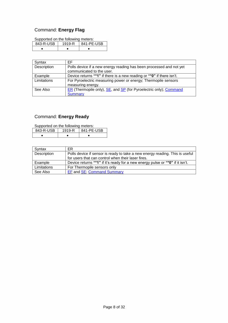
Syntax EF
Description Polls device if a new energy reading has been processed and not yet communicated to the user.
Example Device returns “*1” if there is a new reading or “*0” if there isn’t.
Limitations For Pyroelectric measuring power or energy; Thermopile sensors measuring energy.
See Also ER (Thermopile only), SE, and SP (for Pyroelectric only); Command Summary
Command: Energy Ready Supported on the following meters:
843-R-USB 1919-R 841-PE-USB
Syntax ER
Description Polls device if sensor is ready to take a new energy reading. This is useful for users that can control when their laser fires.
Example Device returns “*1” if it’s ready for a new energy pulse or “*0” if it isn’t.
Limitations For Thermopile sensors only
See Also EF and SE; Command Summary

Page 9 of 32
Command: Energy Threshold Supported on the following meters:
843-R-USB 1919-R 841-PE-USB
Syntax ET <threshold>
Description Query and set the threshold setting of the sensor. Values for <threshold> (if not set, default to 0)
0: Query sensor for present threshold setting.
1: Configure sensor to work with LOW threshold.
2: Configure sensor to work with MEDIUM threshold.
3: Configure sensor to work with HIGH threshold.
Example Example. 919P-030-18 sensor. 1) User sent “ET”. Device returns “*2 LOW MEDIUM
HIGH”. The sensor is in MEDIUM threshold mode. 2) User sent “ET 4”. Device returns “?1 LOW MEDIUM
HIGH”. Trigger level is invalid and sensor remains in LOW threshold mode.
3) User sent “ET 3”. Device returns “*3 LOW MEDIUM HIGH”. Sensor has been configured to work in HIGH threshold mode.
Limitations For Thermopile sensors only
See Also HC, UT; Command Summary
Command: Force BeamTrack Supported on the following meters:
843-R-USB 1919-R 841-PE-USB
Syntax FB
Description Puts instrument into Position Measurement mode. Device returns “*” if successful and “?HEAD CANNOT MEASURE BEAMTRACK” if not.
Example User sent “FB”. Device returns “*”. Sensor is now measuring Position.
Limitations For PEPS series of sensors only.
See Also FE, FP, FX, HC, HI, MM, and SE; Command Summary
Command: Force Energy Supported on the following meters:
843-R-USB 1919-R 841-PE-USB
Syntax FE
Description Puts instrument into Energy Measurement mode. Device returns “*” if successful and “?HEAD CANNOT MEASURE ENERGY” if not.
Example User sent “FE”. Device returns “*”. Sensor is now measuring Energy.
Limitations For Thermopile and Pyroelectric sensors.
See Also FB, FP, FX, HC, HI, MM, and SE; Command Summary
Page 10 of 32
Command: Force Power Supported on the following meters:
843-R-USB 1919-R 841-PE-USB
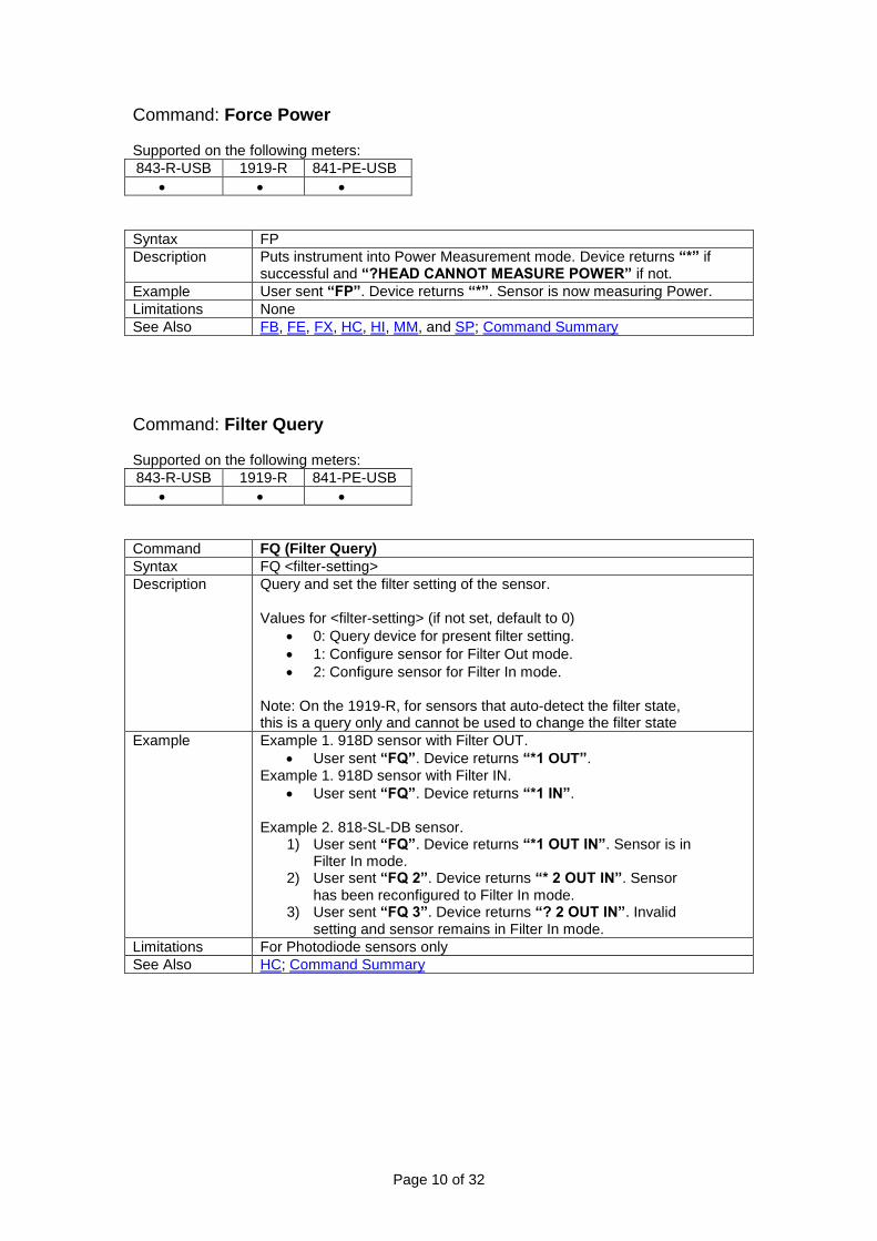
Syntax FP
Description Puts instrument into Power Measurement mode. Device returns “*” if successful and “?HEAD CANNOT MEASURE POWER” if not.
Example User sent “FP”. Device returns “*”. Sensor is now measuring Power.
Limitations None
See Also FB, FE, FX, HC, HI, MM, and SP; Command Summary
Command: Filter Query Supported on the following meters:
843-R-USB 1919-R 841-PE-USB
Command FQ (Filter Query)
Syntax FQ <filter-setting>
Description Query and set the filter setting of the sensor. Values for <filter-setting> (if not set, default to 0)
0: Query device for present filter setting.
1: Configure sensor for Filter Out mode.
2: Configure sensor for Filter In mode. Note: On the 1919-R, for sensors that auto-detect the filter state, this is a query only and cannot be used to change the filter state
Example Example 1. 918D sensor with Filter OUT.
User sent “FQ”. Device returns “*1 OUT”. Example 1. 918D sensor with Filter IN.
User sent “FQ”. Device returns “*1 IN”. Example 2. 818-SL-DB sensor.
1) User sent “FQ”. Device returns “*1 OUT IN”. Sensor is in Filter In mode.
2) User sent “FQ 2”. Device returns “* 2 OUT IN”. Sensor has been reconfigured to Filter In mode.
3) User sent “FQ 3”. Device returns “? 2 OUT IN”. Invalid setting and sensor remains in Filter In mode.
Limitations For Photodiode sensors only
See Also HC; Command Summary

Page 11 of 32
Command: Force Screen Supported on the following meters:
843-R-USB 1919-R 841-PE-USB
Syntax Force Screen <screen-setting>
Description Force the instrument into one of the screens Values for <screen-setting>
0: Force to power measurement.
1: Force to energy measurement.
2: Force to non-measurement screen
3: Force to no sensor connected screen
5: Force to Position screen (BeamTrack sensors only)
Example Example 1. 919P-003-10. 1) User sent “FS 1”. Now measuring power 2) User sent “FS 2”. Now measuring energy
Example 2. 918D sensor.
3) User sent “FS 1”. Now measuring power 4) User sent “FS 2”. Device responds with error code
because sensor cannot be used for measuring energy
Limitations None
See Also FB, FE, FP, HC, MM: Command Summary
Command: Force Exposure Supported on the following meters:
843-R-USB 1919-R 841-PE-USB
Syntax FX
Description Puts instrument into exposure measurement mode. Device returns “*” upon success.
Example User sent “FX”. Device returns “*”. Sensor is now measuring Exposure.
Limitations For Pyroelectric sensors only
See Also EE, FE, FP, MM, and SE; Command Summary

Page 12 of 32
Command: Get range in Use Supported on the following meters:
843-R-USB 1919-R 841-PE-USB
Syntax GU
Description When in autoranging, returns presently active numeric range.
Example 918D with Filter Out in autoranging. The latest readings have been about 2mW. Device returns “*1”.
Limitations None
See Also AR, RN, SX, and WN; Command Summary
Command: Head Configuration Supported on the following meters:
843-R-USB 1919-R 841-PE-USB
Syntax HC <configuration>
Description Save selected Sensor Configuration Settings. Values for <configuration>
‘S’: startup settings (Filter Setting, Energy Range, Diffuser setting, etc.).
‘C’: Calibration settings.
‘R’: Response settings. Device returns “*SAVED” on success, “*UNCHANGED” if nothing needed to be updated, or “?FAILED” if not successful.
Example None
Limitations R is for Thermopile sensors only
See Also CQ, DQ, ET, FE, FP, FQ, PL, RQ, WD, WE, WI, WL, WN, Command Summary

Page 13 of 32
Command: Head Information Supported on the following meters:
843-R-USB 1919-R 841-PE-USB
Syntax HI
Description Returns type, serial number, name, and measurement abilities of sensor. Measurement abilities are reported as an 8 byte hexadecimal code where Bit 0 is lit if sensor can measure power. Bit 1 is lit if sensor can measure energy. Bit 31 is lit if sensor can measure frequency. All other bits are reserved and are not guaranteed to be 0 or 1.
Example Example 1. 919P-003-10 sensor. Device returns “* TH 12345 919P-003-10 00000183”. The user knows that this is a Thermopile sensor (TH), its serial number (12345) and name (919P-003-10), and that it can be used to measure power or energy (bits 0 and 1 are lit). Example 2. 919E-0.1-12-25K sensor. Device returns “* PY 22323 919E-0.1-12 80000003”. The user knows that this is a Pyroelectric sensor (PY), the serial number and name, and that it can measure power, energy, and frequency
Limitations None
See Also FE, FP, HT, and II; CommandSummary
Command: Head Type Supported on the following meters:
843-R-USB 1919-R 841-PE-USB
Syntax HT
Description Returns more specific sensor type than the HI command Return Codes:
BT: BeamTrack
CP: Pyroelectric
SI : Photodiode
TH : Thermopile
XX : No sensor connected
Example 919P-003-10 sensor. Device returns “*TH” 919E-0.1-12-25K sensor. Device returns “*CP”
Limitations None
See Also FE, FP, HI, and II; CommandSummary
Page 14 of 32
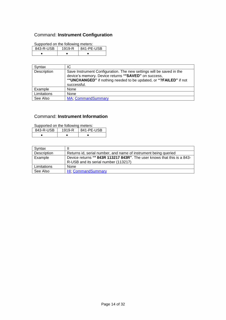
Command: Instrument Configuration Supported on the following meters:
843-R-USB 1919-R 841-PE-USB
Syntax IC
Description Save Instrument Configuration. The new settings will be saved in the device’s memory. Device returns “*SAVED” on success, “*UNCHANGED” if nothing needed to be updated, or “?FAILED” if not successful.
Example None
Limitations None
See Also MA; CommandSummary
Command: Instrument Information Supported on the following meters:
843-R-USB 1919-R 841-PE-USB
Syntax II
Description Returns id, serial number, and name of instrument being queried
Example Device returns “* 843R 113217 843R”. The user knows that this is a 843-R-USB and its serial number (113217)
Limitations None
See Also HI; CommandSummary

Page 15 of 32
Command: MAins Supported on the following meters:
843-R-USB 1919-R 841-PE-USB
Syntax MA <line-frequency>
Description Query and set the line-frequency setting of the instrument. Values for <line-frequency> (if not set, default is 0)
0: Query meter for present setting.
1: Configure meter to work with mains of 50Hz (European standard).
2: Configure meter to work with mains of 60Hz (North American and Japanese standard).
Response: String containing index of presently active mains setting as well as literal description of both mains settings. If Remote User specified an unsupported index, will prefix a '?' to the response. Note: Factory default for devices is 50Hz
Example Example 1. User sent “MA”. Device returns “* 2 50Hz 60Hz”. The User knows that the device is configured to work with a line frequency of 60Hz. Example 2. European customer wants to set the device to correct line frequency and sends “MA 1”. Device returns “* 1 50Hz 60Hz”
Limitations None
See Also IC; CommandSummary
Command: Maximum Frequency Supported on the following meters:
843-R-USB 1919-R 841-PE-USB
Command MF (Maximum Frequency)
Syntax MF
Description Queries the device for maximum pulse frequency at which the sensor can sample the laser for energy measurements.
Example Example 1. 919E-10-24-10K set to 1μS pulse width. Device returns “*10000”. The sensor can sample pulses of a laser whose frequency is 10kHz. Example 2. 919E-10-24-10K set to 5mS pulse width. Device returns “*100”. The sensor can sample pulses of a laser whose frequency is 100 Hertz.
Limitations For Pyroelectric and Photodiode energy sensors only
See Also HI, PL, and SF; CommandSummary

Page 16 of 32
Command: Measurement Mode Supported on the following meters:
843-R-USB 1919-R 841-PE-USB
Syntax MM <measurement-mode>
Description Set instrument to selected Measurement Mode Values for < measurement-mode >
0: Query present measurement mode
1: Passive, non-measurement mode
2: Power
3: Energy
4: Exposure (1919-R and 841-PE-USB only)
5: Power with Position (and Size) for PEPS sensors
6: Reserved for Future Use
7: Reserved for Future Use
8: Reserved for Future Use
9: Reserved for Future Use
10: Reserved for Future Use
11: Reserved for Future Use
12: Reserved for Future Use
13: Reserved for future use
14: Power from Pulse (Thermopile on 1919-R only) Device returns “*” on success, “?NOT SUPPORTED” if the sensor doesn’t support this measurement mode, or “?PARAM ERROR” if it doesn’t recognize the <measurement-mode> Note: MM is meant to supersede the FB, FE, FP, and FX commands.
Example None
Limitations As listed above
See Also FB, FE, FP, FX, HC; Command Summary
Page 17 of 32
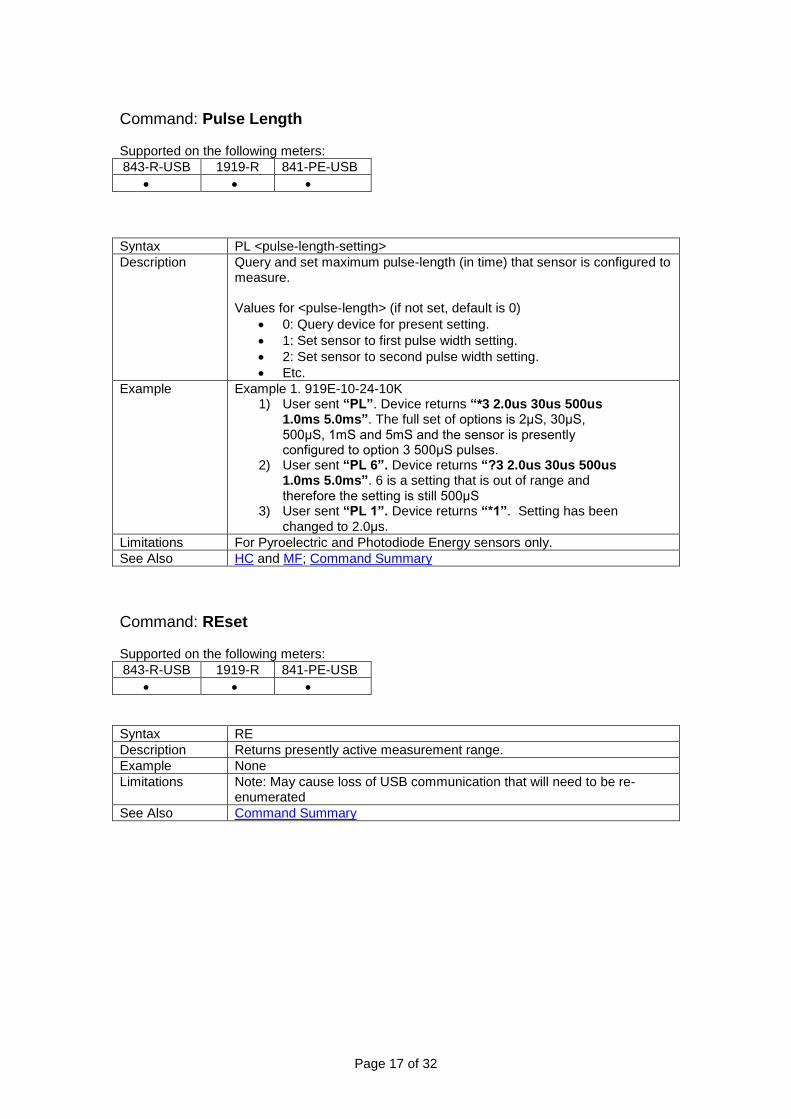
Command: Pulse Length Supported on the following meters:
843-R-USB 1919-R 841-PE-USB
Syntax PL <pulse-length-setting>
Description Query and set maximum pulse-length (in time) that sensor is configured to measure. Values for <pulse-length> (if not set, default is 0)
0: Query device for present setting.
1: Set sensor to first pulse width setting.
2: Set sensor to second pulse width setting.
Etc.
Example Example 1. 919E-10-24-10K 1) User sent “PL”. Device returns “*3 2.0us 30us 500us
1.0ms 5.0ms”. The full set of options is 2μS, 30μS, 500μS, 1mS and 5mS and the sensor is presently configured to option 3 500μS pulses.
2) User sent “PL 6”. Device returns “?3 2.0us 30us 500us 1.0ms 5.0ms”. 6 is a setting that is out of range and therefore the setting is still 500μS
3) User sent “PL 1”. Device returns “*1”. Setting has been changed to 2.0μs.
Limitations For Pyroelectric and Photodiode Energy sensors only.
See Also HC and MF; Command Summary
Command: REset Supported on the following meters:
843-R-USB 1919-R 841-PE-USB
Syntax RE
Description Returns presently active measurement range.
Example None
Limitations Note: May cause loss of USB communication that will need to be re-enumerated
See Also Command Summary

Page 18 of 32
Command: Read range Now Supported on the following meters:
843-R-USB 1919-R 841-PE-USB
Syntax RN
Description Returns presently active measurement range.
Example Example 1. 918D in autoranging. Device responds “*-1”. Example 2. 919E-10-24-10K in 2mJ range. Device responds “*4”.
Limitations
See Also AR, GU, SX, and WN; Command Summary
Command: Send Energy Supported on the following meters:
843-R-USB 1919-R 841-PE-USB
Syntax SE
Description Queries device for Energy Measurement
Example This command returns the most recent energy measurement. To verify that the device has not previously reported it to the user, this command should be used in together with the EF command. Example.
1) User sends EF command. 2) Read device response. If response is “*0” repeat step 1.
If response is “*1” continue with step 3. 3) User send SE command 4) Device responds “*1.100E-4” (110uJ)
Limitations Not for Photodiode sensors. Sensor must be measuring Energy
See Also EF, ER, FE, SF, and SP; Command Summary

Page 19 of 32
Command: Send Frequency Supported on the following meters:
843-R-USB 1919-R 841-PE-USB
Syntax SF
Description Queries device for frequency at which the laser is firing. Note: Although sensors can measure frequency up to 1000’s of Hertz, to actually measure each of those pulses, you must work with the COM object
Example Example. Device returns “*1.000E3”. The laser is firing at a frequency of 1000Hz.
Limitations For Pyroelectric Photodiode energy sensors only
See Also MF, PL, SE, and SP; Command Summary
Page 20 of 32
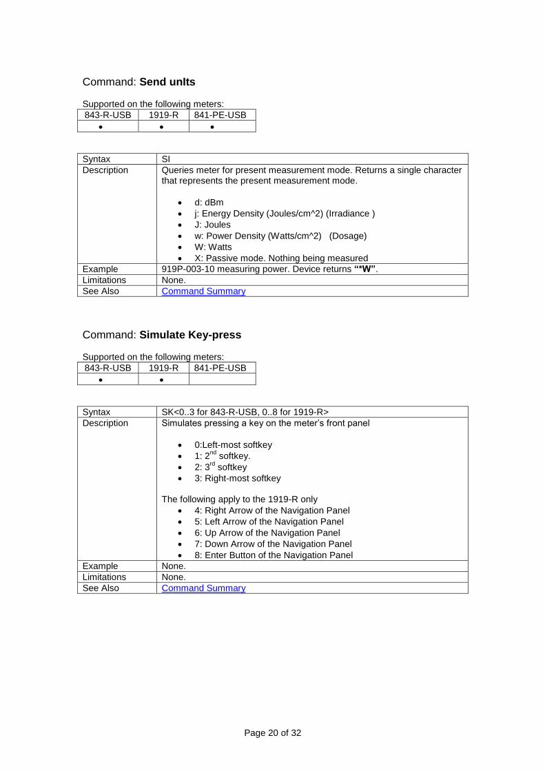
Command: Send unIts Supported on the following meters:
843-R-USB 1919-R 841-PE-USB
Syntax SI
Description Queries meter for present measurement mode. Returns a single character that represents the present measurement mode.
d: dBm
j: Energy Density (Joules/cm^2) (Irradiance )
J: Joules
w: Power Density (Watts/cm̂ 2) (Dosage)
W: Watts
X: Passive mode. Nothing being measured
Example 919P-003-10 measuring power. Device returns “*W”.
Limitations None.
See Also Command Summary
Command: Simulate Key-press Supported on the following meters:
843-R-USB 1919-R 841-PE-USB
Syntax SK<0..3 for 843-R-USB, 0..8 for 1919-R>
Description Simulates pressing a key on the meter’s front panel
0:Left-most softkey
1: 2nd
softkey.
2: 3rd
softkey
3: Right-most softkey The following apply to the 1919-R only
4: Right Arrow of the Navigation Panel
5: Left Arrow of the Navigation Panel
6: Up Arrow of the Navigation Panel
7: Down Arrow of the Navigation Panel
8: Enter Button of the Navigation Panel
Example None.
Limitations None.
See Also Command Summary
Page 21 of 32
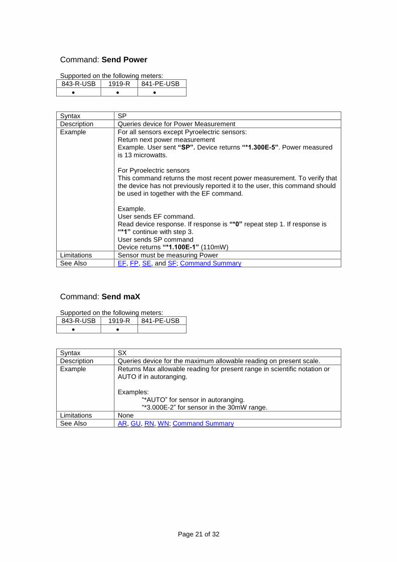
Command: Send Power Supported on the following meters:
843-R-USB 1919-R 841-PE-USB
Syntax SP
Description Queries device for Power Measurement
Example For all sensors except Pyroelectric sensors: Return next power measurement Example. User sent “SP”. Device returns “*1.300E-5”. Power measured is 13 microwatts. For Pyroelectric sensors This command returns the most recent power measurement. To verify that the device has not previously reported it to the user, this command should be used in together with the EF command. Example. User sends EF command. Read device response. If response is “*0” repeat step 1. If response is “*1” continue with step 3. User sends SP command Device returns “*1.100E-1” (110mW)
Limitations Sensor must be measuring Power
See Also EF, FP, SE, and SF; Command Summary
Command: Send maX Supported on the following meters:
843-R-USB 1919-R 841-PE-USB
Syntax SX
Description Queries device for the maximum allowable reading on present scale.
Example Returns Max allowable reading for present range in scientific notation or AUTO if in autoranging. Examples:
“*AUTO” for sensor in autoranging. “*3.000E-2” for sensor in the 30mW range.
Limitations None
See Also AR, GU, RN, WN; Command Summary

Page 22 of 32
Command: User Threshold Supported on the following meters:
843-R-USB 1919-R 841-PE-USB
Syntax UT <0..2500>
Description Queries and sets threshold for Pyroelectric and Photodiode energy sensors. This aids in screening out false triggers due that may arise due to electronic noise.
Example Examples:
“$UT”. Device returns “*300 169 2500”. Present threshold setting is 3%, minimum is 1.69%, maximum is 25%
“$UT 2000” Device returns “*2000 169 2500”. Threshold now set to 20%, minimum is 1.69%, maximum is 25%
Limitations For Pyroelectric and Photodiode energy sensors only.
See Also ET; Command Summary
Command: VErsion Supported on the following meters:
843-R-USB 1919-R 841-PE-USB
Syntax VE
Description Query device for version of embedded software
Example Version 1.33 of software is installed. The 843-R-USB returns “*EF1.33”
Limitations None
See Also Command Summary

Page 23 of 32
Command: Wavelength adD Supported on the following meters:
843-R-USB 1919-R 841-PE-USB
Syntax WD <Index> <Wavelength>
Description Add a wavelength to list of favorite wavelengths that the sensor is configured to work with. Index: Location in list of wavelengths in which to insert the wavelength selected (must between an unused value between 1 and 6 as returned by the AW command) Wavelength: New favorite wavelength (must be between the lower and upper wavelength limits as returned by the AW command)
Example 919E-0.1-12-25K with these settings as returned by the AW command “*CONTINUOUS 193 12000 4 NONE 366 532 1064 2100 10.6”
1) User sent “WD 4 248”. Device returns “?WAVELENGTH ALREADY DEFINED. USE WL COMMAND”
2) Example 2. User sent “WD 1 100”. Device returns “?WAVELENGTH OUT OF RANGE”
3) Example 3. User sent “WD 7 248”. Device returns “?INDEX NOT IN RANGE”.
4) 4. User sent “WD 1 248”. Device returns “*”.
Limitations For all sensors with a continuous spectrum
See Also AW, HC, WE, WI, and WL; Command Summary
Command: Wavelength Erase Supported on the following meters:
843-R-USB 1919-R 841-PE-USB
Syntax WE <Index>
Description Instructs device to delete from its list of favorite wavelengths the wavelength at location <Index>. Index must be between 1 and 6 and not the presently active index.
Example 919E-0.1-12-25K with these settings as returned by the AW command “*CONTINUOUS 193 12000 4 248 366 532 1064 2100 10.6”
1) User sent “WE 4”. Device returns “?CANNOT ERASE PRESENTLY ACTIVE INDEX”.
2) Example 2. User sent “WE 5”. Device returns “*”.
Limitations For all sensors with a continuous spectrum
See Also AW, HC, WD, WI, and WL; Command Summary
Page 24 of 32
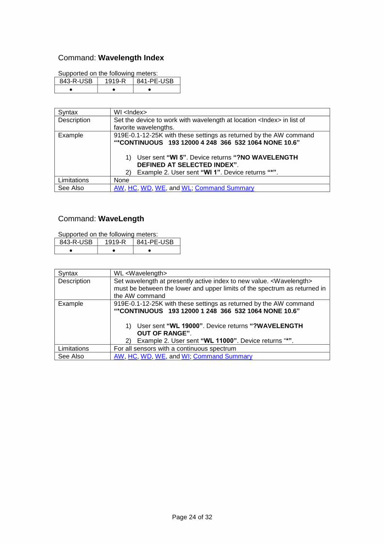
Command: Wavelength Index Supported on the following meters:
843-R-USB 1919-R 841-PE-USB
Syntax WI <Index>
Description Set the device to work with wavelength at location <Index> in list of favorite wavelengths.
Example 919E-0.1-12-25K with these settings as returned by the AW command “*CONTINUOUS 193 12000 4 248 366 532 1064 NONE 10.6”
1) User sent “WI 5”. Device returns “?NO WAVELENGTH DEFINED AT SELECTED INDEX”.
2) Example 2. User sent “WI 1”. Device returns “*”.
Limitations None
See Also AW, HC, WD, WE, and WL; Command Summary
Command: WaveLength Supported on the following meters:
843-R-USB 1919-R 841-PE-USB
Syntax WL <Wavelength>
Description Set wavelength at presently active index to new value. <Wavelength> must be between the lower and upper limits of the spectrum as returned in the AW command
Example 919E-0.1-12-25K with these settings as returned by the AW command “*CONTINUOUS 193 12000 1 248 366 532 1064 NONE 10.6”
1) User sent “WL 19000”. Device returns “?WAVELENGTH OUT OF RANGE”.
2) Example 2. User sent “WL 11000”. Device returns “*”.
Limitations For all sensors with a continuous spectrum
See Also AW, HC, WD, WE, and WI; Command Summary

Page 25 of 32
Command: Write range Now Supported on the following meters:
843-R-USB 1919-R 841-PE-USB
Syntax WN <range-setting>
Description Configure sensor to measure in a specific range Note: The index of the highest numeric range is 0. The index of AUTO (when applicable) is –1
Example To force a 918D in Filter Out mode into the 3mW range enter “WN 1”. Device returns “*”.
Limitations None
See Also AR, GU, RN, and SX; Command Summary
Page 26 of 32
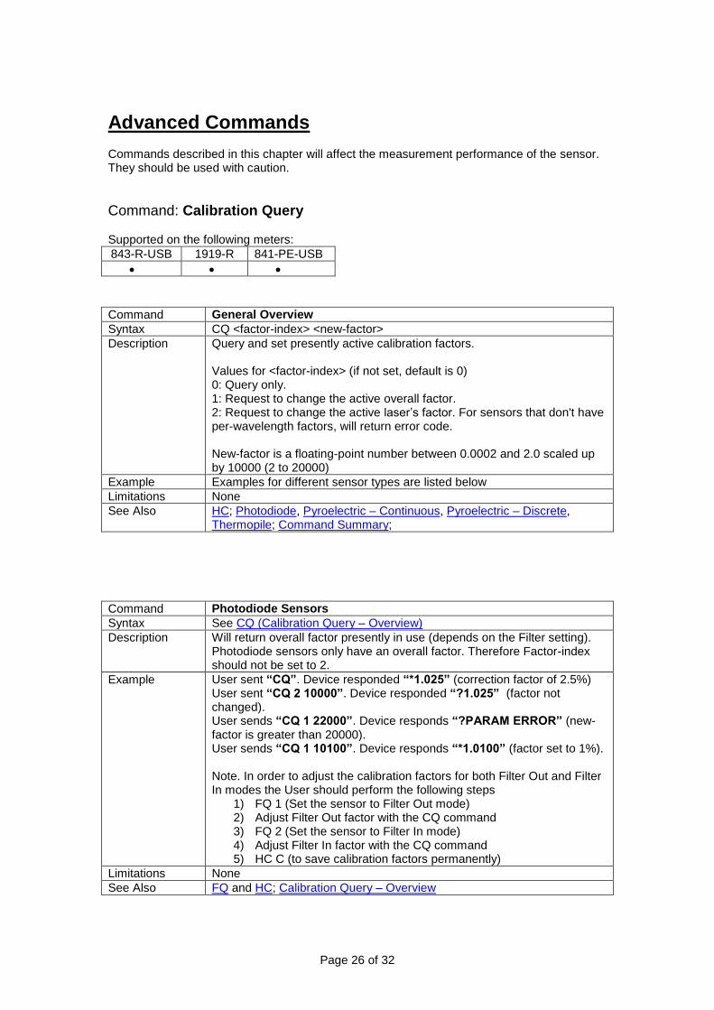
Advanced Commands Commands described in this chapter will affect the measurement performance of the sensor. They should be used with caution.
Command: Calibration Query Supported on the following meters:
843-R-USB 1919-R 841-PE-USB
Command General Overview
Syntax CQ <factor-index> <new-factor>
Description Query and set presently active calibration factors. Values for <factor-index> (if not set, default is 0) 0: Query only. 1: Request to change the active overall factor. 2: Request to change the active laser’s factor. For sensors that don't have per-wavelength factors, will return error code. New-factor is a floating-point number between 0.0002 and 2.0 scaled up by 10000 (2 to 20000)
Example Examples for different sensor types are listed below
Limitations None
See Also HC; Photodiode, Pyroelectric – Continuous, Pyroelectric – Discrete, Thermopile; Command Summary;
Command Photodiode Sensors
Syntax See CQ (Calibration Query – Overview)
Description Will return overall factor presently in use (depends on the Filter setting). Photodiode sensors only have an overall factor. Therefore Factor-index should not be set to 2.
Example User sent “CQ”. Device responded “*1.025” (correction factor of 2.5%) User sent “CQ 2 10000”. Device responded “?1.025” (factor not changed). User sends “CQ 1 22000”. Device responds “?PARAM ERROR” (new-factor is greater than 20000). User sends “CQ 1 10100”. Device responds “*1.0100” (factor set to 1%). Note. In order to adjust the calibration factors for both Filter Out and Filter In modes the User should perform the following steps
1) FQ 1 (Set the sensor to Filter Out mode) 2) Adjust Filter Out factor with the CQ command 3) FQ 2 (Set the sensor to Filter In mode) 4) Adjust Filter In factor with the CQ command 5) HC C (to save calibration factors permanently)
Limitations None
See Also FQ and HC; Calibration Query – Overview

Page 27 of 32
Command Thermopile Sensors
Syntax See CQ (Calibration Query – Overview)
Description CQ returns 4 values 1) User Power or Energy factor (depending on measurement
mode). This factor can be updated by “CQ 1 <value>”. It affects measurements with any laser.
2) User Laser factor. This factor can be updated by “CQ 2 <value>”. It affects measurement with the presently active laser only
3) Overall Laser factor. This is the factor that the Device uses for the present Laser in use. It is affected by the User Laser Factor and by an Newport calibration factor for this wavelength that cannot be adjusted by the User
4) Overall Sensitivity. This is a composite of the User Power factor, the Laser factors in use, and an Newport overall sensitivity factor that cannot be adjusted by the User. Note that changes in the Power Factor affect this field for all Lasers. Changes in the User Laser Factor affect this field only for the present laser in use.
Example 1) User sent “AW”. Device responded “*DISCRETE 1 CO2 YAG VIS”. Presently active laser is CO2
2) User sent “SI”. Device responded “*W”. Sensor is in power mode.
3) User sent “CQ”. Device responded “*1.0000 1.0000 1.0000 2.5926E-8”. These are the factors for CO2 laser in Power Mode.
4) User sent “CQ 1 11000”. Device responded “*1.1000 1.0000 1.0000 2.3569E-8”. Note the change in fields 1 and 4.
5) User sent “CQ 2 11000”. Device responded “*1.1000 1.1000 1.1000 2.1426E-8”. Note the change in fields 2, 3, and 4
6) User sent “WI 2”. Device responded “*”. Presently active laser is now YAG.
7) User sent “CQ”. Device responded “*1.1000 1.0000 1.0950 2.1524E-8”. Fields 2, 3, and 4 were replaced by values for YAG laser
8) User sent “CQ 2 9000”. Device responded “*1.1000 0.8999 0.9853 2.3919E-8”. Note change in fields 2, 3, and 4
9) User sent “WI 1”. Device responded “*”. Presently active laser is now CO2.
10) User sent “CQ”. Device responded “*1.1000 1.1000 1.1000 2.1426E-8”. Notice that the values are the same as in step 5. The laser specific changes of step 8 have no affect on a different laser.
11) User sent “FE”. Device responded “*”. Sensor is in energy mode
12) User sent “CQ”. Device responded “*1.0000 1.1000 1.1000 2.1426E-8”. Field 1 is the energy factor. It has no affect on field 4.
Limitations None
See Also AW, FE, FP, HC, and WI; Calibration Query – Overview

Page 28 of 32
Command Pyroelectric Sensors – Continuous
Syntax See CQ (Calibration Query – Overview)
Description Will return overall factor presently in use (depends on the Pulse Width setting). These Pyroelectric sensors only have an overall factor. Therefore Factor-index should not be set to 2.
Example User sends “CQ”. Device responds “*1.025” (correction factor of 2.5%) User sends “CQ 2 10000”. Device responds “?1.025” (factor not changed) User sends “CQ 1 22000”. Device responds “?PARAM ERROR” (new-factor is greater than 20000) User sends “CQ 1 10100”. Device responds “*1.0100” (factor set to 1%) Note. In order to adjust the calibration factors for all pulse widths, use CQ in conjunction with the PL command.
Limitations None
See Also PL and HC; Calibration Query – Overview
Page 29 of 32
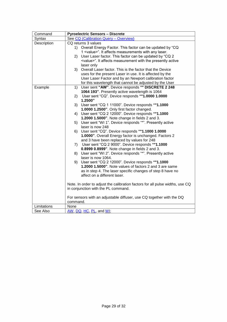
Command Pyroelectric Sensors – Discrete
Syntax See CQ (Calibration Query – Overview)
Description CQ returns 3 values 1) Overall Energy Factor. This factor can be updated by “CQ
1 <value>”. It affects measurements with any laser. 2) User Laser factor. This factor can be updated by “CQ 2
<value>”. It affects measurement with the presently active laser only
3) Overall Laser factor. This is the factor that the Device uses for the present Laser in use. It is affected by the User Laser Factor and by an Newport calibration factor for this wavelength that cannot be adjusted by the User
Example 1) User sent “AW”. Device responds “* DISCRETE 2 248 1064 193”. Presently active wavelength is 1064
2) User sent “CQ”. Device responds “*1.0000 1.0000 1.2500”
3) User sent “CQ 1 11000”. Device responds “*1.1000 1.0000 1.2500”. Only first factor changed.
4) User sent “CQ 2 12000”. Device responds “*1.1000 1.2000 1.5000”. Note change in fields 2 and 3.
5) User sent “WI 1”. Device responds “*”. Presently active laser is now 248
6) User sent “CQ”. Device responds “*1.1000 1.0000 1.0000”. Overall Energy factor is unchanged. Factors 2 and 3 have been replaced by values for 248
7) User sent “CQ 2 9000”. Device responds “*1.1000 0.8999 0.8999”. Note change in fields 2 and 3.
8) User sent “WI 2”. Device responds “*”. Presently active laser is now 1064.
9) User sent “CQ 2 12000”. Device responds “*1.1000 1.2000 1.5000”. Note values of factors 2 and 3 are same as in step 4. The laser specific changes of step 8 have no affect on a different laser.
Note. In order to adjust the calibration factors for all pulse widths, use CQ in conjunction with the PL command. For sensors with an adjustable diffuser, use CQ together with the DQ command.
Limitations None
See Also AW, DQ, HC, PL, and WI;

Page 30 of 32
Command: Response Query Supported on the following meters:
843-R-USB 1919-R 841-PE-USB
Syntax RQ <response-factor>
Description Query and set the User adjustable response time factor. Response-factor is a floating-point number between 0.0002 and 2.0 scaled up by 10000 (2 to 20000)
Example User sent “RQ”. Device responds “*1.000” User sends “RQ 22000”. Device responds “?PARAM ERROR” (Response-factor is greater than 20000). User sends “RQ 10100”. Device responds “*1.0100”
Limitations For Thermopile sensors only
See Also CQ and HC; Calibration Query – Overview; Command Summary;
Command: Zero Abort Supported on the following meters:
843-R-USB 1919-R 841-PE-USB
Syntax ZA
Description Aborts request to zero the device’s measurement circuitry. Device returns status of the zeroing process. “*ZEROING NOT STARTED”. If ZA was sent before the ZE command. “*ZEROING ABORTED”. If ZA was sent before zeroing was completed. “*ZEROING COMPLETED”. If ZA was sent after zeroing was completed.
Example Example. User sent “ZE” followed by the “ZA” command. Device returned “*ZEROING ABORTED”.
Limitations None
See Also ZE, ZQ, and ZS; Command Summary

Page 31 of 32
Command: ZEro Supported on the following meters:
843-R-USB 1919-R 841-PE-USB
Syntax ZE
Description Analog components occasionally “drift” thereby introducing small errors in the meter’s measurement circuitry. This command measures that drift and subtracts it from measurements. We suggest zeroing the device once in two months.
Example Example 1. User sent “ZE”. Device responded “*”. Example 2. User sent “ZE” before previous zeroing request terminated. Device responded “?ZEROING IN PROGRESS”. Note. There are three different types of zeroings.
1) High Impedance: With no sensor attached or with a Photodiode sensor attached.
2) Low Impedance: With a Thermopile sensor attached. For these sensors, the User should first perform a Low Impedance zero, save the result, and then perform a High Impedance zero.
3) Fast Zero: With a Pyroelectric sensor attached
Limitations None
See Also ZA, ZQ, and ZS; Command Summary
Command: Zero Query Supported on the following meters:
843-R-USB 1919-R 841-PE-USB
Syntax ZQ
Description User request to determine status of zeroing process. Device will return “*ZEROING NOT STARTED”. If ZE command was never sent. “*ZEROING IN PROGRESS”. If ZE command was sent but the zeroing process has not yet terminated. “*ZEROING COMPLETED”. If the zeroing process terminated successfully. “*ZEROING FAILED”. If the zeroing process terminated unsuccessfully. “*ZEROING ABORTED”. If the zeroing process was terminated by the ZA command.
Example 1) User sent “ZQ”. Device responded “*ZEROING NOT STARTED”.
2) User sent “ZE”. Device responded “*”. 3) User sent “ZQ”. Device responded “*ZEROING IN
PROGRESS”. 4) Delay about 30 seconds. 5) User sent “ZQ”. Device responded “*ZEROING
COMPLETED”.
Limitations None
See Also ZA, ZE, and ZS; Command Summary

Page 32 of 32
Command: Zero Save Supported on the following meters:
843-R-USB 1919-R 841-PE-USB
Syntax ZS
Description Save results of the zeroing process to the device’s memory. Device returns “?ZEROING ABORTED”. If ZS is issued after zero was aborted. “?ZEROING IN PROGRESS”. If ZS is issued during zeroing process. “?ZEROING FAILED”. If ZS is issued after zeroing process failed. “*SAVED”. Upon success
Example 1) User sent “ZS”. Device responded “?ZEROING NOT STARTED”.
2) User sent “ZE”. Device responded “*”. 3) User sent “ZS”. Device responded “?ZEROING IN
PROGRESS”. 4) Delay about 30 seconds. 5) User sent “ZS”. Device responded “*SAVED”.
Limitations None
See Also ZA, ZE, and ZQ; Command Summary