Newfangled Solutions Mill Wizard · Newfangled Solutions Mill Wizard The Mill Wizard is a set of...
34
Newfangled Solutions Mill Wizard The Mill Wizard is a set of helpful tools to generate G code for common milling jobs. TO START USING THE WIZARD, READ THE HELP FILE AND SET THE CONFIG SETTINGS appropriately for your machine. The Mill Wizard is very job oriented, it has the ability to combine one or more operations to create a complete G code program for a complex part. As you build the job you may go back and edit, delete, or move up or down operations in the job list. You may save and re-load a job file which can serve as a template for future jobs. All data entered for an operation is stored in an ini file. When you return to an operation, the previous values will be displayed. This is handy if you only want to make a small change and re-use the operation. An example is making a finish pass on a circular pocket. The first run would use a diameter just slightly undersize, then run the same operation again with the final diameter entered. 1 / 34
Transcript of Newfangled Solutions Mill Wizard · Newfangled Solutions Mill Wizard The Mill Wizard is a set of...

Newfangled Solutions Mill Wizard
The Mill Wizard is a set of helpful tools to generate G code for common milling jobs.
TO START USING THE WIZARD, READ THE HELP FILE AND SET THE CONFIG SETTINGS appropriately for your machine.
The Mill Wizard is very job oriented, it has the ability to combine one or more operations to create a complete G code program fora complex part. As you build the job you may go back and edit, delete, or move up or down operations in the job list. You may saveand re-load a job file which can serve as a template for future jobs.
All data entered for an operation is stored in an ini file. When you return to an operation, the previous values will be displayed.This is handy if you only want to make a small change and re-use the operation. An example is making a finish pass on a circularpocket. The first run would use a diameter just slightly undersize, then run the same operation again with the final diameterentered.
1 / 34

Version 1.00
Newfangled Solutions Mill WizardContents
System SettingsCutting StrategiesMachine LimitsMateriaTool Path DiaplayTool TableLicense
Job ControlsNew JobTool SelectionSee the current G code for the jobSave this job and close its fileLicense Management
Mill OperationsSurfacing stockCutting a rectangleCutting a circleKeyway SlotCut a slot on an ArcThread MillingEngraving Text
Drilling OperationsDrill a line of holesDrill a circle (Bolt Circle0 of holesDrill a rectangular array of holesDrill a list of holes from a file
4th Axis OperationsGear cuttingSpline
2 / 34

System SettingsThere are several configuration tables and system wide settings that are used throughout the wizard.
Cutting StrategiesMachine LimitsMateriaTool Path DiaplayTool TableLicense
3 / 34

Cutting StrategiesSeveral parameters are used to determine the Z values and depth of cuts.
Rapid- the height at which the tool is free to make any XY move. This should be above any clamps or holding fixtures. Eachoperation will end with a tool up move to the Rapid height. Note: the rapid height is set only once, in the New Job dialog andused for all operations.Clearance is a distance and not an absolute value. The distance above the 'Z top of material' at which Z down moveschange from a rapid (G0) move to a feed rate (G1) move, using the plunge feed rate calculated in the Tool Select. Theclearance is also used in mult-step operations, as the distance the tool will be raised above the new top surface from thelast cut, to move to the XY location to begin the next step cut.
All milling screens provide several Z values to control the depth of cut.
Ztop- the top of the work piece. Normally this will be zero, but it might be useful in some cases to be a different value. Forexample, cutting a feature in a previously cut pocket. Note: There is No conflict checking between operations. If youmake Ztop below zero, it is your responsibility to be sure it will not cause a tool crash.Zdepth refers to the total depth of cut in the z coordinate plane. This is normally a negative number when zero is set as thework piece top. Note: this is referenced to the coordinates in the z-plane and not the work piece height. The depth of cutmay vary from the values entered depending on your work piece height and z-coordinate setup.Zstep refers to the depth of each cut in a multi-pass operation. This number may be entered as a positive or negativenumber.
The actual step cut depth will be calculated by the program as follows.
1. If the step depth specified is an interger multiple of the total depth then it will be used as the step.2. If it is not an interger multiple and the Z Cut strategy has been set to "Equal" in the New Job dialog then a step depth will be
calculated to be an interger number of cuts, each less than the specified step. This will make the fewest number of cuts, allof equal depth and less than the specified step depth.
3. If the Z cut strategy is set to "As entered" then the entered values will be used for the first cuts, and a final cut will be madeof whatever amount remains to make the requested total cut depth.
Ramp in Z
Z down moves will be made at a ramp angle as specified in the Tool Dialog. If the ramp angle is specified as 90 degrees, the toolwill plunge at the feed rate calculated for plunge, straight down. If a smaller ramp angle is specified, the tool will ramp down in azig-zag pattern along the line of the cut until it reaches the desired depth.
Drill Cycles
4 / 34

Drill cycles Retract refers to the height the drill will return after each step/peck. The drill cycles retract distance will be equal to theClearance. In some G code documentation, this may be refered to as Rapid. Rapid should refer to the height at which XYmoves are allowed, above all surfaces, whether it is material top, clamps or holding fixtures.
5 / 34

Machine LimitsThe wizard will calculate an appropriate spindle RPM and feed rate based on the Material selected and the tool properties. Toprevent a calculation greater than the machine is capable of running, a machine limits dialog is provided under the Config menuon the main screen. Set these values slightly lower than the maximum safe values your machine is capable of operating and/orproducing acceptable quality cuts.
These values will be saved in the wizards .ini file, and will be compared to the calculated values in the Tool Select dialog.
6 / 34

MaterialThe Mill Wizard includes a material table with surface feed rates for a variety of materials and tool types. The table is preloadedwith common values, but a user will need to modify the table for their particular needs. The values in this table will be used by thetool select dialog to calculate a spindle speed (RPM) and a feed rate.
The Config menu on the top menu bar provides an option to open the material table.
The screen will open with a display of the current table. You may delete or edit any of the cells as required. When you are finishedsimply click the Save button and the file wil be saved.
Surface speed values must be entered in Inch units- Feet per minute- even if your jobs are metric. The program willcalculate metric values when needed.
The feed rate will be calculated based on a chip load factor. The chip load factor is normally calculated to be 10% of the tooldiameter for tools less than 1" (25.4mm) in diameter. For tools larger than 1" (25.4mm) the chip load will be set to .010 inch(2.54mm). For HSS tools this chip load is reduced by a factor of 0.33.
Each material may specify a % over ride value for feed calculations. For example, if you want to mill a soft material like aluminum50% faster, set the % Feed value to 1.5. If you use a very hard material. you might want to reduce the feed rate by using .50 for a50% reduction.
Plunging moves are usually made at a slower rate than feed moves. The wizard wil first calculae a feed rate as explained above,then the Plunge rate will be adjusted by the %Plunge value in this table. A plunge rate of 50% is commonly used. You may set therate to any value you choose.
7 / 34

Tool Path DisplayThe center portion of the main screen will display a graphic showing the tool path that will be followed by the gcode generated bythe wizard.
Display
The display colors can be changed by selecting Config, Tool Path Colors, on the main screen.The White Ball on the tool path display represents the home location.The coordinate axis is located in the bottom left corner as a refence when changing the perspective.
Mouse Controls - Changing Perspective
The image may be ROTATED by clicking the left mouse button anywhere in the window and dragging the mouse.The image may be PANNED from side to side by holding both mouse buttons at the same time.The image ZOOM is controled by rotating the mouse wheel (if equipped) to scale the image.The image may be restored to its original view (TOP DOWN VIEW) by double clicking the left mouse button anywhere in thewindow.The image will display an ISOMETRIC VIEW by double clicking the right mouse button anywhere in the window.
8 / 34

Tool TableThe Newfangled Mill Wizard includes a tool table which is used in coordination with the material table to calculate the appropriatefeed speeds, tool path, and resulting code for operating your mill. % Overrides for the calculated tool speeds are located in theMaterial Table.
The table contains the tool diameter, number of flutes, Type, ramp angle and a description. This information will be automaticallyinserted into the New tool dialog simply by selecting the tool from the drop down list.
The tool table edit screen can be openned through the main menu by selecting: Config, Tool Table.
You may have up to 128 tools. It is not necessary that all entries are used. For example, tool #2 could be left blank.
The tool table can be saved into a simple text file, where the fields are separated by the | character.
9 / 34
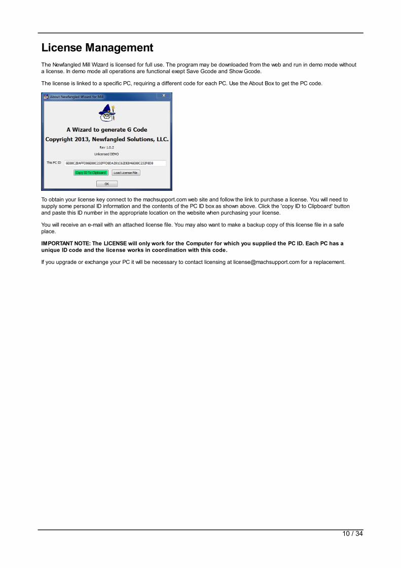
License ManagementThe Newfangled Mill Wizard is licensed for full use. The program may be downloaded from the web and run in demo mode withouta license. In demo mode all operations are functional exept Save Gcode and Show Gcode.
The license is linked to a specific PC, requiring a different code for each PC. Use the About Box to get the PC code.
To obtain your license key connect to the machsupport.com web site and follow the link to purchase a license. You will need tosupply some personal ID information and the contents of the PC ID box as shown above. Click the 'copy ID to Clipboard' buttonand paste this ID number in the appropriate location on the website when purchasing your license.
You will receive an e-mail with an attached license file. You may also want to make a backup copy of this license file in a safeplace.
IMPORTANT NOTE: The LICENSE will only work for the Computer for which you supplied the PC ID. Each PC has aunique ID code and the license works in coordination with this code.
If you upgrade or exchange your PC it will be necessary to contact licensing at [email protected] for a replacement.
10 / 34

Job ControlNewfangled solutions Mill wizard is oriented around a Job concept. A Job will always start with a New Job operation, where the jobmaterial, unit of measure, cutting strategy, and code comment selection will be made. This will be followed by a Tool Selection.Once these operations have been selected one or more operations may be added to the job.
A job may be saved to a file. A saved job may be re-opened and one or more of its operations may be edited. A new G code filecan be created for this session. The job file may be viewed as a template to a job. For example, a job file could be created to makea pipe flange. It would consist of a center circle cutout, a bolt circle, possibly repeated for a center drill, deep drill and counterbore,followed by an outside circle cut.
The template job file could be opened and just the diameter of the cuts edited and a new g code generated.
The current list of operations will be displayed in the list box on the left side of the main screen. By selecting an item on the list itmay be moved up or down in the list by clicking the arrows to the right of the list. The right click also allows Edit, delete or copy.
Copy will make a copy of the selected operation and add it to the list directly below the selected item. This is useful in severalways.
Consider a bolt circle. This requires 2 or more drill operations, first with a center drill to a shallow depth followed by a larger drill tofull depth. Possibly 2 or 3 drills may be needed to get to full diameter. Finally, a mill operation may be needed to make acounterbore over the hole. Each of these operations is the same, except for the depth of drill.
A bolt circle operation may be created, and values for diameter, number of holes, start angle, etc set. Once added to the job it canbe copied to add a duplicate operation. That operation may be edited to change the depth of drill. This can be repeated asneeded to get the full operation.
When a job is complete its Gcode must be Saved by clicking the save button. The Job file may also be saved by selecting save jobin the main menu bar.
11 / 34

New JobThe first session of the Mill Wizard must begin with a new job setup, entered by the NewJob menu slection. This opens a dialogwhere the job properties are set.
IMPORTANT NOTE: Hitting 'New Job' or 'open job' after working in a job file will close the current job file. Make sureall work is saved before selecting 'new job' or 'open job' on the menu bar to prevent losing your current work.
1. A material must be selected from the list of materials displayed. This allows the tool select screen to calculate theappropriate spindle RPM and feed rate.
You may edit the material list with the Material choice under the Config menu. You should edit this list to include thematerials and associated speed and feed data you will use.
2. If you require some special G code setup for your machine, for example, initalizing a tool changer, you may enter one ormore lines of Gcode in the box. Be aware, the wizards will not make any check for the validity of this code.
3. The Mill Wizards will operate in either Metric or Inch units. This selection is made in the new job dialog and carries to alloperations in the job.
4. A Z cut strategy box allows the selection of either making Z steps to be equal or to follow the entered valuess. See CuttingStrategies for a complete explanation.
5. The Mill Wizard can add many useful comments into the gcode to identify sections of code and the settings selected foreach selection. These comments appear in the code but have no effect on its running. However, some machines have veylimited program memory and the comments will take up space. If it is desired to eliminate comments the Use Commentscheck mark may be un-checked.
6. The rapid height and clearance settings will apply to each operation in the job. Rapid is the height above the work at whichthe machine may make any X,Y move safely from hitting any clamps or hold down devices. Each operation will make a moveto the Rapid height at the start and then make an X,Y move to the starting point.
7. The Clearance is the height above the work at which Z down moves change from a rapid (G0) move to a feed rate (G1)move. See Cutting Strategies for a complete explanation.
12 / 34

Tool SelectAll jobs will begin with a tool selection. If the same tool will be used for several operations only one tool select is needed. A new toolcan be selected in a job whenever needed between operations. All Manual overrides (info typed into the second dialog box) will notchange the original information in the Tool Table. Re-selecting the identical tool in the top dialog will reset the fields to the originalvalues.
A ToolTable is provided and shown in the top drop down box. If a tool is selected from the table it will automaticaly fill the tooldiameter, units, flutes, tool type and ramp angle fields. You may change the fields as you need. The tool table is a startingpoint for quickly filling the required fields.
Overriding the Selected Tool Fields
A tool number can be entered. The number will be used in T commands.Enter the cutting diameter of the tool.Select the units for the tool. This allows mixing of units within a job- you may use MM tools on an INCH job, or INCH tools ona MM job. The wizard will automaticaly make the correct unit conversions.The number of flutes or cutting tips on the tool.When the tool is making a Z down move into new material it will follow the ramp angle specified. Typical angles will be 3 to 10degrees. An entry here of 90 degrees will cause the tool to plunge straight down into the work.
Note: The tool diameter and tool type are used to determine a Surface Speed and chip load based on the material chosenin the New Job screen and the material table. See material for an explanation of the feed rate calculation. You may changethe speed and chip load if you wish.
Calc Buttons - Recalculate with entered values
Selecting the 'Calc Tool Properties' button will calculate the Tool properties from the data entered into the above dialog box.The result is a calculated surface feet per minute and chip load.The surface feet per minute and chip load fields can be changed from the calculated values simply by typing new values intothe boxes.Selecting the 'Calc Feed and Speed' button will populate the boxes in the Feed Speed section of the screen from thecurrent values in the Tool properties section of the screen.Any of the Feed Speed values can be changed by typing a value in the appropriate box.Red Values in the Feed Speed section indicate values that have been limited by the values entered into the Machine LimitsTable.
Note: When the tool diameter, number of flutes, or tool type are changed the program will automatically calculate the SFM,chip load, Speed (RPM) and feed rate.
If using coolant check the appropriate boxes.
13 / 34

GcodeThis buton will display a screen showing all the current gcode produced for this job. Note this button will be disabled when runningin demo mode. Please license your copy of the Newfangled Mill Wizard.
14 / 34

SaveThis button will verify if you want to save the file. When selecting 'yes' an M9 and M30 will be written at the end of the file and thefile saved to the selected location.
15 / 34

Milling OperationThe wizard supports several common milling operations
Surfacing stockCutting a rectangleCutting a circleKeyway SlotCut a slot on an Arcengraving TextThread Milling
16 / 34
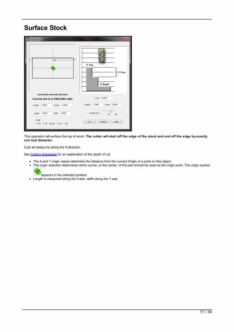
Surface Stock
This operation will surface the top of stock. The cutter will start off the edge of the stock and end off the edge by exactlyone tool diameter.
Cuts wil always be along the X direction.
See Cutting stragegies for an explanation of the depth of cut.
The X and Y origin values determine the distance from the current Origin of a point on this object.The origin selection determines which corner, or the center, of the part should be used as the origin point. The origin symbol
appears in the selected position.Length is measured along the X axis, width along the Y axis.
17 / 34

Cut a RectangleThis operation will cut a rectangle, either inside or outside of the specified measurements. Note this is just a cut around the edge,it is not a pocket operation.
A corner radius may be specified. If the radius is Zero an outside cut will have square corners. An inside cut will always have atleast a tool radius in the corners.
The rectangle is defined by an X and Y pair and an origin setting that determines a starting corner, or the center, of the rectangle.The Length is measured in the X direction, the width is measured in the Y direction.
The tool will cut inside or outside of the specified rectangle. It will go down at a ramp angle as set for the tool.
See Cutting strategies for an explanation of the depth of cut.
18 / 34
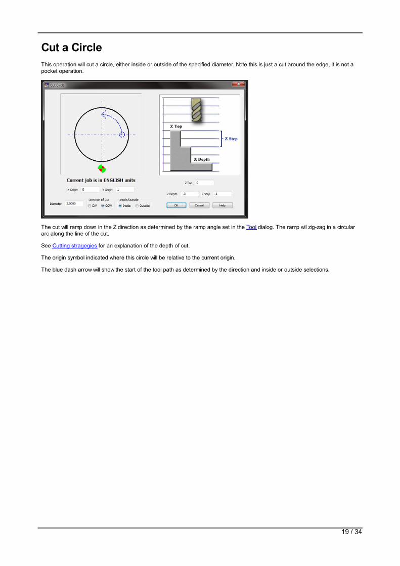
Cut a CircleThis operation will cut a circle, either inside or outside of the specified diameter. Note this is just a cut around the edge, it is not apocket operation.
The cut will ramp down in the Z direction as determined by the ramp angle set in the Tool dialog. The ramp wll zig-zag in a circulararc along the line of the cut.
See Cutting stragegies for an explanation of the depth of cut.
The origin symbol indicated where this circle will be relative to the current origin.
The blue dash arrow will show the start of the tool path as determined by the direction and inside or outside selections.
19 / 34

Keyway SlotWith this operation you can cut a slot from any point at a specified angle.
See Cutting strategies for an explanation of the depth of cut.
The X and Y origin entries determine the start point of the slot.
Length and angle determine the end of the slot.
The slot width determines the width. If a finish amount is specified, the first passes will cut to a width less than specified by thefinish amount. A final pass will be made around the slot to obtain the finished size.
20 / 34
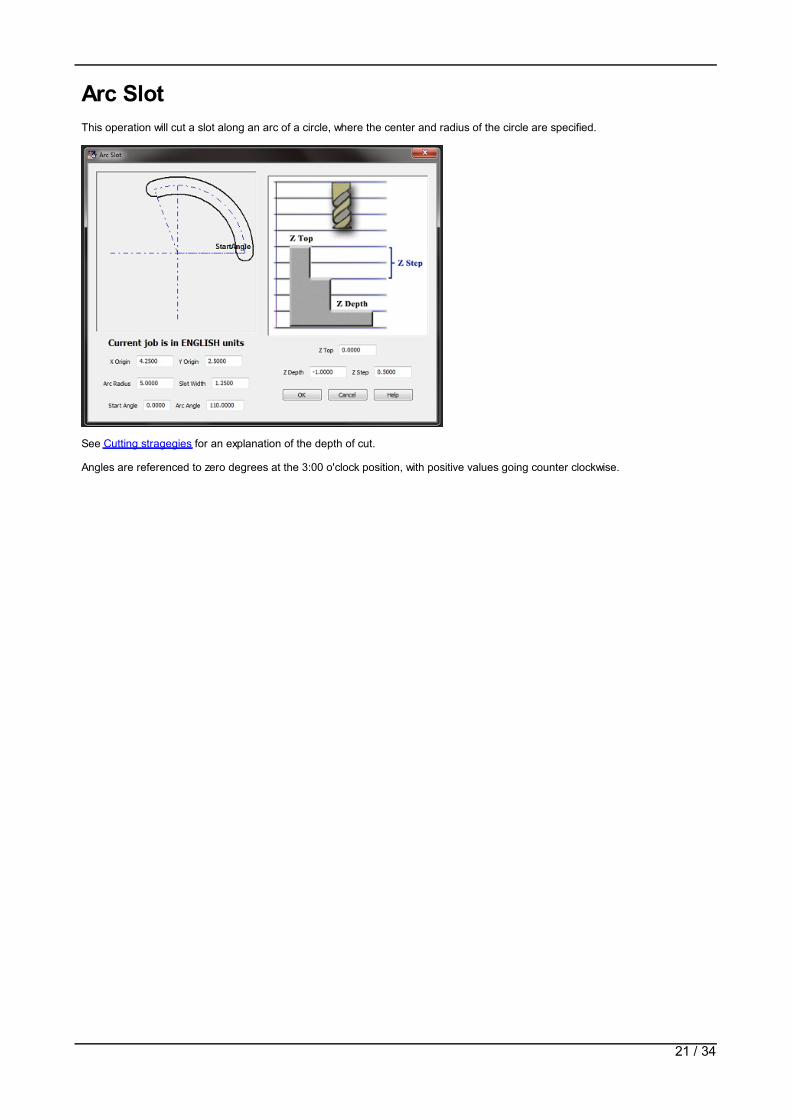
Arc SlotThis operation will cut a slot along an arc of a circle, where the center and radius of the circle are specified.
See Cutting stragegies for an explanation of the depth of cut.
Angles are referenced to zero degrees at the 3:00 o'clock position, with positive values going counter clockwise.
21 / 34

EngraveThis operation will engrave single stroke text in a straight line. It is only intended for simple labeling or numbering of parts.
The text start point refers to the lower left hand corner of a box surrounding the first character of the text. Character widths vary asappropriate for each character - an "I" will be in a box less wide than a "W". All letters are the same height. The text size iscontrolled by entering the text height. The text length box is displayed to indicate the approximate length required for the enteredtext at the current height setting.
The font is a Borland graphic format. A default block letter font is included with the wizards. Additional fonts can be found on theweb. One site is http://ncplot.com/stickfont/stickfont.htm where a more elaborate font to gcode program is available, as well as aselection of fonts. There is also a font editor avilable.
22 / 34

Thread MillThe wizard can generate code for thread milling operations.
This operation wil generate a single pass cut for the specified thread configuration.
If using metric units enter the thread pitch in mm. If English units enter the number of threads per inch.
23 / 34

Pocket OperationsNewfangled Solutions Mill Wizard provides two pocket opertions.
Rectangular pocketCircular pocket
24 / 34
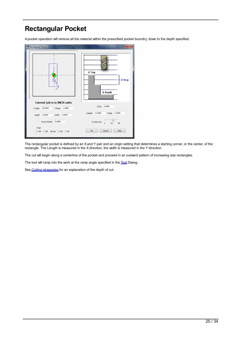
Rectangular PocketA pocket operation will remove all the material within the prescribed pocket boundry, down to the depth specified.
The rectangular pocket is defined by an X and Y pair and an origin setting that determines a starting corner, or the center, of therectangle. The Length is measured in the X direction, the width is measured in the Y direction.
The cut will begin along a centerline of the pocket and proceed in an outward pattern of increasing size rectangles.
The tool will ramp into the work at the ramp angle specified in the Tool Dialog.
See Cutting stragegies for an explanation of the depth of cut.
25 / 34

Circular PocketA pocket operation will remove all the material within the prescribed pocket boundry, down to the depth specified.
The circular pocket will begin in the center of the circle and make a helical ramp down with the ramp angle specified in the ToolDialog.
Effective tool diameter is the actual diameter multipled by the % step over value. Step over values greater than 50% may leaveuncut sections.
The circle will make increasing radius arcs until the pocket reaches the specified diameter.
See Cutting stragegies for an explanation of the depth of cut.
26 / 34

Drill OperationsNewfangled Solutions Mill Wizard supports 4 drill operations, Line, rectangle,circle, and list.
All four operations support 6 drill cycles.
G81 DrillG83 deep drillG73 Peck drillHand drillMill a circleMill a circular pocket
The first three are the common Gcode cycles. Hand Drill will be useful on a mill that has a hand operated quill. Often it is desired tohand feed a drill, particularly on very small drills, or with taps in a tap head. In this cycle, each XY move is made and then an M01stop is executed. Mach will wait for the operator to drill the hole, and then press the Cycle Start key to continue.
The mill circle or circle pocket are useful for operations like spot facing a bolt pattern, or for hole patterns when larger holes arerequired than are practical to drill. Note that the circle option assumes you first make a drilled hole then enlarge a circle around it.If you require a full pocket cut choose Pocket instead of Circle.
The drill cycles are:
drill a circle- Bolt circle- of holesDrill a series of holes along a lineDrill in a rectangular patternDrill a series of holes imported from a spreadsheet
27 / 34

Drill a Circle of Holes - Bolt Circle
This operation will drill as many holes as needed along a circle. The circle is specified by an XY value for the center and thediameter of the circle.
The first hole of the circle will be at the 0 degree, or max positive X value, unless a starting angle is specified.
The holes may be of any of the six type as explained inDrilling operations
28 / 34

Drill Line of Holes
This operation will drill a series of evenly spaced holes along a straight line. The line is specified by an XY value for the start of theline and an angle.
The number of holes is specified and the increment between the holes.
The holes may be of any of the six type as explained in Drilling operations
29 / 34
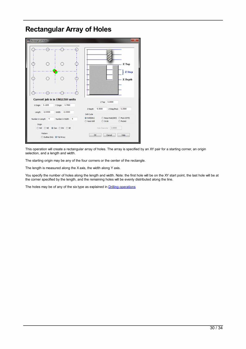
Rectangular Array of Holes
This operation will create a rectangular array of holes. The array is specified by an XY pair for a starting corner, an originselection, and a length and width.
The starting origin may be any of the four corners or the center of the rectangle.
The length is measured along the X axis, the width along Y axis.
You specify the number of holes along the length and width. Note: the first hole will be on the XY start point, the last hole will be atthe corner specified by the length, and the remaining holes will be evenly distributed along the line.
The holes may be of any of the six type as explained in Drilling operations
30 / 34

List of Holes
This operation will drill holes at a list of XY pairs. The list may be entered into the table manually or specified in a file of commaseparated values (commonly called a CSV file). This file may be generated by using many different software programs.
You can also enter values directly into the grid control. If more than 20 holes are needed, another list of holes operation can berun with the remaining coordinates.
The holes may be of any of the six type as explained in Drilling operations
31 / 34

4th Axis OperationsThe Newfangled Solutions Mill Wizard offer two operations that use a 4th axis.
Gear cuttingCutting a Spline on a shaft
32 / 34

SplineSpline cutting requires a 4th axis that can be arranged to support a shaft that is to be splined. The spline is cut by a flat bottomend mill.
The Y zero must be set so the tool is exactly centered over the center of the shaft.
Z zero is set with the tool exactly at the top surface of the shaft. The diameter of the shaft is not needed.
Note: the X cut direction may be in either direction by setting Xstart and Xend appropriately.
The first cut will ramp from the surface to full depth, then reverse over the same path to clear the ramp.
The Gcode will be generated as one file without using a subroutine. This makes it easier to handle the code, but makes the codelonger than using subroutines.
33 / 34

Gear CuttingGear cutting requires a 4th axis arranged to hold the blank from which the gear will be cut.
There are 4 possible setups for gear cutting. The blank may be in front or in back of the tool, and it may cut from left to right, orreverse. The Setup box is used to select the desired setting.
The cutter will be retracted from the work by the amount of the Clearance value, and set on the New Job Dialog.
The code will be generated as a series of X and Y moves followed by an A move to rotate the blank. Subroutines are not used,which makes the code simpler to save, but longer.
34 / 34