New structural engineering approach to enhance resilience ... · Local failure *ASME Section...
21
New structural engineering approach to enhance resilience against BDBE Naoto KASAHARA and Takuya SATO The University of Tokyo 4th IAEA Power Plant Life Management (PLiM) conference – 23-27 Oct. 2017 1
Transcript of New structural engineering approach to enhance resilience ... · Local failure *ASME Section...

New structural engineering approach
to enhance resilience against BDBE
Naoto KASAHARA and Takuya SATO
The University of Tokyo
4th IAEA Power Plant Life Management (PLiM) conference – 23-27 Oct. 2017
1

Contents
�Introduction
�Structural engineering approach to BDBE
�Fracture control and base technologies
�Failure modes under BDBE
�Development of failure mode maps
�Conclusions and future plan
2
Introduction
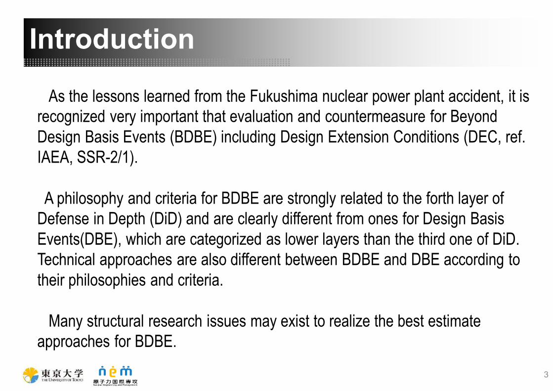
As the lessons learned from the Fukushima nuclear power plant accident, it is
recognized very important that evaluation and countermeasure for Beyond
Design Basis Events (BDBE) including Design Extension Conditions (DEC, ref.
IAEA, SSR-2/1).
A philosophy and criteria for BDBE are strongly related to the forth layer of
Defense in Depth (DiD) and are clearly different from ones for Design Basis
Events(DBE), which are categorized as lower layers than the third one of DiD.
Technical approaches are also different between BDBE and DBE according to
their philosophies and criteria.
Many structural research issues may exist to realize the best estimate
approaches for BDBE.
3

4
Large accident
Rare
(Meteorite collision, etc.)
Medium accident
Infrequent
(Excessive
earthquake, etc.)
Small accident
Frequent
(Components
malfunction, etc.)
Efforts to
prevent
Ignore
(Safety myth)
Evacuate
Actual accident frequency Binary approach Continuous approach
Different approach between small accident and Large accident
DB
EB
DB
E
Efforts to
prevent
Efforts to
mitigate
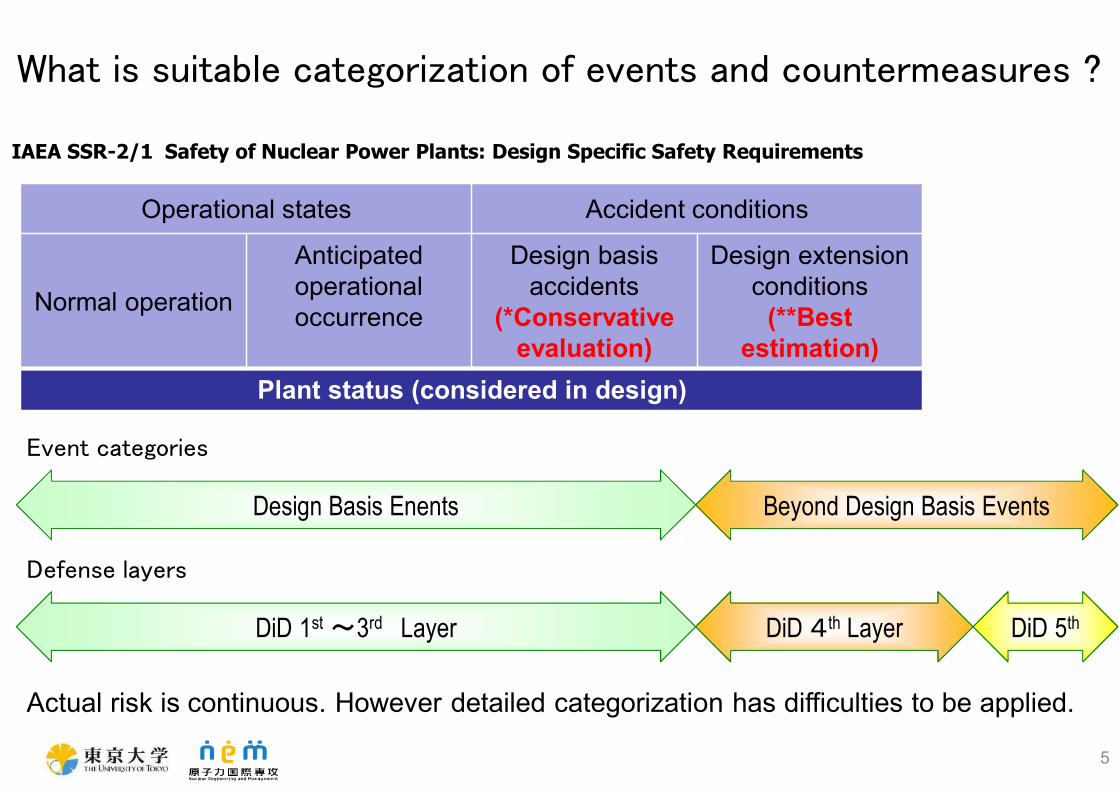
Operational states Accident conditions
Normal operation
Anticipated
operational
occurrence
Design basis
accidents
(*Conservative
evaluation)
Design extension
conditions
(**Best
estimation)
Plant status (considered in design)
IAEA SSR-2/1 Safety of Nuclear Power Plants: Design Specific Safety Requirements
DiD 1st〜3rd Layer DiD 4th Layer
Design Basis Enents Beyond Design Basis Events
DiD 5th
What is suitable categorization of events and countermeasures ?
Actual risk is continuous. However detailed categorization has difficulties to be applied.
Event categories
Defense layers
5
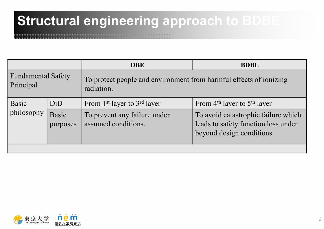
DBE BDBE
Fundamental Safety
PrincipalTo protect people and environment from harmful effects of ionizing
radiation.
Basic
philosophy
DiD From 1st layer to 3rd layer From 4th layer to 5th layer
Basic
purposes
To prevent any failure under
assumed conditions.
To avoid catastrophic failure which
leads to safety function loss under
beyond design conditions.
6
Structural engineering approach to BDBE

Various failure modes
Large
deformation
Collapse/
Break
Example: Design and countermeasure of piping
Prevention of all
failure modes
Cracks
Prevention of
catastrophic failure
DBE BDBE
7
き裂の貫通によるリーク
(先に生じる)
破断(ブレイク)
き裂の貫通によるリーク
(先に生じる)
延性破壊(ブレイク)
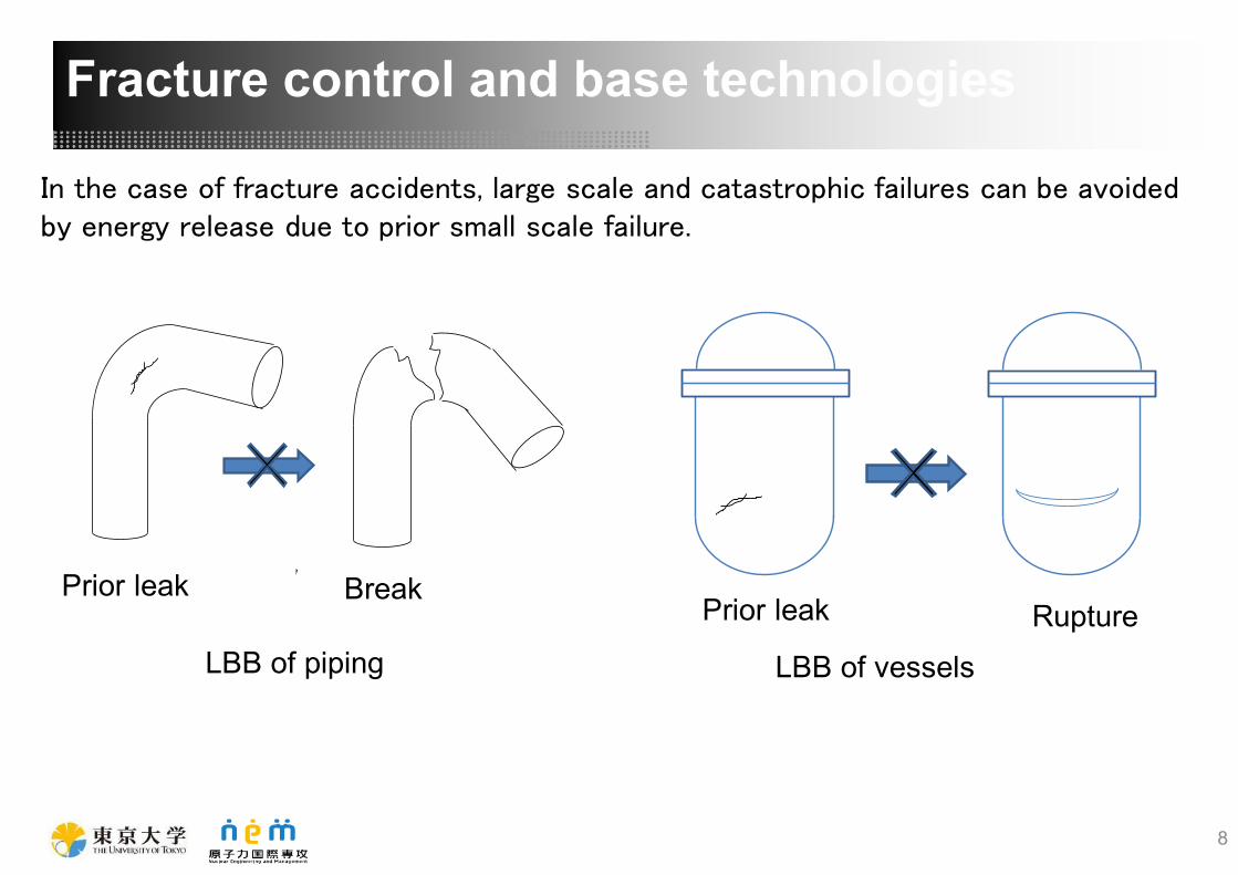
LBB of piping
In the case of fracture accidents, large scale and catastrophic failures can be avoided
by energy release due to prior small scale failure.
Prior leak BreakPrior leak Rupture
LBB of vessels
8
Fracture control and base technologies
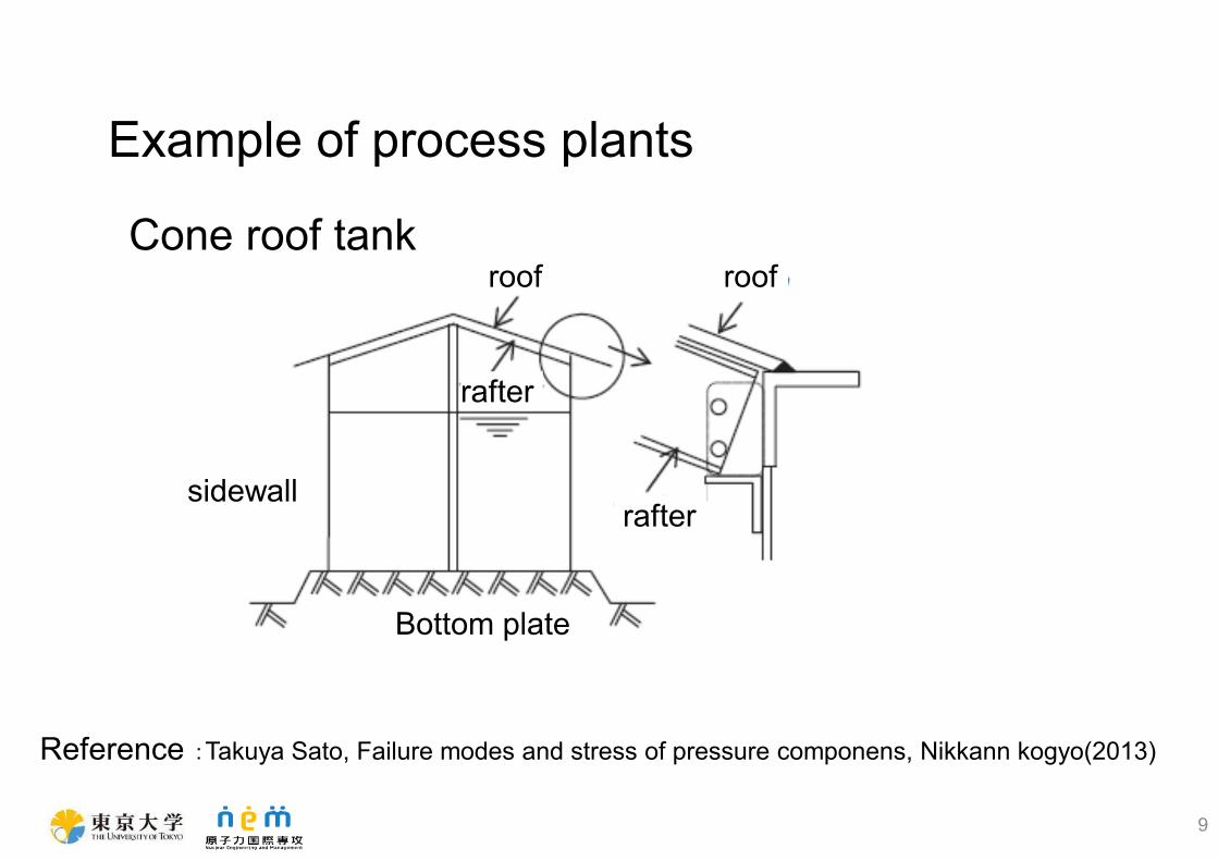
Example of process plants
Cone roof tank
Reference :Takuya Sato, Failure modes and stress of pressure componens, Nikkann kogyo(2013)
9
sidewall
Bottom plate
roof roof
rafter
rafter

Example of racing cars
Monococqe body to protect cockpit
10
(1) Clarification of failure modes
Failure modes of BDBE, which are different from DBE
(2) Identification of dominant parameters of failure for best estimation
Design criteria sometimes adopt conservative parameters
(Ex. Peak Ground Acceleration for seismic design)
(3) Relative strength evaluation among failure modes and locations
It can identify order of locations with failure modes . Absolute
strength is not necessary.
Base technologies of fracture control
11

[Experimental observation]
Fatigue failure by cyclic strain
[Conventional assumption]
Collapse and brake by the
maximum acceleration
[Conventional assumption]
Ductile fracture of PV and CV by high
temperature and pressure
Failure modes after core damage
[Experimental observation]
Local failure of CV by high
temperature and pressure
[Fukushima accident analysis]
Buckling and Ductile failure by
excessive outer pressure
Failure modes at excessive earthquake
12
Failure modes under BDBE

D u c t i l e f r a c t u r e
E l a s t i c P l a s t i c
b u c k l i n g
C o l l a p s e
L a r g e p l a s t i c
d e f o r m a t i o n
F a t i g u e f a i l u r e
Postulated failure modes under DBE
Exc
essi
ve
def
orm
atio
n
Lo
cal b
ou
nd
ary
failu
re
B r i t t l e f r a c t u r e
C r e e p r u p t u r e
D u c t i l e f r a c t u r e
L o c a l f a i l u r e
E l a s t i c P l a s t i c
b u c k l i n g
C r e e p b u c k l i n g
C o l l a p s e
L o c a l d u c t i l e
f r a c t u r e
Very low cycle fatigue
Possible failure modes under BDBE
DBE:
Conservative evaluation against all failure modes
BDBE:
Best estimation for each failure mode
Tran
siti
on
fro
m d
efo
rmat
ion
to
bo
un
dar
y fa
ilure
Tran
siti
on
acco
rdin
g t
o lo
ad
con
dit
ion
s
Gro
ss b
ou
nd
ary
failu
re
13

Temperature and internal
pressure are controlled
Reactor vessel model with the
simulation material(Pb)
Failure at 50℃ 0.57MPa 4.2h Failure at 50℃ 0.57MPa 3.8h
Ductile fracture at the plane
portion
Failure modes are different between two vessels under same loadings.
Failure of vessels under high pressure
Local failure at the structural
discontinuity
14
Development of failure mode maps

Strain limit equation(ASME*)
αsl : Material constant m2 : Material constant εLm : Strain limit under multiaxial state
εLu : Strain limit under uniaxial state Tr : Triaxial factor(Hydro static stress/Mises stress)
1/3 >1/3
Uniaxial state Multiaxial state
εLuεLm
StrainεLuεLm
σuσ1 for Tr1
Stress-strain curve
σy
A
B
σ1
Tr1
Hydrostatic stressσH1
Uniaxial state
Tr = 1/3
Fracture surface
Hydro static
stress limit
B
Ductile fracture
Local failure
*ASME Section VIII-Division2 Criteria and Commentary
A
15
Proposal of failure mode map for high pressure vesselRelative strength evaluation between ductile fracture and local failure
with dominant parameters

AccelerationAcceleration
Ratchet Deformation Collapse
Failure modes under excessive seismic load
8
Nakamura, Izumi, and Naoto Kasahara. 2016. “Trial Model Tests With Simulation Material to Obtain Failure Modes of Pipes Under
Excessive Seismic Loads.” In Volume 8: Seismic Engineering, V008T08A019. ASME.
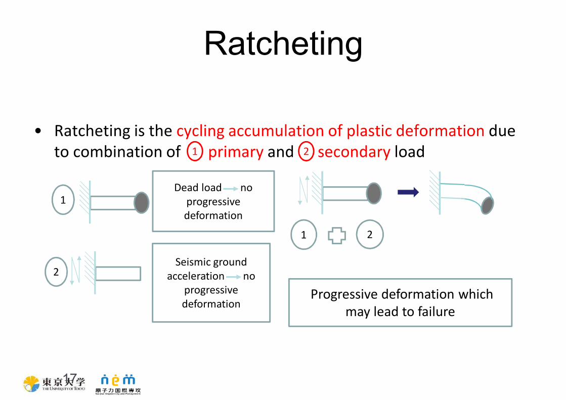
Ratcheting
17
• Ratcheting is the cycling accumulation of plastic deformation due
to combination of primary and secondary load
2
1
Progressive deformation which
may lead to failure
Dead load no
progressive
deformation
Seismic ground
acceleration no
progressive
deformation
1 2
1 2

18
The dynamic responses of amplification factor have some relation with the
frequency effect on ratchet diagram
Proposed ratchet diagram
0
4
8
12
0 0.5 1 1.5 2 2.5 3
20gal
200gal
400gal
600gal
800gal
1000gal
1500gal
Dyn
am
ic d
isp
./st
ati
c d
isp
.
Amplification factor
graph
Identification of dominant parameters of failure for best
estimation
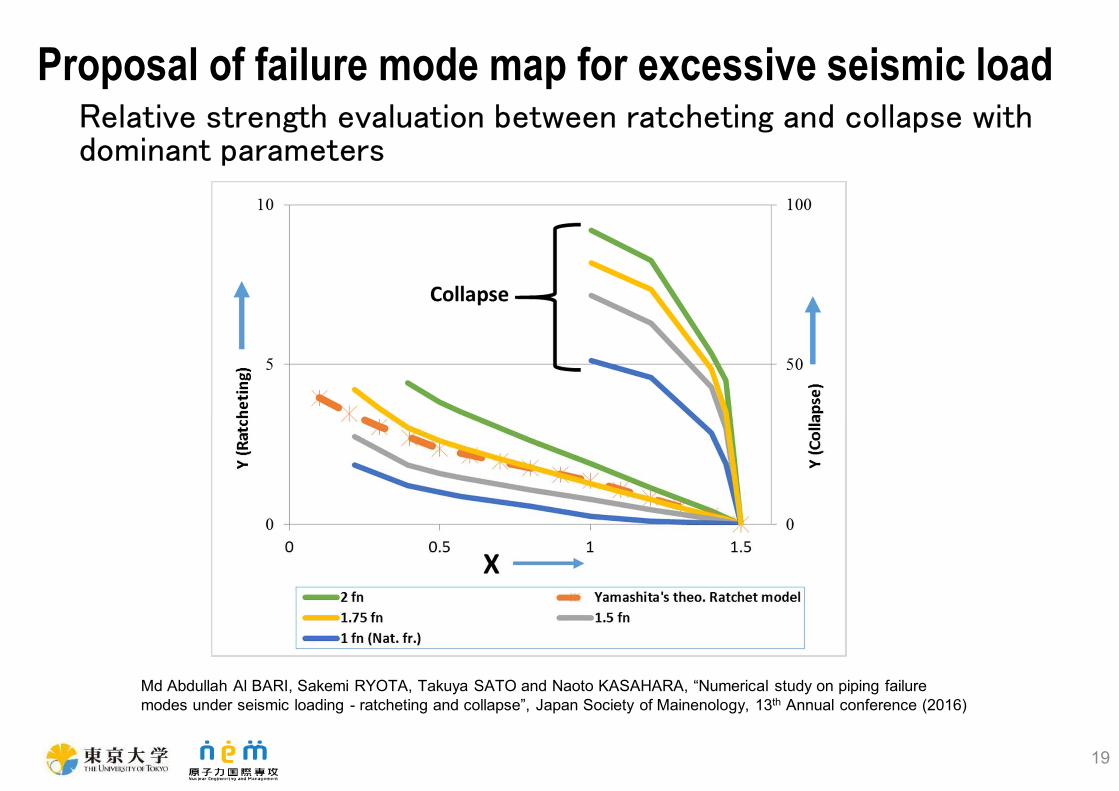
Proposal of failure mode map for excessive seismic load
Md Abdullah Al BARI, Sakemi RYOTA, Takuya SATO and Naoto KASAHARA, “Numerical study on piping failure
modes under seismic loading - ratcheting and collapse”, Japan Society of Mainenology, 13th Annual conference (2016)
19
Relative strength evaluation between ratcheting and collapse with
dominant parameters

[Controlled failure mode]
Ratcheting and Fatigue damage
with plastic cycles
20
[The worst failure mode]
Ductile fracture of large parts
of vessels
Countermeasure against high
temperature and pressure
[Controlled failure mode]
Local failure at limited area of
structural discontinuity portions
[Resilient counter measure]
Limitation of a location and a leak
rate by identification of failure
portion and mode
Proposals of fracture control system for nuclear plants
Countermeasure against
excessive seismic loads
[The worst failure mode]
Collapse or break of hole section
of pipe
[Resilient counter measure]
Maintain cooling function
Early recovery by replacing deformed pipes
Conclusions
� As structural engineering approach to BDBE, application of
fracture control concept was proposed.
� To realize fracture control, next base technologies were
studied. � Failure modes under BDBE were clarified
� Dominant parameters for best estimation were identified
� Failure mode maps were proposed to evaluate relative strength
among different failure modes.
21