New results of large-scale testing of high-tensile steel … · components of the TECCO ... G65/2 2...
12
APSSIM 2016 – PM Dight (ed.) © 2016 Australian Centre for Geomechanics, Perth, ISBN 978-0-9924810-5-6 APSSIM 2016, Brisbane, Australia 709 New results of large-scale testing of high-tensile steel meshes and soil nails for slope stabilisation and validation of modelling software R Bucher Geobrugg Australia Pty Ltd, Australia C Wendeler Geobrugg AG, Switzerland P Baraniak Bern University of Applied Sciences, Switzerland Abstract The stability of newly cut or natural slopes is an important issue of geotechnical engineering. Regardless of the scale of the project, the design and the execution have to assure maintenance-free and, more importantly, safe utilisation of the slope. Nowadays, a geotechnical engineer can choose from a number of different, available slope stabilisation methods. Nevertheless, one of the most frequently chosen methods is soil nailing in combination with flexible facing. In this configuration, the soil nailing is designed to stabilise deep-seated instabilities, while localised instabilities have to be stabilised by the flexible facing, typically represented by high-tensile steel wire mesh. In order to assure proper slope stabilisation, the soil nails and the flexible facing have to act as one integrated system. Such a system has been tested lately in large scale within this R&D project supported by the Swiss Commission for Technology and Innovation (CTI). The large-scale setup, widely described in Cała et al. (2013), consisted of an inclinable large box (12 × 10 × 1.2 m), soil material, soil nails, high-tensile steel wire mesh, steel plates (linking nail heads and mesh), connection clips (linking two sheets of mesh), and boundary ropes. The entire setup was lifted up on one side to imitate the inclination of the slope. While lifting the box up, several measurements were taken, e.g. tension forces and bending moments in the nails or deformation of the mesh. In total, 31 large-scale tests were conducted, at first to check the testing setup and later to test the interactions of the nails and high-tensile steel mesh, which were put together in different arrangement and configurations. The most important testing variables were soil material, nail pattern, type of steel wire mesh and connection plate. The main aim of this paper is to present the analysis of the performance of three meshes composed of 2, 3 and 4 mm diameter wire, tested in comparable conditions (the same soil conditions, nail pattern and connection plate). The purpose of this analysis was to show the distinction in bearing capacity and range of deformation of meshes produced from the same steel but of different wire diameter. This analysis was also used for the purpose of validation of already existing dimensioning concept based on small scaled laboratory tests. 1 Introduction Surficial slope stabilisation using flexible facings has been in use for more than 30 years. Firstly, the slope surface was stabilised using wire rope nets, gabion meshes or erosion control mats. Rather than using global safety calculations, problems with local, surficial instabilities were usually solved based on the rule of thumb. In such cases, the choice of facing, nail type and nail pattern was dictated by the intuition of an engineer and was not supported by any kind of geotechnical design. That situation changed about two decades ago when the dimensioning concept for shallow slope instabilities was developed. One can now easily model the surficial slope stabilisation system and adapt the nail pattern to local slope conditions. Nowadays, the dimensioning concept is available as an online tool that makes the calculations easier and faster. Lately, the dimensioning concept was verified in series of large-scale tests in the frame of research and development project founded by the CTI. The large-scale tests allowed also the development of new flexible facing systems. https://papers.acg.uwa.edu.au/p/1604_49_Bucher/
Transcript of New results of large-scale testing of high-tensile steel … · components of the TECCO ... G65/2 2...

APSSIM 2016 – PM Dight (ed.) © 2016 Australian Centre for Geomechanics, Perth, ISBN 978-0-9924810-5-6
APSSIM 2016, Brisbane, Australia 709
New results of large-scale testing of high-tensile steel meshes and soil nails for slope stabilisation and validation of modelling software
R Bucher Geobrugg Australia Pty Ltd, Australia
C Wendeler Geobrugg AG, Switzerland
P Baraniak Bern University of Applied Sciences, Switzerland
Abstract The stability of newly cut or natural slopes is an important issue of geotechnical engineering. Regardless of the scale of the project, the design and the execution have to assure maintenance-free and, more importantly, safe utilisation of the slope. Nowadays, a geotechnical engineer can choose from a number of different, available slope stabilisation methods. Nevertheless, one of the most frequently chosen methods is soil nailing in combination with flexible facing. In this configuration, the soil nailing is designed to stabilise deep-seated instabilities, while localised instabilities have to be stabilised by the flexible facing, typically represented by high-tensile steel wire mesh. In order to assure proper slope stabilisation, the soil nails and the flexible facing have to act as one integrated system. Such a system has been tested lately in large scale within this R&D project supported by the Swiss Commission for Technology and Innovation (CTI). The large-scale setup, widely described in Cała et al. (2013), consisted of an inclinable large box (12 × 10 × 1.2 m), soil material, soil nails, high-tensile steel wire mesh, steel plates (linking nail heads and mesh), connection clips (linking two sheets of mesh), and boundary ropes. The entire setup was lifted up on one side to imitate the inclination of the slope. While lifting the box up, several measurements were taken, e.g. tension forces and bending moments in the nails or deformation of the mesh. In total, 31 large-scale tests were conducted, at first to check the testing setup and later to test the interactions of the nails and high-tensile steel mesh, which were put together in different arrangement and configurations. The most important testing variables were soil material, nail pattern, type of steel wire mesh and connection plate. The main aim of this paper is to present the analysis of the performance of three meshes composed of 2, 3 and 4 mm diameter wire, tested in comparable conditions (the same soil conditions, nail pattern and connection plate). The purpose of this analysis was to show the distinction in bearing capacity and range of deformation of meshes produced from the same steel but of different wire diameter. This analysis was also used for the purpose of validation of already existing dimensioning concept based on small scaled laboratory tests.
1 Introduction Surficial slope stabilisation using flexible facings has been in use for more than 30 years. Firstly, the slope surface was stabilised using wire rope nets, gabion meshes or erosion control mats. Rather than using global safety calculations, problems with local, surficial instabilities were usually solved based on the rule of thumb. In such cases, the choice of facing, nail type and nail pattern was dictated by the intuition of an engineer and was not supported by any kind of geotechnical design. That situation changed about two decades ago when the dimensioning concept for shallow slope instabilities was developed. One can now easily model the surficial slope stabilisation system and adapt the nail pattern to local slope conditions. Nowadays, the dimensioning concept is available as an online tool that makes the calculations easier and faster. Lately, the dimensioning concept was verified in series of large-scale tests in the frame of research and development project founded by the CTI. The large-scale tests allowed also the development of new flexible facing systems.
https://papers.acg.uwa.edu.au/p/1604_49_Bucher/

New results of large-scale testing of high-tensile steel meshes and soil nails for slope stabilisation R Bucher et al. and validation of modelling software
710 APSSIM 2016, Brisbane, Australia
2 Objectives The goal of this paper is to present the comparison and optimisation possibilities of newly developed flexible facing systems. These considerations are based on the results of dimensioning concept and large-scale tests. Therefore, the flexible facing systems are introduced, followed by short description of the dimensioning concept, the online tool and the 1:1 testing method.
3 Flexible facing systems The flexible facing systems are always combined with soil nailing. In general, the flexible facing system is a composite of three steel elements: wire mesh, back plates and connection clips. The role of connection clips is to sew one mesh panel to another in such way that this connection will be at least as strong as the mesh itself. On the other hand, the mesh and the plates always act together. The mesh tightly covers the slope surface and takes the entire load from sliding soil mass and transmits it through the steel plate to the anchorage system. Since the performance of the whole system depends directly on the connection between the mesh and the plate, there is a lot of attention given to make this connection as efficient as possible. The most important strength characteristics of flexible facing systems, utilised also in dimensioning concept, are puncturing resistance on the upper edge of the spike plate and shearing resistance on the contact between the mesh and the plate. These characteristics are usually specified in laboratory investigations. These critical bearing resistances characteristic were also checked within the large-scale tests.
The elements of flexible facing systems used within the frames of this research project are standard components of the TECCO® system: three different mesh types, two different plate types and one, unified type of connection clip. The used mesh is a diamond-shaped chain-link mesh with the dimensions of 83 × 143 mm of a single mesh and an aperture of 65 mm. The mesh is produced out of 2, 3 and 4 mm high-tensile steel wires (tensile strength of steel ≥ 1,770 MPa). The steel plates are produced in two types: P33 (330 × 205 × 7 mm) and P66 (667 × 300 × 7 mm) having two corners along the longer diagonal dimension folded towards the slope (for better interlocking with the mesh). Table 1 presents the combinations of the mesh and the plates used within the project, together with their characteristics of puncturing and shearing-off resistance.
Table 1 Puncturing and shearing-off resistance of meshes and plates combined in flexible facing systems investigated within research project
Mesh type Wire diameter (mm)
Plate type Puncturing resistance (kN)
Shearing-off resistance (kN)
G65/2 2 P33 40 10
G65/3 3 P33 90 30
G65/4 4 P33 140 50
G65/4 4 P66 185 75
4 Dimensioning of flexible facings
4.1 Dimensioning concept The dimensioning concept, widely described in Cała et al. (2012), is a simplified method for calculation of surficial slope stabilisation, based on limit equilibrium method. The first assumption is that all the soil nails are installed in regular rhomboidal pattern (Figure 1). The dimensions of the rhomb created by the nails are a × 2b, where a is the horizontal nail distance and 2b is the distance between next nails in the line of the slope. The dimensioning concept assumes two kinds of failure mechanism of surficial part of the slope.

New methods for analysis and control
APSSIM 2016, Brisbane, Australia 711
The first mechanism assumes that the whole surficial layer, parallel to the slope surface, slides down the slope. In this case, the calculated soil body has dimensions of nail pattern a × b and the thickness t of sliding soil layer (Figure 2(a)). The second mechanism assumes that there is single-body or two-body wedge-like failure mechanism. This time, the sliding body is located among four nails and has dimensions of a × 2b and t (Figure 2(b)).
Figure 1 Arrangement of soil nails on the slope in regular rhomboidal pattern
Figure 2 Two types of failure mechanism of surficial slope layer: (a) soil layer parallel to the slope
surface; (b) wedge-like single or two-body mechanism depending on the vertical distance between anchors. Source: Geobrugg TECCO® brochure 2015
The thickness of an unstable soil layer varies usually between 0.5 and 2.0 m, and it is either indicated by slope investigations or assumed based on engineer’s experience, described in ‘TECCO Slope Stabilization System’, Summary of Published Technical Papers 1998–2011.
The dimensioning concept investigates the equilibrium of the soil body and the limit states of flexible facing systems and the soil nails, based on 2D geometry taking into account the failure condition of Mohr–Coulomb. In such cases, five so-called proofs of bearing safety have to be checked. The proofs of bearing safety that have to be checked depend on the type of failure mechanism. In case of slope-parallel instabilities; (Figure 2(a)), the proofs of safety are: 1) proof of the nail, against sliding-off, a surficial layer parallel to the slope; 2) proof of the mesh against puncturing; 3) proof of the nail to resistance of the nail to combined stress. In case of localised instabilities between the nails (Figure 2(b)), the proofs that have to be checked are: 4) proof of the mesh against puncturing force P on the upper edge of the plate; 5) proof of the mesh to selective transmit of the force Z into the nail.
The last two proofs of safety are the most important ones from the perspective of flexible facing system. In such a situation, an unstable soil mass is sliding down the slope, creating deformations above the lower nail and pushing on the upper edge of the spike plate fastened on this nail. At the same time the mesh is being

New results of large-scale testing of high-tensile steel meshes and soil nails for slope stabilisation R Bucher et al. and validation of modelling software
712 APSSIM 2016, Brisbane, Australia
tensioned and pulled down on the upper nail in the same cross-section. Figure 3 presents schematic the two-body wedge-like failure mechanism with deformations, puncturing force P and shearing-off force Z shown in the Figure 3. This theoretical sliding mechanism was confirmed by numerous field observations and the large-scale tests (Figure 4).
Figure 3 The schematic two-body wedge-like failure mechanism with deformation of the mesh,
puncturing force P and shearing-off force Z
Figure 4 Test site observations of the deformation of flexible facing system: a) the bright dashed line
traces the line of deformation; B) laser scanner picture that shows the sliding mechanisms (puncturing force P and shearing-off force Z)
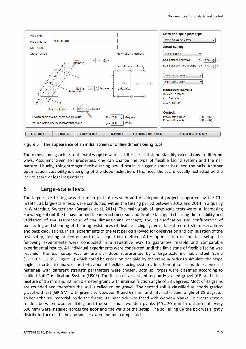
4.2 Design tool The online dimensioning tool is basically a digitalised version of previously described dimensioning concept. With use of a tool one can easily enter and change all the parameters needed to properly calculate the stability of surficial soil layer. These parameters are as follows: soil properties, slope angle, thickness of the surficial layer, type, inclination and pattern of the soil nail and of course type of the flexible facing system. Additionally, one can consider external loads of earthquake and streaming pressure. The calculations can be adapted to appropriate standards by changing the values of safety factors. Figure 5 presents the appearance of an initial screen of the online dimensioning tool.
New methods for analysis and control
APSSIM 2016, Brisbane, Australia 713
Figure 5 The appearance of an initial screen of online dimensioning tool
The dimensioning online tool enables optimisation of the surficial slope stability calculations in different ways. Assuming given soil properties, one can change the type of flexible facing system and the nail pattern. Usually, using stronger flexible facing would result in bigger distance between the nails. Another optimisation possibility is changing of the slope inclination. This, nevertheless, is usually restricted by the lack of space or legal regulations.
5 Large-scale tests The large-scale testing was the main part of research and development project supported by the CTI. In total, 31 large-scale tests were conducted within the testing period between 2012 and 2014 in a quarry in Winterthur, Switzerland (Baraniak et al. 2014). The main goals of large-scale tests were: a) increasing knowledge about the behaviour and the interaction of soil and flexible facing; b) checking the reliability and validation of the assumptions of the dimensioning concept; and, c) verification and confirmation of puncturing and shearing-off bearing resistances of flexible facing systems, based on test site observations and back calculations. Initial experiments of the test period allowed for observation and optimisation of the test setup, testing procedure and data acquisition method. After optimisation of the test setup the following experiments were conducted in a repetitive way to guarantee reliable and comparable experimental results. All individual experiments were conducted until the limit state of flexible facing was reached. The test setup was an artificial slope represented by a large-scale inclinable steel frame (12 × 10 × 1.2 m), (Figure 6) which could be raised on one side by the crane in order to simulate the slope angle. In order to analyse the behaviour of flexible facing systems in different soil conditions, two soil materials with different strength parameters were chosen. Both soil types were classified according to Unified Soil Classification System (USCS). The first soil is classified as poorly graded gravel (GP) and it is a mixture of 16 mm and 32 mm diameter grains with internal friction angle of 33 degrees. Most of its grains are rounded and therefore the soil is called round gravel. The second soil is classified as poorly graded gravel with silt (GP-GM) with grain size between 0 and 63 mm, and internal friction angle of 38 degrees. To keep the soil material inside the frame, its inner side was faced with wooden planks. To create certain friction between wooden lining and the soil, small wooden planks (60 × 30 mm in distance of every 500 mm) were installed across the floor and the walls of the setup. The soil filling up the box was slightly distributed across the box by small crawler and non-compacted.

New results of large-scale testing of high-tensile steel meshes and soil nails for slope stabilisation R Bucher et al. and validation of modelling software
714 APSSIM 2016, Brisbane, Australia
Figure 6 Test setup before the rupture of flexible facing, frame sizes and box frame empty
The nails used in tests were represented by threaded steel bars (ø 32 mm), encased by a corrugated PVC tube (ø 100 mm) and cemented to simulate the construction conditions. The nails were installed in the box in regular rhomboidal patterns of 2.5 × 2.5 m, 3.0 × 3.0 m and 3.5 × 3.5 m. Some of the nails were equipped with strain gauges in order to measure stresses occurring in the nails during testing procedure. All the nails were fixed to the steel frame with steel foot plates. Note that the measured stresses in the nails were quite similar, from place to place into the elements equipped with strain gauges.
The inclination of the test setup was measured constantly to have a reference scale for comparison of different flexible facing systems tested in varying conditions. The inclination was measured with an electrical inclinometer from company Tuck, with measuring resolution ≤0.14 degrees and possible measuring range 0–360 degrees. The inclination sensor had to be calibrated directly before each test. In order to double-check the inclination measurement, a simple free-weight goniometer was attached to frame and inclination scale was marked on the skid of the box.
The deformation of the flexible facing systems, were measured at every inclination step (0, 30 to 85 degrees in every 5 degrees) by pulse laser scanner. In general, the laser scanner measures distance by illuminating a target with a laser and analysing the reflected light. In our case, the values of deformations measured at certain inclination were later deducted from the values of the deformations at the initial state. The values of the maximum deformations were calculated from the whole area of the box. In order to avoid errors in the measurements the maximum deformation value was defined as the maximum deformation of an area of at least 0.25m². The horizontal and vertical angular resolution of the laser scanner was set to 0.02 degrees, resulting in a density of 2 × 10⁴ points / m² at 20 m distance and 1 × 10⁴ points / m² at 30 m distance and the accuracy of measurement of 7 and 10 mm, respectively.
6 Test results This section presents the comparison of results achieved from the calculations in dimensioning concept and the large-scale tests. The most quantitative and reliable unit for such comparison is the failure inclination of slope. In case of the dimensioning concept, the failure inclination of the surficial slope means that one or more of proofs of bearing safety of flexible facing are not fulfilled. On the other hand, in case of tests, the failure means that the flexible facing got ruptured around the anchor heads as expected and the test could not be continued. Ground failure (soil) without reinforcement occurs, when the value of angle of internal friction is overcome.
All calculations with the online tool were done using the same mesh types, soil strengths and nail patterns as used within the large-scale tests. Moreover, the calculations were done with all safety and partial factors (cohesion, friction angle, positive and negative loading etc.) set to 1.0 (means breaking level). Since the thickness of the test setup was 1.20 m, which is the same thickness of the soil layer was used in the calculations.

New methods for analysis and control
APSSIM 2016, Brisbane, Australia 715
The graphs in Figures 7 and 8 present the failure inclination depending on puncturing resistance of the flexible facing, tested and calculated with nail pattern 3.0 × 3.0 m and 3.5 × 3.5 m, respectively. The solid lines represent the inclination values calculated with online tool, while the dashed lines represent the inclination values measured during tests. Due to lack of information from the tests in round gravel with 3.5 × 3.5 m nail pattern, the failure inclination values were partly predicted.
Figure 7 The comparison of failure inclination depending on the puncturing resistance of flexible
facing system tested in large-scale tests and calculated with dimensioning concept. Tests and calculations with nail pattern 3.0 × 3.0 m
Figure 8 The comparison of failure inclination depending on the puncturing resistance of flexible
facing system tested in large-scale tests and calculated with dimensioning concept. Tests and calculations with nail pattern 3.5 × 3.5 m
The observations made on failure inclination show that for the same mesh, regardless of the soil conditions and nail pattern, the values of the inclination measured within the tests are always higher than the one calculated with the online tool. On the other hand, the difference in the failure inclination between measured and computed values increases always together with the strength of the flexible facing. Figure 7

New results of large-scale testing of high-tensile steel meshes and soil nails for slope stabilisation R Bucher et al. and validation of modelling software
716 APSSIM 2016, Brisbane, Australia
shows that the difference between calculated and measured values of failure inclination, with nail pattern 3.0 × 3.0 m, rises from 9 to 11% and 8 to 13% in the cases of testing of round gravel and sandy gravel, respectively. On the other hand, in the tests with 3.5 × 3.5 m nail pattern, the difference between calculated and measured values varies between 16 to 22% and 18 to 25% in case of round gravel and sandy gravel, respectively (Figure 8). These differences are mainly associated with some simplifications and model hypothesis, for example, the interaction between the mesh and nails is not considered. This allows to affirm that the model, although it describes the phenomenon adequately, is slightly conservative, compare to the reality.
Another interesting observation is that the difference in the failure inclination for calculated and measured values does not depend on the nail pattern. In case of the calculated values the difference was 10% and did not change with increasing puncturing resistance of the flexible facing system. In case of measured values (and partly predicted), the difference of the failure inclination increased together with the strength of the facing of about 10 to 16%.
In order to analyse the load bearing capacity and deformation behaviour of flexible slope stabilisation systems, laser scans at a steel frame inclination of 60° (average value of common road slopes) are compared with one another in the following. Figure 9 shows the measured deformation of a TECCO® G65/4 type high-tensile steel wire mesh with spike plate P66 (width of 66 cm) with round gravel and a nail grid of 3.5 × 3.5 m using threaded steel bars (ø 32 mm), the maximum value of the deformation observed is 0.5 m. Figure 10 shows the same situation with the same spike plate and nail arrangement as well as the same soil material. The only different is the mesh. Instead of a high-tensile steel wire mesh with a longitudinal tensile strength at least 250 kN/m and a wire diameter of 4 mm, a high-tensile steel wire mesh with the same mesh size but with a wire diameter of 3 mm and a tensile strength of at least 150 kN/m was used, in this case the maximum value of the deformation observed is 0.55 m. The stronger mesh is somewhat stiffer under the same conditions. It is subject to less deformation and the soil material slides downwards to a lesser degree.
Figure 9 Test No. 12, measured deformation (m) of the TECCO® mesh (m) G65/4 + P66, nail grid
3.5 × 3.5 m, round gravel 16–32 mm, α = 60°

New methods for analysis and control
APSSIM 2016, Brisbane, Australia 717
Figure 10 Test No. 14, measured deformation of the mesh (m) TECCO® G65/3 + P66, nail grid 3.5 × 3.5 m,
round gravel 16–32 mm, α = 60° dashed lines shows, that the horizontal offset nail, contribute to the rational transmission of force from nail to nail
If you compare Figure 10 with Figure 11, the following becomes clear: On the one hand, smaller spike plates are used (33 cm wide spike plate, type P33 instead of 66 cm wide spike plates, type P66). On the other, a high-tensile steel wire mesh is used with a wire diameter of 2 mm and a longitudinal tensile strength of at least 65 kN/m. The stabilising lateral influence of a smaller spike plate is weaker than with a larger one with sufficient bending stiffness. Furthermore, a somewhat weaker mesh under the same limiting conditions is somewhat more stressed, which becomes clear due to somewhat larger deformations with a wider bulge which slides downwards to a larger degree. In this last example, the maximum value of the deformation observed is 0.64 m.
Figure 11 Test No. 17, measured deformation (m) of the TECCO® mesh G65/2 + P33, nail grid
3.5 × 3.5 m, round gravel 16–32 mm, α = 60°
The differences between Figures 11 and 12 are the soil material used and the mesh. If a soil material with better interlocking properties and a much stronger steel wire mesh with identical mesh size and form are installed, much less deformation is to be expected.

New results of large-scale testing of high-tensile steel meshes and soil nails for slope stabilisation R Bucher et al. and validation of modelling software
718 APSSIM 2016, Brisbane, Australia
Figure 12 Test No. 13, measured deformation of the mesh TECCO® G65/4 + P33, nail grid 3.5 × 3.5 m,
sandy gravel 0–63 mm, α = 60°
The large-scale tests also show the positive influence of the installation of the spike plates in previously-created recesses. Creating troughs makes it possible to actively stretch the mesh during installation. This significantly reduces deformations when lifting the steel frame, which makes a significant effect on the load bearing capacity of the entire system. The mesh geometry in conjunction with the transmission of force from the mesh to the nail anchoring system also plays an important role. Since the introduction of high-tensile steel wire meshes with rhombus-shaped holes around the end of the 1990s, a nail grid was deliberately recommended whose nail rows are arranged laterally at an offset of half the horizontal distance between nails. Previously, square nail grids modelled after conventional rope nets were common. If horizontal nail distance ‘a’ is set to be identical to nail distance in fall line ‘b’, a field of ‘a × 2b’ is stretched between the nails. When observing the transmission of force from nail to nail (Figure 10), it becomes clear that it follows the mesh geometry. Supported by the most direct force distribution possible, this fact has a positive effect on the load bearing capacity and deformation behaviour of such flexible systems.
7 Verification of RUVOLUM® dimensioning concept The RUVOLUM® dimensioning concept (Rüegger et al. 2000) was developed on the basis of many years of experience in the area of flexible slope stabilisation systems and was verified based on model tests. The large-scale tests performed in the scope of the CTI research project makes it possible for the first time to examine the theoretical model approach and the underlying assumptions under quasi-realistic conditions and using repeatable tests. Figure 13 shows a two-body sliding mechanism which is trying to slide out between the nails and is prevented by the mesh cover and nails (Rüegger et al. 2000). Figure 14 illustrates the cross-section of the unstable block under the stabilising influence of the lateral spike plates. The fracture mechanism decisive for dimensioning has a width ‘ared’. The graphic analysis of the laser scan shows good agreement with the model approach in accordance with the RUVOLUM® concept. Comparative calculations are now to be performed. When doing so, a differentiation has to be made between the dimensioning situation while taking into account the corresponding partial safety factors according to EUROCODE 7 into account and the state of failure.

New methods for analysis and control
APSSIM 2016, Brisbane, Australia 719
Figure 13 Two-body sliding mechanism in the examination of instabilities near the surface in accordance
with the RUVOLUM® concept
Figure 14 Reduced cross-section as a result of the stabilising influence of the lateral spike plates or nails
in accordance with the RUVOLUM concept
For the back-calculation, the results of large-scale tests No. 11 using TECCO® G65/3 steel wire mesh, in combination with type P33 spike plates and threaded steel bars (ø 32 mm) as nails, with a sacrificial rusting away of 4 mm on the diameter, are to be used as an example. The nail grid was 3.5 × 3.5 m. The soil material was broken-up sandy gravel 0–63 mm, made of recycling material (previously described). The first superficial movements in all the area can be observed at an inclination of α = 53° (Figure 15(a)). The mesh was then punctured at α = 80° (Figure 15(b)). If the flexible slope stabilisation system used in test No. 11 is modelled using the RUVOLUM® software in accordance with EUROCODE 7 (recommends a partial safety factor: for the internal friction angle and the cohesion till 1.25, and for the model uncertainty till 1.10), a maximum slope incline of α = 50° results. For example, if the nail grid is reduced to 3.40 × 3.40 m, the permissible slope incline is increased to α = 53°.

New results of large-scale testing of high-tensile steel meshes and soil nails for slope stabilisation R Bucher et al. and validation of modelling software
720 APSSIM 2016, Brisbane, Australia
(a) (b)
Figure 15 Test No. 11 TECCO® G65/3 + P33, nail grid 3.5 × 3.5 m, sandy gravel 0–63 mm, α = 53°: (a) first superficial movements; and, (b) at failure at α = 80°
The results of the back-calculation with the software correlate quite well with the situation in which the first instabilities close to the surface were observed. If all partial safety factors are set to 1.00, the radius of the pressure cone increased to ζ = 0.30 m, the load bearing capacity of the mesh at point-by-point application of force at the upper nail with Z = 30 kN is fully utilised and if the nail inclination is assumed to be perpendicular to the slope surface as before, the break, calculated by the software, occur at a slope of α = 76°. This result also agrees very well with the test results.
8 Conclusion The large-scale tests performed create an ideal foundation for a better understanding of the load bearing capacity of flexible slope stabilisation systems, as well as for further development and adapting them to project-specific requirements. Considering the practical restrictions (crane 500 t), the size of the test frame seems to have been well-selected for simulating superficial instabilities. In supplementary tests, additional results on impacts to the nails and especially in the nail head area will be gathered. The results presented within the present paper show that the failure inclination of the surficial layer of the slope depends strongly on the type of flexible facing used for the surficial stabilisation. The differences of the results achieved from the large-scale tests and the dimensioning concept varies between 8 and 25%. This seems to confirm that the assumptions of the dimensioning model are right. The RUVOLUM® dimensioning concept based on laboratory tests seems to be on the safe side compared to the large-scale tests. Since the test setup presented in the paper, is the world’s first installation for artificially checking the surficial stability of slopes, the results achieved from the tests should be taken with certain reserve and should never be used as safety factors. The authors of this paper always recommend incorporation of safety factors for slope stability calculations.
References Baraniak, P & Schwarz-Platzer, K, Stolz, M, Shevlin, T & Roduner, A 2014, ‘Large scale field tests for slope stabilizations made with
flexible facings’, GEOHAZARDS 6, Kingston. Cała, M, Flum, D, Roduner, A, Rüegger, R & Wartmann, S 2012, TECCO Slope Stabilization System and RUVOLUM® Dimensioning
Method, Bad Langesalza, Beltz Bad Langesalza GmbH, http://www1.geobrugg.com/contento/Portals/35/ media/TECCO%20the%20book%20pre-announcement_en_screen.pdf
Cała, M, Stolz, M, Baraniak, P, Rist, A & Roduner, A 2013, ‘Large scale field tests for slope stabilizations made with flexible facings’, in Proceedings of EUROCK 2013, Rotterdam, Balkema.
Geobrugg, AG 2011, ‘TECCO Slope Stabilization System’, Summary of Published Technical Papers 1998–2011. Geobrugg, AG 2015, Geobrugg TECCO®, brochure. Rüegger, R, Flum, D & Haller, B 2000, Hochfeste Geflechte aus Stahldraht für die Oberflächensicherung in Kombination mit
Vernagelungen und Verankerungen, 2nd Building in Soil and Cliffs Colloquium at the Technical Academy of Esslingen, Germany.