New Real-time Capabilities in Modelica for Embedded …petfr27/MODPROD2010talks/... · New...
75
New Real-time Capabilities in Modelica for Embedded Systems Hilding Elmqvist Dassault Systèmes, Lund
Transcript of New Real-time Capabilities in Modelica for Embedded …petfr27/MODPROD2010talks/... · New...

New Real-time Capabilities in Modelica for Embedded Systems
Hilding ElmqvistDassault Systèmes, Lund
Content
Introduction to Modelica
Modelica for Embedded Systems
StateGraph - A New Formalism for Modeling of Reactive and Hybrid Systems
FMI - Functional Mockup Interface – Overview
Outlook

Introduction to Modelica
Content
Introduction
Need for Dynamic Behaviour Models
A language – Modelica
Organizing modeling knowhow – Modelica libraries
A solver – DymolaA solver – Dymola
Example
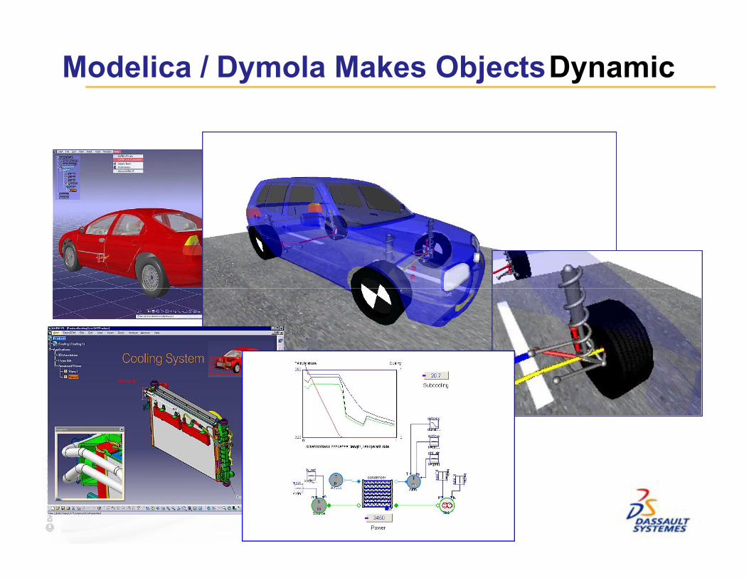
Modelica / Dymola Makes ObjectsDynamic

Model Knowledge
Dynamic system model knowledge• has been developed over many centuries• is stored in books, articles, reports and human minds • which computers can not access
A formal modeling
6
A formal modeling language is needed to capture and store models for reuse
Dynamic system model knowledge
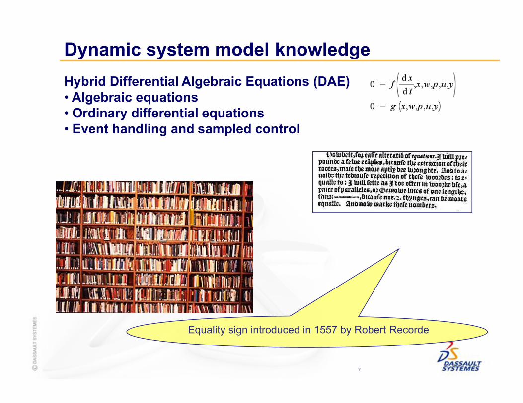
Hybrid Differential Algebraic Equations (DAE)• Algebraic equations• Ordinary differential equations• Event handling and sampled control
7
Equality sign introduced in 1557 by Robert Recorde
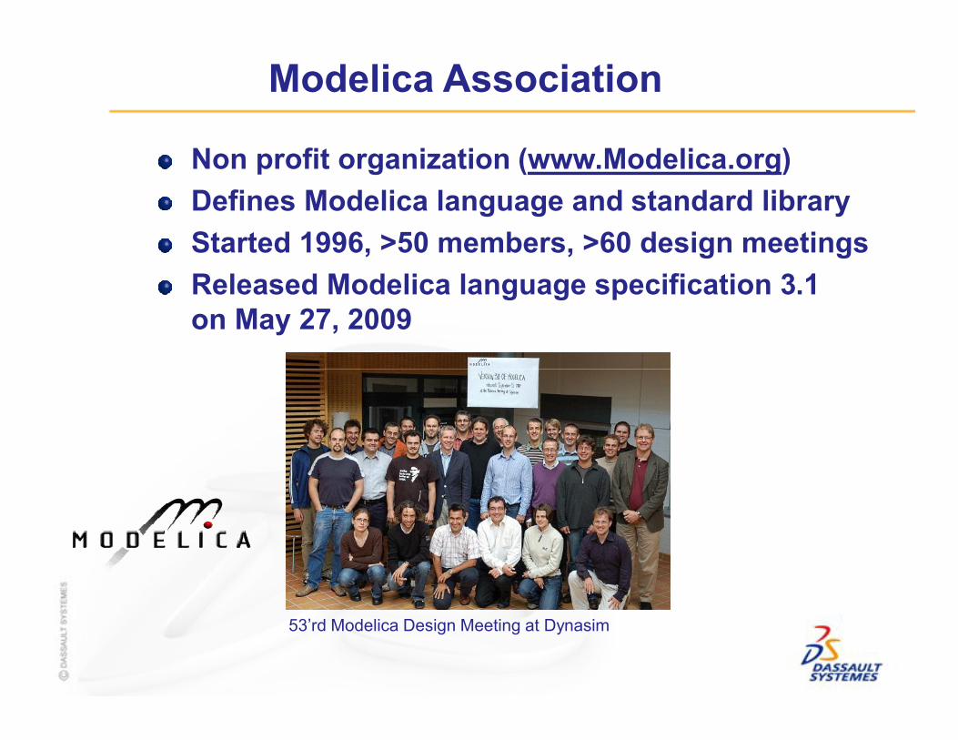
Modelica Association
Non profit organization (www.Modelica.org)
Defines Modelica language and standard library
Started 1996, >50 members, >60 design meetings
Released Modelica language specification 3.1 on May 27, 2009
53’rd Modelica Design Meeting at Dynasim

Model Knowledge
Mechanics• Newton’s laws
9
Newton´s 2nd law (July 5, 1687)
Modelica text

Model Knowledge
Thermo and fluid dynamics
10
Modelica text
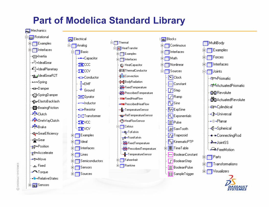
Part of Modelica Standard Library
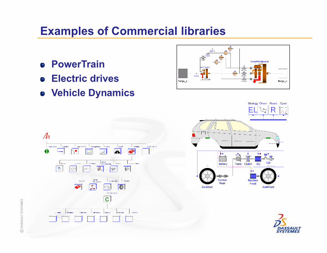
Examples of Commercial libraries
PowerTrain
Electric drives
Vehicle Dynamics

EUROSYSLIB in one slide
Companies Research Institutes & Universities
● Initiated by DS & DLR
● 2.75 Years DurationOct. 2007 – June 2010
● 19 Partners
● 101.5 Person Year effort
● 16 Mill. € total budget
● 8 Sub-Projects
● 32 Work Packages
● 27 Modelica Librariesto be developed
(free + commercial)
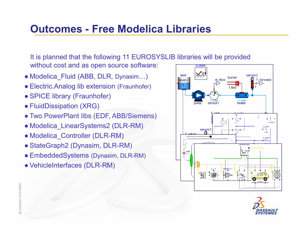
Outcomes - Free Modelica Libraries
It is planned that the following 11 EUROSYSLIB libraries will be provided without cost and as open source software:
● Modelica_Fluid (ABB, DLR, Dynasim…)
● Electric.Analog lib extension (Fraunhofer)
● SPICE library (Fraunhofer)
● FluidDissipation (XRG)
● Two PowerPlant libs (EDF, ABB/Siemens)● Two PowerPlant libs (EDF, ABB/Siemens)
● Modelica_LinearSystems2 (DLR-RM)
● Modelica_Controller (DLR-RM)
● StateGraph2 (Dynasim, DLR-RM)
● EmbeddedSystems (Dynasim, DLR-RM)
● VehicleInterfaces (DLR-RM)
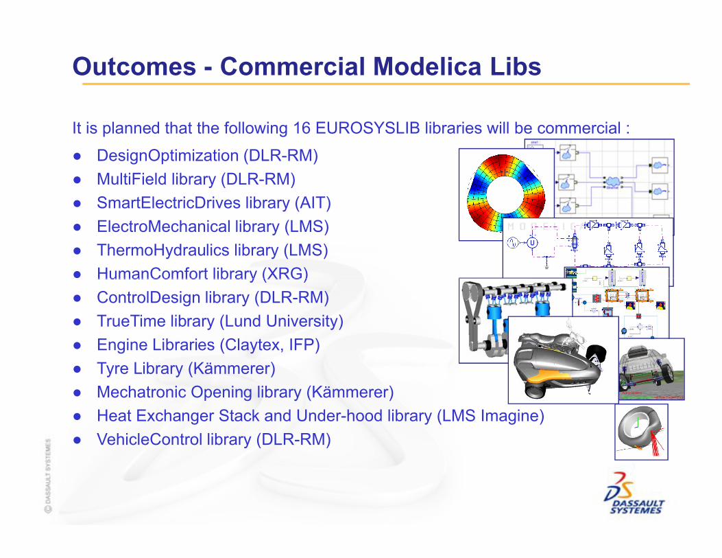
Outcomes - Commercial Modelica Libs
● DesignOptimization (DLR-RM)
● MultiField library (DLR-RM)
● SmartElectricDrives library (AIT)
● ElectroMechanical library (LMS)
● ThermoHydraulics library (LMS)
● HumanComfort library (XRG)
It is planned that the following 16 EUROSYSLIB libraries will be commercial :
● HumanComfort library (XRG)
● ControlDesign library (DLR-RM)
● TrueTime library (Lund University)
● Engine Libraries (Claytex, IFP)
● Tyre Library (Kämmerer)
● Mechatronic Opening library (Kämmerer)
● Heat Exchanger Stack and Under-hood library (LMS Imagine)
● VehicleControl library (DLR-RM)

EUROSYSLIB in the Modelica Conference 2009• Tutorial 3: Simulation of Electrical Machines and Drives Using the Machines and the SmartElectricDrives Lib
• Stream Connectors- Extension of Modelica for Device-Oriented Modeling of Convective Transport Phenomena
• Standardization of Thermo-Fluid Modeling in Modelica.Fluid
• FluidDissipation for Applications a Library for Modelling of Heat Transfer and Pressure Loss in Energy Syst
• Preliminary Design of Electromechanical Actuators with Modelica
• Operator Overloading in Modelica 3.1
• Advanced Simulation of Modelica Models within LMS Imagine.Lab AMESim Environment
• HumanComfort Modelica-Library Thermal Comfort in Buildings and Mobile Applications
• Redundancies in Multibody Systems and Automatic Coupling of CATIA and Modelica
• Investigating the Multibody Dynamics of the Complete Powertrain System
• Modelica for Embedded Systems
18
• Modelica for Embedded Systems
• A New Formalism for Modeling of Reactive and Hybrid Systems
• Improvement of MSL Electrical Analog Library
• News in Dymola
• SPICE3 Modelica Library
• Modelica Libraries for Linear Control Systems
• Linear Analysis Approach for Modelica Models
• TrueTime Network - a Network Simulation Library for Modelica
• Simulation of the Dynamic Behavior of Steam Turbines with Modelica
• The AdvancedMachines Library: Loss Models for Electric Machines
• …
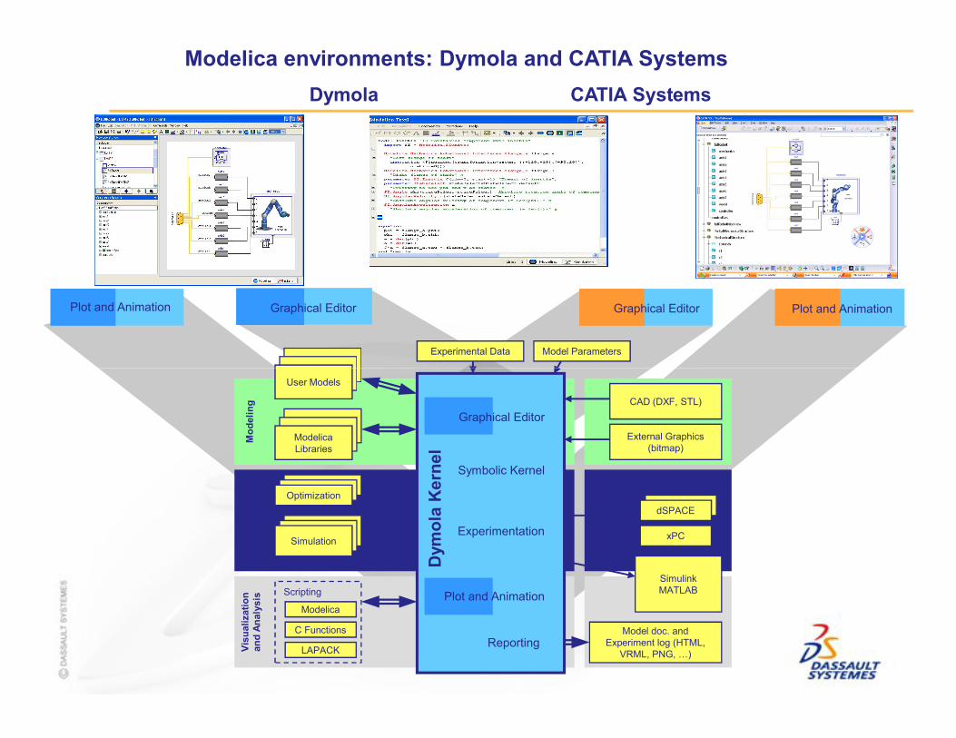
Modelica environments: Dymola and CATIA Systems
Model ParametersExperimental Data
Dymola CATIA Systems
Graphical Editor Graphical Editor Plot and AnimationPlot and Animation
Symbolic Kernel
Experimentation
Reporting
External Graphics (bitmap)
CAD (DXF, STL)
SimulinkMATLAB
Model doc. and Experiment log (HTML,
VRML, PNG, …)
xPC
dSPACE
HIL
Modelica
C Functions
LAPACK
Scripting
Simulation
Optimization
Modelica Libraries
User Models
Mo
del
ing
Sim
ula
tio
nV
isu
aliz
atio
n
and
An
alys
is
Dym
ola
Ker
nel
Graphical Editor
Plot and Animation

CAAV5 DEVCO
N 2006 June 27
th& 28
th-DASSAU
LT SYSTEMES
Virtual testing of system behaviorD
ASSAULT SYSTEM
ES -Page22
Play

Modelica for Embedded Systems
H. Elmqvist1, M. Otter2, D. Henriksson1, B. Thiele2, S.E. Mattsson1
1Dassault Systèmes (Dynasim), Lund, Sweden2DLR - Institut for Robotics and Mechatronics, Oberpfaffenhofen, Germany

Outline
1. Overview
2. Basic Idea
3. Modelica_EmbeddedSystems Library
Slide 24
3. Modelica_EmbeddedSystems Library
4. Modelica Language Extensions
5. Outlook

1. Overview
Modelica is used for advanced controller applications since 2000(using the non-linear plant model in the embedded system). Examples:
courtesy ABB
Slide 25
Boiler startup optimization by ABB(non-linear model predictive control)
Autoland controller by DLR (non-linear dynamic inversion)
Robot vibration control by DLR (non-linear inverse model)
But:Currently only for specialist, with manual coding for production code
Goal:Complete tool chain for model based controllers,especially with non-linear Modelica models in the controller:
non-linear plant model → controller design → target deployment(including cheap microprocessorswithout floating point unit)

Complex control systems in cars
Schäuffele and Zurawka; Automotive Software Engineering; SAE International, 2005
→ Separation of logical design (vehicle functions)
Slide 26
→ Separation of logical design (vehicle functions)and mapping to physical architecture (ECUs)
But:The logical model needs to be partitioned for different applications

Controlled Systems
Flat Logical Model
System Model
Slide 27
Controlled Subsystem
Physical SubsystemControl Subsystem
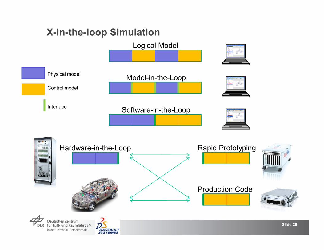
Logical Model
Model-in-the-Loop
Software-in-the-Loop
X-in-the-loop Simulation
Physical model
Control model
Interface
Slide 28
Hardware-in-the-Loop Rapid Prototyping
Production Code

Partitioning of Logical Model
Simulation of logical model variable step size integratorsController: ideal [continuous], synchronous controllers
Model-In-the-Loop (MIL) simulationController – Plant interface modeled (sampled, delays, noise, etc)
Software-In-the-Loop (SIL) simulationController – Plant decomposition, Task – subtask decomposition, [fixed point representation]
Hardware-In-the-Loop (HIL) simulation (real-time)Plant: fixed step size integrators, multi-rate, I/O coupling
Slide 29
Rapid prototyping (real-time)Controller: multi-tasking, I/O channel assignment, bus communication
Production code (real-time)Controller: embedded in ECUs, multi-tasking, [fixed-point representation,] I/O channel assignment, bus communication
Goal: One logical model, many different mappingswithout changing the logical model
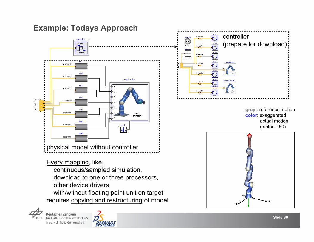
Example: Todays Approach
grey : reference motioncolor: exaggerated
actual motion
controller(prepare for download)
Slide 30
actual motion(factor = 50)
physical model without controller
Every mapping, like,continuous/sampled simulation,download to one or three processors,other device driverswith/without floating point unit on target
requires copying and restructuring of model

Example: New Approach
global controller(e.g. path planning)
Slide 31
Inherit from logical model and define mapping to target system(no change of logical system)
local controllers are in corresponding submodel
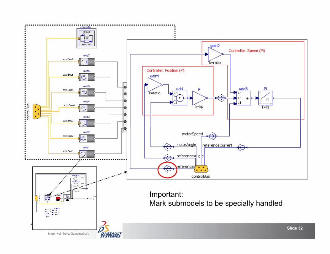
Slide 32
Important:Mark submodels to be specially handled

2. Basic Idea
Ts=5ms Ts=1ms continuous
Slide 33
1. Mark boundaries → Logical model is partitioned in to submodels
2. Make a new model and inherit from logical model
3. Add submodel properties at the boundaries (for input and/or output)
4. Add device drivers at the boundaries (replaceable models)
5. Add target definitions at the boundaries; download selected submodels

Slide 34
Different communication possibilities:
Direct communication (ideal simulation: y = u)
Simulated communication (y = f(u); sampling, delay, value discretization, ...)
Communication between two subtasks(in same task but different sampling; synchronous equations)
Communication between "two tasks", or "task to device" or "device to task"(communication via devices, e.g., shared memory, UDP, CAN-bus, ...;asynchronuous equations)
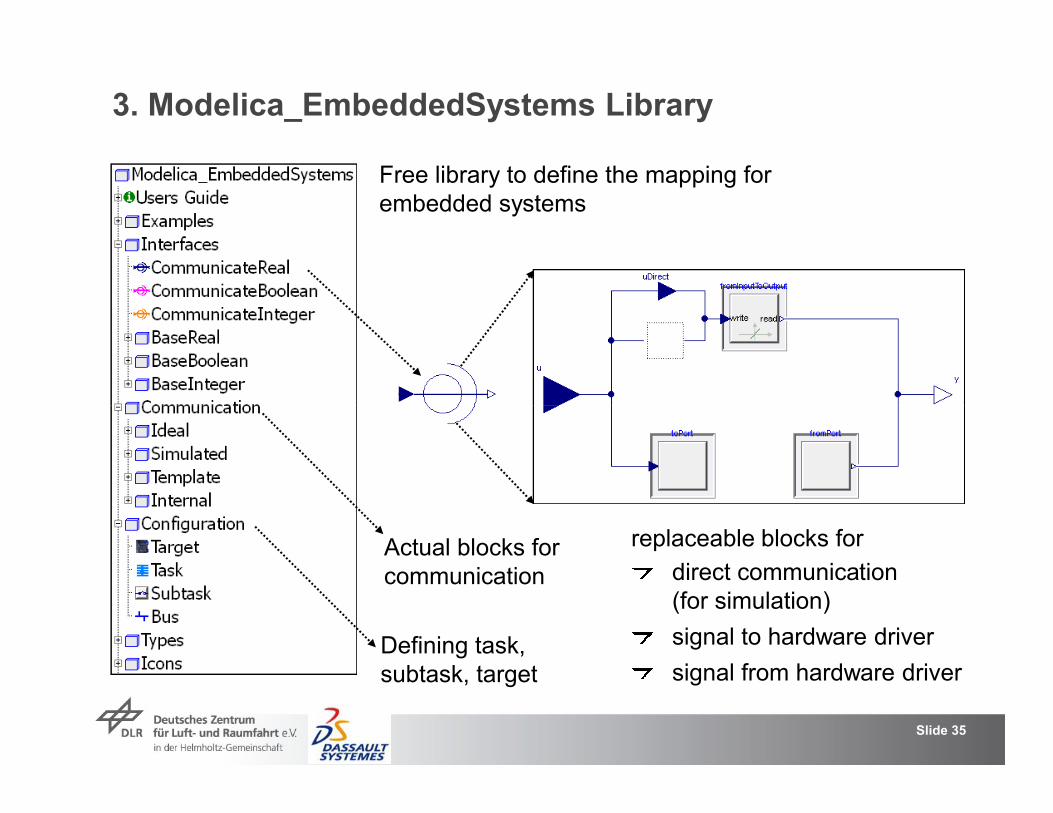
3. Modelica_EmbeddedSystems Library
Free library to define the mapping for embedded systems
Slide 35
replaceable blocks for
direct communication(for simulation)
signal to hardware driver
signal from hardware driver
Actual blocks forcommunication
Defining task, subtask, target
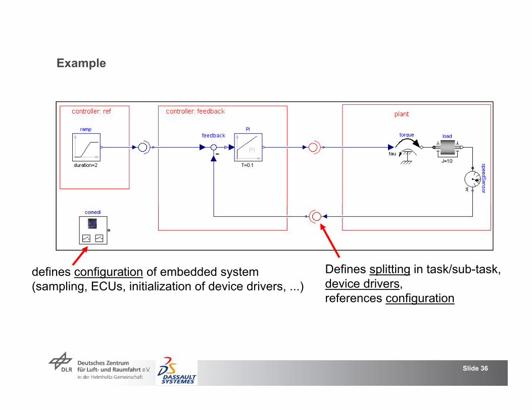
Example
Slide 36
defines configuration of embedded system(sampling, ECUs, initialization of device drivers, ...)
Defines splitting in task/sub-task,device drivers,references configuration

Select the desired communication type. Based on the selection, only the relevant menu items are enabled
Slide 37
here:simulated communicationwith effects likedelay, noise, limitation,quantization, ....
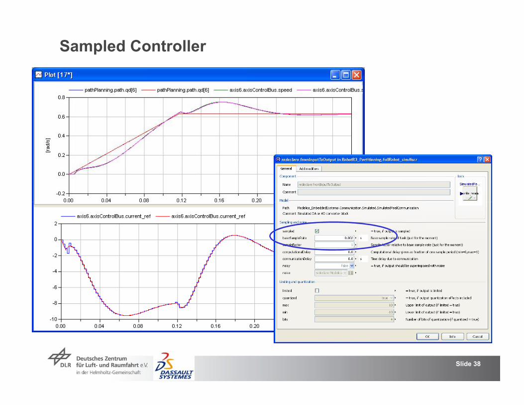
Sampled Controller
Slide 38

Sampled Controller with Delay
Slide 39

Sampled Controller with Input Noise
Slide 40

Sampled Controller with Output Quantization
Slide 41

Slide 42
here:communication between two tasksinput : Writes to hardware (comedi driver)ouput: Reads from hardware (comedi driver)The properties of the task at the input aredefined by config.fastSampler parameters of redeclared
model (comedi device driver)
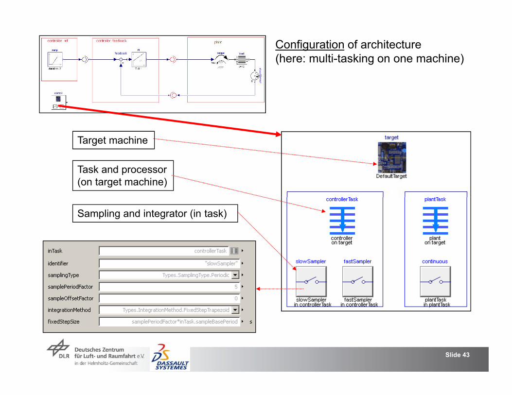
Configuration of architecture(here: multi-tasking on one machine)
Target machine
Task and processor(on target machine)
Slide 43
Sampling and integrator (in task)
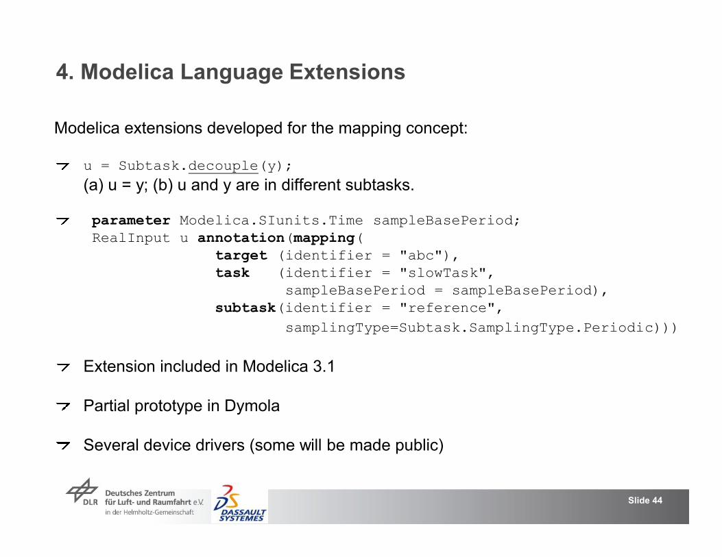
4. Modelica Language Extensions
u = Subtask.decouple(y); (a) u = y; (b) u and y are in different subtasks.
parameter Modelica.SIunits.Time sampleBasePeriod;RealInput u annotation(mapping(
target (identifier = "abc"),task (identifier = "slowTask",
Modelica extensions developed for the mapping concept:
Slide 44
task (identifier = "slowTask", sampleBasePeriod = sampleBasePeriod),
subtask(identifier = "reference",samplingType=Subtask.SamplingType.Periodic)))
Extension included in Modelica 3.1
Partial prototype in Dymola
Several device drivers (some will be made public)

5. Outlook
Full support in Dymola in the near future.
Release of Modelica_EmbeddedSystems, including somefree device drivers (keyboard, game controller, PC speaker, ..)
Near future:
Extension of concept for enabled/triggered tasks
Planned for Modelica 3.2:
Slide 45
Extension of concept for enabled/triggered tasks(currently only for continuous and for periodic tasks)
Improving definition of "timetime" and of "event accuracy":"time" is an integer type of defineable precision per partition (e.g. 1ms)"events" occur only at multiples of base time.
Built-in timer to simplify time event definitions
Define mapping of "Real" to "Integer type"(if no floating point unit on target)
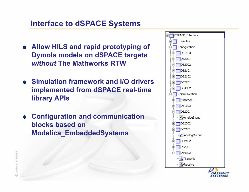
Allow HILS and rapid prototyping of Dymola models on dSPACE targets without The Mathworks RTW
Simulation framework and I/O drivers implemented from dSPACE real-time library APIs
Interface to dSPACE Systems
library APIs
Configuration and communication blocks based on Modelica_EmbeddedSystems

Interface to dSPACE Systems
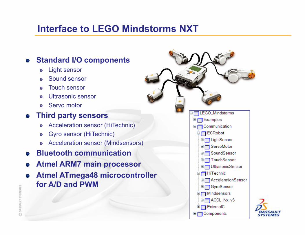
Standard I/O componentsLight sensor
Sound sensor
Touch sensor
Ultrasonic sensor
Servo motor
Third party sensors
Interface to LEGO Mindstorms NXT
Third party sensorsAcceleration sensor (HiTechnic)
Gyro sensor (HiTechnic)
Acceleration sensor (Mindsensors)
Bluetooth communication
Atmel ARM7 main processor
Atmel ATmega48 microcontroller for A/D and PWM
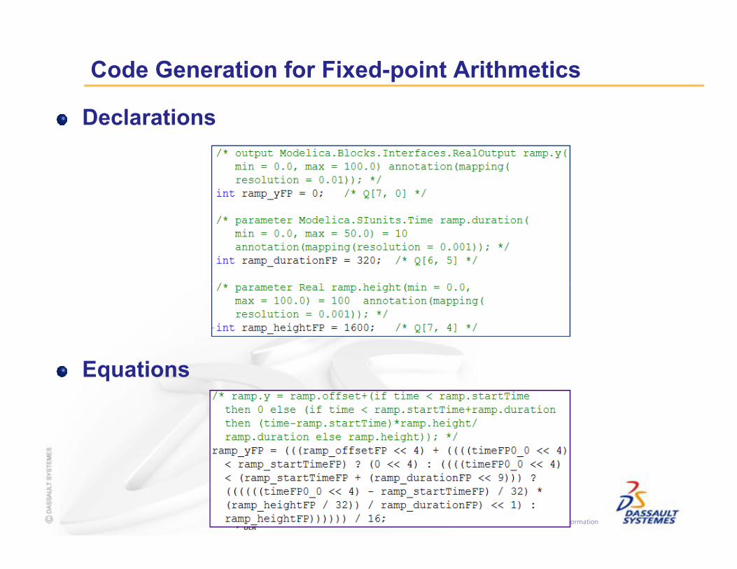
Declarations
Code Generation for Fixed-point Arithmetics
Confidential Information
Equations

Lego Segway control
Confidential Information
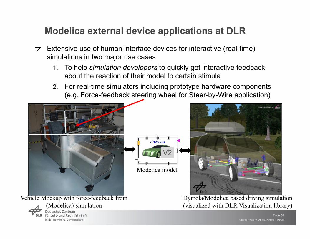
Modelica external device applications at DLR
Extensive use of human interface devices for interactive (real-time) simulations in two major use cases
1. To help simulation developers to quickly get interactive feedback about the reaction of their model to certain stimula
2. For real-time simulators including prototype hardware components (e.g. Force-feedback steering wheel for Steer-by-Wire application)
Folie 54Vortrag > Autor > Dokumentname > Datum
Vehicle Mockup with force-feedback from (Modelica) simulation
Dymola/Modelica based driving simulation (visualized with DLR Visualization library)
Modelica model

Use cases in the simulator development process
Several driver implementation
Hardware device input Blocks
Non-interactive simulation
Interactive model stimula for simulation developers
Force-feedback steering wheel for real-time driving simulation
Folie 55Vortrag > Autor > Dokumentname > Datum
Replaceable driver model
implementation
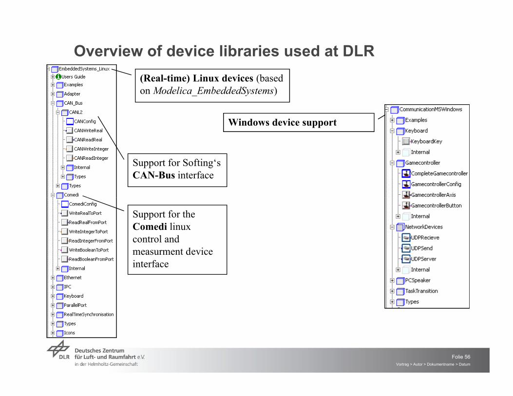
Overview of device libraries used at DLR
Support for Softing‘s CAN-Bus interface
(Real-time) Linux devices (based on Modelica_EmbeddedSystems)
Windows device support
Folie 56Vortrag > Autor > Dokumentname > Datum
Support for the Comedi linux control and measurment device interface
A New Formalism for Modeling of Reactive and Hybrid Systems
Martin Otter
Martin Malmheden
Hilding Elmqvist
Sven Erik MattssonSven Erik Mattsson
Charlotta Johnsson
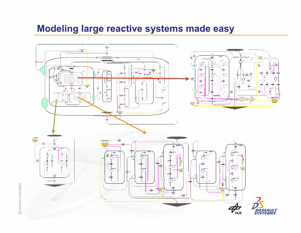
Modeling large reactive systems made easy
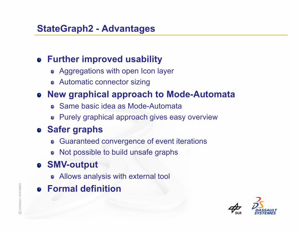
StateGraph2 - Advantages
Further improved usabilityAggregations with open Icon layer
Automatic connector sizing
New graphical approach to Mode-AutomataSame basic idea as Mode-Automata
Purely graphical approach gives easy overviewPurely graphical approach gives easy overview
Safer graphsGuaranteed convergence of event iterations
Not possible to build unsafe graphs
SMV-outputAllows analysis with external tool
Formal definition
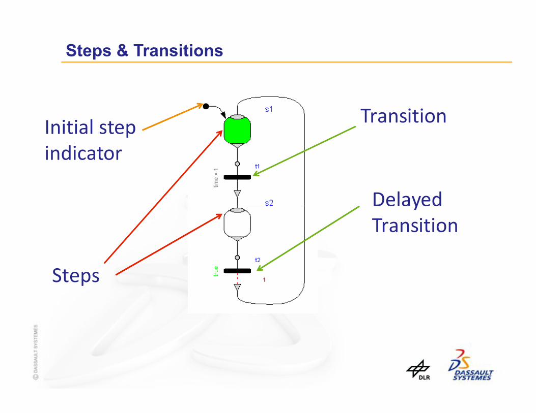
Steps & Transitions
Initial step indicator
Transition
Delayed
Steps
DelayedTransition

Steps & Transitions are implemented in pure Modelica

The Parallel Component cont’d
Parallel branchingEvery branch must be connected to the entry port
Synchronization by connecting branches to the exit port
Requires inport and outport
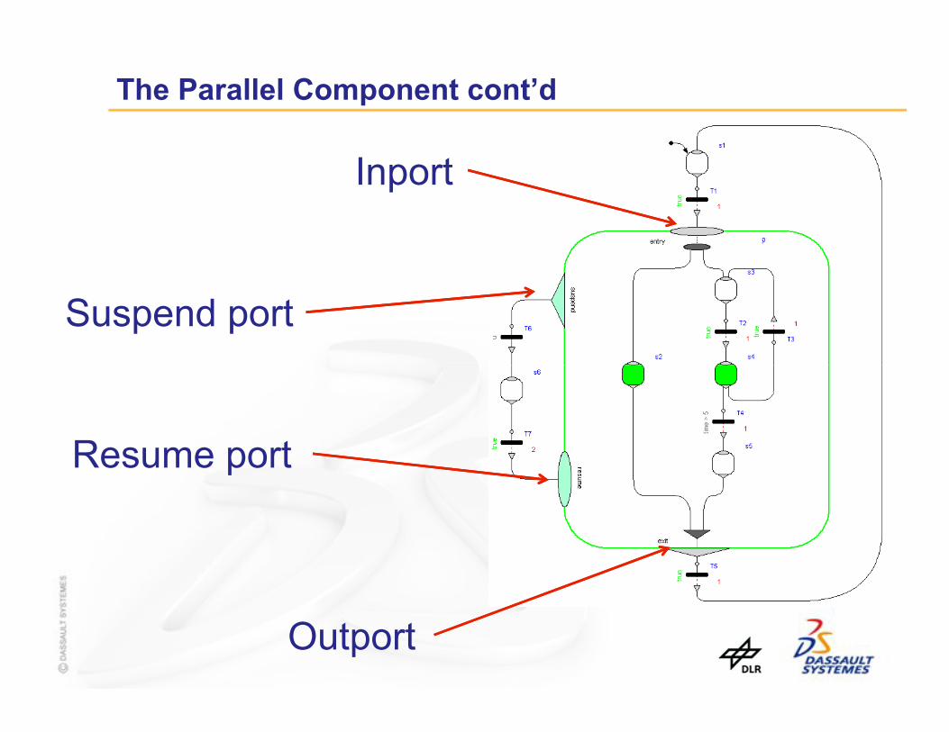
The Parallel Component cont’d
Inport
Suspend port
Resume port
Outport

Hierarchical Hybrid System – Tank example
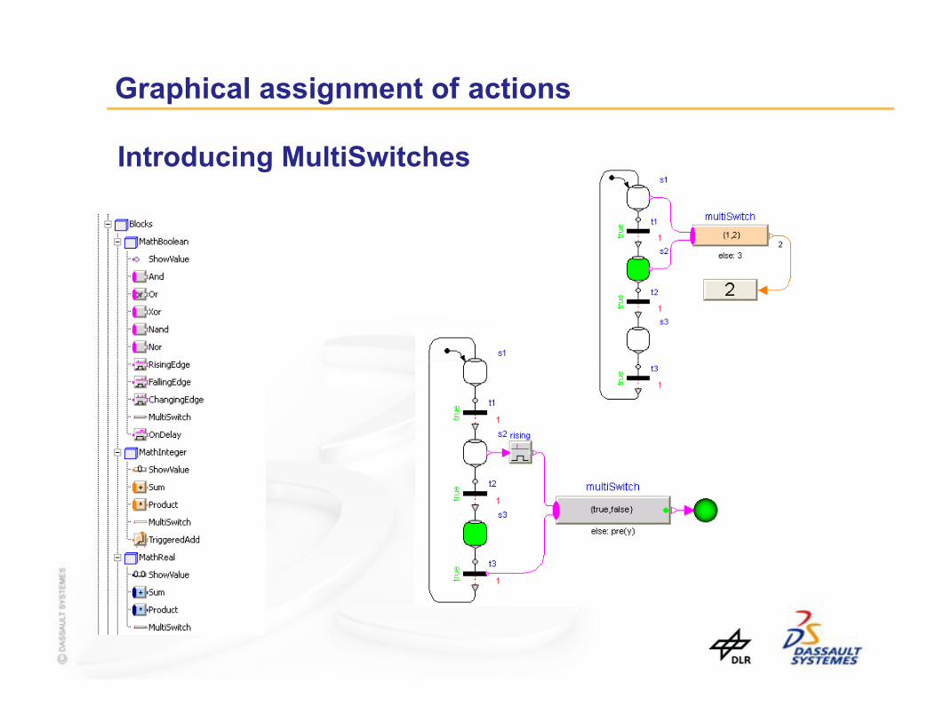
Graphical assignment of actions
Introducing MultiSwitches
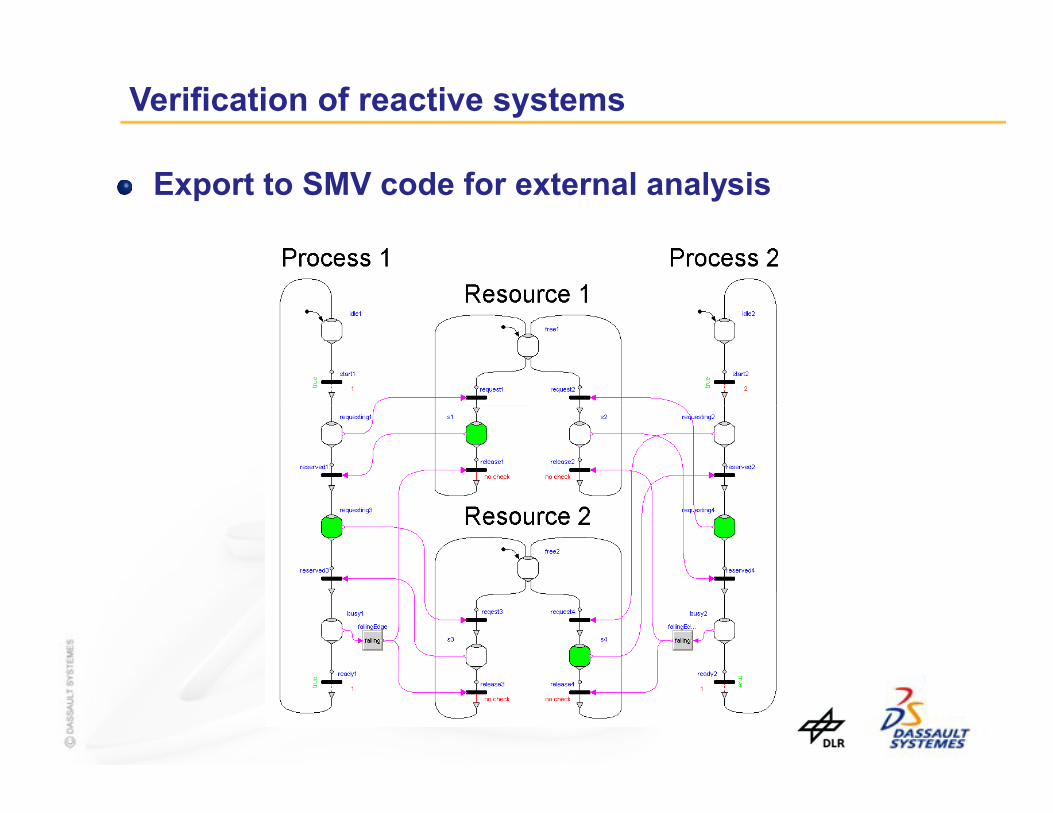
Verification of reactive systems
Export to SMV code for external analysis
Summary
User friendly
Improved graphical approach to variable assignment
Safe – not possible to make dangerous graphsgraphs
Flexible
Allows external analysis of graph structure
Functional Mockup Interface – Overview
Martin Otter (DLR-RM)Torsten Blochwitz (ITI)Torsten Blochwitz (ITI)
Hilding Elmqvist (Dassault Systèmes – Dynasim)
Andreas Junghanns (QTronic)
Jakob Mauss (QTronic)
Hans Olsson (Dassault Systèmes – Dynasim)

Contents
1. Functional Mockup Interface – Goals
2. FMI - Distribution of Model
3. FMI - Model Description Schema
4. FMI - Model Interface
Functional Mockup Interface - Overview > Jan. 25 2010 > Slide 77
4. FMI - Model Interface
5. Tool Support for FMI
6. Comparison with SIMULINK S-Function Interface
7. Outlook
8. Acknowledgements

1. Functional Mockup Interface (FMI) – Goals
Overall goal of FMI in MODELISAR
... for (alphabetically ordered)Concrete goal of FMI in MODELISAR
Software/Model/Hardware-in-the-Loop, of physical models andof AUTOSAR controller modelsfrom different vendors forautomotive applications withdifferent levels of detail.
Functional Mockup Interface - Overview > Jan. 25 2010 > Slide 78
... for (alphabetically ordered)AMESim (Modelica, hydraulic)Dymola (Modelica)EXITE (co-simulation environment) Silver (co-simulation environment)SIMPACK (multi-body)SimulationX (Modelica)SIMULINK
Open Standard
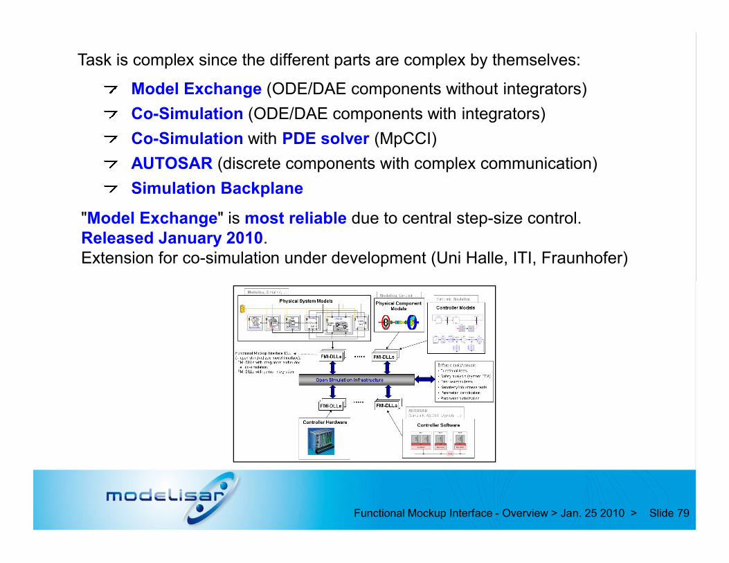
Task is complex since the different parts are complex by themselves:
Model Exchange (ODE/DAE components without integrators)
Co-Simulation (ODE/DAE components with integrators)
Co-Simulation with PDE solver (MpCCI)
AUTOSAR (discrete components with complex communication)
Simulation Backplane
"Model Exchange" is most reliable due to central step-size control.Released January 2010.Extension for co-simulation under development (Uni Halle, ITI, Fraunhofer)
Functional Mockup Interface - Overview > Jan. 25 2010 > Slide 79
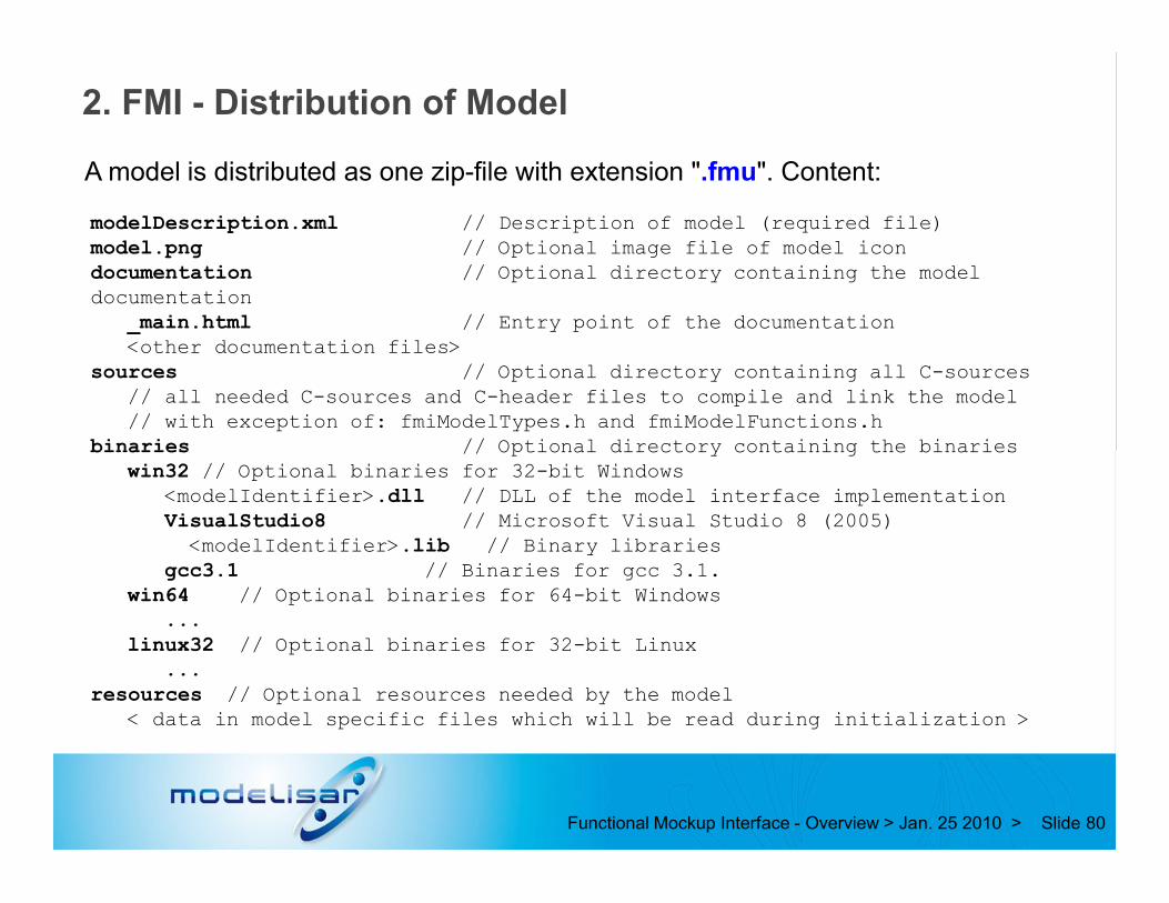
2. FMI - Distribution of Model
A model is distributed as one zip-file with extension ".fmu". Content:
modelDescription.xml // Description of model (required file) model.png // Optional image file of model icondocumentation // Optional directory containing the model documentation
_main.html // Entry point of the documentation <other documentation files>
sources // Optional directory containing all C-sources // all needed C-sources and C-header files to compile and link the model// with exception of: fmiModelTypes.h and fmiModelFunctions.h
binaries // Optional directory containing the binaries
Functional Mockup Interface - Overview > Jan. 25 2010 > Slide 80
binaries // Optional directory containing the binaries win32 // Optional binaries for 32-bit Windows
<modelIdentifier>.dll // DLL of the model interface implementationVisualStudio8 // Microsoft Visual Studio 8 (2005)<modelIdentifier>.lib // Binary libraries
gcc3.1 // Binaries for gcc 3.1.win64 // Optional binaries for 64-bit Windows
...linux32 // Optional binaries for 32-bit Linux
...resources // Optional resources needed by the model
< data in model specific files which will be read during initialization >
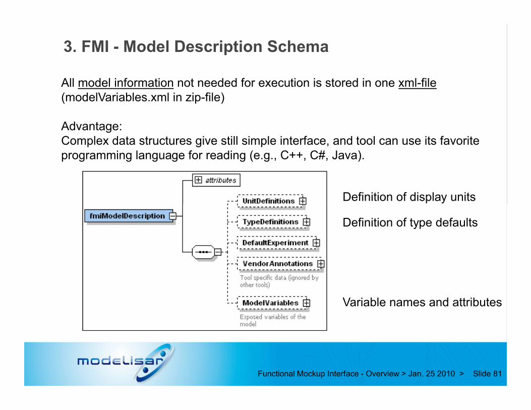
3. FMI - Model Description Schema
All model information not needed for execution is stored in one xml-file(modelVariables.xml in zip-file)
Advantage:Complex data structures give still simple interface, and tool can use its favorite programming language for reading (e.g., C++, C#, Java).
Definition of display units
Functional Mockup Interface - Overview > Jan. 25 2010 > Slide 81
Variable names and attributes
Definition of type defaults

Attributes of ModelVariables
unique name
handle to identifyvariable in C-functions
Functional Mockup Interface - Overview > Jan. 25 2010 > Slide 84
...

Data types allow to store all (relevant) Modelica attributes.Defaults from TypeDefinitions
Functional Mockup Interface - Overview > Jan. 25 2010 > Slide 85
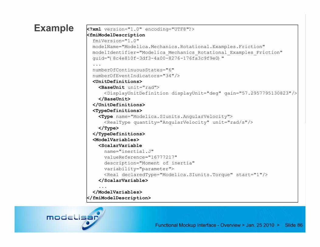
Example <?xml version="1.0" encoding="UTF8"?><fmiModelDescription
fmiVersion="1.0"modelName="Modelica.Mechanics.Rotational.Examples.Friction"modelIdentifier="Modelica_Mechanics_Rotational_Examples_Friction"guid="{8c4e810f-3df3-4a00-8276-176fa3c9f9e0}"...numberOfContinuousStates="6"numberOfEventIndicators="34"/><UnitDefinitions>
<BaseUnit unit="rad"><DisplayUnitDefinition displayUnit="deg" gain="57.2957795130823"/>
</BaseUnit></UnitDefinitions><TypeDefinitions>
<Type name="Modelica.SIunits.AngularVelocity"><RealType quantity="AngularVelocity" unit="rad/s"/>
Functional Mockup Interface - Overview > Jan. 25 2010 > Slide 86
<RealType quantity="AngularVelocity" unit="rad/s"/></Type>
</TypeDefinitions><ModelVariables>
<ScalarVariablename="inertia1.J"valueReference="16777217"description="Moment of inertia"variability="parameter"><Real declaredType="Modelica.SIunits.Torque" start="1"/>
</ScalarVariable>...
</ModelVariables></fmiModelDescription>

4. FMI - Model Interface
Functional Mockup Interface - Overview > Jan. 25 2010 > Slide 87

Functional Mockup Interface - Overview > Jan. 25 2010 > Slide 88
// Set input argumentsfmiSetTime(m, time);fmiSetReal(m, id_u1, u1, nu1);fmiSetContinuousStates(m, x, nx);
// Get resultsfmiGetContinuousStates(m, derx, nx);fmiGetEventIndicators (m, z, nz);
Example:
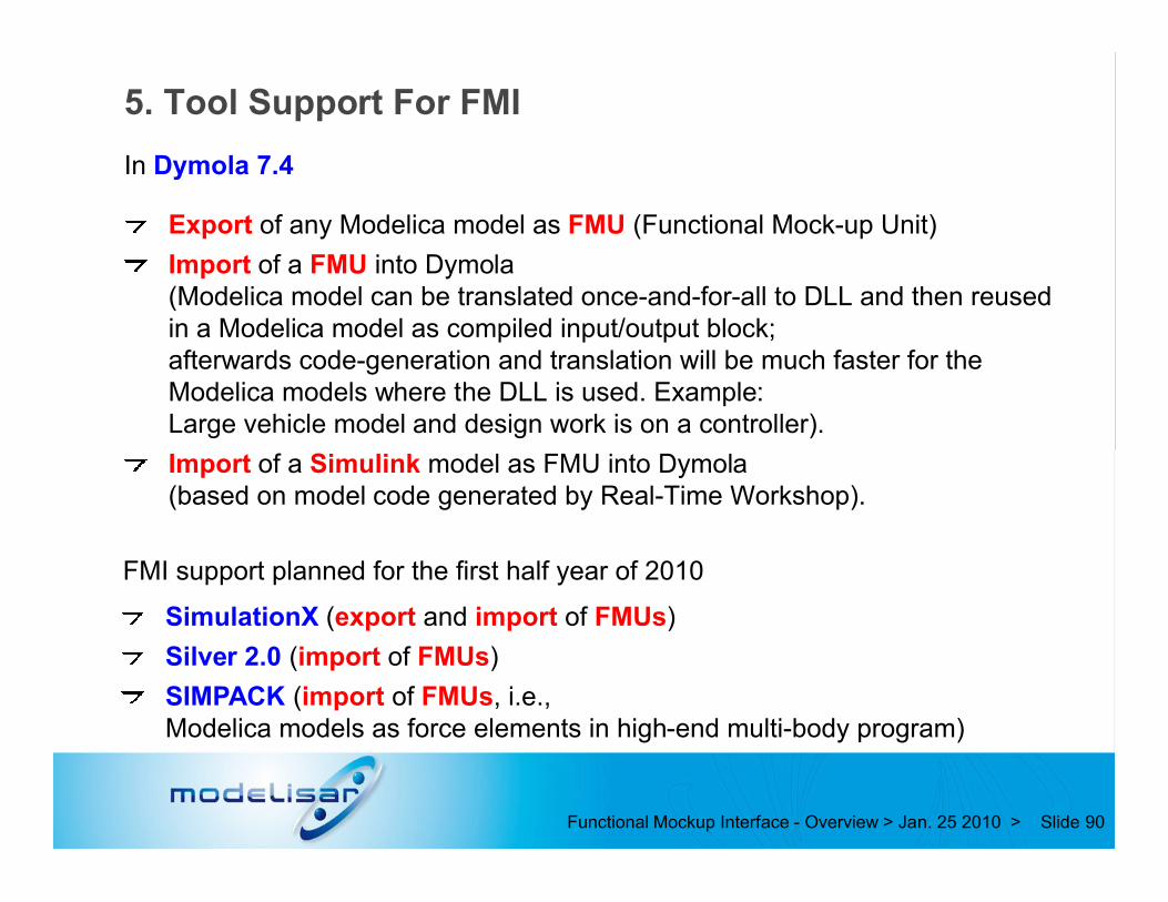
5. Tool Support For FMI
Export of any Modelica model as FMU (Functional Mock-up Unit)
Import of a FMU into Dymola(Modelica model can be translated once-and-for-all to DLL and then reused in a Modelica model as compiled input/output block;afterwards code-generation and translation will be much faster for the Modelica models where the DLL is used. Example:Large vehicle model and design work is on a controller).
Import of a Simulink model as FMU into Dymola
In Dymola 7.4
Functional Mockup Interface - Overview > Jan. 25 2010 > Slide 90
Import of a Simulink model as FMU into Dymola(based on model code generated by Real-Time Workshop).
SimulationX (export and import of FMUs)
Silver 2.0 (import of FMUs)
SIMPACK (import of FMUs, i.e., Modelica models as force elements in high-end multi-body program)
FMI support planned for the first half year of 2010

7. Outlook
"FMI for Model Exchange" released
"FMI for Co-Simulation" in a good stage. Will be released in first half year.(support for: extrapolation/interpolation of interface variables,variable communication step-size, re-doing a step → step-size control possible).
"FMI for Model Exchange" will be further developer. A lot of requirements available, such as:
Sparse Jacobian
Functional Mockup Interface - Overview > Jan. 25 2010 > Slide 95
Sparse Jacobian
Direct support for arrays and records in xml schema
Improved sample time definition (for embedded systems)
Online changeable parameters
Saving/restoring model state
...
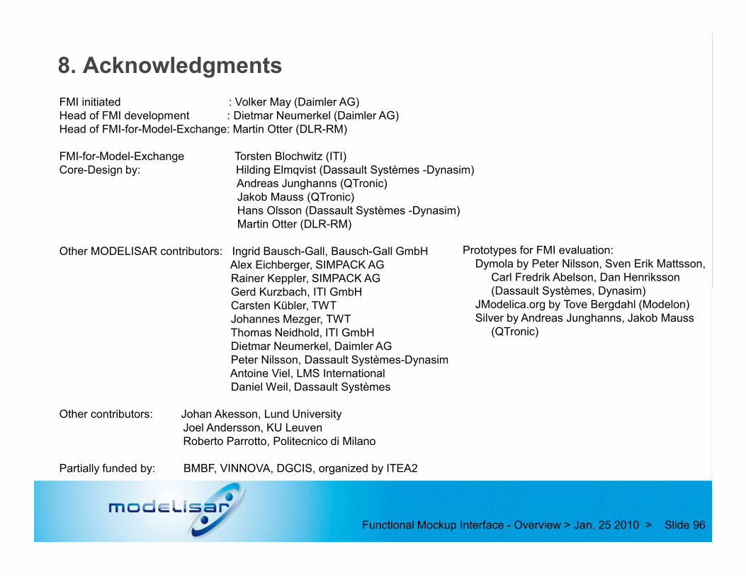
8. Acknowledgments
FMI initiated : Volker May (Daimler AG)Head of FMI development : Dietmar Neumerkel (Daimler AG)Head of FMI-for-Model-Exchange: Martin Otter (DLR-RM)
FMI-for-Model-Exchange Torsten Blochwitz (ITI)Core-Design by: Hilding Elmqvist (Dassault Systèmes -Dynasim)
Andreas Junghanns (QTronic)Jakob Mauss (QTronic)Hans Olsson (Dassault Systèmes -Dynasim)Martin Otter (DLR-RM)
Other MODELISAR contributors: Ingrid Bausch-Gall, Bausch-Gall GmbHAlex Eichberger, SIMPACK AGRainer Keppler, SIMPACK AGGerd Kurzbach, ITI GmbH
Prototypes for FMI evaluation:Dymola by Peter Nilsson, Sven Erik Mattsson,
Carl Fredrik Abelson, Dan Henriksson(Dassault Systèmes, Dynasim)
Functional Mockup Interface - Overview > Jan. 25 2010 > Slide 96
Gerd Kurzbach, ITI GmbHCarsten Kübler, TWTJohannes Mezger, TWTThomas Neidhold, ITI GmbH Dietmar Neumerkel, Daimler AGPeter Nilsson, Dassault Systèmes-DynasimAntoine Viel, LMS InternationalDaniel Weil, Dassault Systèmes
Other contributors: Johan Akesson, Lund UniversityJoel Andersson, KU LeuvenRoberto Parrotto, Politecnico di Milano
Partially funded by: BMBF, VINNOVA, DGCIS, organized by ITEA2
(Dassault Systèmes, Dynasim) JModelica.org by Tove Bergdahl (Modelon)Silver by Andreas Junghanns, Jakob Mauss
(QTronic)

Outlook
Modelica scope extended to code generation for embedded targets
Designed to be flexible enough to allow reuse of logical model for many X-In-the-Loop scenarios
Integrating the solutions
Utilize in larger projectsUtilize in larger projects