New Mechanism Used in Standing Wheelchair - diva …829471/FULLTEXT01.pdf · New Mechanism Used in...
73
in cooperation with Tianxiang Mo Yufeng Sun Yonghao Yang Department of Mechanical Engineering Blekinge Institute of Technology Karlskrona Sweden 2014 Bachelor of Science Thesis in Mechanical Engineering New Mechanism Used in Standing Wheelchair
Transcript of New Mechanism Used in Standing Wheelchair - diva …829471/FULLTEXT01.pdf · New Mechanism Used in...
in cooperation with
Tianxiang Mo Yufeng Sun
Yonghao Yang
Department of Mechanical Engineering Blekinge Institute of Technology
Karlskrona Sweden
2014
Bachelor of Science Thesis in Mechanical Engineering
New Mechanism Used in Standing Wheelchair

2
Abstract
It is inevitable for any country to have people with disabilities or have trouble with standing up, especially arthritis patients. The most common used devices for disabled people are wheelchairs. What’s more, the life quality of disabled people and patients has caught attention by society. Modernized wheelchair has become a popular engineering challenge for decades.
We aimed to design a new mechanical system in wheelchair to help people stand up, this mechanism should be safer, simpler in structure, less power consuming and more economic.
A parallelogram structure was designed for wheelchair to fit the natural human standing posture. Springs installed at two nonadjacent vertexes can accumulate energy. A motor with less power and cheaper prices is reasonable, energy-saving and easily provide the power to lift up.
After research and calculation, this parallelogram structure reduced almost 45% power compared with pure motor drive one. And the effort of every part can well support human’s body to form a natural and comfortable process.
The standing wheelchair we designed may help people with disability to surge self-esteem; reach objects placed high, deliver speech on podium. By the way, it’s boring for a person to sit for long time.
Keywords: Mechanical automatic standing system, ergonomics, elder and people with
disability, wheelchair, CAD

3
Acknowledgements
We would like to show our gratitude to our supervisor Md. Shafiqul Islam, he taught us advanced Inventor 2014 skills and give us various beneficial suggestions. Examiner Dr. Mats Walter and teacher Dr. Sharon Kao-Walter helped us to investigate in a real disability welfare company as well as comments and encouragements. It would be problematic for us to complete this report without their help.
A special thanks to Prof. Wlodek Kulesza. He pays great attention to our fresh thesis, taught us writing a thesis in professional format and how to capture what community need.
Finally, we would like to recognize our former university teachers, the fundamental knowledge is indispensable in this report.
Tianxiang Mo Yufeng Sun
Yonghao Yang
4
Contents
Abstract ........................................................................................ 2 Acknowledgements ...................................................................... 3 Contents ....................................................................................... 4 List of figures ............................................................................... 6 List of tables ................................................................................. 6 List of symbols ............................................................................. 8 List of acronyms ........................................................................ 10 1 Chapter: Introduction ............................................................ 12 2 Chapter: Survey of related work ........................................... 13 3 Chapter: Problem statement, objectives and main contribution ............................................................................... 17 4 Chapter: Solution ................................................................... 17
4.1 Different solutions.............................................................................. 18 4.1.1 Standing wheelchair using the principle of folding chairs ............ 18 4.1.2 Standing wheelchair using hydraulic control system .................... 19 4.1.3 Standing wheelchair using parallelogram ..................................... 20
4.2 Comparison and results ...................................................................... 21 4.2.1 Comparison ................................................................................. 21
4.2.1.1 Folding chair principle .......................................................... 21 4.2.1.2 Hydraulic controlling wheelchair .......................................... 22 4.2.1.3 Wheel chair with parallelogram ............................................ 23
4.2.2 Results ........................................................................................ 24 4.3 Design of the best solution ................................................................. 24
4.3.1 The flowchart of wheelchair ........................................................ 25 4.3.2 Modeling ..................................................................................... 26
4.3.2.1 Back support (top) ................................................................ 27 4.3.2.2 Transformable parallelogram (middle) .................................. 30 4.3.2.3 Base (bottom) ....................................................................... 32 4.3.2.4 Displacement restrict trigger ................................................. 33 4.3.2.5 Spring lock ........................................................................... 33 4.3.2.6 Motor transmission design .................................................... 35
5 Chapter: Calculation ............................................................. 37

5
5.1 Deformation of the base...................................................................... 37 5.2 Spring design...................................................................................... 42 5.3 Stability calculation ............................................................................ 46 5.4 Motor selection................................................................................... 50 5.5 Stress analysis by using FEM ............................................................. 52
6 Chapter: Controlling system ................................................. 58 6.1 Controller selection ............................................................................ 60 6.2 Stepper motor driver selection ............................................................ 60 6.3 Power supply selection ....................................................................... 61
7 Chapter: Conclusion and future work .................................. 63 7.1 Conclusion ......................................................................................... 64 7.2 Future work ........................................................................................ 64
Reference ................................................................................... 65 Appendix: The drawings of main components ........................ 68

6
List of figures
Figure 2-1. Manually operable standing wheelchair [2] ................................ 14 Figure 2-2. Electrical controlling [3] ............................................................ 15 Figure 2-3. Another electrically controlled wheelchair [4]............................ 16 Figure 2-4. Make person lie down [4] .......................................................... 16 Figure 4-1. Standing wheelchair using the principle of folding chairs........... 19 Figure 4-2. Standing wheelchair using hydraulic control system .................. 20 Figure 4-3. Standing wheelchair using parallelogram ................................... 21 Figure 4-4. Main view of final modelling ..................................................... 25 Figure 4-5. Flow char of actions performed during standing up and sitting down............................................................................................................ 26 Figure 4-6. Assembly drawing of top part in wheelchair .............................. 27 Figure 4-7. Schematic diagram of how does the back support work ............. 28 Figure 4-8. Determine the angle when person start to stand up ..................... 28 Figure 4-9. The angle of final standing position ........................................... 29 Figure 4-10. Schematic diagram of how does elastic belt work .................... 30 Figure 4-11. Assembly drawing of middle part in wheelchair ....................... 30 Figure 4-12. The demonstration of the parallelogram ................................... 31 Figure 4-13. The change of the centre of gravity when person want to stand up .................................................................................................................... 32 Figure 4-14. Assembly drawing of bottom part in wheelchair ...................... 32 Figure 4-15. Displacement restrict trigger .................................................... 33 Figure 4-16. Main view of our spring lock ................................................... 34 Figure 4-17. Spring lock locks the whole standing system............................ 34 Figure 4-18. Chain transmission................................................................... 35 Figure 4-19. Moving motor .......................................................................... 36 Figure 5-1. Parallelogram structure .............................................................. 37 Figure 5-2. Nodes, elements and degrees of freedom ................................... 38 Figure 5-3. Stress analysis (First time design, 60°) ....................................... 42 Figure 5-4. Stress analysis (First time design, 0°) ......................................... 43 Figure 5-5. Stress analysis (Second time design, 60°)................................... 45 Figure 5-6. Stress analysis (Second time design, 0°) .................................... 45 Figure 5-7. Body size distribution in our wheelchair .................................... 47 Figure 5-8. Body mass distribution [10] ....................................................... 48 Figure 5-9. Stress analysis in stability calculation ........................................ 49 Figure 5-10. Anti-dumping wheels ............................................................... 50 Figure 5-11. Schematic of transmission........................................................ 50 Figure 5-12. Parameter of motor [11] ........................................................... 52

7
Figure 5-13. The maximum result of Mises when the thickness of seat is 10mm...........................................................................................................53 Figure 5-14. The maximum result of displacement when the thickness of seat is 10mm .......................................................................................................53 Figure 5-15. The result of safety factor when the thickness of seat is 10mm .54 Figure 5-16. The maximum result of Mises when the thickness of seat is 15mm...........................................................................................................54 Figure 5-17. The maximum result of displacement when the thickness of seat is 15mm .......................................................................................................55 Figure 5-18. The result of safety factor when the thickness of seat is 15mm .55 Figure 5-19. The maximum Mises of parallelogram .....................................56 Figure 5-20. The maximum displacement of parallelogram ..........................57 Figure 6-1. Control buttons ..........................................................................58 Figure 6-2. The schematic of system [14] .....................................................59 Figure 6-3. MCS-51 core [15] ......................................................................60 Figure 6-4. DQ860MA driver [16] ...............................................................60 Figure 6-5. The parameters of driver [16] .....................................................61 Figure 6-6. JSS-120-24 Switch Power Supply [17] .......................................61 Figure 6-7. The parameters of JSS-120-24 Switch Power Supply [17] ..........62

8
List of tables
Table 4-1. Assessment ................................................................................. 24 Table 5-1. Connectivity among elements ..................................................... 38 Table 5-2. Coordinates and values of l and m for each element .................... 39 Table 5-3. Final selection of the spring parameters....................................... 46 Table 5-4. Parameter of two gears ................................................................ 51 Table 6-1. The price list of controlling system ............................................. 63

9
List of symbols
Symbol Quantity Unit E Young’s modulus [ Pa ] G People’s weight [ N ] kx Local stiffness of element x [ N/m ] Q Deformation displacement [ m ] x1 Length of spring when angle is 60 [ m ] Fs1 Force of total spring when angle is 60 [ N ] Fes1 Force of each spring when angle is 60 [ N ] x2 Length of spring when angle is 0 [ m ] Fs2 Force of total spring when angle is 0 [ N ] Fes2 Force of each spring when angle is 0 [ N ] k Stiffness coefficient of spring [ N/m ] Ga Rigidity modulus of wire [ N/m ] d Diameter of wire [ mm ] N Total turns of spring Nc Effective turns of spring Dm Middle diameter [ mm ] Fu Force of upper body [ N ] Ft Force of thigh link [ N ] Fsf Force of shank link and foot link [ N ] Mu The moment of upper body [ Nm ] Mt The moment of thigh link [ Nm ] Msf The moment of shank link and foot link [ Nm ] θ Lifting angle of seat [ ] F Force provided by motor [ N ] T1 The torque of small gear [ Nm ] T2 The torque of big gear [ Nm ] P1 The power of small gear [ w ] P2 The power of big gear [ w ] ω1 Angular velocity of small gear [ rad/s ] ω2 Angular velocity of big gear [ rad/s ] r1 Radius of small gear [ m ] r2 Radius of big gear [ m ] d1 Diameter of small gear [ mm ] d2 Diameter of big gear [ mm ] m Modulus of gear [ mm ]

10
z1 Tooth of small gear z2 Tooth of big gear

11
List of acronyms
Acronym Unfolding FEM Finite Element Method
PWM Pulse Width Modulation
DC Direct Current AC Alternating Current
PC Personal Computer
CAD Computer Aided Design

12
1 Chapter: Introduction
With the development of Swedish society, many people and organizations pay more attention to life quality of people with disabilities. Wheelchairs play irreplaceable role in aiding people for few decades. Therefore, the upgrade and refreshment of wheelchair function and mechanical structure will be a priority for community and welfare institution. Wheelchair has a variety range of styles in current market. Aluminium, steel and lightweight solid are the common materials in manufacturing. It can also be classified by functions: manually operable wheelchairs and Electrical controlling wheelchairs. Nowadays, standing wheelchair is developed as a new kind of wheelchair. If the patient wants to reach a higher position or move from chair to bed, even deliver a speech at podium, he or she will be willing to form a standing up process. At this time, standing wheelchair will help him or her to accomplish this goal.
We searched about most common types of standing wheelchair on Internet. We found most pure mechanical wheelchair require arm force when achieving standing up motion. Compared to this kind of wheelchair, electrical wheelchair is more advanced, but most of electrical wheelchairs do not use smart structure to aid standing, which has complex controller system and waste of energy. Furthermore, we think all standing wheelchairs do not comply with the provisions of the people regular standing postures. Thus, we want to design our own standing wheelchair to solve such problems. We want to combine mechanical and electrical components in our wheelchair to improve the standing wheelchair. The wheelchair we designed will use less electrical energy to help people standing, nevertheless it will be as convenient as eclectic wheelchair.
We use Inventor 2014 [1] to model our solution. It enables our design to be more intuitive and able to check the feasibility of our design. Then, we do some hand calculations to design key components of the structure. Finally we do stress analysis by Stress Analysis Environment in Inventor to make sure that our wheelchair can bear properly. This function can examine material yield stress withstand maximum stress, and ensure the deformation of material is in an acceptable extent. Through these works, we designed our own wheelchair, improved the solution of major problems which mentioned above. We consider our wheelchair as simple structure as traditional standing

13
wheelchair, easily control as electrical wheelchair, but saving more energy than electrical one which has already been developed.

14
2 Chapter: Survey of related work
We searched some related samples on the Internet and publication database, we found that aid standing wheelchair become more intelligent. Through using standing wheelchair, disabilities can easily stand up.
Our group started to do research on first edition of standing wheelchair. One of them is [2] manually operable standing wheelchair, published in 2005, see Figure 2-1. The advantage of this kind of wheelchair is simplicity in structure. Position of seat is fixed on the horizontal plane, but movable in vertical by installing back on a rod. This wheelchair uses pure mechanical method to aid standing up. We think this method of easiest way to achieve our goal. Because of the simple structure, this wheelchair has some problem when it works. The wheelchair is operated manually, which means disabled people must have strong forearms to force the wheelchair work. If patient is weak in stamina or have problems in their arms, they cannot operate this kind of wheelchair.
Figure 2-1. Manually operable standing wheelchair [2]
15
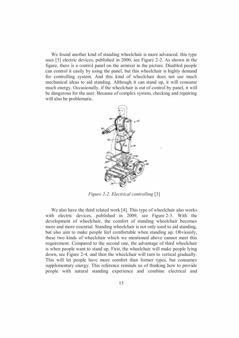
We found another kind of standing wheelchair is more advanced. this type uses [3] electric devices, published in 2000, see Figure 2-2. As shown in the figure, there is a control panel on the armrest in the picture. Disabled people can control it easily by using the panel, but this wheelchair is highly demand for controlling system. And this kind of wheelchair does not use much mechanical ideas to aid standing. Although it can stand up, it will consume much energy. Occasionally, if the wheelchair is out of control by panel, it will be dangerous for the user. Because of complex system, checking and repairing will also be problematic.
Figure 2-2. Electrical controlling [3]
We also have the third related work [4]. This type of wheelchair also works
with electric devices, published in 2009, see Figure 2-3. With the development of wheelchair, the comfort of standing wheelchair becomes more and more essential. Standing wheelchair is not only used to aid standing, but also aim to make people feel comfortable when standing up. Obviously, these two kinds of wheelchair which we mentioned above cannot meet this requirement. Compared to the second one, the advantage of third wheelchair is when people want to stand up. First, the wheelchair will make people lying down, see Figure 2-4, and then the wheelchair will turn to vertical gradually. This will let people have more comfort than former types, but consumes supplementary energy. This reference reminds us of thinking how to provide people with natural standing experience and combine electrical and

16
mechanical to save energy as well (keep balance between comfort and energy consumption).
Figure 2-3. Another electrically controlled wheelchair [4]
Figure 2-4. Make person lie down [4]
17
3 Chapter: Problem statement, objectives and main contribution
The objective of this thesis is to design an automatic mechanical wheelchair. This wheelchair helps those who are elder, weak or patients in rehabilitation.
The wheelchair we designed will overcome difficulties as follow. The first is designing structures that can perform a natural human standing behaviour. Next is to determine the energy system that provides the power to change the form of the wheelchair operational part. Third is to briefly design the controlling system to monitor the wheelchair’s working.
Main contribution of this thesis is to design a new mechanical structure. The wheelchair can reform automatically and support the costumer standing up. The standing position fits the human standing posture. This kind of wheelchair will use less electrical power. Compared to traditional electrical wheelchair, it can save energy and work stable as well. Components we used are available in the market.
18
4 Chapter: Solution
4.1 Different solutions
4.1.1 Standing wheelchair using the principle of folding chairs
To help patients stand up, rotating the seat up so as to push up is the easiest and widely used solution. It is noticed that rotatable seat is very commonly applied to one kind of chair in our daily life. That is the very folding chair. But most of the folding chairs rotate on the inverse direction and its legs will get closed while folding the seat. So reversing the direction became the problem to solve and the solution is as followed.
This standing chair consists of four main parts including the base, seat, back and handrail. The base is a horizontal board with four chair legs or four wheels if used as wheel chair. The seat is hinged at the front of the base board, so that the seat part can be rotated on the base. The back is hinged at the rear of base board. There are two rods extend from the bottom of the back part. Rods are working as a shaft of the sleeves of the handrail part. Obviously, the back part will rotate if torque applied on the rods. The handrails are hinged at both side of the base. One side of the handrail is a half-circle which is easier for pushing. On the other side, a sleeve is installed. These sleeves are assembled to fit the rods of the back part.
To perform a standing motion, it has several steps. First, push the handrail forward. The sleeve will rotate conversely and drive the rods of the back rotate. The back rotates and pushes up the seat. Seat slide on the surface of the back. The motion of the seat and the back will fit the standing behaviour.
19
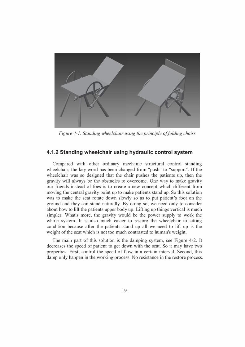
Figure 4-1. Standing wheelchair using the principle of folding chairs
4.1.2 Standing wheelchair using hydraulic control system
Compared with other ordinary mechanic structural control standing wheelchair, the key word has been changed from “push” to “support”. If the wheelchair was so designed that the chair pushes the patients up, then the gravity will always be the obstacles to overcome. One way to make gravity our friends instead of foes is to create a new concept which different from moving the central gravity point up to make patients stand up. So this solution was to make the seat rotate down slowly so as to put patient’s foot on the ground and they can stand naturally. By doing so, we need only to consider about how to lift the patients upper body up. Lifting up things vertical is much simpler. What's more, the gravity would be the power supply to work the whole system. It is also much easier to restore the wheelchair to sitting condition because after the patients stand up all we need to lift up is the weight of the seat which is not too much contrasted to human's weight.
The main part of this solution is the damping system, see Figure 4-2. It decreases the speed of patient to get down with the seat. So it may have two properties. First, control the speed of flow in a certain interval. Second, this damp only happen in the working process. No resistance in the restore process.

20
Figure 4-2. Standing wheelchair using hydraulic control system
4.1.3 Standing wheelchair using parallelogram
During the research about the related work of standing wheelchair, it is found that lots of wheelchair published online paid much attention on the motion of the back. In the sitting position, it is 90° between the seat and back or maybe a little bit larger than that to make patient sit more comfortable. But in the process of standing, the back cannot be always perpendicular to the seat. It need to, at least at final standing position, be vertical and then the patients can stand up. To solve this problem, variety of solution has been designed, like a series of connecting rods and electrical control the back. There is a simpler structure to solve this by using the parallelogram.
The main seating portion is a parallelogram with hinges at each vertex. So this structure is deformable. Compression springs are installed at two non-adjacent vertices. Those springs will provide the power to reform the parallelogram. The front vertical side of the parallelogram is fixed on the skeleton. According to the property of parallelogram, the opposite side will be lifted due to spring force see figure 4-3. With the horizontal rod sloped positively, the seat and the movement during reformation fit the way that human stand up.
When the patient wants to stand up, push the armrest at both sides. Button will be turned on. At the beginning, the centre of gravity is at the back of seat. Chair back will rotate forward by human force. The centre of gravity will also

21
move forward. The weight cannot suppress the seat any more. And the main seating portion reforms to fit the standing process.
Figure 4-3. Standing wheelchair using parallelogram
4.2 Comparison and results
4.2.1 Comparison
4.2.1.1 Folding chair principle The structure of this wheel chair required higher precision. Because, the
seat is cooperative to the back and they will rotate correspondingly. The rod extended from the handrail must be determined carefully to prevent conflict. The sleeve out of the shaft is slide on it, higher surface property is essential. Otherwise, too big friction will consume considerable power.
The power supply is designed as using the arm strength from the patient. This force need to lift the entire body weight and work the seat-back rotation.

22
Work against the friction from the sleeve and shaft, the joint of the seat and back. A certain amount of force is demanded. But we need to put the fact in to consideration that the disable people are more used to push the wheel and the strength is stronger than normal people.
Due to the special design, it is more suitable for the light disabled patient whose upper body is intact. Those who are a highly disabled cannot operate this wheelchair, while highly disabled people cannot even stand up though. And the extended rod from the handrail need a large space under the seat, which means this type of wheelchair can only be design separately.
To produce this type of wheelchair, the cost will not be much. It is drove totally by the mechanic structure using human strength. So it will not have power cost. And all the cost of the wheelchair is material and assembles.
The force is provided by the patient itself, so they can control the speed of the rotation of the seat. It is easier for them to keep balance. But, with the same reason, put a damping system will be unwise, because it will cause large power consumed by the damp.
4.2.1.2 Hydraulic controlling wheelchair The frame of the chair part is a simple task. A normal wheelchair uses a
rotatable seat. The hydraulic part is the main design. The result of the survey shows that the hydraulic valve can be made very small, approximately within ten centimetres. In this system a tank will be inevitable. The bulk and weight can be a problem for the structure. In general, the structure is not so complex, because the complex part can be sorted in a hydraulic box contained all the valves, tank and oil pump if needed.
The power consumption is the essence of this type of wheel chair. As it was mentioned above, the power supply will be the patient's weight itself. And after the patient stand up, the seat will be easy to lift restore the sitting condition from standing position. Neither motor nor human strength is needed. It will be the best power save type of wheel chair.
This type of wheelchair can be applied to any patient theoretically, if the patient can stand, he or she can use this wheelchair. But it has only one exception. For those who is tall in their height, the chair need to adjust the seat according to the movement of the central gravity point.
With a normal cost of the normal chair, the hydraulic system will be an extra cost. In the survey, a good valve produced by a good company can cost a lot. A better valve can make the flow of oil more smooth and within smaller

23
leak and higher precision. In our wheelchair application, the system is not so delicate. So we can choose cheaper parts to strike the balance or depending on the patient's economic situation.
This wheel chair has not very complex frame. So it will not have big danger of mechanical problem or other risk of fall down. All the motion, actually the only motion, is the rotation of the seat. A safety switch will be installed on it, only with the trigger opened then the wheelchair can be activated. What's more, with a better valve the performance of the wheel chair will be more stable.
4.2.1.3 Wheel chair with parallelogram The main part of this wheelchair is exactly the same as all other normal
wheelchair. The only difference is a parallelogram structure instead of the normal seat. The parallelogram seat can be made very thin as well. So the overview of this wheelchair will not be different form the ordinary one. As a matter of fact, the parallelogram seat part can be produced separately and installed on a normal wheelchair.
Using this type of standing wheelchair, we need to lift up not only the human body but the parallelogram seat. This part will move with you so as to support you stand up. The force required is litter bit larger than the first type of wheelchair using folding chair principle. According to the geometric property of the parallelogram, we can put several springs between those non-adjoined vertices of the parallelogram. Those springs can provide the compression power between tow vertices. With the distance decrease, the parallelogram will transform from a square to a sharp quadrilateral. The force of springs can be set arbitrary large. Theoretically, so large that no more other power is needed to support the weight of both the human body and the parallelogram.
The main part of the parallelogram can be produced separately. So that this wheelchair can be installed to any chair or wheelchair which is standard dimensions. It can not be installed on any type of chair because the different size and fancy style nowadays. Since the standing process is natural and not required strong arm strength. Any patient can use this type of wheelchair without exception.
The produce cost of this wheelchair is close to the normal wheelchair if the motor is not considered. The main frame of the chair body is purely mechanic. And slide friction is not much so the surface property is not demand. Even the motor is set on the system, due to the springs on the parallelogram, a small

24
motor provided the slight torque can drive the whole system. So the produce will be higher but still in reasonable range.
If the motor is not used than the power supply will be laid on the spring. The spring can not control the speed of the motion. So if any mechanic problem occurred, the patient maybe lifted in a fast speed. It will make the patient fell down. This is the problem need to avoid by using springs. A switch and the personalized springs design can solve this problem.
4.2.2 Results
Table 4-1. Assessment
complexity
Power consumption
applicability
economy
safety total
1folding wheelchair
8 6 8 9 6 37
2hydraulic controlling
7 8 6 6 8 35
3parallelogram
8 9 9 8 7 41
In general consideration, the third solution, standing wheelchair with parallelogram is the best solution.
4.3 Design of the best solution
There is a brief idea at first as follow. The main seating portion is a parallelogram hinged at each vertex. So this
structure is transformable. Extension springs are installed at two non-adjacent vertices. Those springs can provide the power to transform the parallelogram. The front vertical side of the parallelogram is fixed on the base. According to the geometry property of parallelogram, the opposite side will be lifted. With the horizontal rod sloped, the seat and the movement during transformation fit the way that human stand up.

25
The armrest has two functions; the first is to make people stand easier and safer. Support from the armrest can compensate the weakness in legs. Secondly, push the armrest to create the power to rotate the back.
When stand up, push the armrest at both sides. At the beginning, the centre of gravity is at the back of seat. Chair back will rotate forward by human force. The centre of gravity will also move forward. The weight cannot suppress the seat any more. And the main seating portion transforms to fit the standing process. See it in Figure 4-4.
Figure 4-4. Main view of final modelling
4.3.1 The flowchart of wheelchair
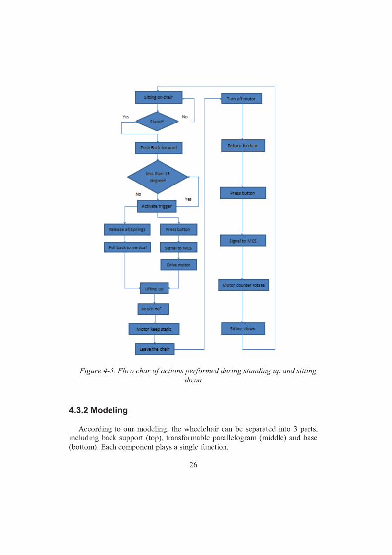
Next, a flowchart about how our wheelchair works was made, see Figure 4-5.
26
Figure 4-5. Flow char of actions performed during standing up and sitting
down
4.3.2 Modeling
According to our modeling, the wheelchair can be separated into 3 parts, including back support (top), transformable parallelogram (middle) and base (bottom). Each component plays a single function.

27
4.3.2.1 Back support (top) This is the model of top part, see Figure 4-6.
Figure 4-6. Assembly drawing of top part in wheelchair
The back support is a rotatable board located on the back of the chair. Research shows that when people want to stand up, the first action will be to bend his or her back forward. This behaviour is to move the centre of gravity ahead so that our legs can support our whole body up, otherwise the force from legs can only generate the moment make us fall over backwards. And it becomes the natural action to stand up. Handicapped people do not have strong enough leg strength. They use other support. A more natural way is designed to make standing more comfortable. So this board designed will follow the upper body go forward or backward. It is embed in the chair back. In order to fix the body on the backboard, a belt will be tied across the chest. See Figure 4-7.

28
Figure 4-7. Schematic diagram of how does the back support work
To bring a most comfortable standing experience for the consumers, a research was conducted to find out the accurate angle to stand up naturally. A video of a normal person standing up was recorded, and selected the most representative moment to determine the angle. See Figure 4-8.
Figure 4-8. Determine the angle when person start to stand up
29
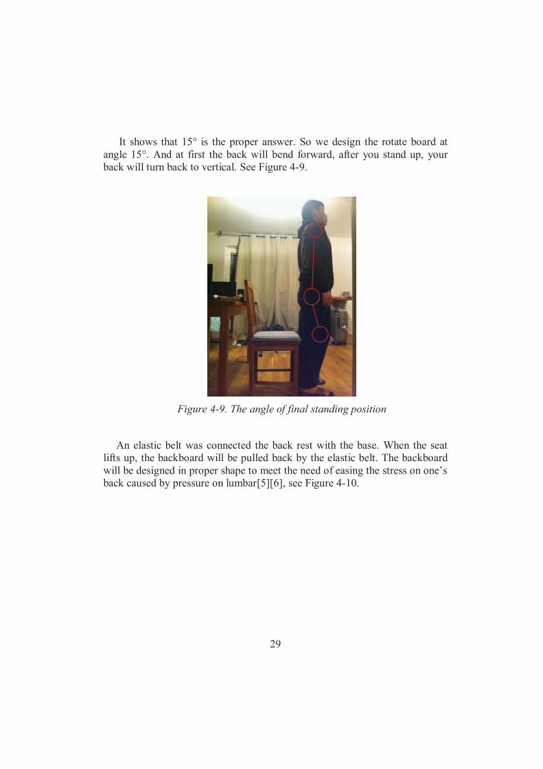
It shows that 15° is the proper answer. So we design the rotate board at
angle 15°. And at first the back will bend forward, after you stand up, your back will turn back to vertical. See Figure 4-9.
Figure 4-9. The angle of final standing position
An elastic belt was connected the back rest with the base. When the seat lifts up, the backboard will be pulled back by the elastic belt. The backboard will be designed in proper shape to meet the need of easing the stress on one’s back caused by pressure on lumbar[5][6], see Figure 4-10.

30
Figure 4-10. Schematic diagram of how does elastic belt work
4.3.2.2 Transformable parallelogram (middle) This is the model of the middle part, see Figure 4-11.
Figure 4-11. Assembly drawing of middle part in wheelchair
By using this mechanism, the back of the chair is always vertical. A
rotatable backboard keep the back always move with the body. See Figure 4-12.
31
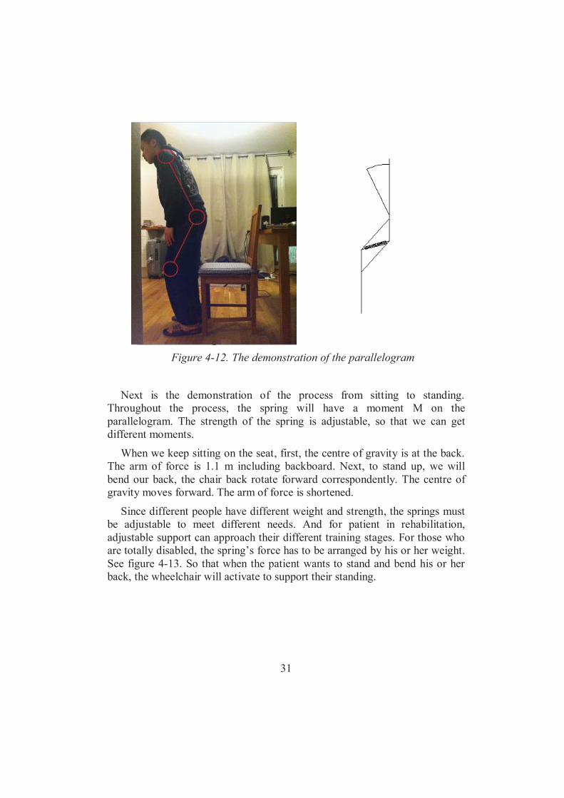
Figure 4-12. The demonstration of the parallelogram
Next is the demonstration of the process from sitting to standing. Throughout the process, the spring will have a moment M on the parallelogram. The strength of the spring is adjustable, so that we can get different moments.
When we keep sitting on the seat, first, the centre of gravity is at the back. The arm of force is 1.1 m including backboard. Next, to stand up, we will bend our back, the chair back rotate forward correspondently. The centre of gravity moves forward. The arm of force is shortened.
Since different people have different weight and strength, the springs must be adjustable to meet different needs. And for patient in rehabilitation, adjustable support can approach their different training stages. For those who are totally disabled, the spring’s force has to be arranged by his or her weight. See figure 4-13. So that when the patient wants to stand and bend his or her back, the wheelchair will activate to support their standing.

32
Figure 4-13. The change of the centre of gravity when person want to
stand up
4.3.2.3 Base (bottom) This is the modeling of bottom part, see Figure 4-14.
Figure 4-14. Assembly drawing of bottom part in wheelchair

33
The bottom is designed in view of the traditional wheelchair. Size of back
wheels is larger than front wheels, which aims to keep more weight at the back for keeping balance, when forming a standing up process. A skeleton will be added to the base in view of original edition of wheelchair for a larger space and more developing potential in the upcoming designs.
4.3.2.4 Displacement restrict trigger
Figure 4-15. Displacement restrict trigger
The final angle between rod and horizontal plane is 60 . According to our calculation, lifting force provided by spring and motor equal to weight. So that 60 is the ultimate degree. We control the angle by measuring the gear rod coordinate to side gear. The length of gear rod is 0.684m. At the edge of rod we made a bun at the edge. After 2 second, a signal of stuck on this position will be delivered to the controlling system.
4.3.2.5 Spring lock To prevent from the accidentally start of the standing process. A trigger on
the system is necessary. It can be activated only with the trigger is on. The simplest solution of the trigger design is to add a handle aside the seat. The handle connects to some block bars to stop the motion. The principle of our thesis purpose is to design a standing wheelchair in a more natural way. Apparently, pushing a handle while standing up is not natural. To carry out

34
our principle, the trigger installed on our wheelchair need no extra action by the patient. The patient use our wheelchair need only to bend their back and then they can be support to stand. So the method to solve this problem is to activate the trigger by the motion of the back.
Figure 4-16. Main view of our spring lock
Figure 4-17. Spring lock locks the whole standing system

35
The trigger system has three parts. See figure 4-16. There is a slot on the rod beneath the back. A piston fixes on a vertical side of the parallelogram between the back and rob with the slot. Upper end of the piston is connected with back. The back’s rotation can drive the piston move up. At the lower end of the piston is a block bar which can be inserted into the slot. With the block bar inserted in the slot, the rod can not rotate so that the system is locked, see figure 4-17. With this trigger on the wheelchair, there is no accidentally activation. As long as the patient sit on the wheelchair and lean on the back. The wheelchair can not move even some mechanic problem or electronic problem accrued.
In standing proceeding, patient first bend their back and the back of chair rotate too. The rotation of chair back lift the piton and the bar pull out of the slot. The system activated. Then the parallelogram support the patient stands up. In sitting proceeding, the most natural way is sit down first and then straight their back, so no confliction during the sit proceeding. This solution can well meat the purpose.
4.3.2.6 Motor transmission design
4.3.2.6.1 Chain transmission (Abandoned) In order to avoid motor displacement, we designed a chain transmission.
See figure 4-18.
Figure 4-18. Chain transmission

36
It is consisted of three transmission shaft, one gear shaft and one chain. The motor provide force of rotation to drive the chain. The Gear shaft will rotate correspondently by transmission from chain. The gear shaft not only rotates itself, but also moves along the chain. This kind of motor drive is reasonable when teeth are precisely calculated, because the transmission status is instable. It is hard to make sure that every tooth is engaged to each other. But it does have advantage of fixing motor on a stable position.
4.3.2.6.2 Moving motor (Chosen)
Figure 4-19. Moving motor
We figure out another drive method. Install the motor on a “gear car”, so it
will work accompany with movement with gear car, see figure 4-19. This method need less drive member, so it will make the lifting system more stable, and it is easy to calculate the relationship between the speed of motor and the speed of standing up. So we finally choose the second method, and we apply this structure to our wheelchair.

37
5 Chapter: Calculation
We check on the Internet that average male weight is 81.9kg and average female weight is 66.7kg [7]. So in our calculation, we assume that people’s weight is 90kg, so our wheelchair can meet most people’s needs.
5.1 Deformation of the base
First of all, we calculate the deformation of the base. We need to ensure that the base can support people’s weight, and the deformation of the base is acceptable.
Our base structure is truss structure, and we do stress analysis of this structure, see Figure 5-1. The material of our base is aluminum 6061, so we check on the Inventor that Young’s modulus 968.9 10E Pa [8].
Figure 5-1. Parallelogram structure
In this case, four nodes (written in red color), four elements (number
encircled) and 8 degrees of freedom Qi, were identified according to figure 5-2.

38
Figure 5-2. Nodes, elements and degrees of freedom
The connectivity among elements can be described according to the following table:
Table 5-1. Connectivity among elements
Element number Global nodes Degree of freedom 1 12 Q1Q2Q3Q4 2 23 Q3Q4Q5Q6 3 34 Q5Q6Q7Q8 4 41 Q7Q8Q1Q2
The local stiffness matrix is given by:
Element 1:

39
0.65el 2 1 0.65 10.65e
x xll
2 1 0e
y yml
Element 2:
0.2el 2 1 0e
x xll
2 1 1e
y yml
Element 3:
0.65el 2 1 1e
x xll
2 1 0e
y yml
Element 4:
0.2el 2 1 0e
x xll
1m
By obtaining the coordinates of each node, we can get the corresponding values of l, and m, for each element. In table 5-2, such values are presented.
Table 5-2. Coordinates and values of l and m for each element
Elements Global nodes
(x1,y1) (x2,y2) l m
1 12 (0,0) (0.65, 0) 1 0 2 23 (0.65,0) (0.65,0.2) 0 1 3 34 (0.65,0.2) (0,0.2) -1 0 4 41 (0,0.2) (0,0) 0 -1
Now, we can write the k matrix for each element as follows:

40
9 4
1
1 2 3 41 0 1 0 10 0 0 0 268.9 10 4.5 101 0 1 0 30.62
0 0 0 0 4
k0 01 0
9 4
2
3 4 5 60 0 0 0 30 1 0 1 468.9 10 7.5 100 0 0 0 50.20 1 0 1 6
k0 10 0
9 4
3
5 6 7 81 0 1 0 50 0 0 0 668.8 10 4.5 101 0 1 0 70.62
0 0 0 0 8
k
9 4
4
7 8 1 20 0 0 0 70 1 0 1 868.9 10 7.5 100 0 0 0 10.20 1 0 1 2
k0 10 0
Notice how the degrees of freedom for each element have intentionally been associated to rows and columns in the respective matrices. Such relationship will determine the global K matrix as follows:
7 7
8 8
7 7
8 8
7 7
8 8
7 7
8 8
1 2 3 4 5 6 7 81 5 10 0 5 10 0 0 0 0 02 0 2.58 10 0 0 0 0 0 2.58 103 5 10 0 5 10 0 0 0 0 04 0 0 0 2.58 10 0 2.58 10 0 05 0 0 0 0 5 10 0 5 10 06 0 0 0 2.58 10 0 2.58 10 0 07 0 0 0 0 5 10 0 5 10 08 0 2.58 10 0 0 0 0 0 2.58 10

41
Now, by noticing that Q1, Q2, Q3, Q4, Q7 and Q8 are zero because of the boundary conditions, the global system of equations is reduced to a system of 2 eqs. with 2 unknown displacements. Then, the matrix is reduced as follows:
5 67
58
6
5 10 00 2.58 10
Q QQQ
Correspondingly, the vector for the external forces becomes:
5
6
0
2
FF GF
NGNG
4502
900
And the system of equations to solve is given by
K Q F
Where, finally, Q is estimated as:
mmQQ
Q0195.00
6
5

42
5.2 Spring design
We decide to use 5 springs, final position is 60 between seat and horizontal plane.
First, we assume that the upward force provided by motor is 600N. According to the definition of holding torque, the maximum torque of the motor (whatever resistant or provided) cannot be larger than holding torque. If we divide it by the arm, the answer will be the maximum force of the motor. So when the angle is 0 between seat and horizontal plane, the maximum upward force of total springs is 600N (if the force is larger than this, the motor cannot resist this force).
When the angle is 60 , stress analysis is shown as followed, see Figure 5-3.
Figure 5-3. Stress analysis (First time design, 60 )
300 sin30 =150N
2 2 210.65 0.2cos30
2 0.65 0.2x
1 0.49x m
0.49 0.2sin 30 sin y
12y

43
1sin12 150sF N
1721sF N
1
1144.2
5s
es
FF N
When the angle is 0 , stress analysis is shown as followed, see Figure 5-4.
Figure 5-4. Stress analysis (First time design, 0°)
2
0.686000.2
=2040N
sF
2
2408
5s
es
FF N
2 22 0.65 0.2 0.68x m
Then we can calculate k,
2 1
2 1
1388 1.388es esF F N Nk m mmx x
11 0.386esF
x xk
Original length
After that we can design our spring, 4
38a
c m
G dkN D

44
Where Ga Rigidity modulus of wire
d Diameter of Wire
Nc The effective turns number
Dm Middle diameter We did some research on the Internet. The most commonly used rigidity
modulus of wire is 79000 N/m
79000 N/maG
According to the size of our wheelchair, we choose the diameter of wire as 5 mm, and the turns number as 40, so the effective turns number as 38.
mmd 5 4038c
NN
Then we determine the middle diameter,
3
4
388579000388.1mD
48mD mm
Then we optimized the spring. according to holding torque, the upward force provided by motor cannot less than 450N, because if the upward force provided by motor less than 450N, the upward force provided by spring will larger than 450N, the motor will not resist the force provided by spring. After we discuss, we decided to let motor provide 500N upward force. Similarly, the angle is 0 between seat and horizontal plane, the maximum upward force of total springs is 500N.
When the angle is 60 , stress analysis is shown as followed, see Figure 5-5.

45
Figure 5-5. Stress analysis (Second time design, 60°)
400 sin30 200N
1sin12 200sF N
1962sF N
1
1192.4
5s
es
FF N
When the angle is 0 , stress analysis is shown as followed, see Figure 5-6.
Figure 5-6. Stress analysis (Second time design, 0°)
2
0.685000.2
=1700N
sF

46
2
2340
5s
es
FF N
Then we can calculate k,
2 1
2 1
340 192.4 7770.68 0.49
=0.777
es esF F Nk mx xN
mm
11 0.24esF
x x mk
Original length
After that we can design our spring, 4
38a
c m
G dkN D
3
4
388579000777.0mD
59mD mm
This is the spring which our design to make motor provide minimum force. You can see the spring parameters in followed table.
Table 5-3. Final selection of the spring parameters
Parameter Unit Value
d mm 5
Nc 38
Dm mm 59
5.3 Stability calculation
As we know, when we use wheelchair, sometimes we need to lift the front wheel, so there is an angle between seat and horizontal plane. If the angle is

47
too big, the wheelchair will tip over, so we need to calculate which angle is maximum.
First of all, we checked on the Internet, we find average height of male in Sweden is 181.5cm, average height of female is 166.8cm [9]. We use male as a template. And we know that, the proportion of upper body and lower body is almost 5:8. Then we measure the length of our seat, it is 0.645m, the distance between back wheel and seat is 0.6m. So we can calculate that the upper body’s length is 0.7m, the length of thigh link is 0.645m, the length of shank link and foot link is 0.47m, see Figure5-7.
Figure 5-7. Body size distribution in our wheelchair
Then we should analyze body’s weight distribution.
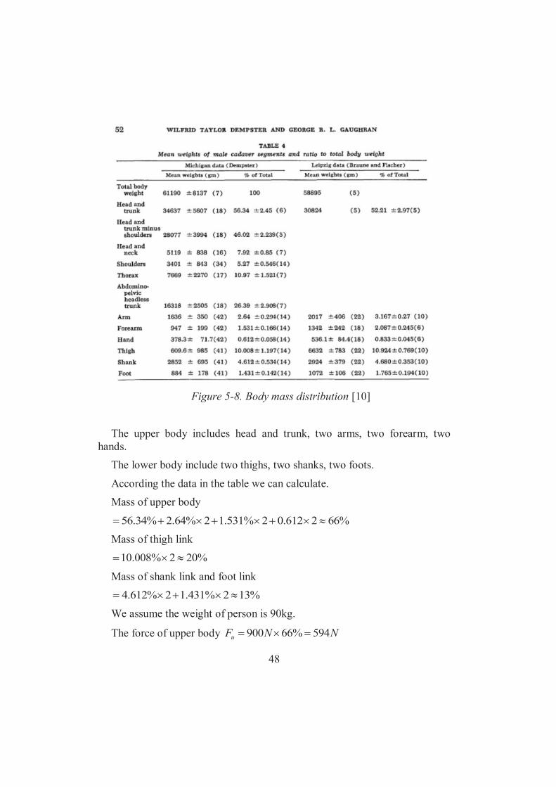
48
Figure 5-8. Body mass distribution [10]
The upper body includes head and trunk, two arms, two forearm, two
hands. The lower body include two thighs, two shanks, two foots.
According the data in the table we can calculate.
Mass of upper body
%662612.02%531.12%64.2%34.56
Mass of thigh link %202%008.10
Mass of shank link and foot link
%132%431.12%612.4
We assume the weight of person is 90kg.
The force of upper body NNFu 594%66900

49
The force of thigh link NNFt 180%20900
The force of shank link and foot link NNFsf 116%13900
After that, we do stress analysis, see Figure5-9, then we can calculate the maximum angle.
Figure 5-9. Stress analysis in stability calculation
uM : The moment of upper body.
tM : The moment of thigh link.
sfM : The moment of shank link and foot link.
sin6.035.0594uM
)sin6.0cos3225.0(180tM
)sin6.0sin235.0cos645.0(116sfM
When sftu MMM , the value of is maximum.
cos87.132sin64.714
5.10
Therefore, the maximum angle between seat and horizontal plane (rotation angle) is 10.5 .

50
Then, according to our design, we design two anti-dumping wheels in our wheelchair, see figure 5-10. Because of these two wheelchair, we can guarantee that if the rotation angle is bigger than 10.5 , there is two wheels support our wheelchair, so that the wheelchair will not dump.
Figure 5-10. Anti-dumping wheels
5.4 Motor selection
According to the spring design, the motor need provide 500N upward force, then we design transmission system in order to make the motor need less torque, see figure 5-11.
Figure 5-11. Schematic of transmission
51
111 TP
222 TP
During the transmission process, the power is constant, so
21 PP
2211 TT
22
11 r
vTrvT
22
11
11mz
Tmz
T
2
1
2
1
zz
TT
So if we change z1 and z2, we can make torque of motor less. Then we choose modulus of gear is 2mm, the tooth of gear 2 is 30.
mmmmzd 06.06030222
mNdFT 1503.05002
22
Then we choose the tooth of gear 1 is 10, so
mNT 51
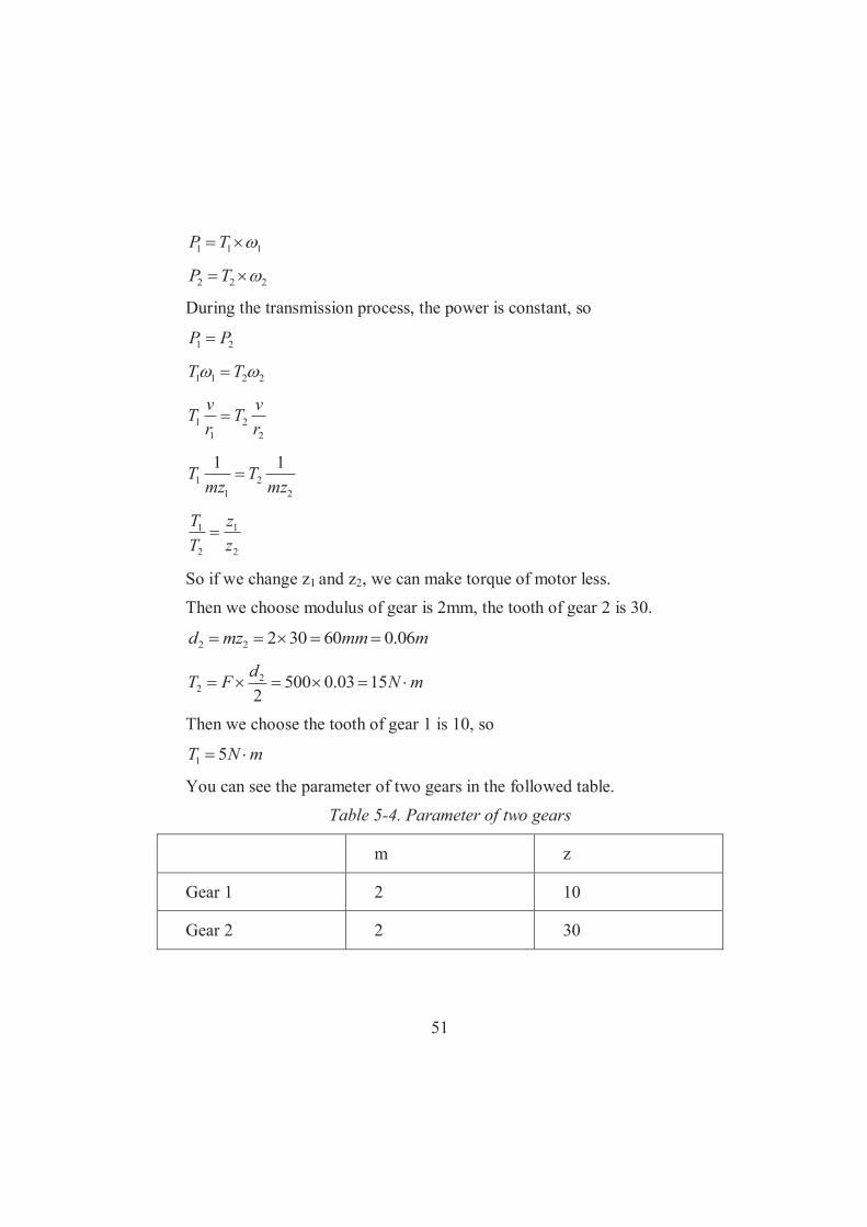
You can see the parameter of two gears in the followed table. Table 5-4. Parameter of two gears
m z
Gear 1 2 10
Gear 2 2 30

52
T1 is the maximum torque of motor, so the holding torque of motor can not less than this. Then according to the followed picture 5-12, we choose a motor.
Figure 5-12. Parameter of motor [11]
According to this picture, our choice is 85BYGH4802. Furthermore, when the motor is not energized, the motor can not rotate, so we also need install a electromagnetic holding brake [12] on the motor to achieve this goal.
5.5 Stress analysis by using FEM
We made Dynamic and stress analysis on our product to search for the result of Mises, displacement and safety factor. Stress analysis is tested in Inventor 2014 environment function.
According to the stability test, we click out seating part out of assembly. Scale of body weight distribution is approximately 2:1. So we put 2/3 90 10N concentrated force on the end of seat. And face pressure of 828.72Pa (30 10/0.362). We assign that our material is Aluminium 6061 [13]. And the thickness of seat is 10mm at first. We fix both side of the seat. We assume the element type as default. Result of 10mm thickness is presented as follow.

53
Figure 5-13. The maximum result of Mises when the thickness of seat is
10mm The maximum result of Mises is 15.47MPa on each edge corner of seat.
Figure 5-14. The maximum result of displacement when the thickness of
seat is 10mm The maximum result of displacement is 0.3956mm on the middle point of
the edge.

54
Figure 5-15. The result of safety factor when the thickness of seat is 10mm According to the result of safety factor, it is far lower than the maximum.
Next, we change the data of seat thickness to 15mm and made a second
test.
Figure 5-16. The maximum result of Mises when the thickness of seat is
15mm
The maximum result of Mises is 5.848MPa on each edge corner of seat. With the data altered a half more, the value of Mises decreased by nearly a half.

55
Figure 5-17. The maximum result of displacement when the thickness of
seat is 15mm
The maximum result of displacement is 0.1157mm on the middle point of the edge. The value is only one third of the original.
Figure 5-18. The result of safety factor when the thickness of seat is 15mm With the thickness increased, the seat is undoubted safer than before.
According to the result, we are sure that when you sit on the wheelchair, Aluminium 6061 is a qualified material to our design. Our purpose is not only

56
to test whether the seat will be cracked, but also to measure the displacement of the supporting of main deformable part.
We not only calculated Truss analysis by hand, but also made a FEM test on Inventor2014 in assembly stress analysis. We do assembly of right side of parallelogram to accomplish the similar condition of truss. We fix every vertex except upper right one. And put a concentrate force of 450N on top of upper right vertex. There must be some deviation due to the difference of cross section between ideal state and real one. Result is presented as follow.
Figure 5-19. The maximum Mises of parallelogram
The maximum result of Mises is 7.87Mpa on the down right vertex.

57
Figure 5-20. The maximum displacement of parallelogram
The maximum result of displacement is 0.049mm on upper right.
58
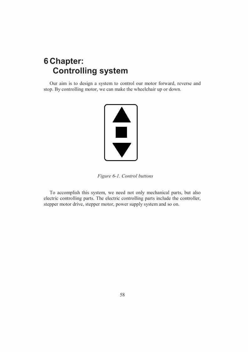
6 Chapter: Controlling system
Our aim is to design a system to control our motor forward, reverse and stop. By controlling motor, we can make the wheelchair up or down.
Figure 6-1. Control buttons
To accomplish this system, we need not only mechanical parts, but also electric controlling parts. The electric controlling parts include the controller, stepper motor drive, stepper motor, power supply system and so on.

59
Figure 6-2. The schematic of system [14]
In our opinion, first we insert program into controller. When we press the controlling button, the program in controller will give signal to stepper motor driver, then the stepper motor driver receive the signal, stepper motor driver will control the working of motor according to our need, and the power supply provide the power of motor to make sure that the motor has enough energy to work. Through these equipments, we can easily control the state of motor.

60
6.1 Controller selection
Figure 6-3. MCS-51 core [15]
Our controller choice is Intel MCS-51. The Intel MCS-51 is Harvard architecture, single chip micro-controller series which was developed by Intel in 1980 for use in embedded systems with multitasking real-time operating system support. This single chip have many advantages, such as cheap, simple circuit, small size and low power consumption, it is extremely used in the industry now. For example, to control a motor does not need to use a PC, just use single chip and drive circuit can achieve the same goal.
6.2 Stepper motor driver selection
Figure 6-4. DQ860MA driver [16]

61
Figure 6-5. The parameters of driver [16]
Stepper motor driver our choice is DQ860MA which is brushless DC motor drivers that can be used for both positioning and velocity control applications. When it receives a pulse signal, it will drive the stepper motor to rotate a fixed angle. It rotate step by step, each step is a fixed angle. By controlling the number of pulses controls angular displacement, also by controlling the frequency of pulses controls motor’s speed and acceleration.
6.3 Power supply selection
Figure 6-6. JSS-120-24 Switch Power Supply [17]

62
Figure 6-7. The parameters of JSS-120-24 Switch Power Supply [17]
We choose a power supply named JSS-120-24 Switch Power Supply, it is
high efficiency, high reliability, low cost. It has over current, over voltage, short circuit and overheats protections. It use PWM control and regulation, ensure the steady and precise output voltage. The output voltage is 24V and the rated current is 5A.

63
Table 6-1. The price list of controlling system
Controlling System Unit Price [SEK]
Amount Total Price [SEK]
MCS-51 core 5 1 5
DQ860MA driver 320 1 320
JSS-120-24 230 1 320

64
7 Chapter: Conclusion and future work
7.1 Conclusion
After stress analysis and calculation, we have validated our ideas. We use the parallelogram to achieve the goal that our wheelchair can make people stand up. We put springs in the parallelogram that can lift different weight of person. The spring which we designed is removable. So we can meet different disabled people’s requirements. We have better applicability than other wheelchairs. And we put motor in our wheelchair, our wheelchair will work steadily by using motor. And we can use motor to control the lifting speed. In addition, we use belt driving to design our back of wheelchair. That can make the back deformable during standing to pursue natural posture.
We use FEM to sort out stress analysis, and use our mechanical knowledge that we learned to calculate safety and stability of the structure. Then we design our spring in parallelogram. We can guarantee our wheelchair have enough power to help disabled people to stand up. On the other hand, we analysis the important component to make sure our wheelchair will not be shattered during sitting and standing. With the calculation of stability, we design two anti-dumping wheels in our wheelchair to balance the chair.
Furthermore, we design a structure to activate our spring. It can make sure that if there is no person sit on the wheelchair, the wheelchair will not lift up. And when people sit on the wheelchair, they want to stand up, they can use this device to activate spring. And we also design a limit switch. It will ensure that when the wheelchair lift 60 , it will not lift any more.
This design solves the issues we have stated. We believe that through this work we can achieve our proposal. Our design may not be perfect, but worth taking into account.
7.2 Future work
Time is limit for our project, so we still have shortcomings in our design. First, we check the safety and deformation of some important part, we only
make sure these parts are safe, but we do not optimize them. In the future, we

65
can optimize them to let size smaller. If we can find the smallest size of each part, the wheelchair will become cheaper.
Second, because of our major, we do not have much knowledge about electrical controlling. We hope if somebody is interested in our project, he or she can help us to design the electrical controlling. Then the motor in our wheelchair can be controlled as what we need.
Third, in our design, the whole motor need to move forward during the wheelchair stand up, but this motor which we choose is 3.5kg, we consider it is heavy, it is inconvenient to move. Although we design a chain mechanism, it can fix the motor (do not need to move motor) when the wheelchair stand up, because of its instability and uncertainty during work, so at last we abandon this idea. In the future, we hope somebody can design some structures to make the motor without moving when the wheelchair standing.
Last but not the least, we would like to figure out a adapter to coordinate with standard wheelchair like a plug. If we have this adapter, we can apply the parallelogram structure in more wheelchairs. If somebody wants to buy standing wheelchair, he or she do not need to buy a whole wheelchair, only buy parallelogram structure, then install it to his or her own wheelchair. That wheelchair can achieve the same goal to stand up. So it will make the standing wheelchair cheaper.
66
Reference
[1] “Inventor-products Overview,” <http://knowledge.autodesk.com/support/inventor-products>[accessed May 21 2014].
[2] T. A. Kuiken, “Manually operable standing wheelchair,” WO2004096620 A111-Nov-2004. <http://www.freepatentsonline.com/7165778.pdf>[accessed 28 April 2014].
[3] “Prosthetic apparatus for supporting a user in sitting or standing positions,” <https://docs.google.com/viewer?url=patentimages.storage.googleapis.com/pdfs/US6125957.pdf>[accessed 28 April 2014].
[4] “Dual-Purpose Wheelchair Mechanism Designs.pdf” <http://www.iaeng.org/publication/IMECS2009/IMECS2009_pp1704-1708.pdf>[accessed 28 April 2014].
[5] J. Arva, G. Paleg, M. Lange, J. Lieberman, M. Schmeler, B. Dicianno, M. Babinec, and L. Rosen, “RESNA Position on the Application of Wheelchair Standing Devices,” Assist. Technol., vol. 21, no. 3, pp. 161–168, 2009.
[6] S. Goemaere, M. V. Laere, P. D. Neve, and J. M. Kaufman, “Bone mineral status in paraplegic patients who do or do not perform standing,” Osteoporos. Int., vol. 4, no. 3, pp. 138–143, May 1994.
[7] “Body weight,” Wikipedia, the free encyclopedia. 28-Apr-2014.
[8] “6061 aluminium alloy,” Wikipedia, the free encyclopedia. 28-Apr-2014.
[9] “Human height,” Wikipedia, the free encyclopedia. 21-May-2014.
[10] W. T. Dempster and G. R. L. Gaughran, “Properties of body segments based on size and weight,” Am. J. Anat., vol. 120, no. 1, pp. 33 54, Jan. 1967.
[11] “Hybrid Stepping Motor 85BYGH,” <http://detail.1688.com/offer/24577941.html>[accessed 22 May 2014].
[12]“Electromagnetic brake,” Wikipedia, the free encyclopedia. 04-May-2014. [13] “6061 aluminium alloy,” Wikipedia, the free encyclopedia. 28-Apr-2014.

67
[14] “Based on Single Chip Stepping Motor Motion Control System Design. PDF - Academic Research - Education Resource Download,” <http://www.educationsresources.com/2096338/>[accessed 21 May 2014].
[15] “Intel MCS-51,” Wikipedia, the free encyclopedia. 21-May-2014. [16] “Stepper Motor Driver DQ860MA:Stepper Motor Driver DQ860MA
Wholesaler,” <http://www.wantmotor.com/ProductsView.asp?id=271&pid=82>[accessed 21 May 2014].
[17]“Stepper Motor Power Supply,24v 5a Switch Mode Power Supply,Dc Power Supply - Buy Stepper Motor Power Supply,24v 5a Switch Mode Power Supply,Dc Power Supply Product on Alibaba.com” <http://www.alibaba.com/product-detail/stepper-motor-power-supply-24v-5a_1558202145.html?s=p>[accessed 21 May 2014].

68
Appendix: The drawings of main components
A.1 Basic L

69
A.2 D Adapter
70
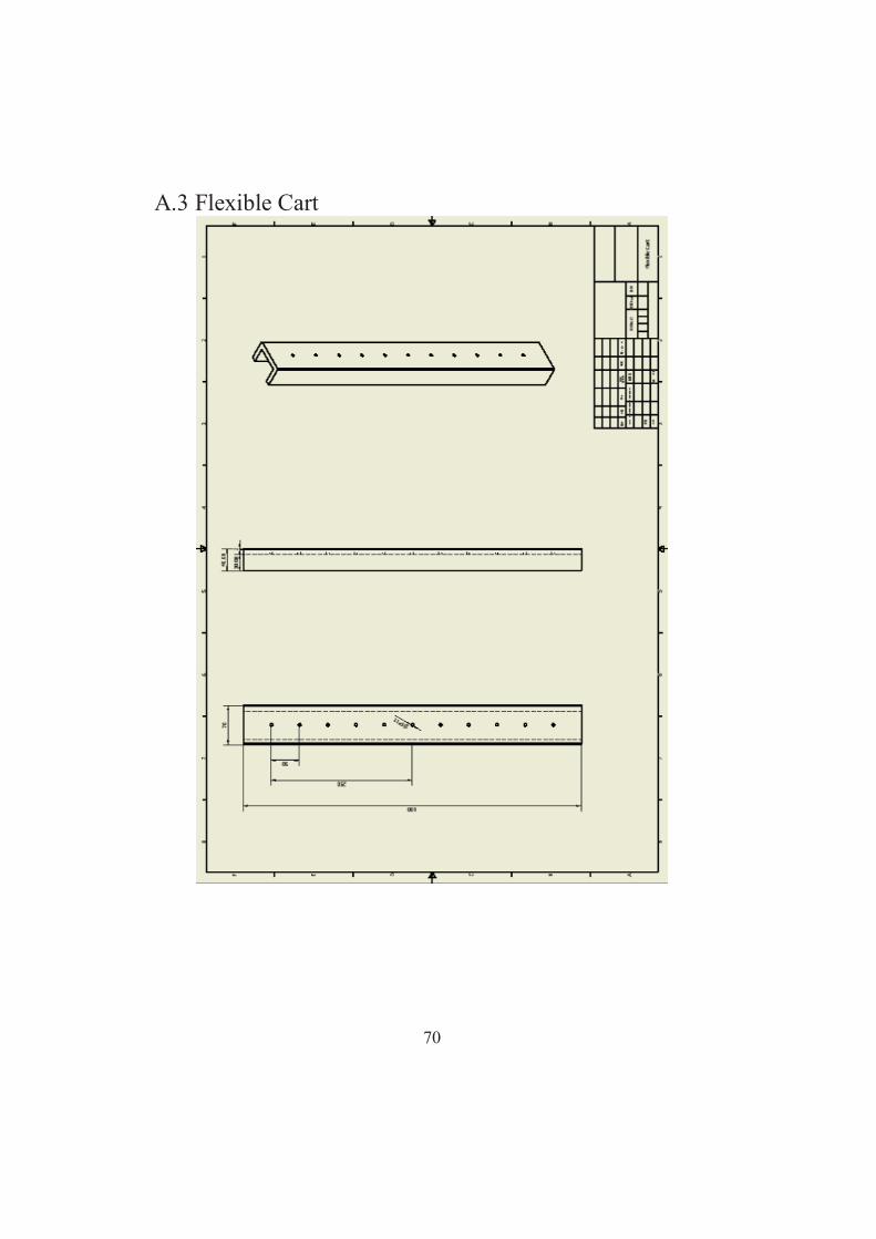
A.3 Flexible Cart

71
A.4 Parallelorgram Stick

72
A.5 Piston Cart

73
A.6 Under Belt Fixer