New manual - Lowes Holidaypdf.lowes.com/installationguides/850664002052_install.pdfJet Pump...
24
15
Transcript of New manual - Lowes Holidaypdf.lowes.com/installationguides/850664002052_install.pdfJet Pump...

15


3
IMPORTANT INSTRUCTIONS BEFORE INSTALLATIONFailure to follow these instructions may cause serious bodily and/or property damage.
Warranty void if product modified, drilled, painted, or altered in any way; if used to pump hot water, or to pump liquids other than water (such as but not limited to chemicals, fertilizers, flammable liquids, herbicides, mud, tar, cement, wood chips); or otherwise abused.
1. Before installing or servicing your pump, BE CERTAIN pump power source is disconnected.
2. All installation and electrical wiring must adhere to state and local codes and must be completed before priming the pump. Check with appropriate community agencies, or contact your local electrical and pump professionals.
3. Pump should be installed in a dry, convenient location which is close to the well and provides ample space for installation and servicing the well. A dry basement, pit, or utility room is an excellent choice when allowed by law.
4. CALL AN ELECTRICIAN WHEN IN DOUBT. Pump motor should be connected to a separate electrical circuit directly from main switch. There must be a fuse box or circuit breaker installed in this line. Plugging into existing outlets may cause low voltage at motor, resulting in blown fuses, tripping of motor overload, or burned-out motor. Refer to electrical diagrams on following page for electrical connections.
5. It is mandatory that a permanent ground connection be made from the pump motor to the grounding bar at the service panel. Do not connect pump motor to a power supply until permanently grounded. For maximum safety, ground the pump motor to a circuit equipped with a fault interrupter device.
6. Motor Grounding Instructions: WARNING: Reduced risk of electric shock during operation of this pump requires the provision of acceptable grounding. Caution: Failure to ground this unit properly may result in severe electrical shock. If the means of connection to the supply-connection box is other than grounded metal conduit, ground the pump motor back to the service by connecting a copper conductor, at least the size of the circuit conductors supplying the pump motor, to the grounding screw provided within the wiring compartment. NOTE: N.E.C. requires pumps be grounded at installation.
CAUTIONPump must be primed! Make sure pump is full of water before running! Failure to do so will cause damage to mechanical seal, leakage and flooding!
Never run pump against closed discharge valve! To do so can cause high temperatures, pump damage, personal injury and property damage!
Hazardous voltage! Can shock, burn or cause death. Read instructions before installing!
To avoid dangerous or fatal shock, turn off power and ground motor before connecting motor to electrical power supply!
Do not ground to a gas supply line!
Match supply voltage to nameplate voltage. Wrong voltage can cause fire or motor damage and voids warranty. If in doubt, consult a licensed electrician.
Pump may be HOT to touch. Use caution!
7. Voltage of power supply must match the voltage of the pump. The 1/2 HP pump motors are factory preset to 230V. The 3/4 and 1 HP pump motors are preset to 230V. Both types of motors are prewired for either 115V or 230V. If the motor is converted to 115V, electrician should ensure that electrical and power leads can handle the higher amps.
8. During installation, cover well to prevent foreign matter from contaminating the well or later damaging the pump during operation. Test well water for purity. Chlorination may be necessary. Check local health department for proper testing and recommendations.
9. Hand pump new wells until clear. Sand or other sediment will seriously damage the pump.
10.The following may cause severe damage to pump and/or piping and will void warranty:
• Failure to protect pump and piping against below-freezing temperatures.
• Pumping chemicals or corrosive liquids.• Running the pump dry. Follow priming instructions,
depending on the installation.
11. Do NOT use extension cords.
12.Do NOT pump gasoline or other flammable liquids.
13.Do NOT use this pump in or near a swimming pool, lake or pond.
Jet Pump Installation Table of ContentsA. Knowing the Depth of Your Well
B. Voltage Selection: Wiring Your Pump
C. Install Your Pump
1. Install a Shallow Well Pump (3139, 3134, 3125, 3124)
2. Install a Deep Well Pump (3121, 3105, 3114)
Process A. Knowing the Depth of Your Well
Shallow wells are less than 25 feet to water; deep wells are up to 90 feet to water. Tie a small but heavy weight to the end of a piece of string (be sure there is enough string; some wells are very deep). Lower the weight into the well until it reaches the bottom. Take up the slack and mark the string at ground level. Pull the weight out of the well and measure from the bottom of the weight to the ground level mark. This is the depth of your well. Subtract five feet from the depth of your well. This number should not exceed the maximum rated depth for your pump. If it does, it will greatly hinder or prevent the proper operation of the pump.

4
IMPORTANT: SELECT CORRECT VOLTAGE
VOLTAGE SELECTION DIRECTIONSWarning!
Disconnect pump from your source before servicing or handling pump.
Be sure that incoming power supply is same as voltage selector switch setting.
To change voltage settings slide switch as shown until desired voltage is visible on switch.
Be sure switch is completely engaged.
Replace terminal box housing cover and secure cover with screws.
Do not overtighten screws.
Disconnect pump from power source before changing the pump voltage. To change the voltage, the selector switch is located underneath the plastic cover on top of the motor. To access the switch, remove the eight screws holding the plastic cover. To change the voltage setting, slide the switch as shown until desired voltage is visible on the switch. The voltage number that appears is the voltage setting for the pump. Be sure the switch is completely engaged. Replace the terminal box cover and secure the cover with the eight screws.
Wire Selection Guide
FUSE AND CIRCUIT BREAKER SIZE GUIDE
*For circuits not over 150 volts to ground.
WIRING YOUR PUMP
Disconnect pump from power before servicing or handling pump. Remove the cover from the pressure switch. Connect the bare copper ground to the ground screw in the pressure switch. Connect the power supply to the 2 open terminals. Turn Big Spring #1 to raise cut on & off pressure.
PIPING
Plastic PVC pipe is shown in the illustrations, but galvanized steel pipe may be used if desired. All piping must be clean and free of all foreign matter to prevent clogging. ALL JOINTS AND CONNECTIONS IN THE WELL ASSEMBLY MUST BE AIRTIGHT. Even a pinhole leak will prevent the proper operation of the pump (this is the most common problem). Use thread compound on all threaded joints unless specified otherwise.
313931243121
31343105
31253114
1/2
3/4
1
115230115230115230
NAME-PLATEAMPS
7.13.69.54.7
10.25.0
#1411847510040084339
#12189756160630135504
#102961184250
1000211845
#8464
1857385
1545331
1327
MAX WIRE LENGTH IN FEETUSING AWG SIZE
VOLTAGEHORSEPOWER
PUMPMODEL
115V 230V 115V 230V 115V 230V
1/2 20 10 12 6-1/4 20 15
3/4 & 1 30 15 20 10 30 15
HORSE-POWER
STANDARD LINEPLUG FUSE*
LOW PEAK - CART. TYPEFUSETRON - CART. TYPE
FUSTAT - PLUG TYPE*CIRCUIT BREAKER
Factory Wires from Terminal Boxto Pressure Switch
Little Spring #2(Do not touch without contacting Tech Support) Big Spring #1
Ground ScrewGreen
20/40PressureSwitch
Ground ScrewGreen
5
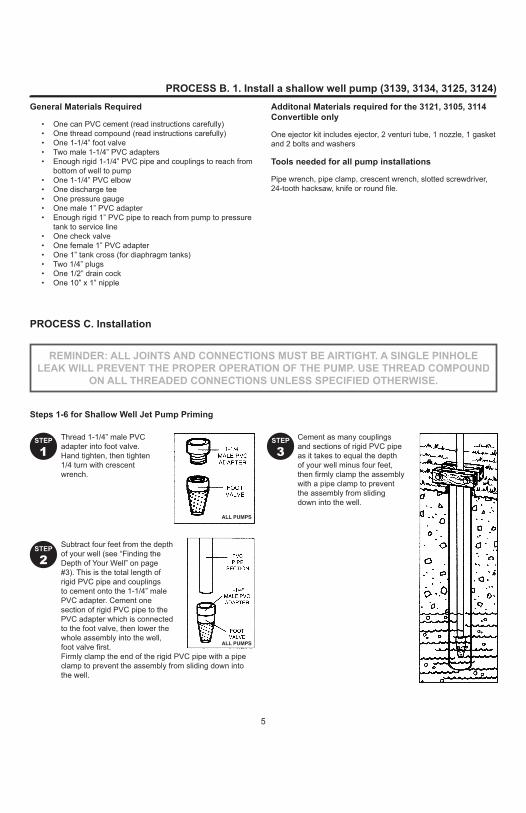
PROCESS B. 1. Install a shallow well pump (3139, 3134, 3125, 3124)General Materials Required
• One can PVC cement (read instructions carefully)• One thread compound (read instructions carefully)• One 1-1/4” foot valve• Two male 1-1/4” PVC adapters• Enough rigid 1-1/4” PVC pipe and couplings to reach from
bottom of well to pump• One 1-1/4” PVC elbow• One discharge tee• One pressure gauge• One male 1” PVC adapter• Enough rigid 1” PVC pipe to reach from pump to pressure
tank to service line• One check valve• One female 1” PVC adapter• One 1” tank cross (for diaphragm tanks)• Two 1/4” plugs• One 1/2” drain cock• One 10” x 1” nipple
Additonal Materials required for the 3121, 3105, 3114 Convertible only
One ejector kit includes ejector, 2 venturi tube, 1 nozzle, 1 gasketand 2 bolts and washers
Tools needed for all pump installations
Pipe wrench, pipe clamp, crescent wrench, slotted screwdriver, 24-tooth hacksaw, knife or round file.
REMINDER: ALL JOINTS AND CONNECTIONS MUST BE AIRTIGHT. A SINGLE PINHOLELEAK WILL PREVENT THE PROPER OPERATION OF THE PUMP. USE THREAD COMPOUND
ON ALL THREADED CONNECTIONS UNLESS SPECIFIED OTHERWISE.
Thread 1-1/4” male PVC adapter into foot valve. Hand tighten, then tighten 1/4 turn with crescent wrench.
Subtract four feet from the depth of your well (see “Finding the Depth of Your Well” on page #3). This is the total length of rigid PVC pipe and couplings to cement onto the 1-1/4” male PVC adapter. Cement one section of rigid PVC pipe to the PVC adapter which is connected to the foot valve, then lower the whole assembly into the well, foot valve first. Firmly clamp the end of the rigid PVC pipe with a pipe clamp to prevent the assembly from sliding down into the well.
Cement as many couplings and sections of rigid PVC pipe as it takes to equal the depth of your well minus four feet, then firmly clamp the assembly with a pipe clamp to prevent the assembly from sliding down into the well.
STEP
1
STEP
2
STEP
3
PROCESS C. Installation
Steps 1-6 for Shallow Well Jet Pump Priming
6
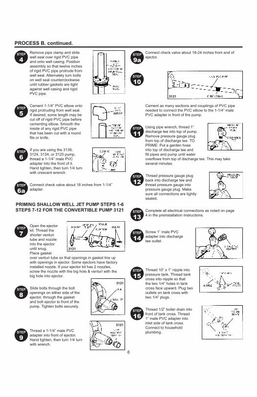
PROCESS B. continued.
Remove pipe clamp and slide well seal over rigid PVC pipe and onto well casing. Position assembly so that twelve inches of rigid PVC pipe protrude from well seal. Alternately turn bolts on well seal counterclockwise until rubber gaskets are tight against well casing and rigid PVC pipe.
Cement 1-1/4” PVC elbow onto rigid protruding from well seal. If desired, some length may be cut off of rigid PVC pipe before cementing elbow. Smooth the inside of any rigid PVC pipe that has been cut with a round file or knife.
If you are using the 3139, 3124, 3134, or 3125 pump, thread a 1-1/4” male PVC adapter into the front of it. Hand tighten, then turn 1/4 turn with crescent wrench.
Connect check valve about 18 inches from 1-1/4” adapter.
Open the ejector kit. Thread the shorter venturi tube and nozzle into the ejector until snug. Place gasket over venturi tube so that openings in gasket line up with openings in ejector. Some ejectors have factory installed nozzle. If your ejector kit has 2 nozzles, screw the nozzle with the big hole & venturi with the big hole into ejector.
Slide bolts through the bolt openings on either side of the ejector, through the gasket and bolt ejector to front of the pump. Tighten bolts securely.
Thread a 1-1/4” male PVC adapter into front of ejector. Hand tighten, then turn 1/4 turn with wrench.
Connect check valve about 18-24 inches from end of ejector.
Cement as many sections and couplings of PVC pipe needed to connect the PVC elbow to the 1-1/4” male PVC adapter in front of the pump.
Using pipe wrench, thread 1” discharge tee into top of pump. Remove pressure gauge plug from top of discharge tee. TO PRIME: Put a garden hose into top of discharge tee and fill pipes and pump until water overflows from top of discharge tee. This may take several minutes.
Thread pressure gauge plug back into discharge tee and thread pressure gauge into pressure gauge plug. Make sure all connections are tightly sealed.
Complete all electrical connections as noted on page 4 in the preinstallation instructions.
Screw 1” male PVC adapter into discharge tee outlet.
Thread 10” x 1” nipple into pressure tank. Thread tank cross into nipple so that the two 1/4” holes in tank cross face upward. Plug two outlets on tank cross with two 1/4” plugs.
Thread 1/2” boiler drain into front of tank cross. Thread 1” male PVC adapter into inlet side of tank cross. Connect to household plumbing.
STEP
4
STEP
10
PRIMING SHALLOW WELL JET PUMP STEPS 1-6STEPS 7-12 FOR THE CONVERTIBLE PUMP 3121
STEP
5
STEP
6
STEP
7
STEP
8
STEP
9
STEP
11
STEP
12
STEP
13
STEP
14
STEP
15
STEP
16
STEP
6a
STEP
9a
7
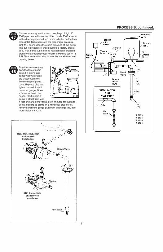
PROCESS B. continued.
Cement as many sections and couplings of rigid 1” PVC pipe needed to connect the 1” male PVC adapter in the discharge tee to the 1” male adapter on the tank cross inlet. Set pressure in the diaphragm pressure tank to 2 pounds less the cut-in pressure of the pump. The cut-in pressure of these pumps is factory preset to 20 PSI. If this cut-in setting has not been changed, then the diaphragm pressure tank should be set to 18 PSI. Total installation should look like the shallow well drawing below.
To prime, remove plug from the top of pump case. Fill piping and pump with water until the water overflows from the top of pump case. Replace plug and tighten to seal. Install pressure gauge. Open a faucet or two in the house. Start motor. If pump is offset from well 4 feet or more, it may take a few minutes for pump to prime. Failure to prime in 5 minutes: Stop motor, remove pressure gauge plug from discharge tee, add more water, try again.
STEP
17
STEP
18
3139, 3134, 3125, 3124Shallow Well Installation
3121 ConvertibleShallow Well Installation
Ejector
Foot Valve
Check Valve
# 3139# 3134# 3125# 3124
CheckValve

8
PROCESS B. 2. Install a shallow well convertible pump (3121)DEEP WELL PUMP INSTALLATION(4” DIAMETER CASED WELL)
For wells over 25, but not exceeding 80 feet in depth, the 1 HP 3114 Convertible Deep Well pump is recommended. However, the 3105 Deep Well Pump may also be used for depths not exceeding 70 feet.
General materials needed for the 3121, 3105 or 3114 convertible pumps
• One can PVC cement (read instructions carefully)• One thread compound (read instructions carefully)• Two 1“ female PVC adapters• Enough rigid 1-1/4” PVC pipe and couplings to reach from
bottom of well to pump (delivery pipe)• One 1-1/4” PVC elbow• One 1-1/4” male PVC adapter• One pressure regulator• One pressure gauge• Two male 3/4” PVC adapters• One check valve
• Enough rigid 3/4” PVC pipe to reach from pump to pressure tank to service line
• Tank tee (for diaphragm tanks)• Two 1/4” plugs• One 1/2” drain cock
Additional materials needed for the 3121, 3105, 3114 Convertibles
• One 1-1/4” foot valve• One 1-1/4” close nipple• One ejector• One 1” x 5” nipple• One 1-1/4” female adapter• One well seal• Enough rigid 1” PVC pipe and couplings to reach from
bottom of well to pump (pressure pipe)• One 1” PVC elbow• Two 1-1/4” male PVC adapters• One 1” x 4” nipple
REMINDER: ALL JOINTS AND CONNECTIONS MUST BE AIRTIGHT. A SINGLE PINHOLELEAK WILL PREVENT THE PROPER OPERATION OF THE PUMP. USE THREAD COMPOUND
ON ALL THREADED CONNECTIONS UNLESS SPECIFIED OTHERWISE.
Thread 1-1/4” close nipple into foot valve. Thread the other end of 1-1/4” close nipple into bottom of twin ejector. Hand tighten, then tighten 1/4 turn with pipe wrence.A. Some ejectors have a factory
installed brass nozzle.B. If nozzle is in ejector kit,
thread nozzle with small hole into 1-1/4” opening, then thread long venturi with small hole for deep well into the 1-1/4” opening.
The ejector has two holes in the top of it. Thread deep well venturi tube (part #2 - longer tube) into larger hole until snug. Thread 1” x 5” nipple into smaller hole. Only hand tighten venturi tube. Hand tighten nipple 1/4 turn with pipe/ crescent wrench.
Thread a 1-1/4” male PVC adapter over the venturi tube and into ejector. Thread a 1” female PVC adapter onto the 1” x 5” nipple. Hand tighten adapters 1/4 turn with pipe/crescent wrench.
Subtract five feet from the depth of your well. This is the total length of PVC pipe and couplings to cement onto both 1-1/4” male and 1” female PVC adapters. Cement a section of PVC pipe to each adapter, then lower the whole assembly into the well, foot valve first. Firmly clamp the end of the PVC pipes with a pipe clamp to prevent the assembly from sliding down into well.
STEP
1
STEP
2
STEP
3TO INSTALL THE 3105, 3114 CONVERTIBLE PUMP
STEP
4
9
PROCESS B. continued. - Convertible Pump
Cement as many couplings and sections of rigid PVC pipe on both the pressure and delivery sides as it takes to equal the depth of your well minus four feet, then firmly clamp the assembly with a pipe clamp to prevent the assembly from sliding down into the well. Be sure to keep track of which pipe is the pressure pipe and which is the delivery pipe.
Remove pipe clamp and slide well seal over PVC pipes and onto well casing. DO NOT let assembly slide down into well. Position assembly so that twelve inches of PVC pipes protrude from well seal. Using crescent wrench, turn bolts on well seal counterclockwise until rubber gaskets are tight against the well casing and the PVC pipes.
Cut 1” pipe 2” shorter than the 1-1/4” pipe. Smooth rough edges. Cement 1” and 1-1/4” PVC elbows to pipes protruding from the well seal.
Thread a 1-1/4” male PVC adapter into top hole in front of pump. Thread 1” x 4” nipple into bottom hole in front of pump. Thread the 1” female PVC adapter onto the 1” x 4” nipple.
Connect check valve to delivery pipe about 18-24 inches from ejector end.
Open pressure regulator kit (purchased separately). With pipe wrench, thread the pressure regulator into 1” discharge at top of pump. Thread pressure gauge into side of pump case.
Thread plug into opening to right of pressure regulator outlet.
Complete all electrical connections as specified on page 4 in the preinstallation instructions.
Thread 3/4” male PVC adapter into pressure regulator outlet.
Thread tank tee into diaphragm pressure tank. Plug two outlets on tank tee with two 1/4” plugs.
Thread boiler drain into front of tank tee. Thread 3/4” male PVC adapter into inlet side of tank tee. Connect to household plumbing.
TO PRIME: Remove pressure regulator, put a garden hose into the top of the pump discharge and fill and pump with water until water overflows from top of pump. This may take several minutes. Put regulator back on pump.
STEP
10
PRIMING CONVERTIBLE DEEP WELL JET PUMPS3105, 3114
STEP
5
STEP
6
STEP
7
STEP
8
STEP
9
STEP
11
STEP
12
STEP
13
STEP
14
STEP
15
STEP
16
Cement as many sections and couplings of rigid 1” and 1-1/4” PVC as needed to connect the 1” female PVC adapter and the 1-1/4” male adapter to the 1” and 1-1/4” PVC elbows.
STEP
9a

10
PROCESS B. continued. - Convertible
Cement as many sections and couplings of rigid PVC pipe needed to connect the PVC adapter in the discharge tee to the male adapter on the tank tee inlet. Set pressure in the diaphragm pressure tank to 2 pounds less than the cut-in pressure of the pump. The cut-in pressure of these pumps is factory preset to 18 PSI. If this cut-in setting has not been changed, then the diaphragm pressure tank should be set to 18 PSI. Total installation should look like drawing at right.
Open a faucet or two in the house. Start motor. Turn regulator adjustment screw down tight. If pump is properly primed, a high pressure will immediately show on the pressure gauge. With pump operating at high pressure, slowly unscrew regulator stem until maximum water flow is obtained without dropping to zero. If no pressure shows, stop motor, remove pressure regulator from pump, add more water, and try again.
STEP
17
STEP
17
WARNING Risk of explosion. If you change pressure switch settings, set the cut-off pressure low enough to shut off the pump. If the valve shuts off and the cut-off setting is too high,
the pump will run continuously without water flow, causing overheaating and possible explosion which can cause serious burns and damage.
DRAINING FOR SERVICING OR FOR WINTER
The pump should be drained before it is disconnected for servicing or if it is in danger of freezing. To drain:
• Remove drain plug from bottom of pump case.• Remove discharge tee to vent the pump.• Drain all piping to a point 3 feet (1 meter) below
ground level.
For wells 25 feet or less in depth, the 1/2 HP, 3/4 HP and 1 HP pumps are recommended. However, the 3/4 HP and 1/2 HP convertible pumps may be adapted to shallow wells with ejector kit.
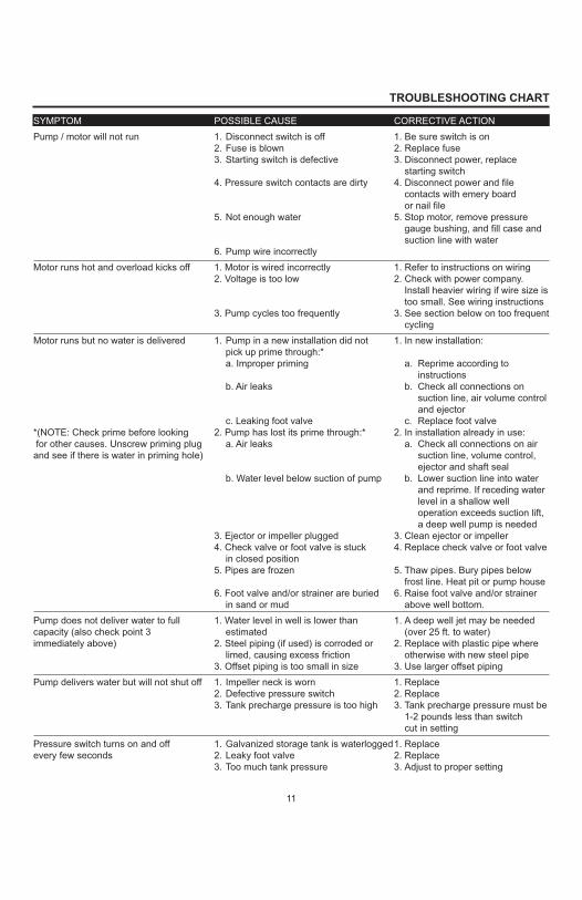
TROUBLESHOOTING CHART
SYMPTOM POSSIBLE CAUSE CORRECTIVE ACTIONPump / motor will not run 1. Disconnect switch is off 1. Be sure switch is on
2. Fuse is blown 2. Replace fuse3. Starting switch is defective 3. Disconnect power, replace starting switch4. Pressure switch contacts are dirty 4. Disconnect power and file contacts with emery board or nail file5. Not enough water 5. Stop motor, remove pressure gauge bushing, and fill case and suction line with water6. Pump wire incorrectly
Motor runs hot and overload kicks off 1. Motor is wired incorrectly 1. Refer to instructions on wiring2. Voltage is too low 2. Check with power company. Install heavier wiring if wire size is too small. See wiring instructions3. Pump cycles too frequently 3. See section below on too frequent cycling
Motor runs but no water is delivered 1. Pump in a new installation did not 1. In new installation:pick up prime through:*a. Improper priming a. Reprime according to
instructionsb. Air leaks b. Check all connections on
suction line, air volume control and ejector
c. Leaking foot valve c. Replace foot valve*(NOTE: Check prime before looking 2. Pump has lost its prime through:* 2. In installation already in use: for other causes. Unscrew priming plug a. Air leaks a. Check all connections on air and see if there is water in priming hole) suction line, volume control,
ejector and shaft sealb. Water level below suction of pump b. Lower suction line into water
and reprime. If receding water level in a shallow well operation exceeds suction lift, a deep well pump is needed3. Ejector or impeller plugged 3. Clean ejector or impeller4. Check valve or foot valve is stuck 4. Replace check valve or foot valve
in closed position5. Pipes are frozen 5. Thaw pipes. Bury pipes below frost line. Heat pit or pump house6. Foot valve and/or strainer are buried 6. Raise foot valve and/or strainer
in sand or mud above well bottom.Pump does not deliver water to full 1. Water level in well is lower than 1. A deep well jet may be needed capacity (also check point 3 estimated (over 25 ft. to water)immediately above) 2. Steel piping (if used) is corroded or 2. Replace with plastic pipe where
limed, causing excess friction otherwise with new steel pipe3. Offset piping is too small in size 3. Use larger offset piping
Pump delivers water but will not shut off 1. Impeller neck is worn 1. Replace2. Defective pressure switch 2. Replace3. Tank precharge pressure is too high 3. Tank precharge pressure must be 1-2 pounds less than switch cut in setting
Pressure switch turns on and off 1. Galvanized storage tank is waterlogged1. Replaceevery few seconds 2. Leaky foot valve 2. Replace
3. Too much tank pressure 3. Adjust to proper setting
11
12
ABC
DEF
A B C
D - Shallow Well Short Venturi Tube
E - Deep Well LongVenturi Tube
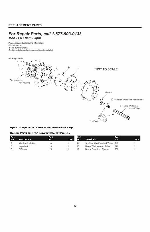
REPLACEMENT PARTS
For Repair Parts, call 1-877-903-0133Mon - Fri • 9am - 3pmPlease provide the following information:-Model number-Serial number (if any)-Part description and number as shown in parts list
Shallow Well Venturi Tube 210 1Deep Well Venturi Tube 220 1Black Cast Iron Ejector 230 1
Gasket
F - Ejector
*NOT TO SCALE
G - Motor Cap /Fan Housing
Housing Screws
Mechanical Seal 110 1Impellert 115 1Diffuser 120 1

13
PUMP DISASSEMBLY
REPAIR KITS FOR 3121, 3105, 3114, 3139, 3105, 3114, 3124 PUMPS
Impeller, Venturi, Nozzle & Diffuser Kit
Seal andGasket Kit
Pump Seal & Gasket Impeller & DiffuserModel HP Kit No. Kit No.
3121 1/2 A B
3105 3/4 A B
3114 1 A B
3139 1/2 A B
3134 3/4 A B
3125 1 A B
3124 1/2 A B
Terminal Box115/230 Voltage Switch Inside
Motor
O-Ring
Diffuser
Impeller
20/40Pressure Switch
000312100031050003114
20/40Pressure Switch
0003139000313400031250003124
O-Ring
Seals
Impeller
Diffuser
Venturi Tube
Nozzle
Venturi
Nozzle
ConvertibleJet Pumps
Shallow WellJet Pumps
Shallow WellJet Pumps
Only
Factory Installed Venturi and
Nozzle
WARRANTY
14
Printed in China
3 YEAR LIMITED WARRANTY. All pumps (0003139, 0003134, 0003125, 0003121, 0003105, 0003114, 0003124) covered in this manual, are warranted by the manufacturer to the original user against defects in workmanship or materials under normal use for 3 years after date of purchase. Any part which is determined to be defective in material or workmanship and returned to an authorized service location, as the manufacturer designates, shipping costs prepaid, will be, as the exclusive remedy, repaired or replaced at the manufacturer’s option. For limited warranty claim procedures, see PROMPT DISPOSITION below. This limited warranty gives purchasers specific legal rights which vary from jurisdiction to jurisdiction.LIMITATION OF LIABILITY. To the extent allowable under applicable law, the manufacturer’s liability for consequential and incidental damages is expressly disclaimed. The manufacturer’s liability in all events is limited to and shall not exceed the purchase price paid.WARRANTY DISCLAIMER. The manufacturer has made a diligent effort to provide product information and illustrate the products in this literature accurately; however, such information and illustrations are for the sole purpose of identification, and do not express or imply a warranty that the products are merchantable, or fit for a particular purpose, or that the products will necessarily conform to the illustrations or descriptions.Except as provided below, no warranty or affirmation of fact, expressed or implied, other than as stated in the “LIMITED WARRANTY” above is made or authorized by the manufacturer.PRODUCT SUITABILITY. Many jurisdictions have codes and regulations governing sales, construction, installation, and/or use of products for certain purposes, which may vary from those in neighboring areas. While the manufacturer attempts to assure that its products comply with such codes, it cannot guarantee compliance, and cannot be responsible for how the product is installed or used. Before purchase and use of a product, review the product applications, and all applicable national and local codes and regulations, and be sure that the product, installation, and use will comply with them.Certain aspects of disclaimers are not applicable to consumer products; e.g., (a) some jurisdictions do not allow the exclusion or limitation of incidental or consequential damages, so the above limitation or exclusion may not apply to you; (b) also, some jurisdictions do not allow a limitation on how long an implied warranty lasts, consequently the above limitation may not apply to you; and (c) by law, during the period of this limited warranty, any implied warranties of implied merchantability or fitness for a particular purpose applicable to consumer products purchased by consumers, may not be excluded or otherwise disclaimed.PROMPT DISPOSITION. The manufacturer will make a good faith effort for prompt correction or other adjustment with respect to any product which proves to be defective within limited warranty. Title and risk of loss pass to buyer on delivery to common carrier. If product was damaged in transit to you, file claim with carrier.

INFORMACIÓN GENERAL SOBRE SEGURIDAD
3. Antes de instalar este producto, haga que un electricista revise su circuito para asegurarse de la puesta a tierra sea adecuada.4. ASEGÚRESE de que la fuente de alimentación de la bomba esté desconectada antes de instalar o reparar la bomba.
eléctrica sea el mismo.
8. No haga funcionar la bomba en seco.
¡ADVERTENCIA! LEA Y COMPRENDA TODAS LAS INSTRUCCIONES.
Este manual contiene secciones importantes relacionadas con la seguridad del usuario, el uso de las herramientas, el mantenimiento de las herramientas, etc. Asegúrese de que este manual esté siempre incluido con la venta o alquiler del producto. Es una buena idea pedir copias adicionales para otros usuarios del producto. Se encuentran disponibles copias adicionales, gratuitas llamando al 1-877-903-0133.No seguir todas las instrucciones podría tener consecuencias fatales u ocasionar lesiones
graves. Lea, comprenda y siga todas las advertencias e instrucciones de seguridad que se proporcionan junto al producto. El incumplimiento de las instrucciones y advertencias podría ocasionar la muerte o lesiones personales graves.
PELIGRO: indica una situación de peligro inminente que, de no evitarse, ocasionará la muerte o lesiones graves.
ADVERTENCIA: indica una situación potencialmente peligrosa que, de no evitarse, puede ocasionar la muerte o lesiones graves.
PRECAUCIÓN: indica una situación de posible peligro que, de no evitarse, puede ocasionar lesiones menores o moderadas.
AVISO: indica información importante que, de no seguirse, podría resultar en daños para el equipo.
AVISO: Esta bomba no está diseñada para usar con agua salada, salmuera, descarga del lavado ni ninguna otra aplicación que pueda contener químicos cáusticos o materiales extraños. La bomba se puede dañar si se utiliza en estas aplicaciones y se anulará la garantía.
2. Conecte este producto a un circuito con conexión a tierra equipado con un interruptor de circuito de fallas de conexión a tierra (GFCI).
PELIGRO: Riesgo de descarga eléctrica. Esta bomba no es sumergible. Mantenga el motor seco en todo momento. No lave el motor. No lo sumerja. Proteja al motor del clima húmedo. No permita que ninguna parte del cable ni los extremos del receptáculo se apoyen en el agua ni en lugares húmedos. No seguir estas instrucciones puede provocar la muerte, lesiones graves o daños a la propiedad.
ADVERTENCIA: Riesgo de descarga eléctrica. Todo el cableado debe realizarlo un
locales y nacionales.
ADVERTENCIA: Riesgo de incendio/explosión. Bombee sólo agua limpia. No bombee
provocar la muerte, lesiones graves o daños a la propiedad.
16

Desembalaje
INFORMACIÓN GENERAL DE SEGURIDADLEA Y SIGA LAS INSTRUCCIONES DE SEGURIDAD.
ADVERTENCIA: Voltaje peligroso. Puede producir una descarga eléctrica, quemar o causar la muerte. Conecte la bomba a tierra antes de conectar al suministro de energía. Desconecte la alimentación antes de trabajar en la bomba, motor o tanque.
ADVERTENCIA: Presión peligrosa. Instale una válvula de descarga de presión en el tubo de descarga. Libere toda la presión en el sistema antes de trabajar en cualquier componente.
PRECAUCIÓN: No toque un motor en funcionamiento. Los motores están diseñados para funcionar a temperaturas altas. Para evitar quemaduras al reparar la bomba, deje que se enfríe durante 20 minutos después de apagarla antes de manipularla.
2. Bombee el agua solo con esta bomba.
ADVERTENCIA: El cuerpo de la bomba podría explotar si se utiliza como una bomba de reforzadora,
IMPORTANTE: Seguridad eléctrica
ADVERTENCIA: El voltaje del capacitor puede ser peligroso. Para desechar el capacitor del motor, sostenga un destornillador con manija aislante DE LA MANIJA y corte los terminales del capacitor juntos. No toque la cuchilla de metal del destornillador o los terminales del capacitor. Si tiene dudas, consulte con
códigos locales para todo el cableado.
eléctricas.
INFORMACIÓN GENERAL DE SEGURIDAD
17
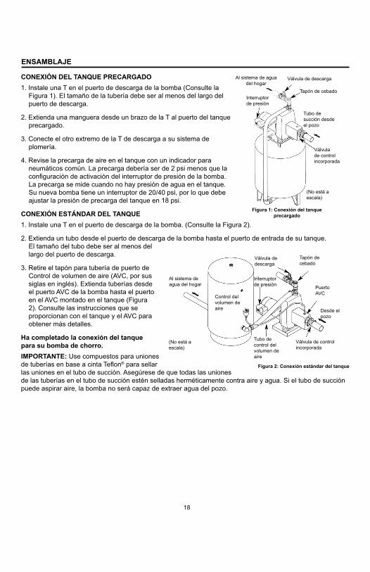
CONEXIÓN DEL TANQUE PRECARGADO1. Instale una T en el puerto de descarga de la bomba (Consulte la
puerto de descarga.
precargado.
3. Conecte el otro extremo de la T de descarga a su sistema de
4. Revise la precarga de aire en el tanque con un indicador para
Su nueva bomba tiene un interruptor de 30/50 psi, por lo que debe
CONEXIÓN ESTÁNDAR DEL TANQUE1. Instale una T en el puerto de descarga de la bomba. (Consulte la Figura 2).
2. Extienda un tubo desde el puerto de descarga de la bomba hasta el puerto de entrada de su tanque.
largo del puerto de descarga.
Control de volumen de aire (AVC, por sus
el puerto AVC de la bomba hasta el puerto en el AVC montado en el tanque (Figura 2). Consulte las instrucciones que se
obtener más detalles.
Ha completado la conexión del tanque para su bomba de chorro.IMPORTANTE: Use compuestos para uniones
® para sellar
ENSAMBLAJE
Figura 2: Conexión estándar del tanque
Figura 1: Conexión del tanque precargado
Al sistema de agua del hogar
Válvula de descarga
Tapón de cebadoInterruptor de presión
Tubo de succión desde
Válvula de control incorporada
(No está a escala)
Al sistema de agua del hogar
Válvula de descarga
Interruptor de presión Puerto
AVC
Desde el
Control del volumen de aire
(No está a escala)
Tubo de control del volumen de aire
Válvula de control incorporada
Tapón de cebado
20/4018
18

INSTALACIÓN
Instalación en un lago
malla (Consulte la Figura 5C).
Instalación eléctrica
ADVERTENCIA Conecte a tierra el motor antes de conectar al suministro eléctrico.
ADVERTENCIA Si no conecta a tierra el motor puede provocar una descarga eléctrica fatal o grave.
ADVERTENCIA No conecte a tierra en una línea de suministro de gas.
ADVERTENCIA Para evitar una descarga eléctrica fatal o peligrosa, apague el motor antes de trabajar en las conexiones eléctricas.
ADVERTENCIA El voltaje de alimentación debe estar entre el 10% del voltaje de la placa de datos. El voltaje incorrecto puede provocar un incendio o un daño grave en el motor, y se anula la garantía. Si tiene dudas,
ADVERTENCIA Para reducir el riesgo de descarga eléctrica, instale el motor y todos los componentes eléctricos sobre el nivel superior del sumidero. Esta bomba no es sumergible.
ADVERTENCIA Cumpla con los códigos eléctricos locales y nacionales para todo el cableado.
ADVERTENCIA No manipule la bomba o el motor de la bomba con las manos húmedas ni cuando esté
ADVERTENCIA Siga las instrucciones de cableado que se encuentran en este manual cuando conecte las líneas eléctricas.
IMPORTANTE: no utilice extensiones eléctricas ni empalme los cables. Las conexiones se deben hacer en la caja de
ADVERTENCIA Siempre desconecte la fuente de alimentación antes de llevar a cabo cualquier trabajo en el motor o cerca de éste, o en su carga conectada.
ADVERTENCIA Nunca haga funcionar la bomba en seco o contra una descarga cerrada. Si lo hace puede provocar que la bomba se sobrecaliente, dañando el sello y causando posiblemente quemaduras en las personas que manipulan la bomba. Llena la bomba con agua antes de empezar.
CABLEADO
PRECAUCIÓN
2. Retire la tapa del interruptor de presión para exponer los terminales de cableado.
a tierra del interruptor.
4. Conecte el cable del suministro eléctrico a los dos terminales del interruptor de presión
Figura 6).
6. Mueva el interruptor a la posición 115 V (Consulte la Figura 7).
Figura 5C: instalación en el lago
Tapón de cebado
Tubo de succiónVálvula de pie siempre sumergida
Válvula de pie pro-tegida con malla
para mantener la suciedad fuera del sistema
T de cebado
Figura 6
Figura 7
19

CUADRO DE REVISIÓN DE PROBLEMAS
PROBLEMA CAUSA(S) POSIBLE(S) ACCIÓN CORRECTIVA
El motor no funciona 1. El interruptor de desconexión está apagado
2. El fusible está fundido
4. Los contactos del interruptor de presión están sucios
muchas veces1. El motor está incorrectamente cableado
El motor funciona pero no saca agua
antes de buscar otras causas. Desatornille el tapón de cebado
cebado)
1. Al bombear en una nueva instalación no
a. El cebado incorrecto
c. La válvula de pie tiene una fuga2. La bomba perdió su cebado porque:*
succión la bomba
está atascada en la posición cerrada5. Los tubos están congelados
6. La válvula de pie o el coladero están enterrados en arena o barro
encendido2. Cambie el fusible
interruptor de arranque
contactos de la lima con una lima
1. Consulte las instrucciones de cableado
Instale un cableado más pesado si
de cableado
1. En una nueva instalación:
a. Vuelva a cebar de acuerdo a las instrucciones
c. Reemplace la válvula de pie
uso:
vuelva a cebar. Si el nivel del agua de retorno en el funcionamiento de
elevación de la succión, se necesita
4. Reemplace la válvula de control o la válvula de pie
5. Descongele los tubos. Entierre
congelación. Caliente la fosa o la casa de la bomba
coladero para que no estén en el
20

PIEZAS DE REPUESTO
Figura 3: ilustración de las piezas de reparación para las bombas de chorro para pozos no profundos
ADVERTENCIA
Riesgo de descarga eléctrica. La bomba se suministra con un conductor de puesta a tierra y un enchufe con puesta a tierra. Para reducir el riesgo de descargas eléctricas, asegúrese de que esté conectada a un tomacorriente debidamente puesto a tierra. Debido a que la unidad posee protección térmica, está diseñada para apagarse temporalmente en condiciones de sobrecalentamiento; por lo tanto, no se recomienda bombear líquidos extremadamente calientes.
PARA OBTENER INFORMACIÓN LLAME AL 1-877-903-0133, DE LUNES A VIERNES DE 9 A.M. A 3 P.M., HORA CENTRAL ESTÁNDAR, E INCLUYA EL # DE MODELO, EL NÚMERO DE SERIE (SI CORRESPONDE), UNA DESCRIPCIÓN Y EL NÚMERO DE PIEZA COMO SE MUESTRA EN LA LISTA DE PIEZAS
A
B
c
DE
F
#3124
I
H
G
Ref. # Descripción A Junta tórica / Boquilla / Kit Venturi B Difusor C Contratuerca / Kit de empaquetadura D Impulsor E Junta tórica F Sello mecánico G Manguera H Conector en T I Tanque
21

GARANTÍA
Impreso en China
LIMITACIÓN DE RESPONSABILIDAD.
EXENCIONES DE LA GARANTÍA. ilustrar de forma exacta los productos en su material impreso; sin embargo, tal información e ilustraciones son sólo para
IDONEIDAD DEL PRODUCTO.
las áreas vecinas. Aunque el fabricante intenta asegurar que sus productos cumplen con dichos códigos, no puede
ATENCIÓN RÁPIDA.
reclamación al transportista.
GARANTÍA LIMITADA DE AÑOS.3
3 s
22