NEW LIMITATION CHANGE TO - DTIC · Wagon drills used for open cut drillings at the entries. Jumbo...
32
UNCLASSIFIED AD NUMBER AD284694 NEW LIMITATION CHANGE TO Approved for public release, distribution unlimited FROM Distribution authorized to U.S. Gov't. agencies and their contractors; Administrative/Operational Use; Sep 1962. Other requests shall be referred to Naval Civil Engineering Lab., Port Hueneme, CA. AUTHORITY US Naval Construction Battalion Ctr ltr, 24 Oct 1974 THIS PAGE IS UNCLASSIFIED
Transcript of NEW LIMITATION CHANGE TO - DTIC · Wagon drills used for open cut drillings at the entries. Jumbo...

UNCLASSIFIED
AD NUMBER
AD284694
NEW LIMITATION CHANGE
TOApproved for public release, distributionunlimited
FROMDistribution authorized to U.S. Gov't.agencies and their contractors;Administrative/Operational Use; Sep 1962.Other requests shall be referred to NavalCivil Engineering Lab., Port Hueneme, CA.
AUTHORITY
US Naval Construction Battalion Ctr ltr,24 Oct 1974
THIS PAGE IS UNCLASSIFIED
UNCLASSIFIED
AD 2 84 694
~4Me
ARMED SERVICES TECHNICAL INFORMATION AGENCYARLINGTON HALL STATIONARLINGTON 12, VIRGINIA
UNCLASSIFIED

NOTICE: When government or other drawings, speci-fications or other data are used for any purposeother than in connection with a definitely relatedgovernment procurement operation, the U. S.Government thereby incurs no responsibility, nor anyobligation whatsoever; and the fact that the Govern-ment may have formilated, furnished, or in any waysupplied the said drawings, specifications, or otherdata is not to be regarded by implication or other-wise as in any manner licensing the holder or anyother person or corporation, or conveying any rightsor permission to manufacture, use or sell anypatented invention that may in any way be relatedthereto.
FOR OFFICIAL USE ONLY
TECHNICAL NOTE N-454
RAPID TUNNELING EQUIPMENT AND TECHNIQUES
20 September 1962
U. S. NAVAL CIVIL ENGINEERING LABORATORYPort Hueneme, California

RAPID TUNNELING EQUUHENT AND TECHNIQUES
Y-FOl5-11-.604
Type B Final Report
by
Douglas Taylor
ABSTRACT
A study of existing reports and information for commercialtunneling equipment and methods was conducted to provide infor-mation about rapid tunneling, and to determine which equipmentcan be adopted by naval construction forces at advanced basesto permit underground operations. An outline is given for amanual on rapid tunneling equipment and techniques.

INTRODUCTION
The Bureau of Yards and Docks, in consideration of the possibleuse of nuclear weapons against naval advanced bases, assigned TaskY-FO15-l-6o0 to the Naval Civil Engineering Laboratory to obtainbasic information on rapid tunneling equipment and techniques thatcan be adopted by naval construction forces to provide undergroundprotective construction at advanced base sites.
The task instructions call for the evaluation of existingreports and literature on the subject, search for and analysis ofexisting commercial type tunneling equipment, an outline of andplan for the preparation and completion of a manual on equipmentand techniques, and recommendation for any necessary additional work.
THE LITERATURE SURVEY
Rapid tunneling records abound because each tunneling efforthas been a challenge to the skill and ingenuity of men to tunnelfaster than has ever been done before. Often it has been achallenge of teamwork, with face crew pitted against face crew onthe same heading, or perhaps on opposing headings racing at snail-like pace toward each other, and trying to outdo one another interms of footage or rounds completed in each shift. Frequently,the outcome has been determined by some geological inconstancythat has hampered or accelerated the progress of one or the othergroup. Tunneling contractors can usually point with pride tosome constructional aspect that has become a record-breaking event.For this reason most tunneling equipment manufacturers can truth-fully claim some outstanding performance of equipment that hascontributed to at least one rapid tunneling record. These recordsare proclaimed in reports and advertising and usually cannot bebrought to a common denominator for comparison because of differ-ences in geological conditions and/or tunnel sizes.
Tunneling to provide underground protection against earlyWorld War II weapons is history to the Bureau of Yards and Docksand the construction battalions. The Bureau administered workfrom December 1940 to July 1943 for a six-million-barrel under-
ground fuel storage at Pearl Harbor. Twenty vaults in twoparallel rows were excavated. EBeh vault was 100 feet in dia-
meter and 250 feet high. Over •even miles of tunnels were
required for access and piping. From September 1942 to Dcccm-
ber 1943, 120 tunnels 240 feet long were gxcavated at Waikele
Gulch for underground ammunition storage.

In September 1942, the 6th Naval Construction Battalion usedair spades, air drills, and hand shovels to dig four tunnels atPagoda Hill, Guadalcanal, to place vital equipment underground assoon as possible to be safe from bombing and shelling3 Japanesecars were used on Japanese rails to remove the spoil.3
Tunneling to provide underground protection against nuclearweapon effects has been used limitedly within the United Statesfor a few key military installations. Notably at some missilelaunching sites where continuous borin& machines have been usedto cut underground personnel passages, and at the granite baseof Cheyenne Mountain in Colorado, where, since May 1961, about athird of a million cubic yards is being excavated by the cyclicdrill-blast-muck method for the underground headquarters of theNorth American Air Defense Command. The main rock chamber ofthis facility will house a three story structural steel buildingwith about 200,000 square feet of floor space. 5
Tunneling has been practiced extensively for many yearsthroughout Sweden to provide bomb-resistant underground factories,power plants, oil and gasoline storage chambers, and more recentlyfor civilian shelters. One shelter in Stockholm can hold 20,000people in an emergency, and it doubles as a 600 car garage inpeacetime. The saelter chamber is 1000 feet long, 57 feet wide,and 37 feet high. The cyclic tunneling method prevailed in allSwedish work.
Several studies of underground protection have been spon-sored by U. S. Government agencies. The Rand Corporation, inconnection with work for Air Force Contract No. AF 49 (368) -700, held the Second Protective Construction Symposium (DeepUnderground Construction) in March 1959 to provide informationabout the design and construction of underground facilities toresist nuclear weapon effects. (The First Protective Construc-tion Symposium was held in 1957 to determine the state of theart in protective construction, and to show the constrictionrequirements for the survival of vital installations.)'Atomic Defense Engineering Technical Study No. 28 reports 8 onthe vulnerability of underground protective construction.
Since tunneling is akin to mining, it is not surprisingtU EiIUi Lbat the Burcau of Mines, under a prioje-t ARFignmPntfrom the Army Corps of Engineers, wrote a report in 1951 onthe subject of underground excavations for military use in
forward and intermediate areas. 9 Then in 1957, this Bureau
prepared a classified engineering manual for the design of
underground installations in rock. 1 0 The 1951 report is
particularly important because the basic information fills
2

some of the requirements of this "rapid tunneling" task.
The Bureau of Mines conducts research and developmentin minerals and explosives technology to promote safe andhealthful working conditions in the minerals industries, toeducate mine personnel in safe practices, and to deviseacceptable standards of mining operations. 1 1 This workbrings them in close contact with the mining and tunnelingindustries and the related equipment manufacturers, andgives them first hand knowledge of the operating characteris-tics and comparative efficiencies of tunneling equipment andtechniques.
The Bureau of Mines, in its l951 report "UndergroundExcavation Methods and Equipwent,"ý' points out that under-ground excavating is usually performed with experiencedsupervision, and with methods and equipment designed fora somewhat specific condition. However, underground con-ditions vary widely and are difficult to predetermine; there-fore, tunneling equipment and practices are usually modifiedto suit each underground operation as the occasion demandsto provide efficient procedures. Further, it would beimpractical to describe all the methods and equipment forall underground conditions. The 1951 report is intended toserve as a guide.
The Bureau of Mines selected a tunneling method that,in 45 to 60 days, would be capable of excavating 43 200 cubicyards of rock (about 960 to 720 cubic yards per days in asingle level, room-and-pillar system. This would providethree entries, each 14 feet wide and 12 feet high, and tenstandardized rooms, each 35 feet wide, 175 feet long, and 12feet high, (about 61,000 square feet total floor space), undera minimum 85-foot overhead cover. Speed of excavation wasthe prime consideration, and standard commercial excavatingequipment for the cyclic drill-blast-muck method was selectedbherever possible. Special consideration was given to existingstandard Army equipment. The tentative tunneling equipment toperform this excavation in hard rock was estimated to be asgiven in Appendix A. With this equipment, entries could be
driven vith !1-1/2 degrees maximum incline (20 percent slope).It was stated that the equipment selected may not have been
used in this combination in practice although each item had
been used successfully in other combinations; therefore, some
items would be subject to modification or substitution
following trials.
3

The report described alternate methods for some phases of
the tunneling cycle, and in each case one method was selected
as the best for rapid excavation. The selected procedures
included the following:
1. Compressors placed at the surface and the compressed
air piped to the working faces..
2. Electric generators placed at the surface and cables
laid to lighting and other circuits.
3. Surface material and rock at the portal sites to be
removed as in quarrying to u:icover 35-foot facesfor the entries.
4. All entries driven simultaneously and each ventilatedby a blower and vent pipe. After the first crosscuthas been driven to connect the entries, the blowers
are moved to the working faces and a ventilating fan
is installed in a bypass around a two-door airlock at
the center entry. Air circulates in at the centerand exhausts at the outer entries.
5. Sump pumps to remove drainage while driving the inclined
entries. Sumps to be excavated at the bottom of com-
pleted inclines, then the pumps are installed permanently.
6. The standard drilling round in headings to be a modified
burn cut ih preference to the wedge or pyramid cut.
(In a burn cut, several closely spaces holes are drilled
straight in. Some of them are loaded and the initial
blast breaks from these to the unloaded holes. In a
wedge cut, pairs of holes are angled to meet in a vee,
several vees form a wedge. In a pyramid cut, four
holes are drilled at an angle to meet at a common
point. The wedge or pyramid breaks out with the
initial.blast to provide an opening to break into
from delayed blasts in surrounding reliever and trim
cut holes.) In the selected modified burn cut, the
first reliever holes are angled as a narrow wedge,
and the next relievers angled as in a pyramid. Delay
electric blasting caps are used, and the number and
spacing of the drill holcs and amount of explosives
are determined from the rock conditions.

7. Wagon drills used for open cut drillings at the entries.Jumbo mounted drifter drills with feed shells for li-footsteel changes to drill headings and rooms. Jackhammersfor secondary drilling to blast large blocks left by theprimary rounds. Stoper drills for roof bolt holes.
8. Headings enlarged t~o room size by slabbing. Blast holesdrilled with 11-foot and 20-foot steel.
9. Water tanks on diesel powered trucks to supply water (ifit is not readily available at the surface) to pipe toJumbo manifolds for the drills and to wet down the muckwhile loading.
10. Blasting methods and safety precautions as given inDupont's "Blaster's Handbook.."
11. Thorough scaling (barring down) of all loose rock aftereach blast with scaling bars and gads from safe groundtoward loose ground.. (An oft repeated but often violatedrule. About 60 percent of all nine fatalities are causedby rock fall, with more than 40 percent occurring within25 feet of working faces).
12. Mucking by overcast loader at the face area into Koehring
"tDumptor"u type trucks because this equipment is bestsuited for forward and reverse travel and end loading inthe 14-foot by 12-foot headings. Trucks will enter atthe center and leave by an outside entry.
13. A minimum of roof support. it is assumed that the besttunneling ground will be selected., Large areas of badground encountered during tunneling will be bypassed,and small areas will be supported by roof bolts orcribbing.
14. General illumination to be supplied by 100-watt lamps
at 50-foot intervals, and floodlights at all workingareas.
The Bureau of Mines !ý)ýl report vuu judged to b1C a Ctisfactorysource of information for the most effective rapid tunnelingequipment and techniques at that; date.. So the literature survey
was directed toward finding improvements that have been intro-duced since the report was issued,, Information was examined
for cyclic and other methods.
5

There was a division of opinion among manufacturers contac-ted by the Laboratory on whether there have been any outstandingdevelopments in the tunne-ng field in the past several years.However, the annual reviews in mining journals report steadyimprovement in equipment and methods that have increased thespeed and economy of mining and tunneling.
Drilling
The improvement in drilling equipment is toward lightweightairleg drills for short rounds and jumbos with centralized con-
trols for long rounds. Within the last two years, most of theairleg drills have been changed to provide easily reached one-hand controls, increased drill blow frequency and impact, andincreased airleg pressureol2
The Swedish ladder drilling method, which has been adopted
in several countries, uses a retractable airleg drill mountedon a narrow steel ladder. The drill is carried in a cradlewhich slides along the ladder rails, and the airleg acts against
the rungs. It can be easily advanced or withdrawn. The advan-tages of this method over hand-held drills are a higher drillingrate, better control of position and direction, longer steelscan be used, two drills can be operated by one man, and withless operator fatigue)1 3 Several ladders mounted on a jumbo,present a simple low cost arrangement that approaches theefficiency of jumbos with hydraulically controlled drill booms.The hydraulic booms are being used extensively in this countryto replace the older hand adjusted jibs, Boom and drill con-trols on some jumbos have been centralized so that severaldrills can be operated simultaneously by one man. Cycle time
has been reduced because the time-consuming manual labor associ-
ated with spotting the drill to the hole pattern has been
eliminated.
Rotary percussion drills have been developed that have
hydraulic bit rotation and pneumatic bit impact Torque and
feed pressure can be varied separately to suit drilling con-
ditions. The best results are expected with slow bit rotation
and heavy bit impact in hard rock, and the opposite in softer
deposits. The drills can be jumbo-mountedol
The 13 -1/2-foot diameter, 44-mile long, West Delaware
tunnel for the New York City Board of Water Supply, which
was holed through in January 1960, was a proving ground for
some new tunneling methods and equipment. The two principal
6

contractors for this tunnel made the first extensive drillingwith large burn-cut holes in the drill pattern. One contractor
used two 5-inch holes, close together vertically, and drilled
by a Gardner-Denver Model 143 unit. The other contractor
drilled a single 8-inch hole with an Ingersoll-Rand modified
Model DHD-400 down-hole drill. With the large unloaded burn-cut holes, all other holes could be drilled parallel and 11-
foot rounds were pulled without steel changes. This drilling
arrangement eliminated the difficult and more precisely drilled
short angled holes required for the wedge-cut and pyramid-cut
patterns. It is believed that tunnels can be driven 20 to 30
percent faster with the large burn-cut holes, and with less
overbreak, more uck per round, and more concentrated muck with
less fly-rock. l, 15, 16 The latter contractor also used anIngersoll-Rand Fog Eliminator, a device which preheats the drill
air so that the air temperature will be above dewpoint when it
is exhausted from the drill and expands. This improved visi-bility ag the working face and increased the drillers' effi-
ciency.1
The American Mining Congress Underground Drilling Committee4
in a 1959 survey of the drilling practices of over 60 companies, ?
found that alloy drill steels were used by 49 percent and carbon
steel by 22 percent, the rest used both types. Most frequent
failures were at the shanks and metallurgical notchcs, and from
thread wear. However, drill steels are being improved constantly
to increase the total footage drilled per steel. Some alloy drill
steels are carburized and shot peened, and connection thread forms
have been changed to give longer wear and to make coupling and
uncoupling easier. Another development to eliminate stresses at
drill-steel collars that are Introduced during forging, upsetting,
and heat treatment is a rubber-lined collar that is bonded to the
steel shanks with epoxy cement. One company reorts triple in-
crease in footage for steels with this collar. These improve-
ments have increased cycle speed by reducing the frequency of
steel breakage.
The shock resistance of drill bits has been improved in
recent years by better heat treatment of bit bodies, and better
bonding of carbide inserts to the bodies. One manufacturer
notes that hole footage per bit has increased about 70 percent
in the last five years and bits cost lesso
The International Nickel Company in its mines near Sudbury,
Ontario, drills over 16,000,000 linear feet annually. They
maintain a Drilling Research Department to study drilling prac-
tices with an eye to increasing efficiency and reducing cost.
7

Drills, steels, and bits are tested for acceptance, and operatingand maintenance procedures are developed to extend the useful lifeof this equipment. One important finding was that bit insert lifecould be increased 80 percent when the insert was sharpened frommaximum dullness to half sharpness rather than to full sharpness,and loss of drilling speed was only 6 percent.3-° A choice mustbe made by the bit user for speed or economy.
A method for jet drilling blast holes has been used forseveral years in open pit drilling of taconite. The jet is arotating burner head which uses oxygen and kerosene to heat therock to 4200F. Watcr is fed through the jet stem to Lhe hot sur-face where it spalls the rock and generates steam to eject thechips. It produces a large irregular hole varying from 6-1/2inches up to an occasional 18-inch diameter; average about 9inches. Piercing rate averages about 17 feet per hour and burnerlife is about 10,000 hours. This compares with churn drill speedin taconite of 1 foot per hour and bit life of 100 minutes. 1 9 , 20
This method of drilling is not suitable for underground work.
Blasting
Ammonium nitrate-fuel oil (AN-FO) has been used for aboutfive years as an explosive for open pit mining and quarrying.Procedures are gradually being developed for extensive use under-ground. Ammonium nitrate is sold as prills, pellets and granules.It is not considered to be an explosive until a sensitizer isadded, usually 5 percent by weight of fuel oil, and this can bemixed at the site. AN-FO is highly soluble in water, but it canbe loaded in thin polyethylene tubing when holes are wet. Pneu-matic loading devices are available that force AN prills from astorage tank through a loading tube to the blast holes. Loadingtime is less than for dynamite, but static electricity, causedby movement of the prills through the tube, is a hazard. AN-FOblasting cfts are about 50 percent less than for other explo-sives.I•
Some blasters are experimenting with ammonium nitrateslurries which have high detonation velocitics suitable forhard rock blasting. The most common is 65 percent AN, 20 per-cent TNT, and 15 percent water. It is unaffected by water inthe blast hole. The slurries may permit a reduction in thesize and number of blast holes in a round,and thus decreasecycle time. Fume characteristics of AN-FO and the slurries,when compounded properly, are comparable to stanlard dynamite.12, 21
8

The Airdox system of blasting with 10,000 psi air, which isused in some coal mines, eliminates explosives and the zttendantfumes and danger. 2 2 The system would be adequate for some rockconditions, but it is not believed suitable for general use inunpredictable formations.
An electrothermal method for secondary breaking of rockshas been reported by Russians, and experiments with this methodare under way at the Montana School of Mines. Physical break iscaused by thermal breakthrough along the path of water trappedin the crystalline structure of rock when point electrodes areapplied and an electric current is passed through. The currentfrequency and voltage varies for different types of rock. Themethod is dustless, cheaper, and safer than blasting, but isstill in the developmental phase. 12' 23 Similarly, the Britishare experimenting with high-frequency radar waves which canproduce a wedge of heat to split rocks. It is almost noiseless,and the rock crumbles at hair-line cracks. For tunneling, wave-guides would be inserted in Rill holes at the working face thenthe energy would be applied.
Loading and Hauling
The size of the loading and hauling equipment will probablydetermine the tunnel cross-section dimensions (except where largeritems would be transported through or be stored in the completedunderground facility); therefore, they should be selected forminimum size consistent with the objective of excavating usefulunderground space efficiently, speedily, and safely. The minimumtunnel height would be determined by the height of the haulingvehicle cab, or by the maximum working height of the loader, whichin turn would depend upon the dump body height of the haulingvehicle. If a loader is selected that can load and unload withoutturning around, such as the rocker or overcast type, the minimumtunnel width will probably depend upon the hauler. The EINCOModel 630 Tractor-Excavator loads 3 tons per minute in about 11-foot headroom and 6-foot width, and the EIMCO Model 635 ContinuousLoader is rated at 4 tons per minute in about 9-foot headroom and6-foot width. Both can be obtained with air or electric drives.
Several available diesel powered carriers can be made suit.-able for underground hauling by the addition of exhaust scrubbers.The 10-ton capacity Koehring WD 60 Dumptor and Euclid 1UD have7-fcot 4-inch dump body height, about 9-foot 10-inch cab height,and about b-foot 3-inch over-all width. Lake Shore, Incorporated,
9

manufactures 10, 15, and 24 ton, four-wheel-drive shuttle trucksthat can negotiate 40 percent grades, 30 percent side slopes, andmake sharp turns. They have no cab,and dump body height is about6 feet. The Sanford-Day S-D Transloaders are versatile trans-ports that self-load, haul, and dump using a single operator. TheModel TL-45 has 4.5 cubic yard capacity, is 7-feet 10-inches wideand has 6-foot operating height. The Model TL-55 has 5.5 cubicyard capacity, is 7-feet 9-inches wide and has 8-foot operatingheight. Both have exhaust scrubbers,
Continuous Tunneling Machines
A survey of tunneling records shows that the continuousmethod using tunneling machines is faster than the cyclic methodin some geological conditions; notably in clay and shale whererates up to 2,600 cubic feet per hour have been found. Themachines are generally expensive. Qne machine for a 30-footdiameter tunnel cost over $500,000. '5 Because these machinesare used in soft materials, they are usually designed with ameans to line the tunnel with poured concrete or with precastconcrete or metal segments.
Some continuous mining machines can excavate undergroundspace faster than tunneling machines. A 7-foot diameter augerhas bored horizpntally into coal seams at about 4,200 cubicfeet per hour, 2 0 and the Joy Push Button Miner of the PeabodyCoal Company was designed to mine 4-feet high by 9-feet 9-inches wide to about 1,000-foot distance at about 6,400 cubicfeet per hour. 2 7
The Alkirk Corporation has developed the Alkirk Cycle Miner,a self-anchoring, pilot-pull, trepanning-type boring machinewhich is claimed to have a mining rate in sub-bituminous coalof 225 to 375 cubic feet per minute (13,500 to 22,500 cubic feet
per hour). This rate cannot be maintained because of the limitedcapacity of present loading and hbaling equipment to remove theloose coal from the working face.o
There is need for a continuous hard rock tunneling machine
that can economically match or surpass excavation rates of
about 500 cubic feet per hour achieved by the cyclic tunneling
method. At least two hard rock tunneling machines are being
planned.
10

Lake Shore, Incorporated, Iron Mountain, Michigan, has acompany-confidential program for the development of what isbelieved will be the fastest tunnel driving machine. Themanufacturer's literature will be available after the prototypehas been fully tested.
The Alkirk Corporation has made preliminary studies towardthe design of a hard rock tunneler which show that an effectivemachine could be built around the Alkirk Pilot-pull Principleusing rolling cutting tools similar to those for oil welldrills. The company is currentlý studying torque requirementsand other aspects of the deslgn.8
These developments should be watched although it isbelieved that tunneling machines would be too expensive andwould restrict tunnel configuration. They should not be con-sidered for tunneling at advanced bases except in an emergencyand where geological condittions would permit the use of existingtunneling machines (which are sometimes stored by contractorsfor potential modification for future tunnel work.) This equip-ment would complement cyclic tunneling equipment to providemaximum underground space in minimum time.
CUT-AND-COVER TUNNELS
The cut-and-cover method of tunneling, where a trench isdug and the underground tube is placed then covered with theexcavated material, is commonly used for the construction ofdrainage structures, sewers, and many subway tunnels. The sameconstruction techniques and equipment could be used for theinstallation of underground protective structures such as cattle-pass shelters. Similar work has been regular practice forMobile Construction Battalions In the construction of militarybases.
The U. S. Army Engineer Research and Development Labora-tories are considering a concept for a combat emplacementexcavator which can excavate about 400 cubic yards per hour.It is capable of cros8-country travel at speeds up to 25 mph,
and can be airlifted. 9 If this unit proves practical) itwould be a valuable asset to cut-and-cover construction work.
ll

ADVANCED BASE TUNNELING COMPONENT
The Bureau of Yards and Docks publication NAVDOCKS P103,30
Detailed Catalog of Yards and Docks Material for Advanced BaseFunctional Components, has several components and assemblieswith rock drilling and blasting capability.
Components P-1, Construction Battalion Large; P-5, Con-struction Battalion Maintenance Unit; P-8, Port DevelopmentEquipment; and P-21, Harbor Clearance Component; all containassemblies of rock drilling equipment and rock blasting con-sumables. These assemblies were recently revised to providenew equipment and materials. Assembly 7052, Rock DrillingEquipment - 75 TPH replaces Assemblies 7053, Rock DrillingEquipment - 30 CY-HR and 7054, Rock Drilling Consumables forI Wagondrill, 6 sinkers. Assembly 7055, Rock Blasting Con-sumables for 22,000 CY Rock has been revised to 45,000 tons.The P-4B Rock Drilling and Blasting Component supplementsthe combined P-1 and P-4 components on a large rock Job. Itis capable of producing about 200 000 tons of medium hardnessquarry rock at 200 tons per hour.1 This component was revisedrecently to equip it with modern dvilling machines. The com-ponents and assemblies might be revised further to include theeconomical ammonium nitrate-fuel oil explosives.
In an emergency, some useful tunneling work could beaccomplished with the equipment and consumables in the com-ponents mentioned above, but a tunneling component should beplanned if the excavation of underground space is to becomestandard practice. The component should be based on AppendixA except where it can be improved by greater detail, or wherethe items can be replaced by more efficient equipment that hasbeen introduced since the Bureau of Mines issued its 1951report, "Underground Excavation Methods and Equipment."
The Liboratory's review of tunneling equipment indicatesthat consideration should be given to a Jumbo-mounted Swedishladder drilling arrangement which would use lightweight retract-able airleg drills and a large burn-hole drill for an economical
"and efficient arrangement, or Jumbo-mounted rotary percussion
drills on hydraulically-controlled drill booms for versatilityand speed in mixed' geological formations. The use of ammoniumnitrate-fuel oil explosives should also be considered.
12

9ANUAL FOR RAPID TUNNELING
Equipment alone will not generate rapid tunneling. It alsorequires skilled manpower, teamwork, and knowledge of the problems
that are apt to be encountered in tunneling.
The basic Navy Mobile Construction Battalion, within itsA-company, has a platoon, A-1, that is trained to do the drilling,blasting, loading, and hauling associated with quarry operations
using the P-AB Rock Drilling and Blasting Component. The P-4Bhas a rated output of 150 cubic yards of rock per hour of a size
that can be handled by 1-1/2 to 2-1/2 cubic-yard shovels. 3 2
Although the A-1 Platoon training covers operations similar to
those used for tunneling, it does not include the techniquesand safety requirements that are peculiar to the undergroundwork.. If tunneling is to become standard practice for the
Mobile Construction Battalions, the techniques and safety re-quirements would need to be added to training courses and shouldbe included in a manual on tunneling.
The Bureau has indicated a need for a manual on rapidtunneling equipment and techniques. Seemingly, it would ex-clude such things as the desirability, design, or economy ofunderground protection as related to fallout or blast protect-ion; the size and shape of rooms except as these affect tun-neling techniques and safety; or the living or storage arrange-ments in the completed underground spaces.
The manual should present all factors that will lead tothe rapid excavation of underground space, such as standardiz-ation of entries, crosscuts, and rooms; development of themaximum number of headings pimultaneously; and the mostefficient scheduling of equipment.
It is believed that the manual should be written along the
lines of the Bureau of Mines 1951 report, "Underground Excava-
tion Methods and Equipment." 9 It should contain a condensedversion'of Part I of that report to instruct Mobile Construct-
ion Battalion personnel in the identification of rocks and
other geological conditions pertinent to excavating competent
underground structures. Part II should be rewritten to Bureau
of Yards and Docks standards, and updated in regard to the
speedier and more efficient equipment selected for the advanced
base tunneling component and for the techniques introduced
since 1951. Part III could be eliminated except, perhaps,
for the glossary. A suggested outline is given in Appendix B.
13

CONCLUSIONS
If the excavation of protective underground space becomesstandard practice for the Construction Battalions, it will benecessary to provide (1) an advanced base functional componentfor tunneling (2) a manual for tunneling equipment and tech-niques and (3M revision of the existing Construction Battaliontraining courses in drilling and blasting to cover the equipment,techniques, and safety requirements that are peculiar to under-ground work.
The Bureau of Mines 1951 report, "Underground ExcavationMethods and Equipment," 9 provides an excellent basis for (i) anadvanced base tunneling component, and (2) a manual for tunnelingequipment and techniques, but it should be updated in respect toimprovements that have been introduced since 1951, particularlyin drilling and blasting.
14

REFERENCES
1. Building the Navy's Bases in World War II, Vol II, U. S.Government Printing Office, Washington, D. C., 1947, p 134.
2. Ibid. p 147.
3. Ibid. p 244.
4. Tiptoe Through the Foothills." Western Construction,
Vol 35, No. 10, (Oct 1960), p 34
5. "Builders Blast Out Underground Fortress." EngineeringNews-Record, Vol 167, No. 20, (16 Nov 1961), p 38.
6. Westerberg, G. "Building Underground Pays in Sweden."Engineering News-Record, Vol 153, No. 24, (9 Dec 1954), p 33.
7. The Rand Corporation. Report No. R-341, Proceedings ofthe Second Protective Construction Symposium (Deep UndergroundConstruction), Vol 1 and I1, compiled by J. J. O'Sullivan,Santa Monica, Calif., 24-26 Mar 1959.
8. Christensen, W. J. "Vulnerability of Underground ProtectiveConstruction." The Navy Civil Engineer, Vol 1, No. 2, (Mar 1960),pp 39-48.
9. Bureau of Mines. Underground Excavation Methods and Equip-ment, by J. C. Hill and B. J. Anderson, Pittsburgh, Pa., Oct 1951.
10. Bureau of Mines. An Engineering Manual on Design of Under-ground Installations in Rock. Pittsburgh, Pa., March 1957.CONFIDENTIAL
11. General Services Administration. U. S. Government Organi-zation Manual 1960-61. Washington, D. C., I June 1960, p 244.
12. Boyd, Benton. "Underground Mining Progress." MiningCongress Journal, Vol 48, No. 2, (Feb 1962), p 62.
13. Atlas Copco. Publication No. 5050, The Swedish LadderDrilling Method. Stockholm, Sweden, 1960.
14. "Two Contractors Prove Out New Hard Rock Tunneling Method."Engineering News-Record, Vol 160, No. 26, (26 June 1958), P 28.
15

15. "44 Miles of Rock Tunnel Holed Thru." Engineering News-
Record, Vol 164, No. 2, (14 Jan 1960), p 21.
16. Ingersoll-Rand. Form 4213, 1960
17. Stewart, Raymond M. "Underground Drilling Practices." MiningCongress Journal, Vol 45, No. 4, (Apr 1962), p 63.18. Dewey, J. H. "Underground Drilling at Inco." Mining CongressJournal, Vol 47, No. l, (Jan 1961), p 24.
19. Erickson, Floyd W. "Drilling and Blasting Taconite." MiningCongress Journal, Vol 45, No. 1, (Jan 1959), P 37.
20. Bickel, F. D. "Developments in Taconite Blasting at Erie."Mining Congress Journal, Vol 47, No. 11, (Nov 1961), p 44.
21. Smith, Gordon R. "Blasting - New Materials, New Techniques."Construction Methods, Vol 44, No. 6, (June 1962), p 108.
22. McQuade, J. L. "Shooting with Air in Low Coal." MiningCongress Journal, Vol 47, No. 12, (Dec 1961), p 31.
23. Kravchenko, V. S., et al. "Dustless Breaking of rocksElectrically." Mining Congress Journal, Vol 47, No. 5;(May 1961), p 53.
24. "Radar Crumbles Rock and Concrete in U. K." Missiles andRockets, Vol 10, No. 17, (23 Apr 1962), p 21.
25. "A 'Hybrid Mole' Wraps up Oshe Tunnels." Engineering News-Record, Vol 166, No. 15, (13 Apr 1961), p 56.
26. Zager, L. F. "Auger Mining Standards and Comparative Costs."Mining Congress Journal, Vol 48, No. 1, (.Jan 1962), p 21.
27. Kirk, R. E., et al. "Underground Bituminous Coal Mining."Mining Congress Journal. Vol 48, No. 2, (Feb 1962), p 50.
28. Alkirk Corporation. Report on the Alkirk Pilot-PullPrinciple. Seattle, Washington
29. Caterpillar Tractor Co. Form 726-34519, Concept ProgressReport, Peoria, Illinois.
16

30. Bureau of Yards and Docks. NAVDOCKS P-103, DetailedCatalog of Bureau of Yards and Docks Material for AdvancedBase Functional Components, Washington, D. C.
31. Office of the Chief of Naval Operations. OPNAVINSTRUCTION 04040.22B, Catalogue of Advanced Base FunctionalComponents, Eighth Edition, Washington, D. C., 2 November1959.
32. Bureau of Yards and Docks. NAVDOCKS P-315, MobileConstruction Battalion Administration. Washington, D. C.,November 1959. P 5.
17

Appendix A
BUREAU OF MINES TENTATIVE TUNNELING EQUIPMENT TO EXCAVATE 43,200CUBIC YARDS OF HARD ROCK IN 45 TO 60 DAYS. 9
Item quantity Drilling Equipment and Supplies
1. 4(1)* Jumbo. A medium size crawler type diesel±
tractor with mounted framework and platformfor 5 ppdestals, hydraulic controlled booms,and 11-foot feed shells; water and air mani-folds with automatic line oilers for drifterdrills; racks for drill steel, spare hose,blow pipes, bits, ana small tools; and flood-lights with cable and a 200-foot capacity reel.
2. 20(8) Drifter drill, 3-inch, pneumatic, automaticfeed, chucked for 1-1/4-inch hollow roundlugged drill-steel. To be mounted on Jumbowith necessary hose and fittings.
3. 6 'Jackhammer drill, 55-pound, chucked for 3-inch hollow hexagonal steel. (Army standardequipment.)
4. 2(1) Stoper drill, 2-3/4-inch, self rotating,3-foot feed, chucked for 1-inch hollowhexagonal steel.
5. 6(1) Wagon drill, 4-inch, 6-foot feed, chuckedfor 1-1/4-inch hollow round lugged steel.(Army standard equipment.)
6. 5(2) Compressor, 600 cfm, rotary, diesel± driven,portable.
7. l(1) Water pump, 100 gpm at 60 psi water pressureat the drills.
8. 4(1) Water truck, diesel± powered, 1000 gallontank. (Alternate source for water when itis not available for pumping from surface.)
18

9. 3,000 feet Pipe, 4-inch light weight, 20-foot lengths.
Include quick-connect couplings such asDresser, Victaulic, or wedge lock. (Forcompressed air.)
10. 3,000 feet Pipe, 2-inch standard, 20-foot lengths.Include quick-connect couplings similarto those on air lines. (For water.)
11. 1,000 feet Air hose, 4-inch, 50-foot lengths. (Toconnect main air line to jumbo.)
12. 1,000 feet Air hose, 1-inch, 50-foot lengths. (Forjackhammers and stopers.)
13. 1850 Rock bits, 1-5/8-inch, tungsten carbideinserts. (For drifter drills.)
14. 150 Rock bits, 1-1/2-inch, tungsten carbideinserts. (For jackhammers and stopers,and as follower bits in drifters.)
15. 1100 Drill steel, 1-1/4-inch hollow roundlugged, 11-foot lengths.
16. 265 Drill steel, 1-1/4-inch hollow round lugged,20-foot lengths.
17. 30 Drill steel, 1-inch hollow hexagonalshanked, 2-foot lengths.
18. 30 Drill steel, 1-inch hollow hexagonalshanked, 4-foot lengths.
19. 30 Drill steel, 1-inch hollow hexagonalshanked, 6-foot lengths.
20. 20 Drill steel, 1-inch hollow hexagonalunshanked, 3-foot lengths.
21. 20 Drill steel, 1-inch hollow hexagonalunshankcd, 6-foot lengths.
19

Blasting Equipment and Supplies
22. 71.5 tons Explosives, 60 percent ammonia gelatin,1-1/4 by 8-inch sticks, packed in 50-pound cases.
23. 9,500 Electric blasting caps, No. 6 strength,milli-second delays 0 through 10, 16-foot leg wires.
24. 9,500 Electric blasting caps, No. 6 strength,milli-second delays 0 through 10, 24-footleg wires.
25. 8,200 Electric blasting caps, No. 6 strength,milli-second delays 11 through 16, 16-foot leg wires.
26. 1(1) Blasting switch, safety type, 200 volt,60 amp. (Main line.)
27. 6(2) Blasting switch, safety type, 220 volt,60 amp. (Branch lines.)
28. 5,000 feet Wire, No. 8 B & S gage, single conductor,(5,000 feet) rubber covered, double braided, waterproof.
(For main blasting circuit.)
29. 35,000 feet Wire, No. 14 B & S gage, single conductor,rubber covered, double braided, waterproof.(For lead and bus wires.)
30. 30,000 feet Wire, No. 20 B & S gage, single conductor,rubber covered, double braided, waterproof.(For connecting wires.)
31. 50,000 Stemming bags, paper, 1-1/4-inch diameter,18-inch long.
32. 3(1) Blasting wagon, 4 wheel rubber-tiredtrailer with 6-foot high loading plat-ru.Lin, cayse.iLy for 250 puutids of explo-sives.
20

33. 30 tons Sand for stemming bags.
34. 4(4) Tamping stick, 1-1/4-inch diameter, 14-footlong.
35. 4(4) Tamping stick, 1-1/4-inch diameter, 24-foot
long.
Loading Equipment and Supplies
36. 4(2) Overcast type shovel, 1-yard capacity, mounted
on a crawler type dieselz tractor.
37. 3(1) Bulldozer.
Hauling Equipment and Supplies
38. 12(4) Trucks, 10 ton, diesel± powered, preferablysimilar to Koehring "Dumptor."
Ventilation Equipment and Supplies
39. 1 Main ventilating fan, 100,000 cfm at 0.5 inchwater gage pressure, axial flow propeller,
driven by a 20 hp electric motor.
40. 3(2) Auxiliary blower, 26,000 cfm at 3.5 incheswater gage pressure, axial flow propeller,driven by a 40 hp electric motor.
41. 1,500 feet Ventilating pipe, 36-inch diameter, light-weight, rigid or semi-rigid, equipped with
(1,000 feet) easily made connections.
42. 2(l) Ventilating doors, double swing, equipped'with a mechanical opening device. (To fit
air lock opening.)
43. 200 square Brattice cloth.yards
21
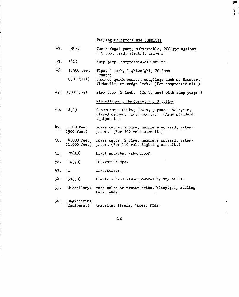
Pumping Equipment and Supplies
44. 3(3) Centrifugal pump, submersible, 200 gpm against125 foot head, electric driven.
45. 3(1) Sump pump, compressed-air driven.
46. 1,500 feet Pipe, 4-inch, lightweight, 20-footlengths.
(500 feet) Include quick-connect couplings such as Dresser,Victaulic, or wedge lock. (For compressed sir.)
47. 1,000 feet Fire hose, 2-inch. (To be used with sump pumps.)
Miscellaneous Equipment and Supplies
48. 2(1) Generator, 100 kw, 220 v, 3 phase, 60 cycle,diesel driven, truck mounted. (Army standardequipment.)
49. 1,500 feet Power cable, 3 wire, neoprene covered, water-(500 feet) proof. (For 200 volt circuit.)
50. 4,000 feet Power cable, 2 wire, neoprene covered, water-(1,000 feet) proof. (For 110 volt lighting circuit.)
51. 70(10) Light sockets, waterproof.
52. 70(70) 100-watt lamps.
53. 1 Transformer.
54. 50(50) Electric hand lamps powered by dry cells.
55. Miscellany: roof bolts or timber cribs, blowpipes, scalingbars, gads.
56. EngineeringEquipment: transits, levels, tapes, rods.
22

57. Basic machine shop (Army standard mobile field shop repairunit housed in a semitro'ler.)
Shop equipment (minimum): cutting and welding equipment;lathe; drill press; pipe threading machine; pedestal andbench grinders; rock bit grinder; chain blocks; wheelpullers; blacksmith equipment; electrician's tools, meters,and equipment; truck and tractor repair tools; hand tools.
58. Protective clothing for 150 men.
Notes: * Numbers in parentheses are additional items for spares.
± Diesel equipment must have electric starters andexhaust gas scrubbers.
23
I,
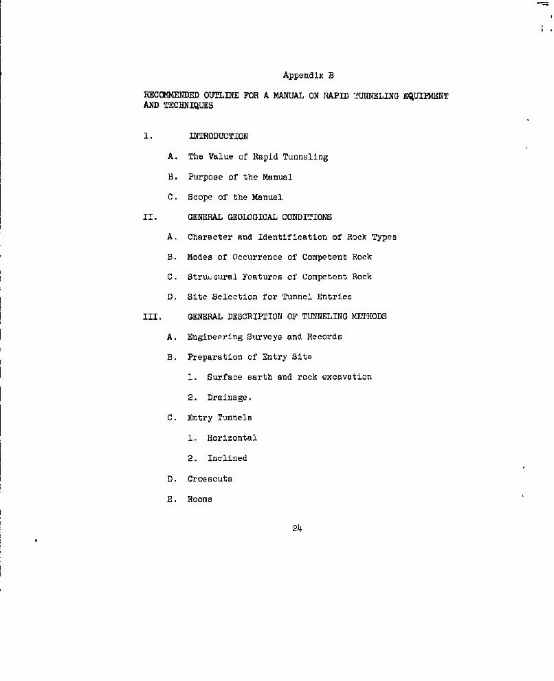
Appendix B
REC4MENDED OUTLINE FOR A MANUAL ON RAPID TUNNELING EQUIPMENTAND TECHNIQUES
1. INTRODUCTION
A. The Value of Rapid Tunneling
B. Purpose of the Manual,
C. Scope of the Manual
II. GENERAL GEOLOGICAL CONDITIONS
A. Character and Identification of Rock Types
B. Modes of Occurrence of Competent Rock
C. StruuGural Features of Competent Rock
D. Site Selection for Tunnel Entries
III. GENERAL DESCRIPTION OF TUNNELING METHODS
A. Engineering Surveys and Records
B. Preparation of Entry Site
1. Surface earth and rock excavation
2. Drainage.
C. Entry Tunnels
1. Horizontal
2. Inclined
D. Crosscuts
E. Rooms
24

F. Sumps
IV. DRILLING
A. Equipment
1. Drilling machines
2. Drill steel
3. Drill bits
4. Drill mountings and jumbos
B. Techniques
1. Drill round patterns
2. Drifting
3. Slashing
4. Benching
V. BLASTING
A. Equipment
1. Explosives and caps
2. Wires and switches
3. Stemming and tampers
4. Scaling tools
B. Techniques (including precautions)
1. Loading
2. Delay cap sequences
3. Wiring
25

4. Firing
5. Scaling down
VI. LOADING
A. Equipment
B. Techniques
VII. HAULING
A. Equipment
B. Techniques
VIII. ROOF SUPPORT
A. Bolting
B. Cribbing
IX. DRAINAGE
A. Pumps
B. Sumps
X. UTILITIES
A. Compressed air
1. Compressors
2. Piping
B. Electric Power
1. Generators
2. Wiring
3. Illumination
26

C. Water supply
1. Equipment
2. Installation
D. Ventilation
1. Auxiliary fans
2. Main fan
3. Fan room and Air Lock
4. Piping
X1. MISCELLANEOIJS EQUIPMENT
Xll. SAFETY MEASURES
APPENDIX A
Tunneling Component
Personnel
Equipment
APPENDIX B
Glousary