NEW LIMITATION CHANGE TO - Defense Technical ... AD NUMBER AD842823 NEW LIMITATION CHANGE TO...
83
UNCLASSIFIED AD NUMBER AD842823 NEW LIMITATION CHANGE TO Approved for public release, distribution unlimited FROM Distribution authorized to U.S. Gov't. agencies and their contractors; Administrative/Operational Use; Sep 1968. Other requests shall be referred to Air Force Materials Lab., Wright-Patterson AFB, OH. AUTHORITY AFML ltr, dtd 7 Dec 1972 THIS PAGE IS UNCLASSIFIED
-
Upload
trinhtuong -
Category
Documents
-
view
219 -
download
4
Transcript of NEW LIMITATION CHANGE TO - Defense Technical ... AD NUMBER AD842823 NEW LIMITATION CHANGE TO...

UNCLASSIFIED
AD NUMBER
AD842823
NEW LIMITATION CHANGE
TOApproved for public release, distributionunlimited
FROMDistribution authorized to U.S. Gov't.agencies and their contractors;Administrative/Operational Use; Sep 1968.Other requests shall be referred to AirForce Materials Lab., Wright-PattersonAFB, OH.
AUTHORITY
AFML ltr, dtd 7 Dec 1972
THIS PAGE IS UNCLASSIFIED

AFML-TR-67-420
FLIGHT TEST-WHIRLING ARM CORRELATIONOF RAIN EROSION RESISTANCE
OF MATERIALS
GEORGE F. SCHMITT, JR.
TECHNICAL REPORT AFML-TR-67-420
SEPTEMBER 1968
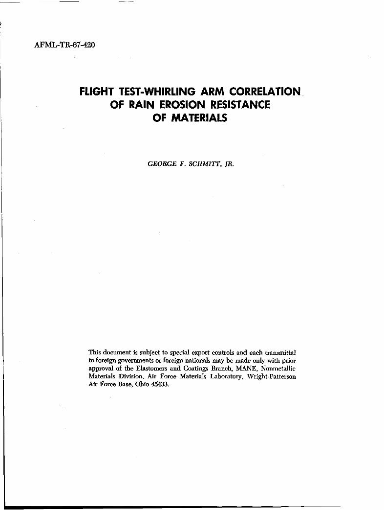
This document is subject to special export controls and each transmittalto foreign governments or foreign nationals may be made only with priorapproval of the Elastomers and Coatings Branch, MANE, NonmetallicMaterials Division, Air Force Materials Laboratory, Wright-PattersonAir Force Base, Ohio 45433.
AIR FORCE MATERIALS LABORATORYAIR FORCE SYSTEMS COMMAND
WRIGHT-PATTERSON AIR FORCE BASE, OHIO

NOTICE
When Government drawings, specifications, or other data are used for any purposeother than in connection with a definitely related Government procurement operation,the United States Government thereby incurs no responsibility nor any obligationwhatsoever; and the fact that the Government may have formulated, furnished, or inany way supplied the said drawings, specifications, or other data, is not to be regardedby implication or otherwise as in any manner licensing the holder or any other personor corporation, or conveying any rights or permission to manufacture, use, or sell anypatented invention that may in any way be related thereto.
This document is subject to special export controls and each transmittal to foreigngovernments or foreign nationals may be made only with prior approval of theElastomers and Coatings Branch, MANE, Nonmetallic Materials Division Air ForceMaterials Laboratory, Wright-Patterson Air Force Base, Ohio 45433.
The distribution of this report is limited because U. S. Export Control and isapplicable.
Copies of this report should not be returned unless return is required by securityconsiderations, contractual obligations, or notice on a specific document.
100- April 1970 - C0455 - 117-2565
AFML-TR-67-420
FLIGHT TEST-WHIRLING ARM CORRELATIONOF RAIN EROSION RESISTANCE
OF MATERIALS
GEORGE F. SCHMITT, JR.
This document is subject to special export controls and each transmittalto foreign governments or foreign nationals may be made only with priorapproval of the Elastomers and Coatings Branch, MANE, NonmetallicMaterials Division, Air Force Materials Laboratory, Wright-PattersonAir Force Base, Ohio 45433.

AFML-TR-67-420
FOREWORD
This report was prepared by the Elastomers and Coatings Branch, Non-metallic Materials Division, Air Force Materials Laboratory, Directorate ofLaboratories, Air Force Systems Command, Wright-Patterson AFB, Ohio. Thework was initiated under Project No. 7340 "Nonmetallic and Composite Ma-terials," Task No. 734007 "Coating for Energy Utilization, Control, andProtective Functions" and was administered under the direction of the AirForce Materials Laboratory, Mr. G. F. Schmitt, Jr., MANE, Project Engineer.
This report covers research conducted from February 1967 to June 1967 andwas submitted by the author in December 1967.
The author wishes to acknowledge the assistance of Captain Edward Millerof the Adverse Weather Branch, Deputy for Flight Test, Aeronautical SystemsDivision, in observing and recording the condition of the coatings after eachflight. The assistance of the personnel of the various industrial concerns whoapplied their respective coatings to the aircraft and of Mr. Roger Vissoc of theUniversity of Dayton Research Institute is also gratefully acknowledged.
This technical report has been reviewed and is approved.
W. P. 'ý-Jbnson, Acting ChiefElastomers and Coatings BranchNonmetallic Materials DivisionAir Force Materials Laboratory

AFML-TR-67-420
ABSTRACT
The exposure results of ten experimental rain erosion resistant coatings
on an F-100F aircraft which penetrated thunderstorms as part of the Project
Rough Rider flight tests have been correlated to whirling arm erosion simulation
results. The rankings of the erosion resistance of materials determined on the
whirling arm were similar for the same materials in actual flight exposures.
These flights confirmed the applicability and superiority of the electroplated
nickel and polyurethane coatings to protect aircraft leading edges and helicopter
rotor blades from the effects of rain erosion. Because the results from the
whirling arm technique and the flight tests were similar, the whirling arm is
considered to be a good research tool for exploratory development of rain erosion
resistant materials. These results reconfirm previous correlations of whirling
arm rain erosion results with aircraft flight tests.
(The distribution of this abstract is unlimited.)
iii

AFML-TR-67-420
TABLE OF CONTENTS
SECTION PAGE
I INTRODUCTION 1
II SUMMARY 2
III WHIRLING ARM APPARATUS 4
IV DESCRIPTION OF COATING APPLICATIONS 5
V EROSION RESULTS ON FLIGHT EXPOSURES 9
1. Data Collection 9
2. Erosion Results 9
a. Specification Black Neoprene(MIL-C-7439B) (Position B) 16
b. Clear Urethane (Position C) 16
c. Pigmented Urethane (Position D) 16
d. Clear Urethane (Position E) 17
e. Electroformed Nickel (Position F) 17
f. Y-9265 Urethane Tape (Position G) 18
g. Estane Boot (Position H) 18
h. Neoprene Boot (Position J) 18
i. Hycar Boot (Position K) 19
j. Deicing Boots (Position L) 19
k. P.O. 655 Urethane (Position A) 20
1. Nordel Ethylene-Propylene Rubber (Position M) 20
m. Neoprene With Nordel Backing (Position N) 20
n. Neoprene With Gum Rubber Backing (Position 0) 20
o. Nordel Ethylene-Propylene Rubber (Position P) 21
p. White Neoprene (Position Q) 21
VI COMPARISON OF WHIRLING ARM ANDFLIGHT EXPOSURES 22
VII DISCUSSION 24
VIII CONCLUSIONS 26
IX FUTURE WORK 27
REFERENCES 28
v

AFML-TR-67-420
ILLUSTRATIONS
El URE PAGE
1. AFML 500-MPH, 6-Foot Diameter Whirling Arm 29
2. AFML Whirling Arm Showing Blade With SpecimenInstalled, Pipe Ring, and Periscope Tube 30
3. Whirling Arm Rain Erosion Test Specimen 31
4. Top View of F-100F Aircraft Showing Locationof Test Specimens 32
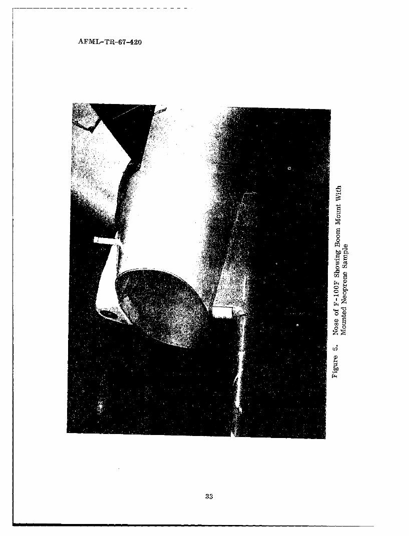
'5. Nose of F-100F Showing Boom Mount WithMounted Neoprene Sample 33
5. Goodrich Boot Sample Number 5 Installed onthe Noseboom Mount 34
Deicing Boot Samples on Wing Inboard Leading EdgeSections of F-100F Aircraft; Two Slits Placed inEach Boot for Tests 34
8. Goodrich Boot Samples 1 and 2 on Leading Edgeof Left Wing of F-100F Aircraft 35
•. Goodrich Boot Samples 3 and 4 on Leading Edgeof Right Wing of F-100F Aircraft 35
10. Nine Erosion Resistant Samples on Left HorizontalStabilizer of F-100F Aircraft 36
!. Two Erosion Resistant Samples on Vertical'tabilizer of F-100F Aircraft 36
1.2. Nine Erosion Resistant Samples on Right HorizontalStabilizer of F-100F Aircraft 37
1.3. Results of Hail Impact on the Specification NeopreneSample on Upper Surface of Right Horizontal Stabilizer 37
14. Hiail Impact Damage to Specification Neoprene onLower Surface of Right Stabilizer 38
- . -pecification Neoprene on Inboard Section of Left8%,-'.bilizer After Flight 7 38
i n Sp-cification Neoprene Sample on Lower Surface ofLeft Stabilizer After Hail Encounter During Flight 7 39
17. Erosion of Specification Neoprene on Right StabilizerAfter Flight 13 39
vi
AFML-TR-67-240
ILLUSTRATIONS (CONT)
FIGURE PAGE
18. Condition of Specification Neoprene Sample onLower Surface of Right Stabilizer After Flight 13 40
19. Condition of Specification Neoprene on Upper Surfaceof Right Stabilizer After Flight 16 40
20. Condition of Specification Neoprene on Lower Surfaceof Right Stabilizer After Flight 16 41
21. The Clear Urethane Sample on Leading Edge Showsan Approximate One-Inch Peel at End of Flights; theAdjacent Pigmented Urethane on Stabilizer Shows NoAdverse Effects at the End of Program 41
22. The Clear Urethane on Right Stabilizer Had No VisibleAdverse Effects and the Pigmented Urethane Inboard ofClear Urethane Had Approximately One-fourth of the ShoePeeled at the End of Testing 42
23. Peeled Segment of Pigmented Urethane on Right StabilizerAfter Last Thunderstorm Flight 42
24. Final Condition of Pigmented Urethane Sample on LowerSurface of Right Stabilizer 43
25. Peeling of Clear Urethane on Right Stabilizer Indicatedby Arrow Was Attributed to Overlapping of the Nickel Sample 43
26. Sections of Clear Urethane Tape (1) Were Torn FromSample on Right Stabilizer During Hail Encounter onFlight 7 and Clear Urethane (2) Was Peeled an AdditionalAmount on the Inboard Edge 44
27. Close-up of Damage to Clear Urethane on LowerSurface of Right Stabilizer After Flight 7 44
28. After Flight 16 the Clear Urethane on RightStabilizer was Being Peeled Intact With NoVisible Erosion of the Surface 45
29. Clear Urethane on Lower Surface of Right StabilizerWas Also Peeling Intact With No Wear on the Surfaceof the Material 45
30. Pigmented Urethane and Clear Urethane on LeftStabilizer Completed the Tests With No Adverse Effects 46
vii

AFML-TR-67-420
ILLUSTRATIONS (CONT)
FIGURE PAGE
31. First Sign of Breakdown of Nickel Sampleon Leading Edge of Vertical Stabilizer After Flight 7 46
32. Increased Damage to Nickel Sample on VerticalStabilizer as of Flight 16 47
33. Approximately Two-thirds of the Nickel Sampleon the Right Side of the Vertical Stabilizer WasLost by the End of Program; the Urethane SampleAbove the Nickel Had Little Damage 47
34. Damage to Nickel Sample on Right Stabilizer UponCompleting Tests 48
35. All Urethane Tape on Upper Surface of Left StabilizerWas Lost During Flight 7 48
36. Urethane Tape Left on Lower Surface of LeftStabilizer After Flight 7 49
37. Urethane Tape Remaining on Lower Surface ofRight Stabilizer After Hail Encounter During Flight 7 49
38. Estane on Inboard Edge of Upper Surface on LeftStabilizer Peeled as a Result of Hail Encounter on Flight 7 50
39. Estane on Lower Surface of Left Stabilizer ReceivedSlight Damage During Flight 7 50
40. Additional Peeling of Estane on Upper Surface ofLeft Stabilizer After Flight 13 51
41. Damage to Estane on Lower Surface of LeftStabilizer After Flight 13 51
42. Estane Boot Almost Completely Peeled FromLeft Stabilizer and Adjacent Neoprene WithInsignificant Amount Remaining on Leading Edgeon Flight 16 52
43. Damage to Estane and Neoprene on Lower Surface ofLeft Stabilizer on Flight 16 52
44. Slightly Peeled Section of Estane on Upper Surfaceof Right Stabilizer 53
45. Corner of Estane Pulled Slightly From LowerSurface of Right Stabilizer 53
viii

AFML-TR-67-420
ILLUSTRATIONS (CONT)
FIGURE PAGE
46. Neoprene on Upper Surface of Right Stabilizer ErodedAway During Flight 7 While Adjacent Estane ReceivedNo Damage 54
47. Neoprene on Lower Surface of Right StabilizerEroded From Aircraft on Flight 7 54
48. One Arrow Points to One of the Cuts inthe Leading Edge of Neoprene on Left Stabilizerand the Second Arrow Indicates the Damage to theHycar Boot During Flight 7 55
49. Damage to Neoprene and Hycar Boots on LowerSide of Left Stabilizer After Flight 7 55
50. Increased Deterioration of Neoprene and HycarBoots on Left Stabilizer Observed By Flight 13 56
51. Damage to Neoprene and Hycar Boots on LowerSurface of Left Stabilizer After Flight 13 56
52. Peeling of Hycar Boot on Right StabilizerDuring Flight 3 57
53. Hail Encounter on Flight 7 Removed Almost Allthe Hycar Boot From Upper Surface of Right Stabilizer 57
54. Severely Damaged Hycar Boot on Lower Surface ofRight Stabilizer After Seventh ThunderstormPenetration Mission 58
55. Three-fourths of Hycar Boot Removed FromUpper Surface of Left Stabilizer During Flight 16 58
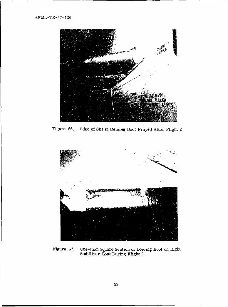
56. Edge of Slit in Deicing Boot Frayed After Flight 2 59
57. One-Inch Square Section of Deicing Boot on Right
Stabilizer Lost During Flight 2 59
58. Deicing Boot on Left Wing Root With Ruptured Section 60
59. Increased Failure of Deicing Boot on Left Wing AfterFlight 3 60
60. Severe Damage to Deicing Boot Caused by Hail andIce Crystal Impingement During Flight 7 61
ix

AFML-TR-67-420
ILLUSTRATIONS (CONT)
FIGURE PAGE
61. Significant Damage to Deicing Boot on Left WingCaused by Hail and Ice Crystal Encounter on Flight 7 61
62. Severe Breakdown of Deicing Boot on Right WingObserved After Flight 13 62
63. Increased Visible Erosion of Left Wing Deicing BootAfter Flight 13 62
64. Complete Breakdown of Deicing Boot on Left WingAfter Flight 16 63
65. Section of Deicing Boot on Lower Surface of LeftWing Received Little Damage on Flight 16 63
66. Surface of Deicing Boot oa Upper Leading Edgeof Wing Severely Damaged During Flight 16 64
67. Surface of Deicing Boot on Lower Surface of RightWing Leading Edge Not Damaged as Much as theSection on Top of Wing 64
68. Goodrich Samples 1 and 2 on Left Wing Tip Show LittleAdverse Effect After Flight 16; the Arrow IndicatesSlight Damage to Inboard Edge of Sample 1 65
69. Final Damage Received by Goodrich Samples onLeft Wing Tip 65
70. Goodrich Samples 3 and 4 on Leading Edge ofRight Wing Received Damage During Flight 7;the Arrow Points to a Cut on Leading Edge in Sample 3 66
71. Inboard Sample on Right Wing Tip With TornLeading Edge After Flight 13 66
72. Samples 3 and 4 on Right Wing Tip After Flight 16 67
73. Leading Edge of Inboard Sample on Right WingTip Removed 31 May; Leading Edge of OutboardSample Peeled From Half of Shoe 67
74. Damage to Goodrich Sample on Noseboom MountDuring Three Flights 68
x

AFML-TR-67-420
TABLES
TABLE PAGE
I Experimental Coatings 6
II Summary of Coating Applications 8
III Summary of Thunderstorm Penetrations 10
IV Summary of Erosion Damage after Flight Exposures 11-15
V Comparison of Whirling Arm Erosion andFlight Test Erosion 23
xi

AFML-TR-67-420
SECTION I
INTRODUCTION
Characterization of materials for rain erosion resistance is conventionallyaccomplished subsonically with a whirling arm simulation apparatus. In this
device, material specimens are fastened to the tips of a propeller-like blade
rotated at varying velocities (typically 500 mph) and water is impinged on the
specimens from a spray apparatus which simulates either a controlled drop size
distribution or a specific drop size. Rankings of materials for rain erosion
resistance based on whirling arm devices have been found to be similar for
different devices although the time to erode specimens varies because of
differences in the intensity of various simulated environments.
Correlation of erosion results obtained on the whirling arm formerly located
at the Cornell Aeronautical Laboratories with actual flight exposures was
accomplished in 1949 based on flights of an F-80 aircraft in rain (Reference 1).
The erosion resistance of numerous materials was assessed recently onthe Air Force Materials Laboratory (AFML) 500 -mphwhirling arm (Reference 2).
However, correlation of the AFML whirling arm exposure with flight experience
was needed to guide the research for improved materials. This report discusses
the flight experiences in an F-100F and compares the flight tests with the whirling
arm tests.

AFML-TR-67-420
SECTION II
SUMMARY
In a series of flight tests, conducted as part of Project Rough Rider, the
rain erosion resistance of experimental coatings after actual exposure on leading
edges in flights through thunderstorms was correlated with exposure results
obtained on a laboratory whirling arm water spray rain erosion simulation
apparatus. These flight tests were a cooperative effort conducted by the Adverse
Weather Branch, Deputy for Flight Test, Aeronautical Systems Division, and the
Elastomers and Coatings Branch, Nonmetallic Materials Division, Air Force
Materials Laboratory.
In the Project Rough Rider flight test program, sponsored by the Weather
Bureau and conducted by the Adverse Weather Branch, an F-100F aircraft flew
into thunderstorms around Tinker AFB, Oklahoma, to gather information for
identification, prediction, and the possible prevention of severe storms. Twenty-
seven patches of 15 experimental coatings were applied to the leading edges of
the wing tips, horizontal stabilizers, vertical stabilizer, and the noseboom.
Materials selected for this correlation included electroplated nickel, advanced
polyurethanes (brush applied), specification neoprene (MIL-C-7439B), clear
polyurethane tape, and adhesively bonded, preformed neoprene, urethane, and
nitrile rubber boots.
After 163 penetrations at 300 mph for 440 minutes in storms with varying
degrees of rain and hail intensity, the electroplated nickel coating and the brush-
applied clear polyurethane, and pigmented polyurethane coatings were in good
to excellent condition, but the specification neoprene coating, the urethane tape,
and all three types of performed rubber boots either were completely eroded
away or had suffered severe adhesion failures.
The materials in the flight tests were ranked in the same order as in the
laboratory test results obtained on a 6-foot diameter whirling arm apparatus
capable of velocities to 500 mph and rainfall simulation of 2 inches per hour.The erosion resistance of numerous materials has been characterized using
2

AFML-TR-67-420
this laboratory equipment, and the Rough Rider flight series enabled comparison
of the laboratory results with actual flight experience.
Although the thunderstorms were not well defined as to exact rainfall
conditions, the ranking of materials and types of erosion and adhesion failures
correlated very well between the flight tests and the whirling arm evaluations.
This confirms previous flight test correlations conducted during and after
World War II, as well as very recent helicopter rain erosion flight tests on
rotor blades.
The conclusion is that the laboratory rotating arm, water spray test apparatus
does correlate with actual flight tests through rain. This investigation also
confirms the applicability and superiority of the electroplated nickel and the
polyurethane coatings to protect aircraft leading edges and radomes, engine
compressor blades, and helicopter rotor blades from the effects of rain erosion.
3

AFML-TR-67-420
SECTION III
WHIRLING ARM APPARATUS
Subsonic rain erosion evaluations were conducted by the Air Force Materials
Laboratory on a whirling arm apparatus located in Building 20A at Wright-
Patterson Air Force Base, Ohio. This equipment included a 6-foot diameter
propeller blade made of tempered boiler plate mounted vertically on a 100-
horsepower electric motor, and at 2400 rpm was capable of attaining speeds of
500 mph at the blade tip where the specimens were inserted.
The speed of the equipment was regulated by a resistor bank from which
rigid control was possible. A revolution counter was utilized for monitoring
velocity, and vibration pickups were used for gauging specimen balance and
smooth operation. The whirling specimens could be observed using a mirror
and periscope arrangement and a stroboscopic unit synchronized with the blade
revolutions. This system enabled the observer to note the exact moment of
coating failure; i.e., penetration to the substrate or loss of adhesion. See Figures
1 and 2 for a pictorial presentation of the equipment.
Figure 2 shows the water system used to simulate the rain environment.
The 6-foot diameter, 2-inch pipe ring was equipped with twelve equally spaced
hypodermic needles to yield a rainfall simulation of from 2 to 24 inches per
hour. The hypodermic needles were No. 18 gauge (1.245 mm ID) which produces
rain droplets of 1.5- to 2.0-mm diameter as determined photographically. The
water system operated with 35 psig in the spray ring; this pressure enabled a
stream of water drops to impinge on the material specimens without distorting
the drops.
The specimen configurations were conformal specimens of aluminum or
various laminated materials (Figure 3). The conformal specimens were employed
extensively because they were easy to coat and their low drag and light weight
enabled efficient operation of the apparatus.
4
AFML-TR-67-420
SECTION IV
DESCRIPTION OF COATING APPLICATIONS
Coatings selected for the whirling arm-flight test correlation were chosenon the basis of a wide range of erosion resistance determined by whirling arm
evaluations. The materials selected for the flight tests were as follows:
Military specification neoprene (MIL-C-7439B)
Clear polyurethane (2 types)Pigmented polyurethane (white)
Electroplated sulfamate nickel
Polyurethane boot
Neoprene boot
Nitrile rubber boot
Polyurethane sheet
Polyurethane tape
Through an agreement between the Adverse Weather Branch and the B. F.
Goodrich Company, four additional materials and two deicing boots were applied
to the aircraft. These preformed boots included Nordel ethylene-propylene
rubber, neoprene with gum rubber backing, neoprene with Nordel backing,
and a white neoprene. The materials and their suppliers are listed in Table I.
The electroplated nickel and the P. 0. 655 urethane were applied by AFML.The other coatings were applied by the representatives of the various suppliers.
The coatings were applied in 12-inch wide strips around the leading edges of
the horizontal and vertical stabilizers, wing tips, and the nose boom mount.
The positioning of these samples is shown in Figure 4. A normalizing of the
sample position was attempted on the left and right stabilizers by reversing
the inboard to outboard order of the coatings "patches."
The specification neoprene, the two clear polyurethanes, and the white
polyurethane were applied by brushing the coatings over primers which had
been applied to the cleaned stainless steel substrate. The electroformed nickel
coatings on horizontal and vertical stabilizers and the polyurethane sheet on
the vertical stabilizer were applied using a two-part epoxy adhesive. The
5

AFML-TR-67-420
TABLE I
EXPERIMENTAL COATINGS
Coating Supplier
Black neoprene (MIL-C-7439B) Goodyear Tire and Rubber
Vithane CX-1046 clear polyurethane Goodyear Tire and Rubber
MS-61 clear polyurethane Olin Mathieson Chemical Corp.
MS-61P white polyurethane Olin Mathieson Chemical Corp.
Electroformed sulfamate nickel AFML
Yellow estane polyurethane boot B. F. Goodrich Company
Black neoprene 305 RN 32 boot B. F. Goodrich Company
Hycar nitrile rubber boot B. F. Goodrich Company
Polyurethane P. 0. 655 sheet Armstrong Cork Company
Y-9265 transparent polyurethanetape 3-M Company
Nordel 37RM185 ethylene-propylenerubber boot B. F. Goodrich Company
305RN32 neoprene with gum rubberbacking boot B. F. Goodrich Company
305RN32 neoprene with Nordel
backing boot B. F. Goodrich Company
White neoprene 121DJ33 boot B. F. Goodrich Company
Deicing boots (25S and 26S) B. F. Goodrich Company
6

AFML-TR-67-420
transparent polyurethane tape was applied with its own self-backed acrylic
adhesive. The preformed polyurethane, neoprene, nitrile rubber, and the other
boots were applied over a primed surface (in many cases) using epoxy- and
neoprene-based adhesives specially provided for these materials. The coating
application procedures are summarized in Table II.
The coating thickness was standardized at 0.015 inch which was taken as
a maximum practical thickness considering application techniques, radar trans-
mission requirements when used on a radome, and number of coats required to
obtain a sufficient thickness. All boot materials except the black neoprene
ranged from 0.017 inch to 0.037 inch. The preformed boots are difficult to
fabricate in thin coatings and thin spots often result; furthermore, the use of
cloth backing plus adhesive also requires thicker coatings (Table II). The coatings
after application are shown in Figures 5 through 12.
7

AFML-TR-67-420
N N N N ~bD N N N
.0 o0 w00. 0 0 ~ ~~~, 0 0 -
b2 tO 02 0 o t to bo b 0o
0d C d c d ' d b 0ý4~~~I 4 4 44k4I t
') '0 t0~' 0 ' 0 ' - .
>
0
W 0o w -0 's - -
0 0 3. )a. 0 0 200 0 20 2'~0 A o'004 g 0 -d -0 $4 .00 .00 00 .00 ý .~0 0 .00 0
zo 0- 0-
*..0
I-D z 0 p
0'$4P400 0
F4 0 r.0r2t . 0) 0) 0 0 a ) C0 0)01
>~ ~ 02 0 2'- 13 $4 $4 F . 0 F . .. . 0
o~~ ~ ~~~ 0 'D~~~ ~~ ~ ~ 0 ~ 0 ':t 0 0 0 ~ o 0 0 o
0 ~ ~ ~ D C) ~0 0 ,< 0 0~
0 0 0= -4 'a r0
ý~~~> 4 w 1 , ,C
0 04 mQ 0 0I 0d 0 , p ,p q p
0-.. 0 L4n LO~ 1O LO 40 to * CI .. ~ 4 o * 0
c,0 0 ) 0 0 0 0 0 0 I I I 0 0 I 0
0 0 0 0
0d 0 0 04
0d bl Z
q0 2t 0 z
$-4 Cd 0 p
0 d (1 zz 0Z0 (W 4 g0 2 42
E-4 0 0 k .C4d 0 C4 m
'00 ; 0 0 to '00-
01 04 $
k 04d w -4 0 k' 0 0 *D
_~~ 0P 0 ,- c Cd 4-
0) 0d 0d o 0 p- 0 04
8

AFML-TR-67-420
SECTION V
EROSION RESULTS ON FLIGHT EXPOSURES
1. DATA COLLECTION
Samples were exposed to as much thunderstorm environment as feasible
from 19 April to 30 May1967. This exposure was accomplished over an area with
a radius of 100 -nautical miles about the National Severe Storms Laboratory (NSSL)
and radar site, Norman, Oklahoma. The relative severity of the thunderstorm
system was determined by the NSSL radar which was also utilized to vector the
F-100F aircraft through the thunderstorm. Each traverse was flown at an initial
indicated airspeed of 275 knots (317 mph). The altitude depended primarily on
the height of the storm system and therefore ranged from 10,000 to 35,000 feet
pressure altitude.
The pilot's comments were taped during each traverse to tell when hail,
slush, and/or liquid water were encountered and the severity of the encounter.
An ice detector system provided information on ice crystal encounter, and other
test gear was utilized to determine the magnitude of the vertical wind gusts,
The samples of materials were examined after eachflight for surface wear,
breaks, or peeling. No corrective action was taken to alleviate these forms of
breakdown when they occurred. Photographs were taken of all significant
deterioration.
The test samples were subjected to natural erosion conditions which included
hail, ice crystal, and/or liquid water impingement for 439 minutes and 40 seconds
(Table III). Transcriptions of the pilot's taped comments and the recorded ice
detector data told when these products of the thunderstorm were encountered.
2. EROSION RESULTS
Table IV summarizes the erosion results after flight exposure on each
material. Reference 3 is an evaluation of erosion materials in severe storms.
The individual discussions of progressive erosion and/or failure for individual
coatings are in the following paragraphs.
9

AFML-TR-67-420
0C C ) r C' l m~ U - C .-4f m' 04 eq mC C) 0 .-4 -,I m m
;4-
r- 4 4 -4 .I-q ,-I r-4 1-4 c-4 0l 04 m- - 4 ~ 4 .
z0
0 to m) m) m m U) to m) U 0 0 0D to to U) to 0> 0> to to 0
w' CC 0 00 - C 4 C) ~ C .4 C .j C C 4 0 C
mC CD C)1 0- 00) U)) t- 00 v- C'O VC OD 14 Cto VC OD c)C
o 1 -1 .- I .- I C') c) "' C') C) C' co) Cl) C'M~
U) 0 U) 0 0 0 0D 0) 0 0> to 0D 0 to 0D 0 0> LO 0D to 0 LOc~Cd r. 4 ,4 C' U)1 m tt CID m' Vj C') C') ,.-I
o -44
4 d C')m C') in 00 t- U) v ,-I U) m 0> V C') in) 0 C ID' 0 C' C) CCo I C11 C') r- ,-4 ,-i C'1 C") C) r-I .-l ,4 C' 1-4 m' C) C') C') -1 C'
bfl
.0
a) U) CD 0 , 0 CC U) - t- t- CD co) C'- r1 C' to C') C') 0. CD
'aj
~ F~if i ifif i if f i10I

AFMLý-TR-67-420
TABLE IV
SUMMARY OF EROSION DAMAGE AFTER FLIGHT EXPOSURES
CumulativeTime in Storms
Material Flight No. (Minutes) Damage Description
RIGHT STABILIZER
Neoprene 7 137:15 Hail damage, bare metal(MIL-C-7439B) exposed on leading edge.
13 214:10 3/4 of leading edgeexposed.
16 276:25 Entire L. E. and topsurface gone.
Clear urethane 22 439:40 Sample entirely intact andglossy.
White urethane 20 391:55 No erosion evident at anyMS-61P time.
21 and 22 439:40 4" peeling of white becauseof adhesion loss of clearsample next to it.
Clear urethane 3 61:55 No erosion evident at anyMS-61 time.
16 276:25 Peeling began.
20 391:55 Half of shoe peeled andremoved. Remaining half
lost in flight.
Y-9265 urethane 7 137:15 Damaged after flight.tape
8 137:15 Entire tape patch gone.
Estane boot 16 276:25 Slight peeling of inboardedge.
22 439:40 Peeled 1" from inboard.No surface roughness orbreaks.
11

AFML-TR-67-420
TABLE IV (CONT)
CumulativeTime in Storms
Material Flight No. (Minutes) Damage Description
RIGHT STABILIZER (Continued)
Neoprene boot 7 137:15 Almost entire sampleremoved by hail impact.
Hycar boot 2 36:55 Peeling noted.
3 61:55 Peeling advanced.
7 137:15 Sample almost completelyremoved.
9 158:15 Remainder removed.
Electroplated 16 276:25 No erosion.nickel
17-22 439:40 Breakdown of bond,continued shearing awayof nickel.
LEFT STABILIZER
Hycar boot 7 137:15 1/3 of inboard section gone.
10 184:10 1/2 of inboard section gone.
13 214:10 3/4 of inboard section gone.
17 314:55 Remainder lost.
Neoprene boot 7 137:15 Cuts along length of
specimen.
13 214:10 Small cuts enlarged.
16 314:55 Entire leading edgedestroyed.
12

AFML-TR-67-420
TABLE IV (CONT)
CumulativeTime in Storms
Material Flight No. (Minutes) Damage Description
LEFT STABILIZER (Continued)
Estane boot 7 137:15 Peeling of inboard edge.
13 214:10 1/3 of shoe sheared away.
17 314:55 Shoe completely lost.
Y-9265 urethane 6 113:15 Inboard end peeledtape back 1/4".
7 137:15 Entire tape patch gone.
Electroplated 22 439:40 No erosion. Completelynickel intact.
Clear urethane 22 439:40 Sample entirely intact andMS-61 glossy.
White urethane 22 439:40 Sample entirely intact andMS-61P glossy.
Clear urethane 7 137:15 Excellent condition, peelingCX-1046 1/4" from inboard end.
22 439:40 Excellent condition, peeling1/4" from inboard end.
Neoprene 7 137:15 1/3 of leading edge re-(MIL-C-7439B) moved. (Observations
terminated.)
VERTICAL STABILIZER
P.O. 655 urethane 18 338:10 Peeling.sheet
22 439:40 Peeled segment torn off.Otherwise OK.
13

AFML-TR-67-420
TABLE IV (CONT)
CumulativeTime in Storms
Material Flight No. (Minutes) Damage Description
VERTICAL STABILIZER (Continued)
Electroplated 7 137:15 First indication of peeling.nickel
16 276:25 Half of right side of samplegone.
22 439:40 2/3 of metal layer gone,rest separated from base.
RIGHT WING
Deicing boot 2 36:55 Edges of slits noticeablyfrayed.
3 61:55 Boot torn, piece missingfrom outboard edge.
16 276:25 Removed by ProjectEngineer.
Nordel 5 98:15 Peeling inboard.
16 276:25 Peeling 1", loss ofadhesion.
22 439:40 Little noticeable erosionof Nordel itself.
Neoprene with 7 137:15 Cut along leading edge.gum rubberbacking 10 184:10 Adhesion loss along
leading edge.
13 214:10 Leading edge eroded. Halfof sample on leading edgegone.
14
AFML-TR-67-420
TABLE IV (CONT)
CumulativeTime in Storms
Material Flight No. (Minutes) Damage Description
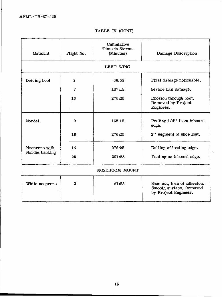
LEFT WING
Deicing boot 2 36:55 First damage noticeable.
7 137:15 Severe hail damage.
16 276:25 Erosion through boot.Removed by ProjectEngineer.
Nordel 9 158:15 Peeling 1/4" from inboardedge.
16 276:25 2" segment of shoe lost.
Neoprene with 16 276:25 Dulling of leading edge.Nordel backing
20 391:55 Peeling on inboard edge.
NOSEBOOM MOUNT
White neoprene 3 61:55 Shoe cut, loss of adhesion.Smooth surface. Removedby Project Engineer.
15

AFML-TR-67-420
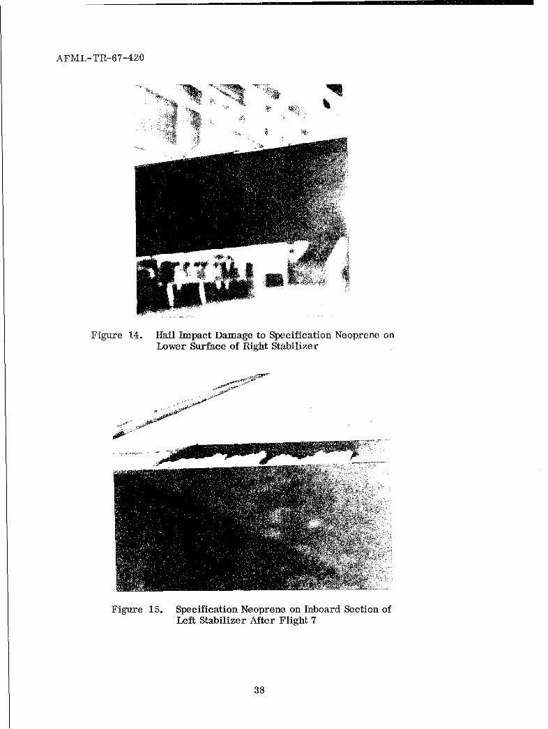
a. Specification Black Neoprene (MIL-C-7439B) (Position B)*
The first visible damage received by this coating was noted after Flight 7.
Hail approximately the size of marbles was encountered on at least two penetra-
tions. Figures 13 and 14 show that one-third of the leading edge of the sample was
removed from the top and bottom of the right stabilizer. The neoprene on the
left stabilizer received similar damage on this flight as can be seen in Figures
15 and 16. Only bare metal remained at the exposed sections. Both coatings had
been torn from the stabilizer in small segments based on the jaggedness of the
edge of the remaining samples. The sample on the left stabilizer was considered
to have failed on Flight 7; however, the test continued with the sample on the
right stabilizer. The postflight inspection for Flight 13 showed that three-fourths
of the leading edge of the right stabilizer initially covered by neoprene was
now exposed (Figures 17 and 18). The neoprene adhered to the bottom of the
stabilizer but gradually peeled from the top of the stabilizer during Flights 12
through 16. Testing was terminated on this sample after Flight 16 because the
entire leading edge and most of the top surface had eroded away (Figures 19 and
20).
b. Clear Urethane (Position C)
The urethane sample on the left stabilizer peeled 0.25 inch during Flight 7.
It is believed the adhesive bond between this segment of urethane and the metal
was weakened by the erosion of the adjacent neoprene. Peeling continued at an
insignificant pace until termination of the flight phase at which time the sample
had been peeled approximately one inch along the leading edge (Figure 21).
The rest of the sample was glossy and had no surface roughness, cuts, or peeled
sections. The urethane on the right stabilizer was also glossy and had no surface
roughness, cuts, or peeled sections on the entire shoe after Flight 22 (Figure 22).
c. Pigmented Urethane (Position D)
The pigmented urethane on the right stabilizer withstood the adverse con-
ditions until its bond to the metal was broken when the inboard, adjacent urethane
sample was blown from the aircraft during Flight20. The sample peeled 4 inches
during the next two flights. Figures 23 and 24 show the condition of this sample
* Position letters refer to Figure 4
16

AFML-TR-67-420
after Flight 22. The section which remained had a glossy, smooth surface and
no cuts or peeled edges. The pigmented urethane on the left stabilizer was
completely intact and glossy upon completion of the last flight (Figure 21).
d. Clear Urethane (Position E)
The sample on the right stabilizer began peeling during Flight 3 (Figure 25).
This sample overlapped the electroformed nickel on the inboard side of the
urethane. The peeling progression on Flight 7 is shown in Figures 26 and 27
(top and bottom of right stabilizer, respectively). The peeling increased during
Flights 4 through 16 until half of the shoe was peeled from the stabilizer
(Figures 28 and 29). The segment that peeled was removed on 21 May and
forwarded to the Elastomers and Coatings Branch for examination. The remaining
half of the sample continued to peel and was lost during Flight 20. This sample
failed because the adhesive could not hold bond between the urethane and the
metal against the wind blast. The urethane on both stabilizers showed no visible
adverse effects or surface roughness. In addition, the urethane sample on the
left stabilizer remained on the aircraft until completion of the tests (Figure 30).
e. Electroformed Nickel (Position F)
This coating showed no sign of erosion or any degree of surface roughness
during the entire flight phase; however, two of the three samples did peel at a
relatively rapid rate after the bond between the nickel and the base was broken.
This peeling occurred on the top surface of the right stabilizer and on the right
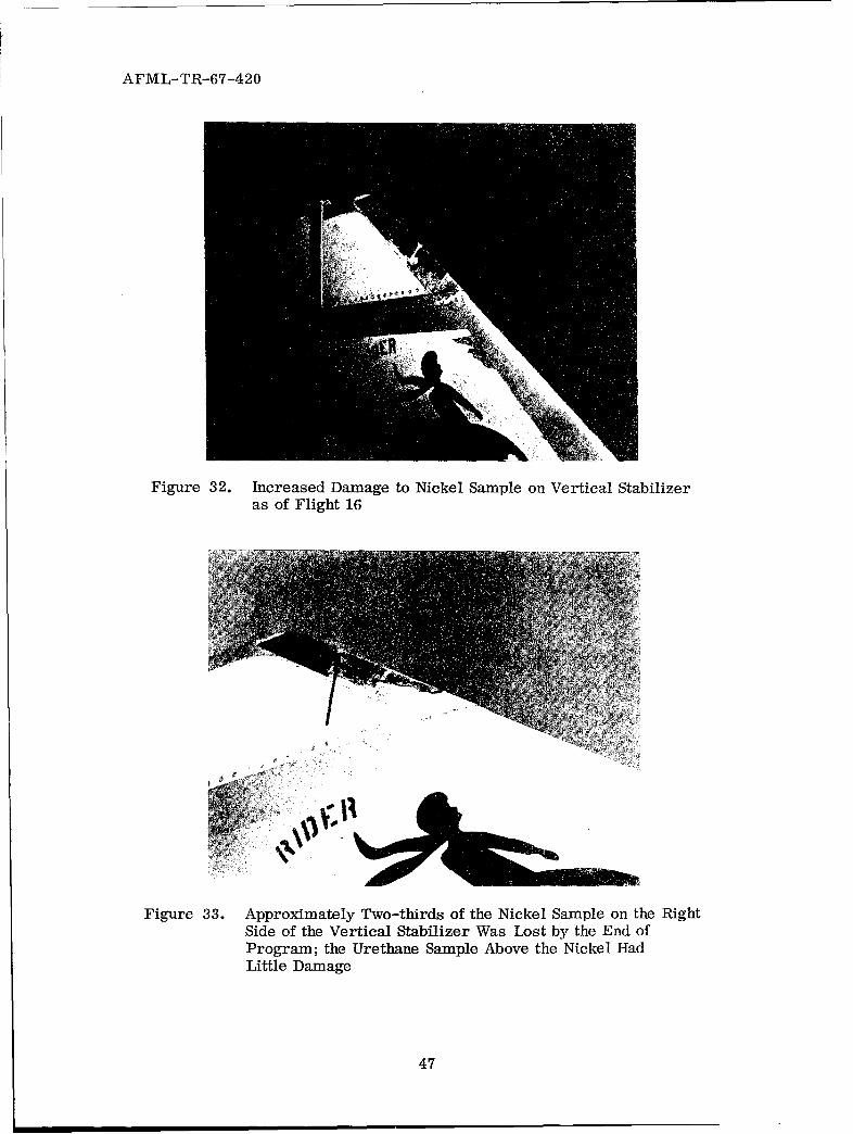
surface of the vertical stabilizer. The nickel on the vertical stabilizer gave the
first sign of peeling after Flight 7 (Figure 31). The peeling continued in each
flight until approximately one-half of the sample on the right side of the stabilizer
had disappeared after Flight 16 (Figure 32). Two-thirds of the metal layer was
removed and the remaining segment had separated from the base upon completion
of the last data flight on 30 May 1967 (Figure 33). Breakdown of the bond between
the nickel and base on the right stabilizer began during Flight 16. Post-flight
inspection showed a 1/32-inch gap between the metal and base. The shearing of the
metal occurred during Flight 17 and continued through Flight 22. The final piece
of metal had been sheared from the top surface of the stabilizer during Flight 22
(Figure 34). The nickel which was sheared from the aircraft was rolled into a
spiral and then was torn away in flight in both the aforementioned flights. The
surface to which the nickel had been electroformed did not erode from the aircraft.
17

AFML-TR-67-420
f. Y-9265 Urethane Tape (Position G)
The tape showed no visible adverse effects for the first five flights. Then,
on Flight 6, the inboard end of the tape on the left stabilizer was peeled back
approximately 0.25 inch. The test was completed with this tape on this stabilizer
after completion of Flight 7 (Figures 35 and 36), since the entire sample was
torn from the aircraft in flight. The tape on the right stabilizer was also damaged
as a result of Flight 7 (Figures 26 and 37). The adhesive which remained on both
stabilizers was sticky to the touch. The remaining tape on the right stabilizer
was lost during Flight 8. Failure of both samples was due primarily to the hail
encounter during Flight 7 and to the inability to the adhesive to withstand the
wind blast.
g. Estane Boot (Position H)
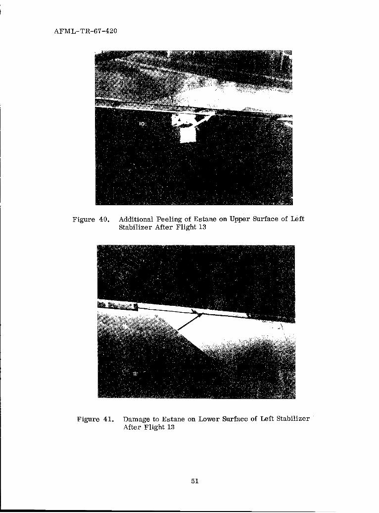
The first visible sign of damage was peeling of the inboard edge of the
sample on the left stabilizer which occurred during Flight 7 (Figures 38 and 39).
This partial breakdown continued through Flight 13 at which time approximately
one-third of the shoe had been sheared away (Figures 40 and 41). This loose
segment was not brittle nor did it have any surface roughness. (The shoe retained
these characteristics until complete removal occurred.) The failure of this
sample appears due to the inability of the adhesive to hold the shoe to the metal.
This was particularly noticeable during the Flight 16 postflight (Figures 42 and
43)_ The adhesive along the leading edge was adhering to the loosened section
of Estane, but no adhesive remained on the exposed metal surface. This shoe
was lost during flight 17. The Estane boot on the right stabilizer showed slight
peeling of the inboard edge as a result of Flight 16; however, the peel was too
insignificant to photograph. This sample remained glossy with no surface
roughness or breaks throughout the test phase except for the peeling of the
inboard edge which had increased about an inch on the top and bottom stabilizer
surfaces (Figures 44 and 45).
h. Neoprene Boot (Position J)
The neoprene boot on the right stabilizer showed no visible adverse effects
until Flight 7 when almost all the sample was lost during the flight (Figures 46
and 47). The boot on the left stabilizer remained intact although it had cuts along
the length of the boot (Figures 48 and 49). It can be speculated that the hail which
was encountered shredded the missing segment on the right stabilizer. The
18

AFML-TR-67-420
small cuts received were enlarged during the following flights as can be seen
in the Flight 13 postflight photograph of the sample (Figures 50 and 51). The
final damage was received and photographed after Flight 16 (Figures 42 and 43).
The test was considered to be over for this sample since the entire leading
edge had been destroyed.
i. Hycar Boot (Position K)
This sample began peeling on the right stabilizer during Flight 2; however,
the peel was considered too insignificant to photograph. The peel continued to
advance and was photographed after Flight 3 (Figure 52). No significant
advancement of peeling occurred until Flight 7 when this sample was almost
completely removed (Figures 53 and 54). It is not known if the failure was the
fault of the adhesive alone or if the shoe simply came apart under the conditions
to which it was subjected. The remaining segment of shoe over the leading edge
was lost during the nextflight. The Hycar boot on the left stabilizer lost one-third
of its inboard section during Flight 7 (Figures 48 and 49). One-half of the sample
was gone after Flight 10 and approximately three-quarters of the boot was lost
after completion of Flight 13 (Figures 50 and 51). Postflight inspection showed
one-fourth of the leading edge of the shoe to be left after Flight 16 (Figure 55).
This remaining segment disappeared sometime during Flight 17. The surface of
the material was glossy and had no surface roughness during the test period.
j. Deicing Boots (Position L)
The boot on the right wing had two slits perpendicular to the wing leading
edge which were intentionally put in the material by B. F. Goodrich personnel
prior to the tests. The outer edge of each slit was frayed noticeably after
Flight 2 (Figures 56 and 57) and the slit on the upper surface of the wing was
torn during Flight 3. This boot also had a one-inch square piece missing from
the outboard edge (arrow, Figure 57). The boot on the left wing had two slits
parallel to the wing leading edge which were also intentionally put in the boot
by B. F. Goodrich personnel prior to the test. The first sign of any adverse
effect was recorded after Flight 2. The air blast entered through both slits to
form a large "bubble" outboard of each slit. These bubbled areas were stressed
until, in one case, rupture occurred (Figure 58). The "bubble" area near the
w1ing root did not rupture until Flight 3 (Figure 59), when both boots received
severe damage from hail and ice crystals. Figures 60 and 61 show the entire
19

AFML-TR-67-420
leading edge of each boot to have numerous minute cuts exposing a pink-colored
layer under the black outer surface of the boots. The leading edges continued to
erode through Flight 13 (Figures 62 and 63) when the. main seam pattern was
clearly visible. It was obvious by Flight 16 that the boots would gradually fail
back to the main seams running parallel to the wing leading edge and to the
second set of main seams perpendicular to the leading edge (Figures 64 through
67). The boots were therefore removed after Flight 16.
k. P. 0. 655 Urethane (Position A)
This material remained in its initial condition as shown in Figure 11 until
Flight 18 when the leading edge began to peel. This peeled segment was torn
from the aircraft during Flight 22. The shoe had no surface roughness, breaks,
or other peeled sections. Figure 33 shows the condition at the end of the
program.
1. Nordel Ethylene-Propylene Rubber (Position M)
The shoe peeled about one-fourth inch on the inboard leading edge as a
result of Flight 9 and the leading edge was slightly duller than the rest of the
shoe. However, the first damage to the shoe appeared after Flight 16 when a
relatively small segment of the shoe was lost in flight (Figure 68). Tests were
terminated on 31 May after 22 flights. Figure 69 shows that the shoe had no
surface roughness or damage besides the 2-inch section that was lost from the
leading edge.
m. Neoprene with Nordel Backing (Position N)
The postflight inspection for Flight 16 of this shoe showed the leading edge
was dull relative to the top and bottom of the shoe (Figure 68). The wear of
the leading edge was not noticeable until this flight. The next and last photograph
was taken on 31 May after tests were completed. The shoe showed no adverse
effects other than slight peeling of the leading edge on the inboard side of the
shoe and the dullness of the leading edge (Figure 69). The peeling began during
Flight 20.
n. Neoprene with Gum Rubber Backing (Position 0)
This shoe received the first visible damage as a result of Flight 7 (Figure
70) when it was cut along the leading edge. Inspection after Flight 10 showed the
20

AFML-TR-67-420
bond with the metal aircraft skin had been loosened along the entire length of
the leading edge. The leading edge was visibly worn compared to the rest of the
shoe. The Flight 13 postflight inspection showed half of the leading edge of the
shoe to be gone and the remaining section to be well eroded (Figure 71). As
seen after Flight 16 (Figure 72), the leading edge failure continued to progress.
The final condition was photographed on 31 May (Figure 73). This sample
probably could have withstood the erosion for a longer period if the adhesive
had held the material to the metal leading edge.
o. Nordel Ethylene-Propylene Rubber (Position P)
This shoe began peeling on the inboard side during Flight 5. The shoe
peeled approximately an inch as a result of Flight 16 (Figure 72). Inspection
indicated the material was not held to the metallic leading edge by the adhesive.
The air blast was able to form an air pocket under the leading edge of the
sample and the pressure was great enough to slowly tear the leading edge
from this material (Figure 73). The rest of the material still had a smooth
surface with no cuts. Apparently this shoe too could have withstood the erosion
had the bond between the substance and the aircraft not been broken.
p. White Neoprene (Position Q)
This sample showed no adverse effects until Flight 3 (Figure 74) at which
time the material was removed because the air blast would have removed it
on the next flight. The shoe was cut and the adhesive had lost its grip of the
metal surface under at least three-quarters of the sample. The material still
had a smooth surface at the time of removal.
21
AFML-TR-67-420
SECTION VI
COMPARISON OF WHIRLING ARM AND FLIGHT EXPOSURES
The whirling arm exposures of the materials selected for these correlations
were made at the AFML standard conditions of 500 mph in two inches per hour
simulated rainfall. The time to failure (the time to penetrate the coating) is
used as the criterion for ranking materials as to erosion resistance. The
types of failures may be erosive (wearing away of the coating) or adhesive
(complete or partial loss of the coating-substrate bond).
The times to failure on the whirling arm for the ten experimental coatings
are shown in Table V. For comparison, the corresponding times of failure
from the flight tests are also shown in this table. The materials which were
applied by B. F. Goodrich to the wings and noseboom mount had not been
specifically tested on the whirling arm; however, two similar materials, the
neoprene boot with gum rubber backing and the white neoprene, had been
evaluated. This comparison can also be seen. The results in Table V are
for coatings of the same thickness (±2 mils) on either whirling arm or aircraft
for each compared.
As may be seen from Table V, materials such as the polyurethanes
(clear and pigmented) and the electroplated nickel which had performed well
in whirling arm evaluations were uneroded after the full exposure on the
aircraft. The partial adhesion loss on the nickel coating and one patch of the
polyurethane can be attributed to the lack of experience in bonding the nickel
to stainless steel and the overlapping of the polyurethane on the nickel which
gave an edge for the wind blast to work on.
Materials which had performed poorly or only moderately well on the
whirling arm such as the white neoprene, the neoprene boots, the urethane
tape, and the specification neoprene (MIL-C-7439B) were also badly eroded
after the thunderstorm exposure. In general, the modes of failure for the
various coatings were correlatable whether the water impingement was the
simulated environment of the whirling arm or the actual rain exposure of the
flight tests.
22

AFML-TR-67-420
TABLE V
COMPARISON OF WHIRLING ARM EROSIONAND FLIGHT TEST EROSION
Whirling Arm1 Type of Flight Test 2 Type ofTime to Failure Failure Time to Failure Failure
Material (seconds) (minutes)
Specification 318 Erosion 137:15 Erosionneoprene(MIL-C-7439B)
Clear urethane 474 Erosion and 439:403 LittleCX-1046 adhesion erosion
White urethane 1250 Erosion 439:403 No erosionMS-61P
Clear urethane 3774 Erosion 439:403 No erosion.MS-61 (391:55) Adhesion
failure onone patch
Electroplated 11,436 Erosion 439:403 No erosionnickel
Y-9265 urethane 667 Adhesion and 137:15 Adhesiontape erosion
Estane boot 924 Adhesion 214:10 Adhesion
Neoprene boot 117 Adhesion 137:15 Erosion andadhesion
Hycar boot Not run 137:15 Erosion andadhesion
P.O. 655 polyure- 450 Adhesion 338:10 Adhesionthane sheet
Neoprene boot with 78 Adhesion 184:10 Adhesiongum rubber backing
White neoprene 226 Erosion 61:55 Adhesion
1 Whirling arm exposure - 500 mph, 2 inches/hour rainfall intensity.
2 Flight test exposure - 300 mph, varying intensities of rain and hail.
3Full exposure on aircraft.
23

AFML-TR-67-420
SECTION VII
DISCUSSION
The whirling arm technique as a means of simulating rain erosion exposure
for the measurement of resistance of various materials has long been accepted as
an inexpensive, well-controlled method. Although placing material specimens on
the tip of a propeller-like blade and spinning them at velocities up to 500 mph
imposes centrifugal forces on the materials, the design of most whirling arms
(large radius of the blade) has minimized the centrifugaleffects. The conventional-
lyused rain environment of 1 to 2 inches per hour simulated rainfall is severe
when compared to the incidence of natural rain, but it has been shown to be
reproducible and effective in screening and developing erosion resistant
materials.
This comparison of the AFML whirling arm results with those of actual
flight exposure has further shown the whirling arm results to be correlatable
to flight experience. Despite the fact that the whirling arm evaluations were
accomplished at 500 mph and the F-100F penetrations were made at 300 mph,
the erosion of the various materials was similar on either exposure. The relative
ranking of materials - polyurethanes and electroplated nickel best and the
preformed boots, urethane tape, and specification neoprene worst - obtained on
the whirling arm was borne out in the flight performance.
The only exception was the CX-1046 clear polyurethane which exhibited
only fair resistance on the whirling arm but was relatively undamaged after
flight exposure. In this case, the primer used was much improved over that for
the whirling arm exposures.
The adhesion failures of the preformed boots are normal modes of failure for
these materials because the water drop impingement deforms the boot, transmits
the shear stress to the boot-adhesive bond, and breaks it. In some cases, the
boot is penetrated in one spot and the water subsequently loosens the boot
along its entire length. Examination of the patches on the aircraft showed
either type of failure may have occurred.
24

AFML-TR-67-420
The adhesion losses of the electroplated nickel were due to inadequate
bonding of this material to the stainless steel leading edges. The research
with this material has concentrated on protection of metal and laminate substrates
by directly applying the nickel (Reference 4). The epoxy adhesive used to apply
the preformed nickel sheath was a good one, but the impact of the rain and hail
was sufficient to break the bond. A directly plated nickel leading edge would
have shown no effects of the exposure.
The adhesive loss of the clear urethane tape is traceable to the weakness
inherent in the adhesive-to-tape bond because the adhesive on the metal leading
edge remained after all flights even though the tape was completely gone after
Flight 7. The adhesion loss of the clearpolyurethane MS-61 on the right stabilizer
can be attributed to its overlapping the nickel coating on one edge which gave
the rain and subsequently the airstream an edge from which to loosen its bond.
No erosion was evident on this sample.
The flight erosion results would have been more meaningful if aircraft-
borne cameras and instrumentation could have been used continuously to
monitor the progressive erosion of the coatings but limitations of the aircraft
prevented this. Similarly characterization of the actual rainfield encountered
would have assisted in the comparison. However, examination of the various
materials after the flights and comparison of their failures with whirling arm
results have demonstrated the whirling arm to be an effective means of simulating
rain erosion of aircraft materials.
25

AFML-TR-67-420
SECTION VIII
CONCLUSIONS
The whirling arm technique for simulating rain erosion has been correlated
with actual flights of an F-100F aircraft in thunderstorms and these conclusions
have been reached;
1. The rankings of the rain erosion resistance of materials as obtained
on a whirling arm have been borne out in actual flight exposures.
2. The outstanding performance of polyurethane and electroplated nickel
coatings in a simulated rain environment was confirmed in an actual exposure
to rain.
3. The whirling arm method is an effective research tool for guiding
exploratory development of rain erosion resistant materials.
26

AFML-TR-67-420
SECTION IX
FUTURE WORK
A whirling arm erosion simulator capable of variable velocities to Mach 1.2
is currently being developed by AFML. Materials identical to those evaluated
on the 1967 Project Rough Rider will be exposed on this equipment for comparison
of the results and calibration of the rig.
Future flight tests in rainstorms will be utilized whenever possible to
further aid in the development of improved rain erosion resistant materials
and refinement of simulation techniques.
27

AFML-TR-67-420
REFERENCES
1. W. B. Trapp, Erosion of Leading Edges of F-80 Airplane, MCREXA-45124-18, E. 0. 451-362, November 1949.
2. G. F. Schmitt, Jr., Research for Improved Subsonic and Supersonic RainErosion Resistant Materials, AFML-TR-67-211, Air Force MaterialsLaboratory, Wright-Patterson Air Force Base, Ohio. January 1968.
3. Captain Edward Miller, Evaluation of Erosion Materials in Severe Storms,ASTDN-FTR-67-13, Aeronautical Systems Division, Wright-PattersonAFB, Ohio, August 1967.
4. J. H. Weaver, Nickel Electroplated Nonconductive Materials for RainErosion Protection, AFML-TR-66-398, Air Force Materials Laboratory,Wright-Patterson Air Force Base, Ohio, May 1967.
28

AFML-TR-67-420
Figure 1. AFML 500-MPH, 6-Foot Diameter Whirling Arm
29

AFML-TR-67-420
11,17
"41
Figure 2. AFML Whirling Arm Showing Blade With SpecimenInstalled, Pipe Ring, and Periscope Tube
30

AFML-TR-67-420
- .005I"2"455~+'.000 i -/
2.435+008
1.20+00
NACA .0025 AIRFOIL- 4- INCH CHORD
DISTANCE FROM LEADING EDGE
% CHORD ORDINATE ABSCISSA(Y) (X)
0.00 0.00 0.000
1.25 0.05 0.158
2.50 0.10 0.2185.00 0.20 0.296
7.50 0.30 0.350
10.00 0.40 0.390
15.00 0.60 0.446
20.00 0.80 0.478
25.00 1.00 0.485
30.00 I .20 0.500
OUTER DIMENSIONS
OF 1/8-INCH SPECIMEN
DIMENSIONS IN INCHES
MATERIAL - 2024 -T4 ALUMINUM
Figure 3. Whirling Arm Rain Erosion Test Specimen
31

AFML-TR-67-420
, w
0
0bGi
C4rx4
oII
C>
4
32
AFML-TR-67-.420
0
33

AFML-TR-67-420
Figure 6. Goodrich Boot Sample Number 5 Installed onthe Noseboom Mount
Figure 7. Deicing Boot Samples on Wing Inboard Leading EdgeSections of F-100F Aircraft; Two Slits Placed inEach Boot for Tests
34

AFML-TR-67-420
Figure 8. Goodrich Boot Samples 1 and 2 on Leading Edgeof Left Wing of F-100F Aircraft
Figure 9. Goodrich Boot Samples 3 and 4 on Leading Edgeof Right Wing of F-100F Aircraft
35

AFML-TR-67-420
S-r
Figure 10. Nine Erosion Resistant Samples on Left HorizontalStabilizer of F-100F Aircraft
Figure 11. Two Erosion Resistant Samples on VerticalStabilizer of F-100F Aircraft
36

AFML-TR-67-420
Figure 12. Nine Erosion Resistant Samples on Right HorizontalStabilizer of F-100F Aircraft
Figure 13. Results of Hail Impact on the Specification NeopreneSample on Upper Surface of Right Horizontal Stabilizer
37
AFML-TR-67-420
Figure 14. Hail Impact Damage to Specification Neoprene onLower Surface of Right Stabilizer
Figure 15. Specification Neoprene on Inboard Section ofLeft Stabilizer After Flight 7
38

AFML-TR-67-420
Figure 16. Specification Neoprene Sample on Lower Surface ofLeft Stabilizer After Hail Encounter During Flight 7
Figure 17. Erosion of Specification Neoprene on Right StabilizerAfter Flight 13
39
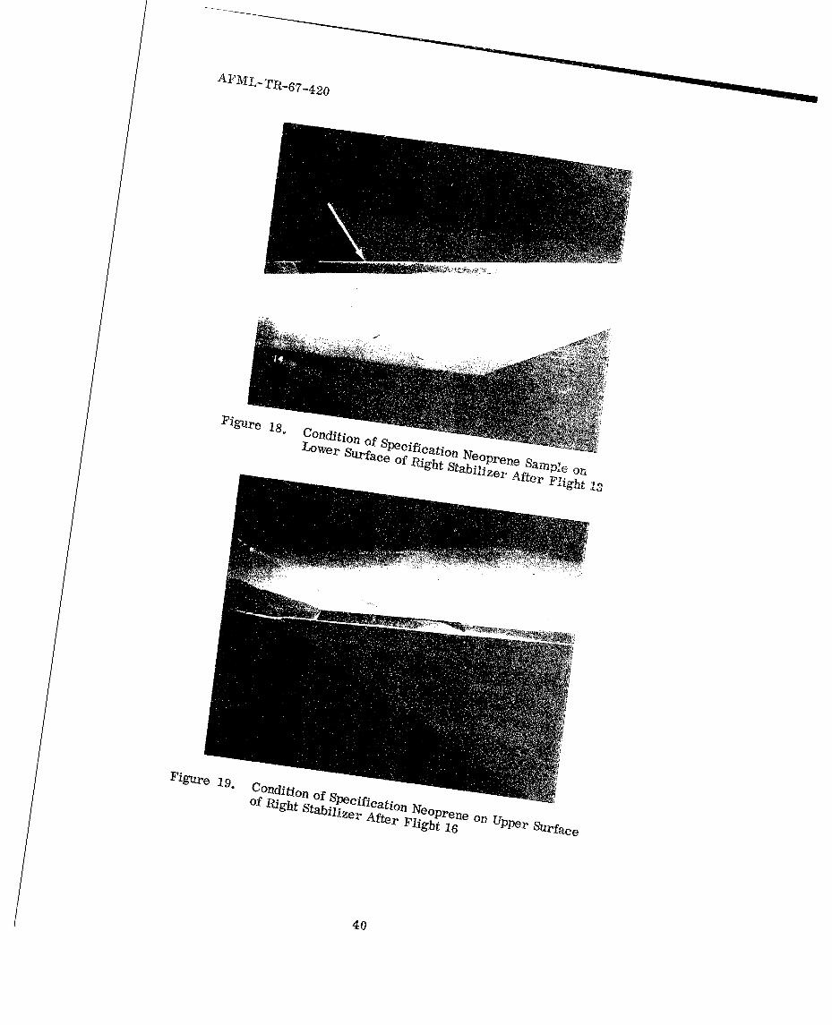
Figure 18.
Conedi j~elfction ofoprSLO~ver auifac Prceficatio
~~~f~~ Neopreni1 ifct~~Nep e Sa Uppe o
zer Fte light 16 e Surface
40

AFML-TR-67-420
4,m
Figure 20. Condition of Specification Neoprene on Lower Surfaceof Right Stabilizer After Flight 16
Figure 21. The Clear Urethane Sample on Leading Edge Shows anApproximate One-Inch Peel at End of Flights; the AdjacentPigmented Urethane on Stabilizer Shows No Adverse Effectsat the End of Program
41

AFML-TR-67-420
Figure 22. The Clear Urethane on Right Stabilizer Had No VisibleAdverse Effects and the Pigmented Urethane Inboard ofClear Urethane Had Approximately One-fourth of the ShoePeeled at the End of Testing
Figure 23. Peeled Segment of Pigmented Urethane on Right StabilizerAfter Last Thunderstorm Flight
42

AFML-TR-67-420
Figure 24. Final Condition of Pigmented Urethane Sample on LowerSurface of Right Stabilizer
Figure 25. Peeling of Clear Urethane on Right Stabilizer Indicated byArrow Was Attributed to Overlapping of the Nickel Sample
43

AFML-TR-67-420
Figure 26. Sections of Clear Urethane Tape (1) Were Torn FromSample on Right Stabilizer During Hail Encounter onFlight 7 and Clear Urethane (2) Was Peeled an AdditionalAmount on the Inboard Edge
Figure 27. Close-up of Damage to Clear Urethane on Lower Surface ofRight Stabilizer After Flight 7
44

AFML-TR-67-420
Figure 28. After Flight 16 the Clear Urethane on Right Stabilizer wasBeing Peeled Intact With No Visible Erosion of the Surface
Figure 29. Clear Urethane on Lower Surface of Right Stabilizer Was AlsoPeeling Intact With No Wear on the Surface of the Material
45

AFML-TR-67-420
Figure 30. Pigmented Urethane and Clear Urethane on Left StabilizerCompleted the Tests With No Adverse Effects
Figure 31. First Sign of Breakdown of Nickel Sample on Leading Edge ofVertical Stabilizer After Flight 7
46
AFML-TR-67-420
Figure 32. Increased Damage to Nickel Sample on Vertical Stabilizeras of Flight 16
Figure 33. Approximately Two-thirds of the Nickel Sample on the RightSide of the Vertical Stabilizer Was Lost by the End ofProgram; the Urethane Sample Above the Nickel HadLittle Damage
47

AFML-TR-67-420
Figure 34. Damage to Nickel Sample on Right Stabilizer UponCompleting Tests
Figure 35. All Urethane Tape on Upper Surface of Left StabilizerWas Lost During Flight 7
48

AFML-TR-67-420
Figure 36. Urethane Tape Left on Lower Surface of Left StabilizerAfter Flight 7
Figure 37. Urethane Tape Remaining on Lower Surface of RightStabilizer After Hail Encounter During Flight 7
49

AFML-TR-67-420
~, . .
Figure 38. Estane on Inboard Edge of Upper Surface on Left StabilizerPeeled as a Result of Hail Encounter on Flight 7
Figure 39. Estane on Lower Surface of Left Stabilizer Received SlightDamage During Flight 7
50
AFML-TR-67-420
Figure 40. Additional Peeling of Estane on Upper Surface of LeftStabilizer After Flight 13
Figure 41. Damage to Estane on Lower Surface of Left StabilizerAfter Flight 13
51

AFML-TR-67-420
Figure 42. Estane Boot Almost Completely Peeled From Left Stabilizerand Adjacent Neoprene With Insignificant Amount Remainingon Leading Edge on Flight 16
Figv.re 43. Damage to Estane and Neoprene on Lower Surface of LeftStabilizer on Flight 16
52

[L-TR-67-420
Figure 44. Slightly Peeled Section of Estane on Upper Surface ofRight Stabilizer
Figure 45. Corner of Estane Pulled Slightly From Lower Surfaceof Right Stabilizer
53

AFML-TR-67-420
Figure 46. Neoprene on Upper Surface of Right Stabilizer Eroded AwayDuring Flight 7 While Adjacent Estane Received No Damage
As
Figure 47. Neoprefte on Lower Surface of Right Stabilizer Eroded FromAircraft on Flight 7
54

AFML-TR-67-420
Figure 48. One Arrow Points to One of the Cuts in the Leading Edge ofNeoprene on Left Stabilizer and the Second Arrow Indicatesthe Damage to the Hycar Boot During Flight 7
Figure 49. Damage to Neoprene and Hycar Boots on Lower Side ofLeft Stabilizer After Flight 7
55

AFML-TR-67-420
Figure 50. Increased Deterioration of Neoprene and Hycar Boots onLeft Stabilizer Observed By Flight 13
Figure 51. Damage to Neoprene and Hycar Boots on Lower Surface ofLeft Stabilizer After Flight 13
56

AFML-TR-67-420
Figure 52. Peeling of Hycar Boot on Right Stabilizer During Flight 3
Figure 53. Hail Encounter on Flight 7 Removed Almost All the HycarBoot From Upper Surface of Right Stabilizer
57

AFML-TR-67-420
Figure 54. Severely Damaged Hycar Boot on Lower Surface ofRight Stabilizer After Seventh Thunderstorm PenetrationMission
Figure 55. Three-fourths of Hycar Boot Removed From Upper Surfaceof Left Stabilizer During Flight 16
58
AFML-TR-67-420
Figure 56. Edge of Slit in Deicing Boot Frayed After Flight 2
Figure 57. One-Inch Square Section of Deicing Boot on RightStabilizer Lost During Flight 2
59

AFML-TR-67-420
Figure 58. Deicing Boot on Left Wing Root With Ruptured Section
Figure 59. Increased Failure of Deicing Boot on Left Wing AfterFlight 3
60

AFML-TR-67-420
Figure 60. Severe Damage to Deicing Boot Caused by Hail and IceCrystal Impingement During Flight 7
Figure 61. Significant Damage to Deicing Boot on Left Wing Caused byHail and Ice Crystal Encounter on Flight 7
61

AFML-TR-67-420
Figure 62. Severe Breakdown on Deicing Boot on Right Wing ObservedAfter Flight 13
Figure 63. Increased Visible Erosion of Left Wing Deicing BootAfter Flight 13
62

AFMI,•TR-6 7 -420
Figure 64. Complete Breakdown' of Deicinkg Boot Onl Left Wing After
Figre 5. ect~n f ~icing Boot On Lower Surface of Left Wing
Received Little Damfage o lgt1
63

AFML-TR-67-420
Figure 66. Surface of Deicing Boot on Upper Leading Edge of WingSeverely Damaged During Flight 16
Figure 67. Surface of Deicing Boot on Lower Surface of Right WingLeading Edge Not Damaged as Much as the Section on Topof Wing
64

AFML-TR-67-420
Figure 68. Goodrich Samples 1 and 2 on Left Wing Tip Show LittleAdverse Effect After Flight 16; the Arrow Indicates SlightDamage to Inboard Edge of Sample 1
Figure 69. Final Damage Received by Goodrich Samples on Left Wing Tip
65

AFML-TR-67-420
Figure 70. Goodrich Samples 3 and 4 on Leading Edge of Right WingReceived Damage During Flight 7; the Arrow Points to aCut on Leading Edge in Sample 3
SiI : i "I Hii;;:
Figure 71. Inboard Sample on Right Wing Tip With Torn Leading EdgeAfter Flight 13
66

AFML-TR-67-420
Figure 72. Samples 3 and 4 on Right Wing Tip After Flight 16
Figure 73. Leading Edge of Inboard Sample on Right Wing Tip Removed31 May; Leading Edge of Outboard Sample Peeled FromHalf of Shoe
67

AFML-TR-67-420
Figure 74. Damage to Goodrich Sample on Noseboom Mount DuringThree Flights
68

UNCLASSIFIEDSecurity Classification
DOCUMENT CONTROL DATA - R & D(Security classification of title, body of abstract and indexing annotation must be entered when the overall report is classified)
1. ORIGINATING ACTIVITY (Corporate author) 2a. REPORT SECURITY CLASSIFICATION
Air Force Materials Laboratory Unclassified
Wright-Patterson Air Force Base, Ohio 2b. GROUP
3. REPORT TITLE
FLIGHT TEST-WHIRLING ARM CORRELATION OF RAINEROSION RESISTANCE OF MATERIALS
4. DESCRIPTIVE NOTES (Type of report and inclusive dates)
February 1967 to June 19675. AUTHOR(S) (First name, middle initial, lasi name)
George F. Schmitt, Jr.
6. REPORT DATE 7a. TOTAL NO. OF PAGES 17b. NO. OF REFS
August 1968 79 48a. CONTRACT OR GRANT NO. 9a. ORIGINATOR'S REPORT NUMBER(S)
b. PROJECT NO. 7340 AFML-TR-67-420
Task No. 734007 Sb. OTHER REPORT NO(S) (Any other numbers that may be assignedthis report)
d.
10. DISTRIBUTION STATEMENT This document is subject to special export controls and eachtransmittal to foreign governments or foreign nationals maybe made only with prior approvalof the Elastomers and Coatings Branch, MANE, Nonmetallic Materials Division, Air ForceMaterials Laboratory, Wright-Patterson Air Force Base, Ohio 45433.11. SUPPLEMENTARY NOTES 12. SPONSORING MILITARY ACTIVITY
Air Force Materials LaboratoryWright-Patterson Air Force Base, Ohio
13. ABSTRACT
The exposure results of ten experimental rain erosion resistant coatings on an F-100Faircraft which penetrated thunderstorms as part of the Project Rough Rider flight testshave been correlated to whirling arm erosion simulation results. The rankings of theerosion resistance of materials determined on the whirling arm were similar for the samematerials in actual flight exposures. These flights confirmed the applicability and superiorityof the electroplated nickel and polyurethane coatings to protect aircraft leading edges andhelicopter rotor blades from the effects of rain erosion. Because the results from thewhirling arm technique and the flight tests were similar, the whirling arm is considered tobe a good research tool for exploratory development of rain erosion resistant materials.These results reconfirm previous correlations of whirling arm rain erosion results with air-craft flight tests.
(The distribution of this abstract is unlimited.)
DDD NFOV .'1473 UNCLASSIFIED
Security Classification

UNCLASSIFIEDSecurity Classification
14. LINK A LINK B LINK CKEY WORDS
ROLE WT ROLE WT ROLE WT
Rain erosionFlight testWhirling armPolyurethaneElectroplated nickel
UNCLASSIFIEDSecurity Classification