
New Insights on the Corrosion Resistant Delhi Iron Pillar
30
0 2001 NML Jamshedpur 831 007, India; Metallurgy in India: A Retrospective; (ISBN: 81-87053-S6-7); Eds: P. Ramachandra Rao and N.G. Goswami; pp. 104-133. New Insights on the Corrosion Resistant Delhi Iron Pillar R. Balasubramaniam Department of Materials and Metallurgical Engineering, Indian Institute of Technology, • Kanpur 208 016, India. ABSTRACT The 1600-year old Delhi iron pillar (DIP) has attracted the attention of metallurgists and corrosion scientists for its excellent corrosion resistance. The present paper provides new insights on the Delhi iron pillar 'based on the researches of the author. The paper has first addressed the identity of Chandra and the. original location of the pillar, Vishnupadagiri. Analysis of the archer-type gold coins of the Imperial Guptas provided that Chandra should be identified with Chandragupta II Vikramaditya. The original location of the pillar has been identified as Udayagiri in Central India based on archaeological evidences. The engineering details of the pillar have been described, including the. decorative bell capital. The manufacturing method of the pillar by side way forge-welding small lumps of iron with the pillar resting in the horizontal position has been described. Finally, the corrosion resistance of the pillar has been addressed in detail. The earlier theories of corrosion resistance have been briefly reviewed. The microstructure of DIP iron has been explained..The role of slag particles in the matrix of the DIP iron in enhancing the passive film formation has been briefly discussed. Characterization of the DIP's rust by modern techniques has clearly established that the major constituents of the scale were crystalline iron hydrogen phosphate hydrate (FePO 4.H3 P0,,. 41-12 0), a-, y-, 8-Fe00H and magnetite. The iron oxide/oxyhydroxides were present in the amorphous form. The process of protectiye rust formation on DIP iron has been outlined based on the rust analysis. Initially, the corrosion rate of iron is high due - to the presence of the slag particles. This results in enhancement of surface P content. In the presence of P, the formation of a protective amorphous compact layer of 5-Fe0OH, next to the metal surface, is catalyzed and this confers the 104
Transcript of New Insights on the Corrosion Resistant Delhi Iron Pillar
0 2001 NML Jamshedpur 831 007, India; Metallurgy in India: A Retrospective; (ISBN: 81-87053-S6-7); Eds: P. Ramachandra Rao and N.G. Goswami; pp. 104-133.
New Insights on the Corrosion Resistant Delhi Iron Pillar
R. Balasubramaniam Department of Materials and Metallurgical Engineering, Indian Institute of Technology,
• Kanpur 208 016, India.
ABSTRACT
The 1600-year old Delhi iron pillar (DIP) has attracted the attention of metallurgists and corrosion scientists for its excellent corrosion resistance. The present paper provides new insights on the Delhi iron pillar 'based on the researches of the author. The paper has first addressed the identity of Chandra and the. original location of the pillar, Vishnupadagiri. Analysis of the archer-type gold coins of the Imperial Guptas provided that Chandra should be identified with Chandragupta II Vikramaditya. The original location of the pillar has been identified as Udayagiri in Central India based on archaeological evidences. The engineering details of the pillar have been described, including the. decorative bell capital. The manufacturing method of the pillar by side way forge-welding small lumps of iron with the pillar resting in the horizontal position has been described. Finally, the corrosion resistance of the pillar has been addressed in detail. The earlier theories of corrosion resistance have been briefly reviewed. The microstructure of DIP iron has been explained..The role of slag particles in the matrix of the DIP iron in enhancing the passive film formation has been briefly discussed. Characterization of the DIP's rust by modern techniques has clearly established that the major constituents of the scale were crystalline iron hydrogen phosphate hydrate (FePO4.H3P0,,. 41-120), a-, y-, 8-Fe00H and magnetite. The iron oxide/oxyhydroxides were present in the amorphous form. The process of protectiye rust formation on DIP iron has been outlined based on the rust analysis. Initially, the corrosion rate of iron is high due -to the presence of the slag particles. This results in enhancement of surface P content. In the presence of P, the formation of a protective amorphous compact layer of 5-Fe0OH, next to the metal surface, is catalyzed and this confers the
104
R. Balasubramaniarn
initial corrosion resistance. The critical factor aiding the superior corrosion resistance of the Delhi iron pillar, however,, is .the formation of iron hydrogen phosphate hydrate, as a thin layer next to the metal-metaloxide'interfaCe. The formation of.the crystalline modification of this phosphate from the amorphous form is aided by alternate wetting and drying cycles the environmental factor). The rate of corrosion is further lowered due to the low porosity content of the crystalline phosphate phase. The passive film formation on the Delhi iron pillar has been contrasted with rusting bf normal and weathering steels.
Key words : Delhi iron pillar, Engineering design,. Forge welding, Corrosion resistance, Mixed potential theory, Rust characterization,
Iron hydrogen phosphate, Passive film.
INTRODUCTION
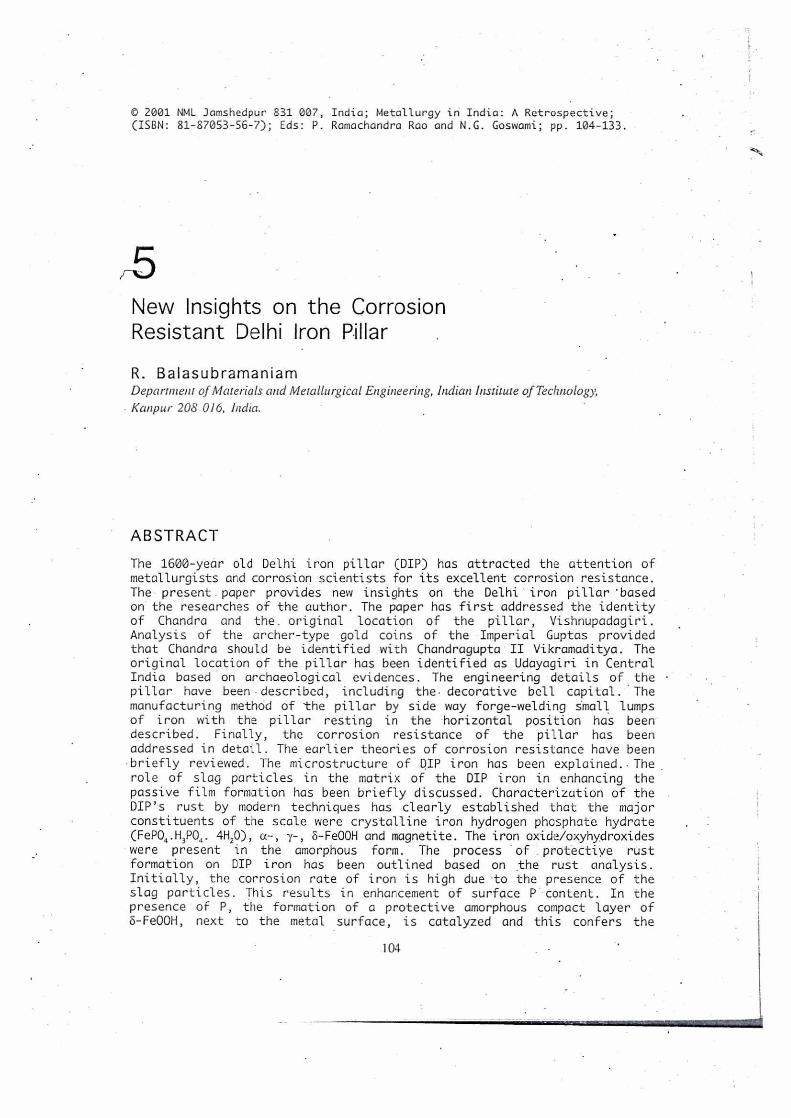
The Delhi iron pillar (Fig. 1) is testimony to the high level of skill achieved by the ancient Indian iron smiths in the extraction and processing of iron. It has attracted the attention of archaeologists and corrosion technologists as it has withstood corrosion for the last 1600 years. It is singularly featured on the emblem of both the National Metallurgical Laboratory (NML) and the Indian institute of Metals, thereby signifying its premier position in representing India's metallurgical pride and heritage. The first systematic scientific study of the Delhi iron pillar (DIP) was undertaken by Hadfieldm. Ever since, there have been a growing number of studies wherein several aspects of the DIP have been discussed. In the centenary year of the Archaeological Survey of India (ASI) in 1961, the Delhi iron pillar was studied in detail with the co-operation of National Metallurgical Laboratory. The buried underground region of the pillar was examined by archaeological excavation. Moreover, a relatively large iron sample was obtained from the pillar and subjected to several metallurgical analyses at the NML. The results of these scientific studies have been summarized in a special issue of the NML Technical Journal (Volume 5, 1963). These studies provided the firm foundation for all later scientific studies. A review of the pillar's corrosion resistance appeared in 1970 (Wranglen)m. Anantharamanm has published the known scientific .facts about the DIP in the form of a book. The present paper will present new insights on the DIP based on research carried out at lIT Kanpur in the last decade of the last millenium.
HISTORY
Identity of Chandra
Among the several inscriptions on the pillar, the oldest (and also the largest) is a three-stanza six-line Sanskrit inscription, at a level of about 7 feet from the stone platform, which states that the pillar was erected as a lofty standard in a Vishnu temple on a hill called Vishnupadagiri by a king having the name of Chandra. The theories that have been proposed to identify Chandra have been critically reviewed elsewhereol. The inscription has been dated to between 400 and 450 AD based on the nature of the characters. Therefore, the iron pillar was constructed during the rule of the imperial Guptas in ancient India. The imperial
105

New Insights on the Corrosion Resistant Delhi Iron Pillar
'WV:"Wteg.44:
Fig. 1 : The Delhi iron pillar. Notice the iron'gilll.bage around the pillar bottom that has been recently constructed. Atf',''7;"1'< 2'
4., y
Gupta monarchs were Chandragupta I, Samudragupta, Chandragupta II, Kumaragupta I and Skandagupta.
In order to identify Chandra, numismatic evidences would be presented. Numismatics provides conclusive proof of the rulers and successors of any dynasty, the lifestyles and the costumes worn by people, the development of script and most impOrtantly, the names, titles and attributes of the rulers. The information available. from numismatic sources is considered definitive and therefore we shall stress the importance of numismatic evidence here. The inscription clearly tells that the king had the name Chandra and this is. the most important clue to determine his identity. There are several gold coin-types in which Chandragupta II Vikramaditya's short name of Chandra is inscribed. This line • of argument has already been stated by many commentators, but this argument alone is not sufficient. The additional crucial . argument for the unambiguous identification Of Chandra from numismatic sources is presented below. The most popular gold coin type which was issued by the Gupta monarchs from the time of Samudragupta was the archer type gold coin. In fact, the archer coin type seems to have been the only issue of some of the later Gupta monarchs.
106
•
R. Bala. subramaniam
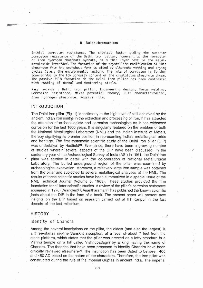
The obverse in these coins depicts the king with a bow and a short name of the issuing king. (Fig. 2). The garuda emblem is another. regular feature of these coins as these coins signify the warrior attributes of the king holding the bow and 'arrow. The most interesting aspect about the archer coin type is that the king's short name is inscribed in the obverse field (i.e., region of the figure) with the full name and title. of the monarch provided in the circular legend: In the case of Samudragupta's archer coins, Samudra is found below his left arm clear of the bow. In all the different types of archer gold coins of Chandragupta II, the short name of the king is inscribed as Chandra while the king's complete title and name is provided in the circular legend. Therefore, it is amply clear that Chandragupta II.Vikrarnaditya was called in short as Chandra and this is attested firmly by his most popular coin-type. In the archer coins of Kumaragupta I, the king's name provided in the obverse field is Kumara or Ku or absent in some, but appearing as Kumaragupta in the circular legend. Kurnaradupta''s successor was Skandagupta, who also issued the• archer coin-type in which his name appears in the field as Skanda and his full name* is provided in the legend in the obverse. The dates of the Gupta monarchs after Skandagupta and their line of succession are not known with certainty. However, the existence of the later Gupta monarchs and rivals is knoWn from the archer coin types of the later Guptasm. One of the known rivals of Skandagupta by the name of Purugupta issued archer type coin with his name in the obverse field mentioned as Puru and the biruda Srivikramah on the reverse. The rebellious son of Kumaragupta I, Ghatotkachagupta issued an archer type coin with his name Ghato on the obverse field. Narasimhagupta I Baladitya whose short name was Nara succeeded Skandagupta. He was followed by Kumaragupta H Kramaditya with the short name Ku and the legend Kramaditya in the--reverse. He was succeeded by Budhagupta Vikramaditya whose archer coin type spells his name as Budha and the legend Srivikramah on the reverse. Vainyagupta Dvadasaditya succeeded Budhagupta and his archer coins have his name Va(in)ya with the reverse legend Dvadasaditya. The last known imperial Gupta ruler was Vishnugupta Chandraditya whose archer type gold coins provides his name as Vishnu in the obverse field and the legend Srichandraditya in the reverse. Therefore, analysis of the archer
Fig. 2 : Archer type gold coin of Chandragupta II Vikramaditya. In the obverse, the short name (Chandra) of the king is provided below his left arm while his full name appears•in the circular legend. Photograph courtesy: Ellen M. Raven.
107
New Insights on the Corrosion Resistant Delhi Iron Pillar
coin type of the imperial Guptas provides conclusive evidence that Chandra was the short name for Chandragupta II Vikramaditya'41..
Location of Vishnupadagiri
All opinions on the identity of the Vishnupadagiri have been critically summarized elsewhere14,51. Some opinions have been proposed with little supporting evidence, like a bathing ghat in Hardwar in the vicinity where the footmark of Vishnu is imprinted. Literary evidences quoted in the Ramayana and the Mahabharata
Aiave also been utilized to identify Vishnupadagiri near river Beas. The . next major idea identifying Mathura as Vishnupadagiri was proposed by Smith's}. However, Mathura was a place of great Buddhist religious activities during the Gupta period. This is attested by the excellent Buddha statues in bronze and stone of the Mathura school dating to the time of Chandragupta II Vikramaditya'41. 'Therefore, we need to seek Vishnupadagiri in the region which was well within the territory of Chandragupta II and which was also renowned for Vaishnavite worship from times even before the Gupta period.
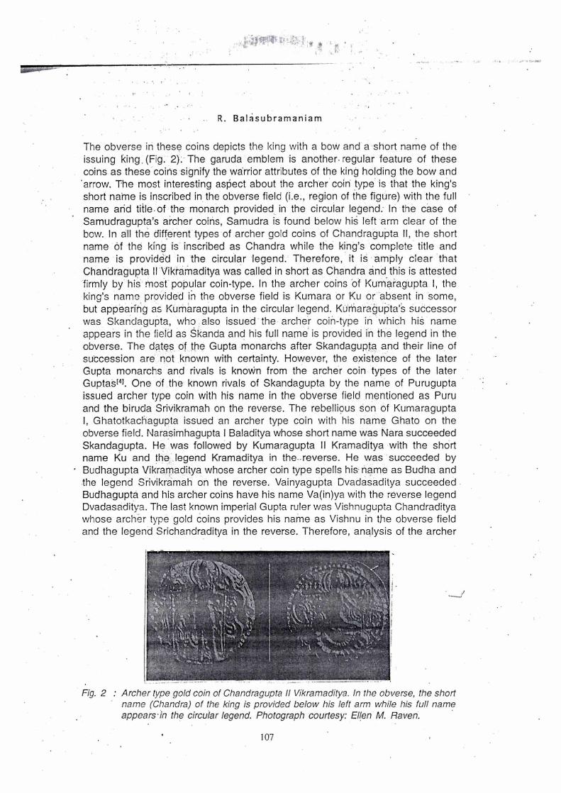
It is reasonable to propose that Vishnupadagiri must have been located in one of the important cities of the Gupta dominion, especially in the reign of Chandragupta II Vikramaditya. The center that satisfies this important criterion is the region comprising present Udayagiri-Besnagar-Vidisha-Sanchi. This was one of the important centers of trade and religious activities in ancient India, even prior to the Guptas. This region regulated trade between the west, east, north and south and it was extremely prosperous. This region was especially famous for religious worship. The inscription on the Heliodorous pillar in Besnagar, at the foothills of Udayagiri, conclusively proves that Vaishnavism was very popular in this region. The importance of this region for Vaishnavism and for the religious activities of the Guptas is attested by the fact the Guptas created their first rock-cut temples at Udayagiri. The Udayagiri cave temples also possess the unique distinction of being the only works that can be personally associated with one Gupta monarch, Chandragupta II Vikramaditya. The presence of Chandragupta in this region is attested by his inscriptions. Harlem notes that "the nearest that we can actually come to visualizing an Imperial Gupta monarch is here, among the low hills and the wide plains of Central India. Chandragupta II must have almost certainly have walked, surrounded by his retinue, along the narrow roads that run past the caves and made his devotions here". The most well-known and imposing of the Udayagiri sculptures is the great panel of the Varaha (Boar) incarnation of Vishnu designated as Cave 5 (Fig. 3). In this bas-relief, the standing figure of Varaha is shown stepping on a rock with his left foot raised and the knee bent at right angle. Harlem has explained other interesting aspects of this panel. All Gupta scholars are in agreement that the second kneeling human figure in front of Varaha is Chandragupta II Vikramaditya. It must be noted in the bas-relief that Varaha has his left foot firmly placed on what earlier commentators have stated to be a rock. However, the appearance of the object on which Varaha sets his foot on is more like a mountain, the living image of Vishnupadagiri. It must also be noticed that the rock, on which Varaha sets his foot on, contains
108
R. Balasubrarnaniam
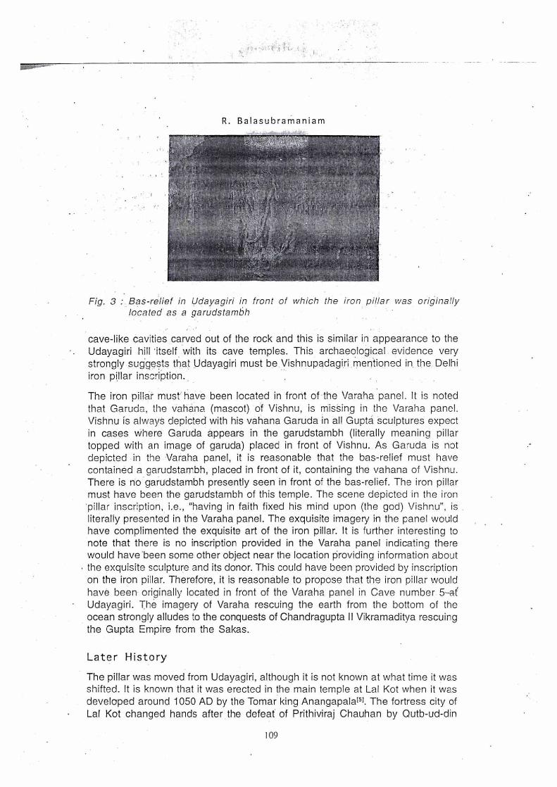
Fig. 3 :. Bas-relief in Udayagiri in front of which the iron pillar was originally located as a garudstambh
cave-like cavities carved out of the rock and this is similar in appearance to the Udayagiri hill *itself with its cave temples. This archaeological evidence very strongly suggests that Udayagiri must be. Vishnupadagiri mentioned in. the Delhi iron pillar inscription..
The iron pillar must' have been located in front of the Varaha panel. It is noted that Garuda, the vahana (mascot) of Vishnu, is missing in the Varaha panel. Vishnu is always depicted with his vahana Garuda in all Gupta sculptures expect in cases where Garuda appears in the garudstambh (literally meaning pillar topped with an image of garuda) placed in front of Vishnu. As Garuda is not depicted in the Varaha panel, it is reasonable that the bas-relief must have contained a garudstambh, placed in front of it, containing the vahana of Vishnu. There is no garudstambh presently seen in front of the bas-relief. The iron pillar must have been the garudstambh of this temple. The scene depicted in the iron 'pillar inscription, i.e., "having in faith fixed his mind upon (the god) Vishnu", is literally presented in the Varaha panel. The exquisite imagery in the panel would have complimented the exquisite art of the iron pillar. It is further interesting to note that there is no inscription provided in the Varaha panel indicating there would have been some other object near the location providing information about the exquisite sculpture and its donor. This could have been provided by inscription on the iron pillar. Therefore, it is reasonable to propose that the iron pillar would have been originally located in front of the Varaha panel in Cave number 5-a( Udayagiri. The imagery of Varaha rescuing the earth from the bottom of the ocean strongly alludes to the conquests of Chandragupta II Vikramaditya rescuing the Gupta Empire from the Sakas.
Later History
The pillar was moved from Udayagiri, although it is not known at what time it was shifted. It is known that it was erected in the main temple at Lal Kot when it was developed around 1050 AD by the Tomar king Anangapala'51. The fortress city of Lal Kot changed hands after the defeat* of Prithiviraj Chauhan by Qutb-ud-din
109
New Insights on the Corrosion Resistant Delhi Iron Pillar
Aibak, the slave army commander of Muhammad Ghori of Ghazni, in 1191 AD. Aibak erected a mosque, between 1192 and 1199 AD, called the Quwwat-ul-Islam (Might of Islam) to commemorate his victory. The pillar currently stands in the open courtyard of this mosque, the first to be built in India. The mosque was built on the base of a temple (which is clearly discernible) that once occupied the site and constructed with materials taken from twenty-se.ven destroyed temples in the nearby vicinity. Archaeological evidence[8] and facts based on temple architecture indicate that the pillar must have been located in the original temple complex in Delhi, but at a different location from the current orre. In the process
"of re-assembling the iron pillar after the destruction of the temple, a part of the pillar, which was initially buried underground, has been placed above the ground level151. The pillar has been, ever since, lying in this location.
ENGINEERING DESIGN
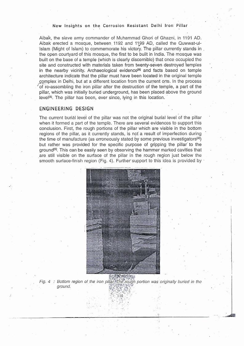
The current buriAl level of the pillar was not the original burial level of the pillar when it formed a part of the temple. There are several evidences to support this conclusion. First, the rough portions of the pillar which are visible in the bottom regions of the pillar, as it currently stands, is not a result of imperfection during the time of manufacture (as erroneously stated by some previous investigators'2]) but rather was provided for the specific purpose of gripping the pillar. to the groundm. This can be easily seen by observing the hammer marked cavities that
.are still visible on the surface of the pillar in the rough region just below the smooth surface-finish region (Fig. 4). Further support to this idea is provided by
Fig. 4 : Bottom region of the iron pikarAtThe-,rough portion was originally buried in the ground.

R. Balasubramaniam
Fig. 5 : Free hand sketch of the pillar by an artist named Mirza Shah Rukh Beg published originally in in Syed Ahmed Khan's Urdu. work Atharsal-Sanadid in 1846 .(Nath 1984).
• the observation that if one were to stand at the level of the start of the smooth section of the pillar, the inscriptions now appear at face level and the person would directly face the inscriptions. Therefore, the pillar must have been buried at this level, as the inscriptions would be otherwise too high for a person standing at the current base of the pillar to read.
Beglarm constructed the stone platform around the base of. the iron pillar in the last century. The habit of clasping the hands around the pillar for "good luck" was present even before Beglar constructed the stone platform. This is seen in one free* hand sketch of the pillar by an artist named Mirza Shah Rukh Beg for publication in Syed Ahmed Khan's Urdu work Atharial-Sanadid in 1846 (Fig. 5). The English translation of this book[91 shows this illustration in which a bearded perSon is clasping the pillar (without the stone platform) at the top of the rough section. In such a case, it must have resulted in a polished band just at the start of the smooth section and this is the reason why the region just at the start of the smooth section appears smooth and even surfaced. This polished band is also clearly noticed in earlier published photographs of the pillar taken beforemoll and afterol the construction of the stone platform.
Dimensional Analysis
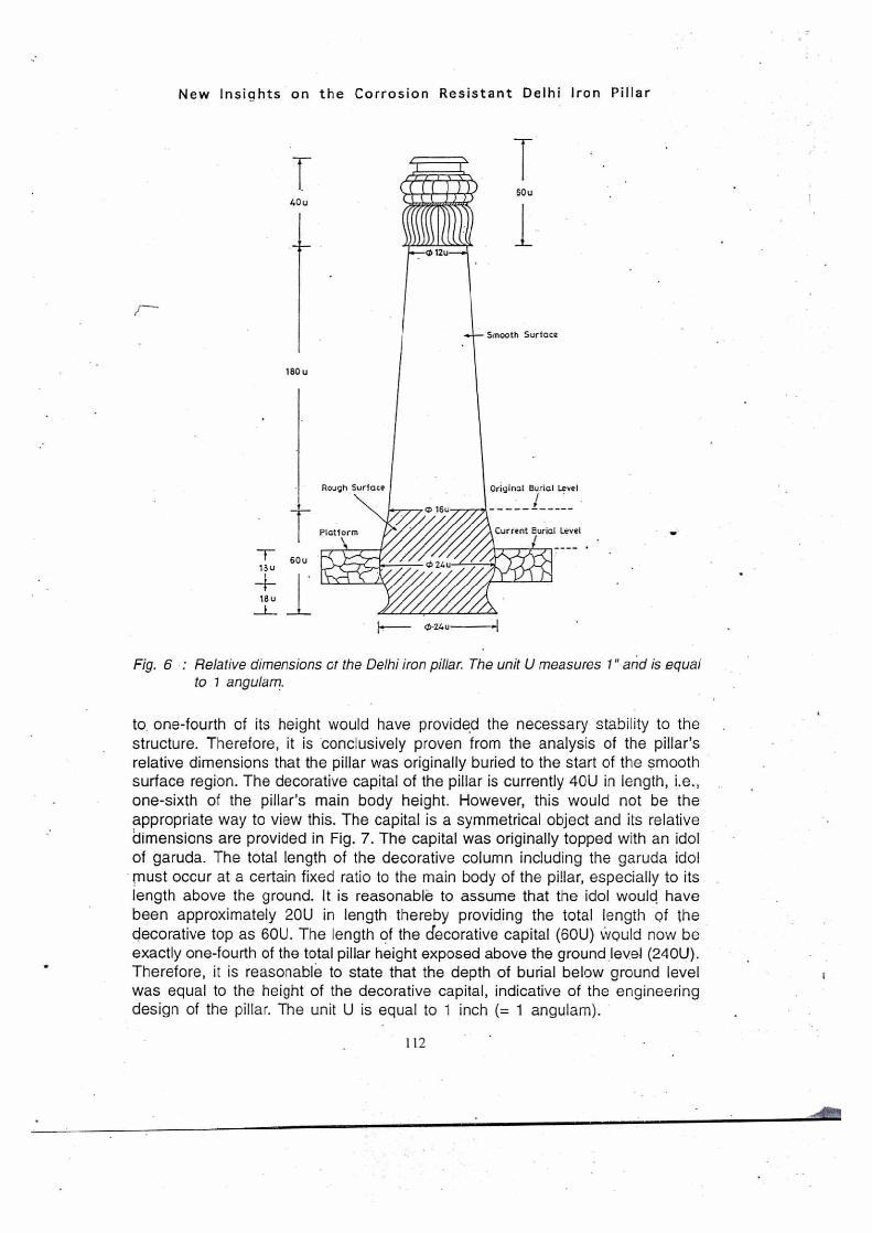
A critical analysis of the dimensions of the main body of the pillar provides conclusive evidence for the original burial level of the pillar and also an appreciation of the pillar's symmetrical designm. If the start of the smooth surface section is taken as the original burial level, the relative dimensions of the pillar are as provided in Fig. 6. The relative dimensions do not resemble any pattern if the present level is considered as the original one. However, the rough surface occupies one-fourth (60U) and •the smooth surface three-fourths (180U) of the pillar main body length, excluding the decorative. top. The burial of the pillar body
4111111■1■1101.
tat
Smooth Surface
180 u
T 60u
18u
4- 18u
Rough Surface Original Burial Level
Platform Current Burial Level
60u 40u
New Insights on the Corrosion Resistant Delhi Iron Pillar
Fig. 6 : Relative dimensions of the Delhi iron pillar. The unit U measures 1" and is equal to 1 angularn.
to. one-fourth of its height would have provided the necessary stability to the structure. Therefore, it is conclusively proven from the analysis of the pillar's relative dimensions that the pillar was originally buried to the start of the smooth surface region. The decorative capital of the pillar is currently 40U in length, i.e., one-sixth of the pillar's main body height. However, this would not be the appropriate way to view this. The capital is a symmetrical object and its relative dimensions are provided in Fig. 7. The capital was originally topped with an idol of garuda. The total length of the decorative column including the garuda idol must occur at a certain fixed ratio to the main body of the pillar, especially to its length above the ground. It is reasonable to assume that the idol would have been approximately 20U in length thereby providing the total length of the decorative top as 60U. The length of the decorative capital (60U) Would now be exactly one-fourth of the total pillar height exposed above the ground level (240U). Therefore, it is reasonable to state that the depth of burial below ground level was equal to the height of the decorative capital, indicative of the engineering design of the pillar. The unit U is equal to 1 inch (= 1 angulam).
112
16u .3
H-
12 u
12u 2u
T .15 8u
(41. 8u _al
, u
1/2u
4u
1/2u
2u _
1/2u _t_
ir 1/2u-1—
5/2 u
• _i_ 1/2u _r_
6u
1/2u
T 4u
1/2 u 1
2u
(1) 12u
I .11
2u ...■••■•••
T 1/3 B
012u
( ct)12u
1Gu
cb 12 u
2u
T 1/4 B
I
3 /4 u
(1) 12u
th 16u
ch 1 6 u
•••
R. Balasubramaniam
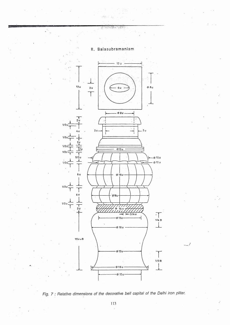
Fig. 7 : Relative dimensions of the decorative bell capital of the Delhi iron pillar.
113
New Insights on the Corrosion Resistant Delhi Iron Pillar
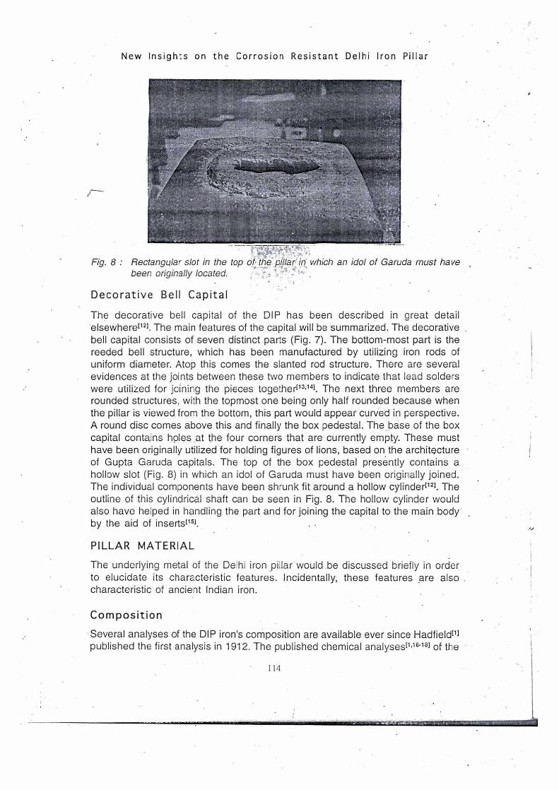
Fig. 8 : Rectangular slot in the top 011ie pillar in which an idol of Garuda must have r.
been originally located.
Decorative Bell Capital
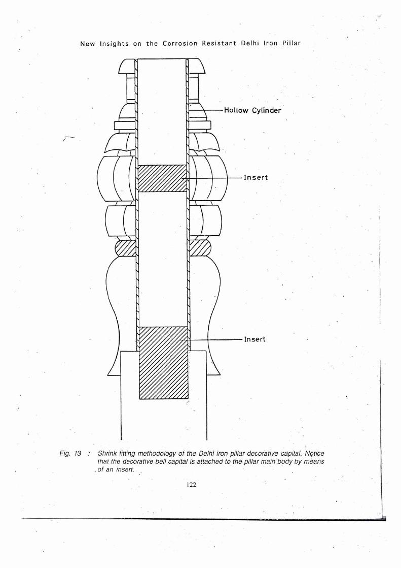
The decorative bell capital of the DIP has been described in great detail .elsewhere["]. The main features of the capital will be summarized. The decorative bell capital consists of seven distinct parts (Fig. 7). The bottom-most part is the reeded bell structure, which has been manufactured by utilizing iron rods of uniform diameter. Atop this comes the slanted rod structure. There are several evidences at the joints between these two members to indicate that lead solders were utilized for joining the pieces together[1304]. The next three members are rounded structures, with the topmost one being only half rounded because when the pillar is viewed from the bottom, this part would appear curved in perspective. A round disc comes above this and finally the box pedestal. The base of the box capital contains holes at the four corners that are currently empty. These must have been originally utilized for holding figures of lions, based on. the architecture of Gupta Garuda capitals. The top of the box pedestal presently contains a hollow slot (Fig. 8) in which an idol of Garuda must have been originally joined. The individual components have been shrunk fit around a hollow cylinder[121. The outline of this cylindrical shaft can be seen in Fig. 8. The hollow cylinder would also have helped in handling the part and for joining the capital to the main body by the aid of inserts(15].
PILLAR MATERIAL
The underlying metal of the Delhi iron pillar• would be discussed briefly in order to elucidate its characteristic features. Incidentally, these features are also characteristic of ancient Indian iron.
Composition
Several analyses of the DIP iron's composition are available ever since Hadfield[1] published the first analysis in 1912. The published chemical analyses[1,16-18] of the
114
OWN
R. Balasubramaniam
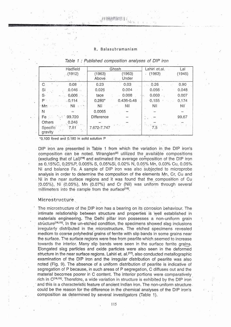
Table I Published composition analyses of DIP iron
•
Hadfield (1912)
.
Ghosh Lahiri .et.al. . (1963)
. .
Lal (1945) (1963)
Above (1963) Under
C • 0:08 0.23 0.03 0.26 0.90
Si 0.046 .. 0.026 0.004 0.056. 0.048
S- 0,006 tace 0.008 0.003 . 0.007
P. .0.114 0.280* 0.436-0A8 0,155 0.174
•Mn Nil - Nii Nil Nil Nil.
N — 0.0065 — — —
Fe • 99.720 Difference — .• — 99.67
Others 0.246 — — — — Specific. gravity
• • 7.81. . 7.672-7.747 • '
' 7. 5
*0.100 fixed and 0.180 in solid solution P
DIP iron are presented in Table 1 from which the variation in the DIP iron's
composition can be noted. Wranglen'2] utilized the (available compositions
(excluding that of Lal)[18' and estimated the average composition of the DIP iron
as 0.15%C, 0.25%P, 0.005% S, 0.05%Si, 0.02% N, 0.05% Mn, 0.03% Cu, 0.05%
Ni and balance Fe. A sample of DIP iron was also Subjected to microprobe analysis in order to determine the composition of the elements Mn, Cr, Cu and
Ni in the near surface regions and it was found that the composition of Cu (0.05%), Ni (0.05%), Mn (0.07%) and Cr (Nil) was uniform through several millimeters into the sample from the surfacer").
Microstructure
The microstructure of the ,DIP iron has a bearing on its corrosion behaviour. The
intimate relationship between structure and properties is well established in materials engineering. The. Delhi pillar iron possesses a non-uniform grain structurer16,191. In the un-etched condition, the specimens showed slag inclusions irregularly distributed in the microstructure. The etched specimens revealed mediOrn to coarse polyhedral grains of ferrite with slip bands in some grains near
the surface. The surface regions were free from pearlite which seemed to increase
towards the interior. Many slip bands were seen in the surface ferrite grains.
Elongated slag particles and oxide particles were also seen in the deformed structure in the near surface regions. Lahiri et. al.071, also conducted metallographic examination of the DIP iron and the irregular distribution of pearlite was also noted (Fig. 9). The absence of a uniform distribution of pearlite is indicative of segregation of P because, in such areas of P segregation, C diffuses out and the
material becomes poorer in C content. The interior portions were comparatively rich in Cr16,191. TherefOre, a Wide variation in structure is exhibited by the DIP iron
and this is a characteristic feature of ancient Indian iron. The non-uniform structure could be the reason for the difference in the chemical analyses of the DIP iron's composition as determined by several investigators (Table 1).
115

New Insights on the Corrosion Resistant Delhi Iron Pillar
The DIP iron was characterized by a relatively high proportion of slag inclusions. The pillar is a solid body1151 with good mechanical strength (yield strength YS of 23.5 tons per sq. in., ultimate tensile strength UTS of 23.9 tons per sq. in. .and 5% elongation)116). The relatively high strength and the similarity of YS and UTS are indicative of the composite structure of the DIP iron. Slag results in the microstructure due to the p.rocessing method employed to obtain iron. Iron was produced in ancient India by solid state reduction of high quality iron ore using charcoal1201. Once the reduction was complete, the iron lumps produced were hammered in order to remove part of the liquid slag formed during the extraction -p-T-Ocess. Some of the slag invariably remained in the bulk of the material and. this is the origin of the entrapped slag inclusions. Moreover, ancient Indian iron samples also contain a small amount of unreduced iron oxides. Generally, silica was sprayed on to the iron that was extracted and this combined with unreduced iron oxide, resulting in the slag fayelite Fe2SIO4. Microstructural investigations on iron produced during the Gupta period show that both slag and unreduced iron oxide were present in the main body of Eran iron[21,22). These unreduced iron oxides also contained carbon, presumably due the charcoal used for the extraction1211. The presence of carbon in these unreduced oxides would render these oxides cathodic in nature with respect to the surrounding matrix.
A very interesting feature concerning the presence of slag particles in ancient Indian iron is that the pearlite volume fraction is relatively greater near the slag particles. Microstructures containing 0.2% to 0.3% C were present next to the slag particles, in addition to carbon-free grains (Ghosh 1963). In the near vicinity of slag inclusions, the regions are depleted in P and these are the regions where C will concentrate. The slag regions would act a's cathodic reaction sites during corrosion due to the large volume fraction of cementite present at 'these locations.
R. Balasubramaniam
' Origin for P in Metal
It will be shown iater that the presence of P is crucial to the corrosion resistance of DIP. As the DIP iron contains a larger amount of P than.modern-day steel, the reason for the high P contents in the iron is briefly addressed. interestingly, in nearly all published ancient Indian iron compositions, a relatively larger percentage of P (compared to modern steels) can be noted (Table 1). Modern steels cannot tolerate such high P contents, as they would be susceptible to hot shotness. While it was earlier believed that P in ancient steels comes from slag inclusions[231, recent developmentS in slag chemistry help in understanding the probable reason. The relatively higher P content in ancient iron is related to the kind of slag that was created 'in the extraction process by solid state reduction. Lime was not added in thd ancient Indian furnaces, unlike in today's blast furnaces, and therefore the slags were essentially fayelite (iron orthosilicates Fe2SiO4). This is also corroborated by available compositions of ancient iron-making slags from archaeological excavation sites[18]. The slags do not contain lime"). The removal of P from the metal into the slag is facilitated by the basic components (for example, FeO and CaO) in the slag. The efficiency of removal of P from metal is much higher for •Ca0 compared to FeO in the slag. These facts are well established• in slag chemistry1241. Therefore, the absence of CaO in the slags leads to a lower efficiency for removal of P from the metal, which invariably must have resulted in higher P contents in ancient Indian irons. Thermodynamic analysis of P removal from ancient and modern iron also provides the same answer[251. As the entrapped slag present in the ancient Indian iron is generally fayelitic without any CaO, thermodynamics dictates that a higher amount of P should remain in solid solution in Fe. This must be one of the reasons for the presence of higher P in ancient Indian iron. It must also be noted that there indications that P addition was also intentional. For example, Buchanan[261, in his detailed description of steel making in Karnataka in the 18th century, describes that in one primitive furnace operated at Devaraya Durga, conical clay crucibles were filled with a specific amount of wood, from the barks of a plant cassia auriculata, pieces of wrought iron, then sealed and fired. The bark of this plant contains a high content of P, extracted by osmosis from the ground.
MANUFACTURING METHODOLOGY
The DIP weighs nearly 6000 kgs and is approximately 23 feet high. Therefore, the manufacture of the pillar was a marvelous engineering achievement. Thd handling of the pillar body is certainly an important aspect that would have been addressed and planned even before the construction of the pillar was attempted. In fact, the intricate design and construction of the pillar indicates that the Gupta craftsmen were good engineers who must have planned the entire manufacturing operation well in advance of the actual manufacturing procedure. The manufacturing methodology of the main body of the pillar will be briefly addressed["). The individual iron lumps obtained from the metal extraction process had to be joined in order to produce large objects. This was accomplished by forge welding. Forge welding is an operation in which iron lumps are joined'
117

Iron lump
Handling clamp
rrn Furnace Die/Anvil
Rotating peds
New Insights on the Corrosion Resistant Delhi Iron Pillar
together by forging them in the hot state such that fusion is obtained between them. This process initially involves heating of the lumps to a relatively high temperature in a bed of charcoal in order to make them soft and amenable for deformation. One lump is then placed on top of another and force is applied in order to weld them in the solid state. As the force is dynamic is nature, it is called forge welding.
Forge welding of the luMps to the pillar body could be performed. with the pillar either in the vertical or horizontal position during forging. The vertical forge-vv?e-Iding technique could be briefly described as follows. The iron lumps'are forge welded on to the bocy of the pillar by applying the force in the vertical direction. Once the pillar had attained a certain height, the earth is covered up to that point and the process further repeated. In the horizontal forge welding technique, the iron lumps are forged on to the pillar lying in the horizontal direction. The lumps can be either forged on to the cross section of the pillar or on the side of the pillar (Fig. 10), which is in the horizontal position.
The likely method by which the Delhi iron pillar could have been manufactured is briefly described to provide an overview of the process. This is based on a critical analysis of the various aspects concerning the manufacturing methodology like hammering method, heating method, forging method, use of inserts, use of dies and ease of handling[151. The heated iron lumps were placed on the side surface of the pillar and hammered on to the same by the use of hand-held hammers. The addition of metal would have been sideways with the pillar lying in the horizontal direction (Fig. 10). The pillar's vertical and horizontal movements would have been aided by handling clamps provided on the surface of the pillar, the protruding portion of which must have been chiseled away during the surface
Fig. 10 Horizontal forge welding technique for manufacturing the pillar' main body.
118
R. Balasubramaniam
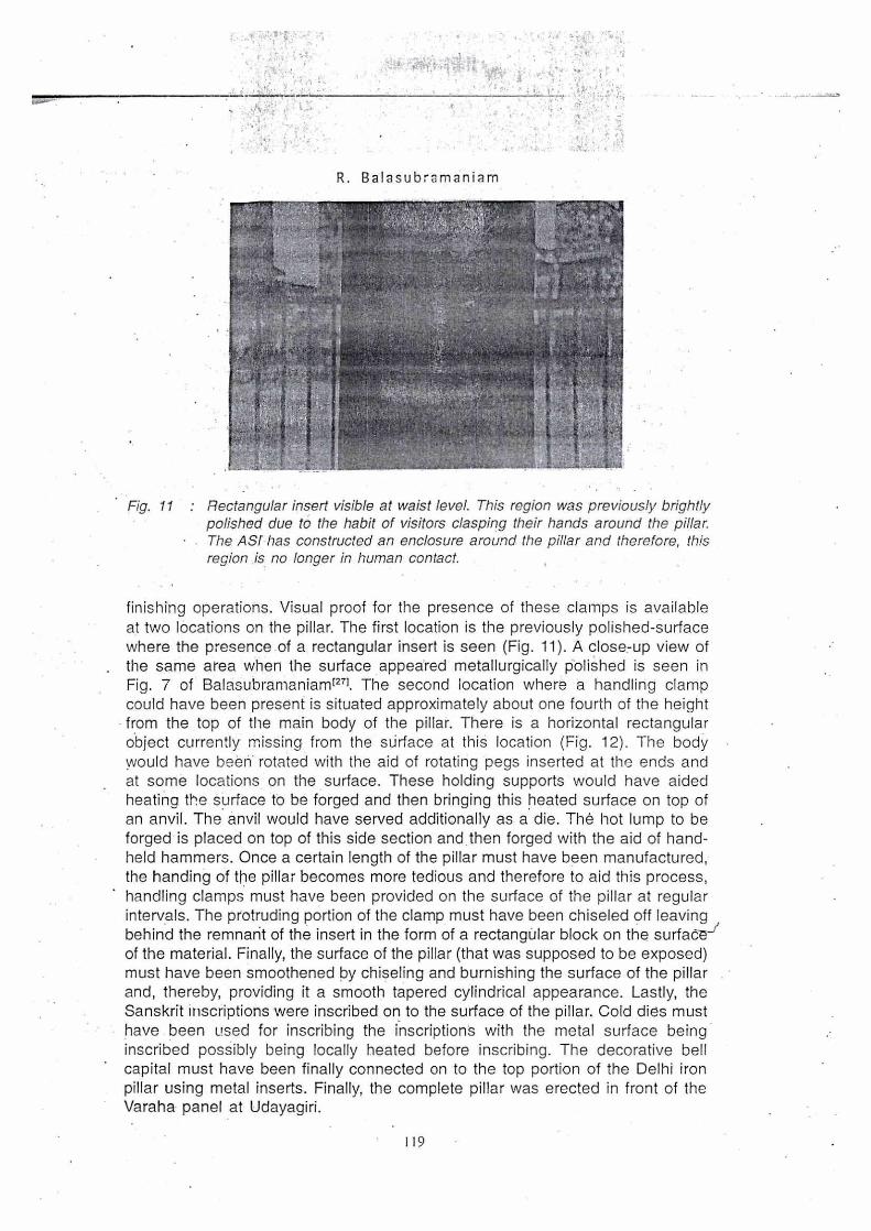
Fig. 11 : Rectangular insert visible at waist level. This region was previously brightly polished due to the habit of visitors clasping their hands around the pillar.
• The AST has constructed an enclosure around the pillar and therefore, this region is no longer in human contact.
finishing operations. Visual proof for the presence of these clamps is available at two locations on the pillar. The first location is the previously polished-surface where the presence of a rectangular insert is seen (Fig. 11). A close-up view of the same area when the surface appeared metallurgically polished is seen in Fig. 7 of Balasubramaniarn[27] The second location where a handling clamp could have been present is situated approximately about one fourth of the height from the top of the main body of the pillar. There is a horizontal rectangular object currently missing from the surface at this location (Fig. 12). The body • would have been- rotated with the aid of rotating pegs inserted at the ends and at some locations on the surface. These holding supports would have aided heatina the surface to be forged and then bringing this heated surface on top of an anvil. The anvil would have served additionally as a die. The hot lump to be forged is placed on top of this side section and.then forged with the aid of hand-held hammers. Once a certain length of the pillar must have been manufactured, the handing of the pillar becomes more tedious and therefore to aid this process, handling clamps must have been provided on the surface of the pillar at regular intervals. The protruding portion of the clamp must have been chiseled off leaving behind the remnant of the insert in the form of a rectangOlar block on the surfaces of the material. Finally, the surface of the pillar (that was supposed to be exposed) must have been smoothened by chiseling and burnishing the surface of the pillar and, thereby, providing it a smooth tapered cylindrical appearance. Lastly, the Sanskrit inscriptions were inscribed on to the surface of the pillar. Cold dies must have been used for inscribing the inscriptions with the metal surface being inscribed possibly being locally heated before inscribing. The decorative bell capital must have been finally connected on to the top portion of the Delhi iron pillar using metal inserts. Finally, the complete pillar was erected in front of the Varaha panel at Udayagiri.
119

New Insights on the Corrosion Resistant Delhi Iron. Pillar
Fig. 12 : Missing clamp located at 4- yertiCadistatice of about 6 feet apdve the insert seen in Fig. 11. V44.01i# - •
CORROSION RESISTANCE
Review of Corrosion Resistance Theories
Several theories that have been proposed to explain the pillar's superior corrosion resistance can be broadly classified into two. categories: the environmental and material theories. These theories have been critically reviewed by Balasubramaniam[27,28]. The proponents of the environment theory state that the mild climate of Delhi is responsible for the corrosion resistance of the Delhi iron pillar as the relative humidity at Delhi does not exceed 70% for significant periods of time in the year, which therefore results in very mild corrosion of the pillar. It is known that 'atmospheric rusting of iron is not significant for humidity levels less than 70%. Interestingly, the data provided on the atmospheric,conditions at Delhi by Wranglen[2) were collected over a period of.30 years between 1930 and 1960. On the other hand, several investigators have stressed the importance of the material of construction as the primary cause for its corrosion resistance. The ideas proposed in this regard are the relatively pure composition of the iron used, presence of phosphorus and absence of S/Mn in the iron, its slag enveloped metal grain structure, passivity enhancement in the presence of slag particles and formation of phosphate film. Other theories to explain the corrosion resistance are also to be found in the literature like the mass metal effect, initial exposure to an alkaline and ammonical environment, residual stresses resulting from the surface finishing (hammering) operation, freedom from sulfur contamination both in the metal and in the air, .presence of layers of cinder in the metal thereby not allowing corrosion to proceed beyond the layer (cinder theory) and surface coatings provided to the pillar after manufacture (treating the surface with steam and slag
120

r.
R. Balasubramaniam
coating) and during use (coating with clarified butter). That the material of construction May be the 'important factor in determining. the corrosion resistance of ancient Indian iron is attested by the presence of ancient massive iron objects located in areas where the relative humidity is high for signifiCant periods in the year (for .example, the iron beams in the Surya temple at Konarak in coastal Orissa and the iron pillar at Mookambika temple at Kollur situated in the Kodachadri Hills on the western coast). It is, therefore, obvious that the ancient Indians, especially from the time of the Guptas (300-500AD), produced. iron that was capable of withstanding 'corrosion. This is primarily due to the 'high P Content of the iron produced during ancient times.
Beneficial. Role of Slag Particles in the Passivation Process
The method of extraction of iron lumps used in constructing the DIP resulted in the presence of fine slag particles and unreduced ore in the microstructure of the iron. The presence of these second phase particles in the microstructure would result in the creation of mini-galvanic corrosion cells when the iron is exposed to the environment. The metal in the matrix (which is almost pure iron) would act as the anode and the second phase particles (slag and unreduced iron oxides) as sites for cathodic reactions. The slag particles would therefore accelerate corrosion on exposure to the environment. However, the "composite" structure of the DIP iron offers excellent resistance to corrosion. In order to explain this anomaly, the oxidation and reduction processes occurring on the DIP iron were analyzed using the mixed potential theorY(27,28]. The analysis is briefly summarized by considering the Evan's diagram presented in Fig. 13. The anodic polarization behaviour of iron has been shown to exhibit active-passive behayiour as the DIP iron contains a relatively. larger weight fraction of P (average composition 0.25%) which will aid in inducing passivity in iront291. The formation of insoluble phosphates is thermodynamically favored, even for P contents as low as 0.24 %P. Therefore, it is valid to indicate that the DIP iron will exhibit active-passiVe behaviour on anodic polarization. It is important to stress that the exact nature of the passive film need not be known for this theoretical analysis and only the formation of a passive film is required while considering the mixed potential analysis.
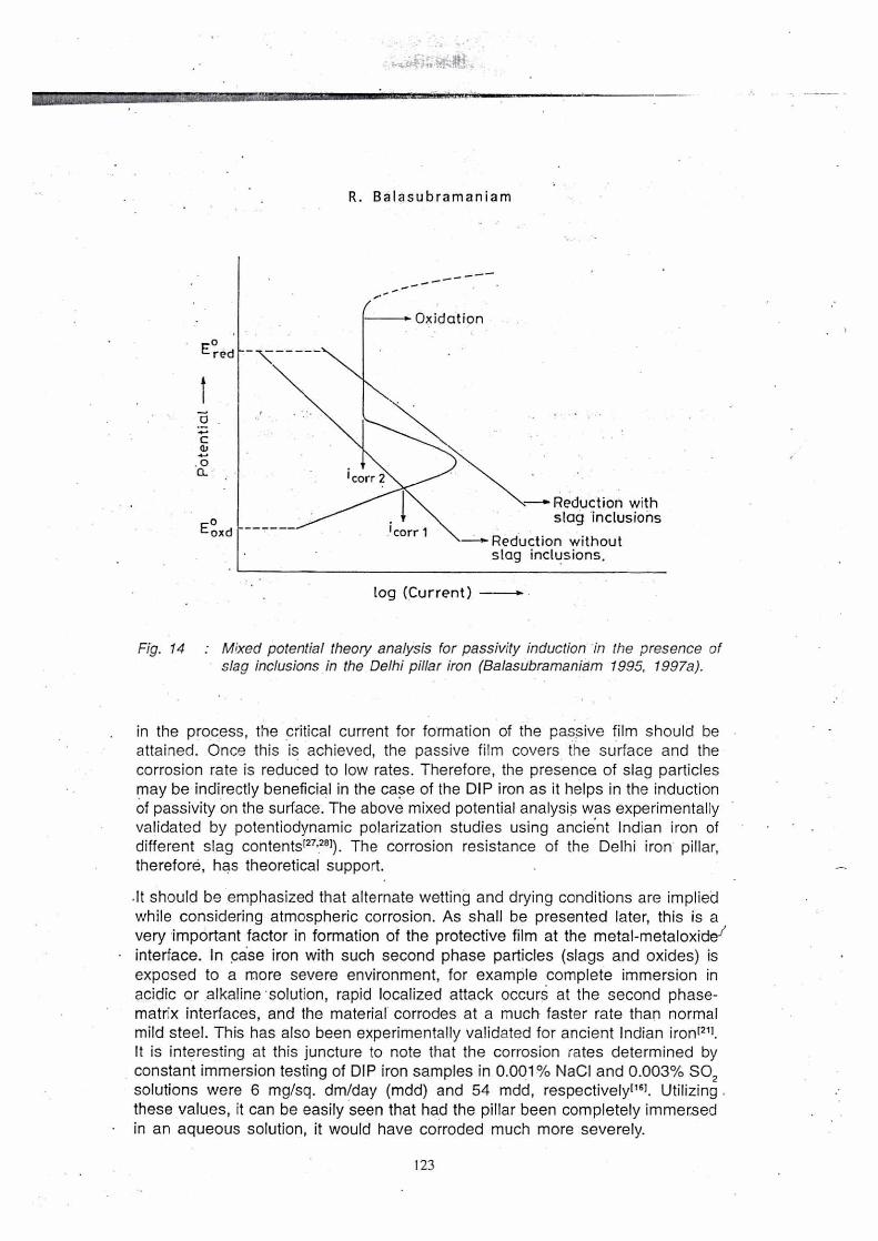
In case the DIP iron did not contain slag particles, the cathodic activation polarization line would have intersected the anodic polarization curve in the—/ active region. This is reasonable as relatively large currents are needed to induce passivity in iron containing P as the critical current density for passivation is relatively large in iron containing P[m. However, in the presence of slag particles, the exchange current of the cathodic reaction(s) would be higher than in the case when there were no slag particles and the cathodic activation polarization line would shift to the right as shown in Fig. 14. Notice that current is depicted in the X-axis and not current density because this representation is useful in elucidating the effect of second phase particles in inducing passivity on the DIP iron. Therefore, .in the presence of second phase particles, the higher current demand of the cathodic reaction(s) will demand a higher corrosion current and
121
New Insights on the Corrosion Resistant Delhi Iron Pillar
Hollow Cylinder
Insert
Insert
Fig. 13 Shrink fitting methodology of the Delhi iron pillar decorative capital. Notice that the decorative bell capital is attached to the pillar main . body by means
. of an insert.
122
Oxidation (
icorr 2
N—' Reduction with slag inclusions
Reduction without slag inclusions,
icorr 1
..=
R. Balasubramaniam
er d
a
Ec)oxd
log (Current)
Fig. 14 : Mixed potential theory analysis for passivity induction in the presence of slag inclusions in the Delhi pillar iron (Balasubramaniam 1995, 1997a).
in the process, the critical current for formation of the passive film should be attained. Once this is achieved, the passive film covers the surface and the corrosion rate is reduced to low rates. Therefore, the presence of slag particles may be indirectly beneficial in the case of the DIP iron as it helps in the induction of passivity on the surface. The above mixed potential analysis was experimentally validated by potentiodynamic polarization studies using ancient Indian iron of different slag contents127,281). The corrosion resistance of the Delhi iron pillar, therefore, has theoretical support.
it should be emphasized that alternate wetting and drying conditions are implied while considering atmospheric corrosion. As shall be presented later, this is a very important factor in formation of the protective film at the metal-metaloxidel interface. In case iron with such second phase particles (slags and oxides) is exposed to a more severe environment, for example complete immersion in acidic or alkaline solution, rapid localized attack occurs at the second phase-matrix interfaces, and the material corrodes at a much faster rate than normal mild steel. This has also been experimentally validated for ancient Indian iron1211. It is interesting at this juncture to note that the corrosion rates determined by constant immersion testing of DIP iron samples in 0.001% NaCI and 0.003% SO2 solutions were 6 mg/sq. dm/day (mdd) and 54 mdd, respectively'161. Utilizing these values, it can be easily seen that had the pillar been completely immersed in an aqueous solution, it would have corroded much more severely.
123

010 80 70 90
• 3000
2500
2000
1500
1000
500
30 40 50• 60 2Thela (degrees)
New Insights on the Corrosion Resistant Delhi Iron Pillar
Delhi Iron Pillar Rust Characterization
The mixed potential theory analysis clearly indicated that the pillar obtains its corrosion resistance due to the formation of a passive film on the surface. This can be gleaned by analyzing the available corrosion rate data. Assuming parabolic growth kinetics, the predicted thickness of the scale was about 200 pm after about 1600 years of growth. The excellent match of the estimated thickness with that experimentally determined by Bardgett and Stannersm, using a permanent-magnet type thickness gauge, is proof that the film that forms on the surface is
protective in nature as it grows according to parabolic kinetics. In order to gain insights on the nature of the passive film, a minute amount of rust sample was characterized by X-ray diffraction (XRD)(31). Fourier ,transform infrared (FTIR) spectroscopyt32] and M6ssbauer spectroscopy[33]... The salient results of the characterization studies are summarized below. It must be emphasized that the rust samples were obtained from the region just below the decorative_ bell capital and therefore, this must be the oldest rust on the pillar as the area from where the rust was collected is inaccessible to the public.
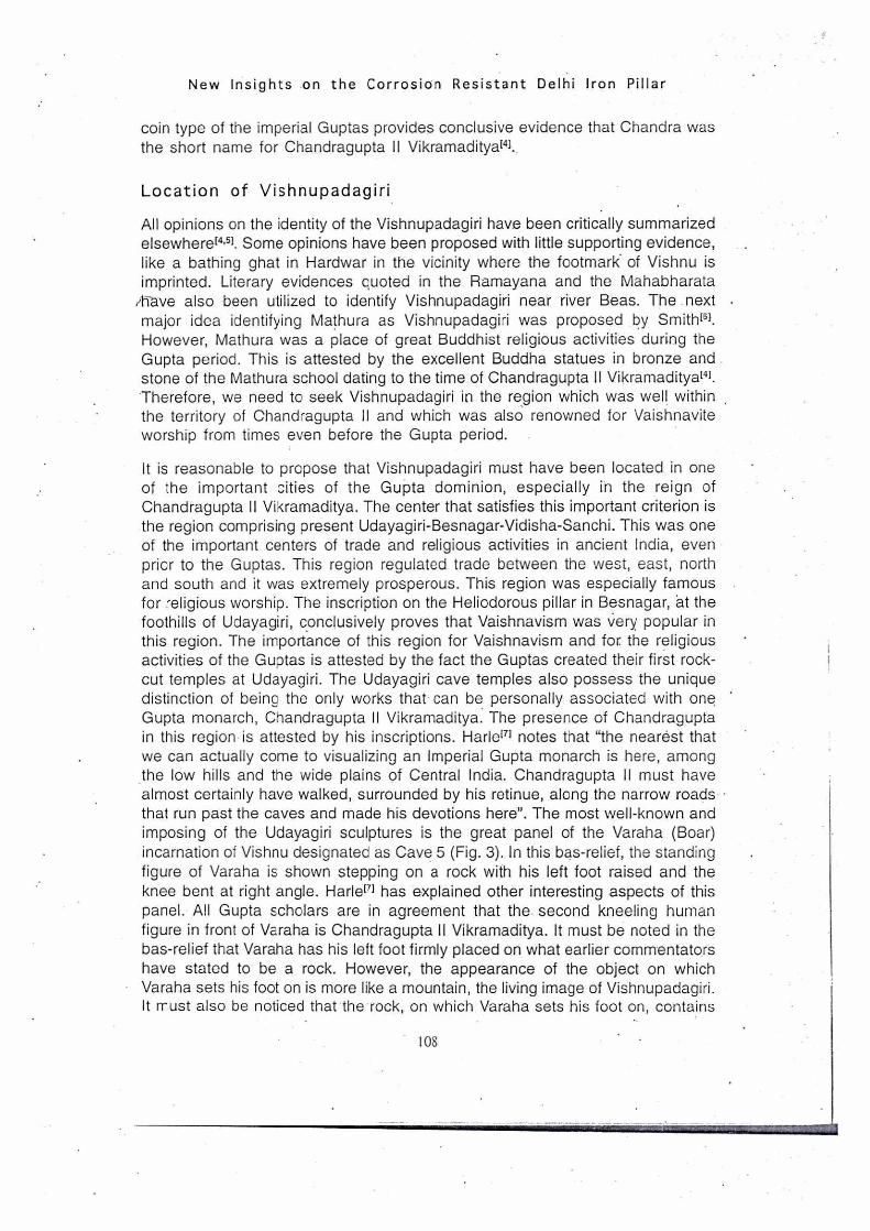
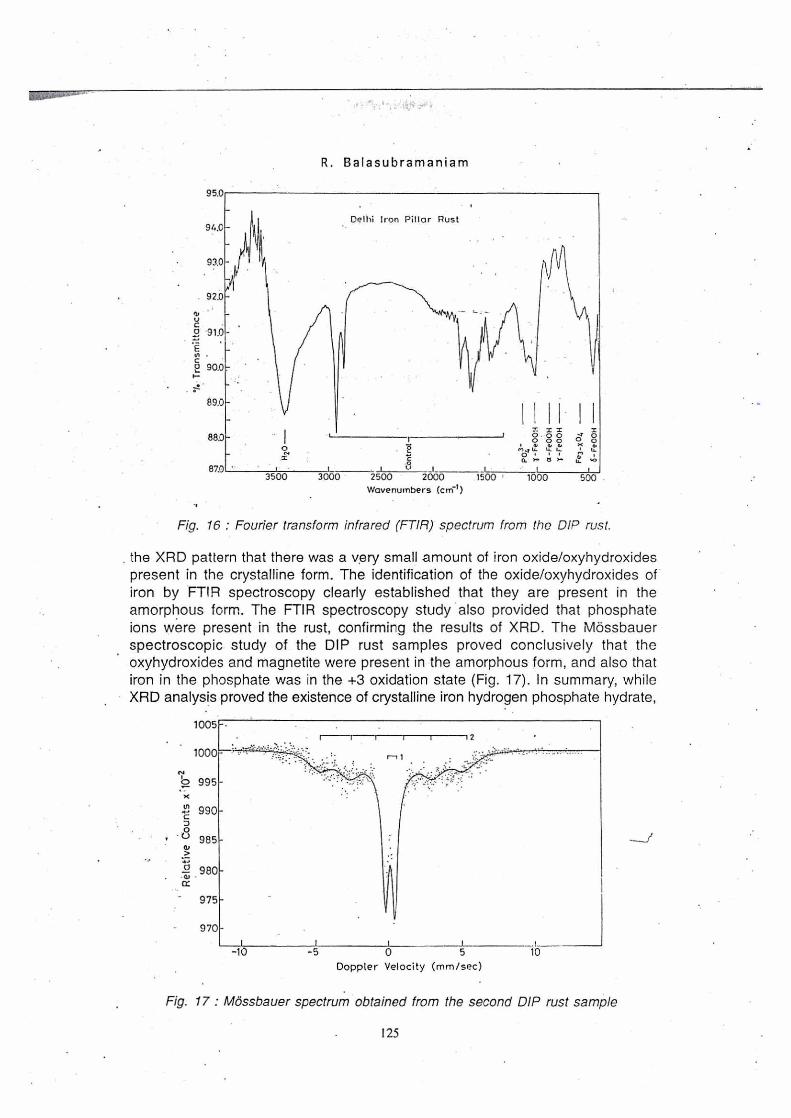
The significant result of the XRD analysis of the DIP rust was tha identification of iron hydrogen phosphate hydrate in the crystalline form (Fig. 15). The FTIR spectroscopy study of the DIP rust clearly established that, in addition .to iron hydrogen phosphate hydrate, the scale also consisted of y-FeOOH (lepidocrocite), a-FeOOH (geothite), 8-Fe00H (misawite), magnetite and phosphates (Fig. 16). The hydrated nature of these products was also indicated. It was also seen in
Fig. 15 : X-ray diffraction pattern of the DIP rust showing the intensities in the region 2q = 10° to 80°.
124
88.0 0
87.0 3500
Delhi Iron Pillar Rust
95.0
96.0
93.0
. 92.0 • 41,
V C • 2 91.0 •
. C (2 90.0
89.0
3000 2500
115
2000 1500 1000 580
7: x 0 • 0 0 v0 0 00 0 0
I rfs ts- 0 s s 0. r.• rs >-• %.■
R. Balasubramaniam
Wavenumbers (cM*1 ) •s
Fig. 16 : Fourier transform infrared (FTIR) spectrum from the DIP rust.
the XRD pattern that there was a very small amount of iron oxide/oxyhydroxides present in the crystalline form. The identification of the oxide/oxyhydroxides of iron by FTIR spectroscopy clearly established that they are present in the amorphous form. The FTIR spectroscopy study also provided that phosphate ions were present in the rust, confirming the results of XRD. The MOssbauer spectroscopic study of the DIP rust samples proved conclusively that the oxyhydroxides and magnetite were present in the amorphous form, and also that iron in the phosphate was in the +3 oxidation state (Fig. 17). In summary, while XRD analysis proved the existence of crystalline iron hydrogen phosphate hydrate,
1005
1 12
1000
b 995
990
0 (—) 985
•980
tt
975
—_/
970
1 1 1 !
-10 -5 0 5 10 Doppler Velocity (mm/sec)
Fig. 17 : Mossbauer spectrum obtained from the second DIP rust sample
125
New Insights on the Corrosion Resistant Delhi Iron Pillar
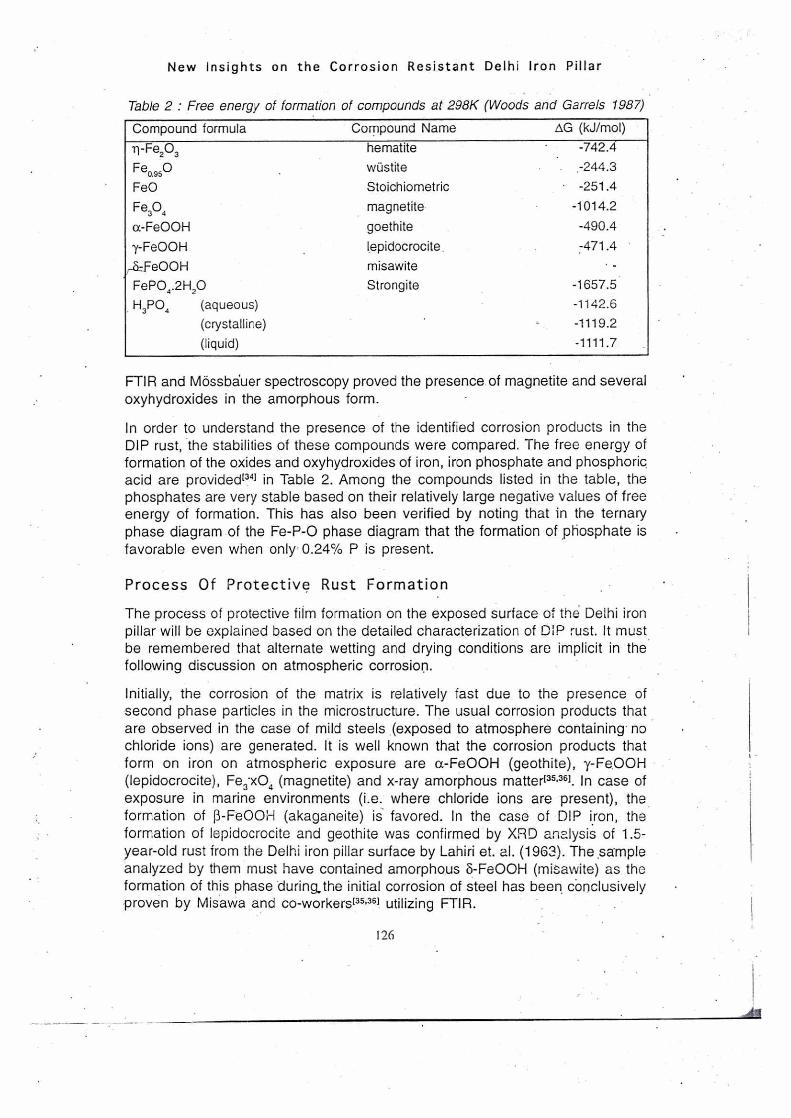
Table 2 : Free energy of formation of compounds at 298K (Woods and Garrels 1987)
Compound formula
Compound Name OG (kJ/mol)
ri-Fe203 hematite -742.4
Fe0.950 wustite .-244.3
FeO Stoichiometric • -251.4
Fe304 magnetite -1014.2
a-FeOOH goethite -490.4
y-FeOOH lepidocrocite . -471.4
,,-ZzFe00H misawite FePO4.2H20 Strongite -1657.5 H3PO4 (aqueous) -1142.6
(crystalline) -1119.2
(liquid) -1111.7
FTIR and MOssbuer spectroscopy proved the presence of magnetite and several oxyhydroxides in the amorphous form.
In order to understand the presence of the identified corrosion products in the DIP rust, the stabilities of these compounds were compared. The free energy of formation of the oxides and oxyhydroxides of iron, iron phosphate and phosphoric acid are provided[341 in Table 2. Among the compounds listed in the table, the phosphates are very stable based on their relatively large negative values of free energy of formation. This has also been verified by noting that in the ternary phase diagram of the Fe-P-0 phase diagram that the formation of phosphate is favorable even when only 0.24% P is present.
Process Of Protective Rust Formation
The process of protective film formation on the exposed surface of the Delhi iron pillar will be explained based on the detailed characterization of DIP rust. It must be remembered that alternate wetting and drying conditions are implicit in the following discussion on atmospheric corrosion.
Initially, the corrosion of the matrix is relatively fast due to the presence of second phase particles in the microstructure. The usual corrosion products that are observed in the case of mild steels (exposed to atmosphere containing no chloride ions) are generated. It is well known that the corrosion products that form on iron on atmospheric exposure are a-FeOOH (geothite), y-Fe.00H (lepidocrocite), Fe3-x04 (magnetite) and x-ray amorphous matter[35,361. In case of exposure in marine environments (i.e. where chloride ions are present), the formation of r3-Fe001-1 (akaganeite) is favored. In the case of DIP iron, the formation of lepidocrocite and geothite was confirmed by XRD analysis of 1.5-year-old rust from the Delhi iron pillar surface by Lahiri et. al. (1963). The sample analyzed by them must have contained amorphous 8-Fe0OH (mi8awite) as the formation of this phase during, the initial corrosion of steel has been conclusively proven by Misawa and co-workers[35,361 utilizing FTIR.
126
A!
otioitioa,„
R. Balasubramaniam •
The initial.enhanced corrosion of the matrix leads to, the,enrichment of P concentration• at.the.rnetal-scale interface. In the presence of P at the interface between the metal and rust, the formation of a compact layer of amorphous 5- Fe0OH layer next to the metal-metaloxide interface should be favored like that observed in the case of P-containing weathering steels. The formation of amorphous 6-FeCOH confers the initial corrosion resistance to the DIP iron. The 6-FeOOH phase forms in a discontinuous manner in normal mild steels while it forms as a compact layer next to the metal-metaloxide interface in the case of P- or Cu-containing weathering steels due to catalytic. action133xl. The superior corrosion resistance of P- and Cu-containing weathering:steels has been attributed to this compact.5-Fe0OH layer next to the metal surface, which is -also. enriched with the element(s) added to provide weathering resistance' Cu and P). This mechanism may not _apply to Cr-containing weathering steels1371.
It is important to note that the oxyhydroxides and magnetite present in the old DIP rust are nanocyrstalline/amorphous in nature and not crystalline. As it is known that the initial oxide and oxyhydroxides that form on the DIP iron are crystalline in nature[m, the longterm conversion of the crystalline forms of these oxyhydroxides to the amorphous form is indicated. The crystalline oxide/ oxyhydroxides of iron are converted to the amorphous state due to process of alternate wetting and drying, as has been shown. in P-containing weathering steelr351. •
The enrichment of P in the 5-Fe0OH layer continues with .prolonged exposure and this has been observed in P-containing weathering steels[35,361. This enrichment should be responsible for the precipitation of the insoluble phosphate identified by XRD. The process of formation of crystalline iron hydrogen phosphate hydrate would be understood based on the vast literature available on phosphating of steels[381. This exercise would also be useful in further understanding the reason for the Delhi iron pillar's excellent corrosion resistance.
Phosphating of iron is a commercially important coating method, which involves the formation of relatively insoluble, electrically. non-conducting thin films of metallic phosphates on the surface. It is known that the formation of a protective layer on Fe surface involves the following four steps[38). In the first step, electrochemical attack of iron by orthophosphoric acid occurs over a wide range of concentration and temperature. In the case of DIP iron, the formation of orthophosphoric acid next to the metal surface has to be first understood.
The enrichment of P at this location was earlier established due to the initial corrosion of matrix. However, it is also important to also note that the concentration of P is relatively higher near the surface regions of the DIP iron than in the bulki161. It was earlier noted that the surface regions of DIP contain a higher amount of ferrite (i.e. depleted of carbon) which is due to the final surface finishing operafion provided to the pillar during its manufacture. It is known that P diffuses and concentrates in regions where C is depleted and therefore, concentration of P is relatively higher near the surface regions of the pillar. Therefore, enrichment of P. in the 5-Fe0OH layer is expected.
127

New Insights on the Corrosion Resistant Delhi Iron Pillar
This P enrichment has been experimentally determined by Ghosh[161 who mentioned that the P content in the DIP rust was 0.35% whereas the P content in the DIP iron was 0.18%. The enrichment of P in the rust would initially result in the formation of phosphoric acid at the metal-metaloxide interface due to the presence of P at this location and also as free energy consideration favor its formation. The moisture for phosphoric acid formation obtains in the alternate wetting and drying cycles. In contact with phosphoric acid, the dissolution potential of iron becomes less noble and it causes the dissolution of Fe to sparingly soluble dihydrogen phosphate according to
2H3PO4 + Fe ---> Fe(H2PO4)2 + H2
The transient oxides of iron (in which Fe is in the +2 oxidation state) will also be corroded by phosphoric acid to provide Fe(H2PO4)2 according to •
2H3PO4 + Fe0 --> Fe(H2PO4)2 + H2O
Among the above two reactions, the first one mainly occursmi. In the second stage, the contact of the metal shifts the equilibrium in such a way that massive precipitation of monohydrogen phosphate FeHPO4 and tribasic iron phosphate Fe3(PO4)2 occurs. The precipitation reactions are
3Fe(H2PO4)2 ---> Fe3(PO4)2 + 4H3PO4
Fe(H2PO4)2 —> FeHPO4 + H3PO4
The interesting to notice that iron is in the +2 oxidation state in these phosphates. Both these phosphates are insoluble in nature. Moreover, these phosphates are also amorphous in nature and this is well corroborated by experimental evidence. In normal phosphating processes, the phosphating reactions generally discussed are up to the sequence of events provided above. In normal practice, other cations such as Zn or Mn are also added to phosphoric acid. In some cases, oxidizing agents are. added so that iron may appear in the coating as ferric phosphate. This has been proved to be more beneficial to corrosion resistance as the crystal reorganization of the amorphous phosphates to ferric phosphates results in a large reduction in the porosity of the phosphate and subsequently, much improved protective properties.
The oxidation of iron to ferric phosphate can also be achieved by alternate wetting and drying cycles. The H2PO4- ions accelerate the air oxidation of Fe2+ to Fe3+ under alternate wetting and drying cycles and also prevent the crystal growth of the corrosion products. Over time, Fe3(PO4)2 is oxidized by atmospheric oxygen and H3PO4 to iron hydrogen phosphate hydrate according to:
2Fe3(PO4)2 + 8H3PO4 + (3/2) 02 + 2H20 =
6 (FePO4.H3PO4.4H20)
128
R. Balasubramaniam
In this cornpound, iron is in the -1.-3 State and this can be understood if one considers the-'ab6Ve reaction in parts as follows:
2Fe3(PO4)2 2H3PO4 + (3/2) 02 + 91-120 = 6 (PePO;i:2H20)
FePO4.2H20 + H3PO4 + 2H20 = FePO4.H3PO4.4H20
The dissolUtion and reprecipitation reaction also leads to a change in the pH of the metal-solution interface, which leads to a 'crystalline reorganization and followed, most importantly, by a large decrease in porosity. The crystalline reorganization is a very deep-seated reaction (at the metal-phosphate interface) because it modifies the porosity of the passive layer and decreases markedly the exposed metallic surface["1. Therefore, the formation of the_ crystalline modification of iron hydrogen phosphate hydrate from the amorphous phosphate is critical in providing excellent protection against further ingress of moisture and oxygen to the metal surface. .
The continuous layer of crystalline iron hydrogen phosphate hydrate (formed at the metal-metaroXide- interface) is, therefore, responsible for.the superior corrosion resistance of the Delhi iron pillar. Ghosh[1,61 anticipated, this mechanism in his excellent study of the. DIP iron. He stated that "P accumulate's in a new phase at the base of the main oxide layer in the oxide form in combination with iron" and "so long as the new phase at the base of the main oxide film was not formed, the metal behaviour was similar to that of exposure surface of ordinary irons". Ghosh[161 performed some simple experiments with the DIP iron piece to assess the influence of P on rusting. The sample was polished. and allowed to rust. When a thin and unequally distributed film of rust was formed, it was photographed and slightly polished to remove the rust from the surface. This surface' was treated with Stead's solution to observe the distribution of P on the surface. In was found that P was 'generally low in the areas where rust appeared more intensely..
Alternate wetting and drying conditions play an important role in the case of atmospheric Corrosion of the DIP because these conditions accelerate the precipitation of.protective crystalline phosphate and the amorphization of the DIP rust. The amorphization of rust is also aided by the presence of H2PO4- ions. The iron pillar's weight is estimated to be approximately 6 tons and therefore, the large mass of the metal plays a contributory role in aiding the alternate wetting and drying process. Sanyal and Prestont3. ] and, later, Bardgett and Stannersmi proposed that the large mass of the pillar implies a large heat capacity for the iron and therefore, the pillar will heat up faster or cool down faster than the surroundings. This provides the right conditions of alternate wetting and drying of the iron pillar -surface. The intensity of wetting and subsequent drying would be much more in the case of DIP iron because of the large mass of the pillar. In summary,' the phoSphate film theory originally presented by Ghosh[161 and elaborated in detail laterr27'281 is valid, with the minor difference being that it is the crystalline (and not amorphous as originally proposed by Balasubramaniam) iron. hydrogen phosphate hydrate layer that is responsible for the corrosion resistance
129
New Insights on the Corrosion Resistant Delhi Iron Pillar
of the Delhi iron pillar. The conclusion drawn in unambiguous as it has strong experimental support from actual Delhi iron pillar rust characterization.
Difference With Corrosion of Steel and Weathering Steels
The protective passive film that form on the DIP would be contrasted with the films forming on mild and weathering steel on atmospheric exposure. Structure-related issues of the rusts are discussed as the compositional factors have already been outlined earlier. The rusting of normal mild steel and weathering
•steel is first addressed. When iron is exposed to the environment, the first oxides that form are the oxyhydroxides of Fe which are oxidized from Fe(II) complexes(351. Although several different allotropic modifications of the oxyhydroxides have been proposed to form on the surface of iron on initial exposure to the environment, there are firm evidences in the literature to suggest and prove that the first oxyhydroxide to form is -y-Fe00H. After this forms, a part of it begins to transform to another allotropic modification (a-FeOOH) and the rust at later times is composed of both these oxyhydroxides. Both these oxyhydroxides are not protective against corrosion and they readily crack allowing for ingress of oxygen and moisture to reach the metal surface and cause further corrosion.
However, with time, a part of the FeOOH formed transforms to magnetic oxides of iron, which are much more protective than these oxyhydroxides. There is also debate on the exact nature of the magnetic oxide that form on exposure of the iron to the environment. This is because. the diffraction peaks of Fe304 and y, Fe203 occur at the same location. However, Mossbauer studies of rust formed on steel exposed to the environment does indicate that Fe304 (more precisely to be called Fe3-x04) forms first and this is later converted to y-Fe203. The formation of this magnetic oxide results in protection and the oxidation (corrosiori) rates decrease once these oxides form on the surface from the oxyhydroxides. In addition to a- and y-Fe0OH, there can be another oxyhydroxide of nature 5- Fe0OH, which can form on atmospheric exposure of iron.
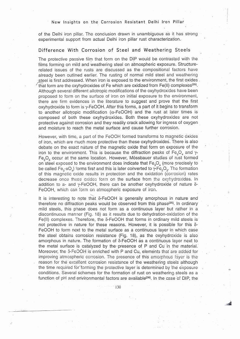
It is interesting to note that 5-Fe0OH is generally amorphous in nature and therefore no diffraction peaks would be observed from this phase[351. In ordinary mild steels, this phase does not form as a continuous layer but rather in a discontinuous manner (Fig. 18) as it results due to dehydration-oxidation of the Fe(II) complexes. Therefore, the 5-Fe0OH that forms in ordinary mild steels is not protective in nature for these reasons. However, it is possible for this 5- Fe0OH to form next to the metal surface as a continuous layer in which case the steel obtains corrosion resistance (Fig. 18),
as the oxyhydroxide is also
amorphous in nature. The formation of 8-.Fe00H as a continuous layer next to the metal surface is catalyzed by the-presence of P and Cu in the material. Moreover, the 5-Fe0OF.1 is enriched with P and Cu, elements that are added for improving atmospheric corrosion. The presence of this amorphous Iyer is the reason for the excellent corrosion resistance of the weathering steels although the time required forforMing the protective layer is determined by the exposure conditions. Several schemes for the formation of rust on weathering steels as a function of pH and environmental factors are available1361. In the case Of DIP, the
130

MILD STEEL
Cracks
Metal //////
ci.- Fe0OH • )4- Fe0OH • •
• am...ft. • • .
•
•MO
Fe 3 04
Amorphous 8 - Fe0OH layer
'iron hydrogen phosphate hydrate
(Fe PO4 • H3 PO4 4 H20)
1.
42
• :;
R. Balasubramaniam
WEATHERING STEEL
(1- Fe0OH • • - Fe0OH • . • . • • • •
• • '• • • , - • Fe3_x 04 .• , . .
• -7-47:i.. . • • •
Amorphous 6- Fe0OH layer ) enrichment mimes- - •
-777777 7"--- 7:77 777777 -7 Metal- .(Cu,Cr, P)
Cu, Cr, Ni. P
' DELHI IRON PILLAR
Fig. 18.: ScheMptic comparing the rust structure formed on mild steel, weathering steel and Delhi Iron pillar
process of protective rust formation has been outlined in great detail earlier. The structure of the passive film on the DIP is schematically. provided in Fig. 18 for comparison with the films that form on mild and weathering steels. Cross sectional microstructural analysis of DIP rust confirms the structure of DIP rust presented'29].
CONCLUSIONS
Several new insights on the Delhi iron pillar have been presented in this communication. Numismatic evidences have been provided to firmly conclude that Chandra, mentioned in the oldest Sanskrit inscription, should be identified with Chandragupta II Vikramaditya. Udayagiri has been identified as the original location of the pillar, i.e. the Vishnupadagiri mentioned in the inscription. The engineering design and the manufacturing methodology of the pillar have been discussed. The corrosion resistance of the pillar has been addressed in great detail. The nature of the protective passive layer on the corrosion resistant Delhi iron pillar (DIP) has been elucidated based on a detailed characterization of its rust. The rust was composed of iron hydrogen phosphate hydrate (FePO4.H3PO4. 4H20) in the crystalline form in addition to a-, 7-, 5-Fe0OH and magnetite, all in amorphous form. The process of protective rust formation on DIP iron has been outlined based on the rust analysis. The passive film formation on the Delhi iron
131

New Insights on the Corrosion Resistant Delhi Iron Pillar
pillar has been contrasted with rusting of normal and weathering steels. The critical factor aiding the superior corrosion resistance of the Delhi iron pillar is the formation of crystalline iron hydrogen phosphate hydrate, as a thin layer next the metal-metaloxide interface, which drastically lowers the rate of corrosion due to its low porosity content. The process of protective crystalline phosphate formation is aided by alternate wetting and drying cycles, which is the important contribution of the atmosphere to the DIP's corrosion resistance. Therefore, the corrosion resistance of the Delhi iron pillar is due to both Delhi (with the environment providing alternate wetting and drying conditions) and iron (with its high P content e.onferring protection by the formation of the crystalline iron hydrogen phosphate).
REFERENCES
1. Hadfield, R., 1912. Sinhalese Iron and Steel of Ancient Origin, J. Iron Steel Inst., 85, pp. 134-174
2. Wranglen, G.,1970. The Rustless Iron Pillar at Delhi, Corrosion Sc., 10, pp. 761-770. •
3. Anantharamgn, T.R., 1997. The Rustless Wonder - A Study of the Delhi Iron Pillar, New Delhi, Vigyan Prasar.
4. Balasubrarnaniam, R., 2000a. Identity of Chandra and Vishnuoadagiri of the Delhi Iron Pillar Inscription: Numismatic, Archaeological and Literary Evidences, Bull. Metals Museum, 32, pp. 42-64.
5. Balasubramaniam, R., 1997b. New Insights on the Corrosion of the Delhi Iron Pillar based on Historical and Dimensional Analysis, Current Sc., 73, pp. 1057-67
6. Smith, V.A., 1897. The Iron Pillar at Delhi, J. of the Royal Asiatic Society of Great Britain and Ireland, pp. 1-18
.7. Harle, J.C., 1974. Gupta Sculpture: Indian Sculpture of the Fourth to the Sixth Centuries AD, Oxford, Clarendon Press.
8. Beglar, Y.D., 1871/72. Archaeological Survey of India Annual Reports, 1871/72, IV, pp. 28-30.
9. Nath, R., 1984. Monuments of Delhi - Historical Study, The Histor;cal Research Documentation Center Programme, Jaipur, Illustration 18.
10. Cole, H.H., 1872. The Architecture of Anaient Delhi, Especially the Buildings around the Kutb Minar, London, plate I.
11. von Schwarz, C.R., 1901. Ueber die Eisen- and Stahlindustrie Ostindiens", Stahl and Eisen, 21, pp. 209-211 and 277-283
12. Balasubramaniam, R., 1998a. The Decorative Bell Capital of the Delhi Iron. Pillar, JOM, 50;3), pp. 40-47..
13. Balasubramaniam, R., 1998b. On the Presence of Lead in the Da!hi Iron Pillar, Bull. Metals Museum, pp. 29-I, 19-39.
14. Balasubramaniam, R., 1999b. Some Aspects of Lead Presence in the Delhi Iron Pillar, Current Science, 77, pp. 681-686.
15. Balasubramaniam, R., 1999a. Elucidation of Manufacturing Methodology Employed to Construct the Main Body of the Delhi Iron Pillar, Bull. Metals Museum, 31, pp. 40-63.
16: Ghosh, M.K., 1963. The Delhi Iron Pillar and Its Iron, NML Technical J., 5, pp. 31-45. • 17. Lahiri, A.K., Banerjee, T and Nijhawan, B.R., 1963. Some Observations on Corrosion
Resistance of Ancient Delhi Iron Pillar and Present-time Adivasi Iron Made by Primitive Methods, NML Tech. J., 5, pp. 46-54.
132
R. Balasubramaniam . ••
18. Lal, 13:13., 1996. in The Delhi Iron Pillar: Its Art, Metallurgy and Inscriptions, eds. S.K. Gupta and Shankar Goya!, Jodhpur, Kusumanjali Book World, pp
22-58.
19. Bardgett, W.E and Stanners, J.F., 1963. The Delhi Iron Pillar - A Study of the Corrosion Aspects, J. Iron and Steel Inst., 210, 3-10 & NML Technical J., 5, pp. 24-30.
20. Prakash, B., 1991. Metallurgy of Iron and Steel Making and Blacksmithy in Ancient India, Ind. J.. Hist. Sci., 261, pp. 351-371.
21. Puri, V., Balasubramaniam, R and Ramesh Kumar, A.V., 1997. Corrosion Behaviour of Ancient 150.0,year old Gupta Iron, Bull. Metals Museum,, pp. 28-11, 1-10.
22. Ramesh- Kumar,-A.V and Balasubramaniam, R., 1998.. Corrosion Product Analysis of Ancient Corrosion Resistant Indian Iron, Corrosion Science, 40, pp. 1169-1178.
23. Evans; 1926. Corrosion of Metals, London, Edward Arnold, p. 266.
24. Moore, 1990. Slag Chemistry, in Chemical Metallurgy, Second Edition, Chapter 5, Oxford; Butterworth-Heinemann, pp. 152-192.
25. Balasubramaniam, R., 2000b. On the Origin of High P Contents in Ancient Indian Irons, to be published.
26. Buchanan, F.A., 1807. Journey from Madras Through the Countries of Mysore, Canara and Malabar, East India Company, London.
27. Balasubramaniam, R., 1995. Studies on the Corrosion Resistance of the Delhi Iron Pillar, NML Technical J., 37, pp.123-145.
28. Balasubramaniam, R., 1997a. Mixed Potential Theory Analysis of the Corrosion Resistance of the Delhi Iron Pillar, Trans. Indian. Inst. Metals; 50, pp. 23-35.
• 29. Balasubramaniam; R., 2000c. On the Corrosion Resistance of the Delhi Iron Pillar, Corrosion Science, accepted.
30. Chance, R.L and France, Jr., W.D.,-1969. Anodic Polarization Characteristics of Phosphated Steels, Corrosion, 25, pp. 329-335.
31. Balasubramaniam, R., 2000d. X-Ray Diffraction Analysis of Delhi Iron Pillar Rust, NML Tech. J., communicated.
32. Ramesh KOmar, A.V and Balasubramaniam, R., 2000a. Fourier Transform Infrared Spectroscopic Analysis of Delhi Iron Pillar Rust, NML Tech. J., communicated.
. 33. Ramesh Kumar, A.V and Balasubramaniam, R., 2000b. Mossbauer Spectroscopic Analysis of Delhi Iron Pillar Rust, NML Tech. J., communicated.
34. Wood, T.L and Garrels, R.M., 1987. Thermodynamic Values at Low Temperature for Natural Inorganic Materials: A Critical Summary, Oxford, Oxford University Press, 'pp. 100-106.
35. Misawa, T., et al., 1971. The Mechanism of Atmospheric Rusting and the Effect of Cu, and P on the Rust Formation of Low Alloy Steels, Corrosion Science, 11, pp. 35-48.
36. Misawa, T., et al., 1974. The Mechanism of Atmospheric Rusting and the Protective Rust on Low Alloy Steel, Corrosion Science, 14, pp. 279-289.
37. Yamashita., et al., 1994. The Long Term Growth of the Protective Rust Layer Formed ;:m Veathering Steel by Atmospheric Corrosion During a Quarter of a Century"; Corrosion Science, 36, pp. 283-299. ,•.,
38. Ghali, E.L: and. potoin, R.J.A., 1972. The Mechanism of Phosphating of Steel, CorroSior(Sdiehce, 12, pp. 583-594.
39. Sanyal, B and Preston, R., 1952. Note on Delhi Pillar, Chemical Research Laboratory, London.
133