New-Generation, Low-Temperature Lead-Free Solder …...based on IPC J-STD-005A. These powders were...
7
New-Generation, Low-Temperature Lead-Free Solder for SMT Assembly Boon-Ho Lee, Chun-Yu Chang, Chih-Hsiang Li, Kuo-Shu Lin, Shih-Lo Yueh, Seiji Kobayashi SHENMAO Technology Inc. Hsinchu County, Taiwan [email protected] Watson Tseng SHENMAO America, Inc. San Jose, CA, USA [email protected] Abstract Sn3Ag0.5Cu (SAC305) is the major solder alloy after RoHS was adopted by the European Union. Since its melting temperature is relatively higher than eutectic SnPb alloy, the peak reflow temperature increases. This transformation in the assembly industry impacts the component requirement, where the deformation probability (warpage) of a flat component is increased, which impacts the production yield. A lead-free, low-temperature SMT solder is needed to resolve this dilemma. Low-temperature SMT assembly refers to the reflow process with a peak temperature less than 200°C. The new process provides a few advantages like reducing energy consumption, reducing BGA component warpage during reflow and diminishing non-wetting open (NWO) and head-on-pillow (HoP) defects. The SnBi alloy is one of the candidates used in low-temperature SMT assembly. However, the brittle mechanical property of conventional SnBi alloys will degrade the reliability of the assembly. The SnBi alloy properties can be altered via several means. In this paper, the roles of additive and bismuth content will be discussed. Eutectic SnBi and three newly designed SnBi-based alloys (Sn57Bi1AgX, Sn48Bi1AgX and Sn40Bi1AgX, X represents <0.5wt.% of additive element) were experimented upon. Solder pastes that were blended with the aforementioned alloys and flux were used to assemble on the PCB with BGA components that have SAC305 solder spheres pre-mounted. The same reflow profile was used for all pastes. Cross-sectional analysis, shear testing, drop testing and thermal cycling testing were conducted to determine the microstructure, shear force, drop reliability and thermal reliability. The results show that the microstructure, especially the bismuth-rich phase, became finer and the shear force was elevated when the additive was added. On the other hand, the drop reliability improved with decreasing bismuth content, and the thermal reliability improved with increasing bismuth content. Introduction Low-Temperature Solder (LTS) refers to a solder alloy with liquidus below eutectic Sn37Pb (183˚C). The common LTS is eutectic Sn58Bi alloy, with a melting point of 139˚C [1,2] . For the SMT process, the peak reflow temperature of the LTS paste should be below 200˚C. The main driving force for the LTS transition is increasing demand for ultra-thin packages. Reduction in package thickness increases its warpage, and this warpage generates production yield loss [3] .Also, the reflow temperature of SnAgCu series solder paste is much higher than the glass transition temperature (Tg) of the substrate. This is another factor increasing substrate and PCB warpage. LTS paste can reduce the reflow temperature to below 200˚C, hence decreasing both PCB and substrate deformation. LTS Benefits and Drawbacks LTS provides numerous benefits. The four most notable are listed below. Improved production yield The reflow temperature of LTS is lower than SAC305. As a result, the deformation of PCBs and substrates is relatively small, and it subsequently improves the packaging yield of BGA components. Reduced thermal stability requirement of PCBs and components Because the reflow temperature is decreased, PCBs and components no longer need to withstand 240~250°C. Additionally, the product designer can choose components and PCBs with low thermal stability, thereby reducing product cost (Figure 1). As originally published in the SMTA Proceedings
Transcript of New-Generation, Low-Temperature Lead-Free Solder …...based on IPC J-STD-005A. These powders were...

New-Generation, Low-Temperature Lead-Free Solder for SMT Assembly
Boon-Ho Lee, Chun-Yu Chang, Chih-Hsiang Li, Kuo-Shu Lin, Shih-Lo Yueh, Seiji Kobayashi
SHENMAO Technology Inc.
Hsinchu County, Taiwan
Watson Tseng
SHENMAO America, Inc.
San Jose, CA, USA
Abstract
Sn3Ag0.5Cu (SAC305) is the major solder alloy after RoHS was adopted by the European Union. Since its melting
temperature is relatively higher than eutectic SnPb alloy, the peak reflow temperature increases. This transformation in the
assembly industry impacts the component requirement, where the deformation probability (warpage) of a flat component is
increased, which impacts the production yield. A lead-free, low-temperature SMT solder is needed to resolve this dilemma.
Low-temperature SMT assembly refers to the reflow process with a peak temperature less than 200°C. The new process
provides a few advantages like reducing energy consumption, reducing BGA component warpage during reflow and
diminishing non-wetting open (NWO) and head-on-pillow (HoP) defects. The SnBi alloy is one of the candidates used in
low-temperature SMT assembly. However, the brittle mechanical property of conventional SnBi alloys will degrade the
reliability of the assembly. The SnBi alloy properties can be altered via several means.
In this paper, the roles of additive and bismuth content will be discussed. Eutectic SnBi and three newly designed SnBi-based
alloys (Sn57Bi1AgX, Sn48Bi1AgX and Sn40Bi1AgX, X represents <0.5wt.% of additive element) were experimented upon.
Solder pastes that were blended with the aforementioned alloys and flux were used to assemble on the PCB with BGA
components that have SAC305 solder spheres pre-mounted. The same reflow profile was used for all pastes. Cross-sectional
analysis, shear testing, drop testing and thermal cycling testing were conducted to determine the microstructure, shear force,
drop reliability and thermal reliability. The results show that the microstructure, especially the bismuth-rich phase, became
finer and the shear force was elevated when the additive was added. On the other hand, the drop reliability improved with
decreasing bismuth content, and the thermal reliability improved with increasing bismuth content.
Introduction
Low-Temperature Solder (LTS) refers to a solder alloy with liquidus below eutectic Sn37Pb (183˚C). The common LTS is
eutectic Sn58Bi alloy, with a melting point of 139˚C[1,2]. For the SMT process, the peak reflow temperature of the LTS paste
should be below 200˚C.
The main driving force for the LTS transition is increasing demand for ultra-thin packages. Reduction in package thickness
increases its warpage, and this warpage generates production yield loss[3].Also, the reflow temperature of SnAgCu series
solder paste is much higher than the glass transition temperature (Tg) of the substrate. This is another factor increasing
substrate and PCB warpage. LTS paste can reduce the reflow temperature to below 200˚C, hence decreasing both PCB and
substrate deformation.
LTS Benefits and Drawbacks
LTS provides numerous benefits. The four most notable are listed below.
Improved production yield
The reflow temperature of LTS is lower than SAC305. As a result, the deformation of PCBs and substrates is relatively
small, and it subsequently improves the packaging yield of BGA components.
Reduced thermal stability requirement of PCBs and components
Because the reflow temperature is decreased, PCBs and components no longer need to withstand 240~250°C. Additionally,
the product designer can choose components and PCBs with low thermal stability, thereby reducing product cost (Figure 1).
As originally published in the SMTA Proceedings

0
50
100
150
200
250
0 50 100 150 200 250 300 350
ReflowTemp.
[°C]
Reflow Time [sec]
SAC Tm
LTS Tm
SAC Reflow
LTS Reflow
Figure 1. Benefits of using LTS assembly
Energy conservation
Since the reflow temperature is decreased, the reflow oven’s energy consumption also is reduced. However, the actual benefit
is related to the thermal storage ability of the oven, product type, production quantity, etc.
Green production
The green issue becomes critical in electronics production as can be seen in Figure 2. Because the energy consumption of the
LTS process is decreased, the carbon footprint can be reduced as well.
0
50
100
150
200
250
0 50 100 150 200 250 300 350
ReflowTemp.
[°C]
Reflow Time [sec]
LTSProfile
SAC305Profile
Figure 2. A benefit of LTS is that its reduced energy consumption results in a smaller carbon footprint.
However, the SnBi alloy, especially the Bi-rich phase within its microstructure, is prone to brittle fractures under high strain
rate. In general, the ductility of the SnBi alloy is worse than the SnAgCu alloy. Therefore, the SnBi solder joints show worse
performance in drop test and mechanical shock test.
Ductility Improving Method
The addition of elements as shown in Figure 3 can improve the ductility of SnBi solder by modifying its microstructure:
Additive elements form new phases or react with the Sn matrix to form intermetallic compounds (IMC)
Additive elements to SnBi solder can suppress the coarsening of Bi-rich phase
Intermetallic
Grain Size RefinementDispersion Strengthening
Figure 3. Adding elements can help improve the ductility of SnBi solder by forming IMCs and suppressing the
coarsening of the Bi-rich phase.
Experimental Procedure
Four types of SnBi alloys were investigated in this study: eutectic Sn58Bi and three newly designed SnBi-based alloys
(Sn57Bi1AgX, Sn48Bi1AgX and Sn40Bi1AgX). Each of the solders was tested using the following experiments:

DSC
The differential scanning calorimetry (DSC) measurement was conducted at a heating rate of 10˚C/min from 50˚C-250˚C.
Onset temperature of melting is defined as solidus in this study. The DSC measurement results clarified the solidus as well as
the endset temperature of melting of eutectic Sn58Bi and the three newly designed SnBi-based alloys.
Microstructures
Eutectic Sn58Bi and the three newly designed SnBi-based alloy specimens were cross-sectioned, ground with SiC paper, and
polished with 0.1 μm diamond paste. The microstructure was observed via scanning electron microscopy (SEM), and
chemical compositions were analyzed using an energy-dispersive X-ray spectrometer (EDX) installed in the SEM. An
operating voltage of 20 KeV was used to characterize the microstructures and phases formed in these specimens.
Tensile Properties
Tensile tests were conducted using production tensile tester equipment. Flat samples were prepared per ASTM E8, as shown
in Figure 4. These tests were performed at a constant strain rate of 6 mm/min, stress-strain curves of five samples of each
alloys were recorded at room temperature. The average of the yield strength and elongation were reported in this study.
10mm
100mm
30mm
6mm
30mm32mm4mm
R=6mm
Figure 4. Tensile test sample
SAC Ball/SnBi Paste Hybrid Joint Shear Test
The eutectic Sn58Bi and the three newly designed SnBi-based solder powders were manufactured. Powder size is type 4
based on IPC J-STD-005A. These powders were blended with a zero halogen flux to make solder paste. The SAC305 solder
spheres used in this study had a diameter of 0.45 mm. The board pad finish was Cu-OSP with a 0.4 mm diameter, solder
mask-defined type opening. The eutectic Sn58Bi and the three newly designed SnBi-based solder pastes were printed onto
the board pads using a 100 μm-thick stainless-steel stencil. The SAC305 solder spheres were placed onto the printed solder
paste. SAC solder balls were hybrid bonded with LTS paste to the PCB in a 12-zone reflow oven with the following profile:
preheat between 100~120°C for 120 seconds, peak reflow temperature was 190°C, and time above liquidus was 100 seconds.
The shear test for each alloy specimen was tested after reflow. The production shear tester used a shear speed of 500 μm/s.
On-board Reliability Test
A PCBA with 15 CABGA192 with 192 I/O with 0.8 mm pitch and 0.45 mm diameter SAC305 solder balls was chosen as the
test vehicle. The surface finish at the component side was Ni/Au, and at the PCB side was Cu-OSP. The pad diameter was 0.4
mm. The assemblies were bonded in a 12-zone reflow oven with the following profile: preheat between 100~120°C for 120
seconds, peak reflow temperature was 190°C, and time above liquidus was 100 seconds. The assembly is shown in Figure 5.
Drop testing was performed with 1500Gs impact, 0.5 millisecond duration and half-sine pulse. Thermal cycling test was
performed from -40°C to 100°C, with 10 minutes dwell time on each side and 10°C/min ramp rate. The thermal cycling test
was performed for 1000 cycles.
Figure 5. Reliability test board

Results and Discussion
DSC
The DSC results of four alloys are shown in Table 1. The solidus of eutectic Sn58Bi is 139.2°C and the melting finished at
141.1°C, with a melting range of 1.9°C. The solidus of Sn57Bi1AgX was 138.6°C and the melting finished at 141.3°C. The
melting behavior of Sn57Bi1AgX was the closest to the eutectic Sn58Bi among the three newly designed alloys. As bismuth
content decreased, the solidus had no significant change. The solidus of the eutectic Sn48Bi1AgX was 138.5°C and the
melting finished at 153.8°C, with a melting range of 15.3°C. The solidus of eutectic Sn40Bi1AgX was 138.7°C and the
melting finished at 168.2°C, with a melting range of 29.5°C. The solidus and end set temperature of melting affected the peak
temperature during the reflow process. Higher end set temperatures of melting need higher peak temperatures.
Table 1. Melting behavior
AlloyComposition (wt.%) Solidus
(°C)Endset Temperature
of Melting (°C)Melting
Range (°C)Sn Bi Ag X
Sn58Bi REM. 58 - - 139.2 141.1 1.9
Sn57Bi1AgX REM. 57 1 ✓ 138.6 141.3 2.7
Sn48Bi1AgX REM. 48 1 ✓ 138.5 153.8 15.3
Sn40Bi1AgX REM. 40 1 ✓ 138.7 168.2 29.5
Bulk Microstructures
Backscattered electron images of eutectic Sn58Bi and the three newly designed SnBi-based alloys are shown in Figure 6. The
dark region is the Sn phase and the white region represents the Bi phase. The typical eutectic structure is shown in eutectic
Sn58Bi alloy. The non-continuous and needle-like Bi phase was observed in the three newly designed alloys. This indicated
that the Bi phase morphology had been changed by Ag and the X element addition. However, the Bi content variation in the
alloy had no effect on the Bi phase morphology.
a b c d
Figure 6. As-casted microstructure: (a)Sn58Bi, (b)Sn57Bi1AgX, (c) Sn48Bi1AgX, (d) Sn40Bi1AgX
Tensile Test
The tensile result of eutectic Sn58Bi and the three newly designed SnBi-based alloys is shown in Figure 7. This indicated that
the ultimate tensile strength and yield strength have been elevated by the Ag and X element addition. Meanwhile, as bismuth
content decreases, the ultimate tensile strength and yield strength have been elevated. The ultimate tensile strength and yield
strength of Sn40Bi1AgX has been elevated by 18.4% and 12.1% respectively. When compared to eutectic Sn58Bi, it is the
highest ultimate tensile strength and yield strength among the four alloys. Sn48Bi1AgX had the best elongation with 17.3%
when compared to eutectic Sn58Bi.
50
55
60
65
70
75
80
Sn58Bi Sn57Bi1AgX Sn48Bi1AgX Sn40Bi1AgX
Yie
ld S
tre
ngt
h [M
pa]
50
55
60
65
70
75
80
Sn58Bi Sn57Bi1AgX Sn48Bi1AgX Sn40Bi1AgX
Ult
imat
e S
tre
ngt
h [
Mp
a]
10
12
14
16
18
Sn58Bi Sn57Bi1AgX Sn48Bi1AgX Sn40Bi1AgX
Elo
nga
tio
n [%
]
a b c
Figure 7. Tensile properties (test rate: 6 mm/min), (a) Yield Strength, (b) Ultimate Strength, (c) Elongation
SAC Ball/LTS Paste Hybrid Joint Shear Test
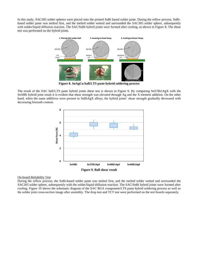
In this study, SAC305 solder spheres were placed onto the printed SnBi based solder paste. During the reflow process, SnBi-
based solder paste was melted first, and the melted solder wetted and surrounded the SAC305 solder sphere, subsequently
with solder/liquid diffusion reaction. The SAC/SnBi hybrid joints were formed after cooling, as shown in Figure 8. The shear
test was performed on the hybrid joints.
SAC305
LTSPaste
SAC305
MeltedLTS
SAC305
SolidifiedLTS
1. Placing SAC solder ball 2. Heating to Peak Temp. 3. Cooling to Room Temp.
Figure 8. SnAgCu ball/LTS paste hybrid soldering process
The result of the SAC ball/LTS paste hybrid joints shear test is shown in Figure 9. By comparing Sn57Bi1AgX with the
Sn58Bi hybrid joint result it is evident that shear strength was elevated through Ag and the X element addition. On the other
hand, when the same additives were present in SnBiAgX alloys, the hybrid joints’ shear strength gradually decreased with
decreasing bismuth content.
0
2
4
6
8
Sn58Bi Sn57Bi1AgX Sn48Bi1AgX Sn40Bi1AgX
She
arFo
rce
[N]
Figure 9. Ball shear result
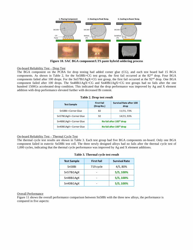
On-board Reliability Test
During the reflow process, the SnBi-based solder paste was melted first, and the melted solder wetted and surrounded the
SAC305 solder sphere, subsequently with the solder/liquid diffusion reaction. The SAC/SnBi hybrid joints were formed after
cooling. Figure 10 shows the schematic diagram of the SAC BGA component/LTS paste hybrid soldering process as well as
the solder joint cross-section image after assembly. The drop test and TCT test were performed on the test boards separately.
SAC305
LTSPaste
SAC305
MeltedLTS
SAC305
SolidifiedLTS
1. Placing Component 2. Heating to Peak Temp. 3. Cooling to Room Temp.
Figure 10. SAC BGA component/LTS paste hybrid soldering process
On-board Reliability Test – Drop Test
The BGA component on the PCBA for drop testing had added corner glue (CG), and each test board had 15 BGA
components. As shown in Table 2, for the Sn58Bi+CG test group, the first fail occurred at the 82nd drop. Four BGA
components failed after 100 drops. For the Sn57Bi1AgX+CG test group, the first fail occurred at the 92nd drop. One BGA
component failed after 100 drops. The Sn48Bi1AgX+CG and Sn40Bi1AgX+CG test groups had no fails after the one
hundred 1500Gs accelerated drop condition. This indicated that the drop performance was improved by Ag and X element
addition with drop performance elevated further with decreased Bi content.
Table 2. Drop test result
Test SampleFirst Fail
(Drop No.)Survival Rate after 100
drop
Sn58Bi + Corner Glue 82 11/15, 73%
Sn57Bi1AgX + Corner Glue 92 14/15, 93%
Sn48Bi1AgX + Corner Glue No fail after 100th drop
Sn40Bi1AgX + Corner Glue No fail after 100th drop
On-board Reliability Test – Thermal Cycle Test
The thermal cycle test results are shown in Table 3. Each test group had five BGA components on-board. Only one BGA
component failed in eutectic Sn58Bi test cell. The three newly designed alloys had no fails after the thermal cycle test of
1,000 cycles, indicating that the thermal cycle performance was improved by Ag and X element additions.
Table 3. Thermal cycle test result
Test Sample First Fail Survival Rate
Sn58Bi 719 cycle 4/5, 80%
Sn57Bi1AgX - 5/5, 100%
Sn48Bi1AgX - 5/5, 100%
Sn40Bi1AgX - 5/5, 100%
Overall Performance
Figure 11 shows the overall performance comparison between Sn58Bi with the three new alloys, the performance is
compared in five aspects:

MeltingTemperature
MechanicalProperties
Hybrid JointsShear Strength
DropReliability
TCTReliability
Sn58Bi
Sn57Bi1AgX
a) MeltingTemperature
MechanicalProperties
Hybrid JointsShear Strength
DropReliability
TCTReliability
Sn58Bi
Sn48Bi1AgX
b) MeltingTemperature
MechanicalProperties
Hybrid JointsShear Strength
DropReliability
TCTReliability
Sn58Bi
Sn40Bi1AgX
c)
Figure 11. Overall performance comparison between eutectic Sn58Bi with (a)Sn57Bi1AgX, (b) Sn48Bi1AgX, (c)
Sn40Bi1AgX
Melting Point
A lower final melting temperature could lower the reflow peak temperature, and hence reduce thermal damage on the PCB
and components. According to the DSC results, the eutectic Sn58Bi and Sn57Bi1AgX had the lowest final melting
temperature among the four alloys.
Mechanical Properties
Higher ductility provides better toughness performance. In this study, Sn57Bi1AgX and Sn48Bi1AgX show the highest
ductility among all the alloys.
Hybrid Ball Shear Test
The compatibility of SnBi-based alloys with SAC305 has been tested. The result showed that Sn57Bi1AgX and
Sn48Bi1AgX have the best hybrid ball shear.
Drop Reliability
The drop test results showed that, after 100 times of a 1500Gs accelerated drop, Sn48Bi1AgX+CG and Sn40Bi1AgX+CG
had no fails.
TCT Reliability
Three newly designed Ag and X element added alloys had no fails after 1,000 thermal cycle testing, indicating that the three
alloys have better performance than the eutectic Sn58Bi.
Conclusions
The result of this study showed that the Bi phase became finer with Ag and X element additions in the SnBi-based alloy, and
hence altered the mechanical performance and reliability of the SnBi-based alloy. It was also found that the three newly
designed alloys have the following features:
1. The solidus and final melting temperature of Sn57Bi1AgX is close to the eutectic SnBi alloy. The Bi phase becomes non-
continuous and needle-like with Ag and X element additions, significantly improving mechanical properties and thermal
cycle reliability.
2. Sn48Bi1AgX has less bismuth content than the eutectic SnBi, hence the final melting temperature is 12˚C greater than the
eutectic SnBi. The thermal cycle performance and drop reliability are better with Ag and X element additions.
3. Sn40Bi1AgX has better performance in the thermal cycle and drop tests than the eutectic SnBi; however, the final melting
temperature is 30˚C greater than the eutectic SnBi, showing that a higher peak temperature is needed.
References
[1] V. Schroeder, J. Gleason, and F. Hua, “Strength and Fatigue Behavior of Joints made with Bi42Sn-1Ag Solder Paste: An
Alternative to Sn-3.5Ag-0.7Cu for Low Cost Consumer Products”, Proceedings of the SMTA International Conference,
2001.
[2] Jasbir Bath, Manabu Itoh, Gordon Clark, Hajime Takahashi, Kyosuke Yokota, Kentaro Asai, Atsushi Irisawa, Kimiaki
Mori, David Rund, Roberto Garcia, “An Investigation Into Low Temperature Tin-Bismuth and Tin-Bismuth-Silver Lead-free
Alloy Solder Pastes for Electronics Manufacturing Applications”, Proceedings of the IPCAPEX Expo Conference, 2012.
[3] Olivia H Chen, Al Molina, Raiyo Aspandiar, Kevin Byrd, Scott Mokler, Kok Kwan Tang, “Mechanical Shock and Drop
Reliability Evaluation of The BGA Solder Joint Stack-ups Formed by Reflow Soldering SAC Solder Balls BGAs WithBiSnAg and Resin Reinforced BiSn-based Solder Pastes”, Proceedings of SMTA International, 2015.