New Flagship R CPU Units: The Ultimate in Speed - OMRON … · Inverter (e.g., 3G3RX) Motor CJ1M...
57
Programmable Controller New Flagship "R" CPU Units: The Ultimate in Speed
Transcript of New Flagship R CPU Units: The Ultimate in Speed - OMRON … · Inverter (e.g., 3G3RX) Motor CJ1M...

Programmable Controller
New Flagship "R" CPU Units: The Ultimate in Speed

The Fast, Small, and Flexible CJ1 Expands the World of Machine Control!
Fast! Small! Flexible!
Upgraded Basic Functions(CJ1H-CPU6 H-R Performance)
Wide Range of CPU UnitsHeight: 90 mm, Depth: 65 mm
Backplane-free structure for
a flexible Rack width.
Smaller Units.
Scan time
PCMIX values
Basic instructions
Floating-point decimal instructions
Interrupt response time
30 Ksteps in 870 µs
17.7
LD 16 ns/OUT 16 ns
Add/subtract: 0.24 µs
Multiply: 0.24 µs
40 µs
Program capacity:
I/O points:
Data memory capacity:
5 to 250 Ksteps
160 to 2,560 points
32 to 448 Kwords
CPU Units are available for a variety of
applications, such as CPU Units with built-in
I/O or CPU Units for loop control.
From Basic I/O Units, Analog Units, and
Position Control Units to Ethernet Units, any of
the Units can be used with any of the CPU
Units.
Application-specific CPU Units
Full Complement of I/O Units
Concept 2
Application-specific CPU Units 8
CPU Units with Built-in I/O 8
Loop-control CPU Units 10
Function Blocks 12
Programming Languages 14
System Design Guide 17
System Configuration
Dimensions
General Specifications
CPU Units
Specifications
Additional CJ1M-CPU21/22/23
Specifications
CJ1G-CPU P (Loop-control CPU Units)
Specifications ...........................
Checking Current Consumption and
Power Consumption...
Ordering Information
Basic Configuration Units................................................
Programming Devices
Optional Products and Maintenance
Products
DIN Track Accessories
Basic I/O Units
Special I/O Units and CPU Bus Units
Versatile Machine Control with the Highest Performance Standards in
the Industry.
Super-compact design that meets the highest standards in its class. Even a narrow space in a machine
serves as a control panel.
Suitable for essentially any application, from small device and temperature control, to large-scale
control over networks.
Conditions: 30 Ksteps, basic-to-special instruction ratio = 7:3, 128 inputs, 128 outputs
18
22
25
27
28
32
35
36
38
42
45
45
46
50
37
2 3
Duct
Duct
Height: 90 mm
G3ZA Multi-point Power Controller
S8VS Power Supply
Common processingInterrupt response
LD instruction execution timeOUT instruction execution time
SIN calculationFloating-point decimal addition and subtraction
Basic I/O Unit, 16 pointsAnalog Input Unit, 8 points
130 µs40 µs
16 ns16 ns
0.59 µs0.24 µs
1.4 µs50 µs
Data Memory
448 words
256 words
128 words
64 words
User Memory
250 Ksteps
120 Ksteps
60 Ksteps
30 Ksteps
Model
CJ1H-CPU67H-R
CJ1H-CPU66H-R
CJ1H-CPU65H-R
CJ1H-CPU64H-R
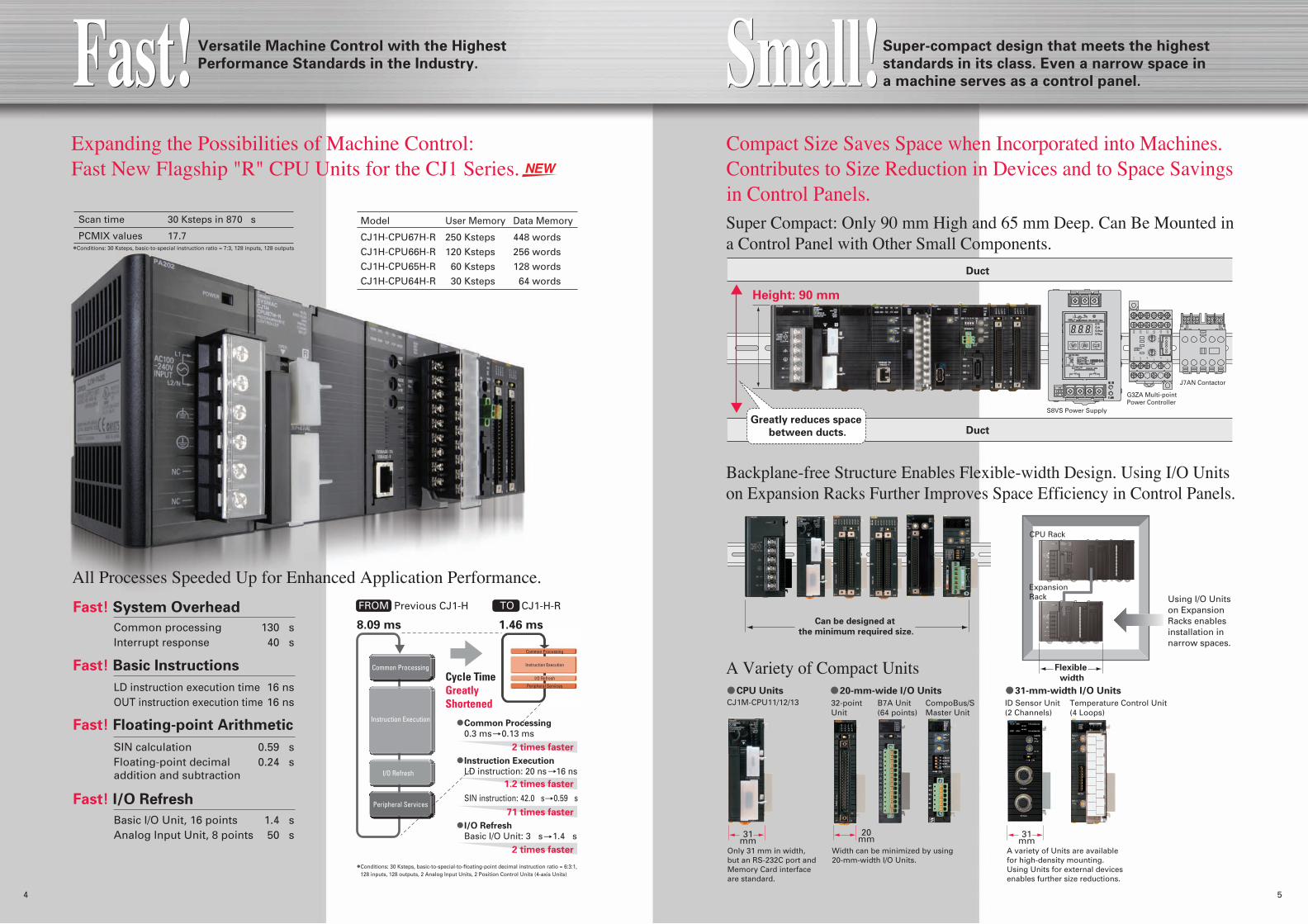
All Processes Speeded Up for Enhanced Application Performance.
Super Compact: Only 90 mm High and 65 mm Deep. Can Be Mounted in a Control Panel with Other Small Components.
Backplane-free Structure Enables Flexible-width Design. Using I/O Units on Expansion Racks Further Improves Space Efficiency in Control Panels.
A Variety of Compact Units
Expanding the Possibilities of Machine Control: Fast New Flagship "R" CPU Units for the CJ1 Series.
Compact Size Saves Space when Incorporated into Machines. Contributes to Size Reduction in Devices and to Space Savings in Control Panels.
Can be designed at
the minimum required size.
Scan time
PCMIX values
30 Ksteps in 870 µs
17.7
Cycle Time Greatly Shortened
Common Processing
0.3 ms 0.13 ms
2 times faster
2 times faster
1.2 times faster
71 times faster
I/O Refresh
Peripheral Services
Instruction Execution
Common Processing
FROM Previous CJ1-H TO CJ1-H-R
8.09 ms 1.46 ms
Instruction Execution
I/O Refresh
Common Processing
Peripheral Services
31mm
20mm
CPU Units
31mm
ID Sensor Unit (2 Channels)
Temperature Control Unit (4 Loops)
CompoBus/S Master Unit
32-point Unit
B7A Unit (64 points)
CJ1M-CPU11/12/13
Only 31 mm in width, but an RS-232C port and Memory Card interface are standard.
Width can be minimized by using 20-mm-width I/O Units.
A variety of Units are available for high-density mounting. Using Units for external devices enables further size reductions.
Fast!Fast! Versatile Machine Control with the Highest
Performance Standards in the Industry. Small!Small!Super-compact design that meets the highest
standards in its class. Even a narrow space in
a machine serves as a control panel.
Fast! System Overhead
Fast! Basic Instructions
Fast! Floating-point Arithmetic
Fast! I/O Refresh
I/O Refresh
Basic I/O Unit: 3 µs 1.4 µs
Instruction Execution
LD instruction: 20 ns 16 ns
SIN instruction: 42.0 µs 0.59 µs
20-mm-wide I/O Units 31-mm-width I/O Units
Greatly reduces space
between ducts.
4 5
J7AN Contactor
Conditions: 30 Ksteps, basic-to-special instruction ratio = 7:3, 128 inputs, 128 outputs
CPU Rack
Expansion Rack
Flexible
width
Conditions: 30 Ksteps, basic-to-special-to-floating-point decimal instruction ratio = 6:3:1, 128 inputs, 128 outputs, 2 Analog Input Units, 2 Position Control Units (4-axis Units)
Using I/O Units on Expansion Racks enables installation in narrow spaces.

320160 640 960 1280 2560Number of I/O points
250 Ksteps
120 Ksteps
60 Ksteps
30 Ksteps
20 Ksteps
10 Ksteps
5 Ksteps
Program
capacity
Select the optimum CPU Unit according to your system requirements.
CJ1G-H/CJ1G-P Loop-control CPU Units
CJ1M/CJ1M with Built-in I/O
CJ1-H-R/CJ1H-H
CJ1G-H/CJ1G-P Loop-control CPU Units
CJ1M/CJ1M with Built-in I/O
CPU Unit
LD 16ns/OUT 16ns
250 to 30 Ksteps
448 to 64 Kwords
2,560
62 mm
None
None
LD 20ns/OUT 20ns
250 to 60 Ksteps
448 to 128 Kwords
2,560
62 mm
None
None
LD 40ns/OUT 40ns
60 to 10 Ksteps
128 to 64 Kwords
1,280 to 960
62 mm
None
None
LD 100ns/OUT 350ns
20 to 5 Ksteps
32 Kwords
640 to 160
31 mm
None
None
LD 100ns/OUT 350ns
20 to 5 Ksteps
32 Kwords
640 to 160
49 mm
16
None
LD 40ns/OUT 40ns
60 to 10 Ksteps
128 to 64 Kwords
1,280 to 960
69 mm
None
50 to 300 blocks
CJ1H-CPU6 H-R
CJ1H-CPU6 H
CJ1G-CPU4 H
CJ1M-CPU1
CJ1M-CPU2
CJ1G-CPU4 P(-GTC)
High-speed Models Advanced Models Standard Models Compact Models with Built-in I/O Loop-control CPU Units
General-purpose CPU Units Application-specific CPU Units
CJ1-H-R/CJ1H-HA wide variety of products, such as high-density mountable connectors and removable terminal blocks, is available to meet your requirements.
Units, such as the B7A, are available for interrupt inputs, quick-response inputs, and reduced I/O wiring.
Input Units and Temperature Control Units are available to handle process data, such as temperatures, currents, and voltages. A complete lineup of models (including models with isolation between channels and high-precision models) is available for a wide range of applications.
Various Units are available for control from High-speed Counter Units to Position Control Units for open-collector and line-driver pulse outputs and MECHATROLINK-II communications and Motion Control Units for applications using motion language.Note: MECHATROLINK-II is a registered trademark of the MECHATROLINK Members Association.
Units are available for general-purpose Ethernet, as well as for data links between PLCs, and the DeviceNet and CompoNet open networks.
Units such as RFID Controllers and Data Collection Units are available to meet a wide range of needs.
29 models total
Units for Special Applications
Basic I/O Units
Positioning Units
Communications Units
Other Units
5 models total
9 models total
5 models total
10 models total
22 models totalAnalog, Process-control, and Temperature Control Units
6 7
Basic instructions
CPU11/21Data Memory32 Kwords
CPU12/22Data Memory32 Kwords
CPU13/23Data Memory32 Kwords
CPU43H/43PData Memory64 Kwords
CPU42H/42PData Memory64 Kwords
CPU45H/45PData Memory128 Kwords
CPU44H/44PData Memory64 Kwords
CPU67H-R/67HData Memory448 Kwords
CPU66H-R/66HData Memory256 Kwords
CPU65H-R/65HData Memory128 Kwords
CPU64H-RData Memory64 Kwords
FlexibleFlexible Suitable for any application, from small device and te mperature control,
to large-scale control over networks.
A Wide Variety of CPU Units and Other Units to Handle Virtually Any Type of Machine Control.
A Complete Lineup of CPU Units, from Low-end to High-end
A Wide Selection of CPU Units to Match the Application
Despite the wide variety of models, memory allocations, instructions, and I/O Units are all compatible. This makes it easy to design migration from large-scale systems to small devices.
Wide Selection of Unit GroupsChoose from a wide range of Units, from Basic I/O Units, Analog Units, and Position Control Units to Ethernet Units. All can be used with any of the CPU Units.
Width
Built-in I/O
Loop control
Number of I/O points
Data memory capacity
Program capacity
For Applications Requiring Speed
For Large-scale Applications Requiring Large Memory Capacity
For Applications Requiring Large Memory Capacity, such as Data Management
For Small-scale Applications such as Automated Machines and Inspection Devices
For Applications Requiring Versatile, High-precision Position Control
For Applications Requiring Sequence Control and Analog Control

Up to four interrupt inputs or quick-response inputs can be used. For quick-response inputs, detection is possible for pulse
Widths as short as 30 µs. Interrupt response uses high-speed response Processing at 93 µs. Interrupts can be created for ON signals or OFF signals.
Up to two high-speed counter inputs can be used by connecting rotary encoders to built-in inputs. High-speed counting for a 24-VDC input at 60 kHz for single-phase and 30 kHz for differential phases.
High-speed counting for line-driver inputs at 100 kHz for single-phase and 50 kHz for differential phases.
Achieve More Flexible and Precise Machine Control with Built-in Pulse I/O.
CPU Units with Built-in I/O
CJ1M-CPU2
8 9
Application-specific CPU Units
High-speed, Flexible Programming Is Made Easy by Simply Pasting OMRON Function Blocks for Positioning.
Input interrupts: 4 pointsHigh-speed counter inputs: Single-phase, 100 kHz, 2 axes or Differential phases, 50 kHz, 2 axesPulse outputs: 100 kHz, 2 axes One PWM output (CPU21) Two PWM outputs (CPU22/CPU23)Note: The above functions can all be used simultaneously.
High-precision Interrupt Positioning
Inverter (e.g., 3G3RX)
Motor
CJ1M
High-speed counter input
High-speed counter input
I/O
Incremental encoder
Incremental encoder
From stepping motors to servos, positioning control can be easily achieved using pulse outputs for one or two axes. Pulse output control is enabled from 1 Hz to 100 kHz. Startup times as fast as 46 µs reduce tact times and enable high-precision positioning. A high-precision variable duty ratio (PWM) can be output in 0.1% increments and used in applications such as lighting and electric power control. Using special instructions and OMRON Function Blocks for positioning makes programming easy even for first-time users.
High-speed interrupts can be processed using target value matching or zone comparison interrupts.The frequency (speed) can be easily measured by using a special instruction (PRV2). Ideal for applications such as measuring the speed of rotating bodies for inspections or detecting conveyer speeds. Can also be used for monitoring accumulated motor rotations.
High-speed Counter in Linear Mode
Ideal for applications such as conveyors.
Trapezoidal
Acceleration/
Deceleration
Positioning
OMRON Function Blocks and special instructions make position control easy. Detailed functions are provided for reducing out-of-step operation for stepping motors and eliminating error downtime.
Changing the
Target Position
during Positioning
The target position can be changed during positioning. It is also possible to reverse direction when changing the target position.
Interrupt Feeding
It is possible to change to positioning control during speed control. Interrupt feeding can be executed after the interrupt for a specified number of pulses.
Sequential
Positioning
Travel to multiple preset points can be specified. This is effective for applications such as positioning loaders and unloaders at multiple points.
Positioning control variations Operation patterns Application examples
Special instructions, OMRON Function Blocks
Target speed control
Specified number of travel pulses
Acceleration
Start frequency
Deceleration
S-curve acceleration
S-curve deceleration
Acce-leration
Trapezoidal control (PLS2 instruction)
Travel startTarget position
(frequency, acceleration/
deceleration) changed
PT
Servomotor
Servo Driver(e.g., SMARTSTEP 2)
Controller
RS-232CCamera
Positioning control executed
Speed control (ACC instruction)
Setting Acceleration and Deceleration SeparatelyThe optimum speed curve can be set ac-cording to acceleration and deceleration tor-que.
Basic Form
PCB Rack Positioning
Basic Conveyor Rail Width Positioning
Position Control Using Data Measured at Startup
Sheet feeding direction
Product Variations
Model User memory Data memory
CJ1M-CPU21 5 Ksteps 32 KwordsCJ1M-CPU22 10 Ksteps 32 KwordsCJ1M-CPU23 20 Ksteps 32 Kwords
Built-in I/O
Input Interrupts
Pulse Outputs
High-speed Counters
Origin Search
An origin search or return operation can be executed with a single command. A wide range of origin search patterns is available, so the optimum origin search pattern can be selected for the machine design. When a Servomotor is used, position deviation is minimized by a deviation counter reset output. Positioning
Speed control or positioning using relative or absolute coordinates can be executed with a single command. A wide range of functions is available for positioning to suit your application.
• Changing the Target Position with Another Instruction
S-curve Accelera- tion/Deceleration SettingUsed to reduce vibra-tion during high-speed positioning.
Triangular ControlA fatal error does not occur even if settings do not allow the target speed to be reached.
Achieved with a single OMRON Function Blocks for specifying absolute (or relative) travel.
• Move Absolute (REAL)• Move Absolute (DINT)• Move Relative (REAL)• Move Relative (DINT)
While position is being controlled by a PLS2 instruction, another PLS2 instruction can be used to override the first PLS2 instruction.
• Starting Trapezoidal Control
Achieved with a single OMRON Function Block for interrupt feeding.
• Interrupt Feeding (REAL)• Interrupt Feeding (DINT)A specified number of
pulses are output and then positioning stops.
Uniform distance from detection of mark until
heat welding
Achieved with a single OMRON Function Block for specifying sequential positioning.
High-speed Counter in Linear Mode
Ideal for applications such as electronic component index tables.
CJ1M

Loop-control CPU UnitsCJ1G-CPU4 P
CJ1G-CPU4 P-GTC
10 11
In Addition to Sequence Control, an Engine for Controlling Analog Quantities Is Built Into the CPU Unit.
Model User Memory Data Memory Function blocks
CJ1G-CPU42P 10 Ksteps 64 Kwords 50CJ1G-CPU43P 20 Ksteps 64 Kwords 300CJ1G-CPU44P 30 Ksteps 64 Kwords 300CJ1G-CPU45P 60 Ksteps 128 Kwords 300CJ1G-CPU45P-GTC 60 Ksteps 128 Kwords 300
Seq
uen
ce C
on
tro
l E
ng
ine
Lo
op
Co
ntr
ol
En
gin
e
CPU Element:
CJ1G-CPU4 HCX-ProgrammerSequence Control Program (Ladder, FB, ST)
CX-ProcessLoop Control Program (Function Blocks)
69 mm
Depth: 65 mm
90 mm
Loop-control CPU Unit
Note: For basic instructions only.
Note: For a normal case. (Example: Single loop configuration, A14 terminal + segment linearizer + basic PID + Ao4 terminal)
Analog Input Field Terminal
MV
DVSPPVY1
Y2Y3Y4Y5Y6Y7Y8
RSP
Basic PID Split conversion
Y1X1
Y2
Bank conversion
Y1X1 X1 C_BNKC_PIDC_SPC_PC_IC_DC_MHC_ML
Y2
Segment Program 2
X1
X2
X3X4X5
X6
X7X8
Analog Output Field Terminal
Engineering Example: Program Control
SP
TIC
Input CH1
Output CH1
Output CH2
Time
RSP
PV MV
Temperature input
Heater output Control valve
(coolant)
Loop-control CPU Unit
Disturbance
Disturbance
Stabilization time
Overshooting
Stabilization time lengthened
Faster recovery
CX-Process Tool (Software for Personal Computer) Face Plate Auto-Builder for NS
Segment program parameter setting screen
Tuning Screen
NT-series PT
Loop-control CPU Unit
Serial or Ethernet
Control Screen
Y1
Y2Y3Y4
X1
X2X3X4
PV
RSP MV
Analog Output Field Terminal
Analog Input Field Terminal
Y1
Segment Program
Basic PID
20-Kstep ladder program executed in 1 ms. (See note.)
20 loops of PID control executed in 10 ms. (See note.)
Easy Programming Using Function Blocks
Gradient temperature control equalizes the temperatures at multiple points, providing high-quality heat processing, reducing energy loss until temperatures stabilize, and saving labor in adjustments due to interference between heaters.
Loop Controller Element:
50 or 300 Function Blocks
Split Converter
Analog Input Unit
Analog Output Unit
Note: CJ1G-CPU45P-GTC only.
Example: Planar Temperature Control of Multi-stage Furnaces, Wafer and Glass Surface Temperatures, and Other Applications.
Average temperature controlled.
Temperature differences controlled.
Interference at other control output points suppressed.
Gradient temperature control
CPU: CJ1G-CPU45P-GTC
New Algorithms for Stabilizing Control
Adjusting for Disturbance OvershootingOptimum Tuning for the Application
Fine-tuning Function
A function is provided to suppress overshooting due to disturbances for faster stabilization.Example
•Temperature drops when objects are placed in a batch furnace•Disturbance when control is changed
Values such as the PV, SP, and MV can be monitored and adjusted on the Tuning Screen, and the data can be saved as a CSV file. An auto-tuning (AT) function and a fine-tuning (FT) function are also supported for automatic calculation of PID constants.
Suitable for any application, from small device and loop control to large-sca le control over networks.
Application-specific CPU Units
Product Variations
Programming is made easy by combining function blocks such as PID control and square root calculations and then connecting them with a mouse.
Even complex control operations can be managed, such as program control, cascade control, and feed- forward control. PID parameters can be adjusted on the special Tuning Screens.
Tuning and Automatic Screen Generation
Temperature Control Algorithms with a Proven Track Record
Gradient Temperature Control for Planar Temperature Control Across Multiple Points (See note.)
Tuning Screens that are convenient for adjusting PID parameters can be easily started. The screens required during operation can be automatically generated, thereby reducing development work.
A Tuning Screen can be easily started by right-clicking the mouse over the function block. When combined with an NS-series PT, the touch panel screen required for loop control startup and operation is generated automatically with just one button.
Combine function blocks and connect them graphically using the mouse. Touch panel windows are automatically generated.
Adjust PID constants and other parameters on the Tuning Screen.
OMRON's many years of accumulated know-how in temperature and process control have been condensed to create easy-to-use algorithms with proven results in providing solutions to problems.
Previous: PID Gain Adjustment
New: Adjusting for Disturbance
Overshooting
Data acquired from Analog Input Unit
Control output from Analog Output Unit
Execute PID
control!
Change the PID
constants according
to the set point!
Use program
control!
Implement heating
and cooling control!
Right in!Right in!Right in!Right in!
Right in!Right in!
Right in!Right in!
Easy!Easy!
12 13
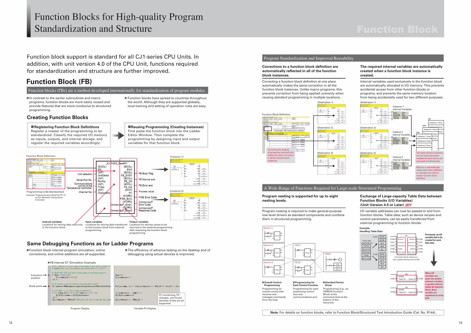
Creating Function Blocks
Same Debugging Functions as for Ladder Programs
Internal variables
Locations for storing data used only in the function block.
Programming to Be StandardizedExample: Programming to Read the PV of an EJ1 Modular Temperature Controller
Input variables
Locations for storing data transferred to the function block from external programming.
Output variables
Locations for storing values to be returned to the external programming after executing the function block programming.
Registering Function Block DefinitionsRegister a master of the programming to be standardized. Classify the required I/O memory as inputs, outputs, and internal storage, and register the required variables accordingly.
Correcting a function block definition at one place automatically makes the same correction in all the function block instances. Unlike macro programs, this prevents correction from being applied unevenly when reusing standard programming in multiple locations.
[Instance 2]
[Destination 2]
[Destination 3]
[Instance 1]Function Block Definition
[Destination 1]
[Destination 2]
[Destination 3]
[Destination 1]
Instance 1 Internal Variables
Instance 2 Internal Variables
Instance 3 Internal Variables
Function Block Definition
Function blocks (FBs) are a method developed internationally for standardization of program modules.
Program Standardization and Improved Reusability
A Wide Range of Functions Required for Large-scale Structured Programming
Function block support is standard for all CJ1-series CPU Units. In addition, with unit version 4.0 of the CPU Unit, functions required for standardization and structure are further improved.
Function Block (FB)
In contrast to the earlier subroutines and macro programs, function blocks are more easily reused and provide features that are more conducive to structured programming.
Function block internal program simulation, online corrections, and online additions are all supported.
The efficiency of advance testing on the desktop and of debugging using actual devices is improved.
Function blocks have spread to countries throughout the world. Although they are supported globally, local training and setting of operation rules are easy.
Reusing Programming (Creating Instances) First paste the function block into the Ladder Editor Window. Then complete the programming by assigning input and output variables for that function block.
Corrections to a function block definition are
automatically reflected in all of the function
block instances.
Program nesting is required to make general-purpose low-level drivers as standard components and combine them in structured programming.
Program nesting is supported for up to eight
nesting levels.
I/O variable addresses can now be passed to and from function blocks. Table data, such as device recipes and control parameters, can be easily transferred from external programming to function blocks.
Exchange of Large-capacity Table Data between
Function Blocks (I/O Variables)
(Unit Version 4.0 or Later)
Internal variables used exclusively in the function block are automatically allocated in I/O memory. This prevents accidental access from other function blocks or programs, and prevents the same memory location from being accidentally used for two different purposes.
The required internal variables are automatically
created when a function block instance is
created.
MOV
data 0
data 1
FB100
FB201
Section 1
Section 2
Section 3
FB101
FB102
FB002
FB201
FB201
FB101
Overall Control
Programming
Programming for overall control that receives and manages commands from the host.
Example:
Handling Table Data
Vertical i
Horizontal i
Thickness i
Height i
Color code i
Vertical o
Horizontal o
Thickness o
Height o
Color code o
&120
&160
&10
&90
&1
&918
&730
&12
&15
&3
D105
D100D100
D101
D102
D103
D104
D100
D101
D102
D103
D104
FB
FB
A function block instance is also created starting from D105.
D100 D100WORDTable [5] --- Table [5]
D105 D105
Vertical
Horizontal
Thickness
Height
Color code
Table data specifications
DM
WR
HR
FBWORDTable [5] --- Table [5]
When I/O variables are used, the number external variables is greatly reduced. Inside the function block, these variable are registered as array data.
Previously, an I/O variable had to be created for each data item.
Instance 1 Area
Instance 2 Area
Instance 3 AreaInstance 1 Area
Instance 2 Area
Instance 3 AreaInstance 1 Area
Instance 2 Area
Instance 3 Area
The same memory locations are not used even when multiple function blocks are executed simultaneously.
Memory is automatically reallocated when additions or changes are made to master function block definition.
Correcting the original programming automatically makes the same correction in all the function block instances.
Execution position
Break point
Program Display Variable PV Display
FB Internal ST Simulation Example
Note: For details on function blocks, refer to Function Block/Structured Text Introduction Guide (Cat. No. R144).
Example: OR instruction added.
Function Blocks for High-quality Program Standardization and Structure
PV monitoring, PV changes, and forced set/reset of bits are all supported.
Programming for
Each Control Function
Programming for each positioning control axis and communications port.
Standard Device
Driver
Programming (e.g., an OMRON Function Block) at the command level at the bottom of the hierarchy.

14 15
StepExpresses a single process within the overall processing. When a step is activated, the actions defined in that step are executed.
V520-R221FH/SH Bar Code Reader
CPU Unit
RS-232C
Ethernet Unit
RecvDataRead values
NS
SFC Simulation
Transition Forced Set/Reset
Set status display
Step 1
Step 2
Step 3
Step 4
FALSETrans 1 FALSETrans 2
FALSETrans 4
FALSETrans 3
Action written in ladder language including a FB
Action written in ST language including a FB
Note: For details on sequential function charts, refer to SFC Introduction Guide (Cat. No. R149).
Information stored as text strings acquired from a bar code reader can be displayed on a PT.
(Unit Version 4.0 or Later)
Note: For details on Structured Text (ST), refer to Function Block/Structured Text Introduction Guide (Cat. No. R144).
Expanded Support for Languages Conforming to IEC 61131-3 Standard. Greater Selection of Programming Languages for Various Applications
Sequential Function Chart (SFC)The Sequential Function Chart (SFC) language is ideal for programming changes in system status.
Structured Text (ST)Structured Text (ST) is a language developed for FA control and is effective for complex numeric and text-string processing.
SFCs can be used to express changes in overall device processes, making it easy to perform debugging and maintenance for overall system operation.
Parallel branching and joining of multiple processes executed in parallel, and conditional branching and joining of individually selected processes, can be written graphically.
Programming such as conditional branching, repeated executions, and text-string control can be written more easily than with ladder programs.
Because ST is a text language, maintenance and reusability are easy due to the high generality and readability.
ActionExpresses an individual process within a step. Actions can contain bits or programs. A number of different types of actions can be defined in a single step.
TransitionPlays the role of a gate for moving the active status to the next step. The transition condition can be a bit or a program.
SFC programming can use program components structured with function blocks to take advantage of the superior reusability of function blocks.
Ladder and ST language can be used for the
action and transition programs, and can include
function blocks.
The ST language can be used according to the application, e.g., in function blocks for program standardization or in tasks for programming specific applications. The ST language can also be used to call function blocks, as well as for structuring program resources.
Use ST Not Only in Function Blocks But Also in
Tasks (Unit Version 4.0 or Later)
Text string data can be written directly into programs, allowing the data to be intuitively understood.
Convenient for text strings used for PTs and
BCR. The STRING data type is supported.
(Unit version 4.0 or later)SFC programming offers the same superior debugging functions as provided for ladder programming. In addition, forced setting and resetting are supported for steps and transitions.
Superior debugging functions are supported,
such as online editing and simulation.
The ST language can now be used directly in tasks.
Previously, the ST language could be used only in function blocks.
Product ID: Z1234567-8-05727
Lot No.
Example: Control Syntax
Conditional branching : IF, THEN, ELSE/CASE, ELSE
Repeated execution : FOR/WHILE loop
Example: Numeric Processing Functions
Trigonometric functions : SIN, COS, TAN, ASIN, ACOS, ATAN
Absolute values : ABS
Logarithms : LOG, LN
Square roots : SQRT
Exponents : EXP, EXPT
The Optimum Programming Language for Various Control Functions, such as Device Status Changes and Numeric Proce ssing

16
MEMO

System Design Guide
System Configuration ......................................................................................18
Dimensions ......................................................................................................22
General Specifications .....................................................................................25
CPU Units ........................................................................................................27
Specifications ...................................................................................................28
Additional CJ1M-CPU21/22/23 Specifications .................................................32
CJ1G-CPU@@P (Loop-control CPU Units) Specifications ...............................35
Checking Current Consumption and Power Consumption ...............................36
17

System Configuration
Basic System
POWER
PA205R
DC24VAC240V
OUTPUTRUN
INPUTAC100-240V
L2/N
L1
CONTROLLER
CJ1G-CPU44SYSMAC
PROGRAMMABLEERR/ALM
RUN
COMM
INHPRPHL
OPEN
PERIPHERAL
BUSY
MCPWR
PORT
CPU Rack (Backplane-free Structure)
Expansion Rack (Backplane-free Structure)
Memory Card
HMC-EF183
Peripheral Port Cable
Personal Computer CableCS1W-CN226/626
Programming Devices
CX-One (e.g., CX-Programmer)Programming Console
RS-232C Cable for PT
XW2Z-200T/600T
RS-232C Cable for Personal Computer
XW2Z-200S/500S-CV
RS-422A Adapter
CJ1W-CIF11
CS1 Expansion Cables
CS1W-CN@@3(30 cm, 70 cm, 2 m, 3 m,
5 m, 10 m, 12 m)
Programmable Terminal (PT)
NS Series
CJ1 Basic I/O UnitsCJ1 Special I/O UnitsCJ1 CPU Bus UnitsNote: A maximum of 10 Units can be mounted.
CJ1 Power Supply Units
CJ1W-PA205CCJ1W-PA205RCJ1W-PA202CJ1W-PD025CJ1W-PD022
CJ1 CPU Units
CJ1H-CPU6@H-RCJ1H-CPU6@HCJ1G-CPU4@HCJ1M-CPU1@CJ1M-CPU2@CJ1G-CPU4@P (-GTC)
CJ1 I/O Control Unit
CJ1W-IC101
CJ1 End Cover
CJ1W-TER01
CJ1 I/O Interface Unit
CJ1W-II101
18 Programmable Controllers SYSMAC CJ1

Configuration Units
CJ1 Basic I/O Units
8-point Units 16-point Units 32-point Units 64-point Units
Input Units
DC Input UnitCJ1W-ID201 AC Input UnitCJ1W-IA201
DC Input UnitCJ1W-ID211 AC Input UnitCJ1W-IA111
DC Input UnitCJ1W-ID231CJ1W-ID232
DC Input UnitCJ1W-ID261CJ1W-ID262
Output Units
Transistor Output UnitsCJ1W-OD201CJ1W-OD202 Triac Output UnitCJ1W-OA201 Relay Contact Output Unit
(independent commons) CJ1W-OC201
Transistor Output UnitsCJ1W-OD211CJ1W-OD212 Relay Contact Output UnitCJ1W-OC211
Transistor Output UnitsCJ1W-OD231CJ1W-OD232CJ1W-OD233
Transistor Output UnitsCJ1W-OD261CJ1W-OD262CJ1W-OD263
I/O Units
--- ---
(16 inputs, 16 outputs) DC Input/Transistor Output UnitsCJ1W-MD231CJ1W-MD232CJ1W-MD233
32 inputs, 32 outputs DC Input/Transistor Output UnitsCJ1W-MD261CJ1W-MD26332 inputs, 32 outputs TTL I/O UnitCJ1W-MD563
Other Units
---
Interrupt Input UnitCJ1W-INT01
---
B7A Interface Units(64 inputs)CJ1W-B7A14
(64 outputs)CJ1W-B7A04
(32 inputs, 32 outputs)CJ1W-B7A22
High-speed Input UnitCJ1W-IDP01
CJ1 Special I/O Units and CPU Bus Units
Process I/O Units Isolated-type Units with Universal
InputsCJ1W-PH41U
CJ1W-AD04U
Isolated-type Thermocouple Input Units
CJ1W-PTS15CJ1W-PTS51
Isolated-type Resistance Thermometer Input Units
CJ1W-PTS16CJ1W-PTS52
Isolated-type DC Input UnitCJ1W-PDC15
Analog I/O Units Analog Input UnitsCJ1W-AD081-V1CJ1W-AD041-V1
Analog Output UnitsCJ1W-DA08VCJ1W-DA08CCJ1W-DA041CJ1W-DA021
Analog I/O UnitsCJ1W-MAD42
Temperature Control UnitsCJ1W-TC001, CJ1W-TC002CJ1W-TC003, CJ1W-TC004CJ1W-TC101, CJ1W-TC102CJ1W-TC103, CJ1W-TC104
High-speed Counter UnitsCJ1W-CT021
Position Control UnitsCJ1W-NC113CJ1W-NC213CJ1W-NC413CJ1W-NC133CJ1W-NC233CJ1W-NC433
MECHATROLINK II-compatible Position Control Unit
CJ1W-NCF71
MECHATROLINK II-compatible Motion Control Unit
CJ1W-MCH71
Serial Communications UnitsCJ1W-SCU21-V1CJ1W-SCU31-V1CJ1W-SCU41-V1
Ethernet UnitCJ1W-ETN21
Controller Link UnitsCJ1W-CLK21-V1CJ1W-CLK23
FL-net UnitCJ1W-FLN22
DeviceNet UnitCJ1W-DRM21
CompoNet Master UnitCJ1W-CRM21
CompoBus/S Master UnitCJ1W-SRM21
ID Sensor UnitsCJ1W-V680C11
CJ1W-V680C12
CJ1W-V600C11
CJ1W-V600C12
High-speed Data Storage UnitCJ1W-SPU01-V2
Available soon
Available soon
Programmable Controllers SYSMAC CJ1 19

CJ-series CPU RacksA CJ-series CPU Rack consists of a CPU Unit, Power Supply Unit, Configuration Units (Basic I/O Units, Special I/O Units, and CPU Bus
Units), and an End Cover.
Required Units
Types of Units In the SYSMAC CJ Series, Units are classified into the following three types. The number of Racks differs depending on the type.
Rack Unit name Required number of Units
CPU Rack
Power Supply Unit 1
CPU Unit 1
I/O Control Unit Required only for mounting to an Expansion Rack.
Number of Configuration Units10 max. (Same for all models of CPU Unit.)(The number of Basic I/O Units, Special I/O Units, and CPU Bus Units can be varied. The number does not include the I/O Control Unit.)
End Cover 1 (Included with CPU Unit.)
Type Appearance (example) Description Unit recognition method No. of Units
Basic I/O Units Basic I/O Units provide up to 128 I/O points, withcontact inputs and contact outputs.
Recognized by the CPU Unit accord-ing to the position of the Rack and slot.
No restrictions.
Special I/O Units
Special I/O Units provide more advanced functionsthan do Basic I/O Units, including I/O other thancontact inputs and contact outputs.Examples of Special I/O Units are Analog I/OUnits and High-speed Counter Units. They differfrom CPU Bus Units (including Network Communi-cations Units) in having a smaller area forexchanging data with the CPU Unit.
Recognized by the CPU Unit accord-ing to the unit number (0 to 95) set with the rotary switches on the front panel.
A maximum of 96 Units can be connected. (Multi-ple unit numbers are allo-cated per Unit, depending on the model and settings.)
CPU Bus Units CPU Bus Units exchange data with the CPU Unit via the CPU Bus.Examples of CPU Bus Units are Network Commu-nications Units and Serial Communications Units. They differ from Special I/O Units in having a larger area for exchanging data with the CPU Unit.
Recognized by the CPU Unit accord-ing to the unit number (0 to F) set with the rotary switch on the front panel.
A maximum of 16 Units can be mounted.
POWER
PA205R
DC24VAC240V
OUTPUTRUN
INPUTAC100-240V
L2/N
L1
CONTROLLER
CJ1G-CPU44SYSMAC
PROGRAMMABLEERR/ALM
RUN
COMM
INHPRPHL
OPEN
PERIPHERAL
BUSY
MCPWR
PORT
CPU Rack
End CoverCJ1W-TER01(One End Cover is provided as a standard accessory with the CPU Unit.)
Power Supply UnitCJ1W-P@@@ (@)
CPU UnitCJ1@-CPU@@ (@)
I/O Control UnitCJ1W-IC101(Required only when connecting to an Expansion Rack.)
CJ-series Basic I/O UnitsCJ-series Special I/O UnitsCJ-series CPU Bus Units
Total: 10 Units max
20 Programmable Controllers SYSMAC CJ1

CJ-series Expansion RacksA CJ-series Expansion Rack consists of a Power Supply Unit, an I/O Interface Unit, Configuration Units (Basic I/O Units, Special I/O
Units, and CPU Bus Units), and an End Cover.
Required Units
Note 1. Mounting the I/O Control Unit in any other location may cause faulty operation.2. Mounting the I/O Interface Unit in any other location may cause faulty operation.
Maximum Number of Configuration Units That Can Be Mounted
Rack Unit name Required number of Units
CPU Rack I/O Control Unit One Unit. Required only when an Expansion Rack is used. Mount the I/O Control Unit immediately to the right of the CPU Unit. (See note 1.)
Expansion Rack
Power Supply Unit One Unit
I/O Interface Unit One Unit. Mount the I/O Interface Unit immediately to the right of the Power Supply Unit. (See note 2.)
Number of Configuration Units Ten Units max. (The number of Basic I/O Units, Special I/O Units, and CPU Bus Units can be varied.This number does not include the I/O Interface Unit.)
End Cover One (Included with the I/O Interface Unit.)
CPU Unit Model Total Units No. of Units on CPU Rack No. of Expansion Racks
CJ1H CJ1H-CPU67H-R/67H 40 10 per Rack 3 Racks x 10 Units
CJ1H-CPU66H-R/66H
CJ1H-CPU65H-R/65H
CJ1H-CPU64H-R
CJ1G CJ1G-CPU45H/45P (-GTC)
CJ1G-CPU44H/44P
CJ1G-CPU43H/43P 30 10 per Rack 2 Racks x 10 Units
CJ1G-CPU42H/42P
CJ1M CJ1M-CPU13 20 10 per Rack 1 Rack x 10 Units
CJ1M-CPU23
CJ1M-CPU12 10 10 per Rack Cannot be connected.
CJ1M-CPU11
CJ1M-CPU22
CJ1M-CPU21
Power Supply UnitCJ1W-P@@@(@)
CPU UnitCJ1@-CPU@@@(@)
I/O Control UnitCJ1W-IC101
I/O Interface UnitCJ1W-II101
Power Supply UnitCJ1W-P@@@(@)
CPU Rack
Expansion Rack
Expansion Rack
Number of Expansion Racks: None, 1, 2, or 3 (Depends on CPU Unit model.)
I/O Connecting CableCS1W-CN@@3
Configuration Units: 10 max.
I/O Interface UnitCJ1W-II101
CJ1W-P@@@(@)Power Supply Unit
CJ1W-II101I/O Interface Unit
CJ1W-P@@@(@)Power Supply Unit
I/O Connecting CableCS1W-CN@@3
I/O Connecting Cable CS1W-CN@@3
Expansion Rack
Totalcablelength≤ 12 m
Configuration Units: 10 max.
Configuration Units: 10 max.
Configuration Units: 10 max.
Programmable Controllers SYSMAC CJ1 21

Dimensions
Note: Units are in mm unless specified otherwise.
Product Dimensions
Power Supply Units, CPU Units, and End Covers
CPU Units
Units of Width 20 mm
I/O Control Unit 32-Point I/O Units (CJ1W-ID223@/OD23@)
35.4
27
27.6
65
90
W
Example Rack Widths using CJ1WPA202 Power Supply Unit (AC, 14 W)No. of Units mounted with 31-mm width
Rack width (mm)
With CJ1M-CPU11/12/13
With CJ1M-CPU21/22/23
With CJ1H-CPU@@H-R, CJ1H-CPU@@H, or CJ1G-CPU@@H
With CJ1G-CPU@@P(-GTC) CPU Unit
1 121.7 139.7 152.7 159.7
2 152.7 170.7 183.7 190.7
3 183.7 201.7 214.7 221.7
4 214.7 232.7 245.7 252.7
5 245.7 263.7 276.7 283.7
6 276.7 294.7 307.7 314.7
7 307.7 325.7 338.7 345.7
8 338.7 356.7 369.7 376.7
9 369.7 387.7 400.7 407.7
10 400.7 418.7 431.7 438.7
Unit/product Model Width
Power Supply Unit
CJ1W-PA205C 80
CJ1W-PA205R 80
CJ1W-PA202 45
CJ1W-PD025 60
CJ1W-PD022 27
CPU Unit
CJ1M-CPU1@ 31
CJ1M-CPU2@ 49
CJ1H-CPU@@H-RCJ1H-CPU@@HCJ1G-CPU@@H
62
CJ1G-CPU@@P 69
End Cover CJ1W-TER01 14.7
6581.6
W
90
W=27: CJ1W-PD022W=45: CJ1W-PA202W=80: CJ1W-PA205R CJ1W-PA205CW=60: CJ1W-PD025
14.7
90
34
38.8
RS-422A Adapter CJ1W-CIF11
Power Supply Units End Cover (included with CPU Units)
CJ1H-CPU@@H-RCJ1H-CPU@@HCJ1G-CPU@@H
CJ1G-CPU@@P CJ1M-CPU11/12/13 CJ1M-CPU21/22/23
Unit/product Model Width
I/O Control Unit CJ1W-IC101
20
32-point Basic I/O UnitsCJ1W-ID231/232
CJ1W-OD231/232/233
B7A Interface UnitCJ1W-B7A22CJ1W-B7A14CJ1W-B7A04
CompoBus/S Master Unit CJ1W-SRM21
Space Unit CJ1W-SP001
90
2.7
2.7
6273.9
65
CONTROLLER
CJ1G-CPU44PSYSMAC
PROGRAMMABLEERR/ALM
RUN
COMM
INHPRPHL
OPEN
PERIPHERAL
BUSY
MCPWR
PORT
LCB03 EXECRDY
INNER LOOP CONTROLLER
90
2.7
2.7
6973.9
65 6573.9
90
2.7
2.7
31
90
2.7
2.7
654983.6
83.7
90
2.7
2.7(140)
6569.3
68
20 65
90
2.7
2.7
2066.5
6583.6
Fujitsu connector MIL connector
(112.5)
22 Programmable Controllers SYSMAC CJ1

Units of Width 31 mm
64-point Basic I/O Units and 32-point Basic I/O Units (CJ1W-MD23@)
Special I/O Units and CPU Bus Units
Unit of Width 51 mm
SYSMAC SPU (High-speed Data Storage Unit)CJ1W-SPU01-V2
Unit of Width 79.8 mm
MECHATROLINK-II compatible Motion Control UnitCJ1W-MCH71
Unit Model Width
I/O Interface Unit CJ1W-II101
31
8/16-point Basic I/O Units
CJ1W-ID201CJ1W-ID211CJ1W-IA111/201CJ1W-OD20@CJ1W-OD211/212CJ1W-OC201/211CJ1W-OA201
32-point Basic I/O UnitsCJ1W-MD231CJ1W-MD232/233
64-point Basic I/O Units
CJ1W-ID261CJ1W-OD261CJ1W-MD261
CJ1W-ID262CJ1W-OD262/263CJ1W-MD263CJ1W-MD563
Interrupt Input Unit CJ1W-INT01
High-speed Input Unit CJ1W-IDP01
Analog I/O UnitsCJ1W-AD@@@-V1CJ1W-DA@@@CJ1W-MAD42
Process Input Units
CJ1W-AD04UCJ1W-PH41UCJ1W-PTS51/52/15/16CJ1W-PDC15
Temperature Control Units CJ1W-TC@@@
Position Control UnitsCJ1W-NC113/133CJ1W-NC213/233CJ1W-NC413/433
MECHATROLINK-II compat-ible Position Control Unit
CJ1W-NCF71
High-speed Counter Unit CJ1W-CT021
ID Sensor Units
CJ1W-V680C11CJ1W-V680C12CJ1W-V600C11CJ1W-V600C12
Controller Link UnitsCJ1W-CLK23CJ1W-CLK21-V1
Serial Communications Units
CJ1W-SCU41-V1CJ1W-SCU21-V1CJ1W-SCU31-V1
Ethernet Unit CJ1W-ETN21
DeviceNet Unit CJ1W-DRM21
CompoNet Master Unit CJ1W-CRM21
FL-net Unit CJ1W-FLN22
(140)68
90
2.7
2.7
653169.3
90
2.7
2.7
31 6589
I/O Interface Unit 8/6-point Basic I/O Units,Interrupt Input Unit, and High-speed Input Unit
(112.5)
MIL connector
6566.5
90
2.7
2.7
31
Fujitsu connector
6583.6
90
2.7
2.7
31
Unit Model Width
SYSMAC SPU(High-speed Data Storage Unit)
CJ1W-SPU01-V2 51
6551 9
2.7
90
2.7
Unit Model Width
MECHATROLINK-II compat-ible Motion Control Unit
CJ1W-MCH71 79.8
90
79.8 6570.9
Programmable Controllers SYSMAC CJ1 23

Mounting Dimensions Mounting HeightThe mounting height of CJ-series CPU Racks and Expansion
Racks is from 81.6 to 89.0 mm depending on the Units that are
mounted.
Additional height is required to connect Programming Devices
(e.g., CX-Programmer or Programming Console) and Cables. Be
sure to allow sufficient mounting height.
Note: Consider the following points when expanding the configuration:The total length of I/O Connecting Cable must not exceed 12 m.I/O Connecting Cables require the bending radius indicated below.
CJ-series Connecting Cable
Note: Outer diameter of cable: 8.6 mm.
90
A65
35
27.5
27.5
DIN Track model number A
PFP-100N2 16 mm
PFP-100N 7.3 mm
FPP-50N 7.3 mm
81.6 to 89.0 mm
Approx. 100 to 150 mm
R R ≥ 69 mm
24 Programmable Controllers SYSMAC CJ1

General Specifications
Item Specifications
Power Supply Unit CJ1W-PA205R CJ1W-PA205C CJ1W-PA202 CJ1W-PD025 CJ1W-PD022
Supply voltage 100 to 240 V AC (wide-range), 50/60 Hz 24 VDC
Operating voltage and frequency ranges
85 to 264 V AC, 47 to 63 Hz 19.2 to 28.8 V DC 21.6 to 26.4 V DC
Power consumption 100 VA max. 50 VA max. 50 W max. 35 W max.
Inrush current(See note 1.)
At 100 to 120 V AC:15 A/8 ms max. for cold start at room temperatureAt 200 to 240 V AC:30 A/8 ms max. for cold start at room temperature
At 100 to 120 V AC:20 A/8 ms max. for cold start at room temperatureAt 200 to 240 V AC:40 A/8 ms max. for cold start at room temperature
At 24 V DC:30 A/20 ms max. for cold start at room temperature
Output capacity (See note 7.)
5.0 A, 5 V DC (including supply to CPU Unit)2.8 A, 5 V DC(including supply to CPU Unit)
5.0 A, 5 V DC(including supply to CPU Unit)
2.0 A, 5 V DC(including supply to CPU Unit)
0.8 A, 24 V DC 0.4 A, 24 V DC 0.8 A, 24 V DC 0.4 A, 24 V DC
Total: 25 W max. Total: 14 W max. Total: 25 W max. Total: 19.6 W max.
Output terminal (service supply)
Not provided.
RUN output (See note 2.)
Contact configuration:SPST-NOSwitch capacity:250 V AC, 2 A (resistive load)120 V AC, 0.5 A(inductive load), 24 V DC, 2A (resistive load)24 V DC, 2 A (inductive load)
Not provided.
Replacement notifica-tion function
Not provided.
With Alarm output (open-collector output)30 V DC max., 50 mA max.
Not provided.
Insulation resistance
20 MΩ min. (at 500 V DC) between AC external and GR terminals(See note 3.)
• 20 MΩ min. (at 500 V DC) between all external terminals and GR terminal, and between all alarm output terminals.
• 20 MΩ 1 min. (at 250 V DC) between all alarm output terminals and GR terminal.
20 MΩ min. (at 500 V DC) between AC external and GR terminals(See note 3.)
20 MΩ min. (at 500 V DC) between DC external and GR terminals (See note 3.)
---(See note 6.)
Dielectric strength (See note 4.)
2,300 V AC 50/60 Hzfor 1 min between AC external and GR terminals (See note 3.)Leakage current: 10 mA max.
• 2,300 VAC, 50/60 Hz for 1 minute between all external terminals and GR terminal and between all alarm output terminals with a leakage current of 10 mA max.
• 1,000 V AC, 50/60 Hz for 1 minute between all alarm output terminals and GR terminal with a leakage current of 10 mA max.
2,300 V AC 50/60 Hzfor 1 min between AC external and GR terminals (See not 3.)Leakage current: 10 mA max.
1,000 V AC, 50/60 Hz for 1 minute between DC external and GR terminals (See note 3.)Leakage current: 10 mA max.
---(See note 6.)
1,000 V AC, 50/60 Hz for 1 minute between DC external and GR terminals (See note 3.)Leakage current: 10 mA max.
Noise immunity 2 kV on power supply line (conforming to IEC61000-4-4)
Vibration resistance10 to 57 Hz, 0.075-mm amplitude, 57 to 150 Hz, acceleration: 9.8 m/s2 in X, Y, and Z directions for 80 minutes(Time coefficient: 8 minutes × coefficient factor 10 = total time 80 min.) (according to JIS C0040)
Shock resistance 147 m/s2 3 times each in X, Y, and Z directions (Relay Output Unit: 100 m/s2) (according to JIS C0041)
Ambient operating temperature
0 to 55°C
Ambient operating humidity
10% to 90% (with no condensation)
10% to 90% (with no condensation)(See note 5.)
10% to 90% (with no condensation)
Atmosphere Must be free from corrosive gases.
Ambient storage temperature
−20 to 70°C (excluding battery)
−20 to 75°C (See note 5.) −20 to 75°C (excluding battery)
Grounding Less than 100 Ω
Enclosure Mounted in a panel.
Weight All models are each 5 kg max.
Programmable Controllers SYSMAC CJ1 25
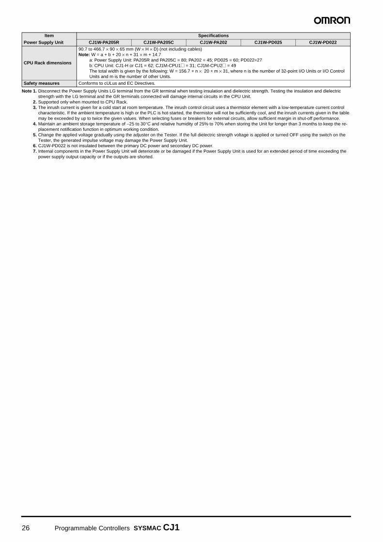
Note 1. Disconnect the Power Supply Units LG terminal from the GR terminal when testing insulation and dielectric strength. Testing the insulation and dielectric strength with the LG terminal and the GR terminals connected will damage internal circuits in the CPU Unit.
2. Supported only when mounted to CPU Rack.3. The inrush current is given for a cold start at room temperature. The inrush control circuit uses a thermistor element with a low-temperature current control
characteristic. If the ambient temperature is high or the PLC is hot-started, the thermistor will not be sufficiently cool, and the inrush currents given in the table may be exceeded by up to twice the given values. When selecting fuses or breakers for external circuits, allow sufficient margin in shut-off performance.
4. Maintain an ambient storage temperature of −25 to 30°C and relative humidity of 25% to 70% when storing the Unit for longer than 3 months to keep the re-placement notification function in optimum working condition.
5. Change the applied voltage gradually using the adjuster on the Tester. If the full dielectric strength voltage is applied or turned OFF using the switch on the Tester, the generated impulse voltage may damage the Power Supply Unit.
6. CJ1W-PD022 is not insulated between the primary DC power and secondary DC power.7. Internal components in the Power Supply Unit will deteriorate or be damaged if the Power Supply Unit is used for an extended period of time exceeding the
power supply output capacity or if the outputs are shorted.
CPU Rack dimensions
90.7 to 466.7 × 90 × 65 mm (W × H × D) (not including cables)Note: W = a + b + 20 × n + 31 × m + 14.7
a: Power Supply Unit: PA205R and PA205C = 80; PA202 = 45; PD025 = 60; PD022=27b: CPU Unit: CJ1-H or CJ1 = 62; CJ1M-CPU1@ = 31; CJ1M-CPU2@ = 49The total width is given by the following: W = 156.7 + n × 20 + m × 31, where n is the number of 32-point I/O Units or I/O Control Units and m is the number of other Units.
Safety measures Conforms to cULus and EC Directives.
Item Specifications
Power Supply Unit CJ1W-PA205R CJ1W-PA205C CJ1W-PA202 CJ1W-PD025 CJ1W-PD022
26 Programmable Controllers SYSMAC CJ1

CPU Units
CJ1G/H/H-R CPU Units CJ1M CPU Units CJ1G Loop-con-trol CPU UnitsCJ1-H-R CPU Units CJ1H-H CPU Units CJ1G-H CPU Units Without Built-in I/O With Built-in I/O
Model CJ1H-CPU@@H-R CJ1H-CPU@@H CJ1G-CPU@@H CJ1M-CPU1@ CJ1M-CPU2@ CJ1G-CPU@@P(-GTC)
Item
Appear-ance
LD instruction processing speed
0.016 µs 0.02 µs 0.04 µs 0.1 µs 0.1 µs 0.04 µs
Program capacity 250K to 30K steps 250K to 60K steps 60K to 10K steps 20K to 5K steps 20K to 5K steps 60K to 10K steps
Data memory capac-ity
448K to 64K words 448K to 128K words 128K to 64K words 32K words 32K words 128K to 64K words
I/O bits 2560 bits 2560 bits 1280 to 960 bits 640 to 160 bits 640 to 160 bits 1280 to 960 bits
Width 62 mm 62 mm 62 mm 31 mm 49 mm 69 mm
Built-in I/O --- 16 bits ---
Loop control --- 50 to 300 blocks
Programmable Controllers SYSMAC CJ1 27

Specifications
Common SpecificationsItem Specifications
Control method Stored program
I/O control method Cyclic scan and immediate processing are both possible.
Programming Ladder diagram
CPU processing mode
CJ1-H CPU Units: Normal Mode, Parallel Processing Mode with Asynchronous Memory Access, Parallel Processing Mode with Synchronous Memory Access, or Peripheral Servicing Priority Mode
CJ1M CPU Units: Normal Mode or Peripheral Servicing Priority ModeCJ1 CPU Units: Normal Mode or Peripheral Servicing Priority Mode
Instruction length 1 to 7 steps per instruction
Ladder instructions Approx. 400 (3-digit function codes)
Execution time
CJ1-H-R CPU UnitsBasic instructions:Special instructions:
CJ1-H CPU Units:Basic instructions: Special instructions:
CJ1M CPU Units (CPU12/13/22/23): Basic instructions: Special instructions:
CJ1M CPU Units (CPU11/21): Basic instructions: Special instructions:
CJ1 CPU Units:Basic instructions: Special instructions:
0.016 µs min.0.048 µs min.
0.02 µs min.0.06 µs min.
0.10 µs min.0.15 µs min.
0.10 µs min.0.15 µs min.
0.08 µs min.0.12 µs min.
Overhead time
CJ1-H-R CPU Units:Normal mode: Parallel processing:
CJ1-H CPU Units: 0.3 ms minNormal mode: Parallel processing:
CJ1M CPU Units (CPU12/13/22/23): CJ1M CPU Units (CPU11/12): CJ1 CPU Units:
0.13 ms min.0.28 ms min.
0.3 ms min.0.3 ms min.0.5 ms min.0.7 ms min.0.5 ms min.
Unit connection method No Backplane: Units connected directly to each other.
Mounting method DIN Track (screw mounting not possible)
Maximum number of connectable Units
• CJ1-H and CJ1 CPU Units: Per CPU or Expansion Rack: 10 Units including Basic I/O Units, Special I/O Units, and CPU Bus Units.Total per PLC: 10 Units on CPU Rack and 10 Units each on 3 Expansion Racks = 40 Units total
• CJ1M CPU Units:Total of 20 Units in the System, including 10 Units on CPU Rack and 10 Units on one Expansion Rack.
Maximum number of Expansion Racks
• CJ1-H and CJ1 CPU Units: 3 max. (An I/O Control Unit is required on the CPU Rack and an I/O Interface Unit is required on each Expansion Rack.)
• CJ1M CPU Units (CPU 13/23 only): 1 max. (An I/O Control Unit is required on the CPU Rack and an I/O Interface Unit is required on the Expansion Rack.)
• CJ1M CPU Units (CPU11/12/21/22): Expansion is not possible.
Number of tasks
288 (cyclic tasks: 32, interrupt tasks: 256)With CJ1-H or CJ1M CPU Units, interrupt tasks can be defined as cyclic tasks called extra cyclic tasks. Including these, up to 288 cyclic tasks can be used.Note 1. Cyclic tasks are executed each cycle and are controlled with TKON(820) and TKOF(821) instructions.
2. The following 4 types of interrupt tasks are supported.Power OFF interrupt tasks: 1 max.Scheduled interrupt tasks: 2 max.I/O interrupt tasks: 32 max.External interrupt tasks: 256 max.
Interrupt types
Scheduled Interrupts: Interrupts generated at a time scheduled by the CPU Units built-in timer. (See note. 1)I/O Interrupts: Interrupts from Interrupt Input Units.Power OFF Interrupts (See note 2.): Interrupts executed when the CPU Units power is turned OFF.External I/O Interrupts: Interrupts from the Special I/O Units or CPU Bus Units.Note 1. CJ1-H and CJ1 CPU Units: Scheduled interrupt time interval is either 1 ms to 9,999 ms or 10 ms to 99,990
ms, in units of 1 ms or 10 ms. CJ1M CPU Units: In addition to the above, a scheduled interrupt time interval of 0.5 ms to 999.9 ms, in unitsof 0.1 ms, is also possible.
2. Not supported when the CJ1W-PD022 Power Supply Unit is mounted.
Calling subroutines from more than one task
• CJ1-H CPU Units: Supported (called global subroutines).• CJ1 CPU Units: Not supported.
CIO (Core I/O) Area
I/O Area
2,560: CIO 000000 to CIO 015915 (160 words from CIO 0000 to CIO 0159)The setting of the first word can be changed from the default (CIO 0000) so that CIO 0000 to CIO 0999 can be used.I/O bits are allocated to Basic I/O Units.
The CIO Area can be used as work bits if the bits are not used as shown here.
Link Area3,200 (200 words): CIO 10000 to CIO 119915 (words CIO 1000 to CIO 1199)Link bits are used for data links and are allocated to Units in Controller Link Systems.
28 Programmable Controllers SYSMAC CJ1

CIO (Core I/O) Area
CPU Bus Unit Area 6,400 (400 words): CIO 150000 to CIO 189915 (words CIO 1500 to CIO 1899)CPU Bus Unit bits store the operating status of CPU Bus Units. (25 words per Unit, 16 Units max.)
The CIO Area can be used as work bits if the bits are not used as shown here.
Special I/O Unit Area
15,360 (960 words): CIO 200000 to CIO 295915 (words CIO 2000 to CIO 2959)Special I/O Unit bits are allocated to Special I/O Units. (10 words per Unit, 96 Units max.)
Serial PLC Link Area (CJ1M CPU Units only)
1,440 (90 words): CIO 310000 to CIO 318915 (words CIO 3100 to CIO 3189)
DeviceNet Area
9,600 (600 words): CIO 320000 to CIO 379915 (words CIO 3200 to CIO 3799)DeviceNet bits are allocated to Slaves for DeviceNet Unit remote I/O communications when the Master function is used with fixed allocations.
The following words are allocated to the Master function even when the DeviceNet Unit is used as a Slave.
Internal I/O Area
4,800 (300 words): CIO 120000 to CIO 149915 (words CIO 1200 to CIO 1499)37,504 (2,344 words): CIO 380000 to CIO 614315 (words CIO 3800 CIO 6143)These bits in the CIO Area are used as work bits in programming to control program execution. They cannot be used for external I/O.
Work Area8,192 bits (512 words): W00000 to W51115 (W000 to W511)Controls the programs only. (I/O from external I/O terminals is not possible.)Note: When using work bits in programming, use the bits in the Work Area first before using bits from other areas.
Holding Area
8,192 bits (512 words): H00000 to H51115 (H000 to H511) Holding bits are used to control the execution of the pro-gram, and maintain their ON/OFF status when the PLC is turned OFF or the operating mode is changed.Note: The Function Block Holding Area words are allocated from H512 to H1535. These words can be used only for
the function block instance area (internally allocated variable area).
Auxiliary AreaRead only: 7,168 bits (448 words): A00000 to A44715 (words A000 to A447)Read/write: 8,192 bits (512 words): A44800 to A95915 (words A448 to A959)Auxiliary bits are allocated specific functions.
Temporary Area16 bits (TR0 to TR15)Temporary bits are used to temporarily store the ON/OFF execution conditions at program branches.
Timer Area 4,096: T0000 to T4095 (used for timers only)
Counter Area 4,096: C0000 to C4095 (used for counters only)
DM Area
32 Kwords: D00000 to D32767Used as a general-purpose data area for reading and writing data in word units (16 bits). Words in the DM Areamaintain their status when the PLC is turned OFF or the operating mode is changed.Internal Special I/O Unit DM Area: D20000 to D29599 (100 words × 96 Units)Used to set parameters for Special I/O Units.CPU Bus Unit DM Area: D30000 to D31599 (100 words × 16 Units) Used to set parameters for CPU Bus Units.
EM Area (CJ1-H and CJ1 CPU Units only)
32 Kwords per bank, 7 banks max.: E0_00000 to E6_32767 max. (depending on model of CPU Unit)Used as a general-purpose data area for reading and writing data in word units (16 bits). Words in the EM Area maintain their status when the PLC is turned OFF or the operating mode is changed.The EM Area is divided into banks, and the addresses can be set by either of the following methods.Changing the current bank using the EMBC(281) instruction and setting addresses for the current bank.Setting bank numbers and addresses directly.EM data can be stored in files by specifying the number of the first bank.
Index Registers
IR0 to IR15Store PLC memory addresses for indirect addressing. Index registers can be used independently in each task. One register is 32 bits (2 words).• CJ1-H and CJ1M CPU Units: Setting to use index registers either independently in each task or to share them
between tasks.• CJ1 CPU Units: Index registers used independently in each task.
Task Flag Area
32 (TK0000 to TK0031)Task Flags are read-only flags that are ON when the corresponding cyclic task is executable and OFF when the corresponding task is notexecutable or in standby status.
Trace Memory 4,000 words (trace data: 31 bits, 6 words)
File Memory
• Memory Cards: Compact flash memory cards can be used (MS-DOS format).• EM file memory (CJ1-H and CJ1 CPU Units only): Part of the EM Area can be converted to file memory (MS-
DOS format).• OMRON Memory Cards can be used.
Item Specifications
Fixed allocation setting 1 Outputs: CIO 3200 to CIO 3263
Inputs: CIO 3300 to CIO 3363
Fixed allocation setting 2 Outputs: CIO 3400 to CIO 3463
Inputs: CIO 3500 to CIO 3563
Fixed allocation setting 3 Outputs: CIO 3600 to CIO 3663
Inputs: CIO 3700 to CIO 3763
Fixed allocation setting 1 Outputs: CIO 3370 (Slave to Master)Inputs: CIO 3270 (Master to Slave)
Fixed allocation setting 2 Outputs: CIO 3570 (Slave to Master)
Inputs: CIO 3470 (Master to Slave)
Fixed allocation setting 3 Outputs: CIO 3770 (Slave to Master)
Inputs: CIO 3670 (Master to Slave)
Programmable Controllers SYSMAC CJ1 29

Function SpecificationsItem Specifications
Constant cycle time1 to 32,000 ms (Unit: 1 ms)Note: When a Parallel Processing Mode is used for a CJ1-H CPU Unit, the cycle time for executing instructions is constant.
Cycle time monitoringPossible (Unit stops operating if the cycle is too long): 10 to 40,000 ms (Unit: 10 ms)Note: When a Parallel Processing Mode is used for a CJ1-H CPU Unit, the instruction execution cycle is monitored. CPU Unit operation
will stop if the peripheral servicing cycle time exceeds 2 s (fixed).
I/O refreshingCyclic refreshing, immediate refreshing, refreshing by IORF(097).Note: ORF(097) refreshes I/O bits allocated to Basic I/O Units and Special I/O Units. With the CJ1-H and CJ1M CPU Units, the CPU BUS
UNIT I/O REFRESH (DLNK(226)) instruction can be used to refresh bits allocated to CPU Bus Units in the CIO and DM Areas.
Timing of special refreshing for CPU Bus Units
Data links for Controller Link Units and SYSMAC LINK Units, remote I/O for DeviceNet Units, and other special refreshing for CPU Bus Units is performed at the following times:• CJ1 and CJ1M CPU Units: I/O refresh period• CJ1-H CPU Units: I/O refresh period and when the CPU BUS UNIT I/O REFRESH (DLNK(226)) instruction is executed.
I/O memory holding when changing operating modes
Depends on the ON/OFF status of the IOM Hold Bit in the Auxiliary Area.
Load OFF All outputs on Output Units can be turned OFF when the CPU Unit is operating in RUN, MONITOR, or PROGRAM mode.
Timer/Counter PV refresh method
CJ1-H and CJ1M CPU Units: BCD or binary (CX-Programmer Ver. 3.0 or higher).CJ1 CPU Units: BCD only.
Input response time setting
Time constants can be set for inputs from Basic I/O Units.The time constant can be increased to reduce the influence of noise and chattering or it can be decreased to detect shorter pulses on the inputs.
Mode setting at power-up
Possible.Note: By default, the CPU Unit will start in RUN mode if a Programming Console is not connected.
Flash memory (CJ1-H and CJ1M CPU Units only)
• The user program and parameter area data (e.g., PLC Setup) are always backed up automatically in flash memory. (automatic backupand restore.)
• CPU Units with unit version 3.0 or later only:When downloading projects from CX-Programmer Ver. 5.0 or higher, symbol table files (including CX-Programmer symbol names, I/O comments), comment files (CX-Programmer rung comments, other comments), and program index files (CXProgrammer section names, section comments, or program comments) are stored in comment memory within the flash memory.
Memory Card functions
Automatically reading programs (autoboot) from the Memory Card when the power is turned ON.
Possible.
Program replacement during PLC operation Possible.
Format in which data is stored in Memory CardUser program: Program file format PLC Setup and other parameters:Data file format I/O memory: Data file format (binary format), text format, or CSV format
Functions for which Memory Card read/write is supported
User program instructions, Programming Devices (including CX-Programmer and Programming Consoles), Host Link computers, AR Area control bits, easy backup operation
Filing Memory Card data and the EM (Extended Data Memory) Area can be handled as files.
DebuggingControl set/reset, differential monitoring, data tracing (scheduled, each cycle, or when instruction is executed), instruction error tracing, storing location generating error when a program error occurs.
Online editingUser programs can be overwritten in program-block units when the CPU Unit is in MONITOR or PROGRAM mode.This function is not available for block programming areas.With the CX-Programmer, more than one program block can be edited at the same time.
Program protectionOverwrite protection: Set using DIP switch.Copy protection: Password set using CX-Programmer or Programming Consoles.
Error checkUser-defined errors (i.e., user can define fatal errors and non-fatal errors)The FPD(269) instruction can be used to check the execution time and logic of each programming block.Note: FAL and FALS instructions can be used with the CJ1-H and CJ1M CPU Units to simulate errors.
Error logUp to 20 errors are stored in the error log. Information includes the error code, error details, and the time the error occurred.Note: A CJ1-H or CJ1M CPU Unit can be set so that user-defined FAL errors are not stored in the error log.
Serial communica-tions
Built-in peripheral port: Programming Device (including Programming Console) connections, Host Links, NT LinksBuilt-in RS-232C port: Programming Device (excluding Programming Console) connections, Host Links, no-protocol communications, NT Links
Serial Communications Unit (sold separately): Protocol macros, Host Links, NT Links
Clock
Provided on all models.
Note: Used to store the time when power is turned ON and when errors occur.
Power OFF detection time
AC Power Supply Unit: 10 to 25 ms (not fixed)DC Power Supply Unit PD025: 2 to 5 ms; PD022: 2 to 10 ms
Power OFF detection delay time
0 to 10 ms (user-defined, default: 0 ms)Note: Not supported when the CJ1W-PD022 Power Supply Unit is mounted.
Memory protection
Held Areas: Holding bits, contents of Data Memory and Extended Data Memory, and status of the counter Completion Flags and present values.Note: If the IOM Hold Bit in the Auxiliary Area is turned ON, and the PLC Setup is set to maintain the IOM Hold Bit status when power to
the PLC is turned ON, the contents of the CIO Area, the Work Area, part of the Auxiliary Area, timer Completion Flag and PVs, IndexRegisters, and the Data Registers will be saved for up to 20 days.
Sending commands to a Host Link computer
FINS commands can be sent to a computer connected via the Host Link System by executing Network Communications Instructions from the PLC.
Accuracy: Ambient temperature Monthly error
55°C −3.5 min to +0.5 min
25°C −1.5 min to +1.5 min
0°C −3 min to +1 min
30 Programmable Controllers SYSMAC CJ1

Functions Added for New Unit VersionsRefer to the datasheet (Cat. No. P504).
Relations between CX-Programmer Versions and Unit Versions of CPU UnitsRefer to the datasheet (Cat. No. P504).
Remote program-ming and monitoring
Host Link communications can be used for remote programming and remote monitoring through a Controller Link System or Ethernet network.
Communicating across networklevels
Remote programming and monitoring from Support Software and FINS message communications can be performed across different network levels, even for different types of network.Pre-Ver. 2.0: Three levelsVersion 2.0 or later: Eight levels for Controller Link and Ethernet networks (See note.), three levels for other networks.Note: To communicate across eight levels, the CX-Integrator or the CX-Net in Programmer version 4.0 or higher must be used to set the
routing tables.
Storing comments in CPU Unit
I/O comments can be stored as symbol table files in the Memory Card, EM file memory, or comment memory (see note).Note: Comment memory is supported for CX-Programmer version 5.0 or higher and CS/CJ-series CPU Units with unit version 3.0 or later
only.
Program checkProgram checks are performed at the beginning of operation for items such as no END instruction and instruction errors.CX-Programmer can also be used to check programs.
Control output signals
RUN output: The internal contacts will turn ON (close) while the CPU Unit is operating (CJ1W-PA205R).
Battery life• Battery Set for CJ1-H and CJ1 CPU Units: CPM2A-BAT01• Battery Set for CJ1M CPU Units: CJ1W-BAT01
Self-diagnostics CPU errors (watchdog timer), I/O bus errors, memory errors, and battery errors.
Other functions Storage of number of times power has been interrupted. (Stored in A514.)
Item Specifications
Programmable Controllers SYSMAC CJ1 31

Additional CJ1M-CPU21/22/23 Specifications
• CJ1M-CPU2@ CPU Units have 10 built-in inputs and 6 built-in outputs.
• The 10 inputs can be used as general-purpose inputs, interrupt inputs, quick-response inputs, high-speed counters, or origin search
origin input signals.
• The 6 outputs can be used as general-purpose outputs, pulse outputs, or origin search deviation counter reset outputs.
Data Area Allocations for Built-in I/O
Note: CJ1M-CPU21 CPU Units have one PWM output only and do not have PWM output 1.
Built-in Input Specifications Interrupt Inputs and Quick-response Inputs
High-speed Counter Inputs
I/O Code IN 0 IN 1 IN 2 IN 3 IN 4 IN 5 IN 6 IN 7 IN 8 IN 9 OUT 0 OUT 1 OUT 2 OUT 3 OUT 4 OUT 5
Address 2960 2961
Bit 0 1 2 3 4 5 6 7 8 9 0 1 2 3 4 5
Inputs
General purpose inputs
General purpose input 0
General purpose input 1
General purpose input 2
General purpose input 3
General pur-pose input 4
General pur-pose input 5
General pur-pose input 6
General pur-pose input 7
General pur-pose input 8
General pur-pose input 9
--- --- --- --- --- ---
Interrupt inputs Interrupt input 0
Interrupt input 1
Interrupt input 2
Interrupt input 3
--- --- --- --- --- --- --- --- --- --- --- ---
Quick response inputs
Quick response input 0
Quick response input 1
Quick response input 2
Quick response input 3
--- --- --- --- --- --- --- --- --- --- --- ---
Highspeed counters --- ---
High-speed counter 1 (phase- Z/reset)
High-speed counter 0 (phase- Z/reset)
--- ---
High-speed counter 1 (phase-A, incre-ment, or count input)
High-speed counter 1 (phase-B, dec-rement, or direc-tion input)
High-speed counter 0 (phase-A, incre-ment, or count input)
High-speed counter 0 (phase-B, dec-rement, or direc-tion input)
--- --- --- --- --- ---
Out-puts
General-pur-pose outputs --- --- --- --- --- --- --- --- --- ---
Gen-eral-pur-pose output 0
Gen-eral- pur-pose output 1
Gen-eral-pur-pose output 2
Gen-eral-pur-pose output 3
Gen-eral-pur-pose output 4
Gen-eral-pur-pose output 5
Pulse out-puts
CW/CCW outputs
--- --- --- --- --- --- --- --- --- ---Pulse output 0 (CW)
Pulse output 0 (CCW)
Pulse output 1 (CW)
Pulse output 1 (CCW)
--- ---
Pulse + direction outputs
--- --- --- --- --- --- --- --- --- ---
Pulse output 0 pulse)
Pulse output 1 (pulse)
Pulse output 0 (direc-tion)
Pulse output 1 (direc-tion)
--- ---
Variable duty ratio outputs
--- --- --- --- --- --- --- --- --- --- --- --- --- ---
PWM(891) out-put 0
PWM(891) out-put 1
Origin search
Origin search 0 (Origin Input Signal)
Origin search 0 (Origin Proxim-ity Input Signal)
Origin search 1 (Origin Input Signal)
Origin search 1 (Origin Proxim-ity Input Signal)
Origin search 0 (Posi-tioning Com-pleted Signal)
Origin search 1 (Posi-tioning Com-pleted Signal)
--- --- --- --- --- --- --- ---
Origin search 0 (Error Counter Reset Output)
Origin search 1 (Error Counter Reset Output)
Item Specifications
No. of interrupt inputs/quick-response inputs
4 total
Input inter-rupts
Direct (Input Interrupt) Mode
Execution of an interrupt task is started at the interrupt input's rising or falling edge. Interrupt numbers 140 to 143 are used (fixed).Response time from meeting input condition to start of interrupt task execution: 93 µs min.
High-speed Counter Mode
Rising or falling edges of the interrupt are counted using either an incrementing or decrementing counter, and an interrupt task is started when the input count reaches the set value. Interrupt numbers 140 to 143 are used (fixed).I/O response frequency: 1 kHz
Quick-response inputsSignals that are shorted than the cycle time (30 µs min.) can be read and treated the same as signals that are one for more than one cycle time.
Item Specifications
Number of high-speed counters
2 (High-speed counters 0 and 1)
Pulse input mode (Selected in PLC Setup)
Differential phase inputs (phase-A, phase-B, and phase-Z input)
Up/down inputs (up inputs, down inputs, reset inputs)
Pulse + direction inputs (pulse inputs, direction inputs, reset inputs)
Increment inputs (increment inputs, reset inputs)
Re-sponse frequency
Line-driver inputs
50 kHz 100 kHz 100 kHz 100 kHz
24-V DC inputs 30 kHz 60 kHz 60 kHz 60 kHz
Counting mode Linear mode or Ring mode (Select in the PLC Setup.)
32 Programmable Controllers SYSMAC CJ1

Built-in Output Specifications Position Control and Speed Control
Variable-duty Pulse Outputs (PWM)
Note: CJ1M CPU Unit Ver. 2.0 or later only. (0% to 100%, set in 1% units for Pre-Ver. 2.0 CPU Units.)
Count valueLinear mode: 80000000 to 7FFFFFFF hexRing mode: 00000000 to Ring SV(The Ring SV is set in the PLC Setup and the setting range is 00000001 to FFFFFFFF hex.)
High-speed counter PV storage locations
High-speed counter 0: A271 (leftmost 4 digits) and A270 (rightmost 4 digits)High-speed counter 1: A273 (leftmost 4 digits) and A272 (rightmost 4 digits)Target value comparison interrupts or range comparison interrupts can be executed based on these PVs.Note: The PVs are refreshed in the overseeing processes at the beginning of each cycle. Use the PRV(881) instruction to read the most recent
PVs.
Control method
Target value comparison
Up to 48 target values and corresponding interrupt task numbers can be registered.
Range compar-ison
Up to 8 ranges can be registered, with an upper limit, lower limit, and interrupt task number for each.
Counter reset methodPhase-Z + Software reset: Counter is reset when phase-Z input goes ON while Reset Bit is ON.Software reset: Counter is reset when Reset Bit goes ON.Reset Bits: High-speed Counter 0 Reset Bit is A53100, Counter 1 Reset Bit is A53101.
Item Specifications
Item Specifications
Number of pulse outputs 2 (Pulse output 0 or 1)
Output frequency 1 Hz to 100 kHz (1-Hz units from 1 to 100 Hz, 10-Hz units from 100 Hz to 4 kHz, and 100-Hz units from 4 to 100 kHz)
Frequency acceleration and deceleration rates
Set in 1 Hz units for acceleration/deceleration rates from 1 Hz to 2 kHz (every 4 ms). The acceleration and deceleration rates can be set separately only with PLS2(887).
Changing SVs during in-struction execution
The target frequency, acceleration/deceleration rate, and target position can be changed. Changes to the target frequency and acceleration/deceleration rate must be made at constant speed.
Pulse output method CW/CCW inputs or Pulse + direction inputs
Number of output pulsesRelative coordinates: 00000000 to 7FFFFFFF hex (Each direction accelerating or decelerating: 2,147,483,647)Absolute coordinates: 80000000 to 7FFFFFFF hex (−2,147,483,648 to 2,147,483,647)
Instruction used for origin searches and returns
ORIGIN SEARCH (ORG(889)): Origin search and origin return operations according to set parameters
Instructions used for posi-tion and speed control
PULSE OUTPUT (PLS2(887)): Trapezoidal output control with separate acceleration and deceleration rate SET PULSES (PULS(886)): Setting the number of pulses for pulse output
SPEED OUTPUT (SPED(885)):Pulse output without acceleration or deceleration (Number of pulses must be set in advance with PULS(886) for position control.)
ACCELERATION CONTROL (ACC(888)): Changes frequency or pulse output with acceleration and deceleration MODE CONTROL (INI(880)): Stopping pulse output
Pulse output PV's storage location
The following Auxiliary Area words contain the pulse output PVs:Pulse output 0: A277 (leftmost 4 digits) and A276 (rightmost 4 digits)Pulse output 1: A279 (leftmost 4 digits) and A278 (rightmost 4 digits)The PVs are refreshed during regular I/O refreshing. PVs can be read to user-specified words with the PRV(881) instruction.
Item Specifications
Number of PWM outputsCJ1M-CPU22/23: 2 (PWM output 0 or 1)CJ1M-CPU21: 1 (PWM output 0)
Duty ratio 0% to 100%, set in 0.1% units (See note.)
Frequency 0.1 Hz to 999.9 Hz, Set in 0.1 Hz units.
Instruction PULSE WITH VARIABLE DUTY RATIO (PWM(891)): Sets duty ratio and outputs pulses.
Programmable Controllers SYSMAC CJ1 33

Hardware Specifications Input Specifications
Input Circuit Configuration
General-purpose Output Specifications for Transistor Outputs (Sinking)
Pulse Output Specifications (OUT0 to OUT3)
Item Specifications
Number of inputs 10 inputs
Input method 24-V DC inputs or line driver (wiring changed to select)
Input voltage specifica-tions
24 V DC Line driver
IN0 to IN5 IN6 to IN9 IN0 to IN5 IN6 to IN9
Input voltage 20.4 to 26.4 V DCVRS-422A or RS-422 line driver (conforming to AM26LS31), Power supply voltage of 5 V ± 5%
Input impedance 3.6 kΩ 4.0 kΩ ---
Input current (typical) 6.2 mA 4.1 mA 13 mA 10 mA
Minimum ON voltage 17.4 V DC/3 mA min. ---
Maximum OFF voltage 5.0 V DC/1 mA max. ---
Response speed (for general-pur-pose inputs)
ON re-sponse time
Default setting: 8 ms max. (The input time constant can be set to 0 ms, 0.5 ms, 1 ms, 2 ms, 4 ms, 8 ms, 16 ms, or 32 ms in the PLC Setup.)
OFF re-sponse time
Default setting: 8 ms max. (The input time constant can be set to 0 ms, 0.5 ms, 1 ms, 2 ms, 4 ms, 8 ms, 16 ms, or 32 ms in the PLC Setup.)
Item Specifications
Input IN0 to IN5 IN6 to IN9
Circuit configuration
Item Specifications
Output OUT0 to OUT3 OUT4 to OUT5
Rated voltage 5 to 24 V DC
Allowable voltage range 4.75 to 26.4 V DC
Max. switching capacity 0.3 A/output; 1.8 A/Unit
Number of circuits 6 outputs (6 outputs/common)
Max. inrush current 3.0 A/output, 10 ms max.
Leakage current 0.1 mA max.
Residual voltage 0.6 V max.
ON delay 0.1 mA max.
OFF delay 0.1 mA max.
Fuse None
External power supply 10.2 to 26.4 V DC 50 mA min.
Circuit configuration
Item Specifications
Max. switching capacity 30 mA, 4.75 to 26.4 V DC
Min. switching capacity 7 mA, 4.75 to 26.4 V DC
Max. output frequency 100 kHz
Output waveform
24 V
LD+
0V/LD−
100 Ω
1000 pF
100 Ω
750 Ω
3.6 kΩ
Internal circuits
24 V
LD+
1000 pF1.5 kΩ
4.0 kΩ
0V/LD−100 Ω
Internal circuits
100 Ω
OUT0
COM
Lowvoltagecircuit
+V
Inte
rnal
circ
uits
OUT3to
OUT4
COM
OUT5
Lowvoltagecircuit
+V
Inte
rnal
circ
uits
to
90%
10%
2 µs min.4 µs min.
ON
OFF
34 Programmable Controllers SYSMAC CJ1

CJ1G-CPU@@P (Loop-control CPU Units) SpecificationsIn addition to engines for executing sequence control, Loop-control CPU Units (CJ1G-CPU@@P) have built-in engines for controlling analog quantities (such as tem-peratures, pressure and flow rate), thus enabling high-speed sequence control and advanced high-speed control of analog quantities in a single Unit.
CPU Element (Sequence Control)
Note: These Loop-control CPU Units support gradient temperature control, a technology for uniform in-plane control of temperatures of plane-shaped objects (e.g.,multi-point control of surface temperatures based on a multi-point heater). For details, please contact an OMRON representative.
Loop Controller Element (Loop Control)
Name I/O bits Program capacity DM words EM words Model
Loop-control CPU Unit
1,280 bits60K steps
32K words
32K words × 3 banksE0_00000 to E2_32767
CJ1G-CPU45P
CJ1G-CPU45P-GTC (See note.)
30K steps32K words × 1 bank
E0_00000 to E0_32767
CJ1G-CPU44P
960 bits20K steps CJ1G-CPU43P
20K steps CJ1G-CPU42P
Item Model CJ1G-CPU42P CJ1G-CPU43P CJ1G-CPU44P CJ1G-CPU45P(-GTC)
Operation method Function block method
Operation cycle0.01, 0.02, 0.05, 0.1, 0.2, 0.5, 1, or 2 s (default: 1 s)Can be set for each function block.
Number of func-tion blocks
Analog operations
Control and opera-tion blocks
50 blocks max. 300 blocks max.
Sequence control
Step ladder program blocks
20 blocks max.2,000 commands total
200 blocks max. 4,000 commands total
I/O blocks
Field terminal blocks
30 blocks max. 40 blocks max.
User link tables 2,400 data items max.
Batch allocation HMI function, allocated 1 EM Area bank
System Common block Single block
Method for creating and transferring function blocks
Created using CX-Process Tool (order separately) and transferred to Loop Controller.
Control method
PID control method PID with 2 degrees of freedom (with autotuning)
Control combinationsAny of the following function blocks can be combined:Basic PID control, cascade control, feed-forward control, sample PI control, Smith dead time compensation control, PID control with differential gap, override control, program control, time-proportional control, etc.
AlarmsPID block internal alarms 4 PV alarms (upper upper-limit, upper limit, lower limit, lower lower-limit) and 1 deviation alarm per PID block.
Alarm blocks High/low alarm blocks, deviation alarm blocks
Programmable Controllers SYSMAC CJ1 35

Checking Current Consumption and Power Consumption
After selecting a Power Supply Unit based on considerations such as the power supply voltage, calculate the current and power require-ments for each Rack.
Condition 1: Current RequirementsThere are two voltage groups for internal power consumption: 5 V and 24 V.Current consumption at 5 V (internal logic power supply) Current consumption at 24 V (relay driving power supply)Condition 2: Power Requirements
For each Rack, the upper limits are determined for the current and power that can be provided to the mounted Units. Design the systemso that the total current consumption for all the mounted Units does not exceed the maximum total power or the maximum current sup-plied for the voltage groups shown in the following tables. The maximum current and total power supplied for CPU Racks and Expansion Racks according to the Power Supply Unit model areshown below.
Note 1. For CPU Racks, include the CPU Unit current and power consumption in the calculations. When expanding, also include the current and power consumption of the I/O Control Unit in the calculations.
2. For Expansion Racks, include the I/O Interface Unit current and power consumption in the calculations.
Conditions 1 and 2 below must be satisfied.
Condition 1: Maximum Current
(1) Total Unit current consumption at 5 V ≤ (A) value
(2) Total Unit current consumption at 24 V ≤ (B) value
Condition 2: Maximum Power
(1) × 5 V + (2) × 24 V ≤ (C) value
Example: Calculating Total Current and Power ConsumptionExample: When the Following Units are Mounted to a CJ-series CPU Rack Using a CJ1W-PA202 Power Supply Unit
Note: For details on Unit current consumption, refer to Ordering Information.
Using the CX-Programer to Display Current Consumption and WidthCPU Rack and Expansion Rack current consumption and width can be displayed by selecting Current Consumption and Width from theOptions Menu in the CS/CJ/CP Table Window. (The width can be displayed for the CJ/CP Series only.) If the capacity of the Power Sup-ply Unit is exceeded, it will be displayed in red characters. For details, refer to the CX-Programmer Operation Manual (Cat. No. W446).
Example:
Power Supply UnitsMax. current supplied Max. total
power sup-plied5 V
24 V (relay driv-ing current)
CJ1W-PA205C 5.0 A 0.8 A 25 WCJ1W-PA205R 5.0 A 0.8 A 25 WCJ1W-PA202 2.8 A 0.4 A 14 WCJ1W-PD025 5.0 A 0.8 A 25 WCJ1W-PD022 2.0 A 0.4 A 19.6 W
Unit type Model QuantityVoltage group
5 V 24 V
CPU Unit CJ1G-CPU45H 1 0.910 A ---
I/O Control Unit CJ1W-IC101 1 0.020 A ---
Basic I/O Units (Input Units)CJ1W-ID211 2 0.080 A ---
CJ1W-ID231 2 0.090 A ---
Basic I/O Units (Output Units) CJ1W-OC201 2 0.090 A 0.048 A
Special I/O Unit CJ1W-DA041 1 0.120 A ---
CPU Bus Unit CJ1W-CLK23 1 0.350 A ---
Current consumptionTotal
0.910 + 0.020 + 0.080 × 2 + 0.090 ×
2 + 0.090 × 2 + 0.120 + 0.3500.048 A × 2
Result 1.92 A (≤ 2.8 A) 0.096 A (≤ 0.4 A)
Power consumptionTotal 1.92 × 5 V = 9.60 W 0.096 A × 24 V = 2.304 W
Result 9.60 + 2.304 = 11.904 W (≤ 14 W)
Power Supply Unit model
Current consumption at 5 V Current
consumption at 26 V/24 V
Total current consumption
Long-distance expansion
Width
36 Programmable Controllers SYSMAC CJ1
Ordering Information
Basic Configuration Units .................................................................................38
Programming Devices...................................................................................... 42
Optional Products and Maintenance Products ................................................45
DIN Track Accessories .....................................................................................45
Basic I/O Units ..................................................................................................46
Special I/O Units and CPU Bus Units ...............................................................50
International Standards
• The standards indicated in the "Standards" column arethose current for UL, CSA, cULus, cUL, NK, and Lloydstandards and EC Directives as of the end of January2008. The standards are abbreviated as follows: U: UL,U1: UL Class I Division 2 Products for HazardousLocations, C: CSA, UC: cULus, UC1: cULus Class IDivision 2 Products for Hazardous Locations, CU: cUL,N: NK, L: Lloyd, and CE: EC Directives.
• Ask your OMRON representative for the conditionsunder which the standards were met.
EC DirectivesThe EC Directives applicable to PLCs include the EMC Di-rectives and the Low Voltage Directive. OMRON complieswith these directives as described below. EMC Directives
Applicable StandardsEMI: EN61000-6-4, EN61131-2EMS: EN61000-6-2, EN61131-2PLCs are electrical devices that are incorporated in ma-chines and manufacturing installations. OMRON PLCsconform to the related EMC standards so that the devic-es and machines into which they are built can more eas-ily conform to EMC standards. The actual PLCs havebeen checked for conformity to EMC standards. Wheth-er thesestandards are satisfied for the actual system, however,must be checked by the customer.EMC-related performance will vary depending on theconfiguration, wiring, and other conditions of the equip-ment or control panel in which the PLC is installed. Thecustomer must, therefore, perform final checks to con-firm that the overall machine or device conforms to EMCstandards.
Low Voltage DirectiveApplicable Standard:EN61131-2VDC must satisfy the appropriate safety requirements.With PLCs, this applies to Power Supply Units and I/OUnits that operate in these voltage ranges.These Units have been designed to conform toEN61131-2, which is the applicable standard for PLCs.
37

Ordering Information
CJ1 CPU Units
Note 1. Current consumptions include current for a Programming Console. Add 0.15 A per Adapter when using NT-AL001 RS-232C/RS-232A Adapters.Add 0.04 A per Adapter when using CJ1W-CIF11 RS-422A Adapters.
2. Some specifications of the low-end CJ1M (CJ1M-CPU11/21) differ from those of the CJ1M-CPU12/13/22/23 as shown in the following table.
Basic Configuration Units
CPU Units
Product name
SpecificationsCurrent consumption
(A)
Model StandardsI/O capacity/Mountable Units
(Expansion Racks)
Program capacity
Data memory capacity
LD instruction execution
time
5 V 24 V
CJ1-H-R CPU Units
2,560 points/40 Units(3 Expansion Racks max.)
250K steps448K words(DM: 32K words, EM: 32K words × 13 banks)
0.016 µs
0.99 (See
note 1.)---
CJ1H-CPU67H-R
UC1, N, L, CE
120K steps256K words(DM: 32K words,EM: 32K words × 7 banks)
0.99 (See
note 1.)---
CJ1H-CPU66H-R
60K steps128K words(DM: 32K words, EM: 32K words × 3 banks)
0.99 (See
note 1.)---
CJ1H-CPU65H-R
30K steps64K words(DM: 32K words, EM: 32K words × 1 bank)
0.99 (See
note 1.)---
CJ1H-CPU64H-R
CJ1H-H CPU Units
2,560 points/40 Units(3 Expansion Racks max.)
250K steps448K words(DM: 32K words,EM: 32K words × 13 banks)
0.02 µs
0.99 (See
note 1.)--- CJ1H-CPU67H
UC1, N, L, CE
120K steps256K words(DM: 32K words,EM: 32K words × 7 banks)
0.99 (See
note 1.)--- CJ1H-CPU66H
60K steps128K words(DM: 32K words,EM: 32K words × 3 banks)
0.99 (See
note 1.)--- CJ1H-CPU65H
CJ1G-H CPU Units
1,280 points/40 Units(3 Expansion Racks max.)
60K steps128K words(DM: 32K words,EM: 32K words × 3 banks)
0.04 µs
0.91 (See
note 1.)--- CJ1G-CPU45H
UC1, N, L, CE
30K steps
64K words(DM: 32K words, EM: 32K words × 1 bank)
0.91 (See
note 1.)--- CJ1G-CPU44H
960 points/30 Units(2 Expansion Racks max.)
20K steps0.91 (See
note 1.)--- CJ1G-CPU43H
10K steps0.91 (See
note 1.)--- CJ1G-CPU42H
CJ1M CPU Units
Without built-in I/O
640 points/20 Units(1 Expansion Racks max.)
20K steps
32 K words(DM: 32K words,EM: None)
0.1 µs
0.58 (See
note 1.)--- CJ1M-CPU13
UC1, N, L, CE
320 points/10 Units (No Expansion Rack)
10K steps0.58 (See
note 1.)--- CJ1M-CPU12
160 points/10 Units (No Expansion Rack)
5K steps0.58 (See note 1.)
---CJ1M-CPU11(See note 2.)
38 Programmable Controllers SYSMAC CJ1

CJ1 CPU Units (with Built-in I/O)
Note 1. Current consumptions include current for a Programming Console. Add 0.15 A per Adapter when using NT-AL001 RS-232C/RS-232A Adapters.Add 0.04 A per Adapter when using CJ1W-CIF11 RS-422A Adapters.
2. Some specifications of the low-end CJ1M (CJ1M-CPU11/21) differ from those of the CJ1M-CPU12/13/22/23 as shown in the following table.3. The connector for built-in I/O in the CJ1M-CPU21/22/23 is not included. Purchase one of the connectors or connector cables in the following table separately.
CJ1 Loop-control CPU Units
Note: Current consumptions include current for a Programming Console. Add 0.15 A per Adapter when using NT-AL001 RS-232C/RS-232A Adapters.Add 0.04 A per Adapter when using CJ1W-CIF11 RS-422A Adapters.
Product name
SpecificationsCurrent consumption
(A)
Model StandardsI/O capacity/Mountable Units
(Expansion Racks)
Program capacity
Data memory capacity
LD instruc-tion execu-tion time
Built-in I/O 5 V 24 V
CJ1M CPU Units
Built-in I/O (See note 2.)
640 points/20 Units(1 Expansion Racks max.)
20K steps
32K words(DM: 32K words, EM: None)
0.1 µs
10 inputs and 6 outputs, 2 counter inputs, 2 pulse outputs
0.64 (See note 1.)
---CJ1M-CPU23 (See note 3.)
UC1, N, L, CE
320points/10 Units (No Expansion Rack)
10K steps0.64 (See note 1.)
---CJ1M-CPU22(See note 3.)
160 points/10 Units (No Expansion Rack)
5K steps0.64 (See note 1.)
---CJ1M-CPU21(See notes 2 and 3.)
Product nameSpecifications
Current consumption (A) Model Standards
CPU Unit Loop Controller 5 V 24 V
CJ1G Loop-control CPU Units
Same as for CJ1G-CPU45H.
Number of function blocks: 300 blocks max.
1.06 (See note.)
---CJ1G-CPU45P
UC1, CE
CJ1G-CPU45P-GTC
Same as for CJ1G-CPU44H.1.06 (See note.)
--- CJ1G-CPU44P
Same as for CJ1G-CPU43H.1.06 (See note.)
--- CJ1G-CPU43P
Same as for CJ1G-CPU42H. Number of function blocks: 50 blocks max.1.06 (See note.)
--- CJ1G-CPU42P
CJ1M-CPU11CJ1M-CPU12CJ1M-CPU13
CJ1M-CPU21CJ1M-CPU22CJ1M-CPU23
Overhead time 0.7 ms 0.5 ms 0.7 ms 0. 5ms
Pulse start time --- ---
63 µs(without acceleration/deceleration, continu-ous)
46 µs(without acceleration/deceleration, continu-ous)
100 µs(trapezoidal control)
70 µs(trapezoidal control)
Number of subroutines and jumps 256 1024 256 1024
Number of scheduled interrupt tasks 1 2 1 2
Number of PMW outputs --- --- 1 2
Programmable Controllers SYSMAC CJ1 39

Connector Cables for Built-in I/O in CJ1M-CPU@2 CPU Units
The connector for built-in I/O in the CJ1M-CPU21/22/23 is not included.
Purchase one of the connectors or connector cables in the following table separately.
Product name Specifications Model Standards
Applicable Connector
MIL Flat Cable Connectors (Pressure-fitted Connectors) XG4M-4030-T ---
Normal Connection Method for Built-in I/O (When Connector-Terminal Block Conversion Unit is Used)
Connector-Terminal Block Con-version Units
Slim type (M3 screw terminals, 40-pin)
XW2D-40G6
---
Through type (M3 screw terminals, 40-pin)
XW2B-40G4
Through type (M3.5 screw terminals, 40-pin)
XW2B-40G5
Special Connecting Cables Cable length: 1 m XW2Z-100K
Cable length: 1.5 m XW2Z-150K
Cable length: 2 m XW2Z-200K
Cable length: 3 m XW2Z-300K
Cable length: 5 m XW2Z-500K
Connection to Servo Driver with Built-in I/O
When two axes are used, two ConnectingCables are required at the Servo Driver for each Ser-vo Relay Unit.
Servo Relay Units
Servo Relay Unit for 1 axis
XW2B-20J6-8A
---
Servo Relay Unit for 2 axes
XW2B-40J6-9A
OMNUC G Series
Cable for CJ1M CPU Unit Cable length: 0.5 m XW2Z-050J-A33
Cable length: 1 m XW2Z-100J-A33
Servo Driver Connecting Cables Cable length: 1 m XW2Z-100J-B31
Cable length: 2 m XW2Z-200J-B31
SMARTSTEP2
Cable for CJ1M CPU UnitCable length: 0.5 m XW2Z-050J-A33
Cable length: 1 m XW2Z-100J-A33
Servo Driver Connecting CablesCable length: 1 m XW2Z-100J-B32
Cable length: 2 m XW2Z-200J-B32
SMARTSTEP Junior
Cable for CJ1M CPU Unit
Cable length: 1 m XW2Z-100J-A26
Servo Driver Connecting Cables
Cable length: 1 m XW2Z-100J-B17
SMARTSTEP A Series
Cable for CJ1M CPU Unit
Cable length: 1 m XW2Z-100J-A26
Servo Driver Connecting CablesCable length: 1 m XW2Z-100J-B5
Cable length: 2 m XW2Z-200J-B5
OMNUC W Series
Cable for CJ1M CPU UnitCable length: 0.5 m XW2Z-050J-A27
Cable length: 1 m XW2Z-100J-A27
Servo Driver Connecting CablesCable length: 1 m XW2Z-100J-B4
Cable length: 2 m XW2Z-200J-B4
CJ1M-CPU2@ (with Built-in I/O)
Built-in I/O Connector
Special Connecting CableXW2Z-@@@K
Connector-Terminal Block Conversion UnitXW2@-40G@
Terminal Block
CJ1M-CPU2@ (with Built-in I/O)
Built-in I/O Connector
Connecting Cables for CJ1M CPU Units• For OMNUC G Series: XW2Z-@@@J-A33• For SMARTSTEP2: XW2Z-@@@J-A33
Servo Relay Unit for 1 axisXW2B-20J6-8A
Servo Driver Connecting Cables• For OMNUC G Series: XW2Z-@@@J-B31• For SMARTSTEP2: XW2Z-@@@J-B32
Servo Driver• OMNUC G Series R88D-GT • SMARTSTEP2:
R7D-BP
40 Programmable Controllers SYSMAC CJ1

Power Supply UnitsOne Power Supply Unit is required for each Rack.
Select the I/O Control Unit, I/O Interface Unit, Expansion Connecting Cable, and CJ-series Power Supply Unit.
CJ-series I/O Control Unit (Mounted on CPU Rack when Connecting Expansion Racks)
Note: Mounting the I/O Control Unit in any other location may cause faulty operation.
CJ-series I/O Interface Unit (Mounted on Expansion Rack)
Note: Mounting the I/O Interface Unit in any other location may cause faulty operation.
Product namePower supply
voltage
Output capacity Options
Model Standards5-VDC output
capacity
24-VDC output
capacity
Total power consump-
tion
24-VDC service
power supply
RUN output
Maintenance forecast monitor
AC Power Supply Unit
100 to 240 VAC
5 A 0.8 A 25 W
No
No Yes CJ1W-PA205C
UC1, N, L, CE
Yes No CJ1W-PA205R
2.8 A 0.4 A 14 W No No CJ1W-PA202
DC Power Supply Unit
24 VDC
5A 0.8 A 25 W No No CJ1W-PD025
2 A 0.4 A 19.6 W No No CJ1W-PD022 UC1, CE
Expansion Racks
Product name Specifications
Current consumption
(A) Model Standards
5 V 24 V
CJ-series I/O Control Unit Mount one I/O Control Unit on the CJ-series CPU Rack when connecting one
or more CJ-series Expansion Racks.Connecting Cable: CS1W-CN@@3 Expansion Connecting CableConnected Unit: CJ1W-II101 I/O Interface UnitMount to the right of the CPU Unit.
0.02 --- CJ1W-IC101UC1, N, L, CE
Product Name Specifications
Current consumption
(A) Model Standards
5 V 24 V
CJ-series I/O Interface Unit
One I/O Interface Unit is required on each Expansion Rack.Connecting Cable: CS1W-CN@@3 Expansion Connecting CableMount to the right of the CPU Unit.
0.13 --- CJ1W-II101UC1, N, L, CE
Programmable Controllers SYSMAC CJ1 41

I/O Connecting Cables
Support Software
Note 1. Site licenses are available for users who will run CX-One on multiple computers. Ask your OMRON sales representative for details.2. The CX-Thermo Temperature Controller Support Software runs only on Windows 2000 (Service Pack 3 or later), XP, or Vista.3. When purchasing the DVD format, verify the computer model and DVD drive specifications before purchasing.
Product name Specifications Model Standards
I/O Connecting Cable
• Connects an I/O Control Unit on CJ-series CPU Rack to an I/O Interface Unit on a CJ-series Expansion Rack.or
• Connects an I/O Interface Unit on CJ-series Expansion Rack to an I/O Interface Unit on another CJ-series Expansion Rack.
Cable length: 0.3 m CS1W-CN313
N, L, CE
Cable length: 0.7 m CS1W-CN713
Cable length: 2 m CS1W-CN223
Cable length: 3 m CS1W-CN323
Cable length: 5 m CS1W-CN523
Cable length: 10 m CS1W-CN133
Cable length: 12 m CS1W-CN133-B2
Programming Devices
Product name Specifications Model StandardsNumber of licenses Media
FA Integrated Tool Package CX-One Ver. 2.@
The CX-One is a comprehensive software package that integrates Support Software for OMRON PLCs and components.CX-One runs on the following OS.Windows 98 SE, Me, NT4.0 (Service Pack 6a), 2000 (Service Pack 3 or higher), XP, or VistaCX-One Version 2.@ includes CX-Programmer Ver.7.@ and CX-Simulator Ver. [email protected] details, refer to the CX-One catalog (Cat. No. R134).
1 licenseCD CXONE-AL01C-EV2
---
DVD CXONE-AL01D-EV2
3 licensesCD CXONE-AL03C-EV2
DVD CXONE-AL03D-EV2
10 licensesCD CXONE-AL10C-EV2
DVD CXONE-AL10D-EV2
30 licensesCD CXONE-AL30C-EV2
DVD CXONE-AL30D-EV2
50 licensesCD CXONE-AL50C-EV2
DVD CXONE-AL50D-EV2
CX-Programmer and CX-Simulator can still be ordered individually in the following model numbers.
CX-Program-mer Ver.7.@
PLC programming softwareOS: Windows 98SE, Me, NT4.0 (Service Pack 6a), 2000
(Service Pack 3 or higher), XP, or Vista
1 license CD WS02-CXPC1-E-V7@
---3 licenses CD WS02-CXPC1-E03-V7@
10 licenses CD WS02-CXPC1-E10-V7@
42 Programmable Controllers SYSMAC CJ1

Cables for Connecting to Support Software in the CX-One (e.g., the CX-Programmer)
Product Name
Specifications
Model StandardsApplicable computers
Connection configurationCable length
Remarks
Program-ming Device Connect-ing Cables for Peripher-al Port
Connects IBM PC/AT or compatible computers, D-Sub 9-pin
IBM PC/AT or compatible computer + CS1W-CN226/626 + CPU Unit peripheral port 2 m
Used for Peripheral Bus or Host Link.
CS1W-CN226
CE
6 m CS1W-CN626
The following connection method can be used when connecting to an IBM PC/AT or compatible computer via RS-232C cable: IBM PC/AT or compatible computer + XW2Z-200S-CV/V or XW2Z-500S-CV/V + CS1W-CN118 + CPU Unit peripheral port 0.1 m
Used for connecting XW2Z-200S-CV/V or XW2Z-500S-CV/V RS-232C Cable to the peripheral port.
CS1W-CN118 CE
Programming Device Connecting Cables for RS-232C Port
Connects IBM PC/AT or compatible computers, D-Sub 9-pin
IBM PC/AT or compatible computer + XW2Z-200S-CV/V or XW2Z-500S-CV/V + RS-232C port of CPU Unit or Serial Communications Board or Unit
2 m Used for Peripheral Bus or Host Link.Anti-static connectors
XW2Z-200S-CV
---
5 m XW2Z-500S-CV
2 m Used for Host Link only. Peripheral Bus not supported.
XW2Z-200S-V
5 m XW2Z-500S-V
USB-Serial Conver-sion Cable and PC driver (on a CD-ROM disk)
Complies with USB Specification 1.1.
IBM PC/AT or compatible computer (USB port)
IBM PC/AT or compatible computer + CS1W-CIF31 + CS1W-CN226/626 + CPU Unit peripheral port
Connect USB Serial Conver-sion Cable to Serial Connect-ing Cable, and con-nect to the PLC periph-eral port or RS-232C port.
0.5 m
Used for Peripheral Bus or Host Link.
CS1W-CIF31 N
IBM PC/AT or compatible computer + CS1W-CIF31 + XW2Z-200S-CV/500S-CV + CS1W-CN118 + CPU Unit peripheral port
Used for Peripheral Bus or Host Link.
IBM PC/AT or compatible computer + CS1W-CIF31 + XW2Z-200S-V/500S + CS1W-CN118 + CPU Unit peripheral port
Used for Host Link only. Peripheral Bus not supported.
IBM PC/AT or compatible computer + CS1W-CIF31 + XW2Z-200S-CV/500S-CV + RS-232C port of CPU Unit or Serial Communications Unit
Used for Peripheral Bus or Host Link.
IBM PC/AT or compatible computer + CS1W-CIF31 + XW2Z-200S-V/500S-V + RS-232C port of CPU Unit or Serial Communications Unit
Used for Host Link only. Peripheral Bus not supported.
IBM PC/AT or compatible computer (RS-232C, 9-pin)
CS1W-CN226/626Connecting Cables for peripheral port
RS-232CPeripheral port
POWER
PA205R
DC24VAC240V
OUTPUTRUN
INPUTAC100-240V
L2/N
L1
CONTROLLER
CJ1G-CPU44SYSMAC
PROGRAMMABLEERR/ALM
RUN
COMM
INHPRPHL
OPEN
PERIPHERAL
BUSY
MCPWR
PORT
XW2Z-200S-CV/VXW2Z-500S-CV/VRS-232C Cables
CS1W-CN118
Peripheral port
POWER
PA205R
DC24VAC240V
OUTPUTRUN
INPUTAC100-240V
L2/N
L1
CONTROLLER
CJ1G-CPU44SYSMAC
PROGRAMMABLEERR/ALM
RUN
COMM
INHPRPHL
OPEN
PERIPHERAL
BUSY
MCPWR
PORT
IBM PC/AT or compatible computer (RS-232C, 9-pin)
CPU Unit built-in RS-232C port
XW2Z-200S-CV/V (2m)XW2Z-500S-CV/V (5m)RS-232C Cables
POWER
PA205R
DC24VAC240V
OUTPUTRUN
INPUTAC100-240V
L2/N
L1
CONTROLLER
CJ1G-CPU44SYSMAC
PROGRAMMABLEERR/ALM
RUN
COMM
INHPRPHL
OPEN
PERIPHERAL
BUSY
MCPWR
PORT
Peripheral port or RS-232C port
CS1W-CIF31USB-Serial Conversion Cable
Serial Connecting Cablee.g., CS1W-CN226/626,XW2Z-200S-CV/500S-CV,XW2Z-200S-V/500S-V,CQM1-CIF02
POWER
PA205R
DC24VAC240V
OUTPUTRUN
INPUTAC100-240V
L2/N
L1
CONTROLLER
CJ1G-CPU44SYSMAC
PROGRAMMABLEERR/ALM
RUN
COMM
INHPRPHL
OPEN
PERIPHERAL
BUSY
MCPWR
PORT
IBM PC/AT or compatible computer (USB port)
Programmable Controllers SYSMAC CJ1 43
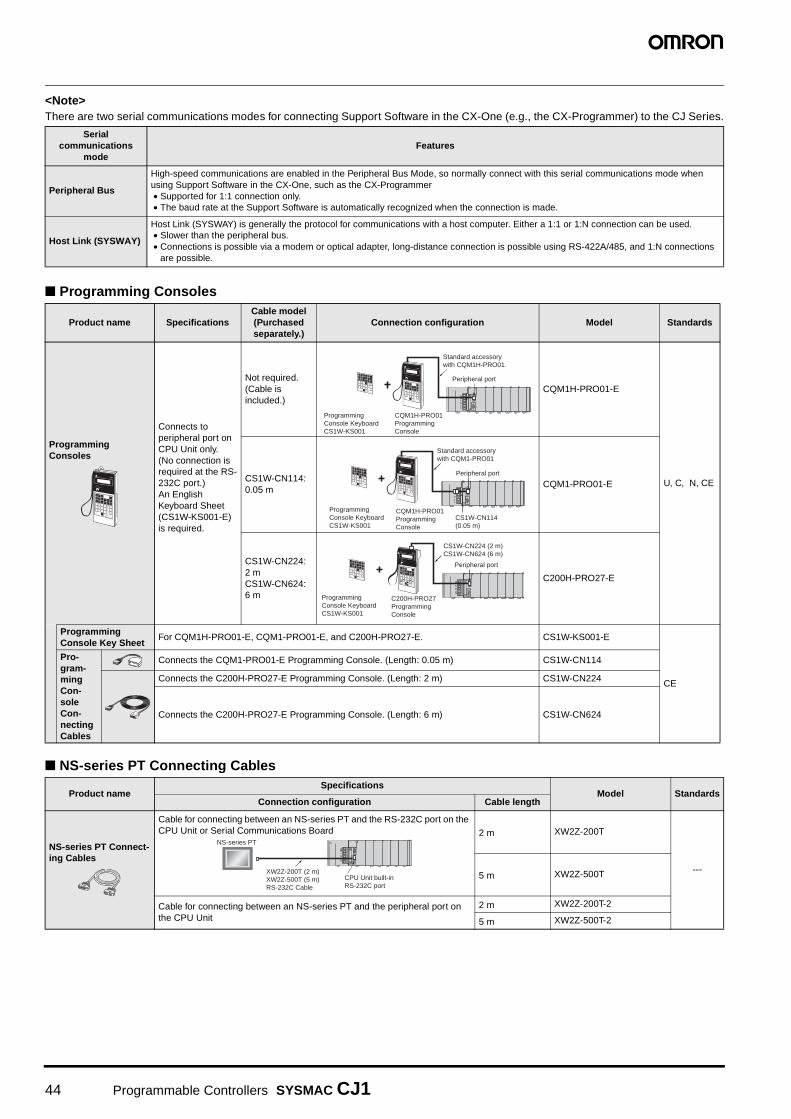
<Note>There are two serial communications modes for connecting Support Software in the CX-One (e.g., the CX-Programmer) to the CJ Series.
Programming Consoles
NS-series PT Connecting Cables
Serialcommunications
modeFeatures
Peripheral Bus
High-speed communications are enabled in the Peripheral Bus Mode, so normally connect with this serial communications mode when using Support Software in the CX-One, such as the CX-Programmer• Supported for 1:1 connection only.• The baud rate at the Support Software is automatically recognized when the connection is made.
Host Link (SYSWAY)
Host Link (SYSWAY) is generally the protocol for communications with a host computer. Either a 1:1 or 1:N connection can be used.• Slower than the peripheral bus.• Connections is possible via a modem or optical adapter, long-distance connection is possible using RS-422A/485, and 1:N connections
are possible.
Product name SpecificationsCable model(Purchased separately.)
Connection configuration Model Standards
Programming Consoles
Connects to peripheral port on CPU Unit only.(No connection is required at the RS-232C port.)An English Keyboard Sheet (CS1W-KS001-E) is required.
Not required. (Cable is included.)
CQM1H-PRO01-E
U, C, N, CECS1W-CN114: 0.05 m
CQM1-PRO01-E
CS1W-CN224: 2 mCS1W-CN624: 6 m
C200H-PRO27-E
Programming Console Key Sheet
For CQM1H-PRO01-E, CQM1-PRO01-E, and C200H-PRO27-E. CS1W-KS001-E
CE
Pro-gram-ming Con-sole Con-necting Cables
Connects the CQM1-PRO01-E Programming Console. (Length: 0.05 m) CS1W-CN114
Connects the C200H-PRO27-E Programming Console. (Length: 2 m) CS1W-CN224
Connects the C200H-PRO27-E Programming Console. (Length: 6 m) CS1W-CN624
Product nameSpecifications
Model StandardsConnection configuration Cable length
NS-series PT Connect-ing Cables
Cable for connecting between an NS-series PT and the RS-232C port on the CPU Unit or Serial Communications Board 2 m XW2Z-200T
---5 m XW2Z-500T
Cable for connecting between an NS-series PT and the peripheral port on the CPU Unit
2 m XW2Z-200T-2
5 m XW2Z-500T-2
Peripheral port
Standard accessory with CQM1H-PRO01.
CQM1H-PRO01ProgrammingConsole
Programming Console Keyboard CS1W-KS001
Programming Console Keyboard CS1W-KS001
Standard accessory with CQM1-PRO01
CS1W-CN114(0.05 m)
Peripheral port
CQM1H-PRO01ProgrammingConsole
CS1W-CN224 (2 m)CS1W-CN624 (6 m)
Programming Console Keyboard CS1W-KS001
Peripheral port
C200H-PRO27ProgrammingConsole
NS-series PT
CPU Unit built-in RS-232C port
XW2Z-200T (2 m)XW2Z-500T (5 m)RS-232C Cable
44 Programmable Controllers SYSMAC CJ1

Optional Products and Maintenance Products
Product name Specifications Model Standards
Memory Cards Flash memory, 128 MB HMC-EF183 N, L, CE
Memory Card Adapter (for computer PCMCIA slot) HMC-AP001 CE
Product name Specifications Model Standards
Battery Set Battery for CJ1G/H-CPU@@H-R/H/P CPU Unit maintenance
Note 1.The battery is included as a standard acces-sory with the CPU Unit.2. The battery service life is 5 years at 25°C.
(The service life depends on the ambient op-erating temperature and the power condi-tions.)
3. Use batteries within two years of manufac-ture.
CPM2A-BAT01 L, CE
Battery for CJ1M-CPU@@CPU Unit maintenance
CJ1W-BAT01 CE
End Cover Mounted to the right-hand side of CJ-series CPU Racks or Expansion Racks.
One End Cover is provided as a standard accessory with each CPU Unit and I/O Interface Unit.
CJ1W-TER01 UC1, N, L, CE
RS-422A Adapter Converts RS-233C to RS-422A/RS-485.(Application example: With a CJ1M CPU Unit, the Adapter is used for Serial PLC Link at the built-in RS-232C port of the CPU Unit.)
CJ1W-CIF11 UC1, N, L, CE
DIN Track Accessories
Product name Specifications Model Standards
DIN Track Length: 0.5 m; Height: 7.3 mm PFP-50N
---
Length: 1 m; Height: 7.3 mm PFP-100N
Length: 1 m; Height: 16 mm PFP-100N2
End Plate There are 2 stoppers provided with CPU Units and I/O Interface Units as standard accessories to secure the Units on the DIN Track.
PFP-M
Programmable Controllers SYSMAC CJ1 45

Input Units
Note: Connectors are not provided with these connector models. Either purchase one of the following 40-pin Connectors, or use an OMRON XW2@ Connector-Termi-nal Block Conversion Unit or a G7@ I/O Relay Terminal.
Basic I/O Units
Unit clas-sification
Product name
SpecificationsCurrent con-sumption (A)
Model Standards
I/O points Input voltage and
currentCommons
Additional functions
External connection
No. of words
allocated5 V 24 V
CJ1 Basic I/O Units
DC Input Units
8 inputs 12 to 24 VDC, 10 mAIndependent contacts
---
Removable terminal block
1 word 0.09 --- CJ1W-ID201
UC1, N, L, CE
16 inputs 24 VDC, 7 mA16 points, 1 common
Removable terminal block
1 word 0.08 --- CJ1W-ID211
32 inputs 24 VDC, 4.1 mA16 points, 1 common
Fujitsu connector 2 words 0.09 ---
CJ1W-ID231(See note.)
32 inputs 24 VDC, 4.1 mA16 points, 1 common
MIL connector 2 words 0.09 ---
CJ1W-ID232(See note.)
64 inputs 24 VDC, 4.1 mA16 points, 1 common
Fujitsu connector 4 words 0.09 ---
CJ1W-ID261(See note.)
64 inputs 24 VDC, 4.1 mA16 points,1 common
MIL connector 4 words 0.09 ---
CJ1W-ID262(See note.)
AC Input Units 16 inputs
100 to 120 VAC, 7 mA (100 V, 50 Hz)
16 points, 1 common
Removable Terminal Block
1 words 0.09 --- CJ1W-IA111
8 inputs200 to 24 VAC, 10 mA (200 V, 50 Hz)
8 points, 1 common
Removable Terminal Block
1 words 0.08 --- CJ1W-IA201
46 Programmable Controllers SYSMAC CJ1

Output Units
Note: Connectors are not provided with these connector models. Either purchase one of the following 40-pin Connectors, or use an OMRON XW2@ Connector-Termi-nal Block Conversion Unit or a G7@ I/O Relay Terminal.
Unit clas-sification
Product name
Specifications No. of words
allocated
Current con-sumption (A)
Model Standards
I/O pointsMaximum switching
capacity Commons
Additional functions
External connection
5 V 24 V
CJ1 Basic I/O Units
Relay Contact Output Units
8 outputs
250 VAC/24 VDC, 2 AIndepen-dent con-tacts
---
Remov-able termi-nal block
1 words 0.090.048 max.
CJ1W-OC201
UC1, N, L, CE
16 outputs
250 VAC/24 VDC, 2 A16 points, 1 common
Remov-able termi-nal block
1 words 0.110.096 max.
CJ1W-OC211
Transis-tor Output Units
8 outputs
12 to 24 VDC, 2 A, sinking,
4 points, 1 common
Remov-able termi-nal block
1 words 0.09 --- CJ1W-OD201
8 outputs
24 VDC, 2 A, sourcing4 points, 1 common
Short-circuit protection, disconnec-tion detection
Remov-able termi-nal block
1 words 0.11 --- CJ1W-OD202
8 outputs
12 to 24 VDC, 0.5 A,sinking
8 points, 1 common
---Remov-able termi-nal block
1 words 0.10 --- CJ1W-OD203
8 outputs
24 VDC, 0.5 A, sourcing
8 points, 1 common
Short-circuit protection
Remov-able termi-nal block
1 words 0.10 --- CJ1W-OD204
16 outputs
12 to 24 VDC, 0.5 A, sinking
16 points, 1 common
---Remov-able termi-nal block
1 words 0.10 --- CJ1W-OD211
16 outputs
24 VDC, 0.5 A, 16 points, 1 common
Short-circuit protection
Remov-able termi-nal block
1 words 0.10 --- CJ1W-OD212
32 outputs
12 to 24 VDC, 0.5 A, sinking
16 points, 1 common
---Fujitsu connector 2 words 0.14 ---
CJ1W-OD231(See note.)
32outputs
24 VDC, 0.5 A, sourcing
16 points, 1 common
Short-circuit protection
MIL connector 2 words 0.15 ---
CJ1W-OD232 (See note.)
32 outputs
12 to 24 VDC, 0.5 A, sinking
16 points, 1 common
---MIL connector 2 words 0.14 ---
CJ1W-OD233(See note.)
64 outputs
12 to 24 VDC, 0.3 A, sinking
16 points, 1 common
---Fujitsu connector 4 words 0.17 ---
CJ1W-OD261(See note.)
64 outputs
12 to 24 VDC, 0.3 A, sourcing
16 points, 1 common
---MIL connector 4 words 0.17 ---
CJ1W-OD262(See note.)
64 outputs
12 to 24 VDC, 0.3 A, sinking
16 points, 1 common
---MIL connector 4 words 0.17 ---
CJ1W-OD263(See note.)
Triac Out-put Unit
8 outputs
250 VAC, 0.6 A 8 points, 1 common
---Remov-able termi-nal block
1 words 0.22 --- CJ1W-OA201
Programmable Controllers SYSMAC CJ1 47

I/O Units
Note 1 .Connectors are not provided with these connector models. Either purchase one of the following 40-pin Connectors, or use an OMRON XW2@ Connector-Ter-minal Block Conversion Unit or a G7@ I/O Relay Terminal.
2. Connectors are not provided with these connector models. Either purchase one of the following 20-pin or 24-pin Connectors, or use an OMRON XW2@ Con-nector-Terminal Block Conversion Unit or a G7@ I/O Relay Terminal.
Applicable ConnectorsFujitsu Connectors for 32-input, 32-output, 64-input, 64-output, 32-input/32-output, and 16-input/16-output Units
Name Connection Remarks Applicable Units Model Standards
40-pin Connectors
Soldered FCN-361J040-AU ConnectorFCN-360C040-J2 Connector
Cover
Fujitsu Connectors: CJ1W-ID231(32 inputs): 1 per UnitCJ1W-ID261 (64 inputs) 2 per UnitCJ1W-OD231 (32 outputs):1 per UnitCJ1W-OD261 (64 outputs): 2 per UnitCJ1W-MD261 (32 inputs, 32 outputs): 2 per Unit
C500-CE404
---
Crimped FCN-363J040 HousingFCN-363J-AU ContactorFCN-360C040-J2 Connector
Cover
C500-CE405
Pressure welded
FCN-367J040-AU/F C500-CE403
24-pin Connectors
Soldered FCN-361J024-AU ConnectorFCN-360C024-J2 Connector
Cover
Fujitsu Connectors:CJ1W-MD231 (16 inputs, 16 outputs): 2 per Unit
C500-CE241
Crimped FCN-363J024 HousingFCN-363J-AU ContactorFCN-360C024-J2 Connector
Cover
C500-CE242
Pressure welded
FCN-367J024-AU/F C500-CE243
Unit clas-sification
Product name
SpecificationsCurrent con-sumption (A)
Model Standards
I/O points
Input voltage, Input current
CommonsAdditional functions
External connection
No. of words
allocated 5 V 24 V
Maximum switching capacity
CJ1 BasicI/O Units
DC Input/Transis-tor Output Units
16 inputs
24 VDC, 7 mA16 points,1 common
---Fujitsu connector 2 words 0.13 ---
CJ1W-MD231(See note 2.)
UC1, N, CE16
outputs250 VAC/24 VDC, 0.5 A, sinking
16 points, 1 common
---
16 inputs
24 VDC, 7 mA16 points,1 common
---MIL connector 2 words 0.13 ---
CJ1W-MD232(See note 2.)
UC1, N, L, CE16
outputs24 VDC, 0.5 A, sourcing
16 points, 1 common
Short-circuit protection
16 inputs
24 VDC, 7 mA16 points, 1 common
---MIL connector 2 words 0.13 ---
CJ1W-MD233(See note 2.)
UC1, N, CE
16 outputs
12 to 24 VDC, 0.5 A, sinking
16 points, 1 common
---
32 inputs
24 VDC, 4.1 mA16 points, 1 common
---Fujitsu connector 4 words 0.14 ---
CJ1W-MD261(See note 1.)32
outputs12 to 24 VDC, 0.3 A, sinking
16 points, 1 common
---
32 inputs
24 VDC, 4.1 mA16 points, 1 common
---MIL connector 4 words 0.14 ---
CJ1W-MD263(See note 1.)32
outputs12 to 24 VDC, 0.3 A,sinking
16 points, 1 common
---
TTL I/O Units 32
inputs5 VDC, 35 mA
16 points, 1 common
---
MIL connector 4 words 0.19 ---
CJ1W-MD563(See note 1.)
32 outputs
5 VDC, 35 mA16 points, 1 common
---
48 Programmable Controllers SYSMAC CJ1

MIL Connectors for 32-input, 32-output, 64-input, 64-output, 32-input/32-output, and 16-input/16-output Units
Interrupt Input Units
Note 1. Can be used only on CPU Racks, and not on Expansion Racks.2. The locations where the Units can be mounted depend on the CPU Rack and the CPU Unit model.
CJ1G, CJ1H: From the slot next to the CPU Unit until the fifth slot.CJ1M: From the slot next to the CPU Unit until the third slot.
High-speed Input Units
Note: There are no restrictions on the mounting position or number of Units.
B7A Interface Units
Name Connection Remarks Applicable Units Model Standards
40-pin Connectors
Pressure welded FRC5-AO40-3TOS MIL Connectors:CJ1W-ID232 (32 inputs): 1 per UnitCJ1W-OD232/233 (32 outputs):1 per UnitCJ1W-ID262 (64 inputs): 2 per UnitCJ1W-OD262/263 (64 outputs): 2 per UnitCJ1W-MD263/563 (32 inputs, 32 outputs): 2 per Unit
XG4M-4030-T
---
20-pin Connectors
Pressure welded FRC5-AO20-3TOS MIL Connectors:CJ1W-MD232/233 (16 inputs, 16 outputs): 2 per Unit
XG4M-2030-T
Unit clas-sification
Product name
SpecificationsNo. of words
allocated
Current con-sumption (A)
Model StandardsI/O
points
Input voltage current
Commons Input pulse width
conditions
Max. Units mountable
per Unit
External connec-
tion5 V 24 V
CJ1 BasicI/O Units
Interrupt Input Unit
16 inputs
24 VDC, 7 mA
16 points, 1 common
ON time: 0.05 ms max.OFF time: 0.5 ms max.
2
Remov-able termi-nal block
1 word 0.08 --- CJ1W-INT01UC1, N, L, CE
Unit clas-sification
Product name
Specifications
No. of words
allocated
Current con-sumption (A)
Model Standards I/O
points
Input voltage,
Input current
Commons Input pulse width
conditionsExternal
connection5 V 24 V
CJ1 BasicI/O Units
High- speed Input Unit
16 inputs
24 VDC, 7 mA
16 points, 1 common
ON time: 0.05 ms max.OFF time: 0.5 ms max.
Removable terminal block
1 word 0.08 --- CJ1W-IDP01UC1, N, L, CE
Unit clas-sification
Product name
Specifications No. of words allocated
Current con-sumption (A) Model Standards
I/O points External connection 5 V 24 V
CJ1 Basic I/O Units
B7A Inter-face Units
64 inputs
Removable terminal block 4 words
0.07 --- CJ1W-B7A14
UC1, CE64 outputs 0.07 --- CJ1W-B7A04
32 inputs/outputs 0.07 --- CJ1W-B7A22
Programmable Controllers SYSMAC CJ1 49

Process I/O Units Isolated-type Units with Universal Inputs
Note: L and −100°C or less for K and T are ±2°C±1 digit max., and 200°C or less for R and S is ±3°C±1 digit max. No accuracy is specified for 400°C or less for B.
Isolated-type Thermocouple Input Units
Note 1. The accuracy depends on the sensors used and the measurement temperatures. For details, refer to the user’s manual.2. This is for an external power supply, and not for internal current consumption.3. L and −100°C or less for K and T are ±2°C±1 digit max., and 200°C or less for R and S is ±3°C±1 digit max. No accuracy is specified for 400°C or less for B.
Special I/O Units and CPU Bus Units
Unit clas-sification
Product name
Input points
Signal range
selectionSignal range
Conversion speed
(resolution)
Accuracy (at ambient tem-perature of 25°C)
External connec-
tion
No. of unit
num-bers allo-cated
Current con-sumption (A)
Model Standards
5 V 24 V
CJ1 Special I/O Units
ProcessInput Units (Isolated-type Units with Uni-versal Inputs)
4 inputsSet sepa-rately for each input
Universal inputs:Pt100 (3-wire), JPt100 (3-wire), Pt1000 (3-wire), Pt100 (4-wire),K, J, T, E, L, U, N, R, S, B,WRe5-26, PL II,4 to 20 mA, 0 to 20 mA, 1 to 5 V, 0 to 1.25 V, 0 to 5 V, 0 to 10 V, ±100 mV select-able range−1.25 to 1.25 V, −5 to 5 V, −10 to 10 V, ±10 V selectable range, potentiom-eter
Resolution (conver-sion speed):1/256,000 (conver-sion cycle: 60 ms/4 inputs)1/64,000 (conver-sion cycle: 10 ms/4 inputs)1/16,000 (conver-sion cycle: 5 ms/4 inputs)
Standard accuracy: ±0.05% of F.S.
Remov-able ter-minal block
1
0.30 ---CJ1W-PH41U
---
4 inputsSet sepa-rately for each input
Universal inputs: Pt100, JPt100, Pt1000, K, J, T, L, R, S, B, 4 to 20 mA, 0 to 20 mA, 1 to 5 V, 0 to 5 V, 0 to 10 V
Conversion speed: 250 ms/4 inputs
Accuracy:Platinum resistance thermometer input: (±0.3% of PV or ±0.8°C, whichever is larger) ±1 digit max.Thermocouple input: (±0.3% of PV or ±1.5°C, whichever is larger) ±1 digit max. (See note.)Voltage or current input: ±0.3% of F.S. ±1 digit max.
0.32 ---CJ1W-AD04U
---
Unit clas-sification
Product name
Input points
Signal range
selectionSignal range
Conversion speed
(resolution)
Accuracy(at ambient
temperature of 25°C)
External connection
No. of unit numbers allocated
Current con-sumption (A)
Model Standards
5 V 24 V
CJ1 Special I/O Units
Process Input Units (Isolated-type Ther-mocouple Input Units)
2 inputs
Set sep-arately for each input
Thermocouple:B, E, J, K, L, N, R, S, T, U, WRe5-26, PLIIDC voltage:±100 mV
Conversion speed: 10 ms/2 inputs, Resolution: 1/64,000
Standard accuracy: ±0.05% of F.S.(See note 1.)
Removable terminal block
1
0.18
0.06 (See note 2.)
CJ1W-PTS15
UC1, CE4
inputsThermocouple:R, S, K, J, T, L, B
Conversion speed: 250 ms/4 inputs
Accuracy: (±0.3% of PV or ±1°C, whichever is larger) ±1 digit max. (See note 3.)
0.25 ---CJ1W-PTS51
Available soon
Available soon
50 Programmable Controllers SYSMAC CJ1

Isolated-type Resistance Thermometer Input Units
Note: This is for an external power supply, and not for internal current consumption.
Isolated-type DC Input Units
Note: This is for an external power supply, and not for internal current consumption.
Analog I/O Units Analog Input Units
Note 1. The resolution and conversion speed cannot be set independently. If the resolution is set to 1/4,000, then the conversion speed will be 1 ms/point.2. At 23 ±2°C
Unit clas-sification
Product name
Input points
Signal range
selectionSignal range
Conversion speed
(resolution)
Accuracy (at ambient
temperature of 25°C)
External connec-
tion
No. of unit
num-bers allo-cated
Current con-sumption (A)
Model Standards
5 V 24 V
CJ1 Special I/O Units
Process Analog Input Units (Isolated-type Resis-tance Thermom-eter Input Units)
2 inputs
Set sep-arately for each input
Resistance ther-mometer: Pt100, JPt100, Pt50, Ni508.4
Conver-sion speed: 10 ms/2 inputs, Resolution: 1/64,000
Accuracy: ±0.05% of F.S. or ±0.1°C, whichever is larger.
Remov-able termi-nal block
1
0.180.07 (See note.)
CJ1W-PTS16
UC1, CE4 inputs
Com-mon inputs
Resistance ther-mometer: Pt100, JPt100
Conver-sion speed: 250 ms/4 inputs
Accuracy: ±0.3°C of PV or ±0.8°C, which-ever is larger, ±1 digit max. 0.25 --- CJ1W-PTS52
Unit clas-sification
Product name
Input points
Signal range selectionConversion
speed (resolution)
Accuracy (at ambient temperature
of 25°C)
External connec-
tion
No. of unit
numbers allocated
Current con-sumption (A)
Model Standards
5 V 24 V
CJ1 Special I/O Units
Isolated-type DC Input Units
2 inputs
DC voltage:0 to 1.25 V, −1.25 to 1.25 V, 0 to 5 V, 1 to 5 V, −5 to 5 V, 0 to 10 V, −10 to 10 V, ±10 V selectable range
DC current:0 to 20 mA, 4 to 20 mA
Conversion speed: 10 ms/2 inputs
Resolution: 1/64,000
Standard accuracy: ±0.05% of F.S.
Remov-able terminal block
1 0.180.09 (See note.)
CJ1W-PDC15 UC1, CE
Unit clas-sification
Product name
Input points
Signal range selec-tion
Signal range
ResolutionConversion
speed
Accuracy (at ambient
temperature of 25°C)
External connec-
tion
No. of unit
numbers allocated
Current consump-
tion (A) Model Standards
5 V 24 V
CJ1 Special I/O Units
Analog Input Units
8 inputs
Set sepa-rately for each input
1 to 5 V, 0 to 5 V, 0 to 10 V, −10 to 10 V, 4 to 20 mA
1/8000, (Settable to 1/4000) (See note 1.)
250 µs/point max. (Settable to 1 ms/point)(See note 1.)
Voltage:±0.2% of F.S.
Current:±0.4% of F.S.(See note 2.)
Remov-able termi-nal block
1
0.42 ---CJ1W-AD081-V1
UC1, N, L, CE
4 inputs 0.42 ---
CJ1W-AD041-V1
Programmable Controllers SYSMAC CJ1 51
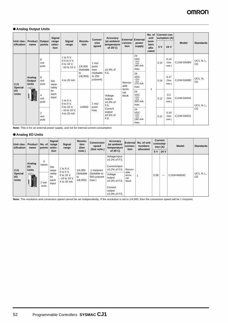
Analog Output Units
Note: This is for an external power supply, and not for internal current consumption
Analog I/O Units
Note: The resolution and conversion speed cannot be set independently. If the resolution is set to 1/4,000, then the conversion speed will be 1 ms/point.
Unit clas-sification
Product name
Output points
Signal range selec-tion
Signal range
Resolu-tion
Conver-sion
speed
Accuracy (at ambient temperature
of 25°C)
External connec-
tion
External power supply
No. of unit
num-bers allo-cated
Current con-sumption (A)
Model Standards
5 V 24 V
CJ1 Special I/O Units
Analog Output Units
8 out-puts
Set sepa-rately for each input
1 to 5 V, 0 5 to 5 V, 0 to 10 V, −10 to 10 V 1/4,000
(Settable to 1/8,000)
1 ms/point max. (Settable to 250 µs/point)
±0.3% of F.S.
Remov-able termi-nal block
24 VDC
, 140 mA max.
1
0.140.14 (See note.)
CJ1W-DA08VUC1, N, L, CE
8 out-puts
4 to 20 mA
24 VDC
, 170 mA max.
0.140.17 (See note.)
CJ1W-DA08CUC1, N, CE
4 out-puts 1 to 5 V,
0 to 5 V, 0 to 10 V, −10 to 10 V, 4 to 20 mA
1/40001 ms/point max.
Voltage output: ±0.3% of F.S.Current output: ±0.5% of F.S.
24 VDC
, 200 mA max.
0.120.2 (See note.)
CJ1W-DA041
UC1, N, L, CE
2 out-puts
24 VDC
, 140 mA max.
0.120.14 (See note.)
CJ1W-DA021
Unit clas-sification
Product name
No. of points
Signal range selec-tion
Signal range
Resolu-tion (See
note.)
Conversion speed
(See note.)
Accuracy (at ambient temperature
of 25°C)
External connec-
tion
No. of unit numbers allocated
Current consump-
tion (A) Model Standards
5 V 24 V
CJ1 Special I/O Units
Analog I/O Units
4 inputs
Set sepa-rately for each input
1 to 5 V, 0 to 5 V, 0 to 10 V, −10 to 10 V, 4 to 20 mA
1/4,000 (Settable to 1/8,000)
1 ms/point (Settable to 500 µs/point max.)
Voltage input: ±0.2% of F.S.
Current input: ±0.2% of F.S. Remov-
able termi-nal block
1 0.58 --- CJ1W-MAD42UC1, N, L, CE
2 out-puts
Voltage output: ±0.3% of F.S.
Current output: ±0.3% of F.S.
+10%−15%
+10%−15%
+10%−15%
+10%−15%
52 Programmable Controllers SYSMAC CJ1

Temperature Control Units
High-speed Counter Unit
Unit clas-sification
Product name
Specifications No. of unit numbers allocated
Current con-sumption (A)
Model Standards
No. of loopsTemperature sensor inputs
Control outputs 5 V 24 V
CJ1 Special I/O Units
Temper-ature Control Units
4 loops
Thermocouple input (R, S, K, J, T, B, L)
Open collector NPN outputs (pulses)
2
0.25 --- CJ1W-TC001
UC1, N, L, CE
4 loopsOpen collector PNP outputs (pulses) 0.25 --- CJ1W-TC002
2 loops, heater burnout detection function
Open collector NPN outputs (pulses) 0.25 --- CJ1W-TC003
2 loops, heater burnout detection function
Open collector PNP outputs (pulses) 0.25 --- CJ1W-TC004
4 loops
Platinum resistance thermometer input (JPt100, Pt100)
Open collector NPN outputs (pulses) 0.25 --- CJ1W-TC101
4 loopsOpen collector PNP outputs (pulses) 0.25 --- CJ1W-TC102
2 loops, heater burnout detection function
Open collector NPN outputs (pulses) 0.25 --- CJ1W-TC103
2 loops, heater burnout detection function
Open collector PNP outputs (pulses) 0.25 --- CJ1W-TC104
Unit clas-sification
Product name
Specifications No. of unit
numbers allocated
Current con-sumption (A)
Model StandardsCountable channels
Encoder A and B inputs, pulse input Z signals
Max. counting
rate5 V 24 V
CJ1 Special I/O Units
High-speed Counter Unit
2
Open collectorInput voltage: 5 VDC, 12 V, or 24 V (5 V and 12 V are each for one axis only.)
50 kcps
4 0.28 --- CJ1W-CT021UC1, N, L, CE
RS-422 line driver 500 kcps
Programmable Controllers SYSMAC CJ1 53

Position Control Units
Note 1. The ambient operating temperature for 4-Axis Position Control Units is 0 to 50°C; the allowable voltage fluctuation on the external 24-VDC power supply is 22.8 to 25.2 VDC (24 V ±5%).
2. Site licenses are available for the CX-One (3, 10, 30, or 50 licenses). For details, refer to Support Software on page 42.3. When purchasing the DVD format, verify the computer model and DVD drive specifications before purchasing.
Unit classifi-cation
Product name
Specifications No. of unit numbers allocated
Current consump-
tion (A) Model Standards
No. of axes
Control output interface 5 V 24 V
CJ1 Special I/O Units
Position Control Units
1 axis Pulse train, open collector output1
0.25 --- CJ1W-NC113
UC1, CE
2 axes Pulse train, open collector output 0.25 --- CJ1W-NC213
4 axesPulse train, open collector output (See note 1.)
2 0.36 --- CJ1W-NC413
1 axis Pulse train, line driver output1
0.25 --- CJ1W-NC133
2 axes Pulse train, line driver output 0.25 --- CJ1W-NC233
4 axesPulse train, line driver output (See note 1.)
2 0.36 --- CJ1W-NC433
Space Unit Use a CJ1W-SP001 Space Unit if the operating temperature is 0 to 55°C. CJ1W-SP001 UC1, CE
CX-One FA Inte-grated Tool Package Ver. 2.@
The CX-One is a package that integrates the Support Software for OMRON PLCs and components. CX-One runs on the following OS. Windows 98SE, Me, NT4.0 (Service Pack 6a), 2000 (Service Pack 3a or higher), XP, or VistaCX-One Ver. 2.@ includes CX-Position Ver. [email protected] details, refer to the CX-One catalog (Cat. No. R134).
1 licenseMedia: CD(See note 2.)
CXONE-AL01C-EV2
---1 licenseMedia: DVD (See notes 2 and 3.)
CXONE-AL01D-EV2
Servo Relay Units
For 1-Axis Position Control Unit (without communications support) (CJ1W-CN113/133) XW2B-20J6-1B
---For 2- or 4-Axis Position Control Unit (without communications support) (CJ1W-NC213/233/413/433)
XW2B-40J6-2B
For 2- or 4-Axis Position Control Unit (with communications support) (CJ1W-NC213/233/413/433)
XW2B-40J6-4A
Position Control Unit Cables
For CJ1W-NC113: Pulse train, open collector output, 1 axis Connecting Servo
Driver: OMNUC G/W Series, SMARTSTEP2
Cable length: 0.4 m XW2Z-050J-A14
---
Cable length: 1 m XW2Z-100J-A14
For CJ1W-NC213/413: Pulse train, open collector output, 2 axes/4 axes
Cable length: 0.5 m XW2Z-050J-A15
Cable length: 1 m XW2Z-100J-A15
For CJ1W-NC113: Pulse train, open collector output, 1 axis Connecting Servo
Driver: SMARTSTEP Junior/A Series
Cable length: 0.5 m XW2Z-050J-A16
Cable length: 1 m XW2Z-100J-A16
For CJ1W-NC213/413: Pulse train, open collector output, 2 axes/4 axes
Cable length: 0.5 m XW2Z-050J-A17
Cable length: 1 m XW2Z-100J-A17
For CJ1W-NC133: Pulse train, line-driver output, 1 axis Connecting Servo
Driver: OMNUC G/W Series, SMARTSTEP2
Cable length: 0.5 m XW2Z-050J-A18
Cable length: 1 m XW2Z-100J-A18
For CJ1W-NC233/433: Pulse train, line driver output, 2 axes/4 axes
Cable length: 0.5 m XW2Z-050J-A19
Cable length: 1 m XW2Z-100J-A19
For CJ1W-NC133: Pulse train, line-driver output, 1 axis Connecting Servo
Driver: SMARTSTEP Junior/A Series
Cable length: 0.5 m XW2Z-050J-A20
Cable length: 1 m XW2Z-100J-A20
For CJ1W-NC233/433: Pulse train, line driver output, 2 axes/4 axe
Cable length: 0.5 m XW2Z-050J-A21
Cable length: 1 m XW2Z-100J-A21
54 Programmable Controllers SYSMAC CJ1

MECHATROLINK-II-compatible Position Control Units
Note 1. Site licenses are available for the CX-One (3, 10, 30, or 50 licenses). For details, refer to Support Software on page 42.2. When purchasing the DVD format, verify the computer model and DVD drive specifications before purchasing.
Unit classi-fication
Product name SpecificationsNo. of unit numbers allocated
Current con-sumption (A) Model Standards5 V 24 V
CJ1 CPU Bus Units
MECHA-TROLINK-II-compatible Motion Con-trol Units
Control commands executed by MECHATROLINK-II synchronous communications.16 axes max.Direct operation by ladder programming.Control mode: Position control, speed control, or torque control
1 0.36 --- CJ1W-NCF71 UC1, CE
MECHA-TROLINK-II Interface Unit
R88D-WT@ OMNUC W-series AC Servo Driver (Yaskawa Electric Corporation)Use the model numbers provided in this catalog when ordering from OMRON.
FNY-NS115 ---
MECHA-TROLINK-II Cables
Connects MECHATROLINK-II-compatible devices (Yaskawa Electric Corporation)Use the model numbers provided in this catalog when ordering from OMRON.
Cable length: 0.5 m FNY-W6003-A5
---
Cable length: 1 m FNY-W6003-01
Cable length: 3 m FNY-W6003-03
Cable length: 5 m FNY-W6003-05
Cable length: 10 m FNY-W6003-10
Cable length: 20 m FNY-W6003-20
Cable length: 30 m FNY-W6003-30
MECHA-TROLINK-II Terminat-ing Resis-tors
Terminating Resistor for MECHATROLINK-II (Yaskawa Electric Corporation)Use the model numbers provided in this catalog when ordering from OMRON.
FNY-W6022 ---
CX-One FA Integrated Tool Package Ver. 2.@
The CX-One is a package that integrates the Support Software for OMRON PLCs and components. CX-One runs on the following OS. Windows 98SE, Me, NT4.0 (Service Pack 6a), 2000 (Service Pack 3a or higher), XP, or VistaCX-One Ver. 2.@ includes CX-Motion-NCF Ver. [email protected] details, refer to the CX-One catalog (Cat. No. R134).
1 licenseMedia: CD (See note 1.)
CXONE-AL01C-EV2
---1 licenseMedia: DVD (See notes 1 and 2.)
CXONE-AL01D-EV2
Programmable Controllers SYSMAC CJ1 55

MECHATROLINK-II-compatible Motion Control Units
Note 1. Site licenses are available for the CX-One (3, 10, 30, or 50 licenses). For details, refer to Support Software on page 42.2. When purchasing the DVD format, verify the computer model and DVD drive specifications before purchasing.3. The CJ1W-MCH71 requires the space of three Units (but just one unit number). A maximum of 10 Units can be mounted on a single CJ-series Rack, up to
three CJ1W-MCH71 Motion Control Units plus one other Unit can be mounted per Rack.
Unit clas-sification
Product name SpecificationsNo. of unit numbers allocated
Current con-sumption (A) Model Standards5 V 24 V
CJ1 CPU Bus Units
MECHA-TROLINK-II-compatible Motion Con-trol Units Position, speed, and torque commands by MECHATROLINK-II
32 axes max. (Physical axes: 30, Virtual axes: 2) Motion control language
1 0.6 0.3 CJ1W-MCH71 UC1, CE
MECHA-TROLINK Unit
Refer to the section on MECHATROLINK-II-compatible Position Control Units above on page 55.
MECHA-TROLINK-II Cables
Refer to the section on MECHATROLINK-II-compatible Position Control Units above on page 55.
MECHA-TROLINK-II Terminat-ing Resis-tors
Refer to the section on MECHATROLINK-II-compatible Position Control Units above on page 55.
MECHA-TROLINK- II Repeater
For more than 15 slaves/30 m FNY-REP2000
---
MECHA-TROLINK-II 24-VDC I/O Module
Inputs: 64Outputs: 64
FNY-IO2310
MECHA-TROLINK-II Counter Module
Reversible counter, 2 words FNY-PL2900
MECHA-TROLINK-II Pulse Out-put Module
Pulse train positioning, 2 words FNY-PL2910
CX-One FA IntegratedTool Package Ver. 2.@
The CX-One is a package that integrates the Support Software for OMRON PLCs and components. CX-One runs on the following OS.Windows 98SE, Me, NT4.0 (Service Pack 6a), 2000 (Service Pack 3a or higher), XP, or VistaCX-One Ver. 2.@ includes CX-Motion-MCH Ver. [email protected] details, refer to the CX-One catalog (Cat. No. R134).
1 licenseMedia: CD(See note 1.)
CXONE-AL01C-EV2
1 licenseMedia: DVD(See notes 1 and 2.)
CXONE-AL01D-EV2
56 Programmable Controllers SYSMAC CJ1

Serial Communications Units
Note 1. The Serial Gateway function is enabled only for Serial Communications Units of unit version 1.2 and later.2. The no-protocol function is enabled only for Serial Communications Units of unit version 1.2 and later (and a CPU Unit of unit version 3.0 or later is also re-
quired).3. The Modbus-STU Slave function is enabled only for Serial Communications Units of unit version 1.3 and later.4. When an NT-AL001 RS-232C/RS-422A Conversion Unit is used, this value increases by 0.15 A/Unit. When a CJ1W-CIF11 RS-422A Conversion Unit is used,
it increases by 0.04 A/Unit.5. Site licenses are available for the CX-One (3, 10, 30, or 50 licenses). For details, refer to Support Software on page 42.6. When purchasing the DVD format, verify the computer model and DVD drive specifications before purchasing.
Ethernet Unit
Unit clas-sification
Product nameSpecifications No. of unit
numbers allocated
Current con-sumption (A)
Model StandardsCommunications
InterfaceCommunications functions 5 V 24 V
CJ1 CPU Bus Units
Serial Com-munications Units
1 RS-232C port and 1 RS-422A/485 port
The following functions can be selected for each port:Protocol macroHost LinkNT Links (1:N mode)Serial Gateway (See note 1.)No-protocol (See note 2.)Modbus-RTU Slave (See note 3.)
1
0.38 (See note 4.)
--- CJ1W-SCU41-V1
UC1, N, L, CE2 RS-232C ports
0.28 (See note 4.)
--- CJ1W-SCU21-V1
2 RS-422A/485 ports 0.38 --- CJ1W-SCU31-V1
CX-One FA Integrated Tool Package Ver. 2.@
The CX-One is a package that integrates the Support Software for OMRON PLCs and components. CX-One runs on the following OS. Windows 98SE, Me, NT4.0 (Service Pack 6a), 2000 (Service Pack 3a or higher), XP, or VistaCX-One Ver. 2.@ includes CX-Protocol Ver. [email protected] details, refer to the CX-One catalog (Cat. No. R134).
1 licenseMedia: CD(See note 5.)
CXONE-AL01C-EV2
---1 licenseMedia: DVD(See notes 5 and 6.)
CXONE-AL01D-EV2
CX-Protocol can still be ordered individually in the following model number.
CX-Proto-col Ver.1.@
Software to create protocol macrosNote: Can be used with CJ1G/CJ1H version 1.2 or later, and with
CJ1M version 1.3 and later.OS: Windows 98SE, Me, NT4.0 (Service Pack 6a), 2000 (Service Pack 3a or higher), XP, or Vista
1 licenseMedia: CD
WS02-PSTC1-E ---
Unit clas-sification
Product name
Specifications
No. of unit numbers allocated
Current con-sumption (A)
Model StandardsCommunica-tions cable
Communications functions
Max.Units mountable per CPU
Unit
5 V 24 V
CJ1 CPU Bus Unit
Ethernet Unit
100Base-TX
FINS communications service (TCP/IP, UDP/IP), FTP server functions, socket services, mail transmission service, mail reception (remote command receive), automatic adjustment of PLC’s built-in clock, server/host name specifications
4 1 0.37 --- CJ1W-ETN21UC1, N, L, CE
Programmable Controllers SYSMAC CJ1 57
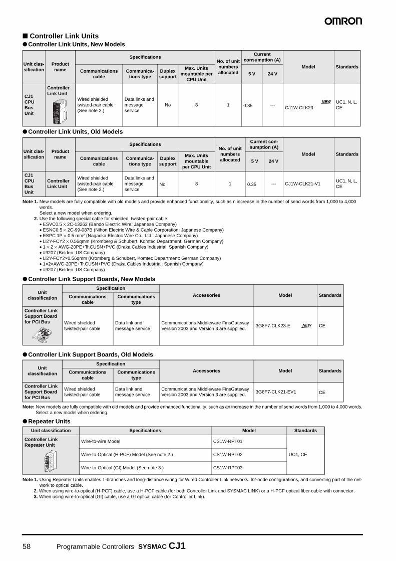
Controller Link Units Controller Link Units, New Models
Controller Link Units, Old Models
Note 1. New models are fully compatible with old models and provide enhanced functionality, such as n increase in the number of send words from 1,000 to 4,000 words.Select a new model when ordering.
2. Use the following special cable for shielded, twisted-pair cable.• ESVC0.5 × 2C-13262 (Bando Electric Wire: Japanese Company)• ESNC0.5 × 2C-99-087B (Nihon Electric Wire & Cable Corporation: Japanese Company)• ESPC 1P × 0.5 mm2 (Nagaoka Electric Wire Co., Ltd.: Japanese Company)• Li2Y-FCY2 × 0.56qmm (Kromberg & Schubert, Komtec Department: German Company)• 1 × 2 × AWG-20PE+Tr.CUSN+PVC (Draka Cables Industrial: Spanish Company)• #9207 (Belden: US Company)• Li2Y-FCY2×0.56qmm (Kromberg & Schubert, Komtec Department: German Company)• 1×2×AWG-20PE+Tr.CUSN+PVC (Draka Cables Industrial: Spanish Company)• #9207 (Belden: US Company)
Controller Link Support Boards, New Models
Controller Link Support Boards, Old Models
Note: New models are fully compatible with old models and provide enhanced functionality, such as an increase in the number of send words from 1,000 to 4,000 words.Select a new model when ordering.
Repeater Units
Note 1. Using Repeater Units enables T-branches and long-distance wiring for Wired Controller Link networks. 62-node configurations, and converting part of the net-work to optical cable.
2. When using wire-to-optical (H-PCF) cable, use a H-PCF cable (for both Controller Link and SYSMAC LINK) or a H-PCF optical fiber cable with connector.3. When using wire-to-optical (GI) cable, use a GI optical cable (for Controller Link).
Unit clas-sification
Product name
SpecificationsNo. of unit numbers allocated
Current consumption (A)
Model StandardsCommunications
cableCommunica-
tions typeDuplex support
Max. Units mountable per
CPU Unit5 V 24 V
CJ1 CPU Bus Unit
Controller Link Unit
Wired shielded twisted-pair cable (See note 2.)
Data links and message service
No 8 1 0.35 ---CJ1W-CLK23
UC1, N, L, CE
Unit clas-sification
Product name
SpecificationsNo. of unit numbers allocated
Current con-sumption (A)
Model StandardsCommunications
cableCommunica-
tions typeDuplex support
Max. Units mountable
per CPU Unit5 V 24 V
CJ1 CPU Bus Unit
Controller Link Unit
Wired shielded twisted-pair cable (See note 2.)
Data links and message service
No 8 1 0.35 --- CJ1W-CLK21-V1UC1, N, L, CE
Unit classification
Specification
Accessories Model StandardsCommunications cable
Communications type
Controller Link Support Board for PCI Bus Wired shielded
twisted-pair cableData link and message service
Communications Middleware FinsGateway Version 2003 and Version 3 are supplied.
3G8F7-CLK23-E CE
Unit classification
Specification
Accessories Model StandardsCommunicationscable
Communications type
Controller Link Support Board for PCI Bus
Wired shielded twisted-pair cable
Data link and message service
Communications Middleware FinsGateway Version 2003 and Version 3 are supplied.
3G8F7-CLK21-EV1 CE
Unit classification Specifications Model Standards
Controller Link Repeater Unit
Wire-to-wire Model CS1W-RPT01
UC1, CEWire-to-Optical (H-PCF) Model (See note 2.) CS1W-RPT02
Wire-to-Optical (GI) Model (See note 3.) CS1W-RPT03
CS1W-RPT01PWRT/R1T/R2
SL1
TER SW
TER SW
ON
SL2
DC24VINPUT
1 BAUD2 RATE
SW1
58 Programmable Controllers SYSMAC CJ1

Relay Terminal Block
Note: Controller Link Units can be replaced without stopping the communications of the entire network if a Relay Terminal Block is installed in advance on the Unit ina Wired Controller Link network. Relay Blocks cannot be used on Controller Link Support Boards.
H-PCF Cables and Optical Connectors
Unit classification Specifications Model Standards
Relay Terminal Block for Wired Controller Link Unit
Use for Wired Controller Link Units (set of 5). CJ1W-TB101 ---
Name Application/construction Specifications Model Standards
Optical Fiber Cables
ControllerLink, SYSMACLINK, SYSBUS
(1) Optical fiber single-core cord(2) Tension member (plastic-
sheathed wire)(3) Filler (plastic)(4) Filler surrounding signal wires
(plastic, yarn, or fiber)(5) Holding tape (plastic)(6) Heat-resistant PV sheath
Two-core optical cable with tension member
Black 10 m S3200-HCCB101
---
Black 50 m S3200-HCCB501
Black 100 m S3200-HCCB102
Black 500 m S3200-HCCB502
Black 1,000 m S3200-HCCB103
Orange 10 m S3200-HCCO101
Orange 50 m S3200-HCCO501
Orange 100m S3200-HCCO102
Orange 500 m S3200-HCCO502
Orange 1,000 m S3200-HCCO103
Optical Connec-tors (Crimp-cut)
CS1W-RPT02
Half lock S3200-COCF2571
Full lock S3200-COCF2071
(1)(2)
(4)(3)
(5)(6)
Programmable Controllers SYSMAC CJ1 59

H-PCF Optical Fiber Cables with Connectors (Black Composite Cables with Two-Optical Lines and Two Power Supply Lines)
• Cable LengthThe following cable lengths are available: 2 m, 5 m, 15 m, 20 m.
For lengths of 21 m or more, contact your OMRON sales repre-
sentative.
• Model Numbers
• Optical Connector Assembly Tool
Note: There is a risk of quality problems when using cables assembled by typ-ical users, so we recommend purchasing cables with preattached con-nectors or having a qualified technician assemble the cables.Optical connectors for H-PCF Optical Cables with Connectors are adhe-sive polished.
GI Optical CablesA qualified technician must select, assemble, and install GI
Optical Fiber Cable, so always let an optical cable specialist
handle the GI cable.
Usable Optical Cables and Optical Connectors
• Optical fiber types: Graded, indexed, multi-mode, all quartz
glass, fiber (GI-type AGF cable)
• Optical fiber construction (core diameter/clad diameter):
62.5/125 µm or 50/125 µm
• Optical fiber optical characteristics of optical fiber: Refer to the
tables.
• Optical connector: ST connector (IEC-874-10)
• 50/125 µm AGF Cable
Lf is fiber length in km, Ta is ambient temperature, and λ: is the peak wave-length of the test light source.
• 62.5/125 µm AGF Cable
Lf is fiber length in km, Ta is ambient temperature, and λ is the peak wavelength of the test light source.
Application Appearance ModelStan-dards
Controller Link, SYSMAC Link
S3200-CN@@@-20-20
---S3200-CN@@@-20-25
S3200-CN@@@-25-25
Name Applicable Unit Model ManufacturerStan-dards
Optical Fiber Assem-bly Tool (See note.)
This tool is used on site for mounting crimp-cut connectors and hard plastic-clad silica opti-cal fiber for optical transmission systems of SYSMAC C-series SYSBUS, SYSMAC LINK, and Controller Link.
CAK-0057
Sumitomo Electric Industries, Ltd.
---
@@@201
501
102
152
202
Length2 m
5 m
10 m
15 m
20 m
20
25
Number Connector appearance
Full lock
Half lock
Lengths of 2 m, 5 m, 10 m, 15 m, and 20 m
Example: S3200-CN@@@@@@-20-25(1) (2) (3)
Length of 21 m or more
Example: S3200-CN-20-20(1) (3) Specify the
cable length in meters.
(2)Cable Length
Cable length
(1)H-PCF optical fiber cable
(1) Connectors at Both Ends
Item Minimum Standard Maximum Remarks
Numerical Aperture (N.A)
--- 0.21 --- ---
Transmis-sion loss (dB)
--- ---
3.0 Lf0.5 km ≤
Lf
λ = 0.8 µmTa = 25°C
3.0 Lf + 0.2
0.2 km ≤
Lf ≤ 0.5 km
3.0 Lf + 0.4
Lf ≤ 0.2 km
Connec-tion loss (dB)
--- --- 1.0λ = 0.8 µm, one location
Transmis-sion band-width (MHz-km)
500 --- --- λ = 0.85µm (LD)
Item Minimum Standard Maximum Remarks
Numerical Aperture (N.A)
--- 0.28 --- ---
Transmis-sion loss (dB)
--- ---
3.5 Lf0.5 km ≤
Lf
λ = 0.8 µmTa = 25°C
3.5 Lf + 0.2
0.2 km ≤
Lf ≤ 0.5 km
3.5 Lf + 0.4
Lf ≤ 0.2 km
Connec-tion loss (dB)
--- --- 1.0λ = 0.8 µm, one location
Transmis-sion band-width (MHz-km)
200 --- --- λ = 0.85 µm (LD)
60 Programmable Controllers SYSMAC CJ1
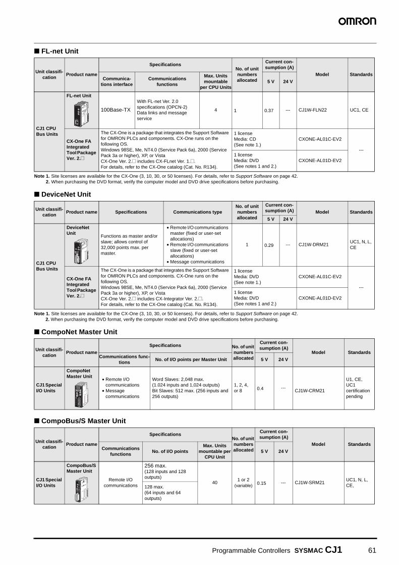
FL-net Unit
Note 1. Site licenses are available for the CX-One (3, 10, 30, or 50 licenses). For details, refer to Support Software on page 42.2. When purchasing the DVD format, verify the computer model and DVD drive specifications before purchasing.
DeviceNet Unit
Note 1. Site licenses are available for the CX-One (3, 10, 30, or 50 licenses). For details, refer to Support Software on page 42.2. When purchasing the DVD format, verify the computer model and DVD drive specifications before purchasing.
CompoNet Master Unit
CompoBus/S Master Unit
Unit classifi-cation
Product name
SpecificationsNo. of unit numbers allocated
Current con-sumption (A)
Model StandardsCommunica-
tions interfaceCommunications
functions
Max. Units mountable
per CPU Units5 V 24 V
CJ1 CPU Bus Units
FL-net Unit
100Base-TX
With FL-net Ver. 2.0 specifications (OPCN-2)Data links and message service
4 1 0.37 --- CJ1W-FLN22 UC1, CE
CX-One FA Integrated Tool Package Ver. 2.@
The CX-One is a package that integrates the Support Software for OMRON PLCs and components. CX-One runs on the following OS. Windows 98SE, Me, NT4.0 (Service Pack 6a), 2000 (Service Pack 3a or higher), XP, or VistaCX-One Ver. 2.@ includes CX-FLnet Ver. [email protected] details, refer to the CX-One catalog (Cat. No. R134).
1 licenseMedia: CD(See note 1.)
CXONE-AL01C-EV2
---1 licenseMedia: DVD(See notes 1 and 2.)
CXONE-AL01D-EV2
Unit classifi-cation
Product name Specifications Communications typeNo. of unit numbers allocated
Current con-sumption (A) Model Standards
5 V 24 V
CJ1 CPU Bus Units
DeviceNet Unit
Functions as master and/or slave; allows control of 32,000 points max. per master.
• Remote I/O communications master (fixed or user-set allocations)
• Remote I/O communications slave (fixed or user-set allocations)
• Message communications
1 0.29 --- CJ1W-DRM21UC1, N, L, CE
CX-One FA Integrated Tool Package Ver. 2.@
The CX-One is a package that integrates the Support Software for OMRON PLCs and components. CX-One runs on the following OS. Windows 98SE, Me, NT4.0 (Service Pack 6a), 2000 (Service Pack 3a or higher), XP, or VistaCX-One Ver. 2.@ includes CX-Integrator Ver. [email protected] details, refer to the CX-One catalog (Cat. No. R134).
1 licenseMedia: DVD(See note 1.)
CXONE-AL01C-EV2
---1 licenseMedia: DVD(See notes 1 and 2.)
CXONE-AL01D-EV2
Unit classifi-cation
Product name
Specifications No. of unit numbers allocated
Current con-sumption (A)
Model StandardsCommunications func-
tionsNo. of I/O points per Master Unit 5 V 24 V
CJ1 Special I/O Units
CompoNet Master Unit
• Remote I/O communications
• Message communications
Word Slaves: 2,048 max. (1.024 inputs and 1,024 outputs)Bit Slaves: 512 max. (256 inputs and 256 outputs)
1, 2, 4, or 8 0.4 ---
CJ1W-CRM21
U1, CE, UC1 certification pending
Unit classifi-cation
Product name
SpecificationsNo. of unit numbers allocated
Current con-sumption (A)
Model StandardsCommunications
functionsNo. of I/O points
Max. Units mountable per
CPU Unit5 V 24 V
CJ1 Special I/O Units
CompoBus/S Master Unit
Remote I/O communications
256 max.(128 inputs and 128 outputs)
401 or 2
(variable) 0.15 --- CJ1W-SRM21UC1, N, L, CE, 128 max.
(64 inputs and 64 outputs)
Programmable Controllers SYSMAC CJ1 61
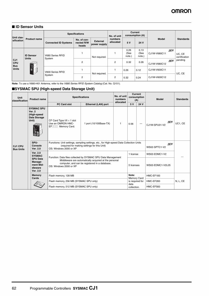
ID Sensor Units
Note: To use a V680-H01 Antenna, refer to the V680 Series RFID System Catalog (Cat. No. Q151).
SYSMAC SPU (High-speed Data Storage Unit)
Unit clas-sification
Product name
SpecificationsNo. of unit numbers allocated
Current consumption (A)
Model Standards
Connected ID SystemsNo. of con-nected R/W
heads
External power supply
5 V 24 V
CJ1 CPU Bus Units
ID Sensor Units
V680 Series RFID System
1
Not required.
10.26 (See note.)
0.13 (See note.)
CJ1W-V680C11 UC, CEcertification pending
2 2 0.32 0.26CJ1W-V680C12
V600 Series RFID System
1
Not required.
1 0.26 0.12 CJ1W-V600C11
UC, CE
2 2 0.32 0.24 CJ1W-V600C12
Unit classification
Product nameSpecifications No. of unit
numbers allocated
Current consumption
(A) Model Standards
PC Card slot Ethernet (LAN) port 5 V 24 V
CJ1 CPU Bus Units
SYSMAC SPU Ver. 2(High-speed Data Storage Unit) CF Card Type I/II × 1 slot
Use an OMRON HMC-EF@@@ Memory Card.
1 port (10/100Base-TX) 1 0.56 ---CJ1W-SPU01-V2
UC1, CE
SPU-Console Ver. 2.0
Functions: Unit settings, sampling settings, etc., for High-speed Data Collection Units (required for making settings for this Unit)
OS: Windows 2000 or XPWS02-SPTC1-V2
---
Ver. 2.0 SYSMAC SPU Data Manage-ment Mid-dleware Ver. 2.0
Function: Data files collected by SYSMAC SPU Data Management Middleware are automatically acquired at the personal computer, and can be registered in a database.
OS: Windows 2000 or XP
1 license WS02-EDMC1-V2
5 licenses WS02-EDMC1-V2L05
Memory Cards
Flash memory, 128 MB Note:Memory Card is required for data collection.
HMC-EF183
N, L, CEFlash memory, 256 MB (SYSMAC SPU only) HMC-EF283
Flash memory, 512 MB (SYSMAC SPU only) HMC-EF583
62 Programmable Controllers SYSMAC CJ1

Read and Understand this Catalog
Please read and understand this catalog before purchasing the products. Please consult your OMRON representative if you have any questions or comments.
Warranty and Limitations of Liability
WARRANTY
OMRON's exclusive warranty is that the products are free from defects in materials and workmanship for a period of one year (or other period if specified) from date of sale by OMRON.
OMRON MAKES NO WARRANTY OR REPRESENTATION, EXPRESS OR IMPLIED, REGARDING NON-INFRINGEMENT, MERCHANTABILITY, OR FITNESS FOR PARTICULAR PURPOSE OF THE PRODUCTS. ANY BUYER OR USER ACKNOWLEDGES THAT THE BUYER OR USER ALONE HAS DETERMINED THAT THE PRODUCTS WILL SUITABLY MEET THE REQUIREMENTS OF THEIR INTENDED USE. OMRON DISCLAIMS ALL OTHER WARRANTIES, EXPRESS OR IMPLIED.
LIMITATIONS OF LIABILITY
OMRON SHALL NOT BE RESPONSIBLE FOR SPECIAL, INDIRECT, OR CONSEQUENTIAL DAMAGES, LOSS OF PROFITS, OR COMMERCIAL LOSS IN ANY WAY CONNECTED WITH THE PRODUCTS, WHETHER SUCH CLAIM IS BASED ON CONTRACT, WARRANTY, NEGLIGENCE, OR STRICT LIABILITY.
In no event shall the responsibility of OMRON for any act exceed the individual price of the product on which liability is asserted.
IN NO EVENT SHALL OMRON BE RESPONSIBLE FOR WARRANTY, REPAIR, OR OTHER CLAIMS REGARDING THE PRODUCTS UNLESS OMRON'S ANALYSIS CONFIRMS THAT THE PRODUCTS WERE PROPERLY HANDLED, STORED, INSTALLED, AND MAINTAINED AND NOT SUBJECT TO CONTAMINATION, ABUSE, MISUSE, OR INAPPROPRIATE MODIFICATION OR REPAIR.
Application Considerations
SUITABILITY FOR USE
OMRON shall not be responsible for conformity with any standards, codes, or regulations that apply to the combination of products in the customer's application or use of the products.
Take all necessary steps to determine the suitability of the product for the systems, machines, and equipment with which it will be used.
Know and observe all prohibitions of use applicable to the products.
NEVER USE THE PRODUCTS FOR AN APPLICATION INVOLVING SERIOUS RISK TO LIFE OR PROPERTY WITHOUT ENSURING THAT THE SYSTEM AS A WHOLE HAS BEEN DESIGNED TO ADDRESS THE RISKS, AND THAT THE OMRON PRODUCTS ARE PROPERLY RATED AND INSTALLED FOR THE INTENDED USE WITHIN THE OVERALL EQUIPMENT OR SYSTEM.
PROGRAMMABLE PRODUCTS
OMRON shall not be responsible for the user’s programming of a programmable product, or any consequence thereof.
Disclaimers
CHANGE IN SPECIFICATIONS
Product specifications and accessories may be changed at any time based on improvements and other reasons.Consult with your OMRON representative at any time to confirm actual specifications of purchased products.
DIMENSIONS AND WEIGHTS
Dimensions and weights are nominal and are not to be used for manufacturing purposes, even when tolerances are shown.
PERFORMANCE DATA
Performance data given in this catalog is provided as a guide for the user in determining suitability and does not constitute a warranty. It may represent the result of OMRON's test conditions, and the users must correlate it to actual application requirements. Actual performance is subject to the OMRON Warranty and Limitations of Liability.

Authorized Distributor:
In the interest of product improvement, specifications are subject to change without notice.
Cat. No. P052-E1-07Printed in Japan
1208
OMRON CorporationIndustrial Automation Company
Regional HeadquartersOMRON EUROPE B.V.Wegalaan 67-69-2132 JD HoofddorpThe NetherlandsTel: (31)2356-81-300/Fax: (31)2356-81-388
OMRON ELECTRONICS LLCOne Commerce Drive Schaumburg, IL 60173-5302 U.S.A.Tel: (1) 847-843-7900/Fax: (1) 847-843-7787
OMRON ASIA PACIFIC PTE. LTD.No. 438A Alexandra Road # 05-05/08 (Lobby 2), Alexandra Technopark, Singapore 119967Tel: (65) 6835-3011/Fax: (65) 6835-2711
OMRON (CHINA) CO., LTD.Room 2211, Bank of China Tower, 200 Yin Cheng Zhong Road, PuDong New Area, Shanghai, 200120, ChinaTel: (86) 21-5037-2222/Fax: (86) 21-5037-2200
OMRON Industrial Automation Global: www.ia.omron.com
Control Devices Division H.Q.PLC DivisionShiokoji Horikawa, Shimogyo-ku,Kyoto, 600-8530 JapanTel: (81) 75-344-7084/Fax: (81) 75-344-7149
Note: Do not use this document to operate the Unit.