new developments at materials science diffractometer stress-spec at frm ii
9
NEW DEVELOPMENTS AT MATERIALS SCIENCE DIFFRACTOMETER STRESS-SPEC AT FRM II J. Rebelo Kornmeier 1 , M. Hofmann 2 , U. Garbe 3 , A. Ostermann 2 , C. Randau 4 , J. Repper 2 , W. Tekouo 5 , G.A. Seidl 2 , R.C. Wimpory 1 , R. Schneider 1 , H.G. Brokmeier 3,4 1 Helmholtz Zentrum Berlin für Mat. u. Energ., Glienicker Strae 100, D-14109 Berlin Wannsee, Germany 2 Forschungsneutronenquelle Heinz Maier-Leibnitz (FRM II), TU München, D-85747 Garching, Germany 3 GKSS-Forschungszentrum Geesthacht GmbH, Max-Planck-Strae 1, D-21502 Geesthacht, Germany 4 TU Clausthal, Adolph-Roemer-Strae 2A, D-38678 Clausthal-Zellerfeld, Germany 5 Inst. Werkzeugmaschinen und Betriebswissenschaften (iwb), TU München, D-85748 Garching, Germany Abstract The Materials Science Diffractometer STRESS-SPEC at the German neutron source FRM II is designed to meet the demands of non-destructive residual stress and texture determination by diffraction methods. With slit based optics used at STRESS-SPEC accurate residual stress determinations can be carried out even with small gauge volumes down to 1x1x1 mm‡ [1]. For measurements deep inside big components however (e.g. ship crankshafts, engines, etc), the spatial resolution is often limited by the instrumental set up. The slits, for example, have to be positioned relatively far away from the measurement position resulting in a blurred definition of the gauge volume due to divergence of the neutron beam. In addition the maximum of the neutron flux is found at the slit exit. The replacement of the primary slit system with a parabolic focussing guide enables both a better definition of the gauge volume and a maximum of neutron flux at the measurement position as the focal point of the guide is several centimetres away from the guide exit [2]. First test measurements of a prototype parabolic guide at STRESS-SPEC are in good agreement with corresponding simulations and are presented here as well as the simulations of an optimised multi-channel parabolic guide for STRESS-SPEC. Furthermore, we will show the enhancement of the capabilities by STRESS-SPEC in sample positioning using a robotic system. This system will be optional to the conventional goniometers (Eulerian cradles) on STRESS-SPEC and is optimised for sample weights of up to 60 kg, with a translation range and positioning accuracy down to –0,04 mm for residual stress determination and texture analysis. 209 Copyright ©JCPDS-International Centre for Diffraction Data 2009 ISSN 1097-0002 Advances in X-ray Analysis, Volume 52
Transcript of new developments at materials science diffractometer stress-spec at frm ii

NEW DEVELOPMENTS AT MATERIALS SCIENCE DIFFRACTOMETER
STRESS-SPEC AT FRM II
J. Rebelo Kornmeier1, M. Hofmann2, U. Garbe3, A. Ostermann2, C. Randau4, J. Repper2,
W. Tekouo5, G.A. Seidl2, R.C. Wimpory1, R. Schneider1, H.G. Brokmeier3,4
1Helmholtz Zentrum Berlin für Mat. u. Energ., Glienicker Straße 100, D-14109 Berlin Wannsee, Germany 2Forschungsneutronenquelle Heinz Maier-Leibnitz (FRM II), TU München, D-85747 Garching, Germany
3GKSS-Forschungszentrum Geesthacht GmbH, Max-Planck-Straße 1, D-21502 Geesthacht, Germany 4TU Clausthal, Adolph-Roemer-Straße 2A, D-38678 Clausthal-Zellerfeld, Germany
5Inst. Werkzeugmaschinen und Betriebswissenschaften (iwb), TU München, D-85748 Garching, Germany
Abstract
The Materials Science Diffractometer STRESS-SPEC at the German neutron source FRM II is
designed to meet the demands of non-destructive residual stress and texture determination by
diffraction methods.
With slit based optics used at STRESS-SPEC accurate residual stress determinations can be
carried out even with small gauge volumes down to 1x1x1 mm³ [1]. For measurements deep
inside big components however (e.g. ship crankshafts, engines, etc�), the spatial resolution is
often limited by the instrumental set up. The slits, for example, have to be positioned relatively
far away from the measurement position resulting in a blurred definition of the gauge volume due
to divergence of the neutron beam. In addition the maximum of the neutron flux is found at the
slit exit. The replacement of the primary slit system with a parabolic focussing guide enables both
a better definition of the gauge volume and a maximum of neutron flux at the measurement
position as the focal point of the guide is several centimetres away from the guide exit [2]. First
test measurements of a prototype parabolic guide at STRESS-SPEC are in good agreement with
corresponding simulations and are presented here as well as the simulations of an optimised
multi-channel parabolic guide for STRESS-SPEC.
Furthermore, we will show the enhancement of the capabilities by STRESS-SPEC in sample
positioning using a robotic system. This system will be optional to the conventional goniometers
(Eulerian cradles) on STRESS-SPEC and is optimised for sample weights of up to 60 kg, with a
translation range and positioning accuracy down to ±0,04 mm for residual stress determination
and texture analysis.
209Copyright ©JCPDS-International Centre for Diffraction Data 2009 ISSN 1097-0002Advances in X-ray Analysis, Volume 52

This document was presented at the Denver X-ray Conference (DXC) on Applications of X-ray Analysis. Sponsored by the International Centre for Diffraction Data (ICDD). This document is provided by ICDD in cooperation with the authors and presenters of the DXC for the express purpose of educating the scientific community. All copyrights for the document are retained by ICDD. Usage is restricted for the purposes of education and scientific research. DXC Website – www.dxcicdd.com
ICDD Website - www.icdd.com
Advances in X-ray Analysis, Volume 52

Introduction
Non-destructive residual stresses and texture analysis by means of diffraction methods has gained
worldwide significance in recent years. In order to cater for the development of these techniques
the new materials science diffractometer STRESS-SPEC has been installed for routine operations
since 2004 at the FRM II reactor source in Munich, Germany, with a flexible configuration and
high neutron flux at the sample position [1].
For the measurement of points deeply embedded inside complex components however the slit
based optics shows strong limitations. When the primary slit has to be positioned far away from
the scattering centre there is a poor definition of the nominal gauge volume, especially for the
vertical dimension (because of the use of vertical focussing monochromators to maximise
intensity). For example when measuring a large crank shaft from a diesel ship the slit distance to
scattering centre had to be 200 mm which resulted in a gauge height of 12 mm for the nominal
slit height of 2 mm. A multi-channel parabolic guide would improve the gauge definition at the
measuring position. Furthermore measurements of residual stress profiles or texture over large
components require a faster and accurate positioning and orientation of the components
concerning the neutron beam.
With complex components geometries the conventional positioning method shows its limitations.
In this case the adjustment of the components on the diffractometer and measurements at difficult
accessible points in the component can both be realized only insufficiently and/or slowly. A robot
system which permits tilting of large and heavy components in all directions in space due to its
flexibility (compare to the usual xyz translations) would simplify the measurements and
potentially reduced the measuring time significantly.
In this paper the developments of the STRESS-SPEC instrument will be described. A robotic arm
system and a multi-channel parabolic guide will improve the measurements in the following
aspects:
- robotic arm system for fast, accurate and flexible sample manipulation when measurements of
geometrically complex engineering components are necessary.
- muilti-channel parabolic guide to increase intensity and definition of gauge volume at
measuring position inside bulky components.
210Copyright ©JCPDS-International Centre for Diffraction Data 2009 ISSN 1097-0002Advances in X-ray Analysis, Volume 52

Robotic system
Strain and texture measurements in engineering components by neutron diffraction require
flexible, precise and fast sample manipulation with respect to the gauge volume location (position
and orientation). To determine the strain tensor at a particular position of a sample it is necessary
to measure the lattice spacing in typically three or more orientations from a gauge volume centred
on that point [3]. Texture analysis is also based on the ability to rotate the component around the
point of interest to many orientations with respect to the scattering vector to obtain detailed and
accurate pole figures. The present available sample positioning method at FRM II relies on a
combination of linear translation devices with Eulerian-cradles for rotation. The STRESS-SPEC
linear translation tables from �Huber� are able to move samples up to 300 kg with 10 m
accuracy over a wide range of ±110 mm movements in XY and 300 mm in Z. Two
Eulerian-cradles are available, a closed one with a small distance from the XYZ mounting table
to cradle centre between 39-64 mm. The second one is a quarter Eulerian-cradle with a distance
between the mounting table and cradle centre of 135 mm, where samples of up to 20 kg can be
mounted. Although the materials science diffractometer STRESS-SPEC is well equipped for
stress/texture measurements there are strong limitations for measurements within real engineering
components with complex geometries, such as turbine blades, crank shafts, gears, etc.
The desire of less restricted movement has lead to an approved project and acquisition of a
�Staeubli� serial six-axis robotic arm system offering full six degrees of freedom for sample
movement, with spatial positioning with an accuracy of the order of ±0,04 mm. Among others
this is realised by a laser tracker which allows the exact determination of the sample position
related to the neutron beam and therefore a accurate sample alignment. Therefore , this system
enables a better and faster sample positioning for complex and large samples geometries.
Samples with weights up to 60 kg can be handled.
Parabolic guide
In this study a comparison between Monte Carlo simulations, using the software package
McStas [4], and experimental measurements where the primary slit was replaced by a prototype
parabolic focusing guide was performed. The prototype parabolic guide was constructed by Swiss
Neutronics using borated float glass with an entrance dimensions of 10.6x21.2 mm2 and an exit
of 4x8 mm2 respectively and a length of L=1 m. The guide walls are coated with a super mirror
211Copyright ©JCPDS-International Centre for Diffraction Data 2009 ISSN 1097-0002Advances in X-ray Analysis, Volume 52
of m=3. The single crystal monochromator of Ge(311) at a take-off angle of 75,51° was used to
have a wavelength of 2.08 Å.
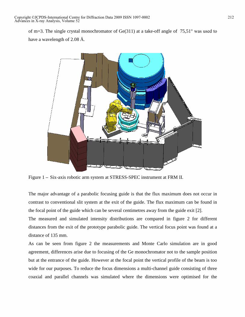
Figure 1 � Six-axis robotic arm system at STRESS-SPEC instrument at FRM II.
The major advantage of a parabolic focusing guide is that the flux maximum does not occur in
contrast to conventional slit system at the exit of the guide. The flux maximum can be found in
the focal point of the guide which can be several centimetres away from the guide exit [2].
The measured and simulated intensity distributions are compared in figure 2 for different
distances from the exit of the prototype parabolic guide. The vertical focus point was found at a
distance of 135 mm.
As can be seen from figure 2 the measurements and Monte Carlo simulation are in good
agreement, differences arise due to focusing of the Ge monochromator not to the sample position
but at the entrance of the guide. However at the focal point the vertical profile of the beam is too
wide for our purposes. To reduce the focus dimensions a multi-channel guide consisting of three
coaxial and parallel channels was simulated where the dimensions were optimised for the
212Copyright ©JCPDS-International Centre for Diffraction Data 2009 ISSN 1097-0002Advances in X-ray Analysis, Volume 52

STRESS-SPEC instrument set-up. These simulations are compared to simulations obtained for a
classical slit system (2x2 mm2), positioned at a distance corresponding to the guide exit.
Figure 2 � Comparison between measurements with a prototype parabolic guide and Monte
Carlo Simulations.
A schematic representation of the STRESS-SPEC instrument set-up where the primary slit
system is replaced by a multi-channel parabolic guide can be seen in figure 3.
213Copyright ©JCPDS-International Centre for Diffraction Data 2009 ISSN 1097-0002Advances in X-ray Analysis, Volume 52

sample
detector
monochromator
neutron guideL = 1.3 m d = 1.0 m
sample
detector
monochromator
neutron guideL = 1.3 m d = 1.0 m
Figure 3 - Schematic representation of STRESS-SPEC instrument set-up where the slit system is
replaced by a multi-channel parabolic guide (the guide is shown from the side).
The dimensions of the muti-channel parabolic guide were optimised to have a focus position at
110 mm after the guide exit. The neutron guide length is 1.3 m. The sample diameter was 5 mm.
The dimensions of the cross section of the entrance and the exit of the individual guides channels
can be seen in table 1.
Entrance Exit
Outer guide 30x30 mm2 5.8x2.1 mm2
Middle guide 15x30 mm2 3.9x2.1 mm2
Inner guide 7.5x30 mm2 2.1x 2.1 mm2
Table 1 - Dimensions of the entrance and exit cross sections of the individual channels which
forms the multi-channel parabolic guide.
The inner surfaces of the top and bottom walls of each channel are coated with super mirror with
m=3 whereas the outer surfaces as well as the side walls are absorbing. The side walls are
absorbing to increase lateral collimation and to define the horizontal gauge volume. The large
entrance dimension is necessary to accept the horizontal divergence of the Ge monochromator
and for the use of an optional, horizontal focussing Si-monochromator also available at STRESS-
SPEC. The results of Monte Carlo simulations for a conventional slit system and the optimised
multi-channel parabolic guide are compared in figure 4.
214Copyright ©JCPDS-International Centre for Diffraction Data 2009 ISSN 1097-0002Advances in X-ray Analysis, Volume 52

0
2
4
6
8
10
12
14
16
0 50 100 150 200 250 300
Distance Sample - Slit/Guide [mm]
FW
HM
[m
m]
.
Slit horiz.
Guide horiz.
Slit ver.
Guide ver.
Figure 4 � Comparison of Monte Carlo simulations for slit system and multi-channel parabolic
guide. The horizontal gauge volume of guide and slit are almost the same for this
configuration.
As can be seen in figure 4 at 110 mm after the guide exit there is a minimum in the vertical
FWHM (gauge volume definition) of the multi-channel parabolic guide compared with the slit
system. At this point the he FWHM for the guide the vertical direction is 2.4 mm instead of ~
6 mm for the slit, respectively. Figure 5 shows the Monte Carlo simulations of the corresponding
Debye-Scherrer cones at the detector. The detector is at 1 m distance from the sample position
and has the dimensions of 200x200 mm2. The diffraction peaks for a powder sample at 2=90°
were observed with the reference slit and the multi-channel parabolic guide, figure 5. A gain of
2.3 in efficiency is observed with the multi-channel parabolic guide without significant change in
the FWHM of the Debye-Scherrer cone. For shorter wavelength it is expected that the gauge
volume will increase slightly and the intensity gain will be reduced (i.e. to about a factor of 1.5
for = 1.6 Å).
A multi-channel parabolic guide is now under construction and will be tested soon.
215Copyright ©JCPDS-International Centre for Diffraction Data 2009 ISSN 1097-0002Advances in X-ray Analysis, Volume 52

Slit system
0500
100015002000250030003500400045005000550060006500
-0.1 -0.075 -0.05 -0.025 0 0.025 0.05 0.075 0.1
X [m]
0500
100015002000250030003500400045005000550060006500
-0.1 -0.075 -0.05 -0.025 0 0.025 0.05 0.075 0.1
X [m]
Multi-channel parabolic guide
Slit system
0500
100015002000250030003500400045005000550060006500
-0.1 -0.075 -0.05 -0.025 0 0.025 0.05 0.075 0.1
X [m]
0500
100015002000250030003500400045005000550060006500
-0.1 -0.075 -0.05 -0.025 0 0.025 0.05 0.075 0.1
X [m]
Multi-channel parabolic guide
Figure 5 - Diffraction peaks for a powder sample at 2=90° for the reference slit (top) and the
multi-channel parabolic guide (bottom).
Conclusions
In this paper a summary of the new upgrades of the STRESS-SPEC instrument at FRM II in
Munich, Germany has been presented:
- a novel and flexible approach for complex sample manipulation with a six-axis robotic
arm from �Staeubli�.
- A multi-channel parabolic guide to increase intensity and improve the definition of the
gauge volume in positions deeply embedded in complex engineering components.
Acknowledgements:
The authors would like to thank the �Bundesministerium für Bildung Forschung�, BMBF
03BR7CLA, for funding the new developments at instrument STRESS-SPEC.
References
[1] M. Hofmann, R. Schneider, G.A. Seidl, J. Rebelo-Kornmeier, R.C. Wimpory, U. Garbe and H.-G. Brokmeier,
Physica B, 385�386 (2006) 1035�1037
[2] T. Hils, P. Boeni, J. Stahn, Physica B, 350 (2004) 166-168
[3] M.T. Hutchings et al., Introduction to the characterization of residual stress by neutron diffraction, Taylor &
Francis Group, LLC, 2005
[4] K. Lefmann and K. Nielsen, Neutron News 10, (3), (1999), 20-23
216Copyright ©JCPDS-International Centre for Diffraction Data 2009 ISSN 1097-0002Advances in X-ray Analysis, Volume 52