NEW DESIGN OF GROUND FAULT PROTECTION
25
© Siemens AG 2018 All rights reserved. siemens.com/energy-management NEW DESIGN OF GROUND FAULT PROTECTION The 71st Annual Conference for Protective Relay Engineers
Transcript of NEW DESIGN OF GROUND FAULT PROTECTION

© Siemens AG 2018 All rights reserved. siemens.com/energy-management
NEW DESIGN OFGROUND FAULT PROTECTIONThe 71st Annual Conference for Protective Relay Engineers

2018-03-29Page 2
Why do we need ground fault protection?
• widely used to protect transmission anddistribution lines in case of ground faults
• can detect and isolate even high resistiveground faults which are not seen bydistance protection
• often combined with a directional elementand used in a teleprotection scheme
• equipped with phase selection alsosuitable for single pole tripping

2018-03-29Page 3
Basic principle of ground fault protection
CBA IIII ++=03• Ground fault protection is based on zero sequencecurrent
• Ground fault protection picks up if magnitude ofzero sequence current exceeds threshold:
thresholdI >|3| 0
3I0
Threshold
T 0
T - Delay
67N Pickup
67N Trip
2018-03-29Page 4
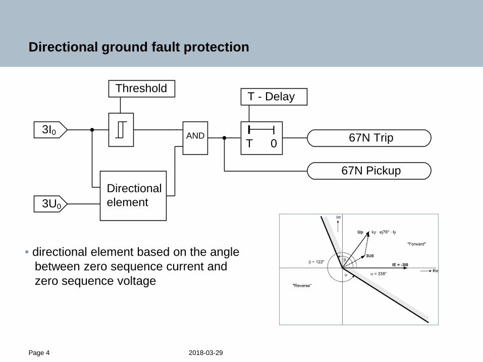
Directional ground fault protection
• directional element based on the anglebetween zero sequence current andzero sequence voltage
3I0
Threshold
T 0
T - Delay
67N Pickup
67N TripAND
3U0
Directionalelement

2018-03-29Page 5
Directional ground fault protection
• directional element based on the anglebetween negative sequence current andnegative sequence voltage
3I0
Threshold
T 0
T - Delay
67N Pickup
67N TripAND
3U2
Directionalelement
3I2

2018-03-29Page 6
Directional ground fault protection,suited for single pole tripping
• phase selection using the angle of zero sequence currentcompared to the angle of negative sequence current
3I0
Threshold
T 0
T - Delay
67N Pickup
AND
3U2Directionalelement
3I2
67N Trip Phase A
67N Trip Phase B
67N Trip Phase C
Phase selector

2018-03-29Page 7
Case 1:Wrong trip using zero sequence polarization
• wrong trip of directionalground fault protection
• Malaysia: 147 km line, 132 kV
• Figure left shows theimpedance trajectoriesin the complex plane
• BG fault, far away from thepolygons of distanceprotection in reverse direction

2018-03-29Page 8
Case 1:Wrong trip using zero sequence polarization
• Ground current iE exceeds the sensitivethreshold of 50A primary which leads to apickup of the ground fault protection
• Current of phase B is raising most whichis consistent with the pickup of phase B
• Changes of voltages after fault inception arenot very big but leaving enough quantity ofzero sequence voltage and negative sequencevoltage for the directional element

2018-03-29Page 9
Case 1:Wrong trip using zero sequence polarization
• Figure left is showing zero sequencequantities and negative sequencequantities in the phasor diagram
• zero sequence current is leadingzero sequence voltage byapproximately 100° forward fault
• negative sequence current is laggingnegative sequence voltage byapproximately 60° reverse fault
• zero sequence quantities are chosenbecause they are a little larger thannegative sequence quantities.

2018-03-29Page 10
Case 2: Wrong polarization due to an error ofvoltage transformer
• Figure left shows the impedancetrajectories in the complex plane
• It can be seen that the fault AGappears in reverse direction(green marked trajectory)

2018-03-29Page 11
Case 2: Wrong polarization due to an error ofvoltage transformer
• significant decrease in the voltage VAis a clear indication for a fault AG
• voltage VB shows an asymmetrydue to a voltage transformer error
• Wrong reading of VB has a majorimpact on the wrong directiondetermination using negative sequence
• Current IA is raising most which leadsto a pickup of ground fault protectionindicated by the signal “67G2”
• Signal “FSA” indicates that the relaydetects the faulted phase A butunfortunately the wrong directionindicated by the signal “32QF”
2018-03-29Page 12
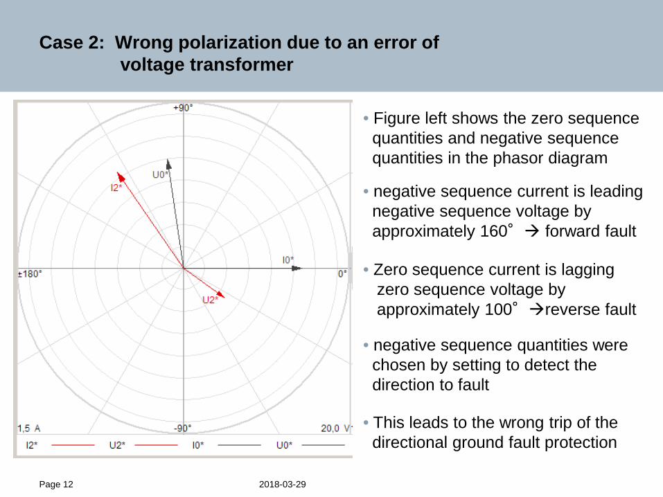
Case 2: Wrong polarization due to an error ofvoltage transformer
• Figure left shows the zero sequencequantities and negative sequencequantities in the phasor diagram
• negative sequence current is leadingnegative sequence voltage byapproximately 160° forward fault
• Zero sequence current is laggingzero sequence voltage byapproximately 100°reverse fault
• negative sequence quantities werechosen by setting to detect thedirection to fault
• This leads to the wrong trip of thedirectional ground fault protection

2018-03-29Page 13
Case 3: Wrong phase selection
• single phase high resistive fault BG close to Amarilis substation
• Due to this Amarilis was a weak infeed side with a transformer with a deltawinding on its 10 kV side
• At this time the line L-1120 was out of service

2018-03-29Page 14
Case 3: Wrong phase selection
• Figure left shows the impedancetrajectories in the complex plane
• fault BG appears on the real axisof the complex plane in forwarddirection (red marked trajectory)

2018-03-29Page 15
Case 3: Wrong phase selection
• Due to the transformer on theweak side all three phasecurrents are nearly in phase,producing a ground currentwhich is much bigger than eachsingle phase current
• Ground current causes a pickupindicated by the signal“67N Pickup”
• significant decrease in VB butthe faulted phase was notdetected
Instead of a single pole trip command for phase B a three pole trip was issuedindicated by the signal “Trip 3-pole”

2018-03-29Page 16
Case 3: Wrong phase selection
• reason for unselective trip was methodapplied to detect the faulted phase
• Method is based on the relation betweenangle of negative sequence current andangle of zero sequence current
• Zero sequence current should leadnegative sequence current byapproximately 120° for a fault BG
• But zero sequence current is leadingnegative sequence current byapproximately 60° only no clear indication for any type of fault
• Magnitude of the negative sequence currentis very small compared to the magnitude ofthe zero sequence current
L2-E
L3-E
L1-E
I2 = I0
I2 = a2*I0
I2 = a*I0
I0
I2

2018-03-29Page 17
New design of directional ground fault protection
• use all available information to detect faulted phase and direction to fault
3I0
Threshold
T 0
T - Delay
67N Pickup
AND
UADirectionalelement
UC
67N Trip Phase A
67N Trip Phase B
67N Trip Phase CPhase
selector
UB
IA
ICIB
AND
AND
AND

2018-03-29Page 18
Multi criteria phase selection
Criteria for phase selection
• Symmetrical components
• Impedance • Phase current• Delta current• Current sample• Current phasor• Phase voltage• Delta voltage• Voltage sample• Voltage phasorC
Criteria 2
Criteria 1
Criteria n
quality
weight 1
quality
weight 2
quality
weight n
Σ
AB
quality phase A
quality phase B
quality phase C

2018-03-29Page 19
Voltage magnitude criteria
quality
ULx [UN]
0.25
0.50
0.75
1.00
0.25 0.50 0.75 1.00
0.90 t/s0.14 0.15 0.16 0.17 0.18 0.19 0.20 0.21 0.22 0.23
U L1-E/ V
-50
0
t/s0.17 0.18 0.19 0.20 0.21 0.22 0.23 0.24 0.25 0.26
U L1-E/ V
-50
0
The lower the voltage, the higher the quality of the result.
2018-03-29Page 20
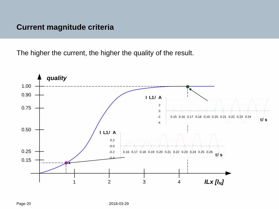
Current magnitude criteria
quality
ILx [IN]
0.25
0.50
0.75
1.00
1 2 3 4
0.90
0.15
t/s0.15 0.16 0.17 0.18 0.19 0.20 0.21 0.22 0.23 0.24
I L1/ A
-4
-2
0
2
t/s0.16 0.17 0.18 0.19 0.20 0.21 0.22 0.23 0.24 0.25 0.26
I L1/ A
-0.4
-0.2
-0.0
0.2
The higher the current, the higher the quality of the result.

2018-03-29Page 21
Impedance ratio criteria
The lower the ratio between the measured X and the parameterized X, thehigher the quality of the related loop.
quality
|XLx| / Par(X)
0.25
0.50
0.75
1.00
0.25 0.50 0.75 1.00
0.90
R
X
Z1
2018-03-29Page 22
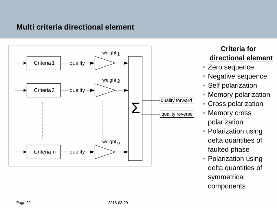
Multi criteria directional element
Criteria for directional element
• Zero sequence• Negative sequence• Self polarization• Memory polarization• Cross polarization• Memory cross
polarization• Polarization using
delta quantities of faulted phase
• Polarization using delta quantities of symmetrical components
Criteria 2
Criteria 1
Criteria n
quality
weight 1
quality
weight 2
quality
weight n
Σquality forward
quality reverse

2018-03-29Page 23
Multi-criteria directional element applied to case 2
• The binaries show that 7 criteria determine the fault in reverse direction
• Quality of reverse direction: >75%
• Quality of forward direction:<25%
Multi-criteria directionalelement can detect theright direction even ifsome criteria fail

2018-03-29Page 24
Conclusion
• It was shown that the reach of the classical impedance calculation method is significantly influenced by resistive faults on heavy loaded lines.
• Using the reactance method this reach error can be eliminated.
• Additionally a new method of loop selection was presented which is optimized for all network topologies.
• The same philosophy is applied for directional element where different algorithm are weighted dependent on network topology.

2018-03-29Page 25
Thank you for your attention!
Jörg BlumscheinPrincipal Key Expert ProtectionEM DG PRO LM&D PPM
Wernerwerkdamm 513629 Berlin
Phone: +49 (30) 386 20135Fax: +49 (30) 386 25158
E-mail:[email protected]
siemens.com/answers