
New aspects of geometric phases in experiments with ... Faculty of Physics ... The Berry phase is an...
15
IOP PUBLISHING JOURNAL OF PHYSICS A: MATHEMATICAL AND THEORETICAL J. Phys. A: Math. Theor. 43 (2010) 354015 (15pp) doi:10.1088/1751-8113/43/35/354015 New aspects of geometric phases in experiments with polarized neutrons S Sponar 1 , J Klepp 2 , K Durstberger-Rennhofer 1 , R Loidl 1 , S Filipp 3 , M Lettner 4 , R A Bertlmann 2 , G Badurek 1 , H Rauch 1 ,5 and Y Hasegawa 1 1 Atominstitut der ¨ Osterreichischen Universit¨ aten, TU-Wien, 1020 Vienna, Stadionallee 2, Austria 2 Faculty of Physics, University of Vienna, Boltzmanngasse 5, 1090 Vienna, Austria 3 Department of Physics, ETH Z¨ urich, Schafmattstr. 16, 8093 Z¨ urich, Switzerland 4 Max-Planck-Institut f¨ ur Quantenoptik, Hans-Kopfermann-Straße 1, 85748 Garching, Germany 5 Institut Laue-Langevin, BP 156, 38042 Grenoble Cedex 9, France E-mail: [email protected] Received 1 February 2010, in final form 7 May 2010 Published 12 August 2010 Online at stacks.iop.org/JPhysA/43/354015 Abstract Geometric phase phenomena have been observed with single neutrons in polarimeter and interferometer experiments. Interacting with static and time- dependent magnetic fields, the state vectors acquire a geometric phase tied to the evolution within spin subspace. In a polarimeter experiment the non-additivity of quantum phases for mixed spin input states is observed. In a Si perfect- crystal interferometer experiment appearance of geometric phases, induced by interaction with an oscillating magnetic field, is verified. The total system is characterized by an entangled state, consisting of neutron and radiation fields, governed by a Jaynes–Cummings Hamiltonian. In addition, the influence of the geometric phase on a Bell measurement, expressed by the Clauser–Horne– Shimony–Holt (CHSH) inequality, is studied. It is demonstrated that the effect of the geometric phase can be balanced by an appropriate change of Bell angles. PACS numbers: 03.75.Dg, 03.65.Vf, 03.65.Ud, 07.60.Ly, 42.50.Dv, 03.75.Be (Some figures in this article are in colour only in the electronic version) 1. Introduction The total phase acquired during an evolution of a quantum system generally consists of two components: the usual dynamical phase φ d and the geometric phase φ g . The dynamical phase, which depends on the dynamical properties, such as energy or time, is given by φ d =-1/¯ h H(t) dt . The peculiarity of the geometric phase lies in the fact that it does not depend on the dynamics of the system, but purely on the evolution path of the state. 1751-8113/10/354015+15$30.00 © 2010 IOP Publishing Ltd Printed in the UK & the USA 1
Transcript of New aspects of geometric phases in experiments with ... Faculty of Physics ... The Berry phase is an...

IOP PUBLISHING JOURNAL OF PHYSICS A: MATHEMATICAL AND THEORETICAL
J. Phys. A: Math. Theor. 43 (2010) 354015 (15pp) doi:10.1088/1751-8113/43/35/354015
New aspects of geometric phases in experiments withpolarized neutrons
S Sponar1, J Klepp2, K Durstberger-Rennhofer1, R Loidl1, S Filipp3,M Lettner4, R A Bertlmann2, G Badurek1, H Rauch1,5 and Y Hasegawa1
1 Atominstitut der Osterreichischen Universitaten, TU-Wien, 1020 Vienna, Stadionallee 2,Austria2 Faculty of Physics, University of Vienna, Boltzmanngasse 5, 1090 Vienna, Austria3 Department of Physics, ETH Zurich, Schafmattstr. 16, 8093 Zurich, Switzerland4 Max-Planck-Institut fur Quantenoptik, Hans-Kopfermann-Straße 1, 85748 Garching, Germany5 Institut Laue-Langevin, BP 156, 38042 Grenoble Cedex 9, France
E-mail: [email protected]
Received 1 February 2010, in final form 7 May 2010Published 12 August 2010Online at stacks.iop.org/JPhysA/43/354015
AbstractGeometric phase phenomena have been observed with single neutrons inpolarimeter and interferometer experiments. Interacting with static and time-dependent magnetic fields, the state vectors acquire a geometric phase tied to theevolution within spin subspace. In a polarimeter experiment the non-additivityof quantum phases for mixed spin input states is observed. In a Si perfect-crystal interferometer experiment appearance of geometric phases, induced byinteraction with an oscillating magnetic field, is verified. The total system ischaracterized by an entangled state, consisting of neutron and radiation fields,governed by a Jaynes–Cummings Hamiltonian. In addition, the influence ofthe geometric phase on a Bell measurement, expressed by the Clauser–Horne–Shimony–Holt (CHSH) inequality, is studied. It is demonstrated that the effectof the geometric phase can be balanced by an appropriate change of Bell angles.
PACS numbers: 03.75.Dg, 03.65.Vf, 03.65.Ud, 07.60.Ly, 42.50.Dv, 03.75.Be
(Some figures in this article are in colour only in the electronic version)
1. Introduction
The total phase acquired during an evolution of a quantum system generally consists of twocomponents: the usual dynamical phase !d and the geometric phase !g . The dynamicalphase, which depends on the dynamical properties, such as energy or time, is given by!d = !1/h
!"H(t)# dt . The peculiarity of the geometric phase lies in the fact that it does
not depend on the dynamics of the system, but purely on the evolution path of the state.
1751-8113/10/354015+15$30.00 © 2010 IOP Publishing Ltd Printed in the UK & the USA 1

J. Phys. A: Math. Theor. 43 (2010) 354015 S Sponar et al
Considering a spin 12 system, the geometric phase is given by minus half the solid angle
(!g = !"/2) of the curve traced out. Since its discovery by Berry in 1 [1] the topologicalconcept has been widely expanded and has undergone several generalizations.
The first experimental evidence of an adiabatic and cyclic geometric phase, commonlycalled the Berry phase, was achieved with photons in 1986 [2] and later with neutrons [3].Non-adiabatic [4] and non-cyclic [5] geometric phases as well as the off-diagonal case, whereinitial and final states are mutually orthogonal [6], have been considered. In addition to an earlyapproach by Uhlmann [7], an alternative concept of the geometric phase for mixed input statesbased on interferometry was developed by Sjoqvist et al [8]. Here, each eigenvector of theinitial density matrix independently acquires a geometric phase. The total mixed state phaseis a weighted average of the individual phase factors. This concept is of great significance forall experimental situations or technical applications in which pure state theories oversimplifythe description. Theoretical predictions have been tested using NMR and single-photoninterferometry [9, 10]. The idea has also been extended to the off-diagonal case [11, 12].
Neutron interferometry [13, 14] provides a powerful tool for investigations of quantumphenomena, particularly in the field of geometric phases, where the spatial as well as the spinorevolution leads to geometric phases. In the spatial case the two-dimensional Hilbert space isspanned by the two possible paths in the interferometer. It has been experimentally verified thata geometric phase for cyclic [15], as well as non-cyclic evolutions [16], can be induced. In thecase of spinor evolution, where the geometric phase is generated in spin subspace, the spinorrotations are carried out independently in each sub-beam due to the macroscopic separationof the partial beams in the interferometer [17]. Geometric phase effects are observed whenthe two sub-beams are recombined at the third plate of the interferometer followed by a spinanalysis. For instance in [18, 19], spin flippers in both beams clearly demarcate the separatecontributions of the dynamical and geometric phases acquired in the spin subspace.
The geometric phase in a single-particle system has been studied widely over the past twoand a half decades. Nevertheless its effect on entangled quantum systems is less investigated.The Berry phase is an excellent candidate to be utilized for logic gate operations in quantumcommunication [20] due to its robustness against noise. This has been tested recently usingsuperconducting qubits [21], and trapped polarized ultracold neutrons [22]. Entanglementis the basis for quantum communication and quantum information processing. Therefore,studies on systems combining both quantum phenomena, the geometric phase and quantumentanglement, are of great importance [23–25]. In the case of neutrons, entanglement isachieved between different degrees of freedom and not between different particles. Usingneutron interferometry, with spin polarized neutrons, single-particle entanglement betweenthe spinor and the spatial part of the neutron wavefunction [26], as well as full tomographicstate analysis [27], has already been accomplished.
In this paper we report on miscellaneous geometric phase phenomena in neutronpolarimetry as well as interferometry. In section 2 polarimetric measurements of noncyclicgeometric, dynamical and general phases are presented [28]. In particular, our experimentdemonstrates that the geometric and dynamical mixed state phases #g and #d , resulting fromseparate measurements, are not additive [29] in the sense that the total phase resulting from asingle, cumulative, measurement differs from #g + #d [30, 31]. Furthermore, we report onobservation and manipulation of the geometric phase generated in one of the Hilbert spacesin a spin-path entangled single-neutron system, namely the spin subspace. Section 3 focuseson the geometric phase generation due to time-dependent interaction with a radio-frequency(rf) field. Here the system is characterized by an entangled state, consisting of neutron andradiation field, governed by a Jaynes–Cummings Hamiltonian. In section 4 the influence of thegeometric phase on a spin-path entangled single-neutron system is described. We demonstrate
2
J. Phys. A: Math. Theor. 43 (2010) 354015 S Sponar et al
(a) (b)
(c)
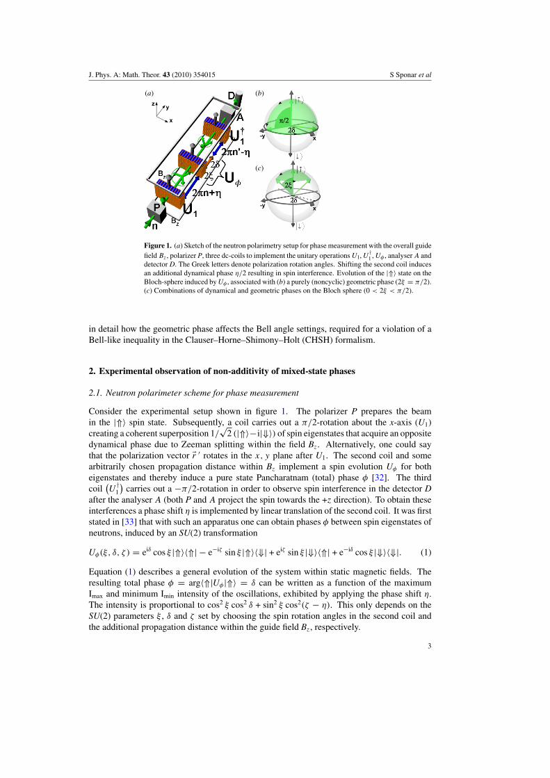
Figure 1. (a) Sketch of the neutron polarimetry setup for phase measurement with the overall guidefield Bz, polarizer P, three dc-coils to implement the unitary operations U1, U †
1 , U! , analyser A anddetector D. The Greek letters denote polarization rotation angles. Shifting the second coil inducesan additional dynamical phase $/2 resulting in spin interference. Evolution of the |$# state on theBloch-sphere induced by U! , associated with (b) a purely (noncyclic) geometric phase (2% = &/2).(c) Combinations of dynamical and geometric phases on the Bloch sphere (0 < 2% < &/2).
in detail how the geometric phase affects the Bell angle settings, required for a violation of aBell-like inequality in the Clauser–Horne–Shimony–Holt (CHSH) formalism.
2. Experimental observation of non-additivity of mixed-state phases
2.1. Neutron polarimeter scheme for phase measurement
Consider the experimental setup shown in figure 1. The polarizer P prepares the beamin the |$# spin state. Subsequently, a coil carries out a &/2-rotation about the x-axis (U1)creating a coherent superposition 1/
%2 (|$#!i|&#) of spin eigenstates that acquire an opposite
dynamical phase due to Zeeman splitting within the field Bz. Alternatively, one could saythat the polarization vector 'r ( rotates in the x, y plane after U1. The second coil and somearbitrarily chosen propagation distance within Bz implement a spin evolution U! for botheigenstates and thereby induce a pure state Pancharatnam (total) phase ! [32]. The thirdcoil
"U
†1
#carries out a !&/2-rotation in order to observe spin interference in the detector D
after the analyser A (both P and A project the spin towards the +z direction). To obtain theseinterferences a phase shift $ is implemented by linear translation of the second coil. It was firststated in [33] that with such an apparatus one can obtain phases ! between spin eigenstates ofneutrons, induced by an SU(2) transformation
U!(%, ', ( ) = ei' cos % |$#"$| ! e!i( sin % |$#"&| + ei( sin % |&#"$| + e!i' cos % |&#"&|. (1)
Equation (1) describes a general evolution of the system within static magnetic fields. Theresulting total phase ! = arg"$|U!|$# = ' can be written as a function of the maximumImax and minimum Imin intensity of the oscillations, exhibited by applying the phase shift $.The intensity is proportional to cos2 % cos2 ' + sin2 % cos2(( ! $). This only depends on theSU(2) parameters % , ' and ( set by choosing the spin rotation angles in the second coil andthe additional propagation distance within the guide field Bz, respectively.
3

J. Phys. A: Math. Theor. 43 (2010) 354015 S Sponar et al
A neutron beam with incident purity r ( = |'r (| along the +z-axis ('r ( = (0, 0, r ()) isdescribed by the density operator )in(r) = 1/2(11 + r (*z). For mixed input states, 0 ! r ( < 1.In this case [34] we find the intensity oscillations to be proportional to
I ) = 1 ! r (
2+ r ((cos2 % cos2 ' + sin2 % cos2(( ! $)). (2)
Considering again the maxima and minima of the intensity oscillations, one obtains the mixedstate phase
#(r () = arccos
$ %I)min
&I)n ! 1/2(1 ! r ()
'&r (
r (%1/2(1 + r () ! I
)max/I
)n
'+
%I)min/I
)n ! 1/2(1 ! r ()
'&r ( (3)
with a normalization factor I)n = 2I
)0
&(1 + r (). I
)0 is the intensity measured with U! = 11.
The noncyclic geometric phase is given by !g = !"/2, where " is the solid angleenclosed by an evolution path and its shortest geodesic closure on the Bloch sphere [5]: !g
and the total phase ! are related to the solid angle, which is parameterized by the polar andazimuthal angles 2% and 2' respectively (see, evolution paths depicted in figures 1(a) and (b))so that the pure state geometric phase in our case can be written as
!g = ! ! !d = '[1 ! cos(2%)], (4)
where !d is the dynamical phase. By a proper choice of 2% and 2', U! can be set togenerate purely geometric, purely dynamical or arbitrary combinations of both phases, e.g. infigures 1(b) and (c). For instance, we can choose to induce a purely geometric phase byselecting 2% to be equal to &/2.
The theoretical prediction for the mixed state phase is [8, 34]
# = arctan(r ( tan '). (5)
Note that equation (5) only depends on the parameter ' and the purity r (. Again, as can beseen also from equation (4), the parameter % only determines the portion of the dynamicalphase !d contained in the total phase !.
2.2. Experiment
To access equation (5) experimentally r ( has to be varied. In addition to the dc current, whicheffects the transformation U1, random noise is applied to the first coil, thereby changing Bx
in time. Neutrons, which are part of the ensemble )in(r(), arrive at different times at the coil
and experience different magnetic field strengths. We are left with the system in a mixed state'r =(0,!r, 0) where r <1 [35].
A neutron beam—incident from a pyrolytic graphite crystal—with a mean wavelength+ ) 1.98 A and spectral width ,+/+ ) 0.015 was polarized up to 99% by reflection from abent Co-Ti supermirror array. The final maximum intensity was about 150 counts s!1 at abeam cross-section of roughly 1 cm2. A 3He gas detector was used. Spin rotations around the+x-axis were implemented by the magnetic fields Bx from dc coils on frames with rectangularprofile (7 * 7 * 2 cm3). Bz was realized by two rectangular coils of 150 cm length inHelmholtz geometry. Low coil currents of about 2 A corresponding to field strengths of up to1 mT were required for the spin rotations and to prevent unwanted depolarization. The noisefrom a standard signal generator consisted of random dc offsets varying at a rate of 20 kHz.The experimental data shown in figure 2 reproduce well the r (-dependence predicted byequation (5).
4

J. Phys. A: Math. Theor. 43 (2010) 354015 S Sponar et al
(a) (b)
Figure 2. Mixed state phases determined from measured intensity oscillations using equation (5).Dynamical phase (a), geometric phase (b) versus input purity r for three evolution paths, i.e. threesettings of the second coil (angle 2% ) and flight distance after it (angle 2'). The legends indicateevolutions. The solid lines are theory curves using the rightmost data points as reference.
(a) (b)
Figure 3. Filled markers: measured total mixed state phase #tot versus purity r for two examplesof Utot associated with the total pure state phases !g + !d (see the text). Open markers: #g + #d
as calculated from measured data. The filled (empty) bars show measured mixed-state geometric(dynamical) phases. The solid and dotted theory curves assume either non-additivity or additivity,respectively.
2.3. Non-additivity
Our experiment focuses on a special property of the mixed state phase: its non-additivity.The Sjoqvist mixed state phase [8] is defined as a weighted average of phase factors ratherthan one of the phases. So it is true only for pure states that phases accumulated in separateexperiments can be added up to the usual total phase in the following sense. Suppose ageometric pure state phase !g is induced in the first, and a dynamic pure state phase !d in thesecond measurement. Applying (4) we can also choose a combination of the angles 2% and 2'leading to a transformation Utot, so that we measure the total pure state phase !g +!d in the thirdexperiment. However, the result of this latter experiment for the system initially in a mixedstate is #tot(r) = arctan[r tan(!g + !d)]. The total phase is not equal to #g(r) + #d(r), with#g(r) = arctan(r tan !g) and #d(r) = arctan(r tan !d). Two examples of data confirmingthis prediction are shown in figure 3.
3. Geometric phase generation in an oscillating magnetic field
The evolution of a system consisting of neutron, static magnetic field and quantized rf-field canbe described by a photon–neutron state vector, which is an eigenvector of a Jaynes–Cummings(J-C) Hamiltonian [36, 37], adopted for this particular physical configuration [38]. Since two
5

J. Phys. A: Math. Theor. 43 (2010) 354015 S Sponar et al
rf-fields (the reason for the second rf-field is explained in section 3.1), operating at frequencies- and -/2, are involved in the actual experiment, the modified corresponding J-C Hamiltonianis denoted as
HJ!C = ! h2
2m+2 ! µB0(r)*z + h
(-a†
-a- +-
2a†-/2a-/2
)(6)
+ µ
*B
(-)1 (r)%N-
"a†-+* + h.c.
#+
B(-/2)1 (r),
N-/2
"a†-/2+* + h.c.
#-
. (7)
with +* = 12 (*x +i*y). The first term accounts for the kinetic energy of the neutron. The second
term leads to the usual Zeeman splitting of 2|µ|B0. The third term adds the photon energy ofthe oscillating fields of the frequencies - and -/2, by the use of the creation and annihilationoperators a† and a. Finally, the last term represents the coupling between photons and theneutron, where N-j
=.a†-j
a-j
/represents the mean number of photons with frequencies -j
in the rf-field.The state vectors of the oscillating fields are represented by the coherent states |.#,
which are the eigenstates of a† and a. The eigenvalues of coherent states are complexnumbers, so one can write a|.# = .|.# =| .| ei!|.# with |.| =
%N. Neutrons interacting
with electromagnetic quanta are usually described by the ‘dressed-particle’ formalism [38],in analogy to the dressed-atom concept [39] developed nearly two decades before. Usingequation (7) one can define a total state vector including not only the neutron system |/N#,but also the two quantized oscillating magnetic fields:
|/tot# =| .-# , |.-/2# , |/N#. (8)
In a perfect Si-crystal neutron interferometer the wavefunction behind the first plate, actingas a beam splitter, is a linear superposition of the sub-beams belonging to the right (|I#)and the left path (|II#), which are laterally separated by several centimetres. The sub-beamsare recombined at the third crystal plate and the wavefunction in the forward direction thenreads |/N# - |I# + |II#, where |I# and |II# only differ by an adjustable phase factor ei0
(0 = !Npsbc+D, with the atom number density Nps in the phase shifter plate, the coherentscattering length bc, the neutron wavelength + and the thickness of the phase shifter plateD). By rotating the plate, 0 can be varied. This yields the well-known sinusoidal intensityoscillations of the two beams emerging behind the interferometer, usually denoted as O- andH-beams [13].
In our experiment, only the beam in path II is exposed to the rf-field of frequency -,resulting in a spin flip (see figure 4(a)). Interacting with a time-dependent magnetic field,the total energy of the neutron is no longer conserved after the spin flip [40–46]. Photons ofenergy h- are exchanged with the rf-field.
The time-dependent entangled state, which emerges from a coherent superposition of |I#and |II#, is expressed as
|/tot# =| .-# , |.-/2# , 1%2(|I# , |$# + ei-t ei0 |II# , ei!I |&#), (9)
for a more detailed description of the generation of |/tot# see [47].The effect of the first rf-flipper, placed inside the interferometer (path II), is described
by the unitary operator U (!I), which induces a spinor rotation from |$# to |&#, we denotedU (!I)|$# = ei!I |&#. The rotation axis encloses an angle !I with the x-direction, in the
6

J. Phys. A: Math. Theor. 43 (2010) 354015 S Sponar et al
(b)(a)
Figure 4. (a) The experimental apparatus for observation of geometric phase. The spin stateacquires a geometric phase 1 during the interaction with the two rf-fields and is flipped twice.Finally, the spin is rotated by an angle ' = &/2 (in the x, z plane), by a dc-spin turner, fora polarization analysis and count rate detection. (b) The Bloch-sphere description depicts theacquired geometric phase given by minus half the solid angle depending on the phase !I of therf-field. The effect of the beam block is explained in section 4.
rotating frame, and is determined by the oscillating magnetic field B(1) = B(-)rf cos(-t +!I) · y.
Formally one can insert a unity operator, given by 11 = U †(!0)U(!0), yielding
U (!I)|$# =
ei1
0 12 3U (!I)U
†(!0) U(!0)|$#2 30 111
= ei1 |&#, (10)
where U (!0) can be interpreted as a rotation from |$# to |&#, with the x-direction being therotation axis (!0 = 0), and U †(!0) describes a rotation about the same axis back to the initialstate |$#. Consequently, U(!I)U
†(!0) can be identified to induce the geometric phase 1 ,along the reversed evolution path characterized by !0 (|&# to |$#), followed by another pathdetermined by !I (|$# to |&#), see figure 4(b). In the rotating frame of [48] the two semi-greatcircles enclose an angle !I and the solid angle " = !2!I, yielding a pure geometric phase
1 = !"/2 = !I, (11)
which is depicted in figure 4(b). The entangled state, as described in [23], is represented by
|/Exp(1 )# = 1%2(|I# , |$# + |II# , ei1 |&#), (12)
including the geometric phase 1 = !I.
3.1. Experimental setup
As in a previous experiment [47], the spin in path |II# is flipped by an rf-flipper, whichrequires two magnetic fields: a static field B0 · z and a perpendicular oscillating fieldB(1) = B
(-)rf cos(-t + !I) · y satisfying the amplitude and frequency resonance condition
B(-)rf = &h
2 |µ|and - = 2|µ|B0
h
41 +
B21
16B20
5, (13)
where µ is the magnetic moment of the neutron and 2 denotes the time the neutron is exposedto the rf-field. The second term in - is due to the Bloch–Siegert shift [49]. The oscillatingfield is produced by a water-cooled rf-coil with a length of 2 cm, operating at a frequency of-/2& = 58 kHz. The static field is provided by a uniform magnetic guide field B
(-)0 . 2 mT,
produced by a pair of water-cooled Helmholtz coils.
7

J. Phys. A: Math. Theor. 43 (2010) 354015 S Sponar et al
= 0 = 0
= !/4 = !/4
= !/2 = !/2
15001500
10001000
50050015001500
10001000
500500
15001500
10001000
50050015001500
10001000
5005002!!0
= 3 = 3!/4!/4
Phase Shift, Phase Shift, " " (rad) (rad)
Inte
nsi
ty (
Neu
tro
ns
Inte
nsi
ty (
Neu
tro
ns /
60
sec )
60 s
ec)
O-BeamO-Beam
# $
# $
# $
# $
%!%!
0
!
3!/23!/2!!/2!/20
& &
+
& &
%Geo
met
ric
Ph
ase,
Geo
met
ric
Ph
ase,
&
& (r
ad)
(rad
)
r f Phase, f Phase, # # (rad) (rad) $ $
2!2!
%2!%2!
(a) (b)
Figure 5. (a) Typical interference patterns of the O-beam, when rotating the phase shifter plate(0 ). (b) A phase shift occurs by varying !I determining the geometric phase 1 . The sign of thegeometric phase 1 ± depends on the chosen initial polarization.
The O-beam passes the second rf-flipper, operating at -/2& = 29 kHz, which is half thefrequency of the first rf-flipper. The oscillating field is denoted as B
(-/2)rf cos((-/2)t + !II) · y,
and the strength of the guide field was tuned to B(-/2)0 . 1 mT in order to satisfy the frequency
resonance condition. This flipper compensates the energy difference between the componentsfrom the two interfering paths, by absorption and emission of photons of the energy E = h-/2.By choosing a frequency of -/2 for the second rf-flipper, the time dependence of the statevector is eliminated since both components acquire a phase e±i-/2(t+T ), depending on the spinorientation. Only a constant phase offset of e-T , where T is the propagation time between thecentres of the first and second flipper coils, remains in the stationary state vector. This phasecontribution, together with a dynamical phase contribution, resulting from Larmor precessionwithin the guide field regions B
(-)0 and B
(-/2)0 (pointing in + z-direction), is omitted here
because they remain constant during the entire experiment. Finally, the spin is rotated by anangle ' = &/2 (in the x, z plane) with a static field spin turner, and analysed due to the spin-dependent reflection within a Co-Ti multi-layer supermirror along the z-direction. Intensityoscillations in the forward direction (O-beam) are plotted in figure 5(a).
In a non-dispersive arrangement of the monochromator and the interferometer crystal theangular separation can be used such that only the spin-up (or spin-down) component fulfilsthe Bragg condition at the first interferometer plate (beam splitter). Therefore it is possibleto invert the initial polarization simply by rotating the interferometer by a few seconds of arc,which is expected to lead to an inversion of the geometric phase. Figure 5(b) shows a plot ofthe geometric phase ,1 ± versus !I, with !II = 0. As expected, the slope s is positive for initialspin-up orientation (s = 1.007(8)), and negative for the spin-down case (s = !0.997(5)), aspredicted in equation (11).
4. Geometric phase effects on a spin-path entangled system
In this section the influence of the geometric phase on a Bell measurement [50], expressed bythe CHSH [51] inequality, as proposed in [23], is discussed [52]. Following the notation given
8

J. Phys. A: Math. Theor. 43 (2010) 354015 S Sponar et al
in [23], the neutron’s wavefunction is defined via the tensor product of two Hilbert spaces: oneHilbert space is spanned by two possible paths in the interferometer given by |I# and |II#, andthe other one by spin-up and spin-down eigenstates, denoted as |$# and |&#, with respect to aquantization axis along a static magnetic field. For this experiment we focus on the neutronpart of equation (9) and omit all phases but the geometric phase 1 :
|/N(1 )# = 1%2(|I# , |$# + |II# , ei1 |&#). (14)
As in common Bell experiments, a joint measurement for spin and path is performed, therebyapplying the projection operators for the path
Pp±(!) = |±!#"±!|, (15)
with
|+!# = cos.1
2|I# + ei.2 sin
.1
2|II# and |!!# =! sin
.1
2|I# + ei.2 cos
.1
2|II#,
(16)
where .1 denotes the polar angle and .2 the azimuthal angle for the path. This is done inanalogous manner for the spin subspace with 31 as the polar angle and 32 as the azimuthalangle for the spin. Introducing the observables
Ap(!) = Pp+ (!) ! P
p!(!) and B
s(") = Ps
+(") ! Ps!(") (17)
one can define an expectation value for a joint measurement of spin and path along thedirections ! and ":
E(!,") = "/|Ap(!) , Bs(")|/# =! cos .1 cos 31 ! cos(.2 ! 32 + 1 ) sin .1 sin 31
= ! cos(.1 ! 31) for (.2 ! 32) = !1 . (18)
Next, a Bell-like inequality in CHSH-formalism [51] is introduced, consisting of fourexpectation values with the associated directions !, !( and ", "( for joint measurements ofspin and path, respectively
S(!,!(,","(, 1 ) = |E(!,") ! E(!,"() + E(!(,") + E(!(,"()|. (19)
Without loss of generality one angle can be eliminated by setting, e.g., ! = 0 (.1 = .2 = 0),which gives
S(!(,","(, 1 ) = |!sin .(1(cos(.(
2 ! 32 ! 1 ) sin 31 + cos(.(2 ! 3 (
2 ! 1 ) sin 3 (1)
! cos .(1(cos 31 + cos 3 (
1) ! cos 31 + cos 3 (1|. (20)
The boundary of equation (19) is given by the value 2 for any noncontextual hidden-variabletheories [53]. Keeping the polar angles .(
1, 31 and 3 (1 constant at the usual Bell angles .(
1 = &2 ,
31 = &4 , 3 (
1 = 3&4 (and azimuthal parts fixed at .(
2 = 32 = 3 (2 = 0) reduces S to
S(1 ) = |!%
2 !%
2 cos 1 |, (21)
where the familiar maximum value of 2%
2 is reached for 1 = 0. For 1 = & the value of Sapproaches zero.
4.1. Polar angle adjustment
Here we consider the case when the azimuthal angles are kept constant, e.g. .(2 = 32 = 3 (
2 = 0(.2 = 0), which is depicted in figure 6. The S-function reads
S(.(1,31,3
(1, 1 ) = |!sin .(
1(cos 1 sin 31 + cos 1 sin 3 (1)
! cos .(1(cos 31 + cos 3 (
1) ! cos 31 + cos 3 (1|. (22)
9

J. Phys. A: Math. Theor. 43 (2010) 354015 S Sponar et al
Figure 6. Bloch-sphere description includes the measurement settings of ! and "('), determiningthe projection operators, used for joint measurement of spin and path. ! is tuned by a combinationof the phase shifter (0 ) and the beam block, and " is adjusted by the angle '.
Valu
es (r
ad)
Valu
es(r
ad)
Geometric Phase Geometric Phase ! (rad)(rad)
3"-4
"-4
"-2 "0 5"-
4 3"-2
7"-4
-
0
"-4
"-2
3"-4
"
"-4
measuredmeasured
measuredmeasuredtheoretical predictions theoretical predictions
-
2"
5"-4
S V
alue
SVa
lue
S-value polar adjustedS-value polar adjusted
theoretical predictions theoretical predictions
2.5 (a) (b)
1.5
0.5
2
1
2 2
Geometric Phase Geometric Phase ! (rad)(rad)
3"-4
"-4
"-2 "0 5"-
4 3"-2
7"-4
2"
Figure 7. (a) Polar-adjusted S-values versus the geometric phase 1 with adapted Bell angles(31 and 3 (
1) according to the geometric phase 1 . (b) The corresponding modified Bell angles areplotted versus the geometric phase 1 .
The polar Bell angles 31, 3 (1 and .(
1 (.1 = 0), yielding a maximum S-value, can bedetermined, with respect to the geometric phase 1 , by calculating the partial derivatives (theextremum condition) of S in equation (22) (see [23] for more elaborated deduction). Thesolutions are given by
31 = arctan(cos 1 ), 3 (1 = & ! 31 and .(
1 = &
2, (23)
which are plotted in figure 7(b) (denoted as theoretical predictions). With these angles themaximal S decreases from S = 2
%2 for 1 : 0 / &
2 and touches at 1 = &2 even the limit of
the CHSH inequality S = 2. Within the interval 1 : &2 / & the value of S increases again
and returns to the familiar value S = 2%
2 at 1 = & .Experimentally, the probabilities of joint (projective) measurements are proportional to the
following count rates Nij with (i, j = +,!), detected after path (!) and spin (") manipulation:
E(!,") = N++(!,") ! N+!(!,") ! N!+(!,") + N!!(!,")
N++(!,") + N+!(!,") + N!+(!,") + N!!(!,"), (24)
with for example
N++(!,") = N++(!, (31, 0)) - "/N(1 )|P p+ (!) , P s
+ (31, 0)|/N(1 )#. (25)
In the case of N+!(!,") the count rate is given by N++"!, (30
1 , 0)#, where 30
1 = 31 +& . Theprocedure is applied to the count rates N+!(!,") and N!!(!,"). With these expectationvalues S can be calculated as defined in equation (19).
10

J. Phys. A: Math. Theor. 43 (2010) 354015 S Sponar et al
Projective measurements are performed on parallel planes defined by .2 = .(2 = 32 =
3 (2 = 0. For the path measurement the directions are given by ! : .1 = 0,.2 = 0, and
!( : .(1 = &/2, .(
2 = 0.The angle !, which corresponds to + z (and ! z for .0
1 = .1 +& = &,.2 = 0) is achievedby the use of a beam block which is inserted to the stop beam II (I) in order to measure along+ z (and ! z). The corresponding operators are given by
Pp+z(.1 = 0,.2 = 0) = |I#"I|
Pp!z
".0
1 = &,.2 = 0#
= |II#"II|.(26)
The angle !( is set by a superposition of equal portions of |I# and |II#, represented onthe equator of the Bloch sphere. The interferograms are achieved by a rotation of the phaseshifter plate, associated with a variation of the path phase 0 . All path scans are repeated atdifferent values of the spin analysis direction ' in order to determine 31 and 3 (
1 for a maximalviolation of the Bell-like CHSH inequality. The projective measurement for .(
1 = &/2,.(2 = 0
corresponds to a phase shifter position of 0 = 0 (and .(01 = .(
1 +& = 3&/2,.(2 = 0 to 0 = & ).
Projection operators read
Pp+x
(.(
1 = &
2,.(
2 = 0)
= 12((|I# + |II#)("I| + "II|)) (27)
Pp!x
4.(0
1 = 3&2
,.(2 = 0
5= 1
2((|I# ! |II#)("I| !" II|)). (28)
Using the measurement curves from equation (26) and equation (27), the S-value is calculatedaccording to equation (19) as a function of the parameters 31 and 3 (
1, which are variedindependently. The local maximum of S(3 (
1,31) is determined numerically and plotted infigure 7(a), with the corresponding values for 31 and 3 (
1 in figure 7(b).
4.2. Azimuthal angle adjustment
Next we discuss the situation where the standard maximal value S = 2%
2 can be achieved bykeeping the polar angles .(
1, 31 and 3 (1 constant at the Bell angles .(
1 = &2 , 31 = &
4 , 3 (1 = 3&
4 ,(.1 = 0), while the azimuthal parts, .(
2, 32 and 3 (2 (.2 = 0), are varied. A Bloch-sphere
description of this configuration can be seen in figure 8. The corresponding S function isdenoted as
S(.(2,32,3
(2, 1 ) =
66666!%
2 !%
22
(cos(.(2 ! 32 ! 1 ) + cos(.(
2 ! 3 (2 ! 1 ))
66666 . (29)
The maximum value 2%
2 is reached for
32 = 3 (2, and .(
2 ! 3 (2 = 1 (mod &). (30)
For convenience 32 = 0 is chosen.Experimentally the angle between the measurement planes is adjusted by one azimuthal
angle (.(2), which is deduced by phase shifter (0 ) scans.
For the spin measurement the directions are fixed and given by ": 31 = &/4, 32 = 0 and"(: 3 (
1 = 3&/4, 3 (2 = 0 (together with 30
1 = !3&/4, 3 (01 = !&/4. For the projective path
measurement the fixed directions read .1 = 0".0
1 = &#, for measurements with beam block,
and .(1 = &/2
".(0
1 = 3&&
2#. Phase shifter (0 ) scans are performed in order to determine .(
2
for a maximal violation of the Bell-like CHSH inequality yielding S = 2%
2.
11
J. Phys. A: Math. Theor. 43 (2010) 354015 S Sponar et al
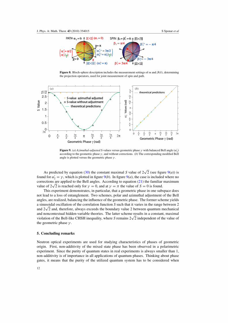
Figure 8. Bloch-sphere description includes the measurement settings of ! and "('), determiningthe projection operators, used for joint measurement of spin and path.
Geometric Phase Geometric Phase & (rad)(rad)
3!-4
!-4
!-2 !0 5!-
4 3!-2
7!-4
2!
Valu
es (r
ad)
Valu
es(r
ad)
'2
-
!-4
0
!-2
3!-4
!
5!-4
3!-2
7!-4 theoretical predictions theoretical predictions
S V
alue
SVa
lue
2.5
1.5
0.5
2
1
2 2
0
theoretical predictions theoretical predictions
S-value azimuthal adjustedS-value azimuthal adjusted S-value without adjustmentS-value without adjustment
2!
(a) (b)
Geometric Phase Geometric Phase & (rad)(rad)
3!-4
!-4
!-2 !0 5!-
4 3!-2
7!-4
2!
Figure 9. (a) Azimuthal-adjusted S-values versus geometric phase 1 with balanced Bell angle (.(2)
according to the geometric phase 1 , and without corrections. (b) The corresponding modified Bellangle is plotted versus the geometric phase 1 .
As predicted by equation (30) the constant maximal S value of 2%
2 (see figure 9(a)) isfound for .(
2 = 1 , which is plotted in figure 9(b). In figure 9(a), the case is included where nocorrections are applied to the Bell angles. According to equation (21) the familiar maximumvalue of 2
%2 is reached only for 1 = 0, and at 1 = & the value of S = 0 is found.
This experiment demonstrates, in particular, that a geometric phase in one subspace doesnot lead to a loss of entanglement. Two schemes, polar and azimuthal adjustment of the Bellangles, are realized, balancing the influence of the geometric phase. The former scheme yieldsa sinusoidal oscillation of the correlation function S such that it varies in the range between 2and 2
%2 and, therefore, always exceeds the boundary value 2 between quantum mechanical
and noncontextual hidden-variable theories. The latter scheme results in a constant, maximalviolation of the Bell-like CHSH inequality, where S remains 2
%2 independent of the value of
the geometric phase 1 .
5. Concluding remarks
Neutron optical experiments are used for studying characteristics of phases of geometricorigin. First, non-additivity of the mixed state phase has been observed in a polarimetricexperiment. Since the purity of quantum states in real experiments is always smaller than 1,non-additivity is of importance in all applications of quantum phases. Thinking about phasegates, it means that the purity of the utilized quantum system has to be considered when
12

J. Phys. A: Math. Theor. 43 (2010) 354015 S Sponar et al
inducing phases for further processing. Second, a technique for geometric phase generationhas been established by means of a precise spin manipulation due to interaction with rf-fields,in an interferometric setup. Applying the formalism of the Jaynes–Cumming Hamiltonianto the patterns in the observed outgoing beam of the interferometer, we find good agreementbetween experiment and theory. This technique is also applied to phase manipulations of thespin subspace in a triple-entanglement experiment with neutrons, which will be the topic ofa forthcoming publication. Finally, the effect of the geometric phase on the entanglement ofthe system has been analysed in detail using a Bell-like CHSH inequality. It is demonstrated,how the effects of the geometric phase on the outcome of a Bell measurement can be balancedby an appropriate change of Bell angles. Neutrons have proved to be a suitable quantumsystem for studying topological effects. Interferometric as well as polarimetric techniqueswill lead to further investigations, relevant for possible applications of the geometric phase.For instance, we are planning a polarimetric experiment, in which the geometric phase fornon-unitary evolutions is considered.
Acknowledgments
This work has been supported by the Austrian Science Foundation, FWF (P21193-N20, P-17803-N02 and P-20265). KDR would like to thank the FWF for funding her work by aHertha Firnberg Position (T389-N16).
References
[1] Berry M V 1984 Quantal phase factors accompanying adiabatic changes Proc. R. Soc. A 392 45[2] Tomita A and Chiao R Y 1986 Observation of Berry’s topological phase by use of an optical fiber Phys. Rev.
Lett. 57 937[3] Bitter T and Dubbers D 1987 Manifestation of Berry’s topological phase in neutron spin rotation Phys. Rev.
Lett. 59 251[4] Aharonov Y and Anandan J S 1987 Phase change during a cyclic quantum evolution Phys. Rev. Lett. 58 1593[5] Samuel J and Bhandari R 1988 General setting for Berry’s phase Phys. Rev. Lett. 60 2339[6] Manini N and Pistolesi F 2000 Off-diagonal geometric phases Phys. Rev. Lett. 85 3067[7] Uhlmann A 1991 A gauge field governing parallel transport along mixed states Lett. Math. Phys. 21 229[8] Sjoqvist E, Pati A K, Ekert A, Anandan J S, Ericsson M, Oi D K L and Vedral V 2000 Geometric phases for
mixed states in interferometry Phys. Rev. Lett. 85 2845[9] Du J, Zou P, Shi M, Kwek L C, Pan J W, Oh C H, Ekert A, Oi D K L and Ericsson M 2003 Observation of
geometric phases for mixed states using NMR interferometry Phys. Rev. Lett. 91 100403[10] Ericsson M, Achilles D, Barreiro J T, Branning D, Peters N A and Kwiat P G 2005 Measurement of geometric
phase for mixed states using single photon interferometry Phys. Rev. Lett. 94 050401[11] Filipp S and Sjoqvist E 2003 Off-diagonal geometric phase for mixed states Phys. Rev. Lett. 90 050403[12] Filipp S and Sjoqvist E 2003 Off-diagonal generalization of the mixed-state geometric phase Phys. Rev.
A 68 042112[13] Rauch H and Werner S A 2000 Neutron Interferometry (Oxford: Clarendon)[14] Rauch H, Treimer W and Bonse U 1974 Test of a single crystal neutron interferometer Phys. Lett. A 47 369[15] Hasegawa Y, Zawisky M, Rauch H and Ioffe A I 1996 Geometric phase in coupled neutron interference loops
Phys. Rev. A 53 2486[16] Filipp S, Hasegawa Y, Loidl R and Rauch H 2005 Noncyclic geometric phase due to spatial evolution in a
neutron interferometer Phys. Rev. A 72 021602[17] Wagh A G, Rakhecha V C, Fischer P and Ioffe A I 1998 Neutron interferometric observation of noncyclic phase
Phys. Rev. Lett. 81 1992[18] Wagh A G, Rakhecha V C, Summhammer J, Badurek G, Weinfurther H, Allman B E, Kaiser H, Hamacher K,
Jacobson D L and Werner S A 1997 Experimental separation of geometric and dynamical phases usingneutron interferometry Phys. Rev. Lett. 78 755
[19] Allman B E, Kaiser H, Werner S A, Wagh A G, Rakhecha V C and Summhammer J 1997 Observation ofgeometric and dynamical phases by neutron interferometry Phys. Rev. A 56 4420
13

J. Phys. A: Math. Theor. 43 (2010) 354015 S Sponar et al
[20] Nielsen M A and Chuang I L 2000 Quantum Computation and Quantum Information (Cambridge: CambridgeUniversity Press)
[21] Leek P J, Fink J M, Blais A, Bianchetti R, Goppl M, Gambetta J M, Schuster D I, Frunzio L, Schoelkopf R Jand Wallraff A 2007 Observation of Berry’s phase in a solid-state qubit Science 318 1889
[22] Filipp S, Klepp J, Hasegawa Y, Plonka-Spehr C, Schmidt U, Geltenbort P and Rauch H 2009 Experimentaldemonstration of the stability of Berry’s phase for a spin-1/2 particle Phys. Rev. Lett. 102 030404
[23] Bertlmann R A, Durstberger K, Hasegawa Y and Hiesmayr B C 2004 Berry phase in entangled systems: aproposed experiment with single neutrons Phys. Rev. A 69 032112
[24] Sjoqvist E 2000 Geometric phase for entangled spin pairs Phys. Rev. A 62 022109[25] Tong D M, Kwek L C and Oh C H 2003 Geometric phase for entangled states of two spin 1/2 particles in
rotating magnetic field J. Phys. A: Math. Gen. 36 1149[26] Hasegawa Y, Loidl R, Badurek G, Baron M and Rauch H 2003 Violation of a Bell-like inequality in single-
neutron interferometry Nature (London) 425 45[27] Hasegawa Y, Loidl R, Badurek G, Filipp S, Klepp J and Rauch H 2007 Evidence for entanglement and full
tomographic analysis of bell states in a single-neutron system Phys. Rev. A 76 052108[28] Klepp J, Sponar S, Hasegawa Y, Jericha E and Badurek G 2005 Noncyclic Pancharatnam phase for mixed state
SU(2) evolution in neutron polarimetry Phys. Lett. A 342 48[29] Singh K, Tong D M, Basu K, Chen J L and Du J F 2003 Geometric phases for nondegenerate and degenerate
mixed states Phys. Rev. A 67 032106[30] Klepp J, Sponar S, Filipp S, Lettner M, Badurek G and Hasegawa Y 2008 Observation of nonadditive mixed-state
phases with polarized neutrons Phys. Rev. Lett. 101 150404[31] Klepp J, Sponar S, Filipp S, Lettner M, Badurek G and Hasegawa Y 2009 Nonadditive mixed state phases
in neutron optics Foundations of Probability and Physics-5 (New York: American Institute of Physics)p 314
[32] Pancharatnam S 1956 Generalized theory of interference and its applications Proc. Indian Acad. Sci.44 247
[33] Wagh A G and Rakhecha V C 1995 On measuring the Pancharatnam phase: II. SU (2) polarimetry Phys. Lett.A 197 112
[34] Larsson P and Sjoqvist E 2003 Noncyclic mixed state phase in SU(2) polarimetry Phys. Lett. A 315 12[35] Bertlmann R A, Durstberger K and Hasegawa Y 2006 Decoherence modes of entangled qubits within neutron
interferometry Phys. Rev. A 73 022111[36] Jaynes E T and Cummings F W 1963 Comparison of quantum and semiclassical radiation theories with
application to the beam maser Proc. IEEE 51 89[37] Shore B W and Knight P L 1993 Topical review of the Jaynes–Cummings model J. Mod. Opt. 40 1195[38] Muskat E, Dubbers D and Scharpf O 1987 Dressed neutrons Phys. Rev. Lett. 58 2047[39] Cohen-Tannoudji C and Haroche S 1969 Interpretation quantique des diverses resonances observees lors de la
diffusion de photons optiques et de radiofrequence par un atome J. Physique 30 125[40] Alefeld B, Badurek G and Rauch H 1981 Observation of the neutron magnetic resonance energy shift Z. Phys.
B 41 231[41] Badurek G, Rauch H and Tuppinger D 1986 Neutron interferometric double-resonance experiment Phys. Rev.
A 34 2600[42] Gahler R and Golub R 1987 A neutron resonance spin echo spectrometer for quasi-elastic and inelastic scattering
Phys. Lett. A 123 43[43] Summhammer J 1993 Coherent multiphoton exchange between a neutron and an oscillating magnetic field
Phys. Rev. A 47 556[44] Golub R, Gahler R and Keller T 1994 A plane wave approach to particle beam magnetic resonance Am. J.
Phys. 62 9[45] Summhammer J, Hamacher K A, Kaiser H, Weinfurter H, Jacobson D L and Werner S A 1995 Multiphoton
exchange amplitudes observed by neutron interferometry Phys. Rev. Lett. 75 3206[46] Grigoriev S V, Kraan W H and Rekveldt M T 2004 Four-wave neutron-resonance spin echo Phys. Rev.
A 69 043615[47] Sponar S, Klepp J, Loidl R, Filipp S, Badurek G, Hasegawa Y and Rauch H 2008 Coherent energy manipulation
in single-neutron interferometry Phys. Rev. A 78 061604[48] Suter D, Mueller K T and Pines A 1988 Study of the Aharonov–Anandan quantum phase by NMR interferometry
Phys. Rev. Lett. 60 1218[49] Bloch F and Siegert A 1940 Magnetic resonance for nonrotating fields Phys. Rev. 57 522[50] Bell J S 1964 On the Einstein–Podolsky–Rosen paradox Physics 1 195
14

J. Phys. A: Math. Theor. 43 (2010) 354015 S Sponar et al
[51] Clauser J F, Horne M A, Shimony A and Holt R A 1969 Proposed experiment to test local hidden variabletheories Phys. Rev. Lett. 23 880
[52] Sponar S, Klepp J, Loidl R, Filipp S, Durstberger-Rennhofer K, Bertlmann R A, Badurek G, Rauch Hand Hasegawa Y 2010 Geometric phase in entangled systems: a single-neutron interferometer experimentPhys. Rev. A 81 042113
[53] Basu S, Bandyopadhyay S, Kar G and Home D 2001 Bell’s inequality for a single spin-1/2 particle and quantumcontextuality Phys. Lett. A 279 281
15