NEW APPLICATION OF RIGID POLYVINYL …ijet.feiic.org/journals/J-2006-V2015.pdfNEW APPLICATION OF...
13
International Journal of Engineering and Technology, Vol. 3, No. 2, 2006, pp.272-284 ISSN 1823-1039 2006 FEIIC 272 NEW APPLICATION OF RIGID POLYVINYL CHLORIDE PIPES IN SUB- SURFACE STORMWATER STORAGE-INFILTRATION SYSTEM A. A. N. AL-Hamati, A. H. Ghazali, T. A. Mohammed, J. Norzaie and M. R. Abdul Kadir Department of Civil Engineering, Universiti Putra Malaysia, Serdang, Malaysia Email: [email protected] ABSTRACT Polyvinyl chloride commonly abbreviated PVC is thermoplastic that is a polymer of vinyl chloride. Resins of polyvinyl chloride are hard, but with the addition of plasticizers a flexible plastic can be made. The good performance and low cost of rigid polyvinyl chloride commonly abbreviated PVC-U products make this polymer very suitable for many applications. Pipelines in water and sewer systems are the most common applications of PVC-U. Using PVC-U pipes in this study is a new and different from the common applications. The pipes will be used here to sustain axial loads for sub-surface stormwater storage and infiltration purposes. This study was conducted to investigate theoretically and experimentally the behavior and the capability of PVC-U pipes with and without existing of radial holes (orifices) in its wall to sustain the axial loads. Behavior of PVC-U pipes was investigated theoretically by modeling the pipe system using ANSYS Release 9.0 finite element code. The pipe was modeled using Solid 3-D brick element available in the element library of the ANSYS commercial package called SOLID45. The stress concentration around different orifice diameters at different locations from the pipe bottom subjected to an axial compression load of 3.4 kN are calculated. Furthermore, the behavior of PVC-U pipes specimens subjected to short-term uniaxial compression loads were experimentally investigated. Results of the load-displacement tests on pipes of different orifice locations were recorded. The experimental test results show that the PVC-U pipes have a tremendous capability of supporting the axial loads. Existing of radial orifices in the pipe wall will reduce its strength of supporting axial loads by approximately of 14%.. The pipe strength will be reduced also when the radial orifices becomes closer to the loaded pipe end. KEYWORDS: PVC-U, polyvinylchloride, pipes, uniaxial, stress, modeling INTRODUCTION PVC is one of the most common, widely used, and earliest plastics developed commercially. It is formed using two natural resources, salt (57%) and oil (43%) [1]. PVC was accidentally discovered in the 19th century. First in 1835 by Henri Victor Regnault and in 1872 by Eugen Baumann. On both occasions, the polymer appeared as a white solid inside flasks of vinyl chloride that had been left exposed to sunlight. In the early 20th century, the Russian chemist Ivan Ostromislensky and Fritz Klatte of the German chemical company Griesheim-Elektron both attempted to use PVC in commercial products, but difficulties in processing the rigid, sometimes brittle polymer blocked their efforts. In 1930, B.F. Goodrich developed a method to plasticize PVC by blending it with various additives. The result was a more flexible and more easily processed material that soon achieved widespread commercial use [2]. The long-term behavior of various PVC products application has a good record of long-term durability [1], [2],[3]. The range of PVC’s application demonstrates that this is the most versatile among thermoplastics [2]. The good performance and low cost of polyvinyl chloride products make this polymer very suitable for applications in buildings, mainly in exterior applications [1], [4]. PVC has many uses. For instance, rigid PVC (PVC-U) used as vinyl sheet piling, window profiles, doors, and pipelines in water and sewer systems. The common applications of the PVC-U pipes are for water supply, sewerage, or stormwater storage (e.g., pipe packages) purposes where the pipes installations usually in horizontal direction. Therefore, most of the literatures about PVC-U pipes are concerning on such applications. However, a very few researches found in which the PVC-U pipes were axially loaded for the purpose of crash energy absorption. The phenomenon of cylindrical tubes made from PVC-U material and various geometrical shapes collapsing in axial compression is considered one of the most efficient means of crash energy absorption. The collapsing behavior of PVC-U tubes under axial compression loads were investigated by some researchers for the purpose of crash energy absorption devices. For instance, Mamalis et al. [5] reported the crumpling of thin-walled PVC-U tubes when subject to
Transcript of NEW APPLICATION OF RIGID POLYVINYL …ijet.feiic.org/journals/J-2006-V2015.pdfNEW APPLICATION OF...

International Journal of Engineering and Technology, Vol. 3, No. 2, 2006, pp.272-284
ISSN 1823-1039 2006 FEIIC
272
NEW APPLICATION OF RIGID POLYVINYL CHLORIDE PIPES IN SUB-SURFACE STORMWATER STORAGE-INFILTRATION SYSTEM
A. A. N. AL-Hamati, A. H. Ghazali, T. A. Mohammed, J. Norzaie and M. R. Abdul Kadir
Department of Civil Engineering, Universiti Putra Malaysia, Serdang, Malaysia Email: [email protected]
ABSTRACT Polyvinyl chloride commonly abbreviated PVC is thermoplastic that is a polymer of vinyl chloride. Resins of polyvinyl chloride are hard, but with the addition of plasticizers a flexible plastic can be made. The good performance and low cost of rigid polyvinyl chloride commonly abbreviated PVC-U products make this polymer very suitable for many applications. Pipelines in water and sewer systems are the most common applications of PVC-U. Using PVC-U pipes in this study is a new and different from the common applications. The pipes will be used here to sustain axial loads for sub-surface stormwater storage and infiltration purposes. This study was conducted to investigate theoretically and experimentally the behavior and the capability of PVC-U pipes with and without existing of radial holes (orifices) in its wall to sustain the axial loads. Behavior of PVC-U pipes was investigated theoretically by modeling the pipe system using ANSYS Release 9.0 finite element code. The pipe was modeled using Solid 3-D brick element available in the element library of the ANSYS commercial package called SOLID45. The stress concentration around different orifice diameters at different locations from the pipe bottom subjected to an axial compression load of 3.4 kN are calculated. Furthermore, the behavior of PVC-U pipes specimens subjected to short-term uniaxial compression loads were experimentally investigated. Results of the load-displacement tests on pipes of different orifice locations were recorded. The experimental test results show that the PVC-U pipes have a tremendous capability of supporting the axial loads. Existing of radial orifices in the pipe wall will reduce its strength of supporting axial loads by approximately of 14%.. The pipe strength will be reduced also when the radial orifices becomes closer to the loaded pipe end. KEYWORDS: PVC-U, polyvinylchloride, pipes, uniaxial, stress, modeling
INTRODUCTION PVC is one of the most common, widely used, and earliest plastics developed commercially. It is formed using two natural resources, salt (57%) and oil (43%) [1]. PVC was accidentally discovered in the 19th century. First in 1835 by Henri Victor Regnault and in 1872 by Eugen Baumann. On both occasions, the polymer appeared as a white solid inside flasks of vinyl chloride that had been left exposed to sunlight. In the early 20th century, the Russian chemist Ivan Ostromislensky and Fritz Klatte of the German chemical company Griesheim-Elektron both attempted to use PVC in commercial products, but difficulties in processing the rigid, sometimes brittle polymer blocked their efforts. In 1930, B.F. Goodrich developed a method to plasticize PVC by blending it with various additives. The result was a more flexible and more easily processed material that soon achieved widespread commercial use [2]. The long-term behavior of various PVC products application has a good record of long-term durability [1], [2],[3]. The range of PVC’s application demonstrates that this is the most versatile among thermoplastics [2]. The good performance and low cost of polyvinyl chloride products make this polymer very suitable for applications in buildings, mainly in exterior applications [1], [4]. PVC has many uses. For instance, rigid PVC (PVC-U) used as vinyl sheet piling, window profiles, doors, and pipelines in water and sewer systems. The common applications of the PVC-U pipes are for water supply, sewerage, or stormwater storage (e.g., pipe packages) purposes where the pipes installations usually in horizontal direction. Therefore, most of the literatures about PVC-U pipes are concerning on such applications. However, a very few researches found in which the PVC-U pipes were axially loaded for the purpose of crash energy absorption. The phenomenon of cylindrical tubes made from PVC-U material and various geometrical shapes collapsing in axial compression is considered one of the most efficient means of crash energy absorption. The collapsing behavior of PVC-U tubes under axial compression loads were investigated by some researchers for the purpose of crash energy absorption devices. For instance, Mamalis et al. [5] reported the crumpling of thin-walled PVC-U tubes when subject to
International Journal of Engineering and Technology, Vol. 3, No. 2, 2006, pp.272-284
ISSN 1823-1039 2006 FEIIC
273
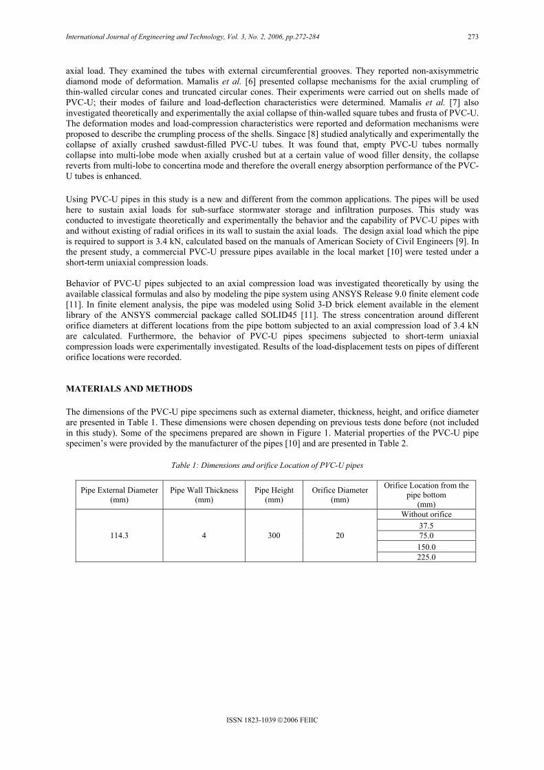
axial load. They examined the tubes with external circumferential grooves. They reported non-axisymmetric diamond mode of deformation. Mamalis et al. [6] presented collapse mechanisms for the axial crumpling of thin-walled circular cones and truncated circular cones. Their experiments were carried out on shells made of PVC-U; their modes of failure and load-deflection characteristics were determined. Mamalis et al. [7] also investigated theoretically and experimentally the axial collapse of thin-walled square tubes and frusta of PVC-U. The deformation modes and load-compression characteristics were reported and deformation mechanisms were proposed to describe the crumpling process of the shells. Singace [8] studied analytically and experimentally the collapse of axially crushed sawdust-filled PVC-U tubes. It was found that, empty PVC-U tubes normally collapse into multi-lobe mode when axially crushed but at a certain value of wood filler density, the collapse reverts from multi-lobe to concertina mode and therefore the overall energy absorption performance of the PVC-U tubes is enhanced. Using PVC-U pipes in this study is a new and different from the common applications. The pipes will be used here to sustain axial loads for sub-surface stormwater storage and infiltration purposes. This study was conducted to investigate theoretically and experimentally the behavior and the capability of PVC-U pipes with and without existing of radial orifices in its wall to sustain the axial loads. The design axial load which the pipe is required to support is 3.4 kN, calculated based on the manuals of American Society of Civil Engineers [9]. In the present study, a commercial PVC-U pressure pipes available in the local market [10] were tested under a short-term uniaxial compression loads. Behavior of PVC-U pipes subjected to an axial compression load was investigated theoretically by using the available classical formulas and also by modeling the pipe system using ANSYS Release 9.0 finite element code [11]. In finite element analysis, the pipe was modeled using Solid 3-D brick element available in the element library of the ANSYS commercial package called SOLID45 [11]. The stress concentration around different orifice diameters at different locations from the pipe bottom subjected to an axial compression load of 3.4 kN are calculated. Furthermore, the behavior of PVC-U pipes specimens subjected to short-term uniaxial compression loads were experimentally investigated. Results of the load-displacement tests on pipes of different orifice locations were recorded. MATERIALS AND METHODS The dimensions of the PVC-U pipe specimens such as external diameter, thickness, height, and orifice diameter are presented in Table 1. These dimensions were chosen depending on previous tests done before (not included in this study). Some of the specimens prepared are shown in Figure 1. Material properties of the PVC-U pipe specimen’s were provided by the manufacturer of the pipes [10] and are presented in Table 2.
Pipe External Diameter (mm)
Pipe Wall Thickness (mm)
Pipe Height (mm)
Orifice Diameter (mm)
Orifice Location from the pipe bottom
(mm) Without orifice
37.5 75.0 150.0
114.3
4 300 20
225.0
Table 1: Dimensions and orifice Location of PVC-U pipes

International Journal of Engineering and Technology, Vol. 3, No. 2, 2006, pp.272-284
ISSN 1823-1039 2006 FEIIC
274
A hand hydraulic pump was used to apply the axial loads on the PVC-U pipe specimens and a hydraulic pressure gage was connected to the pump by the gauge adapter. A hydraulic cylinder with maximum capacity of 50 ton was connected to the pump by high-pressure hydraulic hose. The axial loading from zero up to specimen failure was applied on the PVC-U pipe specimens, which bounded by free movement steel plate from the bottom and fixed steel plate at the top (Figure 2). Dial gage attached to the lower steel plate to record the axial displacements of the specimens. The strain gages attached at different locations of the pipe specimens to determine the stress concentration and distribution along the pipes. The strain gages were connected to the strain-gage data logger to printout the strains readings during the tests (strain results not included in this study) (Figure 3).
Table 2: Properties of PVC-U pipes
Property Unit Value Specific Gravity - 1.42 Hardness Rockwell R 120 Water Absorption mg/cm2 0.05 Tensile Strength MPa 45 Elongation at Break % 80 Compressive Strength MPa 66 Modulus of Elasticity MPa 2700 Izod Impact Strength kJ/m2 6 Poisson’s Ratio - 0.37
Figure 1: Pipes specimens prepared for test

International Journal of Engineering and Technology, Vol. 3, No. 2, 2006, pp.272-284
ISSN 1823-1039 2006 FEIIC
275
CLASSICAL FORMULAS AND FINITE ELEMENT MODELING Young and Budyanas [12] presented many classical formulas for thin-walled pressure vessels for different cases to determine the membrane stresses and displacements. The closest case found may be applicable to the pipe test of this study is the formula for prediction the stress concentration (maximum stress) around the radial hole in a hollow circular tube subject to axial tension load to predict the maximum stress around the hole in the pipe wall (Figure 4) as follow:
)(4
22maxdD
PKt
−π=σ (1)
where σmax = the maximum stress around the orifice or axial stress (σz) P = axial load on the pipe, kN D = external pipe diameter, m d = internal pipe diameter, m Kt = stress concentration factor
Figure 3: Measuring specimen axial displacements and strains
Figure 2: Experimental testing setup

International Journal of Engineering and Technology, Vol. 3, No. 2, 2006, pp.272-284
ISSN 1823-1039 2006 FEIIC
276
The axial load of 3.4 kN was applied on all the pipe specimens and the maximum stresses given by Equation (1) for different orifice diameter are calculated and presented in Table 3.
3
4
2
321222
+
+
+=
DrC
DrC
DrCCKt
(2)
for 9.0≤Dd and 45.02
≤Dr
where
000.31 =C , 2
2 379.4529.1773.2
−+=
Dd
DdC ,
2
3 781.22782.12421.0
+−−=
Dd
DdC , and
2
007.40678.16841.164
−+=
Dd
DdC
r = radius of the hole (orifice) in the pipe wall, m The maximum stress around the orifice was calculated with different orifice diameter using Equation (1). In addition, the FEA technique is used to analyze the pipe with orifice for two reasons;
- Equation (1) is used to predict the maximum stress at the middle of the pipe height and it doesn’t indicate the effect of the orifice location along the pipe height.
- To make sure the suitability of Equation (1) to predict the stress concentration around the orifice of the pipe subjected to axial compression load, because this equation applicable for circular shaft subject to axial tension load.
Axial loading of the PVC-U pipes was simulated using ANSYS Release 9.0 finite element code. In the analysis the pipe bottom was fixed in all directions (x, y and z) at one end (at the bottom) and uniformly distributed load was applied at the other end (Figure 5). The pipe was modeled using Solid 3-D brick element available in the element library of the ANSYS commercial package called SOLID45 [11]. The entire pipe geometry is modeled with a relatively fine mesh to avoid distorted aspect ratios as shown in Figure 5. The stress concentration around different orifice diameters at different locations from the pipe bottom of 300 mm height subjected to an axial compression load of 3.4 kN are calculated using the classical formula (Equation (1)) and the FEA technique and the results are presented in Table 3.
p
2r
d
D
Figure 4: Radial holes in a hollow circular tube subject to axial tension load [12]

International Journal of Engineering and Technology, Vol. 3, No. 2, 2006, pp.272-284
ISSN 1823-1039 2006 FEIIC
277
RESULTS AND DISCUSSION Theoretical Results The behavior of the pipes under an axial uniform compression load is investigated by using the FEA techniques. Pipe specimen of 114.3 mm external diameter, 4 mm wall thickness and 300 mm height subjected to an axial compression load of 3.4 kN. The stresses and displacements were determined and illustrated by the Figures 6 and 7. Figure 6 shows that, the vertical stress distribution σz is approximately constant along the pipe height (approximately 2306 kN/m2) but a maximum stress of 3532 kN/m2 developed at the external wall of the pipe bottom and a minimum stress of 1326 kN/m2 at the internal wall of pipe bottom. Due to the stress concentration around the external wall of the pipe bottom, the failure of the pipe is expected to occur at this location as local buckling. This result was verified by the experimental tests of the pipe specimens and was found that most of specimens failed at the pipe bottom as local buckling (Figure 11).
Figure 5: Finite element modeling of pipe specimens
x y
z

International Journal of Engineering and Technology, Vol. 3, No. 2, 2006, pp.272-284
ISSN 1823-1039 2006 FEIIC
278
The axial displacements ∆z of the pipe wall is shown in Figure 7(a). Figure 7(b) and Figure 7(c) shows the radial displacements ∆x in the pipe wall (x direction). The values of 0.27 mm and 0.02mm as maximum axial and radial displacements respectively were developed. The radial displacement is in the direction outward of the pipe center and Figure 7(c) shows the pipe position before (dashed line) and after the applying the load.
Figure 6: Vertical stress distribution along the pipe wall height, σz
Figure 7: Axial and radial displacements in the pipe wall
(a)
(b) (c)

International Journal of Engineering and Technology, Vol. 3, No. 2, 2006, pp.272-284
ISSN 1823-1039 2006 FEIIC
279
Equation (1) results were found in a good agreement with the FEA when the location of the orifice was at the middle of the pipe height. For the orifice with 20 mm diameter and 300 mm pipe height, the equation gives values of the stress concentration more than the FEA when the orifice location at or below the middle of the pipe height and lower values than FEA when the orifice location above the middle of the pipe height (Table 3) but it gives higher values for all the orifice locations with 10 mm diameter. From the differences between the FEA and Equation (1) for all the cases shown in Table 3, it is concluded that, the equation can used for the prediction of the stress concentration around the orifice for other cases may be needed for the design purposes. The values of the stress concentration factors Kt for all the cases were found more than 3 (Table 3), that is mean the normal stress will increase at lest three times (Equation (1)) when there is an orifice in the pipe wall. Therefore, it is preferable to avoid the orifice in the pipe wall if it’s not important. To understand the behavior of the pipes subjected to an axial uniform compression load and containing orifices on the pipe wall, the FEA used for some selected cases. Orifice with 20 mm diameter and different locations (Table 3) was chosen and the stress concentration around the orifice and the stress distribution along the pipe wall was illustrated by Figures 8-10. Figure 8 shows the vertical stress distribution σz along the pipe wall and around the orifice when the orifice at different locations from the pipe bottom. It is obvious that, the values of the stress around the orifice decreased as the orifice location far from the applied load. When the orifice location at 37.5 mm from the pipe bottom (Figure 8 (a)) the maximum stress was 7554 kN/m2 but when changing the location at 225mm from the pipe bottom (Figure 8 (d)) the stress increased to 8149 kN/m2.
Pipe External Diameter
(mm)
Pipe Wall Thickness
(mm)
Orifice Diameter
(mm)
Orifice Location
(mm)
Stress concentration
factor Kt
Classical Formula Stress
(kN/m2)
Ansys (FEA) Stress
(kN/m2)
Abs. Diff. (%)
37.5 3.091 7546 7404 1.88
75.0 3.091 7546 7323 2.96 150.0 3.091 7546 7396 1.99
10
225.0 3.091 7546 7413 1.76 37.5 3.286 8022 7554 5.83 75.0 3.286 8022 7761 3.25 150.0 3.286 8022 8006 0.20
20
225.0 3.286 8022 8149 1.58 37.5 3.576 8730 7665 12.20 75.0 3.576 8730 8235 5.67 150.0 3.576 8730 8589 1.62
114.3
4
30
225.0 3.576 8730 8975 2.81
Table 3: Stress Concentration around the Pipe Orifice

International Journal of Engineering and Technology, Vol. 3, No. 2, 2006, pp.272-284
ISSN 1823-1039 2006 FEIIC
280
Figure 9 shows the stress distribution σz along the pipe and around the orifice with 20 mm diameter and at location of 75 mm from the pipe bottom. The maximum stress of 7761 kN/m2 was developed around the pipe orifice and in comparison with the stress in Figure 6 (same pipe without orifice) of 3532 kN/m2 developed at the pipe bottom, it obvious that, the orifice increased the maximum stress and change it’s location from the pipe bottom to the location around the orifice. Due to the stress concentration around the orifice the failure of the pipe is expected to be at the orifice location.
Figure 9: Stress concentration around the pipe orifice, σz
Figure 8: Stress concentration around the pipe orifice for different orifice locations,σz
(d)(c)
(b)(a)

International Journal of Engineering and Technology, Vol. 3, No. 2, 2006, pp.272-284
ISSN 1823-1039 2006 FEIIC
281
The vertical displacement ∆z is slightly increased to 0.273 mm (Figure 10 (a)) than the case when the pipe without orifice (Figure 7 (a)), and the radial displacement in the x-direction ∆x also slightly increased to 0.024 mm at the location near the orifice level (Figure 10 (c)).
Figure 10: Displacement along the pipe, ∆z and ∆x
(d)(c)
(b)(a)

International Journal of Engineering and Technology, Vol. 3, No. 2, 2006, pp.272-284
ISSN 1823-1039 2006 FEIIC
282
Experimental Results The behavior of the PVC-U pipes under uniaxial compression loads without orifice and with orifice of 20 mm diameter located in different locations from the pipe bottom was investigated. Load-displacement relationship for the pipe specimens was recorded. Figure 11 shows the shape of failure of the pipe specimen without orifices. The failure occurred as local buckling at the pipe bottom due to the concentration of the stress at this location. On the other hand, the failure of specimens provided by the orifices in different locations occurred at these orifice locations as shown in Figure 12 and Figure 13.
Figure 11: Shape of failure of pipe specimens without orifice
Figure 12: Failure of pipe specimen during the test

International Journal of Engineering and Technology, Vol. 3, No. 2, 2006, pp.272-284
ISSN 1823-1039 2006 FEIIC
283
Load-displacement relationship for the pipe specimens was recorded and presented in Figure 14. From this figure it can be concluded that, the PVC-U pipes have high strength for supporting axial loads and existing of pipe orifices will reduce the pipe strength by approximately 14%. For example, the maximum pipe strength without orifice was 73 kN this value reduced to 63 kN when the pipe provided by the orifices. The pipe strength will be reduced also when the radial orifices becomes closer to the loaded pipe end. For example, the maximum pipe strength for the specimen when the orifices located at 37.5 mm from the pipe bottom was 63 kN this value decreased to 59 kN when the orifices location changed to 225 mm from the pipe bottom.
Figure 13: Failure occurred at pipe specimen’s orifice
Figure 14: Load-displacement relation of the pipes with different orifice locations
0 1 2 3 4 5 6 7 80
10
20
30
40
50
60
70
80
Axial pipe displacement (mm)
Com
pres
sion
load
(kN
)
Orifice location from the pipe bottom, (mm)
Symbol
Without orifice ▲ 37.5 O 75.0 +
150.0 ∆ 225.0 □

International Journal of Engineering and Technology, Vol. 3, No. 2, 2006, pp.272-284
ISSN 1823-1039 2006 FEIIC
284
CONCLUSIONS The axially loaded PVC-U pipes with and without existing of radial orifices at different locations in the pipe wall were investigated theoretically and experimentally to evaluate the behavior and the capability of the pipe to be used in sub-surface stormwater storage infiltration, which is required to support an axial load of 3.4 kN. Classical formulas found in a good agreement with the FEA for predicting the stress concentration around the pipe orifices when the location of the orifices was at the middle of the pipe height. From the differences between the FEA and classical formulas for all the cases shown in Table 3, it is concluded that, the equation can used for the prediction of the stress concentration around the orifice for other cases may be needed for the design purposes. Short-term axial compression tests of the specimens demonstrate that, the PVC-U pipes have a great capability to support an axial static load of much more than the design load (3.4 kN) and existing of pipe orifices will reduce the pipe strength by approximately 14%. In general it was found that, the pipe strength will be reduced also when the radial orifices becomes closer to the loaded pipe end. Thus, the pipe orifices should be far as possible from the loaded pipe end. REFERENCES [1] Dutta, P.K., and Vaidya, U. (2003) A study of the long-term applications of vinyl sheet piles. U.S. Army
Corps of Engineers, Engineer Research and Development Center, Cold Regions Research and Engineering Laboratory: 1-82.
[2] Titow, W.V. (1990) PVC plastics properties, processing, and applications. Elsevier science publishers LTD, England. 902 pp.
[3] Mersiowsky, D.I., Stegmann, I.R., Ejlertsson, J, and Svensson, B. (1999) Long-term behaviour of pvc products under soil-buried and landfill conditions - final report of the research project. Dept. of Waste Management, Technical University of Hamburg-Harburg, Germany and Dept. of Water and Environmental Studies, Linkpِing University, Sweden: 1-306.
[4] Reala, L.P., Pereira, A.R., and Gardetteb, J. (2002) Artificial accelerated weathering of poly (vinyl chloride) for outdoor applications: the evolution of the mechanical and molecular properties. Polymer Degradation and Stability, 82: 235–243.
[5] Mamalis, A.G., Manolakos, D.E., Viegelahn, G.L., Vaxevanidis, N.M. and Johnson, W. (1986) The inextensional collapse of grooved thin-walled cylinders of PVC under axial loading, Int. J. Impact Engng, 4 (1): 41-56.
[6] Mamalis, A.G., Manolakos, D.E., Viegelahn, G.L., Vaxevanidis, N.M. and Johnson, W. (1986) On the inextensional axial collapse of thin PVC conical shells, Int. J. Impact Engng, 4 (1): 41-56.
[7] Mamalis, A.G., Manolakos, D.E. and Viegelahn, G.L. (1989) The axial crushing of thin PVC tubes and frusta of square cross-section, Int. J. Impact Engng, 8 (3): 241-264.
[8] Singace, A.A. (2000) Collapse behaviour of plastic tubes filled with wood sawdust, Thin-Walled Structures, 37 (2): 163–187.
[9] American Society of Civil Engineers and the Water Environment Federation (ASCE). (1992) Design and construction of urban stormwater management systems. Manuals and Reports of Engineering Practice, No. 77, New York. 724 pp.
[10] Paling Industries Sdn Bhd., Malaysia (2005). http://www.paling.com.my. 21 November 2004. [11] ANSYS, Inc. (2004), Ansys Release 9.0 documentation. [12] Young, W.C. and Budyanas, R.G. (2002) Roark’s Formulas for Stress and Strain, 7th ed., McGraw Hill,
New York.