
Nevada Power Company and Sierra Pacific Power Company ...
62
Nevada Power Company and Sierra Pacific Power Company doing business as NV Energy GREENLINK WEST TRANSMISSION PROJECT PLAN OF DEVELOPMENT JULY 30, 2021 PREPARED BY: 6100 Neil Road Reno, NV 89520-0024 (775) 834-3528
Transcript of Nevada Power Company and Sierra Pacific Power Company ...

Nevada Power Company and Sierra Pacific Power Company doing business as NV Energy
GREENLINK WEST TRANSMISSION PROJECT
PLAN OF DEVELOPMENT
JULY 30, 2021
PREPARED BY:
6100 Neil Road Reno, NV 89520-0024
(775) 834-3528

This page intentionally left blank.

Greenlink West Transmission Project
Plan of Development Page i July 2021
TABLE OF CONTENTS
1.0 INTRODUCTION ........................................................................................................................... 1
2.0 BACKGROUND ............................................................................................................................. 2
3.0 APPLICANT’S PURPOSE AND NEED ...................................................................................... 9
4.0 PROJECT DESCRIPTION ........................................................................................................... 9
4.1 LOCATION ..................................................................................................................................... 9 4.1.1 Route Description ................................................................................................................. 9
4.2 PROJECT COMPONENTS ................................................................................................................. 9 4.2.1 Transmission Lines ............................................................................................................. 13 4.2.2 Substations .......................................................................................................................... 22 4.2.3 Telecommunications ........................................................................................................... 25
4.3 LAND/RIGHT-OF-WAY REQUIREMENTS ...................................................................................... 27 4.3.1 Temporary (Construction) ................................................................................................... 27 4.3.2 Permanent (Operations and Maintenance) .......................................................................... 30
4.4 CONSTRUCTION ACTIVITIES ........................................................................................................ 32 4.4.1 Transmission Line ............................................................................................................... 32 4.4.2 Substations .......................................................................................................................... 36 4.4.3 Telecommunications Facilities ........................................................................................... 36 4.4.4 Personnel ............................................................................................................................. 38 4.4.5 Equipment ........................................................................................................................... 38 4.4.6 Schedule .............................................................................................................................. 39
4.5 OPERATIONS AND MAINTENANCE ACTIVITIES ........................................................................... 39 4.6 REQUIRED AUTHORIZATIONS ...................................................................................................... 39
5.0 ENVIRONMENTAL COMPLIANCE ....................................................................................... 46
5.1 ENVIRONMENTAL COMPLIANCE MANAGEMENT ........................................................................ 46 5.2 ENVIRONMENTAL PROTECTION MEASURES ............................................................................... 46
5.2.1 General Measures ................................................................................................................ 47 5.2.2 Soil Disturbance .................................................................................................................. 47 5.2.3 Blasting ............................................................................................................................... 47 5.2.4 Stormwater Management .................................................................................................... 48 5.2.5 Noxious Weeds ................................................................................................................... 48 5.2.6 Vegetation ........................................................................................................................... 49 5.2.7 Water Features .................................................................................................................... 49 5.2.8 Wildlife and Sensitive Species ............................................................................................ 49 5.2.9 Cultural and Paleontological Resources .............................................................................. 50 5.2.10 Hazardous Materials and Waste .......................................................................................... 51 5.2.11 Air Quality .......................................................................................................................... 51 5.2.12 Fire Prevention and Response ............................................................................................. 52
6.0 REFERENCES .............................................................................................................................. 55
LIST OF FIGURES
NEVADA RENEWABLE ENERGY ZONES .............................................................. 5 FINAL PEIS SOLAR ENERGY ZONES IN NEVADA .............................................. 7 525 KV STEEL POLE H-FRAME TANGENT STRUCTURE.................................. 14

Greenlink West Transmission Project
Plan of Development Page ii July 2021
525 KV STEEL MONOPOLE TANGENT STRUCTURE ........................................ 15 525 KV STEEL MONOPOLE VERTICAL TANGENT STRUCTURE .................... 16 525 KV STEEL GUYED LATTICE TANGENT STRUCTURE ............................... 17 525 KV STEEL THREE-POLE DEAD-END/ANGLE STRUCTURE ...................... 18 525 KV SELF-SUPPORTING STEEL LATTICE DEAD-END/ANGLE
STRUCTURE .............................................................................................................. 19 345 KV STEEL POLE H-FRAME TANGENT STRUCTURE.................................. 20
345 KV STEEL THREE-POLE DEAD-END STRUCTURE..................................... 21
LIST OF TABLES
FINAL PEIS SOLAR ENERGY ZONES IN THE PROJECT AREA .......................... 8 PROJECT COMPONENTS ........................................................................................ 10 MICROWAVE RADIO FACILITIES ........................................................................ 26 AMPLIFIER SITES .................................................................................................... 27 TEMPORARY DISTURBANCE AREAS .................................................................. 27 PERMANENT DISTURBANCE AREAS .................................................................. 31 TYPICAL CONSTRUCTION EQUIPMENT............................................................. 38 POTENTIALLY REQUIRED PERMITS AND AUTHORIZATIONS ..................... 40 ENVIRONMENTAL COMPLIANCE TEAM ........................................................... 46
HAZARDOUS MATERIALS PROPOSED FOR PROJECT USE ............................ 51 EMERGENCY FIRE CONTACTS ............................................................................. 53
LIST OF ATTACHMENTS
ATTACHMENT A: ROUTING AND SITING STUDY (JUNE 2021) ATTACHMENT B: PROJECT MAPS ATTACHMENT C: SUBSTATION ARRANGEMENT DRAWINGS ATTACHMENT D: LEGAL DESCRIPTIONS

Greenlink West Transmission Project
Plan of Development Page iii July 2021
ACRONYMS AND ABBREVIATIONS
ACSR aluminum conductor steel reinforced BIA Bureau of Indian Affairs BLM United States Bureau of Land Management CCVT coupling capacitor voltage transformer C.F.R. Code of Federal Regulations Commission Public Utilities Commission of Nevada COM Plan Construction, Operation, and Maintenance Plan DoD United States Department of Defense DOE United States Department of Energy EIS Environmental Impact Statement FLPMA Federal Land Policy and Management Act kA kiloampere kcmil thousand circular mil kV kilovolt MVAR megavolt ampere (reactive) MW megawatts NAC Nevada Administrative Code NDEP Nevada Division of Environmental Protection NEPA National Environmental Policy Act of 1969 Nevada Power Nevada Power Company NITS Network Integration Transmission Service NPDES National Pollutant Discharge Elimination System NRS Nevada Revised Statutes NV Energy Nevada Power and Sierra Pacific both doing business as NV Energy OPGW optical ground wire PEIS Programmatic Environmental Impact Statement POD Plan of Development Project Greenlink West Transmission Project ROW Right-of-Way RPS renewable portfolio standard SHPO State Historic Preservation Office Sierra Pacific Sierra Pacific Power Company US United States USACE United States Army Corps of Engineers U.S.C. United States Code USEPA United States Environmental Protection Agency USFS United States Forest Service USFWS United States Fish and Wildlife Service

Greenlink West Transmission Project
Plan of Development Page iv July 2021
This page intentionally left blank.

Greenlink West Transmission Project
Plan of Development Page 1 July 2021
1.0 INTRODUCTION
Nevada Power Company (“Nevada Power”) and Sierra Pacific Power Company (“Sierra Pacific”) both doing business as NV Energy (hereinafter referred to as NV Energy) are submitting this Plan of Development (“POD”) to the United States Bureau of Land Management (“BLM”), along with a federal application for authorization to construct, operate and maintain a proposed system of new 525-kilovolt (“kV”), 345 kV, 230 kV, and 120 kV electric transmission facilities, hereafter referred to as the Greenlink West Transmission Project (“Project”).
The Project will involve the following components:
• Line terminal equipment at the existing Harry Allen 500 kV Substation (“Harry Allen Substation”)
• Existing Northwest 500/230 kV Substation (“Northwest Substation”) Expansion
• New Amargosa 500/230 kV Substation (“Amargosa Substation”)
• New Esmeralda 500/230 kV Substation (“Esmeralda Substation”)
• New 525 kV transmission lines:
− #5203 Esmeralda to Fort Churchill Line, Amargosa-Esmeralda 500 kV Line, and Amargosa-Northwest 500 kV Line (collectively referred to as the “Fort Churchill-Northwest Line” hereafter; 325 miles)
− Harry Allen-Northwest 500 kV Line (“Harry Allen-Northwest Line”; 33 miles)
• New Fort Churchill 500/345/230/120 kV Substation (“Fort Churchill Substation”)
• Line terminal equipment at the existing Comstock Meadows 345/120 kV Substation (“Comstock Meadows Substation”)
• Line terminal equipment at the existing Mira Loma 345/120 kV Substation (“Mira Loma Substation”)
• New 345 kV transmission lines:
− #3434 Fort Churchill to Comstock Meadows Line 1 (“Fort Churchill-Comstock Meadows #1 Line”; 36 miles)
− #3435 Fort Churchill to Comstock Meadows Line 2 (“Fort Churchill-Comstock Meadows #2 Line”; 33 miles)
− #3436 Fort Churchill to Mira Loma Line (“Fort Churchill-Mira Loma Line”; 44 miles)
• Microwave radio facilities
• Optical amplifier sites
Approximately 79 percent of the transmission line route alignments will cross land managed by the BLM, one percent will cross United States Department of Defense land, and less than one percent will cross National Park Service land. Therefore, NV Energy is required to secure a Right-

Greenlink West Transmission Project
Plan of Development Page 2 July 2021
of-Way (“ROW”) Grant. In accordance with BLM permit submittal requirements, this POD provides the following Project details:
• Purpose and Need – Justification for the Project
• Project Description – Information on the Project components, construction, permitting, and operations, including:
− Location
− Facilities
− Land/ROW Requirements
− Construction Activities
− Operations and Maintenance Activities
− Required Authorizations
• Environmental Compliance – Identification of the Environmental Compliance Team, an overview of the plan for managing environmental compliance, and environmental protection measures to avoid and/or minimize potential adverse environmental effects.
By using identified existing transmission corridors and available studies, the proposed Project is expected to be consistent with federal and state regulations and would minimize potential impacts related to environmental resources and jurisdictional conflicts. In addition, NV Energy hired a contractor to conduct and prepare a routing and siting study. This study was utilized in developing NV Energy’s proposed action (see Attachment A: Routing and Siting Study).
2.0 BACKGROUND
The Project is also subject to approval by the Public Utilities Commission of Nevada (“Commission”). On July 20, 2020, Nevada Power and Sierra Pacific both doing business as NV Energy filed a joint application to the Commission, designated as Docket No. 20-07023 (“Joint Application”), for approval to amend its 2018 Joint Integrated Resource Plan to update and modify the renewable portion of the Supply-Side Action Plan and the Transmission Action Plan.
On September 8, 2020, the Presiding Officer issued Procedural Order No. 1, which bifurcated the hearings on this matter into two phases and required NV Energy to file an Amended Joint Application for Phase II concerning NV Energy’s request to amend its Transmission Plan regarding the Greenlink Nevada Project.
On October 8, 2020, NV Energy filed an Amended Joint Application addressing Phase II matters pursuant to Procedural Order No. 1. In its Amended Joint Application, NV Energy amended its preferred plan by changing the construction sequence of Greenlink Nevada Phase I and Phase II (collectively the Greenlink Nevada Project).

Greenlink West Transmission Project
Plan of Development Page 3 July 2021
On March 22, 2021, the Commission issued an Order granting the following:
• Approval for permitting, design, land acquisition, and construction of:
− A 525 kV transmission line from the Fort Churchill 500/345/230/120 kV Substation to the Northwest 500/230 kV Substation.
− A 345 kV transmission line #1 from the Fort Churchill 500/345/230/120 kV Substation to the Comstock Meadows 345/120 kV Substation.
− A 345 kV transmission line from the Fort Churchill 500/345/230/120 kV Substation to the Mira Loma 345/120 kV Substation.
• Approval for conceptual design, permitting and land acquisition for:
− A 525 kV transmission line from the Northwest 500/230 kV Substation to the Harry Allen 500 kV Substation with NV Energy able to request approval for construction in a future Integrated Resource Plan.
− A 345 kV transmission line #2 from the Fort Churchill 500/345/230/120 kV Substation to Comstock Meadows 345/120 kV Substation (part of Greenlink Nevada Phase II).
• Approval for the Northwest 500/230 kV Substation interconnection expansion work necessary to accommodate the termination of the 525 kV transmission line from the Fort Churchill 500/345/230/120 kV Substation to the Northwest 500/230 kV Substation.
• Approval for construction of a new 525/345/230/120 kV substation west of the existing Fort Churchill 230/120 kV Substation.
• Conditional approval for conceptual design, permitting, and land acquisition for a 525 kV transmission line from the Fort Churchill 500/345/230/120 kV Substation to the Robinson Summit 500/345 kV Substation (part of Greenlink Nevada Phase II).1
Construction, operation and maintenance of these facilities are required to achieve the following objectives:
• State of Nevada Renewable Energy Portfolio Standard On April 22, 2019, the state of Nevada enacted Senate Bill 358 requiring, in part, each provider of electric service generate, acquire or save electricity from portfolio energy systems or efficiency measures in an amount that is not less than 50 percent of the total amount of electricity sold by the provider to its retail customers in the state of Nevada during calendar year 2030 and each calendar year thereafter (Nevada Revised Statute [“NRS”] 704.7821). Development of the Greenlink West Transmission Project facilitates access to renewable energy zones identified by the state of Nevada and BLM as described below to achieve the portfolio standard.
1 The proposed transmission line between the Fort Churchill 500/345/230/120 kV Substation and the Robinson Summit 500/345 kV Substation constitutes the Greenlink North Transmission Project, which will be the subject of a separate POD and federal application for a ROW Grant.

Greenlink West Transmission Project
Plan of Development Page 4 July 2021
• State of Nevada Greenhouse Gas Emission Reduction On June 3, 2019 the state of Nevada enacted Senate Bill 254 directing the Department of Conservation and Natural Resources to issue a report that includes a statewide inventory of greenhouse gas emissions in the state; a projection of annual greenhouse gas emissions in the state for the 20 years immediately following the date of the report; and a statement of policies and regulations that could achieve reductions in projected greenhouse gas emissions by electric production sectors that would be required to achieve a statewide reduction of net greenhouse gas emissions of 28 percent, 45 percent, and nearly 100 percent by the years 2025, 2030, and 2050, respectively as compared to the level of greenhouse gas emissions in the state in 2005 (NRS 445B.380). Development of the Greenlink West Transmission Project facilitates access to renewable energy zones and is necessary to accommodate decommissioning of conventional fossil fuel generation resources.
• Facilitate Access to State of Nevada Designated Renewable Energy Zones On May 28, 2009, the state of Nevada enacted Assembly Bill 387 and directed the Commission to “designate renewable energy zones and revise the designated renewable energy zones as the Commission deems necessary.” On December 21, 2009, the Commission adopted regulations (Commission 2009) designating renewable energy zones codified in Section 880, Chapter 704 of the Nevada Administrative Code (“NAC” 704.880) (see Figure 1). The proposed Project would facilitate access to several of these zones.

Greenlink West Transmission Project
Plan of Development Page 5 July 2021
Nevada Renewable Energy Zones

Greenlink West Transmission Project
Plan of Development Page 6 July 2021
• Facilitate Access for Solar Energy Development In July 2012, the BLM issued its Final Programmatic Environmental Impact Statement (“PEIS”) for Solar Energy Development in Six Southwestern States (BLM 2012a). The document was prepared by the BLM and United States Department of Energy (“DOE”) as co-lead agencies in accordance with the National Environmental Policy Act of 1969. The purpose of the PEIS was to respond in a more efficient and effective manner to the high interest in siting utility-scale solar energy development on public lands and to ensure consistent application of measures to mitigate the potential adverse impacts of such development. The PEIS identified five solar energy zones in Nevada including Amargosa Valley, Dry Lake, Dry Lake Valley North, Gold Point and Millers (see Figure 2) (BLM 2012b). The proposed Amargosa and Esmeralda 525/230 kV Collector Stations are sited in the vicinity of the Amargosa, Gold Point and Millers Solar Energy Zones. The PEIS identified a potential capacity of up to 7,737 megawatts (“MW”) of solar energy from the three solar energy zones (Table 1) (BLM 2012c).

Greenlink West Transmission Project
Plan of Development Page 7 July 2021
Final PEIS Solar Energy Zones in Nevada

Greenlink West Transmission Project
Plan of Development Page 8 July 2021
Final PEIS Solar Energy Zones in the Project Area
SOLAR ENERGY ZONE
DEVELOPABLE LAND (ACRES)
MAXIMUM OUTPUT (MEGAWATTS)
Photovoltaic Solar Thermal Amargosa Valley 8,479 754 1,357 Gold Point 4,596 409 735 Millers 16,534 1,470 2,645
Total 29,609 2,633 4,737
• Northern Nevada Transmission Import Capacity The Greenlink West Transmission Project is required to increase northern Nevada transmission import capacity required to meet native electric demand and Federal Energy Regulatory Commission requests for Network Integration Transmission Service (“NITS”) (Commission 2019). The state of Nevada is facing unprecedented changes in both system growth and resource requirements. By 2031, 1,000 MW of base load generation are planned for retirement in northern Nevada, however, approximately 1,450 MW of new load growth are currently under contract with Sierra Pacific, and Nevada Senate Bill 358 increased the renewable portfolio standard (“RPS”) to 50 percent by 2030. While the goal of 50 percent by 2030 may be considered aggressive, NV Energy is striving for an ultimate goal of offering 100 percent renewable energy. Resource diversity and transmission infrastructure each play a key role in allowing NV Energy to achieve these goals. While Nevada has nearly unlimited access to solar resources and abundant geothermal resources, wind and hydro resources are nearly obsolete within the state. Further, while battery technology continues to evolve, NV Energy lacks data demonstrating that energy storage alone can be utilized to accomplish the aggressive renewable goals. A balance must be created between resource types and the availability of those resources as the sun rises and sets each day. The only way to gain access to diverse renewable resources is through an interconnected western grid and Nevada’s participation as a key player. In addition to achieving the renewable goals, under NV Energy’s Open Access Transmission Tariff, NV Energy is obligated to plan for the electric service to all existing and future network customers. NITS are treated with the same priority as NV Energy’s native load and pay for transmission service based on their proportionate share of the total system load. NV Energy’s native load is the largest network customer. The import limit in northern Nevada is 1,275 MW and is fully reserved based on 150 MW of Transmission Reliability Margin, 600 MW of ON Line allocation, and 525 MW of third-party firm reservations. The 525 MW of third-party reservations are forecasted to increase to more than 700 MW within 10 years. Investment in transmission infrastructure is the only possible way to increase the import into northern Nevada to meet this increasing transmission load growth.

Greenlink West Transmission Project
Plan of Development Page 9 July 2021
3.0 APPLICANT’S PURPOSE AND NEED
Construction of the Project is required to achieve the State of Nevada Renewable Energy Portfolio, achieve State of Nevada Greenhouse Gas Emission Standards, facilitate access to state of Nevada designated renewable energy zones, facilitate access to solar energy developments, and increase northern Nevada transmission import capacity required to meet native electric demand and Federal Energy Regulatory Commission requests for service.
4.0 PROJECT DESCRIPTION
4.1 LOCATION
The proposed facilities are located in Clark, Nye, Esmeralda, Mineral, Lyon, Storey, and Washoe counties, Nevada (see Attachment B: Project Maps).
4.1.1 Route Description
The proposed 525 kV facilities begin at the proposed new Fort Churchill Substation located approximately 10 miles north of Yerington, Nevada in Lyon County, Nevada, traverse approximately 358 miles through portions of Clark, Nye, Esmeralda, Mineral and Lyon Counties and terminate at the Harry Allen Substation approximately 10 miles north of North Las Vegas, Nevada in Clark County, Nevada. The 525 kV transmission lines will generally follow United States (“US”) Highway 95 and the West-wide Energy Corridor (DOE and BLM 2008) for most of its length. The proposed 525 kV facilities cross approximately 330 miles of BLM-administered land, three miles of United States Department of Defense land, two miles of National Park Service land, 11 miles of tribal land, two miles of Nevada State land, and 12 miles of private land (see Attachment B: Project Maps).
The proposed 345 kV facilities begin at the aforementioned Fort Churchill Substation, traverse approximately 33 to 44 miles through portions of Lyon, Storey, and Washoe Counties and terminate at the existing Comstock Meadows and Mira Loma Substations approximately 12 miles northwest of Silver Springs and seven miles southeast of Reno, Nevada respectively (see Attachment B: Project Maps).
In order to accommodate new electrical equipment, the existing Northwest, Harry Allen, Comstock Meadows, and Mira Loma Substations will be expanded (see Attachment C: Substation Arrangement Drawings).
See Attachment D for Legal Descriptions of NV Energy’s proposed facilities.
4.2 PROJECT COMPONENTS
The proposed Project components are described in the following sections and summarized in Table 2.

Greenlink West Transmission Project
Plan of Development Page 10 July 2021
Project Components
FACILITY LOCATION DESCRIPTION APPROXIMATE DISTURBANCE
FOOTPRINT Transmission Lines
Fort Churchill-Northwest Line Lyon, Mineral,
Esmeralda, Nye, and Clark counties, NV
New 525 kV transmission line Nominal 200-foot ROW for 325 miles
Harry Allen-Northwest Line Clark County, NV New 525 kV transmission line Nominal 200-foot ROW for 33 miles
Fort Churchill-Comstock Meadows #1 Line
Lyon and Storey Counties, NV New 345 kV transmission line Nominal 160-foot ROW
for 37 miles Fort Churchill-Comstock Meadows #2 Line
Lyon and Storey Counties, NV New 345 kV transmission line Nominal 160-foot ROW
for 33 miles
Fort Churchill-Mira Loma Line Lyon, Storey, and Washoe Counties, NV New 345 kV transmission line Nominal 160-foot ROW
for 44 miles Substations Fort Churchill Substation Lyon County, NV New 525/345/230/120 kV substation 371 acres Esmeralda Substation Esmeralda County, NV New 525/230 kV substation 71 acres Amargosa Substation Nye County, NV New 525/230 kV substation 71 acres Northwest Substation Clark County, NV Expansion of existing 525/230 kV substation 17 acres
Harry Allen Substation Clark County, NV Installation of line terminal equipment at existing 525 kV substation
Confined to existing substation footprint
Comstock Meadows Substation Storey County, NV Installation of line terminal equipment at existing 345/120 kV substation
Confined to existing substation footprint
Mira Loma Substation Washoe County, NV Installation of line terminal equipment at existing 345/120 kV substation
Confined to existing substation footprint
Microwave Radio Facilities
Fort Churchill Substation Lyon County, NV Installation of microwave equipment at proposed substation
Confined to proposed substation footprint
TV Hill Mineral County, NV Modifications at existing microwave facility Confined to existing
microwave radio facility footprint

Greenlink West Transmission Project
Plan of Development Page 11 July 2021
FACILITY LOCATION DESCRIPTION APPROXIMATE DISTURBANCE
FOOTPRINT
Pilot Peak Mineral County, NV New microwave equipment next to existing radio facilities 0.9 acre
Esmeralda Substation Esmeralda County, NV Installation of microwave equipment at proposed substation
Confined to proposed substation footprint
Montezuma Esmeralda County, NV New microwave equipment next to existing radio facilities 0.9 acre
Gold Mountain Esmeralda County, NV New microwave equipment next to existing radio facilities 0.9 acre
Sawtooth Nye County, NV New microwave equipment next to existing radio facilities 0.9 acre
Amargosa Substation Nye County, NV Installation of microwave equipment at proposed substation
Confined to proposed substation footprint
Amargosa Nye County, NV New microwave equipment next to existing radio facilities 2.3 acres
Spotted Range Nye County, NV New microwave equipment next to existing radio facilities 0.9 acre
Angel Peak Clark County, NV Modifications at existing microwave radio facility 0.1 acre
Amplifier Sites
Fort Churchill Substation Amplifier Lyon County, NV Signal boosting equipment at proposed substation
Confined to proposed substation footprint
Amplifier Site 4 Mineral County, NV Signal boosting equipment at greenfield site 0.9 acre
Esmeralda Substation Amplifier Esmeralda County, NV Signal boosting equipment at proposed substation
Confined to proposed substation footprint
Amplifier Site 3 Esmeralda County, NV Signal boosting equipment at greenfield site 0.9 acre Amplifier Site 2 Nye County, NV Signal boosting equipment at greenfield site 0.9 acre
Amargosa Substation Amplifier Nye County, NV Signal boosting equipment at proposed substation
Confined to proposed substation footprint
Amplifier Site 1 Nye County, NV Signal boosting equipment at greenfield site 0.9 acre
Northwest Substation Amplifier Clark County, NV Signal boosting equipment at existing substation expansion site
Confined to substation expansion footprint
Greenlink West Transmission Project
Plan of Development Page 12 July 2021
FACILITY LOCATION DESCRIPTION APPROXIMATE DISTURBANCE
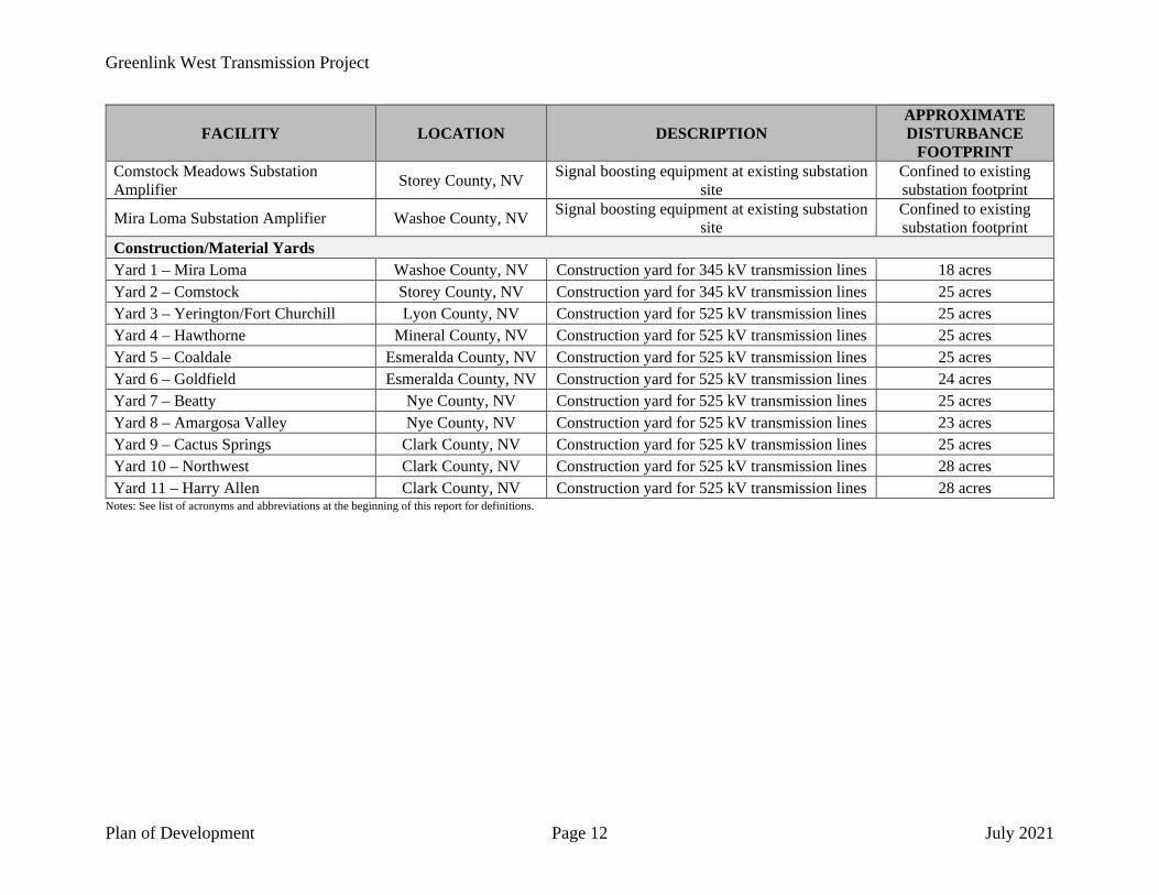
FOOTPRINT Comstock Meadows Substation Amplifier Storey County, NV Signal boosting equipment at existing substation
site Confined to existing substation footprint
Mira Loma Substation Amplifier Washoe County, NV Signal boosting equipment at existing substation site
Confined to existing substation footprint
Construction/Material Yards Yard 1 – Mira Loma Washoe County, NV Construction yard for 345 kV transmission lines 18 acres Yard 2 – Comstock Storey County, NV Construction yard for 345 kV transmission lines 25 acres Yard 3 – Yerington/Fort Churchill Lyon County, NV Construction yard for 525 kV transmission lines 25 acres Yard 4 – Hawthorne Mineral County, NV Construction yard for 525 kV transmission lines 25 acres Yard 5 – Coaldale Esmeralda County, NV Construction yard for 525 kV transmission lines 25 acres Yard 6 – Goldfield Esmeralda County, NV Construction yard for 525 kV transmission lines 24 acres Yard 7 – Beatty Nye County, NV Construction yard for 525 kV transmission lines 25 acres Yard 8 – Amargosa Valley Nye County, NV Construction yard for 525 kV transmission lines 23 acres Yard 9 – Cactus Springs Clark County, NV Construction yard for 525 kV transmission lines 25 acres Yard 10 – Northwest Clark County, NV Construction yard for 525 kV transmission lines 28 acres Yard 11 – Harry Allen Clark County, NV Construction yard for 525 kV transmission lines 28 acres
Notes: See list of acronyms and abbreviations at the beginning of this report for definitions.

Greenlink West Transmission Project
Plan of Development Page 13 July 2021
4.2.1 Transmission Lines
525 kV Fort Churchill-Northwest and Harry Allen-Northwest Lines
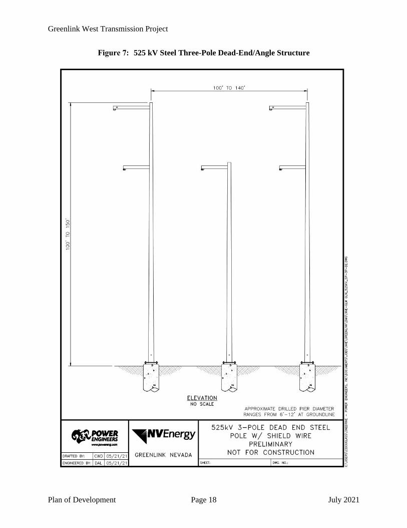
The 525 kV Fort Churchill-Northwest Line and 525 kV Harry Allen-Northwest Line will include the combined placement of approximately 1,809 tangent structures and 192 dead-end and angle structures. Tangent 525 kV structures will consist of steel pole H-Frame, steel monopole (single pole), or guyed steel lattice structures and range between 100 feet and 180 feet tall. Dead-end and angle structures will consist of steel three-pole structures or steel lattice towers and range between 100 feet and 150 feet tall. Typical drawings of 525 kV transmission structures to be installed are provided as Figures 3 through 8.
The 525 kV transmission lines will consist of three phases per circuit, three conductors per phase. Each conductor is 1590 thousand circular mil (“kcmil”) aluminum conductor steel reinforced (“ACSR”) conductor which is 1.504 inches in diameter. The transmission line will also include one extra high strength steel shield wire 0.4375 inch in diameter and one optical ground wire (“OPGW”) fiber optic shield wire, containing between 96 and 144 fibers, for control and operation of the transmission system. The typical distance between structures will be approximately 1,200 feet. The minimum ground clearance for the 525 kV transmission lines will be approximately 35 feet at 212 degrees Fahrenheit maximum operating temperature. The line will meet or exceed the requirements of the National Electric Safety Code.
345 kV Fort Churchill-Comstock Meadows #1 Line
The 345 kV Fort Churchill-Comstock Meadows #1 Line will include the placement of approximately 148 tangent structures and 25 dead-end and angle structures. Tangent 345 kV structures will consist of steel pole H-Frame structures and range between 75 feet and 125 feet tall. Dead-end structures will consist of steel three-pole structures and range between 75 feet and 125 feet tall. Typical drawings of 345 kV transmission structures to be installed are provided as Figures 9 and 10.
The 345 kV transmission line conductor will consist of three phases per circuit, two conductors per phase. Each conductor is 954 kcmil ACSR conductor which is 1.165 inches in diameter. The transmission line will also include one extra high strength steel shield wire 0.375 inch in diameter and one OPGW fiber optic shield wire 0.646 inch in diameter for control and operation of the transmission system. The typical distance between structures will be approximately 1,200 feet. The minimum ground clearance for the 345 kV transmission line will be approximately 28 feet. All of the poles will be electrically grounded through use of ground rods. The line will meet or exceed the requirements of the National Electric Safety Code.

Greenlink West Transmission Project
Plan of Development Page 14 July 2021
525 kV Steel Pole H-Frame Tangent Structure

Greenlink West Transmission Project
Plan of Development Page 15 July 2021
525 kV Steel Monopole Tangent Structure

Greenlink West Transmission Project
Plan of Development Page 16 July 2021
525 kV Steel Monopole Vertical Tangent Structure

Greenlink West Transmission Project
Plan of Development Page 17 July 2021
525 kV Steel Guyed Lattice Tangent Structure
Greenlink West Transmission Project
Plan of Development Page 18 July 2021
525 kV Steel Three-Pole Dead-End/Angle Structure

Greenlink West Transmission Project
Plan of Development Page 19 July 2021
525 kV Self-Supporting Steel Lattice Dead-End/Angle Structure

Greenlink West Transmission Project
Plan of Development Page 20 July 2021
345 kV Steel Pole H-Frame Tangent Structure

Greenlink West Transmission Project
Plan of Development Page 21 July 2021
345 kV Steel Three-Pole Dead-End Structure

Greenlink West Transmission Project
Plan of Development Page 22 July 2021
345 kV Fort Churchill-Comstock Meadows #2 Line
The 345 kV Fort Churchill-Comstock Meadows #2 Line will include the placement of approximately 134 tangent structures and 21 dead-end and angle structures configured similar to the 345 kV Fort Churchill-Comstock Meadows #1 Line.
345 kV Fort Churchill-Mira Loma Line
The 345 kV Fort Churchill-Mira Loma Line will include the placement of approximately 180 tangent structures and 31 dead-end and angle structures configured similar to the Fort Churchill-Comstock Meadows #1 Line.
4.2.2 Substations
Fort Churchill 500/345/230/120 kV Substation
The new Fort Churchill 500/345/230/120 kV Substation will be constructed approximately 1,600 feet west of the existing Fort Churchill 230/120 kV Substation and within an approximately 371-acre area (see Attachment C: Substation Arrangement Drawings). The proposed substation will also require the construction of one new 525 kV getaway, three new 345 kV getaways and realignment of one existing 230 kV transmission line and nine existing 120 kV transmission getaways (see Attachment C: Substation Arrangement Drawings). All substation and transmission line realignment work will be on private land or land owned by NV Energy. The proposed Fort Churchill Substation will contain the following electrical equipment:
• One 525 kV line terminal.
• Two 525/345 kV 600 MVA 3-phase transformers.
• Two 525 kV 75 megavolt ampere (reactive) (“MVAR”) 3-phase shunt reactors.
• One 525 kV 455 MVAR 3-phase series capacitor.
• Two 345/230 kV 300 MVA 3-phase transformers.
• Two 345/120 kV 280 MVA 3-phase transformers.
• Seven sets 525 kV 63 kiloampere (“kA”) single pole breakers.
• Seventeen sets 345 kV 63 kA single pole breakers.
• Four 230 kV 63 kA 3-phase breakers.
• Nineteen 120 kV 63 kA 3-phase breakers.
• Four 120 kV station service voltage transformers.
• Eighty-nine coupling capacitor voltage transformers (“CCVTs”).
• Instrument transformers.
• Six new control enclosures to accommodate new protection panels.

Greenlink West Transmission Project
Plan of Development Page 23 July 2021
• Switches, service transformers, and associated bus work and hardware.
• New telecommunication infrastructure including fiber optic cable and microwave antennae tower for control and operation of the transmission system.
Esmeralda 500/230 kV Substation
The new Esmeralda 500/230 kV Substation will be constructed approximately 32 miles west of Tonopah, Nye County, Nevada and require an area of approximately 71 acres (see Generic Collector Substation Conceptual Layout in Attachment C: Substation Arrangement Drawings). The proposed substation will also require the construction of two transmission line getaways. All substation and transmission line realignment work will be on public land. The proposed Esmeralda Substation will contain the following electrical equipment:
• Two 525 kV line terminals.
• Eight sets 525 kV 63-kA single pole breakers.
• Two 525 kV 50-MVAR 3-phase shunt reactors.
• Two 525 kV 75-MVAR 3-phase shunt reactors.
• Two 525 kV 455-MVAR 3-phase series capacitors.
• Fifteen 525 kV single phase CCVTs.
• Instrument transformers.
• New control enclosure to accommodate new protection panels.
• New telecommunications infrastructure including fiber optic cable for control and operation of the transmission system.
• Switches, service transformers, and associated bus work and hardware.
• Backup generator.
Amargosa 500/230 kV Substation
The new Amargosa 500/230 kV Substation will be constructed approximately 24 miles southeast of Beatty, Nye County, Nevada and require an area of approximately 71 acres (see Generic Collector Substation Conceptual Layout in Attachment C: Substation Arrangement Drawings). The proposed substation will also require the construction of two transmission line getaways. All substation and transmission line realignment work will be on public land. The proposed Amargosa Substation will contain the following electrical equipment:
• Two 525 kV line terminals.
• Eight sets 525 kV 63-kA single pole breakers.
• Two 525 kV 50-MVAR 3-phase shunt reactors.
• Two 525 kV 75-MVAR 3-phase shunt reactors.
Greenlink West Transmission Project
Plan of Development Page 24 July 2021
• Two 525 kV 455-MVAR 3-phase series capacitor.
• Fifteen 525 kV single phase CCVTs.
• Instrument transformers.
• New control enclosure to accommodate new protection panels.
• New telecommunications infrastructure including fiber optic cable for control and operation of the transmission system.
• Switches, service transformers, and associated bus work and hardware.
• Backup generator.
Northwest 500/230 kV Substation
The existing Northwest 500/230 kV Substation will be expanded to the west of the existing substation and require an additional area of approximately 17 acres (see Attachment C: Substation Arrangement Drawings). The proposed expansion will also require the construction of two transmission line getaways. Substation expansion and transmission line realignment work will be on both public land and private property. Expansion of the Northwest Substation will include installation of the following new electrical equipment:
• Two 525 kV line terminals.
• Six sets 525 kV 63-kA single pole breakers.
• Two 525 kV 75-MVAR 3-phase shunt reactors.
• One 525 kV 455-MVAR 3-phase series capacitor.
• Three 525 kV single phase CCVTs.
• Instrument transformers.
• New telecommunications infrastructure including fiber optic cable for control and operation of the transmission system.
• Switches, service transformers, and associated bus work and hardware.
Harry Allen 500 kV Substation
Line terminal equipment will be installed at the existing Harry Allen 500 kV Substation (see Attachment C: Substation Arrangement Drawings). All substation and transmission line work will occur within the existing substation boundaries (i.e., the extents of the station footprint will not change). Line terminal equipment at the Harry Allen Substation will include installation of the following new electrical equipment:
• One 525 kV line terminal.
• Three sets 525 kV 63-kA single pole breakers.
• Three 525 kV single phase CCVTs.

Greenlink West Transmission Project
Plan of Development Page 25 July 2021
• Instrument transformers.
• Switches, service transformers, and associated bus work and hardware.
Comstock Meadows 345/120 kV Substation
Line terminal equipment will be installed at the existing Comstock Meadows 345/120 kV Substation (see Attachment C: Substation Arrangement Drawings). All substation and transmission line work will occur within the existing substation boundaries (i.e., the extents of the station footprint will not change). Line terminal equipment at the Comstock Meadows Substation will include installation of the following new electrical equipment:
• Two 345 kV line terminals.
• Six 345 kV 40-kA 3-phase breakers.
• Instrument transformers.
• Switches, service transformers, and associated bus work and hardware.
• New telecommunication infrastructure including fiber optic cable for control and operation of the transmission system.
Mira Loma 345/120 kV Substation
Line terminal equipment will be installed at the existing Mira Loma 345/120 kV Substation (see Attachment C: Substation Arrangement Drawings). All substation and transmission line work will occur within the existing substation boundaries (i.e., the extents of the station footprint will not change). Line terminal equipment at the Mira Loma Substation will include installation of the following new electrical equipment:
• One 345 kV line terminal.
• Three 345 kV 40-kA 3-phase breakers.
• Instrument transformers.
• Switches, service transformers, and associated bus work and hardware.
• New telecommunication infrastructure including fiber optic cable for control and operation of the transmission system.
4.2.3 Telecommunications
As previously described, NV Energy will install OPGW as a component of the 525 kV and 345 kV transmission lines for control and operation of the transmission system. The OPGW will be over-sized to accommodate potential future broadband service. To provide secure and reliable communications for the control system real-time requirements, protection, and day-to-day operations and maintenance needs, a mix of telecommunications systems will be used.

Greenlink West Transmission Project
Plan of Development Page 26 July 2021
Microwave Radio Facilities
In addition to OPGW, NV Energy will construct new microwave radio facilities to provide a diverse and redundant telecommunications path pursuant to North American Electric Reliability Corporation reliability standards. Microwave equipment will be located within new substations, at existing microwave radio facility locations, or at new greenfield locations. Proposed upgrades to existing facilities will be constructed within the existing microwave facility footprints, while new greenfield facilities will be constructed adjacent to existing facilities. The proposed microwave radio facilities are summarized in Table 3 and depicted on the maps in Attachment B.
Microwave Radio Facilities
SITE LATITUDE LONGITUDE SCOPE1 AREA (ACRES)2
Fort Churchill Substation 39.131083 -119.141488 Substation 0.0 TV Hill 38.457670 -118.765700 Existing 0.0 Pilot Peak 38.342797 -117.973600 New 0.9 Esmeralda Substation 38.009710 -117.808260 Substation 0.0 Montezuma 37.700881 -117.383600 New 0.9 Gold Mountain 37.299686 -117.261300 New 0.9 Sawtooth 36.934389 -116.851400 New 0.9 Amargosa Substation 36.657176 -116.510487 Substation 0.0 Amargosa 36.414093 -116.420430 New 2.3 Spotted Range 36.632647 -115.977300 New 0.9 Angel Peak 36.318810 -115.575196 Existing 0.1
Total - - - 7.0 Notes: 1 Proposed “Existing” microwave facilities will be constructed within existing radio facility footprints. Proposed “New” microwave facilities will be constructed next to existing radio facilities. Facilities to be installed at greenfield substations will be constructed within the substation boundaries; no additional disturbance will be needed. 2 Numbers have been rounded for presentation purposes. As such, totals may not reflect the sum of the addends.
The proposed microwave radio facilities will also require electric distribution service and installation of a backup generator.
Optical Amplifier Sites
The optical data signal degrades with distance as it travels through the optical fiber cable and will require the installation of signal boosting equipment within existing or proposed substation sites (amplifier sites) as well as greenfield signal regeneration sites, which will be located within the transmission line ROW. For simplicity, both types of sites are referred to as amplifier sites hereafter. The proposed amplifier sites are summarized in Table 4 and depicted on the maps in Attachment B.

Greenlink West Transmission Project
Plan of Development Page 27 July 2021
Amplifier Sites
SITE LATITUDE LONGITUDE SCOPE AREA (ACRES)1
Fort Churchill Substation Amplifier 39.130158 -119.141571 Substation 0.0 Amplifier Site 4 38.617679 -118.549541 Greenfield 0.9 Esmeralda Substation Amplifier 38.011207 -117.806652 Substation 0.0 Amplifier Site 3 37.784401 -117.437267 Greenfield 0.9 Amplifier Site 2 37.137912 -116.856807 Greenfield 0.9 Amargosa Substation Amplifier 36.721658 -116.622281 Substation 0.0 Amplifier Site 1 36.562193 -116.123204 Greenfield 0.9 Northwest Substation Amplifier 36.334624 -115.330804 Substation 0.0 Comstock Meadows Substation Amplifier 39.495103 -119.438021 Substation 0.0
Mira Loma Substation Amplifier 39.455636 -119.717495 Substation 0.0 Total - - - 3.7
Notes: 1 Numbers have been rounded for presentation purposes. As such, totals may not reflect the sum of the addends.
The proposed amplifier sites will also require electric distribution service and installation of a backup generator. NV Energy will optimize the location of optical amplifier sites to minimize the length and impact of distribution electric service.
4.3 LAND/RIGHT-OF-WAY REQUIREMENTS
4.3.1 Temporary (Construction)
In order to accommodate construction activities, NV Energy will require a 600-foot-wide temporary ROW (1,200 feet in areas with steep terrain) for the proposed 525 kV and 345 kV transmission lines. Temporary construction work area requirements are described below and summarized in Table 5. For simplicity, state and federally administered lands are categorized as public hereafter, and tribal and local lands are categorized as private.
Temporary Disturbance Areas
WORKSPACE AREA REQUIRED
TOTAL APPROXIMATE ACREAGE OF TEMPORARY
DISTURBANCE1 Private Public
Transmission Lines
525 kV Structure Work Areas
1,809 sites x 200 feet x 250 feet (tangent structures) 115 1,961
192 sites x 200 feet x 400 feet (dead-end/angle structures) 20 333
17 sites x 200 feet x 100 feet (guard structures) <1 7

Greenlink West Transmission Project
Plan of Development Page 28 July 2021
WORKSPACE AREA REQUIRED
TOTAL APPROXIMATE ACREAGE OF TEMPORARY
DISTURBANCE1 Private Public
345 kV Structure Work Areas
462 sites x 160 feet x 250 feet (tangent structures) 259 165
77 sites x 160 feet x 400 feet (dead-end structures) 69 44
6 sites x 160 feet x 100 feet (guard structures) 1 1
Pull Sites 401 sites x variable acres 1,189 3,366 Construction Yards 11 sites x variable acres 242 30 Access Access Roads See Section 4.3.2 - - Service Roads See Section 4.3.2 - -
Total 1,896 5,908 Notes: 1 Numbers have been rounded for presentation purposes. As such, totals may not reflect the sum of the addends.
Transmission Structure Work Areas
In order to accommodate construction equipment and activities, temporary work pads will be needed for each structure and will be sized based on the structure type. For the proposed 525 kV transmission lines, work pads for each tangent structure will measure 200 feet by 250 feet, 200 feet by 400 feet for each dead-end/angle structure, and 200 feet by 100 feet for each temporary guard structure. For the proposed 345 kV transmission lines, work pads for each tangent structure will measure 160 feet by 250 feet, 160 feet by 400 feet for each dead-end/angle structure, and 160 feet by 100 feet for each temporary guard structure. As summarized in Table 5, the transmission structure work areas will disturb a total area of approximately 465 acres on private land and 2,512 acres on public land.
Pull Sites
Approximately 401 wire pulling and tensioning sites (hereafter referred to as pull sites) will be necessary for installation of the conductor, shield wire, and OPGW. Work areas for mid-span pull sites will measure 200 feet by 600 feet for the proposed 525 kV transmission lines and 160 feet by 600 feet for the proposed 345 kV transmission lines. Pull sites at points of intersection and dead-ends will require a 700-foot radial work area centered on the structure. As summarized in Table 5, pull sites will temporarily disturb a total area of approximately 1,189 acres on private land and 3,366 acres on public land.
Construction Yards
Other construction yards including staging areas, concrete batch plants and material yards will be necessary for construction logistics. Eleven construction/materials yards between 18 and 28 acres each have been identified approximately every 50 miles along the transmission line. As

Greenlink West Transmission Project
Plan of Development Page 29 July 2021
summarized in Table 5, construction/material yards will temporarily disturb a total area of approximately 242 acres on private land and 30 acres on public land.
Fly yards and refueling sites will also be needed for helicopter transport of structures, personnel, and materials. Refueling sites measuring 250 feet by 160 feet will be needed approximately every three to five miles along the transmission line route for structure transport helicopters. Refueling sites measuring 100 feet by 100 feet will be needed approximately every three miles. Fly yard and helicopter refueling locations have not yet been identified.
Access
A combination of new and existing access roads will be needed for Project construction and operation as described below. Following construction, new and improved access roads will be maintained as permanent. As such, the associated disturbance impacts are included in the permanent impacts summary table in Section 4.3.2. Preliminary access roads are depicted on the maps in Attachment B.
Existing Access Roads
Access for Project construction will be achieved primarily via existing roads. In some cases, existing improved and unimproved dirt roads will require widening or other improvements to accommodate construction equipment. Three types of existing access roads will be used for access as described below. Access roads and proposed improvements will be discussed in more detail in the construction, operation, and maintenance plan (“COM Plan”) once the roads have been field-verified and an agency preferred alternative is selected.
• Paved roads: Paved roads are expected to be accessible under any conditions by all construction equipment and are not expected to require either maintenance or improvement.
• Unpaved (dirt/gravel) roads that do not require improvements: These roads are graded roads (some segment of which may be graveled) that are used relatively frequently and should be accessible under most weather conditions. These roads will not need improvement for construction access, but they will be maintained as required (typically light grading) to keep the road in acceptable condition for both construction use and for other users. Such maintenance activity will not increase the currently existing profile of the road nor increase surface disturbance.
• Unpaved roads that may require improvements: These include minimally improved and unimproved dirt roads and two-track roads that will need improvements to safely accommodate construction equipment. Normal running width on the access roads requiring improvement will be approximately 25 feet. A 100-foot-wide environmental survey corridor will be established for all roads requiring improvement. Improvements that will be required on these roads include vegetation removal, curve widening, roadbed widening, surface improvement by blading and pushing rocks to either side, and installation of natural drainage crossings, water bars, and other erosion protection measures.

Greenlink West Transmission Project
Plan of Development Page 30 July 2021
In addition, a 75-foot-wide turning radius will be added at roadway intersections and turnout locations as necessary to accommodate oversized equipment and vehicles. These locations will be identified in the COM Plan once the roads have been field-verified.
New Access Roads
NV Energy will construct new access roads from existing access roads and/or between adjacent structure sites to access structure sites for the proposed transmission line in areas of flat terrain and low vegetation. The new access roads will be graded to accommodate all equipment necessary to construct the structure foundations and structures and conduct stringing, including tracked and rubber-tired vehicles.
In areas where vegetation removal is necessary, vegetation will be trimmed by hydro-axing (a lawnmower-type machine) to about 3 to 6 inches above grade, leaving the stems and root systems intact to allow for regrowth. In the event roads become impassible it may become necessary to bring in fill or gravel. The new access roads will be an average width of 25 feet in most areas. Most construction work will be conducted within the 600-foot survey corridor (1,200 feet in areas with steep terrain).
Additional impacts associated with the addition of a 75-foot-wide turning radius at road intersections and turnouts will be identified in the COM Plan once the roads have been field-verified.
Service Roads
In addition to access roads to the new ROW, a service road will also be required along the entire length of the transmission line for operation, maintenance, and patrol activities. An approximately 582-mile-long service road will be needed for the 525 kV transmission lines. The 345 kV transmission lines will require a total of approximately 201 miles of service roads. The service roads will be an average width of 25 feet in most areas.
Service roads will be discussed in more detail in the COM Plan once an agency preferred alternative is selected.
4.3.2 Permanent (Operations and Maintenance)
After Project construction has been completed, NV Energy will require a permanent 200-foot-wide ROW for the 525 kV transmission lines and 160-foot-wide ROW for the 345 kV transmission lines in order to conduct operations and maintenance activities. The transmission lines will be centered within the proposed ROW. Other permanent disturbance areas required are described below and summarized in Table 6. For simplicity, state and federally administered lands are categorized as public hereafter, and tribal and local lands are categorized as private.

Greenlink West Transmission Project
Plan of Development Page 31 July 2021
Permanent Disturbance Areas
WORKSPACE AREA REQUIRED
TOTAL APPROXIMATE ACREAGE OF PERMANENT
DISTURBANCE1 Private Public
Transmission Lines
525 kV Structure Pads
1,155 sites x 100 feet x 100 feet (tangent structures) 15 250
120 sites x 100 feet x 100 feet (dead-end/angle structure) 2 26
525 kV Structure Pads in Desert Tortoise Habitat 726 sites x 200 feet x 200 feet 37 630
345 kV Structure Pads
462 sites x 100 feet x 100 feet (tangent structures) 6 100
77 sites x 100 feet x 100 feet (dead-end structures) 1 17
Substations Fort Churchill Substation (expansion area) 371 acres 371 0
Esmeralda Substation 71 acres 0 71 Amargosa Substation 71 acres 0 71 Northwest Substation (expansion area only) 17 acres 7 10
Harry Allen Substation No new disturbance 0 0 Mira Loma Substation No new disturbance 0 0 Comstock Meadows Substation No new disturbance 0 0
Telecommunications Microwave Sites 7 sites x variable acres 3 4 Optical Amplifier Sites 4 sites x 200 feet x 200 feet 0 4 Access
Access Roads2 157 linear miles private 393 linear miles public
x 25 feet wide3 476 1,190
Service Roads 155 linear miles private 628 linear miles public
x 25 feet wide4 470 1,903
Total 1,386 4,276 Notes:
1 Numbers have been rounded for presentation purposes. As such, totals may not reflect the sum of the addends. 2 Includes only new and existing unpaved roads that may require improvements. 3 Access road width is approximate. 4 Estimated based on the length, grade, and landownership along the transmission centerline length. Multipliers were applied to the straight-line length to account for changes in grade.

Greenlink West Transmission Project
Plan of Development Page 32 July 2021
Transmission Structure Foundations
The permanent disturbance associated with the installed 525 kV and 345 kV transmission line structures will be a function of the structure location. In desert tortoise habitat, permanent structure pads will measure 200 feet by 200 feet. Outside of desert tortoise habitat, permanent structure pads will measure 100 feet by 100 feet. As summarized in Table 6, the transmission structure footprints will disturb a total area of approximately 60 acres on private land and 1,023 acres on public land.
Substations
Expansion of the existing Harry Allen , Mira Loma, and Comstock Meadows Substations will not require any additional disturbance outside the existing substation footprints. Expansion of the existing Northwest Substation and construction of the new Fort Churchill, Amargosa, and Esmeralda Substations will require approximately 378 acres on private land and 152 acres on public land, as summarized in Table 6. Approximately five miles of new or rebuilt distribution line will also be needed to provide electrical service to the new Amargosa and Esmeralda Substations.
Telecommunications
New microwave and amplifier facility footprints will typically measure 200 feet by 200 feet. Electrical service to microwave and amplifier facilities will also require approximately 22 miles and 24 miles of new or rebuilt distribution line, respectively.
Access
As noted, in Section 4.3.1, all new and improved access roads and service roads will be maintained as permanent. As summarized in Table 6, new and existing unpaved access roads that may require improvements will disturb a total area of approximately 476 acres on private land and 1,190 acres on public land; and the proposed service roads will disturb a total area of approximately 470 acres on private land and 1,903 acres on public land.
4.4 CONSTRUCTION ACTIVITIES
4.4.1 Transmission Line
Construction of the transmission line structures and installation of the conductor will occur as follows:
Step 1 – Mobilization and Staging
A crew of 25 to 50 workers will mobilize to the site approximately one week prior to the start of work. During this time, they will transport equipment and construction materials to designated construction staging areas.

Greenlink West Transmission Project
Plan of Development Page 33 July 2021
Step 2 – Preconstruction Surveying and Staking
The initial activity prior to construction is the engineering survey and staking of Project facilities. This may include surveying and marking ROW limits, structure locations, anchor sites, distribution lines, staging and material yards, pull sites, and access roads. In addition, signs, flags, and/or fencing will be used to delineate Project features, such as access, work areas, and sensitive resource areas.
Once the Project area is staked, pre-construction plant and wildlife surveys will occur if required prior to beginning ground clearing. Additional staking may be required just prior to construction to refresh previously installed stakes and flagging and/or delineate any sensitive resource areas identified during the pre-construction field surveys.
Step 3 – Access Road Construction
Construction personnel will use numerous existing access roads to transport materials and equipment to and from the transmission and distribution line corridors, substations, telecommunication sites, and staging areas. The following types of access roads will be used during construction:
1. Existing paved roads. 2. Existing unpaved roads that do not require improvements. 3. Existing unpaved roads that may require improvements (e.g., widening, blading, or
importation of materials to accommodate construction equipment). 4. New access roads.
The Project would utilize existing access roads wherever practical; however, creation of new roads and upgrading existing roads may be required to ensure that equipment is able to access the ROW and delivery vehicles are able to access the laydown areas and structure sites. Upon completion of construction, those access roads that are not necessary for the operation and maintenance of the transmission lines would be restored to pre-construction conditions.
Permanent access roads utilized during construction, operation and maintenance would be graded to a maximum width of 25 feet. Roads may need to be widened at some locations to allow for curve widening, cut-and-fill on side slopes, side casting, or other surface improvements. Other areas along existing access roads may be cut and filled to provide the proper grade for equipment access and wire setup sites at some of the angle points. Spur roads off of the main access roads would be constructed to structure pad sites, as necessary. Many of these spur roads would also be permanent, as they would provide access to the pad sites during operation and maintenance activities. New access roads and spur roads would require a certain degree of flexibility in their routing and construction as they would be subject to meandering to avoid difficult terrain and potentially sensitive habitat or species. In areas of rough terrain, new access roads created along steep slopes would most likely exceed the average 25-foot width. The width needed for these “side-hill roads” would vary and would be determined based upon the engineering and safety constraints. The width of these types of access roads would be determined during the engineering phase of the Project.

Greenlink West Transmission Project
Plan of Development Page 34 July 2021
Access roads and spur roads would be cleared primarily by a mower or hydro-axe but may also include blading, tree removal, and bridge/culvert construction. As much as possible, clearing would be performed in a manner that leaves the root systems intact in order to encourage regrowth and minimize erosion. In rough terrain, side slopes would be cut and filled using grading equipment, and rocks or other obstructions would be bladed to allow for passage of rubber-tired vehicles. If rocks cannot be removed with heavy equipment, they may need to be blasted with explosives. Temporary work areas, spur roads, and access roads that are not necessary for the operation and maintenance of the transmission lines would be reclaimed and reseeded after construction.
Where possible, drainages would be crossed at grade. In areas where this type of crossing is not feasible, appropriate drainage facilities (e.g., culverts, wing ditches) would be designed and constructed and the appropriate permits would be obtained.
Specific actions would be implemented to reduce the impacts of the construction of the access roads. Measures to mitigate impacts, such as the installation of water bars and dips to control erosion would be included. In addition, measures would be taken to minimize impacts in specific locations and during certain periods of the year. Areas considered sensitive could be avoided altogether and the use of the roads during heavy rains or high wind events could be limited to help mitigate impacts during construction. Access road needs would be determined after design and engineering requirements are finalized.
Step 4 – Right-of-Way Preparation
In order to establish sufficiently sized work areas, pull sites, and staging areas, some vegetation clearing and grading will be conducted. In all temporary work locations, vegetation removal will be minimized to the extent possible. Because the structure sites and the structure stringing sites require a fairly flat surface, the areas may be graded and soil may be imported to achieve the necessary elevation.
Step 5 – Structure Installation
Holes for structures will be excavated using augers or other back-hoe type equipment. Holes for 345 kV structures will be four to eight feet in diameter and 20 to 40 feet deep. Holes for 525 kV tangent structures will be approximately six to 12 feet in diameter and 15 to 30 feet deep. Holes for 525 kV dead-end structures will be approximately four to five feet in diameter and 20 to 40 feet deep. Dimensions will vary subject to structure loading and soil conditions. Additionally, holes for guy wire anchors will be excavated as necessary. Blasting may be required in rocky areas where normal excavation methods are unable to meet Project excavation specifications.
Dead-end and angle structure pier foundations would be constructed of cast-in-place, steel reinforced concrete. Excavation for foundations would be made with track or truck-mounted augers capable of excavating the proper size hole. Should rocky areas be encountered, foundation holes may be excavated by rock drills. Foundation holes would be covered during construction to protect the public and wildlife while left unattended (e.g., overnight, weekends, holidays, weather delays). If practical, temporary fencing would be used. Prior to commencing drilling, the first six inches of topsoil would be removed and stockpiled for use in the restoration process. Soil removed

Greenlink West Transmission Project
Plan of Development Page 35 July 2021
from foundation holes during the drilling process would be stockpiled in the work area and segregated from the topsoil. This stockpiled soil would be spread evenly on the ROW or used to backfill holes.
Materials, including structure materials, insulators, hardware, and guy wire anchors, will be delivered to the Project site via flatbed truck and will be assembled on site using a crane or other heavy construction equipment. The assembled transmission structures will be placed into the excavated holes or set on pre-cast concrete foundations using a large mobile crane or helicopter. Direct bury pole bases will be buried in the ground, and native soil will be used to fill the holes (imported soil will be used if native material is unsuitable for compaction). At three-pole and guyed-V lattice structures, guy wires to support the structures may be used to plumb and support the structures. Crews will attach insulators, travelers, and hardware to the cross arm either prior to or after structure erection depending on access.
Step 6 – Conductor Installation
As mentioned previously, the conductor will consist of three phase, three sub-conductor bundled 1590 kcmil ACSR or two sub-conductor bundled 954 kcmil ACSR. The conductor will be installed onto new transmission structures by a sock line (a small cable used to pull conductor) attached to the other end of the new conductor and pulled into the travelers using the pulling equipment staged at the pulling sites or by helicopters.
Once the conductor is pulled into place, conductor tensions between the structures will be adjusted to a pre-calculated level. The line will be installed with a minimum ground clearance of 35 feet for the 525 kV transmission lines and 28 feet for 345 kV construction. The new conductor will then be clipped into the end of each insulator on each structure, the travelers will be removed, spacer/dampers, vibration dampers, and other hardware will be installed. Shield wire installation will be accomplished in a similar manner.
Step 7 – Site Cleanup and Demobilization
Surplus materials, equipment, and construction debris will be removed at the completion of construction activities. All man-made construction debris will be removed and disposed of as appropriate at permitted landfill sites. Cleared vegetation will either be shredded and spread over the ROW as mulch and erosion control or disposed of off-site, depending on agency agreements. Rocks removed during access road grading and foundation excavation will be redistributed over the ROW to match adjacent site conditions.
Step 8 – Restoration and Reclamation
Once construction has been completed, existing and permanent access roads will remain improved. Designated temporary work areas and spur roads may be reclaimed as stipulated to pre-construction conditions. Areas within the ROW disturbed by construction activities will be recontoured, decompacted, and seeded. Seed mixes approved by the BLM or other land managing agencies (as applicable) will be applied to these disturbed areas. NV Energy will attempt to close or restrict vehicle access to areas that have been seeded until the reclamation success criteria have been satisfied.

Greenlink West Transmission Project
Plan of Development Page 36 July 2021
4.4.2 Substations
Expansion of the existing Northwest Substation and construction of the new Amargosa, Esmeralda, and Fort Churchill Substations will occur as follows:
Step 1 – Preconstruction Surveying and Staking
Preconstruction surveying and staking activities at the substation sites will be similar to those described for transmission line construction.
Step 2 – Site Preparation
Work at the proposed substation sites will begin by clearing existing vegetation and grading level pads for installation of the stations.
Step 3 – Fencing
Once the pads are prepared, the sites will be secured with chain-link fencing. Holes for the structure footings and underground utilities will then be excavated; the footings and underground utilities will be installed, including electrical conduits and additions to the ground grid; and the excavations will be backfilled. Aboveground structures and equipment will then be installed.
Step 4 – Graveling
Once the equipment is installed, medium gray gravel, two inches wide or less, will be spread over the sites to a depth of approximately four inches.
Step 5 – Site Cleanup and Demobilization
Substation site cleanup and demobilization activities will be similar to those described for transmission line construction.
Line terminal equipment installation activities at the existing Harry Allen, Comstock Meadows, and Mira Loma Substations will not require a change in the substation footprints. At these locations, some or all of the steps identified above may not be necessary.
4.4.3 Telecommunications Facilities
Telecommunications facilities will be constructed concurrently with the transmission lines and substations. For new microwave radio and optical amplifier sites, construction will occur as follows:
Step 1 – Preconstruction Surveying and Staking
Preconstruction surveying and staking activities at the telecommunications sites will be similar to those described for transmission line construction.

Greenlink West Transmission Project
Plan of Development Page 37 July 2021
Step 2 – Site Preparation
Site development work will include clearing, grubbing, grading, and construction of an all-weather access road (gravel) as required.
Clearing of all vegetation will be required for the entire site, including a distance of approximately 50 feet outside the fence to provide for a firebreak. Once the vegetation is cleared, the entire site will be graded to a nearly level work area with enough slope to provide for runoff of precipitation. After grading, the entire site will be treated with a soil sterilizer to prevent vegetation growth to minimize future maintenance. A thin layer of gravel or crushed rock will then be applied to the finished surface of the site.
Step 3 – Fencing
Security fencing measuring seven feet in height will be installed around the perimeter of each site. The fence will be constructed of chain link with steel posts and include a one-foot barbed wire (or similar material) along the top of the chain link for a total fence height of eight feet. A locked gate will be installed for authorized vehicle and personnel access.
Step 4 – Foundation and Structure Installation
Foundations for the prefabricated building(s), generators, and fuel storage tanks, as required, will be slab-on-grade type. These foundations will be placed by excavating the foundation area; placing forms, reinforced steel, and anchor bolts; and then placing concrete into the forms. After the foundations have been poured, the forms are removed, and the surface of the foundation finished. Reinforced steel and anchor bolts will be transported to each site by truck, which will then be fabricated into cages or mats on the site. Concrete will be hauled to the site in concrete trucks. Prefabricated building(s), generators, and fuel storage tanks, as required, will be transported to the site by truck and attached to the foundations by means of threaded anchor bolts embedded in the concrete.
Microwave structures may include lattice or tubular structures up to 200 feet in elevation. These structures will be transported to the site by truck and assembled and erected on site. Microwave structures will be placed adjacent to existing facilities or will supplement existing infrastructure already installed. These structures will require drilled foundations including poured concrete, reinforced steel, and anchor bolts. Existing access roads and distribution power services will be used to service these sites.
At the amplifier sites, the fiber optic cable will be connected from the splice box located near the bottom of the nearest transmission structure to the control building at the amplifier site via two diverse paths, either overhead or underground. The overhead path may require one or more short distribution type poles located within the transmission line ROW. An underground path will require trenching and burial of an underground fiber optic cable. All trenching would occur within the transmission line ROW. Connection to a local electric distribution circuit will be required to provide power to the optical amplifier sites.

Greenlink West Transmission Project
Plan of Development Page 38 July 2021
Step 5 – Site Cleanup and Demobilization
Site cleanup and demobilization activities will be similar to those described for transmission line construction.
4.4.4 Personnel
During peak construction periods it is anticipated that as many as 250 personnel will be deployed including construction and support personnel, inspectors, surveyors, Project managers, and environmental inspectors.
4.4.5 Equipment
Table 7 presents a list of the typical equipment and their uses for construction of this type of project.
Typical Construction Equipment
EQUIPMENT USE ¾-ton and 1-ton pickup trucks Transport construction personnel 2-ton flatbed trucks; flatbed boom truck Haul and unload materials Rigging truck Haul tools and equipment Mechanic truck Service and repair equipment Aerial bucket trucks Access poles, string conductor, and other uses Shop vans Store tools Bulldozer Grade access roads and pole sites and reclamation Road grader Construct, maintain, and upgrade roads Compactor Construct access roads Truck mounted digger or backhoe Excavate Small mobile cranes (12 tons) Load and unload materials Large mobile cranes (75 tons) Erect structures Transport Haul poles and equipment Drill rig with augers Excavate and install fences Puller and tensioner Pull conductor and wire Cable reel trainers Transport cable reels and feed cables into conduit Semi tractor-trailers Haul structures and equipment Splice trailer Store splicing supplies and air condition manholes Take-up trailers Install conductor Air compressors Operate air tools Air tampers Compact soil around structure foundations Dump truck Haul excavated materials and import backfill Fuel and equipment fluid truck Refuel and maintain vehicles Water truck Suppress dust and fire

Greenlink West Transmission Project
Plan of Development Page 39 July 2021
EQUIPMENT USE Winch truck Install and pull sock line and conductors into position
Helicopter Transport equipment and personnel, erect structures, pull conductor sock-line and hard-line
4.4.6 Schedule
NV Energy has a planned in-service date of December 2026. The Project will take approximately three years to complete.
4.5 OPERATIONS AND MAINTENANCE ACTIVITIES
Once the new facilities are operational, NV Energy operations and maintenance personnel will conduct annual inspections of the lines and substations. Annual inspections will be conducted by helicopter, all-terrain vehicles, or line trucks. The inspections will include visual review of the line along the access roads.
Approximately every 10 years, NV Energy personnel will conduct structure-climbing inspections. These inspections consist of accessing the structure using four-wheel drive vehicles on existing access roads and service roads. NV Energy personnel will then climb structures to inspect the hardware, condition of the structures, and insulators.
Aside from annual inspections, NV Energy personnel will also need to access the line in the event maintenance of a structure is required or under emergency conditions. Under these circumstances, the line would be accessed by line trucks using existing access roads or by helicopter.
4.6 REQUIRED AUTHORIZATIONS
Table 8 provides a list of the potential permits, licenses, approvals, and other authorizations needed to construct and operate the Project.

Greenlink West Transmission Project
Plan of Development Page 40 July 2021
Potentially Required Permits and Authorizations
ISSUE ACTION REQUIRING PERMIT, APPROVAL,
OR REVIEW AGENCY PERMIT, LICENSE,
OR REVIEW RELEVANT LAWS AND
REGULATIONS
Federal
NEPA Compliance
Federal action: to grant ROW across land under federal jurisdiction
Lead agencies; Affected land-managing agencies; Cooperating agencies
EIS and Records of Decision
NEPA (42 U.S.C. § 4321); Council on Environmental Quality (40 C.F.R. 1500-1508); Department of Energy NEPA implementing Regulations (10 C.F.R. 1021)
ROW Across Land Under Federal Management
Pre-construction surveys, construction, operation, maintenance, and abandonment
BLM ROW Grant FLPMA of 1976 (PL 94-579); 43 U.S.C. §§1761-1771; 43 C.F.R. 2800
BLM Short-Term ROW Grant FLPMA (PL 94-579); 43 U.S.C. §§1761-1771; 43 C.F.R. 2800
BLM Resource Management Plans BLM requirements
BLM POD / COM Plan BLM requirements
BLM Notice to Proceed 43 C.F.R. 2800, Subpart 2807 – Grant Administration and Operation, Section 2807.10 concerning Notice to Proceed
BLM Pesticide Use Proposal Final Vegetation Treatments Using Herbicides Programmatic EIS (BLM 2007)
BIA, tribe ROW grant across American Indian lands 25 C.F.R. 169
USFS Special Use Authorization and temporary use permit
National Forest Management Act of 1976, 16 U.S.C. §1600, et seq.; 16 U.S.C. § 1604(e), 1607 and 1609
USFS Short-Term Special Use Authorization
National Forest Management Act of 1976, 16 U.S.C. §1600, et seq.; 16 U.S.C. § 1604(e), 1607 and 1609
USFS Land and Resource Management Plans USFS requirements
USFS POD / COM Plan USFS requirements

Greenlink West Transmission Project
Plan of Development Page 41 July 2021
ISSUE ACTION REQUIRING PERMIT, APPROVAL,
OR REVIEW AGENCY PERMIT, LICENSE,
OR REVIEW RELEVANT LAWS AND
REGULATIONS
USFS Notice to Proceed 43 C.F.R. 2800, Subpart 2807 – Grant Administration and Operation, Section 2807.10 concerning Notice to Proceed
DoD Easements for ROWs 10 U.S.C. § 2668(a) Construction, operation, maintenance, and abandonment of transmission line across or within highway ROWs
Federal Highway Administration
Permits to cross Federal Aid Highway; 4 (f) compliance
United States Department of Transportation Act, 23 C.F.R. 1.23 and 1.27; 23 U.S.C. §§ 109 and 315; 23 C.F.R. 645; 23 C.F.R. 771
Biological Resources
Grant ROW by federal land- managing agency USFWS
Endangered Species Act compliance by federal land-managing agency and lead agency
Endangered Species Act of 1973 as amended (16 U.S.C. § 1531 et seq.)
Ground Disturbance and Water Quality Degradation
Construction activities that disturb one or more acres of land
USEPA
Section 402 NPDES General Permit and accompanying Notice of Intent and Stormwater Pollution Prevention Plan for Stormwater Discharges from Construction Activities
Clean Water Act (33 U.S.C. §1342)
Construction across water resources USACE General easement 10 U.S.C. §§ 2668 to 2669
Potential discharge into waters of the state (including wetlands and washes)
USACE (and states); USEPA on tribal lands
Section 401 Water Quality Certification Clean Water Act (33 U.S.C. §1344)
Discharge of dredged or fill material into waters of the United States, including wetlands
USACE; USEPA on tribal lands
Section 404 Permit, Individual or Nationwide Permit
Clean Water Act (33 U.S.C. §1344)
Potential pollutant discharge during construction, operation, and maintenance
USEPA Spill Prevention, Control, and Countermeasure Plan for oil- filled equipment
Oil Pollution Act of 1990 (40 C.F.R. 112)

Greenlink West Transmission Project
Plan of Development Page 42 July 2021
ISSUE ACTION REQUIRING PERMIT, APPROVAL,
OR REVIEW AGENCY PERMIT, LICENSE,
OR REVIEW RELEVANT LAWS AND
REGULATIONS
Cultural Resources
Disturbance of historic properties
Federal lead agency, SHPO, Advisory Council on Historic Preservation
Section 106 consultation and signed Programmatic Agreement prior to Record of Decision
National Historic Preservation Act of 1966, (16 U.S.C. § 470) (36 C.F.R. 800)
Air Traffic Location of towers in regard to airport facilities and airspace
Federal Aviation Administration
A “Determination of No Hazard to Air Navigation” for structure heights and locations in proximity to public airports
Federal Aviation Act of 1958 (PL 85-726) . (14 C.F.R. 77)
Section 1101 Air Space Permit for air space construction clearance
Federal Aviation Act of 1958 (PL 85-726). (14 C.F.R. 77)
Tribal Walker River and Las Vegas Paiute
ROW Encroachment
Encroachment onto Indian Reservation Land
Walker River and Paiute Indian Tribes-BIA Department of Energy and Minerals
ROW easement 25 C.F.R. 169
State
ROW Encroachment
Encroachment into state roadway ROW
Nevada Department of Transportation
Occupancy Permit for utilities in state ROW
NRS 408.423, 408.210 ROW Encroachment Permit and accompanying Traffic Control Plan

Greenlink West Transmission Project
Plan of Development Page 43 July 2021
ISSUE ACTION REQUIRING PERMIT, APPROVAL,
OR REVIEW AGENCY PERMIT, LICENSE,
OR REVIEW RELEVANT LAWS AND
REGULATIONS
Ground Surface Disturbance
Project construction
NDEP Registration certificate NAC 445.704
Division of Forestry
Timberland Conversion Certificate and accompanying Conversion Plan NRS 528 Logging Permit and accompanying Logging Plan
Construction of electric transmission line
Public Service Commission
Authority to construct and Certificate of Public Convenience and Necessity. Utility Environmental Protection Act permit
NRS 704.330, NRS 704.820, NRS 704.70, NRS 704.865
Ground Disturbance and Water Quality Degradation
Construction in or near 100-year floodplains, streams and rivers, or waters of the state
NDEP
Floodplain use permits, Clean Water Act Section 401, 402, and 404 permits, Working in Waterways Permit
Nevada State Statutes – State Water Quality Certification rules
Pollutant discharge NDEP
NPDES Construction Stormwater General Permit, Notice of Intent, Stormwater Pollution Prevention Plan, and Spill Prevention, Control, and Countermeasure Plan

Greenlink West Transmission Project
Plan of Development Page 44 July 2021
ISSUE ACTION REQUIRING PERMIT, APPROVAL,
OR REVIEW AGENCY PERMIT, LICENSE,
OR REVIEW RELEVANT LAWS AND
REGULATIONS
Cultural and Paleontological Resources
Crossing state lands Division of State Lands Easement onto state lands NRS 321.001
Investigation of Paleontological, archaeological, and historic sites
Nevada State Museum
Permit to investigate antiquities Nevada Antiquities Law
Disturbance of American Indian burial sites on state and private lands
Nevada SHPO Notification of discoveries, consultation with affiliated groups
Nevada Protection of Indian Burial Sites (NRS 383.150) (NRS 383.190)
Air Quality Construction and operation NDEP
Authority to construct, permit to operate
NRS 445 Surface Area Disturbance Permit for non-agricultural activities of more than 5 acres
Biological Resources
Disturbance of special status plant species
Division of Forestry
Permit for lawful take of protected plant NRS 527.250
Modification of habitat of threatened and endangered species
Division of Wildlife
Approval to alter stream system or watershed NAC 504.510 through 4.550
Local
Air Quality Construction activities Clark County Department of Air Quality
Dust Control Permit Clark County Department of Air Quality requirements
Land Use Construction and operation of transmission lines Clark County Special Use Permit Clark County Code, Title 30, Chapter 44
Land Use Construction and operation of transmission lines City of Reno Special Use Permit City of Reno Annexation and Development
Code, Title 18, Chapter 08
Land Use Construction and operation of transmission lines Washoe County Special Use Permit Washoe County Development Code, Chapter
110, Division 3
Land Use Construction and operation of transmission lines Storey County Special Use Permit Storey County Municipal Code, Title 17,
Chapter 12
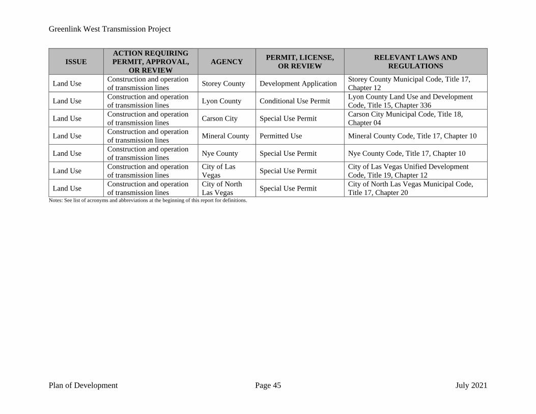
Greenlink West Transmission Project
Plan of Development Page 45 July 2021
ISSUE ACTION REQUIRING PERMIT, APPROVAL,
OR REVIEW AGENCY PERMIT, LICENSE,
OR REVIEW RELEVANT LAWS AND
REGULATIONS
Land Use Construction and operation of transmission lines Storey County Development Application Storey County Municipal Code, Title 17,
Chapter 12
Land Use Construction and operation of transmission lines Lyon County Conditional Use Permit Lyon County Land Use and Development
Code, Title 15, Chapter 336
Land Use Construction and operation of transmission lines Carson City Special Use Permit Carson City Municipal Code, Title 18,
Chapter 04
Land Use Construction and operation of transmission lines Mineral County Permitted Use Mineral County Code, Title 17, Chapter 10
Land Use Construction and operation of transmission lines Nye County Special Use Permit Nye County Code, Title 17, Chapter 10
Land Use Construction and operation of transmission lines
City of Las Vegas Special Use Permit City of Las Vegas Unified Development
Code, Title 19, Chapter 12
Land Use Construction and operation of transmission lines
City of North Las Vegas Special Use Permit City of North Las Vegas Municipal Code,
Title 17, Chapter 20 Notes: See list of acronyms and abbreviations at the beginning of this report for definitions.

Greenlink West Transmission Project
Plan of Development Page 46 July 2021
5.0 ENVIRONMENTAL COMPLIANCE
5.1 ENVIRONMENTAL COMPLIANCE MANAGEMENT
As the applicant and owner of the Greenlink West Transmission Project, NV Energy has the responsibility to construct, operate, and maintain the transmission line and associated facilities in compliance with all federal, state, and local regulations and permits, and in accordance with stipulations and conditions included in the BLM ROW Grant. In addition to the permit requirements, NV Energy has committed to several environmental protection measures that are designed to avoid and/or minimize potential adverse effects to the environment.
NV Energy will designate an Environmental Compliance Team to monitor construction activities and track compliance with the measures listed in this document, the BLM ROW Grant, and other permits. The Environmental Compliance Team for the Project and their respective responsibilities are identified in Table 9.
Environmental Compliance Team
NAME POSITION RESPONSIBILITIES Matt Johns Project Manager Project Management
Lee Simpkins Environmental Manager Permit Coordination Agency Coordination Compliance Reporting
Bill Kruger Land Resources Manager Property Owner Notification Terry Saunders Construction Administrator Construction Oversight
NV Energy will also rely on the expertise of on-site Environmental Inspectors during construction to ensure compliance with all Project requirements on an as-needed basis. The environmental inspection team will include specialists in various disciplines including, but not limited to, wildlife, cultural resources, botany, and paleontology. Additionally, there will be a team of desert tortoise specialists involved in all work within desert tortoise habitat. This team will include Desert Tortoise Authorized Biologists and Desert Tortoise Monitors who will coordinate with the construction crews any time work is occurring in desert tortoise habitat.
5.2 ENVIRONMENTAL PROTECTION MEASURES
NV Energy has committed to implementing the environmental protection measures listed in this section, which are divided into 12 categories: General Measures, Soil Disturbance, Blasting, Storm Water Management, Noxious Weeds, Vegetation, Water Features, Wildlife and Sensitive Species, Cultural and Paleontological Resources, Hazardous Materials and Waste, Air Quality, and Fire Prevention and Response.

Greenlink West Transmission Project
Plan of Development Page 47 July 2021
5.2.1 General Measures
1. The limits of the temporary work areas will be marked with staking and/or flagging. All environmentally sensitive areas, if any, will be fenced for avoidance.
2. Prior to construction, all construction personnel will be instructed on the protection of sensitive biological, cultural, and paleontological resources that have the potential to occur on site.
3. NV Energy will limit construction in residential areas to between daylight and dusk, seven days a week, subject to government entity requirements.
4. All construction vehicle movement will be restricted to the ROW, pre-designated access roads, and public roads.
5. Smoking will only be permitted in paved or cleared areas. All cigarettes will be thoroughly extinguished and disposed of in a trash receptacle.
6. Non-specular conductors will be installed to reduce visual impacts. 7. All existing roads will be left in a condition equal to or better than their pre-construction
condition.
5.2.2 Soil Disturbance
1. In areas where significant grading will be required for temporary construction, topsoil (where present) will be stockpiled and segregated for later reapplication.
2. Construction will be prohibited when the soil is too wet to adequately support construction equipment unless topsoil is removed and stockpiled. Construction may proceed in this case.
5.2.3 Blasting
1. At a minimum, all explosive storage facilities will be weather-resistant, fire-resistant, bullet-resistant, and theft-resistant.
2. Potential rockslide/landslide areas will be avoided to the maximum extent possible and a blasting geologist will be consulted prior to blasting in these areas.
3. Blasts will be designed to minimize ground vibrations that can cause slope instability and impacts to wells and/or springs.
4. Blasting within 500 feet of wells and/or springs will be avoided to the maximum extent possible.
5. Prior to blasting activities, all underground utilities will be located and marked to determine their location in relation to the ROW. NV Energy and/or its contractor will perform pre- and post-blast inspections of existing structures that may sustain damage due to blasting operations.
6. NV Energy and/or its contractor will take proper precautions to minimize or avoid damaging structures or utilities located within 150 feet of blasting operations. Precautions

Greenlink West Transmission Project
Plan of Development Page 48 July 2021
may include rippling the charge detonations further apart or reducing the amount of charge material that detonates simultaneously.
7. To prevent or minimize the amount of rock particles cast into the air following detonation, blasting mats will be used.
8. A signaling system will be used to alert individuals of an impending blast. The signaling system will include the following components:
• A warning signal: 5 minutes prior to the blasting signal, a 1-minute series of long audible signals will be sounded at the blast site.
• A blasting signal: 1 minute prior to the blast, a series of short, audible signals will be sounded at the blast site.
• An all-clear signal: a prolonged, audible signal will be sounded at the blast site following the post-blast inspection of the blast area.
9. To inform construction personnel of the signaling protocol, signs explaining the protocol will be posted at the staging areas and other appropriate locations.
10. If any damage to structures occurs due to blasting operations, NV Energy and/or its contractor will repair the damage as quickly as possible after becoming aware of the damage. In the event of damage to any water supply systems, NV Energy and/or its contractor will provide an alternative water source until the original water supply system is restored.
5.2.4 Stormwater Management
1. NV Energy will apply for a Stormwater Permit. NV Energy will develop a Stormwater Pollution Prevention Plan that incorporates Best Management Practices, typically in the form of straw waddles down gradient from disturbed Project areas and around spoil and stock piles.
5.2.5 Noxious Weeds
1. Prior to pre-construction activities, NV Energy personnel will identify all noxious weeds present on the land to be included in the ROW Grant and provide this information to the BLM. A determination will be made by the BLM of any noxious weeds that require flagging for treatment. NV Energy will treat the noxious weeds as required by the BLM.
2. All gravel and/or fill material will be certified as weed-free. 3. All off-road equipment will be cleaned (power or high-pressure cleaning) of all mud, dirt,
and plant parts prior to initially moving equipment onto public land. Equipment will be cleaned again if it leaves the Project site prior to reentry.
4. Disturbances to areas infested with noxious weeds will be avoided to the extent possible. 5. Any equipment or vehicles used in an area infested with noxious weeds will be thoroughly
cleaned before they are moved to a new location.

Greenlink West Transmission Project
Plan of Development Page 49 July 2021
6. As soon as work is completed, temporary disturbance areas will be seeded with an appropriate seed mix approved by the BLM (or other land managing agencies, as applicable) to establish ground cover by native species.
7. The Project area will be monitored annually for three years to identify new infestations of noxious weeds within the ROW. Any new infestations will be treated using methods approved by the BLM (or other land managing agencies, as applicable).
5.2.6 Vegetation
1. Wherever possible, vegetation will be left in place. Where vegetation must be removed, it will be cut at ground level to preserve the root structure and allow for potential resprouting.
2. All temporary construction areas, including stringing sites and structure pads that have been disturbed, will be recontoured and restored as required by the landowner or land management agency. The method of restoration typically will consist of seeding or revegetating with native plants (if required), installing cross drains for erosion control, and placing water bars in the road. Seed will be certified as weed-free and will consist of a seed mix approved by the BLM (or other land managing agencies, as applicable).
5.2.7 Water Features
1. All construction vehicles and equipment staging or storage and all construction activities will be located at least 100 feet away from any streams, wetlands, and other water features unless such features are adequately protected.
5.2.8 Wildlife and Sensitive Species
1. Prior to construction (inclusive of ROW clearing and access road construction), biological surveys of the ROW and the access roads will be conducted. Potential habitat for listed species identified during the pre-construction survey will be fenced for avoidance. If avoidance is infeasible, consultation with appropriate jurisdictional agencies will be conducted prior to work in the area(s).
2. Excavations left open overnight will be covered or fenced to prevent livestock or wildlife from falling in. All covers will be secured in place and strong enough to prevent livestock or wildlife from falling in.
3. If a sensitive plant or animal species is identified during construction, work near the sensitive species will be halted, and a qualified biologist familiar with the biology and species likely to be encountered in the Project area will be consulted to determine an appropriate buffer and other protective measures. The appropriate resource agencies will be notified of the discovery within 24 hours. If avoidance is infeasible, consultation with the jurisdictional resource agency will be conducted prior to continuing work in the immediate area of the species. Any federal- or state-listed species discovered on public land will also be reported to the BLM.

Greenlink West Transmission Project
Plan of Development Page 50 July 2021
4. Structures will be constructed to conform to those practices described in the Suggested Practices for Raptor Protection on Power Lines Manual developed by the Edison Electric Institute.
5.2.9 Cultural and Paleontological Resources
1. An initial intensive cultural resource inventory survey will be conducted prior to construction. Unevaluated cultural sites will be tested to determine their eligibility status. Wherever possible, NV Energy will avoid cultural sites identified as eligible for inclusion on the National Register of Historic Places. Where avoidance is not possible, a treatment plan will be developed through consultation between the BLM, State Historic Preservation Office (“SHPO”), and applicable tribes.
2. Prior to construction, NV Energy and/or its contractors will train workers and individuals involved with the Project regarding the potential to encounter historic or prehistoric sites and objects, proper procedures in the event that cultural items or human remains are encountered, prohibitions on artifact collection, and respect for Native American religious concerns. As part of this training, all construction personnel will be instructed to inspect for paleontological and cultural objects when excavating or conducting other ground-disturbing activities.
3. If potential resources are found, work will be halted immediately within a minimum distance of 300 feet from the discovery, and a professional archaeologist (holding a valid Cultural Resources Permit from Nevada BLM) will be mobilized to the site to evaluate the find. Any potential resources will not be handled or moved. The professional archaeologist will then determine whether the find needs to be evaluated by a paleontologist or Native American representative. The appropriate specialist(s) will then make a determination of the significance of the find and the steps to be followed before proceeding with the activity. Any cultural and/or paleontological resource discovered during construction on public or federal land will be reported immediately to the BLM. Work will not commence until the BLM issues a notice to proceed. The BLM will notify and consult with the SHPO and appropriate Tribes on eligibility and suitable treatment options. If significant resources are discovered, they will be recovered, transported, and stored at an approved curation facility that meets the standards specified in 36 C.F.R. 79.
4. If human remains are encountered during Project construction, all work within 300 feet of the remains will cease, and the remains will be protected. If the remains are on land managed by the BLM, BLM representatives will be immediately notified. If the remains are Native American, the BLM will follow the procedures set forth in 43 C.F.R. 10, Native American Graves Protection and Repatriation Regulations. If the remains are located on state or private lands, the Nevada SHPO and the BLM will be notified immediately. Native American human remains discovered on state or private lands will be treated under the provisions of the Protection of Indian Burial Sites section of the NRS in Chapter 383. The Nevada SHPO will consult with the Nevada Indian Commission and notify the appropriate Native American tribe. Procedures for inadvertent discovery are listed under NRS 383.170.

Greenlink West Transmission Project
Plan of Development Page 51 July 2021
5.2.10 Hazardous Materials and Waste
1. All construction vehicles will be maintained in accordance with the manufacturers’ recommendations. All vehicles will be inspected for leaks prior to entering the jobsite. All discovered leaks will be contained with a bucket or absorbent materials until repairs can be made.
2. All hazardous waste materials will be properly labeled in accordance with 40 C.F.R. 262. A list of hazardous materials expected to be used during construction of the Project is presented in Table 10.
Hazardous Materials Proposed for Project Use
HAZARDOUS MATERIAL 2-Cycle Oil Lubricating Grease ABC Fire Extinguisher Mastic Coating Acetylene Gas Methyl Alcohol
Air Tool Oil North Wasp and Hornet Spray (1,1,1-Trichloro-ethane)
Antifreeze Oxygen Automatic Transmission Fluid Paint Battery Acid Paint Thinner Bee Bop Insect Killer Petroleum Products Canned Spray Paint Prestone II Antifreeze Chain Lubricant (Methylene Chloride) Puncture Seal Tire Inflator Connector Grease Safety Fuses Contact Cleaner 2000 Safety Solvent Eye Glass Cleaner (Isopropyl Alcohol) Starter Fluid Gas Treatment Wagner Brake Fluid Gasoline WD-40 Insulating Oil Diesel Fuel
3. Hazardous material storage, equipment refueling, and equipment repair will be conducted at least 100 feet away from streams or other water features.
4. Spilled material of any type will be cleaned up immediately. A shovel and spill kit will be maintained on site at all times to respond to spills.
5. All sanitary wastes will be collected in portable, self-contained toilets at all construction staging areas and other construction operation areas and managed in accordance with local requirements.
5.2.11 Air Quality
1. Driving speeds will be limited to 25 miles per hour on unpaved roads and on the ROW. 2. All areas subject to ground disturbance will be watered and/or treated with authorized dust
palliative as needed to control dust.
Greenlink West Transmission Project
Plan of Development Page 52 July 2021
3. Public streets will be swept if visible soil material is tracked onto them by construction vehicles.
4. Excavation and grading activities will be suspended when winds (instantaneous gusts) exceed 50 miles per hour and visible dust that creates a health hazard to neighboring property owners and/or visibility impacts to vehicular traffic persists.
5.2.12 Fire Prevention and Response
1. NV Energy will designate a Fire Marshal (NV Energy Fire Marshal), who will coordinate with the BLM’s fire management representative, as necessary.
2. The Fire Marshal will be responsible for the following tasks:
• Conducting regular inspections of tools, equipment, and first aid kits for completeness.
• Conducting regular inspections of storage areas and practices for handling flammable fuels to confirm compliance with applicable laws and regulations.
• Posting smoking and fire rules at centrally visible locations on site.
• Coordinating initial response to contractor-caused fires within the ROW.
• Conducting fire inspections along the ROW.
• Ensuring that all construction workers and subcontractors are aware of all fire protection measures.
• Remaining on duty and on site when construction activities are in progress and during any additional periods when fire safety is an issue, or designating another individual to serve in this capacity when absent.
• Reporting all wildfires in accordance with the notification procedures described below.
• Initiating and implementing fire suppression activities until relieved by agency or local firefighting services in the event of a Project-related fire. Project fire suppression personnel and equipment, including water tenders, will be dispatched within 15 minutes from the time that a fire is reported.
• Coordinating with the NV Energy Project Manager regarding current fire conditions potential and fire safety warnings from the BLM and communicating these to the contractor’s crews.
3. NV Energy’s Construction Foreman or Fire Marshal will immediately notify firefighting services of any fires on site. A list of emergency fire contacts for the Project area is presented in Table 11.

Greenlink West Transmission Project
Plan of Development Page 53 July 2021
Emergency Fire Contacts
CALL 911 FIRST Department Phone Number
BLM Sierra Front Interagency Dispatch Center (775) 883-3535 for Emergencies (Fire Management Office) (775) 883-5995 for Administration
4. Contractors will be notified to stop or reduce construction activities that pose a significant fire hazard until appropriate safeguards are taken.
5. If an accidental fire occurs during construction, immediate steps to extinguish the fire (if it is manageable and safe to do so) will be taken using available fire suppression equipment and techniques. Fire suppression activities will be initiated by NV Energy and/or its contractor until relieved by agency or local firefighting services.
6. Smoking will only be permitted in designated cleared areas and will be prohibited while walking or working in areas with vegetation or while operating equipment. In areas where smoking is permitted, all burning tobacco and matches will be completely extinguished and discarded in ash trays, not on the ground.
7. “NO SMOKING” signage and fire rules will be posted at construction staging areas, helicopter fly yards, and key construction sites during the fire season.
8. Fire suppression equipment will be present in areas where construction tools or equipment have the potential to spark a fire.
9. Extra precautions will be taken when fire danger is considered to be high. 10. All field personnel will be instructed regarding emergency fire response. The contractors
will receive training on the following:
• Initial fire suppression techniques.
• Fire event reporting requirements.
• Methods to determine if a fire is manageable.
• Fire control measures to be implemented by field crews on site.
• When the worksite should be evacuated.
• How to respond to wildfires in the vicinity.
• How to maintain knowledge of and plans for evacuation routes.
11. All flammable material, including dead vegetation, dry grasses, and snags (fallen or standing dead trees), will be cleared a minimum of 10 feet from areas of equipment operation that may generate sparks or flames.
12. No open burning, campfires, or barbeques will be allowed along the ROW; at construction staging areas, helicopter fly yards, and substations; on access roads; or in any other Project-related construction areas.

Greenlink West Transmission Project
Plan of Development Page 54 July 2021
13. All welding or cutting of power line structures or their component parts will be approved by NV Energy’s Construction Foreman or Administrator. Approved welding or cutting activities will only be performed in areas cleared of vegetation a minimum of 10 feet around the area. Welding or cutting activities will cease one hour before all fire response personnel leave a construction area to reduce the possibility of welding activities smoldering and starting a fire. Welder vehicles will be equipped with fire suppression equipment.
14. All internal combustion engines, both stationary and mobile, will be equipped with approved spark arresters that have been maintained in good working condition. Light trucks and cars with factory-installed (type) mufflers in good condition may be used on roads cleared of all vegetation with no additional equipment required. Vehicles equipped with catalytic converters are potential fire hazards and will be parked on cleared areas only.
15. The use of torches, fuses, highway flares, or other warning devices with open flames will be prohibited. NV Energy and its contractors will only use electric or battery-operated warning devices on site.
16. Equipment parking areas, small stationary engine sites, and gas and oil storage areas will be cleared of all extraneous flammable materials. “NO SMOKING” signs will be posted in these areas at all times.
17. Fuel tanks will be grounded. 18. NV Energy and its contractors will provide continuous access to roads for emergency
vehicles during construction. 19. All motorized vehicles and equipment will be equipped with the following fire protection
items:
• One long-handled round-point shovel.
• One ax or Pulaski fire tool.
• One 5-pound ABC Dry Chemical Fire Extinguisher.
• One 5-gallon water backpack (or other approved container) full of water or other extinguishing solution.
• Hard hat, work gloves, and eye protection. 20. Project construction worksites will include the following equipment:
• Power saws, if required for construction, equipped with an approved spark arrester and accompanied by one 5-pound ABC Dry Chemical Fire Extinguisher and a long-handled, round-point shovel when used away from a vehicle.
• Fuel service trucks with one 35-pound capacity fire extinguisher charged with the necessary chemicals to control electrical and fuel fires.
• At least two long-handled, round-point shovels and two 5-pound ABC Dry Chemical Fire Extinguishers at wood cutting, welding, or other construction work sites that have a high risk of starting fires.

Greenlink West Transmission Project
Plan of Development Page 55 July 2021
• At least one radio and/or cellular telephone to contact fire suppression agencies or the Project management team.
• Backpumps filled with water (two at each wood cutting site, one at each welding site, and two at each tower installation or construction site, or any activity site at risk of igniting fires).
21. During periods of increased fire danger, a fire suppression vehicle will be available in the construction area or stationed near high-risk construction work sites and will be equipped with the following items:
• One water tank with a minimum capacity of 500 gallons.
• 250 feet of 0.75-inch heavy-duty rubber hosing.
• One pump with a discharge capacity of at least 20 gallons per minute. (The pump will have fuel capacity to operate for at least a 2-hour period.)
• One tool cache (for fire use only) containing at a minimum: - Two long-handled round-point shovels. - Two axes or Pulaski fire tools. - One chainsaw of 3.5 (or more) horsepower with a cutting bar of at least 20
inches in length. 22. If a fire is unmanageable, field crews will evacuate and call “911” or the district dispatch
for the area (see Table 11). All fires will be reported to the jurisdictional fire agency, regardless of size and action taken.
6.0 REFERENCES
Bureau of Land Management (BLM). 2012a. Final Solar Energy Development Programmatic Environmental Impact Statement, United States Bureau of Land Management, Information Center. Final Solar Energy Development Programmatic EIS (anl.gov). July 2012.
_____. 2012b. Final Solar Energy Development Programmatic Environmental Impact Statement, Executive Summary; page ES.37, United States Bureau of Land Management, Information Center.
_____. 2012c. Final Solar Energy Development Programmatic Environmental Impact Statement, Volume 4: Chapter 11, Nevada Solar Energy Zones, United States Bureau of Land Management, Information Center.
Public Utility Commission of Nevada (Commission). 2009. Order - Docket No. 09-07011; September 28, 2009.
_____. 2019. Second Amendment to 2018 Integrated Resource Plan; Testimony of Sachin Verma; May 1, 2019; page 195. Public Utilities Commission of Nevada Electronic Filing. May 1, 2019.
Greenlink West Transmission Project
Plan of Development Page 56 July 2021
United States Department of Energy (DOE) and Bureau of Land Management (BLM). 2008. Guide to the West-Wide Energy Corridor Final Programmatic Environmental Impact Statement (PEIS). West-wide Energy Corridor Final PEIS Annotated Guide (anl.gov). November 2008.


