Neutronic and Burnup Studies of Accelerator-driven Systems ...14665/FULLTEXT01.pdf · Burnup in a...
140
Neutronic and Burnup Studies of Accelerator-driven Systems Dedicated to Nuclear Waste Transmutation Kamil Tuˇ cek Stockholm 2004 Doctoral Thesis Royal Institute of Technology Department of Physics
Transcript of Neutronic and Burnup Studies of Accelerator-driven Systems ...14665/FULLTEXT01.pdf · Burnup in a...

Neutronic and Burnup Studies of
Accelerator-driven Systems
Dedicated to Nuclear Waste Transmutation
Kamil Tucek
Stockholm 2004
Doctoral ThesisRoyal Institute of Technology
Department of Physics

Akademisk avhandling som med tillstand av Kungl Tekniska Hogskolan framlaggestill offentlig granskning for avlaggande av teknisk doktorsexamen fredagen den3 december 2004 kl 10.00 i sal FA32, AlbaNova universitetscentrum, Kungl TekniskaHogskolan, Roslagstullsbacken 21, Stockholm.
ISBN 91-7283-890-6TRITA-FYS 2004:68ISSN 0280-316XISRN KTH/FYS/–04:68–SE
c© Kamil Tucek, November 2004
Printed by Universitetsservice US-AB, Stockholm 2004

Abstract
Partitioning and transmutation of plutonium, americium, and curium is inevitableif the radiotoxic inventory of spent nuclear fuel is to be reduced by more than afactor of 100. But, admixing minor actinides into the fuel severely degrades systemsafety parameters, particularly coolant void reactivity, Doppler effect, and (effec-tive) delayed neutron fractions. The incineration process is therefore envisioned tobe carried out in dedicated, accelerator-driven sub-critical reactors (ADS). How-ever, ADS cores operating in concert with light-water reactors (two-componentscenario) also exhibit high burnup reactivity swing with penalty on the systemperformance/economy.
In the frame of this design work, we attempted, by choice of coolant and opti-misation of fuel concept and core design, to achieve favourable neutronic, burnupand safety characteristics of the transuranium ADS burner. Key thermal hydraulicand material-related constraints were respected.
A novel fuel matrix material, hafnium nitride, was identified as an attractivediluent option for highly reactive transuranics. (TRU,Hf)N fuels appeared to havea good combination of neutronic, burnup and thermal characteristics: maintain-ing hard neutron spectra, yielding acceptable values of coolant void reactivity andsource efficiency, and providing small burnup reactivity loss. A conceptual designof a (TRU,Hf)N fuelled, lead/bismuth eutectic cooled ADS was developed. The av-erage discharge burnup of 20% fissions per initial metal atom could be reached evenwithout fuel reshuffling. The fission fraction ratios of even-neutron number ameri-cium nuclides are increased by a factor of two in comparison to burners with inertmatrix based fuels. Hence, thanks to the reduced production of higher actinidesand helium, fuel cycle economy is improved.
The coolant void worth proved to be a strong function of the fuel composition -reactor cores with high content of fertile material or minor actinides in fuel exhibitlarger void reactivities than systems with plutonium-rich, inert matrix fuels. Inreactor systems cooled by lead/bismuth eutectic, a radial steel pin reflector signif-icantly lowered coolant void reactivity. For transuranic fuel, fertile and stronglyabsorbing matrices exhibited increasing void worth with increasing pitch, while theopposite was valid for the coolant void worth of inert matrix fuels. Large pitchesalso appeared to be beneficial for limiting the reactivity worth of the cladding ma-terial and improving source efficiency.
The economy of the source neutrons was investigated as a function of core andtarget design. An incentive to design the core with as low target radius as allowableby the thermal constraints posed by the ability to dissipate accelerator beam powerwas identified.
ISBN 91-7283-890-6 • TRITA-FYS 2004:68 • ISSN 0280-316X • ISRN KTH/FYS/–04:68–SE
iii

iv

List of Papers
I. K. Tucek, J. Wallenius, and W. GudowskiCoolant void worth in fast breeder reactors and accelerator-driven transura-nium and minor-actinide burnersAnnals of Nuclear Energy, 31, 1783 (2004)
II. K. Tucek, M. Jolkkonen, J. Wallenius, and W. GudowskiNeutronic and burnup studies of an accelerator-driven transuranium burnerin a start-up modeSubmitted to Nuclear Technology (2004)
III. J. Wallenius, K. Tucek, J. Carlsson, and W. GudowskiApplication of burnable absorbers in an accelerator driven systemNuclear Science and Engineering, 137, 96 (2001)
IV. K. Tucek, J. Wallenius, and W. GudowskiOptimal distribution of fuel, poisons and diluents in sub-critical cores dedi-cated to waste transmutationIn Proceedings of the International Conference on Emerging Nuclear EnergySystems, ICENES 00, Petten, NRG (2000)
V. P. Seltborg, J. Wallenius, K. Tucek, and W. GudowskiDefinition and application of proton source efficiency in accelerator-drivensystemsNuclear Science and Engineering, 145, 390 (2003)
Papers which are not included in the thesis:
VI. K. Tucek, J. Wallenius, W. Gudowski and A. SoltanIAEA accelerator driven system neutronic benchmarkIn Feasibility and Motivation for Hybrid Concepts for Nuclear EnergyGeneration and Transmutation, IAEA-TC-903.3, CIEMAT (1998)
v

vi List of Papers
VII. J. Wallenius, K. Tucek, and W. GudowskiTechnetium-99 neutron absorbers in the reflector of Pb/Bi cooled reactorsIn Proceedings of Heavy Liquid Metal Coolants in Nuclear Technology,HLMC 98, IPPE Obninsk, Russia (1998)
VIII. K. Tucek, J. Wallenius, W. Gudowski, and C. SandersBurnup in a sub-critical system with flat power densityIn Proceedings of the Third International Conference on Accelerator-Driven Transmutation Technologies and Applications, ADTTA 99, Praha(1999)
IX. J. Wallenius, K. Tucek, W. Gudowski, and C. SandersNeutronics of a sub-critical system burning non-recycled LWR wasteIn Proceedings of the Third International Conference on Accelerator-Driven Transmutation Technologies and Applications, ADTTA 99, Praha(1999)
X. J. Wallenius, K. Tucek, and W. GudowskiSafety analysis of nitride fuels in cores dedicated to waste transmutationIn Proceedings of the Sixth International Information Exchange Meeting,Actinide and Fission Product Partitioning and Transmutation, Madrid,OECD/NEA (2000)
XI. M. Eriksson, J. Wallenius, K. Tucek, and W. GudowskiPreliminary safety analysis of a Swedish accelerator driven system employ-ing nitride fuel and burnable absorbersIn Proceedings of the Technical Committee Meeting on Core Physics andEngineering Aspects of Emerging Nuclear Energy Systems for Energy Gen-eration and Transmutation, Argonne National Laboratory (2000)
XII. K. Tucek, J. Wallenius, and W. GudowskiSource efficiency in an accelerator-driven system with burnable absorbersIn Proceedings of the International Conference on Back-End of the FuelCycle: From Research to Solutions, GLOBAL 2001, Paris, ANS (2001)
XIII. D. Westlen, W. Gudowski, J. Wallenius, and K. TucekA cost benefit analysis of an accelerator driven transmutation systemIn Proceedings of AccApp/ADTTA’01, Reno, USA, ANS (2001)
XIV. J. Cetnar, W. Gudowski, J. Wallenius, and K. TucekSimulation of nuclide transmutations with Monte-Carlo continuousenergy burnup code (MCB1C)In Proceedings of AccApp/ADTTA’01, Reno, USA, ANS (2001)

List of Papers vii
XV. M. Eriksson, J. Wallenius, J.E. Cahalan, K. Tucek, and W. GudowskiSafety analysis of Na and Pb-Bi coolants in response to beam instabilitiesIn Proceedings of the Third International Workshop on Utilisation and Re-liability of High Power Proton Accelerators, Santa Fe, USA (2002)

viii

Acknowledgments
I would like to express my gratitude to
• Waclaw Gudowski for inviting me to work on transmutations at the Royal In-stitute Institute of Technology, for his support and encouragement throughoutthe years.
• Frantisek Janouch for bringing me to Sweden, for his constant interest andenthusiasm initiating long discussions on any subject.
• Janne Wallenius for useful suggestions and valuable remarks.
• my colleagues, old and present, from the Department of Nuclear and ReactorPhysics for providing a creative, friendly and relaxed atmosphere; particularthanks to Mikael Jolkkonen and Patrick Isaksson for linguistic advice.
• Lvıcek and all other friends which made my stay here so enjoyable and cheer-ful.
Finally, most thanks go to my wonderful parents. Dekuji vam za vsechno!
I acknowledge the financial support by the Swedish Nuclear Fuel and Waste Man-agement Co. (SKB AB) and the Swedish Institute.
Stockholm, November 12, 2004
Kamil Tucek
ix

x

Contents
List of Papers v
1 Introduction 31.1 Background . . . . . . . . . . . . . . . . . . . . . . . . . . . . . . . 31.2 Thesis overview . . . . . . . . . . . . . . . . . . . . . . . . . . . . . 51.3 Author’s contribution . . . . . . . . . . . . . . . . . . . . . . . . . 6
2 Nuclear waste 72.1 Fission process . . . . . . . . . . . . . . . . . . . . . . . . . . . . . 72.2 Spent fuel composition . . . . . . . . . . . . . . . . . . . . . . . . . 102.3 Radiotoxic inventory . . . . . . . . . . . . . . . . . . . . . . . . . . 132.4 Spent fuel management . . . . . . . . . . . . . . . . . . . . . . . . 152.5 Repository performance . . . . . . . . . . . . . . . . . . . . . . . . 162.6 Defining goals for P&T . . . . . . . . . . . . . . . . . . . . . . . . 16
3 Partitioning & Transmutation 193.1 Partitioning . . . . . . . . . . . . . . . . . . . . . . . . . . . . . . . 20
3.1.1 Aqueous methods . . . . . . . . . . . . . . . . . . . . . . . . 203.1.2 Pyrochemical methods . . . . . . . . . . . . . . . . . . . . . 22
3.2 Transmutation . . . . . . . . . . . . . . . . . . . . . . . . . . . . . 233.2.1 Equilibrium fuel cycle . . . . . . . . . . . . . . . . . . . . . 233.2.2 Net consumption . . . . . . . . . . . . . . . . . . . . . . . . 253.2.3 Neutron economy . . . . . . . . . . . . . . . . . . . . . . . . 263.2.4 Safety aspects . . . . . . . . . . . . . . . . . . . . . . . . . . 273.2.5 Reactivity temperature coefficients . . . . . . . . . . . . . . 273.2.6 Coolant temperature reactivity coefficient and
void worth . . . . . . . . . . . . . . . . . . . . . . . . . . . 293.2.7 Neutron slowing down . . . . . . . . . . . . . . . . . . . . . 313.2.8 Feedback through material dilatation . . . . . . . . . . . . . 353.2.9 Doppler feedback . . . . . . . . . . . . . . . . . . . . . . . . 373.2.10 Delayed neutron fractions . . . . . . . . . . . . . . . . . . . 39
3.3 Transmutation strategies . . . . . . . . . . . . . . . . . . . . . . . . 41
xi

xii Contents
3.3.1 Thermal reactors . . . . . . . . . . . . . . . . . . . . . . . . 423.3.2 Fast reactors . . . . . . . . . . . . . . . . . . . . . . . . . . 473.3.3 Scenarios . . . . . . . . . . . . . . . . . . . . . . . . . . . . 50
4 Dedicated reactors 534.1 Critical actinide burners . . . . . . . . . . . . . . . . . . . . . . . . 534.2 Accelerator-driven systems . . . . . . . . . . . . . . . . . . . . . . . 544.3 Review of ADS related projects . . . . . . . . . . . . . . . . . . . . 54
4.3.1 Japan . . . . . . . . . . . . . . . . . . . . . . . . . . . . . . 554.3.2 France . . . . . . . . . . . . . . . . . . . . . . . . . . . . . . 554.3.3 U.S.A. . . . . . . . . . . . . . . . . . . . . . . . . . . . . . . 564.3.4 CERN . . . . . . . . . . . . . . . . . . . . . . . . . . . . . . 564.3.5 EU related projects . . . . . . . . . . . . . . . . . . . . . . 56
4.4 Role of ADS in P&T schemes . . . . . . . . . . . . . . . . . . . . . 57
5 Choice of materials for ADS 595.1 Fuel . . . . . . . . . . . . . . . . . . . . . . . . . . . . . . . . . . . 59
5.1.1 Nitride fuel . . . . . . . . . . . . . . . . . . . . . . . . . . . 605.1.2 Diluent for nitride fuel . . . . . . . . . . . . . . . . . . . . . 625.1.3 Metallic fuel . . . . . . . . . . . . . . . . . . . . . . . . . . 635.1.4 Oxide fuel . . . . . . . . . . . . . . . . . . . . . . . . . . . . 64
5.2 Coolant . . . . . . . . . . . . . . . . . . . . . . . . . . . . . . . . . 645.3 Construction material . . . . . . . . . . . . . . . . . . . . . . . . . 665.4 Neutron absorber . . . . . . . . . . . . . . . . . . . . . . . . . . . . 66
6 Neutronic and burnup aspects of TRU incineration 696.1 Design challenges . . . . . . . . . . . . . . . . . . . . . . . . . . . . 69
6.1.1 Reactivity loss . . . . . . . . . . . . . . . . . . . . . . . . . 706.1.2 Power peaking . . . . . . . . . . . . . . . . . . . . . . . . . 716.1.3 Burnup reactivity swing & coolant void worth . . . . . . . . 71
6.2 Source efficiency . . . . . . . . . . . . . . . . . . . . . . . . . . . . 726.2.1 Axial position of beam impact . . . . . . . . . . . . . . . . 756.2.2 Target radius . . . . . . . . . . . . . . . . . . . . . . . . . . 766.2.3 Coolants . . . . . . . . . . . . . . . . . . . . . . . . . . . . . 77
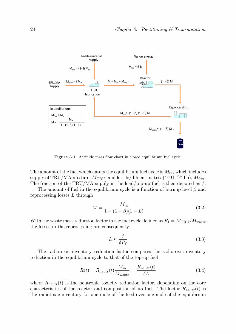
6.3 Neutronic performance . . . . . . . . . . . . . . . . . . . . . . . . . 776.4 Safety performance . . . . . . . . . . . . . . . . . . . . . . . . . . . 80
6.4.1 Coolant void worth . . . . . . . . . . . . . . . . . . . . . . . 806.4.2 Cladding worth . . . . . . . . . . . . . . . . . . . . . . . . . 836.4.3 Reactivity temperature feedbacks . . . . . . . . . . . . . . . 836.4.4 Effective delayed neutron fractions . . . . . . . . . . . . . . 85
6.5 Burnup performance . . . . . . . . . . . . . . . . . . . . . . . . . . 856.6 Influence of increased pitch-to-diameter ratio . . . . . . . . . . . . 86
6.6.1 Source efficiency . . . . . . . . . . . . . . . . . . . . . . . . 876.6.2 Coolant void and cladding worth . . . . . . . . . . . . . . . 88

Contents xiii
6.6.3 Burnup performance . . . . . . . . . . . . . . . . . . . . . . 906.7 Homogeneous vs. heterogeneous modelling . . . . . . . . . . . . . . 90
7 Design of a TRU ADS burner 937.1 Core concept . . . . . . . . . . . . . . . . . . . . . . . . . . . . . . 937.2 Down-selections of core materials . . . . . . . . . . . . . . . . . . . 94
7.2.1 Fuel . . . . . . . . . . . . . . . . . . . . . . . . . . . . . . . 947.2.2 Diluent material . . . . . . . . . . . . . . . . . . . . . . . . 947.2.3 Coolant . . . . . . . . . . . . . . . . . . . . . . . . . . . . . 94
7.3 Design constraints . . . . . . . . . . . . . . . . . . . . . . . . . . . 957.4 Design employing HfN . . . . . . . . . . . . . . . . . . . . . . . . . 957.5 Design employing B4C . . . . . . . . . . . . . . . . . . . . . . . . . 101
8 Papers 1058.1 Paper I . . . . . . . . . . . . . . . . . . . . . . . . . . . . . . . . . 1058.2 Paper II . . . . . . . . . . . . . . . . . . . . . . . . . . . . . . . . . 1058.3 Paper III . . . . . . . . . . . . . . . . . . . . . . . . . . . . . . . . 1068.4 Paper IV . . . . . . . . . . . . . . . . . . . . . . . . . . . . . . . . 1068.5 Paper V . . . . . . . . . . . . . . . . . . . . . . . . . . . . . . . . . 107
9 Conclusions 109

xiv

Nomenclature
ABR Actinide Burner ReactorADS Accelerator-driven SystemAFCI Advanced Fuel Cycle InitiativeALMR Advanced Liquid Metal ReactorAn ActinideATR Advanced Test ReactorATW Accelerator Transmutation of WasteBA Burnable AbsorberBOC Beginning-Of-CycleBOL Beginning-Of-LifeBWR Boiling Water ReactorCERCER CERamic-CERamic fuelCERMET CERamic-METallic fuelCAPRA Consommation Accrue de Plutonium en Recteur rApideCEA Commissariat a l’Energi AtomiqueCMS Centre-of-mass systemCNRS Centre National de la Recherche ScientifiqueDIAMEX DIAMide EXtractionDIDPA Di-IsoDecylPhosphoric Aciddpa-NRT Displacement per atom (Norgett, Robinson, Torrens)EdF Electricite de FranceEFR European Fast ReactorEFTTRA Experimental Feasibility of Targets for TRAnsmutationENDF Evaluated Nuclear Data FileEOC End-Of-CycleEOL End-Of-LifeFBuR Fast Burner ReactorFIMA Fissions per Initial Metal AtomFTF Flat-to-FlatFP Fission Productfpd Full power dayefpy Effective full power yearFR Fast Reactor
xv

xvi Nomenclature
GEDEPEON GEstion des DEchets et Production d’Energie par des OptionsNouvelles
GWd Giga-watt dayGWe Giga-watt electricGWth Giga-watt thermalHLW High Level WasteHLLW High Level Liquid WasteICRP International Commission on Radiation ProtectionIFR Integral Fast ReactorITU Institute for TransUranium elementsJAERI Japan Atomic Energy Research InstituteJEF Joint European FileJENDL Japanese Evaluated Nuclear Data FileKAERI Korea Atomic Energy Research InstituteLANL Los Alamos National LaboratoryLBE Lead-Bismuth EutecticLINAC LINear ACceleratorLLFP Long-lived Fission ProductLWR Light Water ReactorMA Minor ActinideMCB Monte Carlo Continuous energy Burnup codeMCNP Monte Carlo N-Particle codeMCNPX Monte Carlo N-Particle code eXtendedMOX Mixed OXide fuelMWth Mega-watt thermalN/A Not AvailableNEA Nuclear Energy Agency of OECDOECD Organisation for Economic Co-operation and DevelopmentOMEGA Options Making Extra Gain from Actinides and fission productsP/D Pitch-to-Diameter ratioP&T Partitioning and TransmutationPb/Bi Lead-Bismuth EutecticPSI Paul Scherrer InstitutePUREX Plutonium Uranium Recovery by EXtractionPWR Pressurised Water ReactorS/A Sub-assemblySAD Sub-critical Assembly DubnaSPIN SeParation-INcinerationtHM Metric tonne of Heavy MetalTRPO TRialkyl Phosphine OxideTRU TRansUranic elementTRUEX TRansUranium EXtractionTWhe Tera-watt hour electricUOX Uranium OXide fuel

Nomenclature xvii
XADS EXperimental Accelerator-Driven SystemXADT EXperimental Accelerator-Driven Transmutation

xviii

We know only a single science, the science of history.
Karl Marx (The German Ideology, 1846)
The History of the Universein 200 Words or Less
Quantum fluctuation. Inflation. Expansion. Strong nuclear in-teraction. Particle-antiparticle annihilation. Deuterium and he-lium production. Density perturbations. Recombination. Black-body radiation. Local contraction. Cluster formation. Reionisa-tion? Violent relaxation. Virialisation. Biased galaxy formation?Turbulent fragmentation. Contraction. Ionisation. Compression.Opaque hydrogen. Massive star formation. Deuterium ignition.Hydrogen fusion. Hydrogen depletion. Core contraction. En-velope expansion. Helium fusion. Carbon, oxygen, and siliconfusion. Iron production. Implosion. Supernova explosion. Metalsinjection. Star formation. Supernova explosions. Star forma-tion. Condensation. Planetesimal accretion. Planetary differen-tiation. Crust solidification. Volatile gas expulsion. Water con-densation. Water dissociation. Ozone production. Ultraviolet ab-sorption. Photosynthetic unicellular organisms. Oxidation. Mu-tation. Natural selection and evolution. Respiration. Cell differ-entiation. Sexual reproduction. Fossilisation. Land exploration.Dinosaur extinction. Mammal expansion. Glaciation. Homo sapi-ens manifestation. Animal domestication. Food surplus produc-tion. Civilisation! Innovation. Exploration. Religion. Warringnations. Empire creation and destruction. Exploration. Colonisa-tion. Taxation without representation. Revolution. Constitution.Election. Expansion. Industrialisation. Rebellion. Emancipa-tion Proclamation. Invention. Mass production. Urbanisation.Immigration. World conflagration. League of Nations. Suffrageextension. Depression. World conflagration. Fission explosions.United Nations. Space exploration. Assassinations. Lunar ex-cursions. Resignation. Computerisation. World Trade Organisa-tion. Terrorism. Internet expansion. Reunification. Dissolution.World-Wide Web creation. Composition. Extrapolation?
Reprinted from Annals of Improbable Research, 3, 27 (1997)


Chapter 1
Introduction
1.1 Background
In the present state of scientific knowledge, about 13.7 billions of years ago, some10−33 to 10−4 s after the Big Bang, the protons and neutrons were created in baryo-genesis process, hence marking the beginning of the Nuclear Age [1]. However, ittook another 105.5 years for first hydrogen atom to be formed, 100-200 million yearsfor stars to be born, and some millions of years for the first supernova to explodespreading heavy elements like carbon, nitrogen, oxygen, and uranium throughoutthe entire Universe. At least 4.6·109 years ago, such a supernova explosion occurredin the vicinity of our present Solar system, providing the primordial material forits formation.
This entire historical prologue was unknown for glassmen around the village ofJachymov (St. Joachimsthal) in the Bohemian Sudetenland as they, in the middleages, started to use the shiny black mineral coming as a waste from local silvermines in the production of yellow coloured glass and ceramics products. An excitingmystery has been covered in these rocks, called by German miners pechblende, i.e.“bad luck mineral”, until they came into the hands of one of the greatest scientistsof his time, Henri Becquerel. In 1896, he discovered that the invisible rays emittedby these uranium rocks (a phenomenon he called radioactivity) are responsible forexposure of photographic plates [2].
But the major discovery was to come in December 1938. German chemists OttoHahn and Fritz Strassmann reported that barium, an element lighter than uranium,was found in the neutron irradiated uranium samples [3]. It was Lise Meitner andher nephew Otto Frisch who first interpreted these results as a disintegration ofthe uranium nucleus and proposed a name for this phenomenon - fission [4]. Ashort time afterwards, Frisch and others demonstrated that the overall energeticbalance of the fission reaction is positive, and that the major amount of energy ismanifested as kinetic energy of the fission products. In 1939, Kowarski showed that
3

4 Chapter 1. Introduction
Figure 1.1. Ideas how to manage spent nuclear fuel have reached maturity sincethe 50s [8].
about three neutrons are liberated in one fission reaction [5, 6], which finally openedthe gate for construction of a self-sustainable nuclear energy producing device.
In the shadow of World War Two, the atomic era took off as a race on the trackof nuclear weapon development. Americans, being the first to succeed in 1945 andhaving reached considerable achievements in nuclear weapons (thermonuclear bombin 1952) and naval reactor designs (the first nuclear driven submarine Nautiluswas launched in January 1954), started to refocus their interests into the peacefulutilisation of atomic power. President Eisenhower’s “Atoms for Peace” speech onDecember 8, 1953 and Soviet pledge of help in expanding the nuclear technologyin the Eastern Block countries in 1955 had unlocked the doors to a massive andintensive development of nuclear energy on a commercial scale.
And anticipations were quite high - atomic power was supposed to turn riversand blast valleys as well as drive rail engines and aircrafts [7]. The management ofnuclear waste was similarly ambitious - such projects as dumping of nuclear wastesinto the sea and launching them out into the space in rockets or depositing thewaste in a seabed could be found among the proposals (Figure 1.1).
During the 60s and 70s, the spectrum of nuclear power utilisation narrowedsignificantly, converging into more realistic projects and focusing on designs ofreactors for commercial and military purposes. Waste management strategies hadgot down to earth, too. Plans for geological repository were put forth proposing tobury spent nuclear fuel in deep geological formations. Such projects are under wayin many countries, notably U.S.A., Sweden, and Switzerland. The moral, safety

1.2. Thesis overview 5
and economic issues of this waste management option are widely discussed andespecially the long-term safety of such repositories has become a major concern ofenviromentalists and the general public [9].
Indeed, the safety of an underground repository is a complex function of theendurance of natural and technical barriers as well as of its volume and contentof disposed nuclear waste. In the past two decades, several projects aiming to re-duce the volume and content of spent nuclear fuel have taken shape and have beengathered under the general banner ”partitioning and transmutation technologies”(P&T). The common denominator of all these projects is the use of an externalradiation source (nuclear reactor, accelerator, or both) producing particles (neu-trons, gammas, protons, etc) which in a controlled manner incinerate (transmute)certain nuclides separated/partitioned from spent fuel. Partitioning techniques aresometimes considered alone as a process of better spent fuel conditioning beforefinal disposal. It is believed that gradual phase-in of P&T technologies into theexisting fuel cycle could reduce the risks associated with spent fuel managementprior to geological disposal and the long-term radiological and radiotoxic impact ofthe repository on the environment.
1.2 Thesis overview
This thesis investigates in part the feasibility of deploying accelerator-driven sys-tems (ADS) as a part of a P&T scheme into the existing nuclear fuel cycle and theirinfluence on the long-term safety performance of the geological repository. Moreexplicitly, an attempt is made to achieve, by choice of coolant, fuel concept and coredesign, favourable neutronic, burnup and safety characteristics of the transuraniumADS burner. In pursuit of this goal, a conceptual design design of an ADS burneremploying innovative (TRU,Hf)N fuel was developed in Paper II. Preparatory,design scoping studies, with respect to the coolant void worth and source efficiencywere performed in Papers I and IV, respectively. In Paper V, a novel theoreticalframework to describe the source multiplication in ADS was presented. Paper IIIinvestigated the feasibility of a massive introduction of a neutron absorber (B4C)in ADS.
We begin with a presentation of the basic waste parameters of spent nuclearfuel and introduce the reader into the issue of radiotoxic fuel inventory in Chap-ter 2. Chapter 3 discusses the physical prerequisites for efficient transmutation oftransuranics in P&T schemes and provides an overview of existing spent fuel trans-mutation strategies. A brief description of accelerator-driven systems and projectsin this field then follows in Chapter 4. The choice of fuel, diluent matrix, claddingand coolant materials for ADS is discussed in Chapter 5. Chapter 6 accounts forneutronic, safety and burnup characteristics regarding TRU incineration in ADS.Conceptual designs of nitride fuelled lead-bismuth cooled TRU ADS burners withHfN fuel matrix and B4C absorbers are presented in Chapter 7. Finally, Chapter 8summarises the results presented in the appended papers.

6 Chapter 1. Introduction
1.3 Author’s contribution
The author of the thesis is the principal author of Papers I, II and IV. Hedeveloped the framework of the study, performed neutronic, burnup and thermalhydraulic calculations, analysed and interpreted results. The author participatedin the neutronic and thermal hydraulic design work of Paper III, was responsiblefor transport and burnup calculations and contributed in writing the manuscript.He was involved in the development of the theoretical framework, computationalalgorithm, analyses, and interpretation of the results of Paper V.

Chapter 2
Nuclear waste
Nuclear waste from nuclear power plants encompasses a broad spectrum of cate-gories, inclusive high-level radioactive spent nuclear fuel, intermediate-level activeparts, as e.g. water filters, and low-level waste, as protective clothing, scrap, orgaseous and liquid discharges from the plant. The spent nuclear fuel is by far thebiggest contributor to the radioactivity of the nuclear waste and poses the highestrisk for the environment. Nowadays, most of the countries possesses a growingstock of spent fuel, either non-processed or reprocessed with separated plutoniumand vitrified high-level waste.
After the discharge from the reactor, the radioactivity of spent fuel is severalorders of magnitude higher than that of the uranium ore used to manufacture thefuel [10]. This excess activity accumulated in the spent fuel is a consequence ofnuclear reactions, which took place in the core during fuel burnup. In this respect,the reactions of neutron absorption, i.e., fission and capture, are of a particularimportance.
2.1 Fission process
Fission absorption of neutrons in uranium leads to the disintegration of the nucleusinto two or three fission fragments, so called binary and ternary fission, respectively.Fission products (FP) are neutron rich and about 2-3 neutrons are emitted fromthe fragments at the instant of fission. Most of the recoverable energy is releasedin the form of kinetic energy of fission products (85%), followed by prompt energyof gamma radiation and fission neutrons. About ten percent of the retrievableenergy from fission is liberated with a certain delay as a consequence of successiveradioactive decay (β−) of fission products.
7

8 Chapter 2. Nuclear waste
60 100 140 180
235U, thermal
239Pu, fast
245Cm, fast
Mass number
Yield [%]
10-6
10-4
10-2
1
Figure 2.1. Yield of the fission products as a function of mass number given forthermal fission of 235U, fast fission of 239Pu, and fast fission of 245Cm. JEF-2.2 datawere used [11].
A typical binary fission process of an actinide, here induced by thermal neutronson 235U, may look like
10n + 235
92U → 9537Rb + 139
55Cs + 2 10n + νe (2.1)
Fission products (FP) are typically far above the stability line (relating numberof protons and neutrons) and are thus decaying by emitting β−–particles. The massdistribution of fission products depend not only on the nature of the target nucleus,but also the energy of incoming neutron. Giving an example, fission product yieldsfrom binary thermal (En ∼ 0.0253 eV) and fast fissions (En fission neutronspectrum) of 235U, 239Pu, and 245Cm are displayed in Figure 2.1. We observe thatwith increasing mass of actinide atoms, the maxima and minima of fission yieldcurves shift towards higher mass numbers, the difference being most pronouncedfor the mass range around A∼90.
Transuranic elements (TRU) are produced in a nuclear reactor as a resultof neutron captures on actinide nuclei, see Figure 2.2. Consecutive non-fissionabsorptions are eventually followed by β− emission as the nucleus compensates forits neutron excess. Such a reaction chain can be exemplified by the production of239Pu in the fuel - neutron capture in 238U is followed by two successive β− decaysof 239U and 239Np, with half-lifes of 24 min and 2.3 days, respectively. Almost all

2.1. Fission process 9
Cm
24
5
85
00
a
Cm
24
6
47
30
a
Cm
24
7
1.5
6e
7 a
α1
00
%
Cm
24
4
18
.1 a
α1
00
%
SF
1.4
e-4
%
Cm
24
8
3.4
0e
5 a
Cm
24
9
64
.2m
β−
10
0%
Am
24
5
2.0
5h
Am
24
3
73
70
a
Am
24
2
16
.0h
β−
82
.7
ε1
7.3
14
1 a
IT9
9.5
α 0
.46
Am
24
4
10
.1h
β−
10
0%
26
m
β−
99
.96
ε3
.6e
-2
Pu
24
1
14
.35
a
Pu
24
2P
u 2
43
Pu
24
06
56
3 a
Pu
23
9
24
11
0 a
Pu
23
8
87
.7 a
α1
00
%
SF
1.9
e-7
%α
10
0%
β−
2.5
e-3
%
Pu
24
4
4.9
6h
3.7
3e
5 a
α1
00
%
SF
5.4
e-4
%β
−1
00
%
Np
23
9
2.3
4d
Np
23
8
2.1
2d
Np
23
7
2.1
4e
6 a
Np
24
06
1.9
m7
.22
m
β−
10
0
U 2
34
2.4
6e
5 a
U 2
35
7.0
4e
8 a
U 2
36
U 2
33
1.5
9e
5 a
U 2
32
68
.9 a
U 2
37
6.7
5d
2.3
2e
7 a
U 2
38
4.4
7e
9 a
U 2
39
23
.5m
Pa
23
5
24
.5m
Pa
23
3
27
.0d
Pa
23
1
32
76
0 a
Pa
23
4 6.7
h1
.17
m
Pa
23
2
1.3
1d
Th
23
07
.54
e4
a
Th
23
3
22
.3m
Th
23
4
24
.1d
Th
23
2
1.4
1e
10
a
Th
23
1
25
.5h
8.0
8e
7 a
α9
9.8
8%
SF
0.1
2%
α1
00
%
SF
6.1
e-7
%
α9
9.9
7%
SF
2.6
e-2
%
α9
1.6
%
SF
8.4
%
α1
00
%
α1
00
%α
10
0%
SF
5.8
e-6
%
β−
10
0%
β−
10
0%
α1
00
%
α1
00
%α
10
0%
α1
00
%α
10
0%
α1
00
%β
−1
00
%β
−1
00
%α
10
0%
SF
5.5
e-5
%
β−
99
.89
IT 0
.11
β−
10
0
α1
00
%β
−1
00
%β
−1
00
%β
−1
00
%
ε3
e-3
%
α1
00
%α
10
0%
β−
10
0%
β−
10
0%
β−
10
0%
β−
99
.84
IT 0
.16
β−
10
0
Cm
24
21
62
.8d
α1
00
%
SF
6.4
e-6
%
Cm
24
3
29
.1 a
α9
9.7
%
ε 0
.29
%
Am
24
1
43
2.1
a
α1
00
%
Fig
ure
2.2
.C
hart
ofth
eact
inid
es,m
ark
edtr
ansm
uta
tion
path
sin
clude
(n,γ
)re
act
ion,as
wel
las
αand
β−
dec
ay
channel
s.

10 Chapter 2. Nuclear waste
UOX UOX MOXHalf-life41.2 GWd/t 50 GWd/t 43 GWd/t
eing50 [10−8Sv/Bq]
Nucl [year][kg/tHM] [kg/tHM] [kg/tHM]
<1 year adult235U 7.04·108 6.6 6.5 N/A 35 4.7238U 4.47·109 938 929 N/A 34 4.5
237Np 2.14·106 0.55 0.71 0.16 200 11238Pu 87.7 0.27 0.42 2.5 400 23239Pu 24100 5.9 6.2 21.5 420 25240Pu 6563 2.6 2.9 17.9 420 25241Pu 14.4 1.4 1.5 8.3 5.6 0.48242Pu 3.73·105 0.74 0.95 7.2 400 24
241Am 432.1 0.34 0.38 3.0 370 20243Am 7370 0.19 0.28 1.9 360 20243Cm 29.1 <10−3 <10−3 0.014 320 15244Cm 18.1 0.056 0.098 0.80 290 12245Cm 8500 0.004 0.007 0.10 370 21246Cm 4730 <10−3 0.002 0.006 370 21
Table 2.1. The basic parameters for most important actinides from LWR-UOX(burnup 41.2 GWd/tHM and 50 GWd/tHM) and LWR-MOX (43 GWd/tHM, initialUOX fuel reprocessed after 4 years) discharges, allowing for four years of decay. Totalproduction of TRU in the LWR-UOX and LWR-MOX is approximately 37 kg/TWhe
and 187 kg/TWhe, respectively. Effective dose coefficients for ingestion eing50 are
given for an individual from general public of age under 1 year (column 6) andabove 17 year (column 7). Spent fuel data are adopted from OECD/NEA study [10]and effective dose coefficients were taken from an EU directive [13].
accumulated TRU elements in spent fuel release surplus energy first by emissionof α-particles and successively transform via four well-known decay chains intostable lead isotopes (206Pb, 207Pb, 208Pb) and extremely long-lived 209Bi (T1/2 =1.9·1019yr [12]). In the short-term, one very important exception is the β− decay of241Pu into 241Am, relatively increasing the amount of minor actinides in the spentfuel by about a factor of 2.5 in a 40 years decay period.
2.2 Spent fuel composition
There are two main parameters, which determine the actual composition of spentfuel - burnup and reactor spectrum. On the other hand, the irradiation history isof a minor importance. A fuel burnup is the amount of recoverable energy obtainedas a result of fuel fission and is, in its turn, a function of the power and durationof fuel irradiation, while the reactor spectrum depends primarily of the reactortype (choice of the core materials and lattice design). Moreover, both of thesecharacteristics are dependent on fuel pin positions in the core and thus overall fuel

2.2. Spent fuel composition 11
Mass UOXHalf-life41.2 GWd/t 50 GWd/t
eing50 [10−8Sv/Bq]
Isotope [year][kg/tHM] [kg/tHM]
< 1 year adult workers93Zr 1.5·106 0.87 1.05 0.12 0.11 0.02899Tc 2.11·105 1.00 1.2 1.0 0.064 0.078
107Pd 6.5·106 0.27 0.34 0.044 0.0037 0.0037126Sn ∼1·105 0.03 0.03 5.0 0.47 0.47
129I 1.57·107 0.21 0.26 18 11 11135Cs 2.3·106 0.46 0.59 0.41 0.20 0.20
Table 2.2. The basic parameters for most important fission products from LWR-UOX fuel with burnup 41.2 GWd/tHM and 50 GWd/tHM, respectively [10]. Theeffective dose coefficients for occupational exposure (column 7) are age independentand in most of the cases roughly equals the effective dose coefficients assigned forthe adult individuals [13]. This is with several important exceptions and e.g. thecoefficient for 210Po (not listed in the table) is estimated to be five times higher forgeneral public than for workers exposure.
assembly burnup is in fact an average over local pin burnup rates. The local burnupof LWR fuel can differ as much as ten percent in individual sub-assemblies of onedischarged batch corresponding to about five percent difference in the amount ofTRU.
In the past 20 years, the average LWR fuel burnup increased from 30 GWd/tHMup to 50 GWd/tHM. Furthermore, it seems feasible that innovative types of fuelwith target burnup rates of about 65-70 GWd/tHM could be introduced into LWRcores in the near future [14]. Spent fuel which would be considered as a subject forP&T technologies will thus have a large variety of transuranic and fission productcompositions, dependent also on decay time. In order to schematically illustratespent fuel transuranic content we further consider a typical LWR discharge withburnup of 41.2 GWd/tHM and 50 GWd/tHM after four years of decay, see Ta-bles 2.1 and 2.2 [10]. Generally, the main part (94.5 wt%) of spent nuclear fuelstill consists of the original material - uranium, containing about 0.7 wt% of fissile235U. Approximately one weight percent of spent fuel comprises plutonium and ad-ditional 0.1 wt% minor actinides (MA) - neptunium, americium, curium. Fissionfragments make up the final four percent of the spent fuel mass. The amount oftransuranics and minor actinides is a non-linear function of burnup due to eventualburnup of accumulated plutonium in the reactor.
An important consequence of deep burnup is a steep increase of MA contentand thereafter α activity which in a long-term perspective dominates the residualheat of spent fuel and sets limiting parameters for geological repository. Notethe strongly increased MA production in MOX fuel sub-assemblies which amountsaround 17.5 kg/TWhe (a factor of four-five higher than for UOX), see Table 2.1.
At the end of year 2002, there were 441 reactors running worldwide with total netinstalled capacity of 359 GWe. Additionally, 33 reactor units are under construction

12 Chapter 2. Nuclear waste
U
LWR
Geological
Repository
Reprocessing
(PUREX)
Storage
Pu
High Level Waste
MOX
LWRLWR
Storage
145 reactors
127 GWe2500 t/yr
37000 t
1500 t FP
52 t MA
46 t LLFP
2300 t/yr 2200 t/yr
100 t/yr FP
3.5 t/yr MA
3.1 t/yr LLFP
20 t/yr183 t
23 000 t
10 t/yr
Storage
Figure 2.3. Spent and processed fuel flow sheet in the European reactor park(127 GWe), cumulative amount and annual change as of 2001. Fuel burnup is50 GWd/tHM. Figure is adopted from an EU roadmap report [18].
with a total capacity of 27 GWe. The total production of electricity was 2780 TWh,being about 16% of the total world electricity supply. On the global level, about10 500 tonnes of heavy metal spent fuel are produced annually, which is expected toincrease to about 11 500 tHM/yr by 2010. Cumulatively, since the beginning of thenuclear programme, the amount of spent nuclear fuel accumulated by the beginningof 2003 was about 255 000 tHM (containing more than 2500 tonnes of transuranics),which is predicted to increase almost linearly to 340 000 tHM by the year 2010 and445 000 tHM by the year 2020 [15]. Reprocessing and military stockpiles addapproximately 170 tonnes and 100 tonnes of plutonium, respectively [16]. Almost40% (70 000 t) of the world spent fuel stock has already been reprocessed andplutonium recycled in LWR as MOX fuel.
From the European park of nuclear reactors (Figure 2.3), amounting to 127 GWe
of nominal power, about 2500 t of heavy metal in spent nuclear fuel is producedannually, including 25 t of plutonium and about 3.5 tonnes of minor actinides (fuelburnup is 50 GWd/tHM). Additionally, there is about 100 t of fission productsproduced each year. We note that the annual output of spent fuel per obtainedTWhe from the European nuclear park is somewhat lower than the worldwideaverage due to the ongoing partial fuel reprocessing. In Sweden, the total projectedamount of fuel generated, allowing for 40 years of the operation of each reactor,is 9500 tonnes [17]. Except for the main part of fuel consisting of UOX fuel sub-assemblies (both of BWR and PWR type), there is 23 t of MOX fuel and 20 t offuel from the Agesta reactor, which should be disposed of in geological repository.Swedish annual production of TRU corresponding to the electricity production70 TWhe is 2.6 tonnes, including almost 440 kg of minor actinides (around 17 wt%of TRU mass) 40 years after discharge.

2.3. Radiotoxic inventory 13
2.3 Radiotoxic inventory
In order to quantify the effect of radioactivity of spent fuel on the biological tissuesand assess long-term risks of its management strategy, the concept of radiotoxicinventory is introduced [10].
The radiotoxic inventory is a measure of the equivalent dose that is imposed toa person following the intake of a given amount of an element. It depends on thephysical properties of the nuclides, such as their half-lifes, but also on respiratorydeposition, clearance, and post-incorporation biokinetics in the human body (as e.g.uptake into blood). It nowadays refers almost exclusively to ingestion in favour ofthe earlier used values for inhalation.
Calculations of the radiation risk of a specific radionuclide take into accountthe type of radiation/particles emitted by the nuclide (neutrons, α, β, γ, X-rays),quantified by quality factors Q (e.g. neutrons in the energy range of 100 keV -2 MeV and α-particles deposit around twenty times more energy than photonsor electrons) as well as the effect of radiation upon the specific tissue or organ,expressed by weight factors wT . Supposing integral body exposure time equal to50 years, the committed effective dose intake E50 is then defined as
E50 =∑T
wT HT50, (2.2)
where HT50 is committed 50 years equivalent dose to tissue or organ T. Coeffi-
cients for committed effective dose intake (alternatively effective dose coefficientse50 which correspond to the committed dose E50 resulting from the intake of 1 Bqof a specific radionuclide) are then given in several publications, most recently inan EU directive [13] and ICRP recommendations [19, 20]. Annual limits of intake(ALI), used frequently in radiation protection for occupational exposure, can bethen estimated as ALI(Bq) = 0.20 Sv/e50(Sv/Bq) based on the annual averagelimit of committed dose of 20 mSv (100 mSv over a 5 year period).
As introduced earlier, we will consider the radiotoxic inventory of two typesof spent fuel coming from present-day commercial light water reactors - spenturanium-oxide (UOX) and reprocessed mixed-oxide fuel (MOX), see Figures 2.4and 2.5. In both cases it is assumed that separation of FP and TRU from the ura-nium matrix has been performed after irradiation. Note that MOX vector in thisanalysis corresponds to the burnup of 33.5 GWd/tHM (initial Pu content 5.3%) [10].
In the case of spent UOX fuel, the radiotoxic inventory is dominated by fissionproducts for the first 40 years after discharge. It is mainly due to two short-livednuclides, 90Sr and 137Cs, with half-lifes of around 30 yr. The contribution of pluto-nium isotopes and their decay daughters start to dominate the radiotoxic inventoryat approximately 100 years and remains dominant until it reaches the level of themined uranium ore used to manufacture the fuel (support factor is ∼3.7/0.75.3).Thereafter, the radiotoxic inventory is eventually dominated by reprocessed ura-nium and daughters of its decay chain. Many effective dose coefficients have been

14 Chapter 2. Nuclear waste
Relative radiotoxic inventory (b)
TotalPu
AmCm
U ore
Np
Reproc. U
FP
Relative radiotoxic inventory (a)
101
102
103
104
105
106
Time after discharge [year]
104
102
100
10-2
10-4
Total
Pu
Am
FP
U ore
Cm
Reproc. U
Np
104
102
100
10-2
10-4
107
101
102
103
104
105
106
Time after discharge [year]
107
Figure 2.4. The radiotoxic inventory of spent UOX(a) and MOX(b) fuel compo-nents and their decay products relative to the radiotoxic inventory of the uraniumore that UOX fuel is manufactured from. The values are shown as a function oftime relative to four years after discharge (the likely time delay for fuel reprocess-ing and further incineration in the P&T scheme); during this time 241Am contentwas roughly doubled. The radiotoxic inventory of daughter products appearing asa result of decay after 4 years are included in the values of their mother nuclides.Fuel burnup is assumed to be 41.2 GWd/tHM (initial 235U enrichment 3.7%) and33.5 GWd/tHM (initial Pu content 5.3%, UOX fuel reprocessed after three years) inthe case of UOX and MOX, respectively [10]. The values refer to a collective doseof the radiation ingestion intake inducing only stochastic effects. The equilibriumradiotoxic inventory of uranium ore is approximately 20 mSv/g.
108
107
105
106
104
103
10210
110
310
4 105
106 10
7
238Pu
239Pu
240Pu
244Cm
242Pu
241Am
243Am
237Np
245Cm
Radiotoxic inventory
[Sv/tHM] (a)
Time after discharge [year]
10210
110
310
4 105
106
107
Time after discharge [year]
101
103
105
107
109
Radiotoxic inventory
[Sv/tHM] (b)
Total
90Y
90Sr
137Cs
99Tc
135Cs
126Sn
79Se
129I93Zr
Figure 2.5. The radiotoxic inventory of transuranics (a) and fission products (b)in LWR-UOX discharge fuel, burnup is 41.2 GWd/tHM [10].
adjusted in the past few years, like e.g. those for 210Po and 226Ra (daughter prod-ucts of 238Pu and 238U decay) which were increased by a factor of about 30 and180, respectively. At the same time, the effective dose coefficient for 229Th, a mem-

2.4. Spent fuel management 15
ber of the 241Am, 241Pu, and 237Np family and contributing to long-term (beyond3·105 years) radiotoxic inventory of spent fuel, was raised 25 times. The time untilradiotoxic inventory reaches the level of the uranium ore needed for its manufactur-ing is thus prolonged up to one million years, a factor of five higher than reportedin previous works [10, 21]. With respect to the mentioned uncertainties it is obvi-ous that any quantitative estimation of the spent fuel radiotoxic inventory sourceterm, which is an input for long-term risk assessment of repository performanceinevitably has to be accompanied by extensive uncertainty analysis of input dataand used models.
In the case of MOX spent fuel, the overall radiotoxic inventory is increased after1000 years by a factor of four (considering only actinide inventory, by a factor of five)in comparison to the UOX discharges. This inventory is determined by plutoniumnuclides and its decay daughters (241Am), from a time 50 years after dischargetill 1.5 million years when it reaches the level of uranium ore. The radiotoxicinventory of initial Am and Cm does not reach the level of uranium ore until about2·104 years and 105 years, respectively, a factor of four longer than for UOX spentfuel. The radiotoxic inventory of curium isotopes is significant, mainly during thefirst 100 years after a discharge, due to the strong α and neutron emitter 244Cm(half-life 18 year) which in conjunction with an almost doubled heat productionsignificantly increases demands on short-term repository performance.
2.4 Spent fuel management
We see that the issue of spent fuel management spans a time of millions of years,clearly exceeding the anthropological apprehension of mankind. Spent fuel man-agement thus inevitably becomes a question not only for scientists and experts butalso for the whole society.
Of course, the most ideal waste management technique would be to reduce theradiotoxic inventories so that controlled manner disposal could be accomplished inpredictable - human generation scale-time periods. In terms of spent fuel compo-sition it would mean the complete transformation of all the long-lived actinides bymeans of fission and long-lived fission products via neutron capture, into stable orshort-lived nuclei which would no longer pose a radiological but rather a chemicalburden on the environment. However, at the present level of our knowledge, it isnot feasible by technical means to reduce the radiotoxic inventory of spent fuel sothat geological repository of spent fuel would become redundant [10, 22].
Alpha and Omega of any assessment of spent fuel management scenarios aimingto reduce radiological risk is the consistent consideration of the performance of theentire fuel cycle beginning from uranium mining and milling, through fuel fabrica-tion, reactor operation and final fuel conditioning and disposal. The assessment ofP&T technologies is presently a difficult and almost unrealisable task as most of theproposed technologies are still at laboratory and R&D level and e.g. the prediction

16 Chapter 2. Nuclear waste
of reprocessing loss factors from advanced partitioning technologies achievable onindustrial scales are very vague.
2.5 Repository performance
Some studies have been assessing the influence of P&T techniques on the fuel cycleback-end and geological repository performance (leakage resistance) accounting forthe relevant exposure time, type and burnup of spent fuel, the strategy and scenarioof the repository management. These analyses are very sensitive to the repositorycharacteristics, waste conditions and types of nuclide release scenarios. As basicones, standard water release pathways and human intrusion scenarios have beenstudied in different geological formations - crystalline hard rock, salt dome, andclay [23, 24, 25]. Several types of spent fuel source terms were considered, includingLWR-UOX and LWR-MOX spent fuels and vitrified high-level waste.
While some nuclides (129I, 135Cs, 233U - a daughter of 241Am and 237Np de-cay, and decay products of U and Np) have been identified as the routine primecontributors to the individual dose in all cases - there are some nuclides whosesignificance and contribution to the overall dose is relaxed in some conditions. Theprime example of this is the problem with the high solubility of 99Tc in the oxidis-ing environment of proposed repository sites, as Yucca Mountain, U.S.A. [26, 24],which mostly disappears at reducing conditions, see Figure 2.6. The SKB studySR97 [17] assessing the long-term performance of the granite rock repository con-cludes that only the light mobile nuclides 129I, 79Se, and 36Cl contribute to thegeosphere dose, while still being more than four orders of magnitude below theannual limit of 0.15 mSv.
Eventually, in the long-term, the highest dose into the geosphere would be dueto fission products. This was, together with non-existence of efficient partitioningtechniques for trivalent actinides from lanthanides, the major reason, which madeCroff in 1980 [27] and the IAEA expert team in 1982 [28] to wave aside P&T andconclude that there are no long-term safety and cost incentives for partitioning andtransmutation of actinides for waste management purposes.
Truly, the water solubility of actinides is very low and their mobility in thegeosphere is minimal. But the situation dramatically changes if we consider thescenario of human intrusion into the repository. There, 241Am, Pu isotopes, 245Cm(examination scenario) and 99Tc (site occupation scenario) have been identifiedas key radionuclides (from clay and hard rock repositories) contributing to thedeterministic doses for more than 105 year (for LWR-UOX spent fuel).
2.6 Defining goals for P&T
Without doubt, the aims of any national P&T strategy have to be merged withrisk assessments of every particular repository. But is seems to be clear that both

2.6. Defining goals for P&T 17
Individual dose to population
[mSv/a]101
10-1
10-9
10-7
10-5
10-3
103 104 105 106 107
Time [year]
oxidising env.
Yucca Mountain (U.S.A.)
clay, Mol (Belgium)
reducing env.
Finland
granite
Switzerland
Figure 2.6. Individual doses to population for different repository concepts. In allcases, integrity of the waste canisters is assumed to be lost first after 1000 years. Atthat moment, the radiotoxic inventory of fuel is dominated by actinides. However,the long-term radiological hazard of spent fuel is associated mainly with fission prod-ucts as these are highly mobile in ground water. Figure adapted from OECD/NEAreport [25].
actinides and long-lived fission products must be considered in P&T schemes. Fromthe viewpoint of the radiotoxic inventory reduction, in the case of the accidentalintrusion to the repository, the actinides - plutonium and americium - are of majorconcern. On the other hand, the long term risks concerning individual doses topopulation are associated with fission products due to their higher mobility inwater. Generally, in this context, the reduction of the radiotoxic inventory by atleast a factor of one hundred is desired, thus limiting the radiotoxic risk associatedwith the fuel within the time when the spent fuel container is supposed to retainits integrity.
Nevertheless, the incentives for spent fuel management strategy might stem notonly from the prospect of reducing radiotoxic inventory and assessment of safetyand risks but also from completely different factors as e.g. ethical considerations ofvarious management scenarios, which are in their turn influenced by professional,cultural and social factors. An OECD/NEA study [29] emphasises the importanceof intergenerational and intragenerational equity and fairness in radioactive wastemanagement and concludes that such an approach would minimise the risk of irre-versible actions and leave doors open for other options which could be developedin the light of scientific progress and social acceptability in the future. It alsocautions whether the society resources could not be used more effectively in otherareas where there is a potential for greater reduction of risks to humans or theenvironment than from a geological repository.
This conclusion can be easily extended onto the introduction of any partitioningand transmutation strategy and thus it might be completely other factors as polit-

18 Chapter 2. Nuclear waste
ical and/or social ones, which would decide about the fate of P&T technologies ina frame of spent fuel management scenarios. This was admitted also by Croff in1990 [30] when he reexamined the incentives for actinide transmutation, claimingincreased public acceptance of the repository together with higher reliance in tech-nological barriers and predictability of geological conditions. A recent MIT studyon future of nuclear power has reached similar conclusions, finding that short-termrisks associated with P&T outweigh their long-term benefits [31]. The introductionof P&T technologies would be inevitable, should we give precedence to ethic in-centives and the possibility to reduce the radiotoxic inventory of spent fuel at anyprice and not transferring the burden of its management onto our descendants. Onthe other hand, should we consider safeguards provided by a geological repositoryin both short and long terms as satisfactory, the P&T role could be reduced todevelopment of better partitioning techniques for spent fuel conditioning prior toits final disposal.

Chapter 3
Partitioning &Transmutation
Generally speaking partitioning means a controlled separation (both in terms ofchemical elements and isotopes) of chosen radionuclides from spent fuel. In thevocabulary of P&T technologies, it comprises the break up of inventory into com-ponents with high radiotoxic inventory and long-term risks - actinides and long-livedfission products, which are subject for further incineration.
Transmutation is in principle any change of content of nucleons in the atomicnucleus. In the case of actinides it comprises their conversion into fission products.The process can be preceded by consecutive neutron captures, β− decays and/orisomeric transitions. An comprehensive presentation of an actinide transmutationchain was given in Figure 2.2. Fission product transmutation involves single ormultiple neutron captures which are followed by β− decays until short-lived orstable isotopes are produced.
Re-use (recycling, partitioning and transmutation) of uranium and plutoniumfrom spent nuclear fuel was seen from the beginning of the nuclear era as theaxiomatic step complementing uranium burnup and aiming to close the nuclearfuel cycle [32]. From the 50s until 70s, the ultimate goal was to achieve multiplerecycling (transmutation) of U/Pu mixture in fast breeder reactors, aiming to reachmaximum utilisation of uranium resources (better economy) rather than reductionof the radiotoxic inventory source term of spent fuel. First in 1964 Steinberg [33]drew the attention to the possibility of reduction of radiotoxic inventory of spentfuel focusing on the fission products 85Kr, 90Sr, and 137Cs and their P&T in differentreactor systems.
Transmutation itself can be achieved by any suitable beam of particles - neu-trons, γ-rays, any reaction - (n,fiss), (n,γ), (n,2n), (γ,n), and both in multiplicativeand non-multiplicative devices. However, e.g. the efficiency of γ based transmu-tation turned out to be unfavourable due to extremely high inventories needed to
19

20 Chapter 3. Partitioning & Transmutation
compensate for small reaction cross-sections, being in the order of 0.2 barn at γ-energies of 15 MeV for 99Tc [34]. This value is to be compared to the thermalneutron capture cross-section of 99Tc that equals to 20 barn. At the same time, thehigh flux requirements exclude other sources than devices operating on neutrons.The possibility to directly use spallation neutrons was addressed already by Gregoryand Steinberg [35] audaciously proposing a 600-850 MW proton spallation systemwith liquid uranium alternatively lead/bismuth target for transmutation of 137Csand 90Sr from a 150 GWe reactor park. Harada and Takahashi [36] have investi-gated the issue of fission product transmutation driven by a muon-catalysed neutronsource claiming its positive energy balance. This was however based on overesti-mated deuteron-to-muon conversion factors as concluded by Wallenius [37]. It isobvious that when comparing different transmutation systems, the neutron drivenincineration is superior to others due to relatively large reaction cross-sections. Italso allows to build self-multiplicative devices which might eventually improve theeconomy of the transmutation scheme.
We will thus describe spent fuel partitioning techniques and investigate thepotential of transmutation of individual spent fuel components (uranium, pluto-nium, minor actinides and fission products) in various neutron reactor systems(with thermal and fast neutron spectra), based both on the state-of-the-art andadvanced, innovative technologies and following different types of incineration sce-narios. These will be compared to the strategy of direct fuel disposal in geologicalformations which serves as a reference, null alternative of spent fuel management.
The strategy of a direct disposal (the fuel cycle is then called “open” or “once-through”) is envisioned in some countries mainly due to the unprofitable economicconditions (cheap uranium) and proliferation risks of P&T (U.S.A.) [31]. On theother hand, some studies perceive direct storage of spent fuel as a last resort policyin awaiting a better solution for the back end of the fuel cycle [22].
3.1 Partitioning
3.1.1 Aqueous methods
The PUREX (Plutonium Uranium Recovery by EXtraction) process for separationof uranium and plutonium has been successfully developed on the basis of existingmilitary separation technologies and is applied as a standard on industrial scalein France (La Hague, reprocessing capacity of 1600 tHM/yr) and United Kingdom(Sellafield, 680 tHM/yr) [21]. Japanese Rokkasho Reprocessing Plant (800 tHM/yr)is scheduled to start operation in 2005, Russia and India have pilot scale plants. Thetotal worldwide capacity of reprocessing plants is around 2500 tonnes of LWR-UOXwhich corresponds to roughly 25% of the world’s spent fuel output.

3.1. Partitioning 21
Uranium and Plutonium
In the PUREX process, the spent fuel is dissolved in nitric acid and thereafter ura-nium and plutonium are recovered by solvent extraction using tri-butyl-phosphate(TBP), reaching recovery efficiencies/yields up to 99.88%. Higher recovery is how-ever obtained on a laboratory scale. At the same time, gaseous fission productsas iodine, xenon and krypton are released into the environment (dispersed in seawater).
The uranium and plutonium not recovered (0.12%) are then together with minoractinides, fission products, fuel matrix material (e.g. Zr), and sub-assembly ductstreated as so called high-level liquid waste (HLLW) which is subsequently fixed inglass matrices (vitrification) and incorporated in concrete destined for final disposal.While the recovered Pu is meant to be re-used for MOX fuel fabrication, we shouldnote that annual MOX fuel fabrication capacity is significantly under-dimensionedand amounts to only 400 tonnes worldwide (less than 20% of total reprocessingcapacity).
Minor actinides
The neptunium contribution to the spent fuel TRU vector is about 5% and increaseswith time due to decay of 241Am (T1/2=432.6 yr). In a slightly modified PUREXprocess, neptunium can be treated alone and diverted directly from the U/Pustream.
A more complex problem is the joint separation of Am/Cm from the main wastestreams and, if desired, their mutual partitioning. A major difficulty is the trivalentchemical nature of americium and curium and their similarity to the lanthanide(rare-earth) fission products whose concentration is about a factor of 10-20 higherthan for the MAs. As the first step, advanced aqueous methods for separationof residual actinide/lanthanide mixture from PUREX waste streams have beendeveloped - like DIAMEX, TRUEX, TALSPEAK/DIDPA, and TRPO [25]. In orderto avoid parasitic absorption of neutrons by lanthanides during transmutation, ahigh MA purity is required [38]. The separation of Am/Cm from lanthanides istherefore a subject of extensive research and was demonstrated on the laboratoryscale for several partitioning processes as e.g. CYANEX 301 and SANEX. TheSANEX process showed a 99.9% recovery yield for An/Ln separation. The processfor mutual americium and curium separation is recently under investigation in theframe of the SESAME project. For both Am and Cm, a recovery yield of 99.9%was achieved on a laboratory scale.
Fuels containing minor actinides impose higher demands on fabrication andreprocessing technologies due to the increased heat generation as well as γ andneutron dose rates. As an example, reprocessing of irradiated minor actinide targets(20% of Am) has to cope with 32 times as high decay heat as compared to thestandard, high burnup fuel of the EFR [39], which makes remote operation andhandling of such fuels inevitable.

22 Chapter 3. Partitioning & Transmutation
Fission products
The separation of relevant fission products can be achieved in a slightly modifiedPUREX process, with efficiencies higher than 99% for iodine and 99.8% for cesiumshowed on a laboratory scale. The separation of technetium is also technicallyfeasible in the PUREX process, but a technology for recovering of the insolublepart (∼10%) has to be developed.
3.1.2 Pyrochemical methods
A major drawback of water-based reprocessing technologies is their low resistanceto radiolysis of organic molecules which, in its turn, limits their capability to handlehigh minor actinide content fuel. Moreover, the solubility of PuO2 in nitric acid islimited and in order to assure the reprocessibility of the fuel, the Pu-content in the(U,Pu)O2 is restricted to 25-30%. Dissolution rates for metallic fuels are also verylow. These difficulties are, however, relaxed when considering fuel reprocessing innon-aqueous (“dry”) pyrochemical processes.
The pyrochemical reprocessing is based on fuel dissolution in molten salts (flu-orides, chlorides, T=800-1000 K), from which individual actinides are selectivelyprecipitated by electrorefining. Beside the high radiation stability of molten salts,which allows to shorten cooling times as well as reprocess fuels with high MAcontent, pyrochemical processes pose a comparative advantage in their relativecompactness and proliferation resistance. Most of the fuels are reprocessible withpyroprocessing, which offers a necessary flexibility in P&T with respect to thecomposition and burnup of the fuel. The unfortunate exception is ZrN, whichreprocessing by LiCl-KCl salts is problematic.
Pyrochemical processes have been developed as an option for LWR and FR oxidefuel reprocessing in Russia since 1960s. The molten eutectics salt NaCl-KCl wastested with highly irradiated UO2 and PuO2 fuel pins (burnup higher than 20%),reaching recovery yields of 99.8% for Pu and 99.7% for U. The LiCl-KCl eutecticsused together with contact metals (Cd or Bi) is envisioned by CRIEPI [40] as apromising route for metallic and nitride fuel reprocessing. In the case of metallicfuels, recovery yields of 95% for U and 99% for mixtures of uranium and minoractinides have been reached on a laboratory scale. Pilot pyro-reprocessing plant atArgonne National Laboratory (ANL) now reprocesses one tonne of sodium-bondedspent fuel from EBR-II annually.
The current disadvantage of reprocessing techniques is the low separation yieldtogether with low throughput of materials. The reagents used in the pyrochemicalprocesses are very corrosive and hostile to the outer environment and steels.
Nitride fuels, on which we elaborate more later on, have been proposed byJAERI as the primary choice in order to accommodate high TRU contents. Theirpyrochemical separation procedure appears to be very similar to those for metallicfuels, including molten salt electrorefining. A specific issue of nitride fuels is thenecessity of high 15N enrichment (99.9%) in order to avoid the massive production
3.2. Transmutation 23
of 14C in 14N(n,p)14C reactions. While TRU nitrides have, unlike oxides, the prop-erty of being reprocessible with standard PUREX methods, pyroprocessing holds apotential of reducing cooling times and allowing efficient 15N recovery. Hence, aneffort to reduce the high secondary losses present in pyroprocessing appears to bejustified.
3.2 Transmutation
It is customary to describe and compare the effectiveness of transmutation of ra-diotoxic actinides in the following terms
• burnup (consumption, depletion): β = 1 − Mout/M ,
• specific consumption: (M − Mout)/W ,
• transmutation half-life: T1/2= ln 2/(σ · φ),
• radiotoxic inventory reduction factor R(t),
• waste mass reduction factor Rf .
where M and Mout are total masses of nuclides in the fuel cycle before and afterthe incineration, respectively, W is the energy produced by the reactor, σ is themicroscopic cross-section, and φ denotes the neutron flux.
3.2.1 Equilibrium fuel cycle
In order to comprehend, compare and easily specify requirements for different com-ponents of P&T schemes, the concept of equilibrium cycle (i.e., a cycle with constantcomposition of the reactor fuel) is additionally introduced.
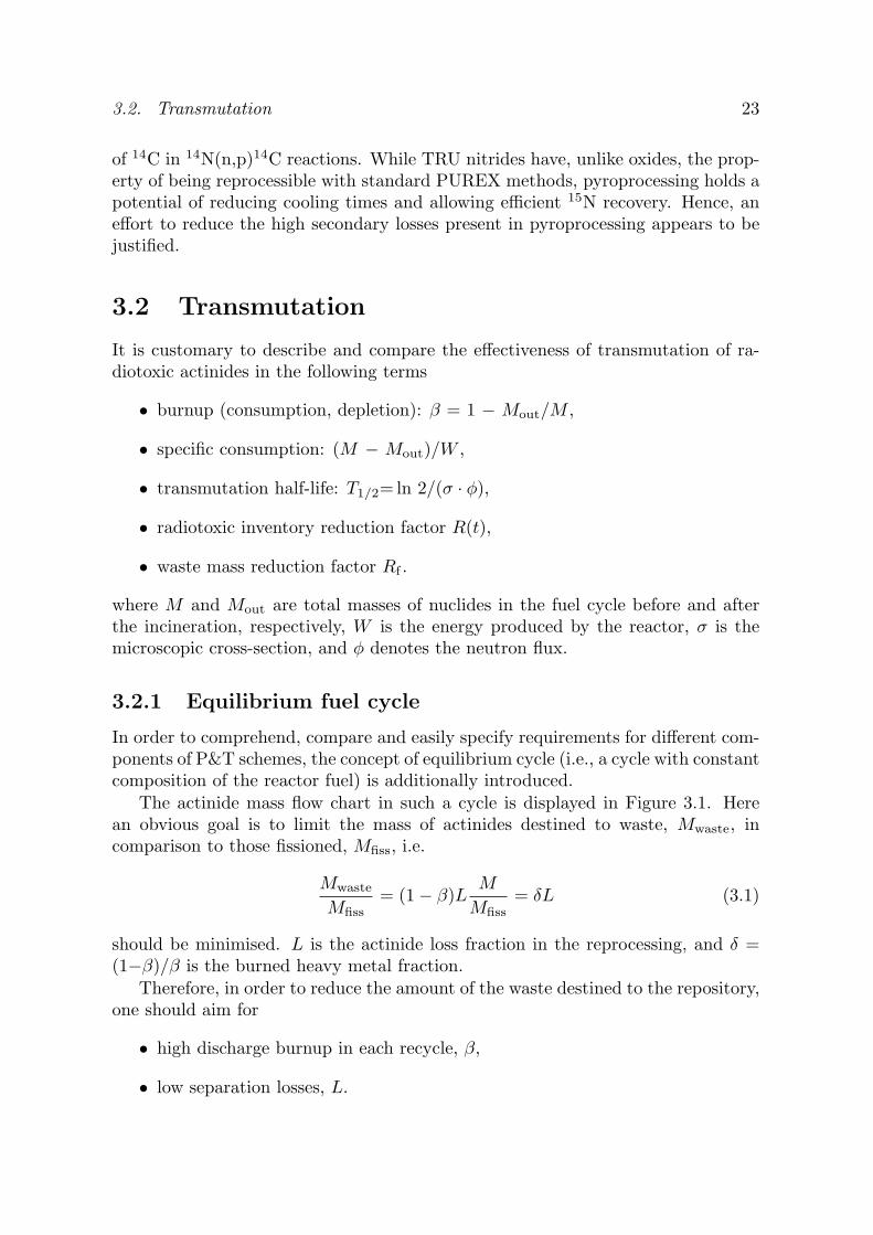
The actinide mass flow chart in such a cycle is displayed in Figure 3.1. Herean obvious goal is to limit the mass of actinides destined to waste, Mwaste, incomparison to those fissioned, Mfiss, i.e.
Mwaste
Mfiss= (1 − β)L
M
Mfiss= δL (3.1)
should be minimised. L is the actinide loss fraction in the reprocessing, and δ =(1−β)/β is the burned heavy metal fraction.
Therefore, in order to reduce the amount of the waste destined to the repository,one should aim for
• high discharge burnup in each recycle, β,
• low separation losses, L.
24 Chapter 3. Partitioning & Transmutation
Reprocessing
Reactor
H
Fuel
TRU/MA
Fission energy
supply
fabrication
M = Min + Mrec (1 - β) MMTRU
= f Min
Mfiss = β M
Mrec= (1 - β) (1 - L) M
Mwaste= (1 - β) M L
Fertile materialsupply
Mfert = (1- f) Min
M = Min
1 - (1- β)(1 - L)
In equilibrium:
Mfiss ≈ Min
Figure 3.1. Actinide mass flow chart in closed equilibrium fuel cycle.
The amount of the fuel which enters the equilibrium fuel cycle is Min, which includessupply of TRU/MA mixture, MTRU, and fertile/diluent matrix (238U, 232Th), Mfert.The fraction of the TRU/MA supply in the load/top-up fuel is then denoted as f .
The amount of fuel in the equilibrium cycle is a function of burnup level β andreprocessing losses L through
M =Min
1 − (1 − β)(1 − L)(3.2)
With the waste mass reduction factor in the fuel cycle defined as Rf = MTRU/Mwaste,the losses in the reprocessing are consequently
L ≈ f
δRf(3.3)
The radiotoxic inventory reduction factor compares the radiotoxic inventoryreduction in the equilibrium cycle to that of the top-up fuel
R(t) = Rneutr(t)Min
Mwaste=
Rneutr(t)δL
(3.4)
where Rneutr(t) is the neutronic toxicity reduction factor, depending on the corecharacteristics of the reactor and composition of its fuel. The factor Rneutr(t) isthe radiotoxic inventory for one mole of the feed over one mole of the equilibrium

3.2. Transmutation 25
inventory after a decay time t. Considering that a majority of the transuranics haveeffective ingestion coefficients eing
50 in the range of 10-26·10−8 Sv/Bq, we infer thatthe decisive contribution to the radiotoxic inventory reduction is from the wastemass reduction, determined in its turn by burnup level β and reprocessing lossesL. In more rigourous analyses, one has shown that the Rneutr(t)-factor is in theinterval 0.7-2.4 for most of the reactor systems [25]. Hence, the major contributionto the radiotoxic inventory reduction comes from the reduction of actinide mass.
We can therefore directly relate requirements which should be posed on thefuel burnup and recovery yields with respect to the desired radiotoxic inventoryreduction factor. Giving the example, we assume a fertile-free top-fuel (f = 1)reaching an average burnup of 15%FIMA. In order to attain desired reduction factorof 100 in the radiotoxic inventory of spent fuel, the separation losses have to beunder 0.18%. As higher burnups than 15-20%FIMA have not yet been proven, anactinide recovery yield of 99.9% is hence needed in order to accomplish an effectivetransmutation.
3.2.2 Net consumption
The main purpose of the transmutation reactors operating in radiotoxic inventoryreduction schemes is to achieve as high as possible net consumption of plutoniumand minor actinides. Therefore, in addition to the need for high burnup (and/orlow separation losses), the requirement is that
• the reactors’ own production of TRU should be minimised, i.e. amount of thefertile material is minimised, limiting TRU breeding (f ∼1),
• the fission fraction ratio of TRU inventory should be as high as possible, i.e.a fast neutron spectrum should be applied in order to take an advantage ofhigher fission-to-absorption ratios (see Figure 3.2); the cycle transmutationPu → Am → Cm → Pu is thus avoided with a positive effect on the neutroneconomy as explained in the next section.
However, removal of 238U together with an increase of mean neutron energyof the reactor system have adverse effects on several core safety parameters, par-ticularly Doppler effect and (effective) delayed neutron fraction. High fractions ofeven-neutron number (i.e., fertile) plutonium and minor actinide isotopes in thefuel further exacerbate coolant void reactivity. On the other hand, higher minoractinide content somewhat lowers the reactivity loss during burnup in the cycle,allowing to somewhat alleviate the economic penalties associated with higher fuelenrichments otherwise needed. The fuel composition, system’s spectrum, and fluxlevel influence the neutron balance in the system. The neutron economy of the TRUfuelled systems is, together with their safety parameters, thoroughly discussed inthe next two sections.

26 Chapter 3. Partitioning & Transmutation
0.01 0.1 0.5 1 2
0.01
0.1
1
Energy [MeV]
Fission probability
240Pu
242Pu241Am243Am238U
Figure 3.2. Fission probability of the actinide nuclides σf/σa as a function ofneutron energy.
3.2.3 Neutron economy
In order to assess the neutron economy of different types of fuels, and reactorsystems with different types of neutron spectra and magnitude of neutron flux, theneutron consumption parameter, D, was introduced for each nucleus in the fuel bySalvatores et al. [41]. The parameter D is defined as the number of neutrons neededto transform the nucleus and its reaction daughters into the required final state, i.e.,in the case of actinides, into the fission products. Negative neutron consumptionvalues mean that there is an excess of neutrons in the reactor systems supportingits neutronic needs (i.e. can be used for incineration of e.g. fission products), whileneutrons have to be supplied into the reactor if a nuclide with positive D shouldbe transmuted.
The values of D for 238U, plutonium, minor actinide, and TRU vector are givenin Table 3.1 for different model reactor systems.
We observe that a pure MA fuel cannot be transmuted in a thermal spectrum,due to the unfavourable neutron balance. However, the spectrum of thermal ADSis not a limiting factor for transmutation of plutonium. Thus, while the whole TRUvector can be incinerated in both thermal and fast spectrum, the fuel with highcontent of minor actinides is transmutable only in the fast spectrum. The issue ofcriticality or sub-criticality of the reactor is only the subject of consideration withrespect to deteriorated safety characteristics, which we mention in the next section.

3.2. Transmutation 27
Thermal FastTop-up fuel TRU ADS TRU ADS MA ADS FR238U +0.24 −0.64 −0.64 −0.85Pu −0.40 −1.34 −1.28 −1.53MA +0.37 −0.86 −0.79 −1.10TRU −0.30 −1.29 −1.23 −1.48
Table 3.1. Neutron consumption parameters for different equilibrium cores. Ther-mal ADS is a graphite-moderated molten salt reactor proposed by LANL [42], fastTRU ADS is a proposal of Pb/Bi-cooled core employing metallic fuel [43], MA ADSis a nitride Pb/Bi burner proposed by JAERI [44], and fast critical reactor (FR) is ofan ALMR-type. Pu and TRU vectors correspond to those of discharged LWR-UOXfuel with a burn-up of 50 MWd/tHM; MA vector is the mixture of minor actinidescoming from LWRs and FRs of the first stratum reactor park of the double-stratascenario, see Section 3.3.3. Table was adopted from OECD/NEA study [25].
3.2.4 Safety aspects
Inherent stability of a nuclear reactor, as any dynamic system, can be achievedonly by negative feedbacks acting sufficiently fast that the integrity of the reactorcore is not compromised. The feedback mechanisms operating in the nuclear re-actors typically constitute of an event chain where an increase in power or changein its distribution leads to decrease in reactivity through temperature dependentmicroscopic and/or macroscopic cross-sections.
In the sub-critical system, the requirements on the feedback mechanisms arepartially relaxed due to the inferred sub-criticality [38]. However, if a substantialreactivity could be introduced into the system, e.g. during coolant voiding, suchthat the power is significantly increased, absence of negative feedbacks could leadto core damage in spite of the system remaining sub-critical [45]. If a large sub-criticality margin would be required (keff ∼ 0.9) in order to prevent core damage, itwould introduce penalties on the total reactor power and discharge burnup. Thus,one might be required to optimise the core sub-criticality level, while, at the sametime, provide sufficiently strong negative temperature reactivity feedbacks. Thelatter could be also stipulated as an a priory requirement for successful licensingof any energy producing reactor.
3.2.5 Reactivity temperature coefficients
The total change in the reactivity of the system is given as a sum of
ρT = ρt + ρc + ρe (3.5)
where ρt is the reactivity due to the temperature changes in the reactor, ρc is thereactivity introduced by control rods or other absorbing materials as e.g. fissionproducts, and ρe is the external reactivity introduced from outside.

28 Chapter 3. Partitioning & Transmutation
In the case when no reactivity is introduced from external sources and absorbingmaterials, ρt determines the temperature stability of the reactor. The temperaturereactivity coefficients are then defined as the change in the reactivity upon temper-ature change of the i-th component of the reactor core
ai =∂ρ
∂Ti(3.6)
In a heterogeneous reactor, we usually recognise four distinctive geometrical com-ponents: fuel, structural material, moderator and/or coolant.
In the reactor core, the temperature reactivity feedback is mainly due to thefollowing physical events
• neutron spectrum shift affecting effective scattering and absorption cross-sections in the coolant (and moderator),
• widening of the resonance absorption cross-sections, changing the probabilityfor absorption reaction (Doppler effect),
• material density/phase change affecting macroscopic cross-sections,
• changes in the core dimensions due to thermal dilatation of materials (fuel,structure, cladding) and/or bending of the fuel elements.
Therefore, the reactivity changes as function of temperature can be decomposed as
dρ
dT= (
∂ρ
∂T)γ + (
∂ρ
∂γ)σ(
∂γ
∂T) (3.7)
where the (∂ρ/∂T )γ is the nuclear part of the reactivity coefficients (due to thechange of the nuclear properties of the material, i.e., cross-sections), and (∂ρ/∂γ)σ isthe density reactivity coefficient, describing the temperature changes as a responseto the change of the material density.
The total change of reactivity is then given by
ρT =∑
i
1Vi
∫ai(r)Ti(r)Ω(r) dr (3.8)
where Ω(r) is the weight/importance function describing the relative spatial influ-ence of the temperature on the reactivity, and Ti(r) is the temperature gradientcorresponding to the state at which ρT = 0.
It is important to note that apart from the changes of the reactivity inducedby the temperature, one can also have reactivity change due to longer long-termevents, such as swelling of cladding material or fuel pellet. Reactivity can be alsointroduced during a transient, e.g. if the fission gases are released from the pelletto the plenum.
Typical values of temperature coefficients for thermal and fast neutron coresare listed in Table 3.2. While all reactivity coefficients are negative in the thermal

3.2. Transmutation 29
Mechanism EBR Super BREST PWR106a [K] II
FermiPhenix 1200 UOX fuel
Axial fuel expansion −3.9 −2.5 N/A −0.8 ≈ 0Coolant density change −9.1 −7.1 +8.0 +3.4 −50 to −8Structure expansion −9.7 −6.0 −11.0 −7.7 ≈ 0Doppler coefficientat nominal temperature
N/A −2.0 −4.0 −5.4 −4 to −1
Table 3.2. Reactivity temperature coefficients for thermal and fast reactor cores [46,47, 48, 49]. Reactivity coefficients due to the density change of both coolant and sub-assembly material are quoted for EBR-II and Fermi.
reactor, in fast systems the total temperature reactivity coefficient is the sum of pos-itive and negative parts. Moreover, geometrical changes play more significant rolein fast spectrum systems than in thermal reactors, where the coolant/moderatortemperature coefficient has the major importance.
Prompt, inherent, and negative reactivity feedbacks are needed in order to mit-igate positive reactivity transients. Doppler temperature coefficient is a promptresponsive feedback to power changes as it is dominated by the nuclear componentinvolving the broadening of actinide absorption resonances. On the other hand,the coolant and moderator temperature coefficients are somewhat delayed allow-ing for heat to be distributed from fuel into the coolant. In the next sections, wewill treat coolant and fuel temperature reactivity coefficients together with delayedneutron fractions in more detail. The objective is to give as an important theoret-ical background before advancing into more elaborate studies of safety aspects oftransmutation reactors, which will be presented in Chapter 6.
3.2.6 Coolant temperature reactivity coefficient andvoid worth
The coolant temperature coefficient is not a characteristic of the coolant itselfbut a collective property of the core lattice and fuel design, fuel composition andcoolant/moderator type. In light-water reactors, the negative coolant/moderatorreactivity coefficient facilitates an important self-controlling mechanism of the sys-tem (core lattice is then so called undermoderated). Specifically, in BWR, anincrease in steam-to-water ratio leads to a decrease of the reactivity. However,sometimes, reactor cores exhibit positive coolant reactivity coefficients, e.g., D2Omoderated and cooled reactors (CANDU), or H2O cooled-graphite moderated reac-tors (RBMK). Operational stability of the reactor with positive coolant reactivitycoefficient is then ensured by the strong negative power reactivity coefficients. Ifthat is not present or is weak, one has to rely on actively operated reactor controlsystems rising serious safety concerns. At the same time, it is impossible to rely onnatural circulation in order to cope with the cooling accidents.

30 Chapter 3. Partitioning & Transmutation
Loss of coolant has two distinctive consequences on the reactor operation. First,the ability of the heat removal is lost leading to overheating and possibly also toloss of core integrity. The loss of heat removal capability was one of the mainreasons for core melting accidents, e.g. at the Three Mile Island nuclear reactorat Harrisburg, Pennsylvania. Second, it can introduce reactivity into the system.The coolant temperature reactivity is one of the most prominent characteristics offast reactors and some existing designs of liquid metal cooled reactors have coolanttemperature reactivity coefficient positive, e.g. Super Phenix reactor in France(see Table 3.2). The negative temperature reactivity feedback is then ensured bystrong contributions from expansion of grid structure and from fuel temperaturecoefficient.
The coolant density change or occurrence of the void in the core can be a resultof the following events
• temperature increase of the coolant due to pump failure, human errors, inade-quate instrumentation and prediction of hot-channel factors, crud deposition,and plugging of the coolant channels; ultimately, this leads to a coolant phasechange - boiling. Note that accident scenarios assuming coolant boiling areless relevant for systems cooled with lead-alloys due to the high boiling tem-perature of both Pb and Pb/Bi (Pb: Tb= 2023 K; Pb/Bi: Tb= 1943 K), whilein sodium cooled systems (Tb= 1156 K) coolant boiling can occur before anysignificant damage to the fuel, clad, or structural material would be inflicted.
• blocking of the coolant circulation as a consequence of coolant freezing in thesteam generator, i.e. overcooling.
Additionally, void cavities can appear in the core due to
• gas leakage from ruptured pins,
• steam ingress from ruptured steam generator,
• blow-down of bubbles from gas injection system,
• coolant leakage caused by brittle failure of the reactor vessel.
The coolant acts in the reactor not only as a neutron absorber, but also asmoderator, affecting the neutron spectra. The reactivity change when decreasingthe density of the coolant in fast neutron cores from coolant is mainly due to twoeffects
• spectral hardening, i.e. reduction of the neutron moderation, with a concur-rent increase of actinide fission probabilities,
• reduction of neutron parasitic absorption in fuel, coolant, and cladding.
3.2. Transmutation 31
ρ A N Tm TbCoolant [g·cm−3] [u] [10−22·cm−3] [K] [K] ξ
Na 0.847 22.99 2.22 371 1156 8.45·10−2
Pb/Bi 10.15 208.1 2.94 398 1943 9.59·10−3
Pb 10.48 207.1 3.05 601 2023 9.63·10−3
He 4.13·10−3 4.003 0.06 1.05 4.15 4.25·10−1
Table 3.3. Density (ρ), mass number (A), atomic density (N), melting (Tm)and boiling (Tb) temperatures, and average logarithmic decrement of energy (ξ)of coolants considered in the study. Coolant densities are given at 700 K, heliumpressure is 6 MPa [50].
3.2.7 Neutron slowing down
In this section we therefore analyse the neutronic (slowing-down) properties ofcandidate coolants for the fast reactor systems, see Table 3.3.
With an assumption that the neutron elastic scattering is isotropic in the centre-of-mass system (CMS), we can describe neutron slowing-down process in terms ofthe averaged logarithmic decrement of energy as
ξ = lnE1 − lnE2 = 1 +(A − 1)2
2Aln
A − 1A + 1
, A > 1 (3.9)
where A is the nuclide mass number and E1 and E2 are the energies before andafter the collision, respectively.
In order to apprehend the nature of the slowing-down process, the moderatingpower of the respective coolants is usually defined as
ξΣs = ΣiNiξiσi (3.10)
where Ni is the atomic density of the i-th nuclide and σi is its elastic scatteringcross-section. However, to include also slowing-down process from the inelasticscattering in the evaluation, the energy-loss cross-section should be studied. It isdefined as
Σ∆E ≡ Σel∆Eel + Σinel∆Einel
E, (3.11)
where∆Eel =
12(1 − α)En, α = (
A − 1A + 1
)2 (3.12)
and∆Einel = En − (
A
A + 1)2[En − Q
A + 1A
] (3.13)
is the average energy loss in elastic scattering and inelastic scattering, respectively;Q denotes the excited energy levels of the target nuclei, En is the neutron energy,and A is the target nucleus mass number (see Paper I).

32 Chapter 3. Partitioning & Transmutation
Energy-loss cross-section
[1/cm]
inelastic
elastic
Energy [MeV]
0.05 0.1 0.2 0.5 1 20.02
10-2
10-3
10-4
Figure 3.3. Energy-loss cross-section for 23Na. Data from JEF-2.2 library wereused. Macroscopic scattering cross-sections were taken at T = 600 K. According toPaper I.
Nuclide Abundance 1st 2nd 3rd
23Na 100% 459.1 2166 2495206Pb 24.1% 806.9 1171 1347207Pb 22.1% 572.5 902.1 1641208Pb 52.4% 2628 3213 3492209Bi 100% 900.6 1617 2455
Table 3.4. Threshold energies [keV] for inelastic scattering of liquid metal coolantsused in this study. 206Pb features additional five excited energy levels yieldingthreshold energies below or close to 2 MeV limit: 1474, 1692, 1713, 1793, and2008 keV. Table adapted from Paper I.
Threshold energies for the inelastic scattering (i.e., kinetic energies of the neu-tron in the laboratory system, En) are higher than excited level energies Q of thesystem. Considering the kinematics of the inelastic scattering
En,CMS + EN,CMS + Q =A
A + 1En (3.14)
where En,CMS + EN,CMS ≥ 0 (3.15)
we obtain a requirement for the laboratory kinetic energy of the neutron, En ≥A+1
A Q. En,CMS and EN,CMS are kinetic energies of the neutron and the nucleus inthe centre-of-mass system, respectively.

3.2. Transmutation 33
2
Energy-loss cross-section
[1/cm]
inelastic
elastic
Energy [MeV]
0.05 0.1 0.2 0.5 10.02
10-2
10-3
10-4
Figure 3.4. Energy-loss cross-section for natural lead. Cross-section data weretaken from ENDFB/VI-8 cross-section library. Σel and Σinel at T = 600 K wereused. Figure adopted from Paper I.
The energy-loss cross-section for sodium decomposed into the contributions fromelastic and inelastic scattering is displayed in Figure 3.3. The same comparison fornatural lead is made in Figure 3.4. In the whole energy range investigated (100 keV- 2 MeV), lead energy-loss cross-section due to the elastic scattering is significantlysmaller than for sodium. However, due to the presence of several thresholds forinelastic scattering in the energy interval from 0.57 to 2 MeV, the energy loss ininelastic scattering is notably larger than for sodium. Therefore, neutron spectrumof lead and lead/bismuth cooled reactors will be somewhat suppressed for energiesabove 1 MeV. On the other hand, the magnitude of neutron flux for sodium-cooledreactor is suppressed in the energy interval of 0.7-1.5 MeV, where contributions tothe neutron slowing down from elastic and inelastic scattering reactions are merelyequal, see Figure 3.5.
Additionally, the neutron mean free path, (λ=1/Σt), in sodium is larger thanthat of Pb/Bi. Therefore, the leakage of neutrons and their contribution to overallneutron balance in the system is more significant for Na. Further, higher scatteringin Pb/Bi without increasing the moderation for neutrons below 0.5 MeV wouldprevent the neutrons from escaping from the internal parts of the Pb/Bi-cooled coresand, at the same time, provide an excellent reflecting capability for the neutronswhich escape the system, see Figure 3.6. Hence, we can also infer that the neutroneconomy of the Pb/Bi systems would be better than for Na-cooled counterpartsand a smaller actinide fraction would be required for Pb/Bi than Na to reach

34 Chapter 3. Partitioning & Transmutation
0.5
1
1.5
2
Energy [MeV]
0.1 0.3 1 2
Flux ratio φPbBi / φNa
0.5
Figure 3.5. Neutron spectrum of the Pb/Bi-cooled system in comparison to theNa-cooled reactor having the same fuel and geometry design parameters. Redrawnfrom Paper I.
0.01 0.1
1
10
100
Microscopic scattering
cross-section
[barn]
Na, elastic
Pb(nat), elastic
Na, inelastic
Pb(nat), inelastic
Energy [MeV]
101
Figure 3.6. Elastic and inelastic scattering cross-sections for Na and Pb. Datawere taken from JEF-2.2 library.

3.2. Transmutation 35
criticality/same sub-criticality. On the other hand, e.g. power peaking issues aremore relaxed in sodium system as neutrons more easily escape the high reactivityregions. We develop on the subject in Chapter 6.
3.2.8 Feedback through material dilatation
A temperature rise causes expansion of core materials with concomitant changesin geometry. This influences the macroscopic cross-section (N · σ), affecting theinteraction rates (N · σ · φ), neutron mean free path, resonance self-shielding effectin the fuel, neutron leakage probability, and consequently changes overall criticalityof the system. Moreover, the material dilatation can alter the relative position ofcore parts, individual fuel pins or whole sub-assemblies. E.g. fuel sub-assemblybowing was the initiator of the accident at the experimental breeder reactor EBR-1Mark II in November 1955. The subsequent analysis of the core have shown thatthe transient had resulted in melting of 40%-50% of the fuel elements.
Temperature changes causes a dilatation of all materials in the core. However,the most important reactivity contribution with respect to the geometrical changesappear to be
• axial expansion of fuel column,
• radial expansion of the core lattice grid, changing spacing in-between fuelelements and effective radius of the core,
• thermal bowing of sub-assemblies.
Change in length of the i-th core component per change in temperature is givenby the linear expansion coefficient defined as
αi =1l0
dl
dT i(3.16)
where dl is the change in length, l0 is the initial length of the material, and dT isthe change in temperature. The density of the material then changes as
ρ =ρ0
1 + β∆T(3.17)
where β is the volumetric expansion coefficient (β ≈ 3α), ρ0 is the initial materialdensity, and ∆T = T − T0 is the temperature difference.
The linear expansion coefficient is usually itself dependent on the temperatureand for actinide nitrides and relevant diluent matrices, ZrN and HfN, it slightlyincreases with temperature, see Figure 3.7. For comparison, the linear expansioncoefficients of uranium, plutonium, uranium dioxide, and structural material aregiven in Table 3.5. For the mixture of the nuclides, the linear expansion coefficientis obtained by using Vegard’s law.

36 Chapter 3. Partitioning & Transmutation
500 1000 1500 2000 2500
4
6
8
10
12
14Linear expansion coefficient
α [10-6K
-1]
Temperature [K]
AnN
ZrN
HfN
Figure 3.7. Linear expansion coefficient of AnN [51], ZrN [51], and HfN [52] as afunction of temperature.
αMaterial [10−6·K−1] Note
U 13.9 (α) 300 KPu 55 (α), 35 (β) 300 KUO2 11.1 to 13 700−1600 KAnN 8.5 to 11.8 600−2500 KSS-316 18.6 to 21.6 300−1300 K
Table 3.5. Linear expansion coefficients of some core materials [53, 32, 50].
The dilatation of the material in the core affects neutron mean free path, whichis increased as λ = 1/Σt = 1/(N · σt). At the same time, the core dimensionsincrease and the densities of the material in the core decrease, which has positiveand negative effect on the system reactivity, respectively.
Increase in the core dimensions, assuming the cylindrical core, decreases theneutron leakage probability as surface-to-volume ratio becomes smaller with largerR and/or H
2πr(r + H)πr2H
= 2(1H
+1r) (3.18)

3.2. Transmutation 37
where r and H are the radius and the height of the core, respectively. In the caseof the axial expansion of the fuel column, the density of the fuel changes as
∆ρ
ρ0≈ −∆l
l(3.19)
while in the case of the radial displacement of the core grid the density varies withthe square of the core radius
∆ρ
ρ0≈ r2
0 − (r0 + ∆r)2
r2≈ −2∆r
r(3.20)
Thus, the reactivity change upon the core expansion is actually the result of twocomponents, a positive one due to the core expansion, and a negative one due tosmaller densities. In fast reactors, the former effect is usually smaller than thelatter, yielding the negative overall expansion coefficient [54]. We also expect thatan increase in the core radius is approximately twice as effective in reducing thereactivity than the axial fuel expansion.
3.2.9 Doppler feedback
The Doppler effect involves changes of reactivity due to variation of fuel temper-ature. This effect has a premium significance in nuclear reactor safety, providingimmediate reactivity feedback, which responds to the changes in the fuel tempera-ture. In fact, the absorption cross-section of an actinide is dependent on the relativevelocity between the nuclide and neutron. While the area under the resonance in-tegral [55]
Ires =∫ E0
E
σa(E′)dE′
E′ (3.21)
remains constant upon temperature changes, the effective resonance integral is thendependent on temperature through Σa in the denominator
Ireseff =
∫ E0
E
σa(E′)Σs
Σs + Σa
dE′
E′ (3.22)
The probability of neutrons escaping the resonance capture then changes as
p = exp(− N
ξΣsIreseff ). (3.23)
The fuel temperature reactivity coefficient can be approximated for most reactordesigns by a 1/Ta-dependence (a∼1 for oxide-fuelled sodium-cooled fast reactors)and thus the Doppler effect is often in the literature quantified in terms of theDoppler constant

38 Chapter 3. Partitioning & Transmutation
105
103
101
10-1
1 10
Energy [eV]
100
Capture cross-section
of238
U [barn]Capture cross-section
of232
Th [barn]
1 10
Energy [eV]
100
105
103
101
10-1
Figure 3.8. The neutron capture cross-section for 238U and 232Th. JEF-2.2 datawere used.
Capture cross-section
of 240Pu [barn]
1 10
Energy [eV]
100
105
103
101
10-1
Capture cross-section
of 241Am [barn]
1 10
Energy [eV]
100
105
103
101
10-1
Figure 3.9. The neutron capture cross-section for 240Pu and 241Am. Data weretaken from JEF-2.2. Note large 240Pu resonance at ∼1 eV.
KD = Tdk
dT(3.24)
The Doppler effect itself is prominent in an energy range of well-separated reso-nances around 1 keV (higher energies cross-section variations with temperature areminimal) and for fertile nuclei it results in a decrease of resonance escape probabil-ity [46]. As shown experimentally, mainly fertile materials as 238U, 232Th, and to aminor extent 240Pu, contribute to the Doppler effect, see also Figures 3.8 and 3.9.On the other hand, the Doppler effect of most of the fissile isotopes as 239Pu and235U appear to be almost zero or even positive [54]. In the thermal spectrum, plu-tonium fuel can provide positive Doppler feedback due to the huge 0.3 eV resonanceof 239Pu.

3.2. Transmutation 39
In the standard FBR design, the major contribution to the negative Dopplereffect comes from broadening of 238U resonances. In hard neutron spectra, onlysmall portion of neutrons is moderated down to the region of pronounced resonances(below 100 eV), where the contribution to the Doppler effect is the most profound.At the same time, as uranium content is significantly reduced in transmutationreactors, the Doppler coefficient becomes small. Extensive studies of propertiesof different fuel carrier material which would help to at least partially regain theDoppler effect were reported e.g. by Lombardi [56] and Conti [57]. It appearedthat a certain degree of Doppler could be obtained using materials with significantresonances in the fast energy range - W, Mo, Nb - which, on the other hand, exhibitadverse effect on coolant void worth.
3.2.10 Delayed neutron fractions
The deterioration of kinetic parameters as delayed neutron fraction β and neutronlifetime also imposes constraints on transient behaviour of reactor systems. Thedelayed neutron fractions are specific characteristics of individual nuclei determinedby their distribution of fission yields. In Table 3.6, the values of total delayedneutron yields νd and average number of neutrons per fission νtherm are listedtogether with estimated delayed neutron fractions.
Two regularities can be observed from listed data: the total delayed neutronyield increases with the atomic mass of a given element but, on the other hand,decreases with increasing proton number. Furthermore, the delayed neutron yieldsremain energy independent until 4 MeV when they quickly drop by about a factor oftwo. For a fast neutron spectrum, the average neutron yields are slightly increasedresulting in a further reduction of delayed neutron fractions.
The effective delayed neutron fraction, βeff , is the number of delayed neutronsinducing fission in the system Nd,i compared to number of all neutrons inducingfission in the reactor Ni. The most rigourous mathematical definition of βeff wasgiven by Keepin [58] as
βeff =∫
Ψ(r, E′, Ω′)χd(E′)νd(E′)Σf(r, E, Ω)φ(r, E, Ω)dEdΩdE′dΩ′dr∫Ψ(r, E′, Ω′)χ(E′)ν(E′)Σf(r, E, Ω)φ(r, E, Ω)dEdΩdE′dΩ′dr
(3.25)
where φ is the neutron flux at position r with energy E and solid angle Ω, ν isthe averaged neutron yield per fission, νd is the averaged delayed neutron yield,Σf is the macroscopic fission cross-section, χd, χ is the energy spectrum functionof delayed and all neutrons in the system, respectively, and Ψ(r, E, Ω) is the neu-tron importance function (i.e. function proportional to the asymptotic power levelresulting from introduction of a neutron into the critical system). In sub-criticalsystems, Ψ(r, E′,Ω′) is proportional to the probability of neutron to induce fission.
In Monte Carlo code MCNP [59], β and βeff are not given explicitly. Moreover,Nd,i and Ni cannot be obtained directly. We therefore write
βeff =Nd,i
Ni=
Pd,i
Pi
Nd
N=
Pd,i
Piβ (3.26)
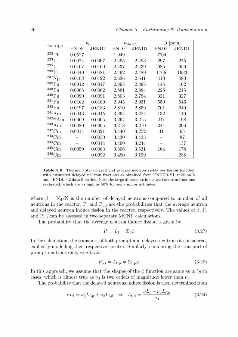
40 Chapter 3. Partitioning & Transmutation
νd νtherm β [pcm]IsotopeENDF JENDL ENDF JENDL ENDF JENDL
232Th 0.0527 – 1.949 – 2704 –233U 0.0074 0.0067 2.495 2.493 297 275235U 0.0167 0.0160 2.437 2.439 685 656238U 0.0440 0.0481 2.492 2.489 1766 1933237Np 0.0108 0.0122 2.636 2.541 410 480238Pu 0.0042 0.0047 2.895 2.895 145 162239Pu 0.0065 0.0062 2.881 2.884 226 215240Pu 0.0090 0.0091 2.803 2.784 321 327241Pu 0.0162 0.0160 2.945 2.931 550 546242Pu 0.0197 0.0183 2.810 2.859 701 640241Am 0.0043 0.0045 3.264 3.224 132 140242mAm 0.0069 0.0065 3.264 3.275 211 198243Am 0.0080 0.0095 3.273 3.210 244 296242Cm 0.0014 0.0021 3.440 3.252 41 65243Cm – 0.0030 3.430 3.433 – 87244Cm – 0.0044 3.460 3.244 – 137245Cm 0.0059 0.0063 3.606 3.531 164 178246Cm – 0.0092 3.480 3.199 – 288
Table 3.6. Thermal total delayed and average neutron yields per fission togetherwith estimated delayed neutron fractions as obtained from ENDFB-VI, revision 5and JENDL 3.2 data libraries. Note the large differences in delayed neutron fractionsevaluated, which are as high as 50% for some minor actinides.
where β = Nd/N is the number of delayed neutrons compared to number of allneutrons in the reactor, Pi and Pd,i are the probabilities that the average neutronand delayed neutron induce fission in the reactor, respectively. The values of β, Pi
and Pd,i can be assessed in two separate MCNP calculations.The probability that the average neutron induce fission is given by
Pi = Lf = Σfφ (3.27)
In the calculation, the transport of both prompt and delayed neutrons is considered,explicitly modelling their respective spectra. Similarly, simulating the transport ofprompt neutrons only, we obtain
Pp,i = Lf,p = Σf,pφ (3.28)
In this approach, we assume that the shapes of the φ function are same as in bothcases, which is almost true as νd is two orders of magnitude lower than ν.
The probability that the delayed neutrons induce fission is then determined from
νLf = νpLf,p + νdLf,d ⇒ Lf,d =νLf − νpLf,p
νd(3.29)

3.3. Transmutation strategies 41
Assembly Experimental JEFF-3.0 ENDF/B-VI JENDL-3.3values [pcm] β βeff β βeff β βeff
Godiva 659 ± 10 600 683 633 662 627 635Jezebel 194 ± 10 191 189 187 176 189 181242Pu – 565 – 594 247 545 183
Table 3.7. Effective delayed neutron fractions for Godiva, Jezebel and 242Pu criticalconfigurations. Note that the delayed neutron energy distribution for 242Pu is notgiven in JEFF-3.0. Experimental values were taken from ref. [60].
where νp is the prompt neutron yield.In order to test the reliability of the devised approach, the βeff was calculated
for two benchmark configurations, Godiva and Jezebel. Godiva is an unreflectedsphere of the highly enriched metallic uranium (234U 1.02 wt%, 235U 93.71 wt%,238U 5.27 wt%, radius 8.7414 cm, density 18.74 g/cm3), Jezebel is the similar sphereconfiguration with weapon grade plutonium (239Pu 95.2 at%, 240Pu 4.5 at%, 241Pu0.3 at%) enclosed in a thin nickel shell. A critical metallic 242Pu sphere was alsomodelled. Rather good agreement with the experimental values was obtained, seeTable 3.7.
3.3 Transmutation strategies
After defining incentives for P&T of spent nuclear fuel and identifying the basicphysical characteristics and constraints which accompany this process, we now givea comprehensive overview of different P&T schemes, involving both thermal andfast nuclear reactors. Most recently, the subject was studied by OECD/NEA [25].
In general, transmutation of transuranics are envisioned to be accomplished ineither so called homogeneous mode, where TRU nuclei are homogeneously dispersedin the whole reactor core, or heterogeneous mode, where the irradiation takes placein dedicated target sub-assemblies or in dedicated reactors operating exclusivelyTRU fuel.
Transmutation scenarios are considered to be either “once-through”, i.e. irradi-ation takes place until a significant depletion is reached and fuel/targets are directlydisposed of, or with multi-recycling when fuel/dedicated targets are discharged fromthe reactor, reprocessed and again returned to the transmutation process.
In a broad perspective, the different fuel cycle concepts investigated can becategorised as follows
• once-through fuel cycle, without spent fuel recycling, entailing the direct dis-posal of spent fuel in a geological repository; this strategy is applied in coun-tries without recycling possibilities or with proliferation concerns,

42 Chapter 3. Partitioning & Transmutation
• plutonium burning strategy, where plutonium is first incinerated in light waterreactors, and afterwards in critical fast reactors; minor actinides and fissionproducts are concurrently destined into the geological repository,
• closed fuel cycle which, in addition to the preceding scheme, involves burningof MA homogeneously distributed in FRs (BREST [48], EFR [61], IFR [62])or in dedicated reactor systems, e.g. ADS; such complete recycling entailsthat secondary waste streams to the repository are limited.
Variations of these basic principle schemes are displayed in Figure 3.10 and willbe discussed in detail below. From the system point of view, P&T is proposedto be achieved in two different scenarios: an evolutionary, with reactor systemsand reprocessing technologies of the present knowledge (aqueous), and innovative,where pyrochemistry technologies and advanced reactor systems are used for TRUburning in the closed fuel cycle.
The different fuel cycle/transmutation strategies will be discussed in the nextsections with respect to the reactor spectrum. In order to address the safety issuesassociated with introduction of minor actinides into the fuel, dedicated reactorsystems operating in both critical and sub-critical mode have been proposed. Wewill treat these systems in more technological detail in Chapter 4.
3.3.1 Thermal reactors
Thermal neutron spectrum systems encompass both commercial light-water re-actors (LWR), i.e., pressurised water reactors (PWR) and boiling water reactors(BWR), and heavy water CANDU type reactors.
Plutonium
The transmutation of Pu from spent LWR-UOX fuel is industrially accomplishedin light-water reactors in the form of so called mixed-oxide fuel (MOX). It involvesextraction of plutonium and uranium from spent fuel and re-use of plutonium mixedwith uranium tailings (235U enrichment of about 0.25%-0.3%) in fabrication of newfuel sub-assemblies. Plutonium reprocessed from about five to eight UOX spent fuelsub-assemblies having a burnup of 40 GWd/tHM is sufficient to produce one MOXsub-assembly with 5% to 8.2% Pu content. Reprocessed uranium has so far beenapplied in some test MOX sub-assemblies, but its use has not become an industrialpraxis also because of the large stocks of depleted uranium (about 7 tonnes isproduced per each tonne of enriched uranium). Its usage is also unfavourable dueto the presence of a neutron poison (236U), and because of its increased radioactivitydue to the strong γ-emitters 208Tl and 228Th, daughter products of 232U (half-life70 year).
The plutonium fission fraction ratio in the first MOX recycle is only about 25%while additional 10% is transformed into minor actinides [10]. The latter figurehighlights the major drawback of plutonium recycling in LWRs, which is the build

3.3. Transmutation strategies 43
up of minor actinides, as even neutron number nuclei have virtually zero fission-to-capture probability ratios in the thermal spectrum. Thus, despite the Pu massreduction, radiotoxic inventory actually increases.
Indeed, further mass reduction can be achieved by multiple recycling of pluto-nium. This is, however, accompanied with constraints on core neutronic behaviourand limitation at reprocessing plants as plutonium quality decreases. The qualityis defined as a mass fraction of fissile isotopes in the Pu-vector
QPu = 100 · m(239Pu) + m(241Pu)m(Putot)
. (3.30)
It diminishes in subsequent generations and drops from the value of about 70 forLWR Pu discharge down to about 45 at the fifth recycle generation in standardlattices of LWRs [63]. Due to the lowered plutonium reactivity, its enrichment inthe U/Pu mixture has to be increased in further generations which influences severalsafety characteristics of the reactor - particularly moderator void and temperaturereactivity coefficients, the Doppler coefficient and boron reactivity worth. This isdue to a spectrum hardening in MOX sub-assemblies which is further pronounced,e.g. in the case of loss-of-coolant accident, when fast fission of fertile Pu isotopesbecome significant. In order to keep the boron reactivity worth on the same limit,the concentration of the boric acid in the water has to be increased, which howeverfurther deteriorate coolant void reactivity. Thus, due to the positive void worth,the plutonium content in standard PWR lattice MOX sub-assemblies cannot exceed12 wt% [64].
These safety drawbacks may be mitigated by changes of sub-assembly latticedesign in order to achieve satisfactory spectrum thermalisation. This is accom-plished either by an increase of moderator/fuel ratio (up to 3.5 - 4) - so called highmoderation PWR (HM-PWR) [65], or by a radical decrease of the fuel smear den-sity from 9 g·cm−3 to 3.5 g·cm−3 keeping the same lattice geometry [66]. Anotherinnovative method was presented by CEA, proposing heterogeneous distribution ofuranium and plutonium pins in a fuel sub-assembly (Advanced Plutonium Assem-bly - APA and CORAIL MOX sub-assemblies) allowing to keep also an acceptablepower shape [67, 68, 69, 70]. A further possibility to mitigate void problems is toincrease the 235U fraction in the fuel keeping plutonium content fixed at 4% (socalled MIX approach) which on the other hand result in higher fabrication costs andlower Pu fission fraction ratios [71]. Combining the previous design approaches, anover-moderated 235U-enriched MOX sub-assembly (MOX-UE) was recently devel-oped [72]. In the S/A lattice with slightly increased moderation ratio, the neutronspectrum is sufficiently thermalised such that reasonable value of the void reactivityis maintained also during Pu recycling. In order to compensate for a degradationof the Pu vector (and respect 12% Pu limit), 235U enrichment in the fuel has to begradually increased (to 3% after 7 recyclings).
An additional major problem with high plutonium content fuels is the smalldelayed neutron fraction, which entails faster reactor response on reactivity and
44 Chapter 3. Partitioning & Transmutation
power transients. In this respect, the potential of LWRs to recycle stocks of weapongrade Pu (95% 239Pu, 5% 240Pu) seems to be questionable.
Safety of reactor cores is proven up to 30%-50% of MOX fuel assemblies withplutonium enrichment up to 5%. At this level as much plutonium is consumed inMOX sub-assemblies as is produced in UOX. For MOX-UE, stabilising Pu inven-tory requires that 25-28% of the energy is generated in the MOX sub-assemblies.Maximum plutonium consumption in LWRs would be reached in 100% MOX cores,whose feasibility, however, needs to be further investigated.
Obviously, due to the presence of uranium in the U/Pu matrix, plutonium de-pletion is somewhat diminished. Use of an inert matrix instead of uranium couldgain higher plutonium consumption, which is, however, at the expense of fuel tem-perature feedback. Some studies have been also done on the use of thorium as aplutonium support in MOX fuel showing improved void characteristics [73, 74].
Nevertheless, recycling of plutonium in LWR does not meet our objectives forP&T technologies as it does not significantly reduce the radiotoxic inventory ofspent fuel. The amount of minor actinides produced in a MOX sub-assembly is 3-4times higher than in corresponding UOX sub-assemblies having increased require-ments on interim storage and short-term repository performance as consequence.
Minor actinides
Possible transmutation strategies for minor actinides are with certain limitationsdetermined by the performance and abilities of chemical separation processes. Thegeneral problems accompanying addition of minor actinides to the fuel are similar tothose already mentioned for plutonium - deterioration of physical characteristics ofreactor cores, particularly coolant void temperature coefficient, Doppler feedback,and delayed neutron fractions. An additional serious difficulty is the helium produc-tion due to α-decaying 242Cm, 244Cm, and 238Pu which enhances fuel swelling andresults in pin over-pressurisation. Thus the content of minor actinides in reactorcores has to be somewhat limited.
Americium and curium Transmutation of both americium and curium has tobe accomplished if a reduction of radiotoxic inventories higher than a factor of 100is to be reached [75, 25]. Moreover, incineration of pure curium in a standalonefacility can not be considered due to the very high heat production from the αand neutron emitters 242Cm and 244Cm. The only remedy is either its incinerationtogether with americium or transmutation of curium as 240Pu allowing for a decayof 244Cm (half-life 18.1 yr) in a time period of 100 years or so, which still leaves245Cm untransmuted.
Studies of the homogeneous recycling of americium show a significant dete-rioration of the coolant void reactivity coefficient. Taking into account limits onuranium enrichment (< 5%) or plutonium content (less than about 12%) in the caseof MOX fuels, the maximum concentrations of americium in fuel were identified as1% for standard PWR and 2% for highly moderated lattices [21]. It results in a

3.3. Transmutation strategies 45
10% decrease of Doppler coefficient while the moderator temperature coefficient isdiminished by 25%. The specific consumption of americium in UOX fuel (total in-ventory of about 1.1 tonne) reaches about 19 kg/TWhe (annual production of aboutfive 1000 MWe-LWRs). Adding 1% Am into MOX-UE sub-assembly requires that235U enrichment is increased by about 2% and Pu content decreased to ∼8%. Ifboth plutonium and americium inventory should be stabilised, 40% MOX-UE coreshave to be applied [72]. As the fission-to-absorption ratio for 241Am is very low(virtually zero) in thermal spectra, most of the americium (70%) is converted via242Am into 242Cm which consequently α-decays into 238Pu, resulting in increasedfuel swelling rates due to the formation of He bubbles.
Targets A much more attractive option with respect to core neutronic charac-teristics was thought to be heterogeneous americium recycling in separate sub-assemblies placed at the core periphery, thus having lower influence on core char-acteristics. As thermophysical properties of AmO2 are not favourable owing to thelow thermal conductivity and melting temperature, several materials have been in-vestigated as suitable matrices for americium incineration. E.g., the EFTTRA-T4experiments [76] study behaviour of americium incorporated in spinel (MgAl2O4)matrix (11 wt% of Am) during irradiation in Petten’s thermal high flux reactor.Another compound - MgO-AmO2−x - was fabricated and irradiated by ITU [77],having americium particles homogeneously dispersed in the matrix as well as in themacroscopic solution with it.
Due to anticipated significant difficulties with reprocessing of such target fuels,a once-through transmutation scheme is envisaged for thermal americium incinera-tion. Dedicated americium targets are left in the reactor until a significant depletiontakes place and are thereafter directly disposed of. The residence time of such as-semblies in the reactor is limited by the maximum radiation damage which inertmatrix and cladding can withstand and by the maximum capacity of the targetpins to accommodate produced helium.
As the preliminary calculations show, consumption of americium in dedicatedtargets is rather low, reaching about 9 kg/TWhe in the best case (depletion 74%)having 30 wt% AmO2 in a mixture with an inert matrix. This corresponds to halfthe annual LWR americium production (4 years after decay). Furthermore, due tothe low reaction rates, the equilibrium incineration of americium in LWRs impliesvery large fuel inventories - about several hundreds of tons of TRU - much morethan waste discharges.
Indeed, the radiotoxic inventory is again increased due to the massive curiumproduction which, together with reactivity and swelling problems, makes LWRs un-suitable for effective MA incineration in a P&T scheme. The fuel swelling problemsare only partially relaxed in the fast neutron spectra and need to be addressed indedicated systems with favourable minor actinide fission-to-absorption ratios andwhere gasses may be released into the plena, which is not possible in standardLWRs.

46 Chapter 3. Partitioning & Transmutation
Fission products
As discussed in Chapter 2, there are some long-lived fission products (LLFP),which contribute to the long-term geosphere dose, also when considering a humanintrusion scenario into the repository. These are hence candidates for partition-ing and transmutation schemes - 129I (production rate 5 kg/GWe ·year), 135Cs(12 kg/GWe·year), and in an oxidising environment 99Tc (21 kg/GWe·year).
The transmutation of fission products is considered to be accomplished in het-erogeneous mode fixing individual LLFP nuclides in suitable target forms. Thetarget material/matrix has to be stable upon irradiation and withstand high bur-nups, the melting point has to be high and compatibility with cladding and coolantmust be ensured. Transmutation of selected fission products can be accomplishedby single neutron capture, resulting in stable nuclei
99Tc + n →100 Ru + β− + νe (3.31)
and129I + n →130 Xe + β− + νe (3.32)
The superiority of transmutation of these isotopes is that even further double neu-tron capture would lead to stable nuclei (101Ru, 102Ru, 131Xe, 132Xe). The cross-section for neutron capture is highest at thermal energies with significant reso-nances in the epithermal region. It is therefore attractive to place LLFP pins inthe moderator of thermal reactors. On the other hand, as high fluxes as possibleare favourable, which would suggest the placement of LLFP into the specially mod-erated sub-assemblies of fast reactors. A major drawback of a such approach is astrong self-shielding causing dips in neutron flux at the centre of LLFP pins and,as we will show, the fast neutron induced LLFP transmutation performs at leastequally well (see Paper III).
The transmutation of long-lived fission products has been studied in the frameof the EFTTRA collaboration since 1992 [76].
In the case of 99Tc, the metallic form was chosen as the most attractive optiondue to the highest technetium concentration and compatibility with transmutationproduct (100Ru). The irradiation of sample targets has been done in thermal po-sitions of Petten’s high flux reactor reaching burnups from 6% to 16% [78, 79].Neither swelling nor microstructural changes in the pellets have been observed andit seems that metallic technetium is a good candidate for transmutation. However,its behaviour in fast reactor environments remains to be confirmed. Theoreticalpredictions of transmutation half-lifes are from 15 to 18 years in fast reactors and40 to 77 years in LWRs. Due to the limitations posed by radiation damage ofcladding materials, the transmutation has to be accomplished in multi-recyclingmode in order to achieve a significant reduction of Tc content.
The choice of target material is more complex for iodine. 129I mass proportionis about 80% in a mixture with stable 127I which seems to be rather affable. Inelemental form, iodine is rather volatile (melting point 387 K) and thus some bi-nary compounds seem to be more suitable - CeI3, PbI2, and NaI. The irradiation

3.3. Transmutation strategies 47
experiments in Petten HFR have revealed incompatibility of PbI2 with the 15-15Tistainless steel capsule, which corroded. At the same time, serious difficulties havebeen encountered while manufacturing CeI3 and thus NaI seems to be so far thebest candidate for iodine incineration. Another important question, limiting io-dine transmutation rate, is the accommodation of gaseous 130Xe, which has to beaccomplished either by a large gas plenum in the LLFP pin or by special venteddesign.
In the case of cesium, isotopic separation of 133Cs, 135Cs, and 137Cs has to be ac-complished prior to incineration, which makes transmutation of 135Cs economicallyhardly feasible.
3.3.2 Fast reactors
Plutonium
The development of a self-sustaining U-Pu fuel cycle based on MOX fuelled fastbreeder reactors engaged thousands of nuclear scientists during the 60s and 70s.The technical complexity and associated difficulties have together with economicaldisadvantages (cheap uranium) and political reasons considerably slowed down theirintroduction into the nuclear reactor parks. Furthermore, in terms of partitioningand transmutation technologies, the incentives for fast reactor deployment changesand are shifting from plutonium/transuranic breeding to burning.
While incineration of plutonium in thermal neutron spectra is limited due tothe deterioration of plutonium vector composition and core neutronic and safetyaspects, and the limitation in the PUREX reprocessing technologies, the infinitemultiple-recycling of plutonium in fast reactors is theoretically feasible [73]. Thesuperiority of fast spectrum in actinide transmutation and radiotoxic inventoryreduction of spent fuel is recognised by most authors [39, 80, 81]. All actinideisotopes are in principle fissionable and in a high flux neutron spectrum of fastreactors act as neutron producers, see also Section 3.2.3 [41, 82].
Special type of fast burner reactors (FBuR) without breeding blanket and thuswith maximised plutonium consumption are extensively studied. The CAPRAreactor [83] was proposed in 1992 utilising MOX fuel with up to 45% of plutoniumenrichment. The CAPRA core can work in symbiosis with about one MOX-LWRand five UOX-LWRs achieving significant reduction of the Pu inventory as onlyreprocessing losses are treated as a waste. However, due to the massive productionof minor actinides, the radiotoxic inventory is reduced only by a factor of three forseveral thousand years and by five-six afterwards. The plutonium depletion reaches55% and its concentration in spent CAPRA fuel is reduced to 25% which is themaximum concentration in MOX fuel being compatible with the PUREX process.Obviously, this difficulty could be solved by applying other types of fuel matricesas nitrides or metallic fuels together with pyro-reprocessing.

48 Chapter 3. Partitioning & Transmutation
Minor actinides
The neutron surplus when transmuting minor actinides is positive in fast spectrumfor fluxes over 1015n·cm−2s−1 [41]. MA incineration is again envisioned in homoge-neous and heterogeneous modes considering either a once-through or multi-recyclingscheme.
Neptunium As in the case of LWRs, the homogeneous introduction of neptuniumin the MOX fuel is the preferred option. Due to the limitations in Doppler feedbackand moderator void coefficient (sodium), the content of neptunium in the fuel hasto be limited to about 2.5%. However, more strict limitation is posed again by thePUREX reprocessing due to the α and heat emitter 238Pu. Specific consumptionrates of Np are not significantly increased when compared to the thermal spectrumand amount to about 10 kg/TWhe in an EFR-type core.
Extensive calculation studies of MA transmutation in fast reactors have beenperformed in the frame of European activities on feasibility and cost assessmentof P&T [84]. Regarding heterogeneous once-through recycling of neptunium, thetargets (40% of Np in an inert matrix material) were placed in the reflector of anEFR-type core and burnup calculations were performed for 4500 effective full powerdays, after which radiation damage to cladding steels had reached the limit of 200dpa-NRT. The Np depletion appeared to be rather low, reaching 60% at the verymodest fission fraction ratio 24%. Thus, about 60% of the depleted neptunium wasconverted to non-fissile plutonium isotopes with a high portion of 238Pu.
Americium Due to the limitations on 238Pu concentration, remember
241Am + n → 242Cm → 238Pu, (3.33)the americium content in homogeneous MOX mixtures has to be reduced, as in
the case of neptunium homogeneous recycling, to 2.5%. The americium consump-tion is accordingly very low, only 9 kg/TWhe, and the fast reactor can accommodatethe annual production of about 3 LWRs. The fabrication costs of fuel containingamericium increase by about 20% compared to standard FBR MOX.
In the case of once-through heterogeneous recycling of americium, targets con-taining 20%, 40%, and 100% of americium in an Al2O3 inert matrix were placed inthe reflector of an EFR-type reactor core. It appeared that depletion and fissionfraction ratios depend strongly on the americium content. The optimum concen-tration of americium in the targets was around 40% with respect to power profilecharacteristics, depletion rates and influence on core performance. The americiumconsumption was calculated to be comparatively high amounting to 14 kg/TWhe
(which is a factor of 2-3 higher than the internal americium production of the EFR).The irradiation time was, as above, limited to the maximum steel damage of 200dpa-NRT. In this respect, we note that 200-dpa NRT is probably unrealistic limitconsidering latest results obtained by Budylkin et al. [85]. For further discussionon this issue, see Chapter 5.

3.3. Transmutation strategies 49
LWR LWR LWRFR
Pu Pu
MA + Losses
Pu
Np
LWRPu
Np
MOX
Pu+Np
Am+CmTargets
LossesLosses +
Irradiated
targets
LWR
TRU
An
Losses
U
LWR ADS
TRU
Losses
AnLWR LWR
Pu
MOX
ADSAn
Losses
Losses TRU
LossesMA
LWR LWR
Pu Pu
PuMOX
ADSAn
Losses
MALosses
FRAn
Losses
Unat
a) c)
d)
h)
e) f )
g) i)
LWR
Pu
b)
LWRMOX
MA + LossesMA + LossesH
FBuR
FBuR
FRFBuR
FRFBuR
Figure 3.10. Fuel cycle/P&T scenarios: a) open ”once-through” cycle; b) Pu MOXburning in LWRs; c) Pu MOX burning in LWRs & fast reactors (∼70% LWR-UOX− ∼10% LWR-MOX − ∼20% FR); d) Pu burning & heterogeneous MA recyclingin fast reactors; e) two-component strategy, TRU burning in ADS, ADS supportratio ∼21%; f) two-component strategy, Pu MOX recycling in LWR prior to TRUburning in ADS, fraction of ADS ∼15%; g) double-strata (multi-component, two-tier) scheme, fraction of ADS ∼ 5-10%; h) TRU burning in FBuR, the reactor parkconsists of 63% LWRs and 37% FBuRs; i) one-component fast reactor cycle.
Neptunium and americium Multiple heterogeneous recycling of neptuniumand americium was studied by Baetsle [86] in an admixture with plutonium anddepleted uranium (67%U-33%TRU). It was revealed that 1 tonne of Pu+MA mix-ture from LWR-MOX fuel can be completely transmuted after 15 cycles (255 years)in a CAPRA-like reactor (1 cycle = 5 years of irradiation and 12 years of coolingdown) allowing, of course, for reprocessing losses. A fast reactor could thus support1-2 LWRs of the same power.
Curium Due to the strong α and neutron emission, fabrication of curium targetfuels becomes extremely costly and curium is thus preferably diluted with ameri-cium. Alternatively, one may, prior to any transmutation, allow 244Cm to undergoα-decay into 240Pu.

50 Chapter 3. Partitioning & Transmutation
100
101
102
103
100 10
210
410
610
0 102
104
106
101
102
103
Reduction of actinide
radiotoxic inventory
[rel. units] (a)
Time [yr]
Reduction of actinide
radiotoxic inventory
[rel. units] (b)
Time [yr]
Pu burning
TRU in ADS
Double Strata
TRU in FBuR
FR strategy
Case IV
Case III
Case II
Case I
Figure 3.11. Reduction of radiotoxic inventory for different P&T schemes (a) andan impact of fuel losses in separation technologies on a performance of double-stratascenario (b). Reprocessing losses in advanced PUREX of the first stratum wereassumed to be either 0.1% for all actinides in Case I, or 0.1% for U&Pu and 1% forMA in Cases II-IV. Losses in pyro-reprocessing are 0.1% (Case I&II), 0.5% (CaseIII) and 1.0% (Case IV), respectively. Figure courtesy of OECD/NEA [25].
3.3.3 Scenarios
Now, we are ready to discuss the different P&T scenarios involving both evolution-ary and innovative reactor system components, recall Figure 3.10, and assess theirperformance with respect to the reduction of the radiotoxic inventory of spent fuel.A comprehensive analysis of this subject was provided most recently in OECD/NEAstudy [25]. The results for some principal schemes are given in Figure 3.11(a).
It was shown that multirecycling the Pu alone (in either LWRs or in LWRs-FRs schemes, i.e., strategy b) and c)) significantly reduces the losses of TRU tothe repository, but its performance with respect to the reduction of the radiotoxicinventory disqualifies it as an effective transmutation strategy. The radiotoxic in-ventory is reduced by about a factor of two and five for the b) and c) strategy,respectively.
The best strategy for minor actinide transmutation in fast critical reactorsseems to be homogeneous incineration of neptunium in MOX fuel sub-assemblies,while americium together with curium needs to be recycled and irradiated in ded-icated sub-assemblies positioned in the core periphery, i.e., scheme d). However,cooling times for the irradiated Am/Cm assemblies become excessive (7-12 years)if aqueous reprocessing is to be used, and the support ratio, i.e. the number of fastneutron cores needed to manage MA production of one LWR, becomes larger than0.5 with adverse effect on the economy of the P&T fuel cycle. A 90% reduction ofTRU would thus be reached in time scales of 100-250 years. As mentioned above,significantly smaller cooling times are possible for pyrochemical technologies, whichcould reduce the length of an irradiation reprocessing cycle by more than a factor
3.3. Transmutation strategies 51
of two.But all in all, unfavourable safety characteristics appearing when burning minor
actinides in both thermal and fast reactors of the standard design have led to theidea of dedicated actinide and LLFP transmutation in special reactors, conceivedoriginally both as critical and sub-critical. The dedicated systems are envisionedto work either in TRU burning mode - in symbiosis with light-water reactors in atwo-component scenario - i.e. strategies e) and f), or in concert with LWRs andFRs - in a so called double-strata (multi-component, two-tier) scheme [87, 82] -strategy g).
The double-strata concept was first proposed by JAERI in 1984 [88]. It com-prises dividing the fuel cycle into two rather distinct parts - the first stratum whichis based on modestly changed state-of-the-art technologies (reprocessing, fuel fab-rication, core design - LWRs and FRs) and the second relying, in all respects, onadvanced, innovative processes. The plutonium incineration in the LWRs and FRsof the first stratum is thus seen as an effective way to reduce transuranic massrather than radiotoxic inventory, which allows to keep the fraction of innovativereactors managing minor actinides at a minimum level.
The impact of the different separation losses on the capability of the double-strata scheme is illustrated in Figure 3.11(b). The losses in the pyroprocessing ofthe MA burning stratum showed to be decisive with respect to the transmutationperformance of the scenario. The actinide radiotoxic inventory can be reduced to1% of its original value within 100 years after fuel reprocessing, if actinide losses inpyroprocessing are limited to 0.1% - a similar requirement we already imposed onthe recovery yields of the separation technologies in the model equilibrium cycle,see Section 3.2.1. In the first stratum, the losses in advanced PUREX were assumedto be limited to 0.1% for U & Pu and 1.0% for minor actinides (Case II).
TRU burning in FBuR and pure, one-component fast reactor strategy havebeen both also identified as promising P&T routes, closing also the fuel cycle forall transuranics. It appeared that if MOX recycling is not pursued in LWR and thewhole TRU vector is directed into FBuR, minor actinide fraction in the FBuR fuelcan be kept under 2.5% limit (set by deteriorating Doppler feedback and coolantvoid coefficient). Thus, if whole TRU vector is recycled, the scheme performsequally well or better than scenarios including dedicated systems, see Figure 3.11(a).Therefore, there may be an incentive to re-evaluate the decisions to continue withMOX-recycling in LWRs. Fast reactor scenario, strategy i), involves an introductionof a completely new fuel cycle scheme, relevant only for countries not utilisingnuclear power today.

52
Chapter 4
Dedicated reactors
As discussed in the previous chapter, removal of 238U and/or admixture of largeamounts of minor actinides into the fuel severally deteriorates the safety parametersof reactor cores, significantly decreasing Doppler temperature feedback and effec-tive delayed neutron fractions. In addition, high content of even-neutron numbernuclei in the fuel elevates coolant void worth and/or coolant temperature reactivitycoefficient. The possibility to operate dedicated MA burning cores critical hencebecome doubtful.
Already in 1974, the introduction of slightly sub-critical cores for MA burningwas therefore envisioned by Los Alamos scientists [89]. The idea was revived againby Japanese scientists ten years later, proposing a separate management of minoractinides in dedicated facilities and adopting fast reactors for recycling of pluto-nium [88]. Thus, handling of a strong α and neutron emitters is confined only toa very small fraction of the reactor park. Nowadays, another important reason forintroduction of dedicated MA burners is the excess of 241Am present in spent fueldue to the long delay in commencing of P&T in most countries. Both critical andsub-critical dedicated MA burners were proposed originally, but in recent years, thefocus is naturally on the sub-critical systems. Note that the review provided hereis neither complete nor exhaustive.
4.1 Critical actinide burners
In JAERI investigations, two concepts of dedicated critical actinide burner reactors(ABR) have crystallised - lead-cooled pin fuel (L-ABR) and a helium-cooled particlefuel (P-ABR) [80]. For these reactors, JAERI proposed a nitride fuel consisting of65% of minor actinides (Np,Am,Cm) and 35% of highly enriched uranium. Enricheduranium is mixed into the fuel in order to counterattack problems with extremelylow delayed fractions. However, βeff still remained rather low at the level of 260 pcm(about 20% lower than CAPRA reference core). As also neutron lifetimes became
53

54 Chapter 4. Dedicated reactors
very small (in the order of 0.13 µs), safety margins of the ABRs were significantlydeteriorated.
CEA studied a fast modular critical ABR based on the lead-bismuth coolanttechnology and nitride fuel. The thermal output of these cores was rather modestin the order of 130 MWth with MA consumption rate of about 78 kg/TWhe. Thedelayed neutron fraction were again very low on the level of about 170 pcm.
4.2 Accelerator-driven systems
The ADSs couple the technology of high-intensity particle accelerator with spalla-tion targets, which provide neutrons for a multiplicative sub-critical blanket/core.The accelerator is either a linac as proposed by LANL [90] and JAERI [91] or acyclotron as advertised by CERN [92].
Several types of targets are studied, including a solid one where tungsten iscooled by sodium flowing through holes in the target, and a liquid one - based onlead-bismuth eutectic serving both as a spallation material and coolant. In termsof minor actinide transmutations, ADSs offer much higher flexibility what concernsfuel composition, irradiation times and overall system performance as requirementson safety margins are somewhat relaxed. ADSs can accommodate excess americiumand curium and use uranium-free fuel, allowing to reach the theoretical maximumTRU net consumption 360 kg/GWth·year. A majority of the sub-critical coresenvisioned for MA transmutation are designed to be operated in a fast or coupledfast/thermal spectrum in order to achieve the most favourable neutronic spectrumfor effective MA and LLFP burning. As shown by Salvatores and coworkers [93],the ADSs in comparison to the critical systems supply a higher excess of neutronswhich can be used for additional transmutation purposes.
While some of the safety issues of ADSs are common with those considered forcritical reactors (e.g. heat removal), there some problems which are ADS specific.They, in particular, occur on the interface and in connection with accelerator andcore (blanket) coupling and involve, e.g. irregularities/oscillations in particle beamintensity (e.g. beam-overpower accident) or issues of radiation damage of acceler-ator beam window and target walls in neutron and proton fields. Reliability andavailability of the accelerator beam is another important question. Namely, a fre-quency of beam trips long enough to cause the shut-down of the system has to besignificantly limited.
4.3 Review of ADS related projects
The research on accelerator-driven systems or material/component-related subjectsis pursued worldwide. We give a brief overlook and summary of relevant projects.

4.3. Review of ADS related projects 55
4.3.1 Japan
In the frame of the OMEGA programme, JAERI studied two types of solid fuelADSs [94]. The first relied on the established technology of sodium and the secondemployed lead-bismuth as coolant. The latter option was further developed in re-cent years [95]. The reactor core 800 MWth is fuelled with minor actinides (60%)mixed with initial plutonium loading, thus mitigating the burnup reactivity swing.The fuel is diluted with ZrN. Ductless fuel sub-assemblies are envisioned in order toavoid crud blockage accidents and enhance self-circulation of Pb/Bi hence improv-ing decay heat removal capabilities. JAERI operates the Pb/Bi material test loopin order to study corrosion stability of structural materials, beam window ther-mal hydraulics and behaviour of radioactive impurities. Moreover, transmutationexperimental facility is planned to be build in the Tokai Research Establishment.The facility would comprise Transmutation Physics Experimental Facility whichwould be a zero-power sub-critical system coupled with low power proton beam,and ADS Target Test Facility being able to accept 200 keV-600 MeV proton beamin the Pb/Bi spallation target that would be used for material irradiation testingpurposes. Studies on fast spectrum molten salt cores were also made, but are givensecondary priority due to safety and material compatibility problems. The moltensalt chlorides were proposed as a primer choice, having a multifold purpose of fuelcarrier (64PbCl2-36TRUCl3), target material and coolant [94].
4.3.2 France
Alluding to the 1991 Law on Nuclear Waste Management, the Separation - Incin-eration research programme was started in France, investigating the potential ofP&T in the spent fuel management scheme [96]. Research in the area of ADS iscoordinated in France by the GEDEPEON group, including research organisations(CEA, CNRS) as well as industrial bodies (EdF, Framatome). Development ofADS was considered in a broader frame of advanced nuclear fuel cycles - poten-tially serving both as dedicated MA burners and being a basis of new, thoriumburning reactor generation. Two systems were studied, based on the technologyof molten salts [82] and heavy metal (Pb/Bi) cooled, nitride-fuelled blankets [97].Recently, the activities have refocused from the ADS neutronic and system studiesand the priority is given to development of novel sub-assemblies for multi-recyclingof Pu in PWRs [71], design of gas-cooled fast neutron reactors [98] (in coherencewith Generation IV activities [99]), and development of fuel and targets for FRsand ADSs [100]. R&D concerning spallation target (MEGAPIE), advanced sepa-ration technologies for minor actinides and cesium, regarding high energy nucleardata, and development and testing of new materials for ADS (SPIRE) is also pur-sued. The MUSE experiments at the MASURCA fast critical assembly has beenrecently concluded gaining an invaluable understanding and experience with physicsof sub-critical systems. TRADE (TRIGA Reactor Accelerator Driven Experiment)experiments are planned to be started around 2006-2007 as a follow-up of the MUSE
56 Chapter 4. Dedicated reactors
programme [101]. TRADE will demonstrate the coupling of the spallation targetsource with a sub-critical reactor at power sufficient to observe reactivity feedbackeffects. Complementary experiments are also under way in Minsk at YALINA fa-cility coupling the thermal spectrum sub-critical core with a neutron generator. Inthe frame of SAD project in Dubna, 600 MeV proton accelerator will be connectedwith a low power MOX core.
4.3.3 U.S.A.
In the past years, a research programme on ADSs in U.S.A. experienced a tur-bulent development. First, the interest has shifted from thermal spectrum de-signs [102, 103] to fast spectrum systems [104], based on Pb/Bi coolant technology.The ATW (Accelerator Transmutation of Waste) programme at LANL envisionedincineration of TRU and LLFP coming directly from LWRs in a sub-critical reac-tor using metallic fuel - an admixture of TRU with zirconium (85%Zr-15%TRU).In 1999, a federal road-mapping activity was performed, defining goals for furthertransmutation research in the U.S.A. [105]. Rather short-lived AAA (AdvancedAccelerator Application) programme was then replaced by Advanced Fuel CycleInitiative (AFCI) in 2003. AFCI is a common initiative by a team of national labo-ratories, universities, and industrial bodies aiming at development of advanced fuelsand separation technologies. In a broader perspective, it also strives to revitaliseU.S. nuclear science and engineering infrastructure.
4.3.4 CERN
The loudest advocate of ADSs was a team at CERN under the leadership of CarloRubbia. In 1993, this group presented the so called Energy Amplifier (EA) - a200 MWth sub-critical reactor core driven by an 800 MeV-6.25 mA cyclotron for“clean” energy production based on the thorium fuel cycle. This concept wasoriginally conceived as thermal, water cooled using thorium metallic fuel [106].Lately, the design features have shifted to fast spectrum systems driven by a 1 GeV-12.5 mA cyclotron. The Energy Amplifier in energy producing mode was oxide-fuelled with a power output of 1500 MWth [107], while metallic-fuelled in LWRspent fuel incineration mode [108].
4.3.5 EU related projects
The EU 5th Framework Programme on P&T includes significant experimental workon materials (Pb/Bi coolant, ferritic steels and nitride fuels) for accelerator-drivensystems. Congruently with these activities, the development of a prototype ADS,eXperimental Accelerator Driven System (PDS-XADS) was started. The projectfocused on the design of an ADS system based either on heavy metal coolant (Pb/Bieutectic), so called Ansaldo design (80 MWth), or cooled by gas (He), so calledFramatome design.

4.4. Role of ADS in P&T schemes 57
Within the frame of PDS-XADS, the Belgian MYRRHA project was also envi-sioned [109]. MYRRHA facility is a multipurpose prototype research fast spectrumsub-critical device driven by a 350 MeV-5 mA proton accelerator. The Pb-(Pb/Bi)spallation target is planned to be windowless in order to avoid problems with theradiation damage.
Considerable effort in ADS research also takes place in several other countriessuch as Spain (CIEMAT), Italy (ENEA), and Korea (HYPER facility, KAERI).
4.4 Role of ADS in P&T schemes
Obviously, the role of ADSs in the transmutation of the long-lived radiotoxic in-ventory has to be considered in the symbiosis with existing fuel cycle schemes. Asemphasised by Salvatores [39], the minor actinide management is inevitably con-nected to the plutonium incineration strategy. We already know that a radiotoxicinventory reduction factor higher than ten is achievable only if curium is treatedin a P&T process in a special manner. Of course, the easiest way (from the pointof view of technology demands) is to let curium decay in the time period of about100 years and transmute it afterwards as plutonium. This option, however, shiftsresponsibilities to the future and might not be accepted for ethical reasons. Truly,there is a theoretical possibility of immediate curium transmutation achieving fis-sion fraction ratios as high as 90-95%. As discussed earlier, such incinerations haveto be accomplished together with americium in once-through heterogeneous modeplacing target dedicated assemblies of fast burners, or in dedicated reactors. Thiswould, however, require very long irradiation times (as high as ten years), pos-ing significant radiation damage to the cladding materials. As studies reported byBeaumont [110] show, MA target residence times in the periphery of the CAPRAhigh burnup core are limited to five years corresponding to the maximum claddingdamage of 180 dpa-NRT. We remind the reader that this figure can be unrealisticconsidering recent results from low dose rate irradiations of ferritic and austeniticsteels in BOR-60 [85]. In addition, the pin plenum length needed to accommo-date produced helium (due to 242Cm decay) becomes exceedingly long reaching3.5 m. In this regime, as high as 80% percent of americium/curium is actuallytransmuted/fissioned via plutonium, with associated constraints on neutron econ-omy.
As we will discuss further in the following chapters, much more favourable fissionfraction ratios for direct fissioning of even-neutron americium and curium isotopescan be achieved in a novel type of accelerator-driven, sub-critical burner design,presented in Paper II and III. In the next chapter, we start by by reviewing andmotivating the choice of materials for such a system.

58

Chapter 5
Choice of materials for ADS
The materials which are proposed to be applied in ADS are innovative in manyaspects. The fuels should preferably fertile free (without U or Th support) andbe able to accommodate large amounts of minor actinides. In order to facilitateefficient transmutation, a hard neutron spectrum should be maintained, imposingdemands on the irradiation stability of the construction materials.
General requirements on materials in the ADS can be summarised as follows
• good high-temperature mechanical and irradiation performance,
• chemical stability and inertness to outer environment (air, water, steam), withno hydrogen-forming substances,
• acceptable level of induced activity,
• prolonged in-pile lifetime, achieving high fuel burn-up,
• sufficient abundance in nature.
5.1 Fuel
There are several types of fuel matrices, which could be considered for ADS - oxides,nitrides, and metallic fuels. Sometimes carbide and coated particle fuels are also en-visioned. The primary goal for the development of transmutation fuels is to achievea high burnup, hence fertile-free matrices are preferable in order to maximise TRUconsumption and reduce void worths [111]. However, current reactors operate onuranium based fuels. New and innovative fuel types are thus needed. Transmuta-tion fuels have high decay heat and high neutron and gamma emission rates. Thedecay heat is a factor of 20 higher in the spent fuel than for ordinary LWR fuels,being an incentive for refinement of radiation resistant reprocessing technologies.The irradiation performance of the fuel is also an unanswered question.
59

60 Chapter 5. Choice of materials for ADS
5.1.1 Nitride fuel
Already since the 1960s, nitride fuels have been studied in Japan as promising can-didates to accommodate high plutonium fractions. The advantages of the nitridesin comparison to the more customary used oxide fuel is higher thermal conductivity(3-4 times), good compatibility with construction and coolant materials, and highsolubility in nitric acid in the whole range of Pu compositions.
High thermal conductivities enables low operating temperatures of fuel, limitingfuel swelling and fission gas release. However, the specific feature of nitrides is theirsusceptibility to decomposition into a liquid or gaseous metal and nitrogen gas athigh temperature (e.g. during transient involving power excursion)
2 AnN → N2 + 2 An (5.1)
In this case, the presence of the liquid metallic phase thus precedes the melting of thenitride compound itself and decomposition of the fuel continues until concentrationsof An and N2 reach a level of equilibrium relative to the decomposing nitride.
It was shown that the decomposition behaviour of the AnN fuel is a strongfunction of the chemical composition of the surrounding gas. Adding nitrogen intothe gas effectively lowers actinide vapour pressure, thus delaying the onset of thenitride decomposition by several hundreds of Kelvin. As the thermal conductivity ofnitrogen is significantly lower than that for helium, only a small portion of nitrogen(a few per cent) in the gas can be applied. Experiments with UN in frame ofthe CONFIRM project show that decomposition of UN samples occurred at about2700 K in inert atmosphere. PuN decomposition values ranges from 2857 to 3103 Kin 1 bar N2, while decomposition occurs at 2200 K in pure He and 1923 K in vacuumat 1 bar [112]. Experimental results indicate that vaporisation of (U0.8,Pu0.2)N inHe atmosphere is small for temperatures below 2150 K [113] and onset of thedecomposition can be delayed by at least 400 K in nitrogen atmosphere [112].
The dissociation behaviour of higher actinide nitrides (AmN, CmN) is lesswell known. Under inert atmosphere, AmN dissociates when temperatures ex-ceed 1600 K [114, 115, 116]. On the other hand, under 1 bar of flowing nitrogen,the dissociation rate decreases by two orders of magnitude [115, 116]. CmN was sofar only fabricated in solid solution with PuN and AmN, but appears to feature avapour pressure similar to that of PuN [117].
Nitrides are obtained from oxide powder by the carbothermic reduction method.The oxides are mixed with an excess of graphite and then heated under flowingnitrogen, resulting in the reaction
2 AnO2 + 4 C + N2 → 2 AnN + 4 CO (5.2)
When oxygen removal is complete, hydrogen is added to the gas flow in order toremove residual carbon by formation of HCN. Limiting both carbon and oxygenimpurities is of a crucial importance for the stability and irradiation behaviour ofthe fuel. E.g. the thermal conductivity has been shown to decrease significantly

5.1. Fuel 61
Lattice parameter k Tlimit TmMaterial [nm] [W/(m·K)] [K] [K]ThN 0.5167 47 – 3098UN 0.4888 25 2700 3128PuN 0.4905 13 ∼2150 2862AmN 0.4991 ∼9 1570 N/ACmN 0.5041 ∼6 N/A N/AZrN 0.4576 37 – 3250HfN 0.4520 17 – 3660β-BN (cub.) 0.3615 29 2550 3270YN 0.4891 N/A – >2970
Table 5.1. Lattice parameters, thermal conductivities, dissociation and meltingtemperatures for actinide nitrides and nitride inert and absorbing matrices. Thethermal conductivity of AnN is a decreasing function of atomic number and thepresented values for AmN and CmN were extrapolated from PuN data. The nitridelimit(decomposition) temperature is given at p = 1 atm in inert atmosphere; thermalconductivity is given at 1273 K, except for ThN, where a value for 1000 K is used.Table adapted from Paper II.
by about 10% for 1% concentration of oxygen. In the present state of technology,the oxygen and carbon content could be reduced to less than 1000 ppm for actinidenitrides.
Mutual solubility of actinide nitrides is desired, as the composition of fuel isgoing to be very much dependent on the previous history of the sub-assembly in thefuel cycle. It seems that the flexibility of the fuel composition can be achieved withnitride fuels, as the solubility of AnNs has been either successfully demonstrated(in the case of (U,Np,Pu)N, and (Pu,Am,Cm)N) or is expected due to the smalldifferences in the lattice parameters.
Fast reactor irradiation experience includes two full core loads of UN in BR-10.(U,Pu)N pins have been irradiated in Phenix, BOR-60 and JOYO to about 5%FIMA. Irradiation of sodium bonded americium bearing nitride fuels is presentlytaking place in the Advanced Test Reactor (ATR) in Idaho, as part of the USAdvanced Fuel Cycle Initiative (AFCI). Similar fuels are planned to be irradiatedin Phenix in the FUTURIX programme.
Japanese and Russian experiments show that the radiation swelling is appre-ciably small, of the order of 1%/%FIMA, in fuels operated at low temperatures(< 1270 K). Hence, burnup of ∼15%FIMA is attainable [118]. It is assumed thatthe melting temperature will decrease with burnup similarly as for oxides as, i.e.by 3.4β Kelvin, where β is burnup (see Section 3.2.1). The temperature gradientin the nitride fuel is much lower than in oxides, thus the mobility of the actinidemetals and fission products along this gradient is rather reduced.
The thermal conductivity of AnN is a decreasing function of atomic num-ber [119], strongly depending also on the fuel impurities and pellet porosity [120].

62 Chapter 5. Choice of materials for ADS
Nitrides are also fully compatible with liquid metal coolants (Na, Pb/Bi) andconstruction materials. The nitrogen reaction with the cladding is less of the prob-lem than the oxidising of the clad is for oxide fuels. In Russian studies, PuN provedcompatible with austenitic steels up to 873 K.
As already mentioned, the major economic difficulty associated with nitride fuelsis the necessity of nitrogen enrichment by 15N (natural abundance is 0.366% in amixture with 14N) up to 93-98% in order to avoid the production of radiologicallyhazardous 14C through the reaction 14N(n,p)14C [121].
5.1.2 Diluent for nitride fuel
In order to compensate for the excess reactivity of fertile free ADS fuel, a diluentmatrix has to be provided. Its selection process involves a complex assessment ofphysical and chemical characteristics, irradiation behaviour, as well as compatibilitywith reprocessing technologies. High conductivity, melting point, and compatibilitywith cladding and coolant are necessary requirements. Thus, maximum allowablefuel ratings can be increased, fuel has larger margins to damage, and cycle bur-nup can be prolonged. Higher diluent matrix fraction fuels also feature improvedirradiation performance. The matrix provides more space to accommodate fissionproducts, hence allowing for higher discharge burnups.
A number of different nitride matrices have been investigated. It was shownthat UN is completely miscible and forms solid solution with YN, LaN, CeN, PrN,NdN, and ZrN, while TiN and BN form a heterogeneous mixture with AnN [51,122]. Some heterogeneous nitride fuels are also considered, such as PuN-Si3N4
and nitride-metallic AnN-Mo. Their major disadvantage is the risk for hot-spotformation, especially for micro-dispersed fuels. At the same time, the dimensionalstability of fuel is affected.
In Paper II, we investigated a neutronic and burnup performance of somediluent matrix candidates, namely ZrN, YN, HfN and BN. Basic characteristics ofthe nitride compounds considered in this study are displayed in Table 5.1.
Different fabrication routes for inert matrix nitride fuels are under development.In JAERI, solid solution (Pu0.1,Zr0.9)N pellets were fabricated by blending of PuNobtained by carbothermic reduction of plutonium with commercial ZrN powder.Sintering yielded densities above 90% of the theoretical density (TD). (Am,Zr)Nhas been fabricated for two different concentrations of Am. A single phased solidsolution of (Am0.1,Zr0.9)N was obtained without an oxide phase. However, for Amcontent of 30% in Am+Zr mixture, two solid solutions were present. The reasonfor formation of these two phases is not known, but one speculates that the causewere high carbon and oxygen impurities. In the CONFIRM project, solid solution(Pu0.20,Zr0.80)N and (Pu0.30,Zr0.70)N pellets were produced by carbothermic nitri-dation of the corresponding oxide powders. In spite of the high affinity for oxygenof zirconium, the residual level of oxygen could be reduced to about 0.2 weightpercent, performing the nitridation process under optimised conditions [123]. The

5.1. Fuel 63
porosity of the pellets could however not be decreased below 18%, even when sin-tering at 2023 K. For the BORA-BORA experiment in Russia, PuN and ZrN werefabricated by nitridation of metals. The compounds were then mixed and sinteredto 85% of the theoretical density. In Los Alamos, (Pu,Zr)N, (Pu,Np,Zr)N and(Pu,Am,Zr)N were fabricated using carbothermic nitridation of oxide powders inargon atmosphere, resulting in high losses of Am during sintering and high levelsof residual carbon/oxygen [114].
Inert matrix has a stabilising effect on the fuel, delaying the onset of the fueldecomposition. Experiments have been performed on (U0.2,Zr0.8)N heated up to3073 K, with solidus and liquidus temperatures determined to be 2885 and 3038 K,respectively, while dissociation occurred in pure UN at 2700 K [124]. The behaviourof (Pu,Zr)N was assessed in calculations for 49 at% fraction of Zr, showing thatmelting does not occur below 2804 K. There is an assumption that due to thechemical similarities between actinide compounds, the melting point of (Np,Zr)Nsystem is the same as for (U,Zr)N and (Am,Zr), and that of (Cm,Zr)N same as(Pu,Zr)N. Recent studies have shown that (Pu0.21,MA0.09,Zr0.7)N stability may beexpected up to 2400 K in N2 saturated atmosphere [116]. Some experiments areunder way, e.g. irradiation in JMTR and CONFIRM, but the irradiation of minoractinide fuel including inert matrix are pending.
At PSI, (Zr0.75,Hf0.25)N pellets have been fabricated by carbothermic reductionfrom mixed oxides and a solid solution was obtained [125, 126]. Due to the similar-ity of the lattice parameters, actinide nitrides are assumed to form a homogeneoussolution also with HfN. Hafnium is a good absorber of neutrons in the thermaland resonance energy regions, effectively hardening the neutron spectrum (see Pa-per II). Moreover, our simulations have shown that the temperature stability of(TRU,Hf)N is maintained at least up to 2400 K. Due to the chemical similarityof Hf and Zr (hafnium and zirconium are both group IV transition metals), thechemical behaviour of the hafnium nitride is thus supposed to be very similar tothat of ZrN. Accordingly, we expect that HfN is soluble in HNO3.
5.1.3 Metallic fuel
Another option considered for advanced TRU burning is their incorporation inmetallic fuels. Several reactor concepts as the Integral Fast Reactor (IFR) and Ad-vanced Liquid Metal Reactor (ALMR/PRISM) have been proposed mainly in theU.S.A. [62]. The advantage of metallic fuels is their relatively high thermal conduc-tivity. The ternary compounds, as U-Pu-10wt%Zr, have been envisioned and con-siderable experience was gained during irradiations in the EBR-II reactor [127]. Thefuel burnup of 18%FIMA was reached at linear ratings up to 50 kW/m without pinfailure. The metallic fuels allow to reach harder neutron spectra than nitride/oxidefuels, which partially mitigate problems with minor actinide production. However,in order to control swelling for metallic alloys, excessive fuel porosities about 75%are required.

64 Chapter 5. Choice of materials for ADS
In the dispersion fuels, e.g. TRU-10wt%Zr, the fission products are supposedto be accommodated within the fuel particles mixed in the matrix. It is thereforeassumed that these fuels would have much better swelling behaviour than alloy-based counterparts. However, fuel particle volume fraction in the matrix shouldnot exceed 25% [43].
In the frame of Advanced Fuel Cycle Initiative, non-fertile and low-fertile metal-lic compounds with ∼70 vol%Zr are envisioned. Irradiation of two pairs of samplesin Advanced Test Reactor began in 2003 with target burnups of 5-8%FIMA and15%FIMA, respectively.
5.1.4 Oxide fuel
In comparison to the nitride and metallic fuel, there is a vast experience with in pileoperation of oxide fuels. Oxide fuels feature high thermal (melting temperature)and chemical stability, but the thermal conductivity of oxides is significantly lowerthan that for nitrides, resulting in high temperature gradients in the fuel pellet.The major difficulty is also the plutonium solubility limit in nitric acid (∼25%).Additionally, in order to ensure stability of americium and curium oxides at highertemperatures, the oxygen-to-metal ratio must be considerably less than 2.0, whichfurther lowers their thermal conductivity in comparison with standard oxides. Thehigh MA-content fuels are hence supposed to be stabilised by some inert material(matrix) - either ceramic or metallic.
Ceramic matrices as spinel (MgAl2O4), zirconium oxide (ZrO2), and magne-sium oxide (MgO) were considered as the promising candidates with respect totheir neutronic characteristics (transparent for neutrons) and high thermal con-ductivities [128, 129, 130, 131, 132, 133]. However, low temperature irradiationexperiments of AmO2−x micro-dispersion fuels in spinel showed that this fuel issusceptible to radiation damage. On the other hand, PuO2−x-MgO performed welland high linear power ratings up to 165 kW/m could be achieved. Irradiationtests with AmO2−x-MgO targets are currently under way in Phenix. A candidatematrices for CERMET fuels have to feature both high melting point and low ab-sorption cross-section. The latter condition is posed by the requirement to keepinert matrix volume fraction higher than 50 vol% to ensure fabricability and sta-bility of the fuel. In a recent study, two fuel candidates for MA ADS burner wereproposed, a ceramic-ceramic one - (Pu,Am,Cm)O2−x-MgO and a ceramic-metallicone - (Pu,Am,Cm)O2−x-92Mo [134].
5.2 Coolant
The requirement of a fast neutron spectrum for MA transmutation implies usageof coolants with low moderating power, such as Na, Pb, Pb/Bi and He, see alsoSection 3.2.7. Basic properties of these coolants are summarised in Table 5.2.Liquid metals allow to operate the system at atmospheric pressures, while gas

5.2. Coolant 65
ρ Tm Tb cp v kCoolant [g·cm−3] [K] [K] [kJ/(kg·K)] [m/s] [W/(m·K)]Na 0.847 371 1156 1.3 ∼10 70Pb/Bi 10.15 398 1943 0.15 2.5 13Pb 10.48 601 2023 0.15 2.5 16He 4.13·10−3 1.05 4.15 5.2 70-120 0.25
Table 5.2. Density (ρ), melting (Tm) and boiling (Tb) temperatures, specific heat(cp), velocity (v) and thermal conductivity (k) of coolants considered for ADS givenat 700 K [50]. Maximum coolant velocities of liquid metals are stated, while typicalvelocities are given for helium. Helium pressure is 6 MPa.
cooled systems requires high pressures in order to achieve similar heat transfercapability. Problems related to usage of liquid metals include increased corrosionrate and lack of visual inspection possibilities.
The sodium has superior thermal hydraulic capabilities, allowing for small pinpitches. There is a large experience of operation of sodium cooled fast reactors.While several power reactors have been shut down, BOR-60, JOYO, Phenix andBN-600 are still operating, the latter being in quasi-commercial operation since1982. New reactors are under construction in Russia, China and India. Sodiumfeatures reasonably low melting temperature, but the low boiling point (1156 K),which raises safety concerns in connection with transients. Sodium exhibits highchemical activity with water and water vapour, and a sodium fire stopped operationof MONJU in 1998.
Understandably, gas coolants (helium, CO2) allow to maintain the hardest neu-tron spectrum. However, high pressurisation (50-70 bars) and special profiling ofthe cladding is required to ensure appropriate heat removal. Gases do not imposeany compatibility issues with the structural material or fuel. On the other hand, aserious safety concerns arise concerning decay heat removal in the case of the acci-dent involving loss of pressure. Thus, the designs with low specific power densiteshave to be applied in order to allow for a heat removal by a natural circulation ofan ambient air.
The choice of lead-alloys as coolants is motivated primarily by their high boil-ing temperatures, making risks for coolant boiling small. Lead-bismuth eutecticalso provides a low melting point (398 K) limiting problems with freezing in thesystem and features low chemical activity with outer environments (water) exclud-ing the possibility for fire or explosions. In comparison to sodium, lead-alloys alsohave beneficial effects on coolant void worth in TRU-fuelled systems (for detaileddiscussion see Chapter 6). On the other hand, Pb/Bi flow rates are limited by ero-sion concerns to about 2.5 m/s [135]. Typical sodium velocities are around 10 m/s,hence Pb/Bi in practice has a lower heat removal capacity. In addition, poorer heattransfer coefficients and more stringent temperature limits set by corrosion requirehigher pin P/D to stay below those limits. Using oxygen control the temperature

66 Chapter 5. Choice of materials for ADS
limit for long term operation of ferritic steels like HT-9 and T91 is roughly 820 K,while silicon modified steels like the Russian EP-823 may operate at temperaturesreaching 890 K [136, 137]. Pure lead has a melting temperature of 601 K, whichsignificantly narrows reactor’s operational interval to about 680-890 K. A draw-back interconnected with Pb/Bi is the accumulated radioactivity in Pb/Bi (mainlydue to α-emitter 210Po, T1/2 138 d), which would pose difficulties during fuelreloading or repair work on the primary circuit [138]. A conservative estimationof the bismuth resources on Earth limits the capacity of Pb/Bi-cooled reactors to280 GWe [139].
Lead-bismuth eutectic offers a favourable combination of three characteristics.It provides low void worths (see Chapter 6) and features low melting and highboiling temperatures. In this study, we therefore choose Pb/Bi as a primary coolantcandidate for a TRU ADS.
5.3 Construction material
The choice of liquid metals as coolant imposes significant challenges with respect toin-pile performance of the structural materials. Ferritic-martensitic steels featuregood radiation and corrosion resistance, but are inferior to austenitic when com-paring mechanical properties at high temperature. Example given, the rapid burstlimit measured for SS-316 (1330 K) is about 200 K higher than that of HT-9 [140].
For high dose rates, certain ferritic-martensitic steels have exhibited very smallswelling rates up to doses of 200 dpa-NRT, corresponding to a fast neutron fluenceof 4·1023 n/cm2. Note however that the threshold for swelling appears to be dosedependent. Recent results from irradiations of ferritic as well as austenitic steelsindicate that lowering the dose rate (fast neutron flux magnitude) by a factor ofthree decreases the swelling threshold significantly [85].
Concerning corrosion resistance, nickel has a high solubility in lead alloys, henceferritic steels generally perform better. Raising the silicon content of the steelimprove the corrosion resistance of both austenitic and ferritic steels [141]. Thesilicon modified Russian steel EP-823 has been shown to withstand temperatures upto 890 K. The price to be paid is however a reduced radiation resistance. Recentlyit was shown that EP-823 looses ductility and becomes brittle after irradiation at720 K to relatively modest doses [142].
At the moment it thus appears as there is no obvious choice of cladding materialfor lead-alloy cooled reactors. In the present thesis, EP-823 was used as referencematerial, in lack of better options.
5.4 Neutron absorber
Boron carbide is widely used in fast breeder reactors as a control rod absorbermaterial. In this study, the use of B4C for stationary reactivity compensation was

5.4. Neutron absorber 67
suggested in Paper III. B4C offers high thermal stability, with melting temperatureTm = 2720 K and a thermal conductivity comparable to that of AnN (∼5-10 W/m·Kat the operational temperature range 600-900 K). However, the thermodynamicalstability of boron carbide is small in reactions with steel materials at temperaturesabove 970 K, resulting in formation of (Fe,Cr)2B. There is considerable amountof gas released into the fission gas plenum from 10B(n,α)7Li reactions. B4C isintroduced into the fuel sub-assembly in the form of separated absorber pins. Theboron carbide is enriched in 10B up to 90%-95% in order to increase its burnupefficiency.

68

Chapter 6
Neutronic and burnupaspects of TRU incineration
The design and choice of materials for ADS blanket strongly influences its neu-tronic and burnup performance, and has an impact and imposes demands on othercomponents of the system (spallation target, accelerator, separation technologies).As we mentioned, the fast spectrum is widely established as being favourable withrespect to the transmutation performance of the system because of the high fission-to-absorption probabilities, especially for even-neutron numbered nuclides (see Fig-ure 3.2). In the softened spectrum, build-up of the higher actinides adversely affectsthe neutron balance and influences the neutronic and safety performance of the sys-tem. Furthermore, it complicates fuel reprocessing due to the heat and radiationdamage caused by high power of americium and curium.
The fast spectrum leads to a positive void worth. Even though the high boil-ing point of lead and lead-alloys makes coolant boiling a hypothetical event, voidcavities may be introduced into the core by, example given, a Steam GeneratorTube Rupture (SGTR) event. This type of accident is far from hypothetical, as itactually occurred in one of the Russian Pb/Bi cooled sub-marine reactors [143].
6.1 Design challenges
Our goal is an effective and safe consumption of TRU, i.e. reduction of their massand thus decreasing the radiotoxic inventory of spent fuel (see Chapter 3). Tosummarise and develop on this subject, the aim is to
• maximise the discharge burnup,
• minimise the reactivity loss over one irradiation cycle, thus decreasing theaccelerator beam power swing and associated power peaking,
69
70 Chapter 6. Neutronic and burnup aspects of TRU incineration
• lower coolant void worth in order to reduce the necessary sub-criticality mar-gin at BOC,
• ensure the core integrity at accidental conditions,
• provide efficient multiplication of source neutrons.
We will show that these goals will lead to somewhat contradictory requirementson the system design parameters.
6.1.1 Reactivity loss
The fuel discharge burnup βd (%FIMA) is proportional to the product of totalfuel residence time in the reactor Tres (fpd) and average power density qV (W/m3)divided by the mass of actinide inventory mact (kg)
βd ∝ TresqV
mact(6.1)
Hence, in order to maximise βd, one should aim to design the system with highpower density and in-pile fuel residence time, while limiting actinide mass in thefuel.
The burnup reactivity loss over an irradiation cycle is given as the productof the reactivity swing rate, ∆kt
eff (pcm/fpd), and the cycle duration, Ti (fpd),∆kc
eff = ∆kteffTi. Similarly, discharge burnup is proportional to specific power Ps
(W/kg) and total fuel irradiation time Tres = n Ti, where n is the number of theirradiation cycles. For fertile-free fuels, the reactivity loss over one irradiation cycleis, in the first approximation, proportional to the cycle burnup βc. Then,
∆kceff ∝ βc =
βd
n∝ PsTi (6.2)
Thus, intuitively, in order to attain high discharge burnup βd and low reactiv-ity swing over a irradiation cycle, a sufficient number of irradiation batches n isrequired.
Low reactivity burnup swing can hence be accomplished in designs with lowspecific power, i.e., low power densities and high TRU inventories, these parametersbeing, however, in a clear contradiction with aforementioned requirements for hightarget burnup.
An alternative way is to design the core with high specific power and chooseshort irradiation periods such that the core’s design limits are not exceeded. Thisoption is attractive as it provides for more compact cores facilitating better systemeconomics. However, a very high frequency of outages (every ∼ 40-50 days) wouldnegatively influence the system capacity factor. Hence, irradiation cycle has to besufficiently long (> 100 full power days). The cores with low specific fuel inventoriesfeature high burnup rates, the fraction of transuranics remaining in the dischargedfuel thus being low. Additionally, the amount of the untransmuted material at theend of the system operation (the last core) is also minimised.

6.1. Design challenges 71
6.1.2 Power peaking
Reactivity losses exacerbate power peaking behaviour, which effectively limits thecycle length due to thermal hydraulic constraints of the clad/fuel. Design optionsto explicitly mitigate power peaking are
• enrichment zoning, an excessive number of different zones however compli-cates fuel fabrication and management,
• fuel shuffling, where high burnup assemblies are placed in the vicinity of thetarget, the shuffling procedure in liquid metal cooled reactors is however adelicate and time consuming procedure, reducing system availability signifi-cantly,
• employment of fewer irradiation cycles for the innermost S/As, which howeverreduces the discharge burnup.
6.1.3 Burnup reactivity swing & coolant void worth
Options to decrease the burnup reactivity swing and, at the same time, to reducethe coolant void worth, have been extensively studied for fast critical breeder re-actor designs with metallic fuel by Khalil & Hill [144]. As the most promisingoption, an introduction of tightly coupled radially heterogenous pancake-like coreswas suggested. However, it appeared that the void worth and burnup reactivitylosses can not be reduced simultaneously to an acceptably low level, the conclusion,which was confirmed in a subsequent study even for a highly unconventional design,involving BeO moderating layers and movable fuel sub-assemblies [145]. For fastcritical burner reactors, strongly heterogenous cores with other solutions like innerB4C shielding regions [146] or streaming fuel sub-assemblies with double-entry con-trol rod drives [147] have been proposed. These investigations were performed formetallic-fuelled reactors.
Several studies have shown that the coolant void worth is significantly reducedin Pb/Bi-cooled TRU and MA burners in comparison with sodium-cooled sys-tems [148], see also Paper I. We note that providing a negative coolant reactivityis not a priory a prerequisite for a safe accommodation of coolant voiding transientsin accelerator-driven systems since the reactor safety margins can be adjusted byan appropriate choice of initial level of sub-criticality, so that the increase in sourcemultiplication, and thus core power, is not detrimental. On the other hand, ifsubstantial reactivity would be introduced into the system together with or as aconsequence of an inadvertent increase of the accelerator beam power (unprotectedbeam overpower transient), this could lead to the loss of core integrity with sub-sequent potential for core material restructuring and recriticalities. It was shownthat providing substantial margin to prevent core damage in the cases with highcoolant void reactivity would require very high sub-criticalities, with penalties onthe total reactor power, discharge burnup, and/or extensive requirements on thebeam power as a result (∼100 MW) [149, 150].

72 Chapter 6. Neutronic and burnup aspects of TRU incineration
Therefore is appears relevant to find design options that allow to operate theADS with smaller sub-criticality margins. In order to optimise the core’s perfor-mance, the choice of materials and the design of the core lattice are most decisive.Therefore, in the next sections we will treat neutronic, safety and burnup charac-teristics of different core and fuel designs in order to arrive into an optimised coredesign, as presented in Chapter 7 and Paper II. What follows below is a summaryof the results presented in the appended papers.
6.2 Source efficiency
The balance of neutrons in a neutron multiplying system without an external sourceis described by a homogeneous Boltzmann transport equation
Aφ = Fφ (6.3)
where F is the production operator in matrix form, A is the consumption operatorin matrix form, and φ ≡ φ(r, Ω, E, t) denotes the neutron flux. In a system withan external neutron source, the neutron balance equation reads as
Aφ = Fφ + S, (6.4)
where S = S(r, Ω, E, t) is the spatial distribution of the external neutron source.In the sub-critical state, the effective multiplication coefficient keff , which is the
largest positive eigenvalue of the homogeneous transport equation
Aφ =1
keffFφ (6.5)
does not describe the true physical state and actual neutron multiplication in thesystem.
Rather, the multiplication characteristics of system should be expressed in termsof a number of neutrons released in the multiplication reactions per source particle.The multiplication of spallation neutrons exiting target can be evaluated either as
Mnext = 1 + k0 + k0 · k1 + k0 · k1 · k2 + · · · (6.6)
where k0 is the external source neutron multiplication factor, and ki (i > 0) isthe generation dependent multiplication factor, or estimated in terms of fissionmultiplication as
M fext = 1 + νNf , (6.7)
where ν is the average number of neutrons emitted per fission, and Nf is the numberof fissions per source particle.

6.2. Source efficiency 73
The resulting difference in neutron multiplication is then often parameterisedin terms of the neutron source efficiency φ∗
i , normalising the M fext and Mn
ext persource neutron as
φ∗i ≡ M i
ext − 1Mfiss − 1
i = f,n (6.8)
where the fundamental mode multiplication is given by
Mfiss =1
1 − keff(6.9)
The neutron source efficiency is thus a parameter, which describes the differencebetween the real external source multiplication and the multiplication inherent tothe distribution of neutrons corresponding to the fundamental mode.
Then we can, equivalently to keff , define the source multiplication coefficient as
ks =νNf
1 + νNf(6.10)
The generation dependent multiplication factors ki can be found by runningMCNP [59] in KCODE mode, and extracting the track length estimate of ki forindividual fission generations. An example of the resulting generation dependenceis shown in Figure 6.1 for a model (U,Th)O2 fuelled lead-cooled ADS [151].
0 5 10 15 20 25 30
0.94
0.96
0.98
1
1.02
1.04
1.06
ki
Neutron generation
Figure 6.1. Generation dependent multiplication factor ki.
As can be seen, the first 10-12 generations are subject to significantly lowerneutron losses than in the asymptotic limit (fundamental mode). This can bepartially attributed to the probability of a fission neutron to enter the spallation

74 Chapter 6. Neutronic and burnup aspects of TRU incineration
target, where it is allowed to decelerate, avoiding capture in cladding materialsand fertile actinides, and then to enter the core again, with a high probability ofinducing (epithermal) fission in fuel. Since the first few ki:s may be larger thanunity, even for deeply sub-critical systems, this phenomenon enhances the powerpeaking in the vicinity of the target, and was carefully analysed in design and safetystudies of systems with liquid metal coolant/target.
On the other hand, spallation neutrons can also slow down or are absorbed inthe target media before entering the core. Thus, for thick targets, the probabilityof spallation neutron induced fission would be smaller than for the average fissionneutron and k0 < ki.
By introducing k0, the physical model of a neutron chain propagation in thesystem can be conveniently separated into the source and fission parts. Such de-composition of a neutron multiplication is a practical tool for scoping calculationswhile simulations of a whole neutron cascade are inevitable in order to determinethe value of the source efficiency.
The neutron source efficiency φ∗ generally depends on the position of the neu-tron source and the dimensions and material composition of the reactor core andtarget. Thus, a comparison of the performance of different ADSs in terms of sourceefficiency can be done only for systems with the same target/blanket geometry. Anovel concept of the proton source efficiency was therefore developed in Paper V.The proton source efficiency ψ∗ of a sub-critical system may be defined as
ψ∗ ≡ Mpext − 1
Mfiss − 1=
Pν
QSp
1 − keff
keff(6.11)
where Mpext is the actual multiplication of source spallation neutrons per source
proton, P is the thermal power of the system, and Q is the averaged recoverableenergy released in fission.
We have shown that the relationship between neutron source efficiency φ∗ andproton source efficiency ψ∗ is then given by
φ∗ =M i
ext − 1Mfiss − 1
= ψ∗ Sp
Sn=
ψ∗
Zi = f, n (6.12)
where Sn is the neutron source intensity [n/s], and Z = Sn/Sp is the number ofneutrons per proton (neutron spallation yield).
Consequently, the ADS accelerator current can be determined from
Ip =eν(1/keff − 1)
ψ∗P
Q(6.13)
where e = 1.609 · 10−19 C is the elementary charge.In our parametric, scoping studies, the source efficiency was studied as a function
of target radius and axial position of the accelerator beam. We considered a singlePb/Bi target module located in the centre of the core and contained in a 5 mm

6.2. Source efficiency 75
-20 0 20 40
0.7
0.75
0.8
Axial position z [cm]
k0 (b)
-100 -50 0 50 100
z [cm]
φ(z)
30 cm
40 cm
20 cm
(a)
0
0.02
0.04
0.06
0.08
50 cm
60 cm
Figure 6.2. The axial distribution of normalised neutron flux exiting target of agiven radius (a). The external source multiplication factor k0 as a function of beamimpact relative to the core centre (b).
thick ferritic steel container. Beam tube radius was 15 cm. The incident protonenergy was set to 1 GeV, which is approximately the level where increasing theenergy does no longer increase the effective neutron yield per energy unit. Thesimulations were performed with the Monte Carlo code MCNPX [152] using theLA150 cross-section library.
6.2.1 Axial position of beam impact
The optimal relative axial position of the spallation target beam impact was in-vestigated in terms of minimising leakage of neutrons to axial reflectors. Leakedneutrons have lower probability to enter the reactor core and, consequently, in-duce fission. The neutron leakage is minimised when the target surface was placed17.6 cm above the core centre for a radius of 20 cm, while for R = 50 cm, theoptimal position is z = 19.7 cm, see Figure 6.2(a). The slight shift of the optimalposition can be attributed to enhanced diffusion of neutrons in the target material.
In more detailed studies, performed in Paper V aiming at maximising theproton source efficiency, the optimal shift of axial position of the target beamimpact from the core centre was found to be also ∼20 cm. In Figure 6.2(b), thecorresponding external neutron multiplication factor k0 is shown.
The total number of neutrons leaking out of the target without entering thecore is shown in Figure 6.3. Considering a typical active core length of 100 cm,about 8.5% of the neutrons leak outside the core (2.6% in the forward, 5.9% in thebackward direction), which is to be compared to the 25.6% in the case of targetradius of 50 cm (forward 10.8%, backward 14.8%). More than 95% of the neutronsenters the core when the fuel pin length is larger than 1.3 m, for the 50-cm targetthe corresponding figure is 2.1 m. This would suggest increasing the height ofthe fissile column in order to maximise the source efficiency. However, thermal

76 Chapter 6. Neutronic and burnup aspects of TRU incineration
Fraction of neutrons fromtarget escaping into the
axial reflectors
Core height [m]
0.1
0.2
0.3
0.4
0.5
0.6
0.6 0.8 1.0 1.2 1.4 1.6 1.8 2.0
R=30 cm
R=40 cm
R=20 cm
R=50 cm
R=60 cm
Figure 6.3. The fraction of neutrons not directly entering the reactor core asfunction of active pin length. R is the radius of the spallation target.
hydraulic constraints and deterioration of the void worth disqualify the choice ofextensive core heights [153].
6.2.2 Target radius
The spectrum of neutrons escaping the target has been determined for five differenttarget radii, see Figure 6.4. An increase of target radius implies an increase ofprobability for axial leakage of neutrons, which diminishes the chances of neutronsto induce fission in the core. At the same time, the absorption of neutrons in thetarget and core increases as neutrons subsequently slow down. The median energyof neutrons exiting the target thus drops from 1020 keV to 730 keV as target radiusis increased from 20 cm to 30 cm. Remembering that fission neutrons are born witha mean energy of about 2 MeV, it is clear that the neutron source efficiency mayfall well bellow unity for targets of any reasonable size, i.e., k0 < ki. Only 0.4%neutrons are above 20 MeV in the case of the 50 cm target radius and 3.2% in thecase of a 20 cm radius.
We conclude that a small target radius is favourable not only from the viewpointof gaining fast neutron spectra but also for minimising neutron losses to the axialreflector, both effects yielding higher source efficiency.

6.3. Neutronic performance 77
0.2
0.4
0.6
0.8
1
0.2 0.4 0.6 0.8 1.0 1.2 1.4
Fraction of neutronswith energy above E
E [MeV]
R=30 cm
R=40 cm
R=20 cm
R=50 cm
R=60 cm
Figure 6.4. Fractions of source neutrons having energies above E when exitinga Pb/Bi target of different radii. With increasing target radius, the probability ofsource neutrons to induce fission sharply decreases. Figure adapted from Paper II.
6.2.3 Coolants
The external neutron multiplication was also estimated for different Pb/Bi-targetradii of the Pb/Bi and Na-cooled ADSs. In Paper IV, scoping calculations wereperformed for a radially infinite lattice, see Figure 6.5, while Paper V investigateda realistic 3-D configuration of a TRU ADS burner.
Both studies showed that Pb/Bi-cooled systems yield higher source efficiency.The reason is mainly the contribution from (n,xn) reactions which occur in Pb/Bi.For smaller target radii, there is still an appreciable number of neutrons (about 6%)able to induce (n,2n) reactions in lead (threshold energy is ∼ 7 MeV). Together withdecreased neutron axial leakage in Pb/Bi in comparison to Na, Pb/Bi system yieldshigher source efficiency than Na-cooled counterpart. However, as the target radiusincreases, the fraction of the high-energy neutrons entering the core would decrease,and both Pb/Bi and Na-cooled ADS would have similar source efficiencies.
6.3 Neutronic performance
ZrN, HfN, YN, and BN have been investigated in Paper II as candidate diluentmatrices for TRU ADS burner, see Table 6.1. Performance of fertile matrices (UN,

78 Chapter 6. Neutronic and burnup aspects of TRU incineration
Source multiplication
factor k0
10 20 30 40 50
1.2
1.4
1.6
1.8
2.0
1.0
Target radius [cm]
Na
Pb/Bi
Figure 6.5. The external source multiplication factor k0 as function of targetradius for a model infinite lattice of TRU ADS cooled by lead/bismuth and sodium.Nitride fuel without a diluent matrix was applied. P/D = 1.7. Figure redrawn fromPaper IV.
En Eφ241Am
Fuel [keV] [keV] ψ∗σf/σa
(TRU,Zr)N 87.4 396 29.7 0.104(TRU,Hf)N 201 524 28.2 0.196(TRU,Y)N 89.9 398 28.6 0.106(TRU,B)N 407 811 25.2 0.376(U,TRU)N 138 438 28.9 0.136(Th,TRU)N 157 477 28.7 0.161
(U,Pu)N 121 416 28.6 0.121(Pu,Zr)N 63.7 358 30.8 0.080
(TRUMOX,Zr)N 82.5 384 28.7 0.098(TRUMOX,Hf)N 195 514 27.7 0.190
(MA,Zr)N 176 515 26.4 0.183
Table 6.1. Number (En) and flux (Eφ) weighted spectra average energies, protonsource efficiencies (ψ∗), and fission probabilities of 241Am in single zone ADS coreswith P/D=1.6. Table is adopted from Paper II.
ThN) was also evaluated. Different types of TRU vectors were used in the simula-tions, denoted as TRU (Pu/Am = 4/1) and TRUMOX (Pu/Am = 0.86/0.14). Val-ues for MA ADS burners working in the frame of a double-strata scenario (Pu/Am

6.3. Neutronic performance 79
ratio equal to 2/3) are also given. One-zone, homogeneous core configurations wereused in order to facilitate a systematic comparison of different design options. Ineach case, the volume fraction of diluent matrix were adjusted to obtain keff=0.96.The calculations were performed by the Monte Carlo code MCNP [59]. JEF-2.2nuclear data library was processed with NJOY [154] in order to account for temper-ature dependence. See Paper II for a detail description of the calculation model.
It appeared that the inert diluent matrices as ZrN and YN significantly mod-erate the neutron spectrum by inelastic neutron scattering, which results in lowprobabilities for direct fissioning of 241Am. The use of fertile matrices in the fuelyields slightly harder neutron spectrum due to increased absorption in the resonanceand thermal regions, which also somewhat improves σf/σa for 241Am. Hardeningof the neutron spectra due to increased competing absorption in the even-neutronnumber/fertile actinides is also apparent when comparing values for (U,Pu)N with(U,TRU)N and (Pu,Zr)N with (TRU,Zr)N. BN-based fuels proved to be most ef-ficient in suppressing slow neutron capture in americium, raising the fission prob-abilities of 241Am to 0.38. Another absorbing matrix, HfN, increased the 241Amfission-to-absorption probability twice in comparison to ZrN. Hence, understand-ably, operating the reactor on a fast neutron spectrum is beneficial for limiting MAinventories in the fuel cycle.
In TRUMOX-based fuels, the fraction of strongly absorbing americium isotopesis actually lower than in TRU fuel, due to shorter cooling times than assumed forLWR UOX discharges. TRUMOX gives a slightly softer spectrum and thus alsolower 241Am fission probabilities. At the same time, due to the lower quality of theplutonium vector, the fraction of even-neutron number nuclides in TRUMOX fuelis higher, both effects resulting in diminished proton source efficiency.
For fertile matrices (ThN and UN), the source efficiency is slightly lower thanfor (TRU,Zr)N fuel. The reason is larger probability of parasitic absorption ofspallation neutron in fertile matrices than in ZrN (macroscopic absorption cross-section for UN is roughly a factor of eight higher than for ZrN). Absorption ofneutrons in BN causes a significant drop of the source efficiency. Interestingly, HfNdoes not seriously deteriorate the multiplication of source neutrons in the system,keeping φ∗ well above unity (ψ∗ ∼ 28).
In Paper IV, the external source multiplication factor k0 was investigated as afunction of ZrN, UN and B4C content in the sodium cooled TRU ADS core. Simi-larly to results obtained in Paper II, (TRU,Zr)N fuel provided better multiplica-tion of the source neutrons than (U,TRU)N. B4C absorbs neutrons very efficientlyand gave significantly lower value of the source multiplication factor. The sourceefficiency of TRUN-fuelled, Pb/Bi-cooled ADS employing B4C neutron absorberappeared to be very low. Paper III reports a value of φ∗ ∼ 0.85 that correspondsto ψ∗ ∼ 22−23.

80 Chapter 6. Neutronic and burnup aspects of TRU incineration
6.4 Safety performance
In Papers I and II we have investigated the reactivity changes upon the intro-duction of the coolant void reactivity into the reactor cores, both critical andsub-critical, fuelled with oxide and nitride fuels and cooled by liquid metals -lead/bismuth eutectic, lead, and sodium.
6.4.1 Coolant void worth
The coolant void worth is given as the difference in the k-eigenvalue between theflooded and voided states
W = ∆keff = kvoideff − kflood
eff = νvoidLvoidf − νfloodLflood
f . (6.14)
where Lf is neutron loss to fission in one neutron generation for the respective corestate - flooded or voided.
The average fission neutron yield can be considered as constant (ν ≡ νflood νvoid) in fast neutron systems. Therefore,
W = ν (Lvoidf − Lflood
f ), (6.15)
which gives W = ν∆Lf .Normalising the neutron balance equation in an eigenstate for one neutron fis-
sion generation we obtain
1 + Cx − Lx = Lc + Le + Lf , (6.16)
where Lx denotes the neutron loss rate in non-fission multiplication reactions, Cx =νxLx is the neutron creation rate in non-fission multiplication reactions, νx is theaverage neutron yield in non-fission multiplication reactions (νx 2), Le denotesthe loss rate to leakage, Lc the loss rate to capture reactions, and Lf is the loss rateto fission.
Upon coolant voiding, ∆Cx ≤ 10−3 in most of the cases. The coolant void worthcan be subsequently decomposed in the infinite pin lattice 2-D model (Le = 0) as
W = ν · ∆Lf = −ν(∆Lfuelc + ∆Lcoolant
c + ∆Lcladc ). (6.17)
where Lfuelc , Lcoolant
c , and Lcladc is neutron capture rates to fuel, coolant, and
cladding, respectively.The neutron balance equation was further evaluated in realistic three dimen-
sional core configurations, where the system geometry also included reflectors andplena. The void worth was then determined as
W = −ν(∆Lc,fuel + ∆Lc,coolant + ∆Lc,clad + (6.18)∆Le − ∆Gx), (6.19)
where Le quantifies a rate of neutron leakage from the system, and Gx = Cx - Lx isthe neutron gain from non-fission multiplication reactions. Note that Gx < 10−3.

6.4. Safety performance 81
( σfσa
)voided/Fuel − Coolant ∆Lf ∆Lc,fuel ∆Lc,cool ∆Lc,clad ( σf
σa)flooded
(U,Pu)O2 − Na +0.078 -0.059 -0.012 -0.007 1.20(TRU,Zr)N − Na +0.108 -0.090 -0.011 -0.007 1.22(MA,Zr)N − Na +0.119 -0.111 -0.005 -0.003 1.33(TRU,Zr)N − Pb/Bi +0.090 -0.039 -0.048 -0.003 1.11
Table 6.2. Infinite pin lattice void worth analyses. Pitch-to-diameter ratio is 2.0.The neutron loss rates are normalised per one fission neutron generation. Tableredrawn from Paper I.
Infinite lattice analyses
The infinite lattice analysis, the effect of the spectrum hardening and changes inthe neutron capture upon the coolant voiding was investigated for three types offuels: standard FBR fuel (U,Pu)O2, a plutonium based - TRU mononitride fuel(TRU,Zr)N, and minor actinide based ADS double strata fuel (MA,Zr)N, see Pa-per I for details. The results of the study decomposed into individual componentsare summarised in Table 6.2.
A reduction in fuel capture rate with concurrent increase of fission probabilityof even-neutron number actinides appeared to be the main contributor to the voidworth. While capture reduction in the fuel provides about 76% of the void worth for(TRU,Zr)N fuel, it is more then 93% for the fuel containing 60% of minor actinides,i.e., (MA,Zr)N. The spectral gradient accompanying removal of the coolant from thelattice is also strongest for (MA,Zr)N fuel due to the significant increase of fissionprobabilities of the even-neutron number nuclides. The capture rate in the claddingis less significant and constitutes less than 10% of the void worth. Comparison ofthe sodium and Pb/Bi coolant void worths for (TRU,Zr)N fuel shows that Pb/Biprovides smaller spectral gradient upon coolant voiding limiting the change in theprobability of neutrons being captured in fuel, which gives lower void worth.
3-D system analyses
Investigating the coolant void worth in realistic 3-D system configurations illus-trates the influence of leakage effect upon coolant removal. Note that in contrastto the standard notion of the leakage term [32], Le in our case denotes the neu-trons leaking out of the whole reactor system to the surrounding shielding. Theprobability of these neutrons to enter the core and induce fission is rather remoteand the reason why we list the leakage component separately in our study is merelyphenomenological. Such neutrons can hence be effectively perceived as captured inthe cladding and structural material of the reflector. The effect of the enhancedneutron leakage from the core upon coolant voiding is then exhibited as a change inthe capture of neutrons in coolant and structural material of plena and reflectors.

82 Chapter 6. Neutronic and burnup aspects of TRU incineration
Coolant ∆Lf ∆Lc,fuel ∆Lc,cool ∆Lc,clad ∆Le
Core void worth, (U,Pu)O2
+0.0071 -0.0908 +0.0265 +0.0428 +0.0156Core & upper plenum void worth, (U,Pu)O2
Na -0.0166 -0.1282 +0.0471 +0.0397 +0.0598Core void worth, (TRU,Zr)N
-0.0102 -0.0839 +0.0205 +0.0524 +0.0214Core void worth, radial reflector with steel pins, (U,Pu)O2
+0.0114 -0.0709 -0.0129 +0.0677 +0.0039Core void worth, Pb/Bi radial reflector, (U,Pu)O2
Pb/Bi +0.0216 -0.0555 +0.0124 +0.0060 +0.0163Core void worth, radial reflector with steel pins, (TRU,Zr)N-0.0226 -0.0650 -0.0104 +0.0903 +0.0060
Table 6.3. Void worth analyses in a model FBR and ADS, employing (U,Pu)O2
and (TRU,Zr)N fuel, respectively. Pitch-to-diameter ratio is 2.0. ∆Lc,clad includescapture in the structural material of the reflectors. Results according to Paper I.
In contrast to the infinite pin lattice analyses the changes in the capture proba-bility in cladding introduces therefore a negative reactivity upon coolant voiding.In the case of the Pb/Bi-cooled core, we investigate two different radial reflectorconfigurations
a) similar to the one used for sodium cooled systems, i.e. consisting of steel pins,immersed in the coolant; coolant volume ratio being 20 vol%,
b) with the whole radial reflector region filled by lead/bismuth eutectic only.Such radial reflector configurations have been proposed in a number of studies[108].
In Table 6.3, we display the coolant void worth for a model FBR with (U,Pu)O2
fuel and an ADS employing (TRU,Zr)N fuel cooled by sodium and lead/bismuth(P/D = 2.0). Three (interconnected) results are interesting here. First, the Pb/Bivoid worth for (U,Pu)O2 fuel is actually larger than that of sodium-cooled sys-tem for realistic Pb/Bi pitches (P/D>∼1.4), see also Figure 6.8. Due to the betterneutronic characteristics of Pb/Bi, the fraction of uranium in the (U,Pu) vector ishigher than that for sodium. Hence, during coolant voiding, the spectral gradientbecomes more pronounced in Pb/Bi due to higher content of fast fission thresh-olds isotopes in fuel, resulting in higher void worths. Second, varying the fractionof whole TRU vector in (TRU,Zr)N fuel leads to the opposite effect for the voidworths of the respective coolants, as the inert matrix fraction is larger in the Pb/Bisystem than for the Na-counterpart. Third, the negative reactivity feedback issupplied in Pb/Bi systems by the increase of neutron capture in the structural ma-terial of reflector only, while in the case of sodium, the capture in both reflector

6.4. Safety performance 83
coolant and structure introduces negative reactivity. When the steel pin reflector isreplaced by Pb/Bi, the only significant effect on negative reactivity feedback is theincreased neutron capture in coolant and surrounding reactor shielding material(manifested in our study as an increased leakage term Le), resulting in excessivevoid reactivities. Introducing an absorbing material into the core reflector in or-der to increase the neutron capture upon coolant voiding would consequently alsoreduce void worth [155].
An extension of the coolant void worth study for a Pb/Bi-cooled, nitride fuelledADS with different types of the diluent and fertile matrix fuels was performed inPaper II. A brief description of the modelling approach was given in Section 6.3.The high sensitivity of the void worth on the content of americium in the fuel wasagain shown: compare the core coolant void worths for (TRU,Zr)N and (Pu,Zr)N,which are −4300 and −7000 pcm, respectively. MA-based fuel again yielded veryhigh positive void worth, of the order of +8000 pcm.
6.4.2 Cladding worth
At accidental conditions, melting of cladding may result in flush-out of structuralmaterial from the core, inserting a positive reactivity due to the decreased para-sitic absorption in steel. The corresponding effect was calculated in Paper II bysubstituting pin cladding with coolant.
Again, the highest positive reactivity increase was observed for absorbing matri-ces and fuels with large content of even-neutron number actinides. For (MA,Zr)N,the cladding flush-out results in an extensive reactivity insertion larger than 5000pcm. Thus, optimisation of the cladding (and duct) thickness is the imperative inorder to improve the safety of the ADS cores.
Consider that in our heterogenous core designs employing 2.5-mm thick duct,the cladding void worth was elevated by about +2800 pcm when larger amount ofthe structural material was introduced to the system by decreasing the sub-assemblyflat-to-flat from 18.3 cm to 10.8 cm (Paper II).
6.4.3 Reactivity temperature feedbacks
Reactivity temperature coefficients were investigated in detail in Paper II for thesame set of fuel compositions as described in Section 6.3.
Coolant reactivity feedback
The coolant reactivity temperature coefficient was investigated by varying thePb/Bi density in the reactor core from 10 g·cm−3 to 9 g·cm−3, corresponding to atemperature change from 810 to 1540 K. Density of Pb/Bi as a function of temper-ature is shown in Figure 6.6 [50]. Sodium and lead values are given as a reference.
In summary, a strong negative feedback was understandably exhibited by fertile-free fuels with inert diluent matrices (ZrN and YN). Addition of fertile elements

84 Chapter 6. Neutronic and burnup aspects of TRU incineration
600 1000 1400 1800
8
9
10
11
400 600 800 1000 12000.7
0.8
0.9
Density of lead and
lead-bismuth [g.cm-3]
Density of sodium
[g.cm-3]
Temperature [K] Temperature [K]
Pb
Pb/Bi
Figure 6.6. Coolant density as a function of temperature for liquid metal coolants- Pb, Pb/Bi and Na.
and/or employment of absorbing matrices elevates the coolant temperature reactiv-ity feedback, which becomes positive. The effect of coolant voiding in high minoractinide content cores is further pronounced by the increased reactivity worth ofamericium being more significant than that of 238U, see fast fission thresholds inFigure 3.2. Similarly, due to the spectral hardening during coolant temperatureincrease, the parasitic capture in absorbing materials as BN is significantly dimin-ished, resulting in very large reactivity insertion.
Material dilatation
The system response to material dilatation was calculated for two distinctive events- axial dilatation of the fuel column, providing prompt reactivity feedback, andthe expansion of the core lattice grid, providing somewhat delayed response tothe fuel temperature changes. We assume that the thermal dilatation of the corecomponents was not restricted.
The system response to the axial fuel expansion was calculated by increasingthe pin length by 1 cm. In the case of ZrN and HfN-based fuels it correspondsto a temperature change from 1000 to 2070 K and from 1000 to 2050 K, respec-tively. The resulting reactivity coefficients were then −0.21 pcm/K for (TRU,Zr)Nand −0.19 pcm/K for (TRU,Hf)N. For other types of fuels the axial expansiontemperature feedback was in the interval from −0.18 to −0.28 pcm/(10−5∆H/H).
The reactivity change due to expansion of the core lattice grid was calculatedby increasing the lattice pitch by 2%. For all fuels investigated, the reactivity changewas rather similar, being in the range from −0.35 to −0.47 pcm/(10−5∆P/P). Asexpected, the grid expansion gives about a factor of two larger temperature feedbackthan axial elongation of the fuel (Chapter 3).

6.5. Burnup performance 85
Doppler temperature reactivity
The Doppler reactivity coefficient is considered as ”prompt” feedback, almost in-stantly following changes in the fuel temperature. In fuels with fertile support, thestrongest Doppler was provided by fuels with 238U and 232Th matrices. In U/Th-free fuels, the largest contributor was apparently 240Pu. A negative effect of theabsorber material or americium on the fuel reactivity feedback was again revealed.As these materials compete with resonant capture on 240Pu, a sharp cut-off in thespectrum below 1 keV may further suppress the Doppler feedback. Substituting Zrwith Hf or mixing Am into the fuel thus decreases the Doppler constant by morethan a factor of three. In the BN-bearing fuels, Doppler feedback is completelynon-existent.
6.4.4 Effective delayed neutron fractions
Comparing individual core design configurations in Paper II, the highest effectivedelayed neutron fractions were observed for (U,TRU)N fuel, where the major con-tributor to βeff is 238U. When uranium is removed from the fuel, βeff can be partlyregained by introduction of 232Th, or in fuels with soft spectrum, by large fractionsof 242Pu. Since a significant fraction of delayed neutrons is rather absorbed in 10Bthan inducing fission, BN-based fuels provide very low βeff . For (TRU,Hf)N fuel,βeff is ∼160 pcm, which is 82% of the value observed for (TRU,Zr)N fuel or aboutone-half of βeff for the CAPRA 04/94 core.
6.5 Burnup performance
Following the static analyses of neutronic and safety performance of different fuelsfor TRU ADS, we investigated their burnup merits. A summary of the results ispresented in Table 6.4.
In the case of (U,Pu)N fuel, breeding of 239Pu from 238U somewhat diminishesthe burnup reactivity swing. However, it is interesting to note that an admixtureof 20% americium in the TRU vector significantly reduces reactivity burnup lossdue to the production of additional plutonium via
241Am + n → (∼ 80%) 242gAm → 242Cm → 238Pu
channel, compare results for (U,Pu)N with (U,TRU)N. Actual burnability of theabsorbing matrices (HfN & BN) showed to be questionable, as the reactivity swingper percent burnup appeared to be larger for these fuels than for inert diluents. Inthe faster spectrum, capture in fertile nuclides is suppressed leading to decreasedproduction of fissile isotopes. A similar observation was also made by Yang &Khalil [43]. The 25% decrease in the reactivity swing as reported in Paper IIIfor our TRU ADS design with a neutron absorber (B4C) is therefore due to theintroduction of uranium into the core, rather than due to burnability of boroncarbide pins.

86 Chapter 6. Neutronic and burnup aspects of TRU incineration
mBOLact Burnup rate ∆kc
eff/βc242Cm/βc Doubling of IpFuel
[kg] [%FIMA/fpd] [pcm/%] [%/%] [fpd]
(TRU,Zr)N 942 0.076 -750 0.20 60
(TRU,Hf)N 1751 0.043 -780 0.12 115
(TRU,Y)N 919 0.078 -750 0.18 65
(TRU,B)N 2900 0.027 -780 0.06 190
(U,TRU)N 5513 0.014 -230 0.07 >1000
(Th,TRU)N 4810 0.016 -330 0.08 ≈const
(U,Pu)N 5525 0.014 -690 0.001 300
(Pu,Zr)N 631 0.116 -930 0.002 40
(TRUMOX,Zr)N 950 0.078 -930 0.11 55
(TRUMOX,Hf)N 1822 0.042 -870 0.07 105
Table 6.4. Burnup characteristics of different single zone ADS cores with P/D=1.6.∆Ip = IEOC
p − IBOCp . The reactivity swing and 242Cm fractions per percent FIMA
burnup are given for 5% FIMA. Table is adopted from Paper II.
On the other hand, the absorbing matrices perform well when it comes to thetask of limiting the amount of minor actinides in the spent fuel. The fraction of242Cm in the actinide vector is almost halved when ZrN matrix is exchanged forHfN in the case of transuranics fuel. Using BN is even more effective in cutting thethermal parts of the spectra thus promoting direct fissioning of americium.
The accelerator power swing is one of the decisive factors limiting the effectivelength of one irradiation batch. The thermal constraints imposed by the claddingmaterial (power peaking) and target module (ability to dissipate heat from the ac-celerator beam) play the major role. The accelerator power is doubled in about twofull power months for (TRU,Zr)N, while for (TRU,Hf)N fuel it is in approximately115 full power days. Use of the fertile material can notably prolong the length of thebatch, but on the other hand, also effectively destroys the transmutation capabilityof the reactor, significantly diminishing burnup rates.
6.6 Influence of increased pitch-to-diameter ratio
The effect of large coolant fractions on the neutronics, safety, and burnup perfor-mance of the burner was investigated in Paper I and Paper II by varying reactorlattice pitch-to-diameter ratios between 1.2 and 2.4 corresponding to a change ofcoolant volume fractions from 37% to 84%. Due to the enhanced heat removal ca-pabilities, the safety margins and grace time to fuel and cladding damage increaseat transients (beam overpower, loss-of-flow, and loss-of-heat sink). The obviousdrawback of the large volume fractions is, however, an increase in the neutron leak-age, adversely affecting neutron economy and higher specific fuel inventories as the

6.6. Influence of increased pitch-to-diameter ratio 87
2.5
P/D
1.25 1.5 1.75 2 2.25
26
28
30
32
34Proton source efficiency
(Pu,Zr)N
(TRU,Hf )N
(TRU,Zr)N
Figure 6.7. The proton source efficiency ψ∗ as a function of P/D in Pb/Bi-cooledsingle zone ADS. Figure is adopted from Paper II.
amount of the diluent matrix has to be decreased in order to keep the reactivityconstant.
6.6.1 Source efficiency
The proton source efficiency was calculated as a function of P/D in Paper II.Non-intuitively, the source efficiency increases as a function of P/D, see Figure 6.7.This phenomenon is a result of the mutual interplay of three processes. First,the actinide fuel fraction in the fuel is larger for increased P/D which elevates theneutron absorption probability in fuel. Second, the probability of the fission chainto be accommodated within the core increases with increasing core dimensions.Third, the difference in the neutron spectra of the source and eigenmode neutronsincreases with P/D (remember: φ∗ > 1).
In Paper IV, we reported a decrease of the external source multiplication coef-ficient k0 while increasing P/D, for both sodium and Pb/Bi. However, in contrastto the modelling approach applied in Paper II, the amount of the inert matrix wasnot adjusted in order to keep constant reactivity. The results presented there henceillustrate the sole effect of the spectrum thermalisation with a consequent decreasein fission-to-absorption probabilities due to the increased pin pitches leading to thegradual decrease of k0 with increasing P/D. We again remind the reader that theexternal source multiplication factor k0 does not describe the real multiplication

88 Chapter 6. Neutronic and burnup aspects of TRU incineration
in the system and our results are to be seen merely in terms of comparison of theperformance of the two coolants, Pb/Bi and sodium.
6.6.2 Coolant void and cladding worth
As the spectral effect (reduced capture in fuel) is a major contributor to the positivereactivity insertion during coolant voiding, the appropriate choice of heavy metalcoolants (Pb, Pb/Bi) or low density gas coolants (He, steam) might somewhatalleviate the void worth. Understandably, the void worth is not only a function ofcoolant, but also of the type of fuel applied in the system and the lattice geometry.While lead-alloy coolants would be a favourable choice to reduce void worth for(U,Pu)O2 fuel for small P/Ds only, see Figure 6.8, the choice of Pb/Bi appeared tobe preferable for the transmutation related fuels as (TRU,Zr)N and (MA,Zr)N inthe whole range of realistic P/Ds. Details are presented in Paper II.
Core void worth [pcm]
1.25 1.5 1.75 2 2.25 2.5
P/D
2000
4000
6000
8000
0
Pb/Bi, w/ steel reflector
Pb/Bi, w/o steel reflector
Na
Figure 6.8. Coolant void worth in a critical FBR employing (U,Pu)O2 fuel. ThePu/(U + Pu) ratio was varied with P/D in order obtain keff ∼ 1, for Na in the rangebetween 17% and 33%, for Pb/Bi without steel pin reflector between 16% and 26%,and in the case of Pb/Bi with steel reflector between 17% and 27%. Figure adaptedfrom Paper I.
Enlarging the pin lattice in order to reduce the void worth can prove successfulonly in systems with inert matrix fuel, see Figure 6.9. In cores with a significantamount of fertile isotopes and/or with substantial presence of absorbing materi-als, the coolant void worth is significantly elevated due to the increased spectralhardening which accompanies larger P/D. The cladding worth appeared to be adecreasing function of the lattice pitch. The parasitic absorption in the structural

6.6. Influence of increased pitch-to-diameter ratio 89
1.25 1.5 1.75 2 2.25 2.5
-15000
-10000
-5000
0
5000
10000
15000 (TRU,B)NCore void worth
[pcm](TRU,Hf )N
(TRU,Zr)N
(Pu,Zr)N
P/D
Figure 6.9. Core void worths in Pb/Bi-cooled TRU burners. Introduction ofstrongly absorbing materials to the fuel has an adverse effect on the coolant voidreactivity. Figure redrawn from Paper II.
Clad Coolant mact Burnup Doubling
Fuel P/D241Am
worth ∆k/∆T at BOL rate of Ipσf/σa
[pcm] [pcm/K] [kg] [%/fpd] [fpd]
1.2 0.106 +3700 −0.19 746 0.094 50
2.0 0.101 +2300 −0.35 1155 0.063 85(TRU,Zr)N2.4 0.097 +1800 −0.38 1400 0.053 90
1.2 0.214 +4300 +0.13 1532 0.048 95
2.0 0.178 +2900 +0.27 1981 0.038 115(TRU,Hf)N2.4 0.163 +2400 +0.43 2244 0.034 120
1.2 0.432 +5600 +0.17 2621 0.030 140
2.0 0.328 +3400 +0.79 3179 0.025 190(TRU,B)N2.4 0.286 +2400 +0.90 3442 0.023 200
Table 6.5. Neutronic and burnup performance of the transuranium ADSPb/Bi-cooled burner with ZrN, HfN, and BN as a function of pitch-to-diameter ratio. Table adopted from Paper II.
material is less and less significant with larger P/D, and likewise the reactivitywhich is introduced into the system during flush out, see Table 6.5.

90 Chapter 6. Neutronic and burnup aspects of TRU incineration
6.6.3 Burnup performance
When enlarging pin pitch, the probability of neutrons to induce fission decreases dueto the increased leakage and spectrum softening, This, in turn, implicates higherspecific fuel inventories and consequently lower burnup rates which are approxi-mately inversely proportional to the actinide masses. Decrease of the burnup ratesconsequently diminishes the accelerator proton beam swing. For ZrN and HfN ma-trices, the reactivity swing is approximately independent of P/D, while it decreasesslightly for BN (see Paper II). With larger pitch, the neutron spectrum becomessoftened, which increases the actual burnability of the matrix.
6.7 Homogeneous vs. heterogeneous modelling
In a separate, parametric study we also investigated the sensitivity of our resultsto the modelling approximation of the system geometry. The self-shielding effectsobserved in standard fast reactor design can be even more pronounced in reactorcores with heavy presence of heterogeneously distributed neutron absorbers.
A full pin-by-pin core geometry model of a refined TRU ADS core with heteroge-neously distributed neutron absorber (B4C), see Paper III, was compared with thehomogeneous approximation, where fuel and absorber pins were smeared togetherwith the coolant and cladding material. The structure in axial and radial reflectorswere also smeared. A similar comparison was made for a model Pb/Bi-cooled coreemploying (TRU,Zr)N smearing core fuel, structural and coolant material. Theresults of these simulations are displayed in Table 6.6.
System Design keff M fext
Homogeneous 0.96204 ± 0.00049 29.280 ± 0.0236(TRU,Zr)N
Heterogeneous 0.95963 ± 0.00056 28.195 ± 0.0238
Homogeneous 0.94079 ± 0.00054 18.463 ± 0.0049TRUN + B4C Heterogeneous 0.96086 ± 0.00053 27.461 ± 0.0055
Table 6.6. Comparison of eigenvalue and source calculations for homogeneous andheterogeneous designs together with corresponding 1-σ relative statistical errors. Inthe case of eigenvalue calculations, totally 1 million of neutrons have been simu-lated in 100 active histories, while 5000 protons were used in a source multiplicationrun. Simulations have been performed on a single 1 GHz Pentium III processor PCrunning Linux operating system.
In order to dispatch our studies and match realistic calculation times, the ho-mogeneous modelling approach would clearly be preferable as calculation times areincreased by more than a factor of five in the case of heterogeneous modelling inorder to reach similar 1-σ relative statistical errors. However, the homogeneousapproximation implies the strong underestimation of the neutron multiplication in
6.7. Homogeneous vs. heterogeneous modelling 91
a system with heterogeneously placed absorber pins. Sub-criticality level is also un-derestimated by ∼2000 pcm. Note that with respect to uncertainties of our MonteCarlo calculations, the change in the source efficiency is not significant, φ∗ = 1.162± 0.009 (for homogeneous model) and φ∗ = 1.119 ± 0.014 (for heterogeneous con-figuration).

92

Chapter 7
Design of a TRU ADSburner
The physical characteristics and challenges interconnected with transuranic burn-ing in a nuclear reactor have been reviewed in previous chapters. The neutronic,safety & burnup performance of any incineration system will depend not only onthe composition of the reactor’s fuel but also on the choice of the core materials andgeometry. Different diluent materials, core lattice configurations and coolants havebeen assessed in order to identify suitable fuel concepts and core design configura-tions for accelerator-driven transuranium burners. The results of these parametric,scoping studies were summarised in Chapter 6. Here, by appropriate choice ofmaterials and by optimising fuel and core design, we aim at achieving favourableneutronic, burnup and safety characteristics of the transuranium ADS burner whilerespecting key thermal hydraulic and material-related constraints.
7.1 Core concept
Our concept is based on the introduction of neutron-absorbing materials into thecore of accelerator-driven systems incinerating TRU nuclides in the frame of atwo-component scenario, see Figure 3.10 - strategy e) and f). The system studiesrefer to a scenario of ADS-startup and introduction into the nuclear reactor park,assuming therefore a TRU composition being that of spent LWR UOX fuel (burnup41.2 GWd/tHM) after 30 years of cooling, see Table 2.1.
The use of absorbing material was considered also for the CAPRA design [83]in order to dilute highly reactive plutonium fuel. Due to the severe degradation ofDoppler and sodium void reactivity coefficients this option was, however, substi-tuted by the dilution strategy. Requirements on safety margins (concerning reac-tivity coefficients) are somewhat relaxed in sub-critical reactors and a considerable
93
94 Chapter 7. Design of a TRU ADS burner
amount of neutron absorbers can be introduced. Absorbing materials can accom-modate higher TRU inventories, which somewhat alleviate reactivity loss, reduceaccelerator power swing and limit production of higher actinides in fuel cycle. Ourextensive scoping and feasibility studies identified two candidate absorbing materi-als, hafnium nitride and boron carbide. Their merits were evaluated in two separatestudies - Paper II and Paper III.
7.2 Down-selections of core materials
7.2.1 Fuel
The nitride fuels have been adopted as the primary option. As discussed in Sec-tion 5.1.1, nitrides feature good compatibility with liquid metal coolants and com-bine high thermal conductivity with acceptable solubility in nitric acid.
7.2.2 Diluent material
Boron carbide was chosen as a heterogenous diluent material in Paper III espe-cially for its good thermal and irradiation stability in fast spectrum. Boron carbidefeatures superior neutronic characteristics allowing to cut the thermal parts of theneutron spectra and thus attain high fission-to-absorption probabilities (∼ 0.4 for241Am). The boron (19.82% 10B isotopic abundance) was enriched up to 95% inorder to avoid neutron moderation on 11B nuclei and minimise absorber inventory.
In Paper II, an innovative absorbing material, HfN, was proposed to be homo-geneously mixed with actinide nitrides. HfN has excellent thermophysical proper-ties: very high melting temperature and favourable thermal conductivity. (Hf,Zr)Npellets have been produced by carbothermic reduction from mixed oxides and a solidsolution was obtained [126]. Due to the similarity of the lattice parameters, actinidenitrides are assumed to form a homogeneous solution also with HfN. Hafnium is agood absorber of neutrons in the thermal and resonance energy regions, effectivelyhardening the neutron spectrum. Our scoping studies showed that HfN-based fuelsprovide a good combination of the neutronic, safety and burnup characteristics: a)maintaining hard neutron spectra and thus minimising the production of higheractinides in the fuel cycle, b) providing acceptable coolant void reactivity, hencereducing necessary sub-criticality margin at BOC, c) attaining a reasonable value ofthe source efficiency, thus limiting the requirements on the accelerator beam power,d) decreasing the burnup reactivity swing, thus alleviating power peaking.
7.2.3 Coolant
Lead-bismuth eutectic is investigated as a candidate coolant, combining low melt-ing and high boiling temperatures with favourable voiding characteristics (see Sec-tion 6.4.1). Pb/Bi also features low chemical activity with outer environments(water, air) excluding the possibility for fire or explosions. However, Pb/Bi flow

7.4. Design employing HfN 95
rates are limited by erosion to about 2.5 m/s - eventuating in higher pitches thanusual for sodium. Liquid lead-bismuth eutectic is also highly corrosive in contactwith cladding and structural materials at higher temperatures. Silicon modifiedferritic/martensitic steels like Russian EP-823 may reach temperatures up 890 K.However, recent experiments have however shown that these steels feature reducedradiation resistance [142], see Section 5.3 for detailed discussion.
7.3 Design constraints
Design constraints taken into account include
• maximum coolant velocity in order to limit corrosion and erosion of structuralmaterials (vmax = 2.5 m/s),
• peak linear power and minimum P/D as limited by requirements to maintainstability of the structural materials at steady state (Tmax ≈ 890 K) and intransients (Tmax ≈ 1140 K) as well as to keep nitride fuel temperature belowthe decomposition/melting limit,
• peak fluence in the pin cladding (∼ 100 dpa-NRT) and maximum internal gaspressure, both effectively limiting the discharge burnup,
• minimum fuel pin diameter (fabricability limit) & maximum fuel columnheight, attaining reasonable pressure drop and limiting thermal bowing,
• maximum TRU fraction in the fuel (∼ 50 vol%), respecting the requirementsas posed by stability and fabricability considerations,
• minimum target radius, providing sufficient heat removing capabilities to dis-sipate heat generated by accelerator beam at steady state and in transients,
• allowing only double-fold increase in the accelerator power beam,
• ensuring acceptable safety characteristics of the core, namely preventing thesystem from an instantaneous damage.
As we discussed in Chapters 3 and 6, the actinide discharge burnup has to bemaximised in order to minimise losses to the waste streams. Simultaneously, thenumber of recycling steps should be minimised. What follows below is an extendedsummary of the results presented in Papers II and III. The reader is advised toconsult the respective papers for details.
7.4 Design employing HfN
A cross section of the conceptual core design of (TRU,Hf)N-fuelled Pb/Bi-cooledADS, as presented in Paper II, is displayed in Figure 7.1. The core is subdivided

96 Chapter 7. Design of a TRU ADS burner
Figure 7.1. Cross section of the conceptual core design of Pb/Bi-cooled ADSemploying (TRU,Hf)N. The core consists of three enrichment zones with the differentmatrix fractions. Radial steel reflector sub-assemblies are depicted in grey. Thethickness of the radial reflector is optimised such that the coolant void reactivity isminimised. Pitch-to-diameter ratio is 1.75. Figure adapted from Paper II.
Sub-assembly row/zones 1-3 4-6 7-8 9-12Actinide fraction (vol%) 32 37 45 –Number S/As 66 114 114 282
Table 7.1. TRU volume fractions in fuel and a number of S/As in each enrichmentzone yielding a radial power peaking factor less than 1.3 at BOL. There is 282 sub-assemblies in the radial reflector. Table adapted from Paper II.
radially into three enrichment fuel zones surrounded by four S/A rows of steelreflector (the steel volume fraction being 80%). The fraction of the matrix wasadjusted so that a radial power peaking factor less than 1.3 is obtained at BOL,see Table 7.1.
The pellet, pin, sub-assembly, and system design parameters can be seen inTable 7.2. The flat-to-flat (FTF) of the S/A is adjusted such that the core fits a∼20 cm radius target module. In this design, a relatively small sub-assembly FTF of10.8 cm is chosen, thus allowing finer distribution of fuel in the core and facilitatingsymmetric reloading patterns. The power of the system was kept constant at the

7.4. Design employing HfN 97
Pellet density (% TD) 0.85Pellet outer radius Rfuel (mm) 2.4Cladding inner radius Rgap (mm) 2.5Cladding outer radius Rpin (mm) 3.0Pin bond Pb/Bi
Active pin length (cm) 100Length of upper fission gas plenum (cm) 150Length of lower fission gas plenum (cm) 10Length of bottom plenum spacer (cm) 10
S/A outer flat-to-flat (cm) 10.8S/A pitch (cm) 11.0Thickness of the duct (cm) 0.25Pins per S/A 91Pitch-to-diameter ratio 1.75Number of core S/As 294
Length of radial reflector S/As (cm) 140Length of upper reflector (cm) 200Length of lower reflector (cm) 230
Spallation target outer radius (cm) 22.5Radius of accelerator beam tube (cm) 15Distance of target window from centreplane (cm) 20
Table 7.2. Pellet, pin, sub-assembly, and system design specifications of the(TRU,Hf)N-fuelled Pb/Bi-cooled ADS. A triangular pin lattice is adopted. Theinitial level of sub-criticality was set to keff = 0.962. Table adapted from Paper II.
level of 800 MWth as limited by availability of the target coolant to remove theheat evolved by the accelerator beam. The proton beam impact window was placed20 cm above the midplane of the core in order to minimise the number of neutronsleaking out of the spallation target into the axial reflectors and hence maximise thesource efficiency. At the same time, almost axially symmetric power distributionis yielded. The gas plenum is located in the upper part of the core, reducingrisks associated with positive reactivity insertion due to gas release from rupturedcladding. The length of the upper plenum was assumed to be relatively large,150 cm, sufficient to accommodate released fission gases (mainly Xe, Cs, and Sr)and all helium from decayed 242Cm.
Basic characteristics of the conceptual design of (TRU,Hf)N-fuelled Pb/Bi-cooled ADS are given in Table 7.3. Observe that despite the presence of absorbingmatrix in the core, a slightly negative void reactivity (−270 pcm) could be obtained

98 Chapter 7. Design of a TRU ADS burner
40 60 80 100
0
0.2
0.4
0.6
0.8
1σf /σa
Core radius [cm]
244Cm
241Am
238Pu
243Am
enr. zone 2enr. zone 1
enr. zone 3
Figure 7.2. Pin-by-pin calculated radial distribution of fission probabilities.Fission-to-absorption fraction of 241Am reaches 20%. Adapted from Paper II.
in the present design. Voiding the core together with the upper plenum and radialreflector brings the system additional negative reactivity (−3500 pcm).
Radial distribution of fission-to-absorption probabilities for even-neutron num-ber nuclides is then presented in Figure 7.2. The fission probability is increased bya factor of two in the case of 241Am and 243Am in comparison to the CAPRA andEnergy Amplifier figures (see also Table 7.4), resulting in a significant reduction ofthe He-producing nuclides 242Cm and 238Pu.
Irradiating the fuel for 100 days at the constant thermal power of 800 MWyielded a reactivity swing of 3300 pcm which was compensated for by an increaseof accelerator power from 16 to 30 MW. The average cycle burnup reached 3.6%,with local burnups ranging from 5.5% in zone one to 2.5% in zone eight. Theburnup calculations were accomplished by the MCB code [156].
The maximum achievable burnup of fuel pin was consequently determined byrespecting cladding radiation damage and pin burst limits. The gas pressure inthe fuel pin was calculated assuming that all fission gases (elements with boilingtemperature lower than 2150 K) together with all helium from 242Cm decay arereleased from the fuel. The maximum pressure in the most exposed pin in the S/Aclosest to the target is 3.7 MPa at the end of one irradiation cycle/batch (100 fpd),generating a hoop stress of 18.5 MPa. In order to keep this figure under the limitingvalue of 100 MPa, measured for irradiated rods at the temperature of 1140 K [140],the maximum residence time of the most exposed sub-assembly is 540 fpd.

7.4. Design employing HfN 99
Parameters Unit Conceptual designAveraged linear power kW/m 29.9Proton efficiency ψ∗ (BOC/EOC) 26.9/26.0Coolant void worth at BOL pcm −270Cladding and duct worth at BOL pcm +6390Flooding of the accelerator tube pcm +200Doppler T∆keff/∆T pcm −47Axial fuel expansion ∆keff/(∆H/H) pcm/10−5 −0.21Grid expansion ∆keff/(∆P/P ) pcm/10−5 −0.52Coolant density change ∆keff/∆T pcm +0.13βeff at BOL pcm 230
mact at BOL kg 2140Burnup rate %FIMA/fpd 0.036Reactivity loss pcm/batch −3300∆kc
eff/βc pcm/%FIMA −850Doubling of the accelerator power Ip fpd 100242Cm fraction in fuel %/%FIMA 0.12
Number of batches 5Batch length days 100Average burnup w/o core reshuffle %FIMA ∼20Maximum radiation damage at EOL dpa-NRT 100
Net Pu consumption kg/efpy 188Net MA consumption kg/efpy 21
Table 7.3. Neutronic, safety and burnup performance of the conceptual ADS coredesign employing (TRU,Hf)N fuel and Pb/Bi coolant. P is the lattice pitch, H isthe active core length. A capacity factor of 0.75 was assumed. Table is adapted fromPaper II.
The radiation damage has been estimated using the formula suggested by Gar-ner [157], relating 200 dpa-NRT damage rate to the damage neutron fluence (En
> 0.1 MeV) of 4·1023 n/cm2. The highest exposure is found for high-burnup pinsplaced closest to the spallation target. There, 69% of the neutron flux is above the100 keV, with a cycle/batch averaged fast flux of 4.2·1015n/cm2/s. Consideringan axial power peaking factor of 1.28, the maximum fast fluence in cladding after540 fpd is 2·1023 n/cm2 ∼ 100 dpa-NRT, which could be a reasonable estimate ofthe dose limit of Si-modified ferritic steels like EP-823 [142]. Thus, a sub-assemblyburnup of 0.55%FIMA/fpd · 540 fpd ∼ 30%FIMA is in principle possible.
The fuel cycle our conceptual TRU ADS design thus consist of five 100-dayslong irradiation cycles. During the outages a few reflector sub-assemblies in the

100 Chapter 7. Design of a TRU ADS burner
core perimeter will be substituted with fuel S/As. Even without fuel reshuffling, anaverage burnup of the first, BOL core of ∼20% can be reached neutronically. Due tothe burnup of TRU fuel and consequently increasing fractions of fission products,proton source efficiency decreases. The keff in the beginning of each irradiationbatch is thus increased from 0.962 at BOL to 0.970 at the fifth irradiation cyclein order to keep the accelerator beam power at approximately 16 MW at BOC.The reactivity drop during one irradiation batch is compensated by an increase inaccelerator beam by less than a factor of 2.0.
The linear power ratings are 39 kW/m at the beginning of life (power peaking1.3 in the first S/A row) and rise up to 54 kW/m at EOC (100 full power days)when the burnup of the core has to be interrupted due to the limitation in maximumcladding temperatures (890 K). In Figure 7.3, the radial power profile is displayedat the beginning and at the end of the irradiation cycle, respectively.
40 60 80 100
0.5
1
1.5
2
Radial power profile
[relative units]
Core radius [cm]
EOC
BOC
Figure 7.3. Radial power profile at BOC and EOC as reported on in Paper II.The maximum steady-state linear power remains bellow 60 kW/m, ensuring thermalstability of the structural material.
The beneficial effect of the HfN matrix in terms of the limitation of higheractinides in the fuel cycle is illustrated by evaluating the concentration of curium inthe equilibrium fuel cycle. The qualitative analyses showed that curium inventoryin mass-constrained equilibrium is about 1% for the present conceptual design,which is to be compared to more than 4% in a CAPRA type spectrum.
The lattice pitch of the reactor was chosen so that instant decomposition ofnitride fuel or cladding damage are prevented under accidental conditions involvingunprotected beam overpower transient, unprotected loss-of-flow, and unprotected

7.5. Design employing B4C 101
loss-of-heat sink. The thermal conductivity of the fuel is enhanced by HfN hencethe peak centerline steady state temperature of the fuel remains below 1510 K atthe EOC in the most exposed fuel pin. The corresponding coolant temperaturedifference is 220 K, which is a 60 K increase in comparison to BOC. At accidentalconditions, when the accelerator beam is increased by a factor of two at BOC, thepeak fuel temperature remains under 2150 K, still leaving a 250 K margin to thefuel decomposition limit.
In summary, our conceptual design of (TRU,Hf)N-fuelled Pb/Bi-cooled ADSfeatures good combination of the neutronic and burnup characteristics - providingslightly negative coolant void worth, low burnup reactivity swing, and reasonablevalue source efficiency. However, excessive coolant volumes are required in order toguarantee cladding integrity under unprotected loss-of-flow accidents as the burstlimit of ferritic steels is low (about 200 K below that for austenitic). Becauseaustenitic steels feature very low (high temperature) corrosion resistance towardslead-alloys, it appears that, at present, there is no obvious choice of cladding ma-terial for our system.
Moreover, further studies are required in order to investigate the system tran-sient behaviour in more detail and analyse its characteristics during an approachand in the equilibrium. Safety merits of increased TRU inventories being a con-sequence of HfN matrix have to be assessed, too. Finally, the high temperaturematerial and irradiation performance of the Hf-based fuels needs to be established.
7.5 Design employing B4C
In Paper III, the feasibility of employing a strong neutron absorber (B4C) in theTRU ADS was investigated. We showed that one can achieve a significant increasein fission-to-absorption probabilities by a factor of 2.5 in the case of 241Am andby a factor of three for 237Np in comparison to the CAPRA and Energy Amplifierfigures, see Table 7.4.
However, the introduction of boron carbide into the core yielded adverse ef-fects on core safety parameters, particularly fuel temperature and coolant voidcoefficients. Due to the hard neutron spectrum, the Doppler coefficient virtuallydisappeared as hardly any neutrons reached the resonances. At the same time,spectral hardening upon the coolant voiding diminishes the parasitic capture inabsorbing materials, which resulted in very large reactivity insertion, +3500 pcm.
The results of the burnup calculations are presented in Table 7.5. Fuel irradia-tion time was 300 days.
The reactivity decrease of 5600 pcm had to be compensated by an increaseof accelerator power from 20 to 75 MW. Observe that the latter value would notbe acceptable with respect to the ability of the 20-cm radius target to dissipateheat generated by proton beam. Hence, shorter irradiation cycle of about 50 fullpower days should be applied instead. Alternatively, total core power should bedecreased, increasing also margins to the fuel/cladding damage. In the original

102 Chapter 7. Design of a TRU ADS burner
Nuclide zone 1 zone 2 zone 3 zone 4 CAPRA EA237Np 0.22 0.30 0.47 0.46 0.15 0.15238Pu 0.72 0.78 0.86 0.85 0.64 0.69240Pu 0.48 0.58 0.73 0.72 0.37 0.40242Pu 0.43 0.55 0.72 0.71 0.33 0.32241Am 0.14 0.20 0.33 0.33 0.12 0.12243Am 0.13 0.19 0.34 0.33 0.10 0.11244Cm 0.50 0.59 0.73 0.72 0.40 0.36
Table 7.4. Fission-to-absorption probability ratios for quickly decaying α-emittersand their predecessors in the fuel zones of nitride-fuelled Pb/Bi-cooled TRU ADSemploying a B4C absorber presented in Paper III. These values are comparedto corresponding values of CAPRA and Energy Amplifier designs. The benefit ofintroducing neutron absorbers to reduce α activity and helium accumulation in fuelpins is clear.
Property BOL 100 d 200 d 300 dkeff 0.972 0.955 0.936 0.916φ∗
n 0.877 0.870 0.850 0.802φ∗
f 0.875 0.867 0.847 0.797Target power (MW) 20.5 36.9 54.9 75.1Power peaking in zone 1 1.08 1.29 1.49 1.70Average flux (1019 m−2s−1) 3.86 4.14 4.45 4.78Flux peaking in zone 1 1.97 2.27 2.57 2.88
Table 7.5. Burnup characteristics of nitride-fuelled Pb/Bi-cooled TRU ADS withB4C neutron absorbers. Thermal power of the system is 1200 MW. Table adaptedfrom Paper III.
design, presented in Paper III, the total burnup reached 8.7% in one irradiationcycle, local burnups were ranging from 7.3% in zone three to 11.5% in zone one andtwo. All transuranics were homogeneously dispersed throughout the whole core.
In this study, nitrogen alone was proposed to be used as pin bonding gas in orderto suppress the decomposition of the nitride fuel. However, nitrogen has very lowthermal conductivity, yielding extensive temperature gradients in the pellet-cladgap, of the order of 1000 K, before the gap is closed. In Paper III, the peak fueltemperature was estimated to be kept below 2100 K during the whole irradiationcycle at the steady state conditions. However, if the whole accelerator beam powermargin would be accidently inserted into the system at BOL when pellet-clad gapis open, the fuel dissociation limit could be surpassed. Recent studies show thatadmixing of only small portions of the nitrogen into the inert gas is sufficient todelay the onset of the fuel dissociation by several hundreds Kelvin [116]. Hence, a

7.5. Design employing B4C 103
remedy would be to exchange nitrogen bonding with He-1%N2 gas or apply liquid-metal bond, as was proposed for the (TRU,Hf)N burner (Paper II).

104

Chapter 8
Papers
Abstracts of the appended papers are summarised below.
8.1 Paper I
Liquid metal coolant void worths have been calculated as a function of fuel com-position and core geometry for several model fast breeder reactors and accelerator-driven systems. The Monte Carlo transport code MCNP with continuous energycross-section libraries was used for this study. With respect to the core void worth,lead/bismuth cooled FBRs appear to be inferior to those employing sodium forpitch-to-diameter ratios exceeding 1.4. It is shown that in reactor systems cooledwith lead/bismuth eutectic, radial steel pin reflectors significantly lower the voidworth. The void worth proves to be a strong function of the fuel composition,reactor cores with high content of minor actinides in fuel exhibiting larger voidreactivities than systems with plutonium based fuel. Enlarging the lattice pitch inADS burners operating on Pu rich fuel decreases the void worth while the oppositeis true for ADSs employing americium based fuels.
8.2 Paper II
We have studied the neutronic & burnup characteristics of an accelerator-driventransuranium burner in a start-up mode. Different inert and absorbing matrices aswell as lattice configurations have been assessed in order to identify suitable fueland core design configurations. Monte Carlo transport and burnup codes were usedin the analyses. The pin pitch was varied in order to optimise the source efficiencyand coolant void worth while respecting the fuel and cladding limits during steady-state conditions and at transients. HfN provides a good combination of safetycharacteristics (negative coolant void worth and prompt reactivity feedback) andreasonable values of source efficiency and burnup reactivity swing. HfN-based fuels
105

106 Chapter 8. Papers
yield twice higher neutron fission-to-absorption probabilities in americium isotopescompared to reactor designs relying on inert matrices, thus limiting the productionof higher actinides in the fuel cycle. A safety analysis of the conceptual core designshows that the system withstands an unprotected accelerator overpower transient.
8.3 Paper III
The application of burnable absorbers (BA) for minimisation of power peaking,reactivity loss and capture to fission probabilities in an accelerator driven wastetransmutation system (ADS, ATW) has been investigated. 10B enriched B4C ab-sorber rods were introduced into a lead/bismuth cooled core fuelled with TRUdischarges from light water reactors in order to achieve the smallest possible powerpeakings at a BOL sub-criticality level of 0.97. Detailed Monte Carlo simulationsshow that a radial power peaking equal to 1.2 at BOL is attainable using a fourzone differentiation in BA content. Using a newly written Monte Carlo Burnup code(MCB), reactivity losses were calculated to be 640 pcm per percent transuraniumburnup for unrecycled TRU discharges. Compared to corresponding values in BAfree cores, BA introduction diminishes reactivity losses in TRU fuelled sub-criticalcores by about 20%. Radial power peaking after 300 days of operation at 1200 MWthermal power was less than 1.75 at a sub-criticality level of ∼0.92, which appearsto be acceptable with respect to limitations in cladding and fuel temperatures. Inaddition, the use of BA yields significantly higher fission to capture probabilities ineven neutron number nuclides. A fission to absorption probability ratio for 241Amequal to 0.33 was achieved in the configuration studied here. Hence, production ofthe strong α-emitter 242Cm is reduced, leading to lower fuel swelling rates and pinpressurisation. Disadvantages following BA introduction, such as increase of voidworth and decrease of Doppler feedback in conjunction with small values of βeff ,need to be addressed by detailed studies of sub-critical core dynamics.
8.4 Paper IV
The introduction of accelerator driven systems (ADS) is believed to be of impor-tance for efficient and safe transmutation of americium and curium. Among theproblems related to the use of ADS in this context are comparatively high powerpeakings and high helium accumulation rates in fuel pins. The present study showsthat radial power peakings similar to those of critical configurations (∼1.1) can beachieved in sub-critical cores by adequate distribution of fuel, burnable absorbersand diluents. The introduction of strong neutron absorbers in sub-assemblies con-taining americium increases fission to absorption ratios up to ∼0.50, which reduceshelium production due to 242Cm decay by a factor of two. In order to maintain asource importance reasonably close to unity, neutron poisons should be placed in

8.5. Paper V 107
the periphery of the core, and diluent materials with small cross sections for captureand inelastic scattering should be used in the vicinity of the spallation target.
8.5 Paper V
In order to study the beam power amplification of an accelerator driven system(ADS), a new parameter, the proton source efficiency (ψ∗) is introduced. ψ∗ repre-sents the average importance of the external proton source, relative to the averageimportance of the eigenmode production, and is closely related to the neutronsource efficiency (φ∗), which is frequently used in the ADS field. φ∗ is commonlyused in the physics of sub-critical systems driven by any external source (spallationsource, (d,d), (d,t), 252Cf spontaneous fissions etc.). On the contrary, ψ∗ has beendefined in this paper exclusively for ADS studies, where the system is driven by aspallation source. The main advantage with using ψ∗ instead of φ∗ for ADS is thatthe way of defining the external source is unique and that it is proportional to thecore power divided by the proton beam power, independently of the neutron sourcedistribution.
Numerical simulations have been performed with the Monte Carlo code MCNPXin order to study ψ∗ as a function of different design parameters. It was found that,in order to maximise ψ∗, and therefore minimise the proton current needs, a targetradius as small as possible should be chosen. For target radii smaller than about30 cm, lead-bismuth is a better choice of coolant material than sodium, regardingthe proton source efficiency, while for larger target radii the two materials areequally good. The optimal axial proton beam impact was found to be locatedapproximately 20 cm above the core centre. Varying the proton energy, ψ∗/Ep
was found to have a maximum for proton energies between 1200 and 1400 MeV.Increasing the americium content in the fuel decreases ψ∗ considerably, in particularwhen the target radius is large.

108

Chapter 9
Conclusions
Accelerator-driven systems (ADS) have been proposed to deal with the excess ofamericium and curium in P&T schemes closed for entire transuranic vector. Incountries without developed fast reactor programmes or with politically motivatedproliferation concerns, the ADS are envisioned to operate together with light-waterreactors in the so called two-component scheme. A major difficulty associatedwith this scenario is, however, high reactivity losses due to rapid burnout of fissileisotopes, which simultaneously exacerbates power peaking.
In this work, we addressed the issue of extensive burnup reactivity swing intransuranium ADS, while also achieving good neutronic, burnup and safety char-acteristics of the reactor. Series of parametric, scoping studies were performed inorder to identify promising coolant candidates, fuel concepts and core designs.
The economy of the source neutrons was first investigated as a function ofcore and target design. For these analyses, a novel, generalised framework waspresented in order to describe the source multiplication in ADS. This parameter isdefined independently of the distribution of the neutron source, allowing for a fairmutual intercomparison of different ADS designs. The source efficiency showed tobe a strong decreasing function of target radius due to inelastic slowing down ofneutrons in the target.
We furthermore focused on the evaluation of the coolant void worth in the modelFBR and ADS designs. Most importantly, it appeared that in reactor systemscooled by lead/bismuth eutectic, radial steel pin reflectors have to be applied inorder to significantly lower the coolant void reactivity. The void worth proved tobe a strong function of the fuel composition - reactor cores with high content offertile material or minor actinides in fuel exhibiting larger void reactivities thansystems with plutonium-based inert matrix fuels.
For transuranic fuel, fertile and strongly absorbing matrices yielded higher voidworth when increasing P/D, while the opposite was valid for inert matrices. More-over, large pitches appeared to be favourable for limiting the reactivity worth ofthe cladding material and improving the source efficiency.
109

110 Chapter 9. Conclusions
HfN-based fuels were subsequently identified as an attractive option for transura-nium ADS burners. (TRU,Hf)N appeared to have a good combination of neutronic,burnup and thermal characteristics: maintaining hard neutron spectra, yielding ac-ceptable coolant void reactivity and source efficiency, and providing small burnupreactivity swing. HfN appears to have a stabilising effect on the fuel, improving itsthermal conductivity and thus its margin to failure.
Considering key material-related and thermal hydraulic design constraints, wepresented a conceptual design of a lead/bismuth eutectic cooled ADS burner em-ploying (TRU,Hf)N fuel. The design featured a hard neutron spectrum yielding afactor of two higher 241Am and 243Am fission probabilities than are typical for sys-tems employing inert matrix fuel. Hence, the production of higher actinides in thefuel cycle is minimised. The burnup reactivity swing and associated power peak-ing were managed by an appropriate choice of cycle length (100 days) and by coreenrichment zoning. The average discharge burnup of 20% fissions per initial atomwas reached. The conceptual core design features favourable safety characteristics- core coolant void worth being slightly negative. A safety analysis shows that thesystem is protected from an instant damage during unprotected beam overpowertransient.
In conclusion, it seems that the principal merits of accelerator-driven systems interms of their potential to reduce radiotoxic inventory of spent nuclear fuel are wellestablished. However, several important issues have to be resolved in the near futurebefore they are implemented. The choice of core and target materials - fuel matrix,coolant, and structural material - is still an open question alluding to their long-termmechanical, thermal and irradiation performance. E.g. while the well establishedoxide fuel seems to be the most natural choice for ADS-demo, the advanced fueltypes as e.g. nitrides appear to be a more favourable option for gigawatt-size ADSunits. Nevertheless, it might be completely other factors than technological, whichwould decide about the future fate of ADS and P&T technologies, e.g. politicaland social one. In this regard, an increase of easily apprehended, short-term riskswhich are associated with P&T could play an important role.

Bibliography
[1] C. Bennett et al., Astrophysical Journal Supplement Series 148, 1 (2003).
[2] A. Becquerel, Comptes Rendus de l‘Academie des Sciences (Paris) 122, 501(1896).
[3] O. Hahn and F. Strassmann, Naturwissenschaften 27, 11 (1939).
[4] L. Meitner and O. Frisch, Nature 143, 239 (1939).
[5] F. Joliot et al., Nature 143, 470 (1939).
[6] F. Joliot et al., Nature 143, 680 (1939).
[7] J. Lewellen, The Mighty Atom, Knopf, 1955.
[8] http://howard.engr.siu.edu/mech/faculty/hippo/lecture16a.htm, September17, 2004.
[9] L. Brown et al., State of the World, W.W. Norton & Company, 1992.
[10] Actinide and Fission Product Partitioning and Transmutation, Status andAssessment Report, OECD/NEA, 1999.
[11] JEF-PC, version 2.0, OECD/NEA.
[12] P. de Marcillac et al., Nature 422, 876 (2003).
[13] Council directive lying down basic safety standards for the protection of thehealth, Number 96/29/EUROATOM, 1996.
[14] B. Gautier, Innovative fuel physics: Reactor core design and high burnup fuelperformance, in Lecture notes: The 1999 Frederic Joliot/Otto Hahn SummerSchool, CEA/FZK, 1999.
[15] K. Fukuda et al., IAEA overview of global spent fuel storage, TechnicalReport IAEA–CN–102/60, IAEA, 2003.
111

112 Bibliography
[16] N. Oi, Plutonium challenges: Changing dimensions of global cooperation,40/1/1998, IAEA Bulletin, 1998.
[17] Post-closure safety of a deep repository for spent nuclear fuel, TechnicalReport TR-99-06, Swedish Nuclear Fuel and Waste Management Co., 1999.
[18] A EU roadmap for developing accelerator driven systems (ADS) for nuclearwaste incineration, Technical report, The European Technical Working Groupon ADS, ENEA, 2001.
[19] Dose Coefficients for Intakes of Radionuclides by Workers, ICRP Publication68, 1994.
[20] Age Dependent Doses to Members of the Public from Intake of Radionuclides:Part 5 - Compilation of Ingestion and Inhalation Dose Coefficients, ICRPPublication 76, 1995.
[21] H. Gruppelaar et al., Advanced technologies for the reduction of nuclearwaste, Technical Report ECN-R-98-008, ECN, Petten, 1998.
[22] Nuclear waste: technologies for separations and transmutations, Technicalreport, National Research Council, 1996.
[23] G. Volckaert et al., Long-term environmental impact of underground disposalof P&T waste, in Proceedings of the Fifth International Information ExchangeMeeting on Actinide and Fission Product Partitioning and Transmutation,page 463, OECD/NEA, Mol, Belgium, November 25-27, 1998.
[24] N. Cadelli et al., Performance Assessment of Geological Isolation Systemsfor Radioactive Waste, Commission of the European Communities, 1988.
[25] Accelerator-driven Systems (ADS) and Fast Reactors (FR) in Advanced Nu-clear Fuel Cycles, A Comparative Study, OECD/NEA, 2002.
[26] T. Pigford, Reprocessing incentives for waste disposal, in Transactions of theAmerican Nuclear Society, volume 62, page 97, ANS, 1990.
[27] A. Croff et al., Actinide partitioning-transmutation program final report,Technical Report ORNL-5566, Oak Ridge National Laboratory, 1980.
[28] Evaluation of actinide partitioning and transmutation, Technical Report 214,IAEA, 1982.
[29] The Enviromental and Ethical Basis of Geological Disposal of Long-Lived Ra-dioactive Wastes, OECD/NEA, 1996.
[30] A. Croff, A reexamination of the incentives for actinide burning, in Transac-tions of the American Nuclear Society, volume 62, page 76, 1990.

Bibliography 113
[31] The Future of Nuclear Power, An interdisciplinary MIT study, MassachusettsInstitute of Technology, U.S.A., 2003.
[32] A. Waltar and A. Reynolds, Fast Breeder Reactors, Pergamon Press, 1981.
[33] M. Steinberg et al., Neutron burning of long-lived fission products for wastedisposal, Technical Report BNL-8558, Brookhaven National Laboratory,1964.
[34] Y. Shubin et al., Evaluations of photoneutron reaction cross sections of ra-dioactive fission product nuclei, Technical Report INDC(CCP)-408, IAEA,1997.
[35] M. Gregory and M. Steinberg, A nuclear ransmutation system for disposalof long-lived fission product waste in an expanding nuclear power economy,Technical Report BNL-11915, Brookhaven National Laboratory, 1967.
[36] H. Harada et al., Fusion technology 24(2), 161 (1993).
[37] J. Wallenius, Fusion technology 33, 456 (1998).
[38] I. Slessarev et al., On neutron consumption requirements for long-lived fissonproducts (LLFP) transmutation and lanthanides, in Proceedings of the Inter-national Conference on Future Nuclear Systems, GLOBAL’99, ANS, 1999.
[39] M. Salvatores, Transmutation and innovative options for the back-end of thefuel cycle, in Proceedings of the International Conference on Future NuclearSystems, GLOBAL’99, ANS, Jackson Hole, USA, August 29 - September 3,1999.
[40] Y. Sakamura et al., Studies on pyrochemical reprocessing for metallic andnitride fuels: behaviour of transuranium elements in LiCl-KCl/liquid metalsystems, in Proceedings of the International Conference on Future NuclearSystems, GLOBAL’99, ANS, Jackson Hole, USA, August 29 - September 3,1999.
[41] M. Salvatores et al., Nuclear Science and Engineering 116, 1 (1994).
[42] F. Venneri et al., The physics design of accelerator-driven transmutation sys-tem, in Proceedings of the International Conference on Evaluation of Emerg-ing Nuclear Fuel Cycle Systems, GLOBAL’95, page 474, ANS, Versailles,France, September 11-14, 1995.
[43] W. Yang and H. Khalil, Neutronics design studies of an LBE cooled ATWblanket, in Proceedings of the IAEA Technical Committee Meeting on CorePhysics and Engineering Aspects of Emerging Nuclear Energy Systems forEnergy Generation and Transmutation, IAEA-TECDOC-1356, Argonne Na-tional Laboratory, USA, November 28 - December 1, 2000.

114 Bibliography
[44] T. Takizuka et al., Dedicted accelerator-driven system for nuclearwaste transmutation, in Proceedings of the Third International Confer-ence on Accelerator-Driven Transmutation Technologies and Applications,ADTTA’99, Praha, Czech Republic, June 7-11, 1999.
[45] M. Eriksson, J. Wallenius, M. Jolkkonen, and J. Cahalan, Inherent safety offuels for accelerator-driven systems, Submitted to Nuclear Technology, 2004.
[46] T. Thompson and J. Beckerley, editors, The Technology of Nuclear ReactorSafety, volume 1, The M.I.T. Press, 1964.
[47] B. Pershagen et al., Snabba bridreaktorer, NE 1982:6, Namnden for energipro-duktionsforskning, Sweden (in Swedish), 1982.
[48] E. Adamov et al., White book of nuclear energy, MINATOM, Russia (inRussian), 2001.
[49] W. Satcey, Nuclear Reactor Physics, John Wiley & Sons, Inc., 2001.
[50] H. Etherington, editor, Nuclear Engineering Handbook, McGraw-Hill BookCompany, 1958.
[51] H. Kleykamp, Journal of Nuclear Materials 275, 1 (1999).
[52] H. Pierson, Handbook of Refractory Carbides and Nitrides, William AndrewPublishing/Noyes, 1996.
[53] R. Thetford and M. Mignanelli, Journal of Nuclear Materials 320, 44 (2003).
[54] H. H. Hummel and D. Okrent, Reactivity Coefficients in Large Fast PowerReactors, American Nuclear Society, 1970.
[55] S. Glasstone and A. Sesonske, Nuclear Reactor Engineering, volume 1, Chap-man and Hill, 1994.
[56] C. Lombardi et al., Journal of Nuclear Materials 274, 181 (1999).
[57] A. Conti et al., CAPRA exploratory studies of U-free fast Pu burner cores, inProceedings of the International Conference on Evaluation of Emerging Nu-clear Fuel Cycle Systems, GLOBAL’95, page 1316, ANS, Versailles, France,September 11-14, 1995.
[58] G. Keepin, Physics of nuclear kinetics, Addison-Wesley,Reading,USA, 1965.
[59] J.F. Briesmeister, editor, MCNP – A general Monte Carlo N-Particle trans-port code, version 4C, Technical Report LA–13709–M, Los Alamos NationalLaboratory, USA, 2000.
[60] International handbook of evaluated criticality safety benchmark experi-ments, Technical Report NEA/NSC/DOC(95)03, OECD/NEA, 2003.

Bibliography 115
[61] M. Asty, A review of the collaborative programme on the European Fast Re-actor (EFR) and on the CAPRA activities, in 27. meeting of the InternationalWorking Group on Fast Reactors, IAEA-TECDOC-791, IAEA, Vienna, 1994.
[62] D. Wade and R. Hill, Progress in Nuclear Energy 31, 13 (1997).
[63] K. Hesketh et al., Multiple recycle of plutonium in PWR - a physics codebenchmark study by the OECD/NEA, in Proceedings of the InternationalConference on Future Nuclear Systems, GLOBAL’97, page 287, 1997.
[64] W. Bernnat et al., PWR benchmarks from OECD working party on physicsof plutonium recycling, in Proceedings of the International Conference onEvaluation of Emerging Nuclear Fuel Cycle Systems, GLOBAL’95, page 627,ANS, Versailles, France, September 11-14, 1995.
[65] J. Kloosterman, Multiple recycling of plutonium in advanced PWRs, inRECOD’98, page 266, 1998.
[66] M. Delpech, Innovative fuel physics: Innovative concepts, in Lecture notes:The 1999 Frederic Joliot/Otto Hahn Summer School, CEA/FZK, 1999.
[67] A. Puill and S. Aniel-Buchheit, Full MOX core for PWRs, in Proceedings ofthe International Conference on Future Nuclear Systems, GLOBAL’97, page274, 1997.
[68] A. Puill et al., Mastery of the plutonium inventory in PWRs: The APAconcept, in Proceedings of the International Conference on Future NuclearSystems, GLOBAL’99, ANS, Jackson Hole, USA, August 29 - September 3,1999.
[69] H. Golfier et al., Plutonium and minor actinide recycling in PWRs withnew APA concepts, in Proceedings of the International Conference on Futurenuclear systems, GLOBAL 01, Paris, France, September 9-13, 2001.
[70] A. Vasile et al., Feasibility studies of the CORAIL subassembly for Pu multi-recycling in PWRs, in Proceedings of the International Conference on FutureNuclear Systems, GLOBAL 2003, ANS, New Orleans, USA, November 16-20,2003.
[71] G. Youinou et al., Plutonium management and multirecycling in LWRs usingan enriched uranium support, in Proceedings of the International Conferenceon Future Nuclear Systems, GLOBAL’99, ANS, Jackson Hole, USA, 1999.
[72] G. Youinou et al., Plutonium and americium multirecycling in the Euro-pean Pressurized Reactor (EPR) using slightly over-moderated U-235 en-riched MOX fuel assemblies, in Proceedings of the International Conferenceon Future Nuclear Systems, GLOBAL 2003, ANS, New Orleans, USA, No-vember 16-20, 2003.

116 Bibliography
[73] M. Delpech et al., Scenarios of plutonium and minor actinide recycling,in Proceedings of the International Conference on Future Nuclear Systems,GLOBAL’97, page 731, 1997.
[74] J. Kloosterman and H. Gruppelaar, Multi-recycling of actinides in thoriumbased fuels, in Proceedings of the International Conference on Future NuclearSystems, GLOBAL’99, ANS, Jackson Hole, USA, August 29 - September 3,1999.
[75] M. Delpech et al., The Am and Cm transmutation, physics and feasibility,in Proceedings of the International Conference on Future Nuclear Systems,GLOBAL’99, ANS, Jackson Hole, USA, August 29 - September 3, 1999.
[76] D. Haas et al., The EFTTRA European collaboration for development of fuelsand targets for transmutation: Status of recent developments., in Proceedingsof the International Conference on Future Nuclear Systems, GLOBAL’99,ANS, Jackson Hole, USA, August 29 - September 3, 1999.
[77] K. Richter et al., Journal of Nuclear Materials 249, 121 (1997).
[78] R. Konings et al., Nuclear Science and Engineering 128, 70 (1998).
[79] A. Conti et al., Long-lived fission product transmutation studies, inProceedings of the International Conference on Future Nuclear Systems,GLOBAL’99, ANS, Jackson Hole, USA, August 29 - September 3, 1999.
[80] T. Mukaiyama et al., Minor actinide transmutation in fission reactors and fuelcycle considerations, in Second international information exchange meeting,page 320, OECD/NEA, 1992.
[81] L. Baetsle et al., Impact of advanced fuel cycles and irradiation scenariosof final disposal issues, in Proceedings of the International Conference onFuture Nuclear Systems, GLOBAL’99, ANS, Jackson Hole, USA, August 29- September 3, 1999.
[82] M. Salvatores et al., Nuclear Instruments and Methods in Physics ResearchA414, 5 (1998).
[83] A. Languille et al., CAPRA core studies - the oxide reference option, inProceedings of the International Conference on Evaluation of Emerging Nu-clear Fuel Cycle Systems, GLOBAL’95, page 874, ANS, Versailles, France,September 11-14, 1995.
[84] D. Lelievre, Nuclear science and technology – perspectives and costs of par-titioning and transmutation of long-lived radionuclides, Technical ReportEUR-17485, European Communities, 1996.
[85] N. Budylkin et al., Journal of Nuclear Materials 329-333, 621 (2004).

Bibliography 117
[86] C. D. Raedt and L. Baetsle, Impact of high burnup irradiation and mul-tiple recycling in fast burner reactors on the plutonium and minor actinideinventories, in Proceedings of the International Conference on Evaluation ofEmerging Nuclear Fuel Cycle Systems, GLOBAL’95, page 922, ANS, Ver-sailles, France, September 11-14, 1995.
[87] T. Mukaiyama, OMEGA program in Japan and ADS development in JAERI,in Proceedings of the Third International Conference on Accelerator-DrivenTransmutation Technologies and Applications, ADTTA’99, Praha, Czech Re-public, June 7-11, 1999.
[88] H. Murata and T. Mukaiyama, Atomkernenergie-Kerntechnik 45, 23 (1984).
[89] D. Foster et al., Review of PNL study on transmutation processing of highlevel waste, Technical Report LA–UR–74–74, Los Alamos National Labora-tory, USA, 1974.
[90] F. Venneri et al., The Los Alamos accelerator-driven transmutation of nuclearwaste (ATW) concept - development of the ATW target/blanket system,in Proceedings of the Second International Conference on Accelerator-DrivenTransmutation Technologies and Applications, page 758, Uppsala University,1996.
[91] M. Mizumoto et al., Proton linac development for neutron science project,in Proceedings of the Third International Conference on Accelerator-DrivenTransmutation Technologies and Applications, ADTTA’99, Praha, Czech Re-public, June 7-11, 1999.
[92] C. Rubbia and J. Rubio, A tentative programme towards a full scale EnergyAmplifier, Technical Report CERN/LHC/96–11(EET), 1996.
[93] M. Salvatores et al., Nuclear Science and Engineering 124, 280 (1996).
[94] T. Sasa et al., Conceptual design study and code development for accelerator-driven transmutation system, in Proceedings of the International Conferenceon Future Nuclear Systems, GLOBAL’97, page 435, 1997.
[95] H. Oigawa et al., Research and development program on accelerator drivensystem in JAERI, in Proceedings of the International Conference on FutureNuclear Systems, GLOBAL 2003, ANS, New Orleans, USA, November 16-20,2003.
[96] M. Viala et al., The SPIN program - assets and prospects, in Proceedings ofthe International Conference on Future Nuclear Systems, GLOBAL’97, page706, 1997.

118 Bibliography
[97] M. Salvatores, Advanced options for transmutation strategies, in Proceedingsof the Fifth International Information Exchange Meeting on Actinide and Fis-sion Product Partitioning and Transmutation, OECD/NEA, Mol, Belgium,November 25-27, 1998.
[98] J. Garnier et al., Feasibility study of an advanced GFR, in Proceedings of theInternational Conference on Future Nuclear Systems, GLOBAL 2003, ANS,New Orleans, USA, November 16-20, 2003.
[99] A technology roadmap for Generation IV nuclear energy systems, Technicalreport, U.S. DOE Nuclear Energy Research Advisory Committee and theGeneration IV International Forum, 2002.
[100] S. Pillon, Design of a moderated target for transmutation of americium, inProceedings of the Seventh Information Exchange Meeting on Actinide andFission Product Partitioning and Transmutation, OECD/NEA, Jeju, Korea,October 4-16, 2002.
[101] G. Imel et al., The TRADE experiment and progress, in Proceedings of theInternational Conference on Future Nuclear Systems, GLOBAL 2003, ANS,New Orleans, USA, November 16-20, 2003.
[102] C. Bowman et al., Nuclear Instruments and Methods in Physics ResearchA320, 336 (1992).
[103] W. Sailor et al., Progress in Nuclear Energy 28, 359 (1994).
[104] F. Venneri, Disposition of nuclear waste using sub-critical accelerator drivensystems, Technical Report LA-UR-98-985, Los Alamos National Laboratory,1998.
[105] A roadmap for developing accelerator transmutation of waste (ATW) tech-nology: A report to Congress, 1999.
[106] F. Carminati et al., An Energy Amplifier for cleaner and inexhaustible nuclearenergy production driven by a particle beam accelerator, Technical ReportCERN/AT/93–47(ET), CERN, 1993.
[107] C. Rubbia et al., Conceptual design of a fast neutron operated high powerEnergy Amplifier, Technical Report CERN/AT/95–44(ET), CERN, 1995.
[108] C. Rubbia et al., Fast neutron incineration in the Energy Amplifier asalternative to geologic storage: The case of Spain, Technical ReportCERN/LHC/97–01(EET), 1997.
[109] H. A. Abderrahim et al., Nuclear Instruments and Methods in Physics Re-search A463, 487 (2001).
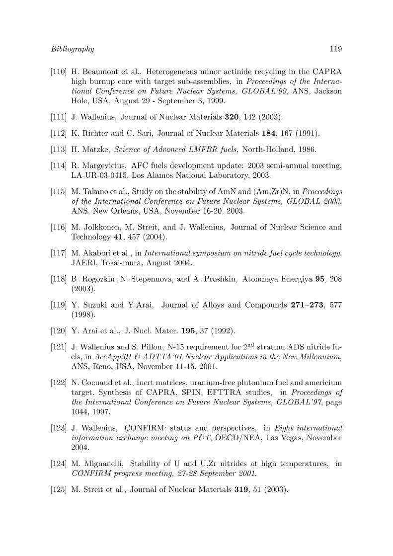
Bibliography 119
[110] H. Beaumont et al., Heterogeneous minor actinide recycling in the CAPRAhigh burnup core with target sub-assemblies, in Proceedings of the Interna-tional Conference on Future Nuclear Systems, GLOBAL’99, ANS, JacksonHole, USA, August 29 - September 3, 1999.
[111] J. Wallenius, Journal of Nuclear Materials 320, 142 (2003).
[112] K. Richter and C. Sari, Journal of Nuclear Materials 184, 167 (1991).
[113] H. Matzke, Science of Advanced LMFBR fuels, North-Holland, 1986.
[114] R. Margevicius, AFC fuels development update: 2003 semi-annual meeting,LA-UR-03-0415, Los Alamos National Laboratory, 2003.
[115] M. Takano et al., Study on the stability of AmN and (Am,Zr)N, in Proceedingsof the International Conference on Future Nuclear Systems, GLOBAL 2003,ANS, New Orleans, USA, November 16-20, 2003.
[116] M. Jolkkonen, M. Streit, and J. Wallenius, Journal of Nuclear Science andTechnology 41, 457 (2004).
[117] M. Akabori et al., in International symposium on nitride fuel cycle technology,JAERI, Tokai-mura, August 2004.
[118] B. Rogozkin, N. Stepennova, and A. Proshkin, Atomnaya Energiya 95, 208(2003).
[119] Y. Suzuki and Y.Arai, Journal of Alloys and Compounds 271–273, 577(1998).
[120] Y. Arai et al., J. Nucl. Mater. 195, 37 (1992).
[121] J. Wallenius and S. Pillon, N-15 requirement for 2nd stratum ADS nitride fu-els, in AccApp’01 & ADTTA’01 Nuclear Applications in the New Millennium,ANS, Reno, USA, November 11-15, 2001.
[122] N. Cocuaud et al., Inert matrices, uranium-free plutonium fuel and americiumtarget. Synthesis of CAPRA, SPIN, EFTTRA studies, in Proceedings ofthe International Conference on Future Nuclear Systems, GLOBAL’97, page1044, 1997.
[123] J. Wallenius, CONFIRM: status and perspectives, in Eight internationalinformation exchange meeting on P&T, OECD/NEA, Las Vegas, November2004.
[124] M. Mignanelli, Stability of U and U,Zr nitrides at high temperatures, inCONFIRM progress meeting, 27-28 September 2001.
[125] M. Streit et al., Journal of Nuclear Materials 319, 51 (2003).
120 Bibliography
[126] M. Streit, Personal communication, 2004.
[127] G. Hofman et al., Progress in Nuclear Energy 31, 83 (1997).
[128] C. Degueldre and J. Paratte, Journal of Nuclear Materials 274, 1 (1999).
[129] N. Chauvin et al., Optimisation of minor actinide fuels for transmutationin conventional reactors (PWR, FR), in Proceedings of the InternationalConference on Future Nuclear Systems, GLOBAL’99, ANS, Jackson Hole,USA, August 29 - September 3, 1999.
[130] H. Matzke et al., Journal of Nuclear Materials 274, 47 (1999).
[131] R. Konings et al., Journal of Nuclear Materials 274, 84 (1999).
[132] A. Languille et al., Journal of Alloys and Compounds 271–273, 517 (1998).
[133] J. Kloosterman and P. Damen, Journal of Nuclear Materials 274, 112 (1999).
[134] J. Wallenius and M. Eriksson, Neutronic design of sub-critical minor actinideburners, submitted to Nuclear Technology, 2004.
[135] N. Novikova, Y. Pashkin, and V. Chekunov, Some features of sub-criticalblankets cooled with lead-bismuth, in Proceedings of the Third InternationalConference on Accelerator-Driven Transmutation Technologies and Applica-tions, ADTTA’99, Praha, Czech Republic, June 7-11, 1999.
[136] A. Rousanov et al., Developing and studying the cladding steels for thefuel elements of the NPIs with heavy coolant, in Proceedings of the Confer-ence Heavy liquid metal coolants in nuclear technology, HLCM’98, Instituteof Physics and Power Engineering, Obninsk, Russia, October 5-9, 1998.
[137] F. Barbier and A. Rusanov, Journal of Nuclear Materials 296, 231 (2001).
[138] D. Pankratov et al., Polonium problem in nuclear power plants with lead-bismuth as a coolant, in Proceedings of the Conference Heavy liquid metalcoolants in nuclear technology, HLCM’98, Institute of Physics and PowerEngineering, Obninsk, Russia, October 5-9, 1998.
[139] T. Mihara, Y. Tanaka, and Y. Enuma, Conceptual design studies on vari-ous types of HLMC fast reactor plants, in Power reactors and sub-criticalblanket systems with lead and lead-bismuth as coolant and/or target mater-ial. Utilization and transmutation of actinides and long lived fission products,IAEA-TECDOC-1348, 2003.
[140] N. Cannon et al., Transient and static mechanical properties of D9 fuel pincladding and duct material irradiated to high fluence, in Effects of Radia-tion on Materials: 15th International Symposium, ASTM STP 1125, editedby R. Stoller, A. Kumar, and D. Gelles, American Society for Testing andMaterials, Philadelphia, USA, 1992.

Bibliography 121
[141] J. Seran et al., Behaviour under neutron irradiation of the 15-15Ti and EM10steels used as standard materials of the penix fuel subassembly, in Effects ofRadiation on Materials: 15th International Symposium, ASTM STP 1125,edited by R. Stoller, A. Kumar, and D. Gelles, American Society for Testingand Materials, Philadelphia, USA, 1992.
[142] S. Porollo et al., Journal of Nuclear Materials 329-333, 314 (2004).
[143] B. Gromov et al., The analysis of operating experience of reactor installa-tions using lead-bismuth coolant and accidents happened, in Proceedings ofthe Conference Heavy liquid metal coolants in nuclear technology, HLMC’98,Institute of Physics and Power Engineering, Obninsk, Russia, October 5-9,1998.
[144] H. Khalil and R. Hill, Nuclear Science and Engineering 109, 221 (1991).
[145] T. Hamid and K. Ott, Nuclear Science and Engineering 113, 109 (1993).
[146] H. Choi and T. Downar, Nuclear Science and Engineering 133, 1 (1999).
[147] P. Hejzlar, M. Driscoll, and M. Kazimi, Nuclear Science and Engineering139, 138 (2001).
[148] T. Takizuka et al., Studies on accelerator driven transmutation systems, inProceedings of the Fifth international information exchange meeting, page383, OECD/NEA, Mol, Belgium, November 25-27, 1998.
[149] W. Maschek et al., Safety analyses for ADS cores with dedicated fuel andproposals for safety improvements, in Proceedings of the IAEA TechnicalCommittee Meeting on Core Physics and Engineering Aspects of EmergingNuclear Energy Systems for Energy Generation and Transmutation, IAEA-TECDOC-1356, Argonne National Laboratory, USA, November 28 - Decem-ber 1, 2000.
[150] M. Eriksson et al., Safety analysis of Na and Pb-Bi coolants in responseto beam instabilities, in Proceedings of the Third International Workshopon Utilisation and Reliability of High Power Proton Accelerators, Santa Fe,USA, May 2002.
[151] K. Tucek et al., IAEA accelerator driven system neutronic benchmark, inFeasibility and motivation for hybrid concepts for nuclear energy generationand transmutation, IAEA–TC–903.3, 1998.
[152] M. Chadwick et al., Nuclear Science and Engineering 131, 293 (1999).
[153] Y. Kim, W. S. Park, T. Y. Song, and C. K. Park, Nuclear Science andEngineering 143, 141 (2003).

122 Bibliography
[154] R. MacFarlane and D. Muir, The NJOY nuclear data processing system,version 91, LA-12740-M, Los Alamos National Laboratory, USA, 1994.
[155] S. Kessler, Nuclear Science and Engineering 117, 254 (1994).
[156] J. Cetnar et al., Transmutation calculations with Monte Carlo continuousenergy burnup system MCB, in Proceedings of the Third International Con-ference on Accelerator-Driven Transmutation Technologies and Applications,ADTTA’99, Praha, Czech Republic, June 7-11, 1999.
[157] R. Cahn, P. Haasen, and E. Kramer, Materials Science and Technology: acomprehensive treatment, volume 10A, VCH, 1994.