Neuro-Audio TM 003 final
37
Technical Manual Neuro-Audio Digital neurophysiological system for EP and OAE TM032.01.003.000 (12.07.10)
Transcript of Neuro-Audio TM 003 final

Technical Manual
Neuro-Audio
Digital neurophysiological system for EP and OAE
TM032.01.003.000(12.07.10)

Neurosoft Ltd. © 2010 5, Voronin str., Ivanovo, 153032, Russia P.O. Box 10, Ivanovo, 153000, Russia Phone: +7 (4932) 24-04-34 Fax: +7 (4932) 24-04-35 E-mail: [email protected] Internet: www.neurosoft.ru

3
Contents Introduction................................................................................................................. 4 1. Digital System Description and Operation ....................................................... 5
1.1. Digital System Function.................................................................................. 5 1.2. Main Specification of Digital System .............................................................. 6 1.3. Digital System Delivery Set ............................................................................ 8
2. Digital System Arrangement and Operation................................................... 10 2.1. Function of Connectors and Indicators......................................................... 11
3. Digital System Mounting and Setting.............................................................. 13 3.1. Personnel Requirements Conducting Digital System Mounting and
Setting.......................................................................................................... 13 3.2. Room Selection and Placement ................................................................... 13 3.3. Reducing Electrical Interference .................................................................. 14 3.4. Unpacking and Check of Delivery Set.......................................................... 16 3.5. Digital System Mounting and Connection to Computer................................ 17
4. Digital System Proper Use ............................................................................... 19 4.1. Safety Measures When Using Digital System.............................................. 19 4.2. Digital System Setting-Up Procedures ......................................................... 19
4.2.1. Power Supply Switch on and Digital System Test ............................... 19 4.3. Troubleshooting............................................................................................ 20 4.4. Exams Using Digital System ........................................................................ 22 4.5. Actions in Emergency................................................................................... 22
5. Digital System Servicing .................................................................................. 23 5.1. General Requirements ................................................................................. 23 5.2. Device Functioning Check Using Test Cavity .............................................. 23 5.3. OAE Probe Check ........................................................................................ 25 5.4. OAE Probe Tip Replacement ....................................................................... 28 5.5. OAE Probe Tip Cleaning .............................................................................. 29 5.6. Digital System Conservation ........................................................................ 30
6. Digital System Current Repair ......................................................................... 31 6.1. General Requirements ................................................................................. 31 6.2. Cables, Adapters and Linkers Repair........................................................... 31 6.3. Computer Interface Cable Repair (USB Cable) ........................................... 31 6.4. Auditory Stimulator Repair ........................................................................... 31 6.5. OAE Probe Repair........................................................................................ 32
7. Digital System Packing and Transportation ................................................... 33 8. Digital System Storage Regulations................................................................ 33 9. Utilization ........................................................................................................... 33 Appendix 1. Electromagnetic Emissions and Immunity ....................................... 34

Neuro-Audio (Technical Manual)
4
Introduction This technical manual is the combined document describing operation and servicing of Neuro-Audio digital neurophysiological system for EP and OAE (hereinafter re-ferred to as “digital system”) intended for objective audiometry carrying out by 1-2 channels and otoacoustic emission (OAE) study.
The document certifies technical parameters of the digital system, which are guar-anteed by the manufacturer.
Do not start working with the digital system before you have read this manual!
You can send your responses and recommendations to the following address:
Post Office Box 10, Ivanovo, 153000, Russia
or by e-mail:
You can find additional information on Neurosoft products on our website:
www.neurosoft.ru
or ask questions by phone:
(4932) 24-04-37 (Service Department)
(4932) 24-04-34

Digital System Description and Operation
5
1. Digital System Description and Operation
1.1. Digital System Function Neuro-Audio digital system is intended for study of auditory brain response (ABR), otoacoustic emission (OAE) by biopotentials recording and input to personal computer (PC) by 1-2 channels and measurement, calculation and analysis of its parameters.
Neuro-Audio digital systems can be used in patient care institutions, diagnostics cen-ters, neurosurgical hospitals and experimental laboratories of the research institutions for:
• brain functional state study;
• auditory tract study.
The general properties when carrying out the exams:
• biopotentials aсquisition by 1-2 channels in any unshielded room;
• auditory stimulation acquisition;
• electrocochleography (ECochG) acquisition;
• auditory brainstem response (ABR) acquisition;
• middle- and long-latency auditory evoked potentials (AEP: MLR, LLR) acquisition;
• vestibular evoked myogenic potentials (VEMP) acquisition;
• cognitive evoked potentials (MMN, P300) acquisition;
• auditory steady-state response (ASSR) acquisition;
• otoacoustic emission study using the techniques: transient evoked otoacoustic emission (TEOAE) and distortion product otoacoustic emission (DPOAE);
• spontaneous otoacoustic emission study (SOAE);
• exam report generation;
• review, store and print of the recorded traces, results of their analysis and exam re-ports.

Neuro-Audio (Technical Manual)
6
1.2. Main Specification of Digital System Table 1. Main specifications of Neuro-Audio digital system.
Parameters Values
EP Channels
Number of channels 2
Sampling rate 200 Hz ÷ 80 kHz
A/D converter 16 bits
Input impedance not less than 90 MΩ
Input noise voltage in 200÷10000 Hz range (RMS) not more than 0.5 µV
High pass filter 0.02÷3000 Hz
Low pass filter 10÷10000 Hz
On/off notch filter 50 or 60 Hz (switchable) not less than 25 dB
Common-mode rejection not less than 100 dB
Auditory Stimulator
Stimulation level for ТА-01 − 0÷127 dB for TDH-39 − 0÷131 dB
for ER-5A — 0÷123 dB for ER-3A — 0÷126 dB
Stimulation frequency 0.05÷100 Hz
Tone stimulation: • tone • stimulus duration
100÷8000 Hz 0.125÷30 ms
Click stimulation: • stimulus duration
100÷30000 µs
Left/right/double-sided stimulation yes
OAE Probe
Stimulus intensity 50÷80 dB
Telephone bandpass flatness: • in the band 600÷3500 Hz • in the band 500÷4500 Hz
not more than 10 dB not more than 20 dB
Microphone bandpass flatness in the band 500÷4500 Hz not more than 6 dB
Stimulus 3rd order intermodulation -80 dB
Microphone system noise -10 dB SPL @ 1 kHz (1 Hz BW)
General Parameters and Specifications
Interface USB
Supply voltage: • electronic units • desktop PC-based system • notebook PC-based system
5 V DC
220/230 V AC (50 Hz) 220/230 V AC (50 Hz) / int.
battery

Digital System Description and Operation
7
Continuation of Table 1
Parameters Values
Dimensions: • electronic unit • footswitch
190×140×50 mm 103×273×43 mm
Weight: • electronic unit • footswitch
not more than 1.0 kg not more than 1.0 kg
Safety BF type
Safety and Electromagnetic Compatibility.
Electromagnetic compatibility (EMC) is provided by conformance to IEC 60601-1-2:2007 requirements.
The digital system is intended for operation in electromagnetic environment, which special features are specified in Appendix 1.
As for safety, the digital system satisfies IEC 60601-1:1988 + A1:1991 + A2:1995, IEC 60601-1-1:2000 and IEC 60601-2-40:1998 requirements. The electronic units are supplied by regulated power supply through USB interface, have double isolation and BF type work parts according to IEC 60601-1.
Interpretation of Symbols on Electronic Unit:
− Attention: consult user and technical manuals.
− Work parts of BF type according to IEC 60601-1.
− Mark of conformance to Russian standards requirements GOST R.
− Mark of measuring device conformance to Russian standards requirements.
− Mark of conformance to 93/42/EEC “Concerning Medical Devices” directive.
− Mark of conformance to 2002/96/EC “On waste electrical and electronic equipment (WEEE)” directive.

Neuro-Audio (Technical Manual)
8
1.3. Digital System Delivery Set Neuro-Audio delivery set includes amplifier electronic unit, patient button, footswitch and software which can be can be supplied to the customer both jointly and sepa-rately, and also accessories and bought articles. The delivery set is given in Table 2 and Table 3.
Table 2. Base delivery set of Neuro-Audio digital system.
Name Document code or main specifications
Number for delivery set
variant, pcs.
Electronic unit NSFT 032201.006 1
Assembled holder NSFT 016201.038 (H-1N) NSFT 016201.038-01 (H-1)
1
Neuro-OAE Accessories for OAE Studies:
OAE probe NSFT 006355.002 1
Set of OAE probe tips ER100-RPT 1
Set of ear tips ER34-KIT, ER10D-KIT 1
Test cavity NSFT 006201.008 1
Dental floss Regular Oral-B (pack – 50 pcs) Oral-B, Ireland 1
OAE probe tip extractor NSFT 006206.016 1
Accessories for EP Studies:
Cup EP electrode with cable1) NSFT 990106.027-01.10 NSFT 990106.031-01.10
NSFT 006106.014 (WPEG-1) NSFT 990106.028-01.10
5
Pup-jack linker NSFT 006103.012 NSFT 006103.019
1
Auditory Stimulators and Accessories for them:
Auditory stimulator (headphones)
NSFT 032305.001 (TDH-39) NSFT 015305.001 (ТА-01)
NSFT 032305.001-01 (TDH-39) NSFT 032305.003 (HDA-280)
1
Consumables:
Electrode adhesive paste 1) TC 9398-011-34616468-2002 1
Abrasive paste for skin preparation 1) Every, Italy 1
Software on CD:
Neuro-Audio.NET software not lower than 1.0.36 version 1
Software module for ABR not lower than 1.0.36 version 1
Software module for VEMP not lower than 1.0.36 version 1
Software module for ECochG not lower than 1.0.36 version 1
Software module for OAE not lower than 1.0.36 version 1

Digital System Description and Operation
9
Continuation of Table 2
Name Document code or main specifications
Number for delivery set
variant, pcs.
Operational Documentation:
Registration certificate RC032.01.003.001 1
Technical manual TM032.01.003.000 1
User manual UM032.01.003.000 1
Notes: 1) The accessories and consumables of similar types can be used if their application is permit-ted in the country.
Table 3. Optional equipment, accessories and software.
Name Document code or main specifications
Number for delivery set
variant, pcs.
Bone vibrator B-71 1
Adapter for bone vibrator NSFT 032103.002 1
Equipment and Software for Cognitive EP Study Using P 300 Technique:
Patient button NSFT 028201.005 1
Software module for P 300 not lower than 1.0.36 version 1
Software and Equipment for ECochG Study:
ECochG electrode Tiptrode ER3-26A ER3-26B
10
Cable for ECochG electrode Tiptrode NSFT 032103.005 1
Insert earphone ER-5A-50 Ω ER3А-10 Ω
1
Set of ear tips ER3-14A 1
Adapter for insert earphone NSFT 032103.001 1
Neuro-Audio.NET software not lower than 1.0.36 version 1
Software module for ECochG not lower than 1.0.36 version 1
Accessories for EP Studies:
Adapter for ABR recording NSFT 032103.006 1
Cable for disposable electrode connection: “button” clip – touch-proof (green, red or black)
NSFT 990103.026-02.05 NSFT 990103.026-03.05 NSFT 990103.026-04.05
1 1 2
Cable for disposable electrode connection:Alligator clip – touch-proof (green, red or black)
NSFT 990103.022-02.10 NSFT 990103.022-03.10 NSFT990103.022-04.10
1 1 2
Disposable surface electrode (100 pcs.) F 3081, FIAB (Italy) 1 pack.
Software for ASSR Study:
Neuro-Audio.NET software not lower than 1.0.36 version 1
Software module for ASSR not lower than 1.0.36 version 1

Neuro-Audio (Technical Manual)
10
Continuation of Table 3
Name Document code or main specifications
Number for delivery set
variant, pcs.
Computer and Electronic Equipment:
Desktop or notebook PC 1) Intel Pentium Celeron (1 GHz and higher) processor in
standard delivery set
1
Printer 1) Laser or jet 1
Notes: 1) All the computer equipment must correspond to IEC 60950 and CISPR 22 for B class.
2. Digital System Arrangement and Operation The digital system principle of operation is based on the recording and input of biopo-tentials and other physiological signals to computer with the purpose of its analysis.
The functional scheme of the digital system is represented on Fig. 1.
Fig. 1. The functional scheme of digital system.
The biopotentials from the electrodes are transferred to the amplifiers, where they are amplified, after that quantized with the use of the analog-digital converter (ADC) and delivered to digital signal processor (DSP) via the 4000 V galvanic isolation. Besides, DSP controls the operation of the amplifiers and ADC via 4000 V galvanic isolation.
The unit microcontroller (MC) provides the connection between DSP of the module and the computer via USB. DSP generates the audio stimulator signal in a digital form which is converted to the analogous form by the digital-analogue converter (DAC), is amplified by audio amplifier and delivered to auditory stimulator.

Digital System Arrangement and Operation
11
The power supply of the galvanically isolated part of amplifier unit, the amplifier mod-ule, is done via galvanically isolated transformer of direct current of patient unit (PU).
The digital system operates under control of PC (IBM PC type) with the mouse, key-board, laser or jet printer and installed licensed Windows operational system. Signal processing, displaying and presentation in different modes after mathematical analy-sis, then storing of the initial data on the hard disk, exam report generation and print-ing is done using PC.
2.1. Function of Connectors and Indicators The external views of the front and side panels of the amplifier unit are represented on Fig. 2 and Fig. 3.
The front panel of the amplifier unit contains touchproof and DIN connectors to attach the electrodes and LED operation indicator (Fig. 2). The channel numbers are marked with Arabic figures “1” and “2”. The operation indicator glows yellow if the unit is con-nected to the computer and glows green at the signal acquisition during the program operation.
Fig. 2. The external view of the front panel.
Operation indicator
Touch-proof connectors
DIN connectors

Neuro-Audio (Technical Manual)
12
The bottom side panel of the amplifier unit contains connectors to attach the auditory stimulator and OAE probe for OAE acquisition (Fig. 3).
Fig. 3. The external view of the side panel.
Connector for OAE probe attachment
Connector for auditory stimulator attachment

Digital System Mounting and Setting
13
3. Digital System Mounting and Setting
3.1. Personnel Requirements Conducting Digital System Mounting and Setting The digital system mounting and setting should be carried out by the person who is empowered by the manufacturer or the technical personnel of the medical institution which is going to use it. It is necessary to remember that digital system mounting ac-curacy defines safety and quality of operation. Further mounting and setting require-ments which define the product safety will be marked by bold and italic fonts in the text.
3.2. Room Selection and Placement Before mounting and setting of digital system, it is necessary to select a place for it, taking into consideration power wiring and protective ground in the room, and also to read the following requirements and recommendations:
Requirements concerning the room selection and the equipment placement:
• At least three tripolar sockets should be provided in the room intended for the equipment use in case you use the system together with the desktop PC and two tripolar sockets if you use the system together with the notebook PC.
• The recommended distance from the electronic unit to the short-wave or microwave therapeutic equipment is not less than 5 meters.
• The patient environment (within 1.5 meters) should contain only the elec-tronic unit being the medical device with the required safety level. The fact is that the safety level of the computer equipment is insufficient for the use in the patient environment. Hence, a patient must not contact with the metal parts of computer equipment cases and the personnel must not touch simul-taneously these parts and patient body. If the computer equipment used in the system corresponds to IEC 50267.0 or is connected via the isolation transformer corresponding to IEC 50267.0, and the isolation from the com-puter network is provided via the special isolation device corresponding to IEC 50267.0, then it is not obligatory to fulfill the given requirement.
• It is recommended to place the electronic unit on the maximum possible distance from power cables, switchboards, and different powerful electrical devices which can emit electromagnetic fields of mains frequency.
Requirements to mains:
• The use of electric mains in which the neutral conductor and protective ground are combined is strongly prohibited.

Neuro-Audio (Technical Manual)
14
• The device should be supplied from 230 V mains equipped with TN-S or TN-C-S ground system (according to IEC 60364-1).
• Before the digital system setting, the electrician must check the quality of standard tripolar sockets and the integrity of the protective ground circuit. See the detailed information concerning the necessity to ground in chapter 3.3 “Reducing Electrical Noise” of this manual.
• In case the system components are connected to several tripolar sockets, make sure they are grounded to one and the same protective ground circuit. Otherwise, there is a danger of several tens of amperes of compensating cur-rent leakage through the system connecting cables that leads to the equip-ment break-down.
3.3. Reducing Electrical Noise There are some factors that may impact the ABR test results, they are the electrodes placement and its impedance, patient’s condition, ambient noise, however, the most important one is the electrical interference that can worsen the result greatly. The in-formation concerning the electrical interference reduction is given in this chapter.
Grounding is crucial for good ABR waves acquisition and safe operation.
The device power cord contains a ground lead (typically indicated by yellow and green colors), but often the ground at the test site may not be sufficient.
Try to ground the patient bed if it is made of metal. Remember to turn off all other electrical equipment not used in the room, especially sources with neon lights.
In some cases, it may be necessary to find another test location if there is too much ambient or electrical noise.
Try also to move the test site within the room; patient might be close to a power cord etc. perhaps hidden in the wall close to patient and electrodes.
Electrical interference may also appear through the ground lead if this is intercon-nected to many computers, autoclaves, instruments using high power etc. In this case a dedicated ground for the ABR recording site should be established.
Avoid any mixing of cables ex. USB cables/power cord etc. mixed up with the electrodes cable used for the EP system.
Some times the ground lead is found inside the wall outlet, but is not connected to ground.
In these cases where the ground is not connected or even missing, the ABR re-cordings will be distorted greatly.

Digital System Mounting and Setting
15
Neuro-Audio digital system is connected to the ground lead via a ground contact of tripolar outlet. If the ground lead is not connected, the digital system will pick up elec-trical noise/interference.
This will be seen on the screen as very large harmonic distortion traces completely overlaying/destroying the ABR traces.
Some notebooks do not provide the notebook ground connection to the outlet ground. If you use such notebook as a part of the digital system, it is required to take the spe-cial measures to ensure the notebook ground contact to the outlet ground. To do this, use the power supply units with the required contact. You can identify visually such power supply unit by the tripolar connector for mains lead attachment. To make sure that there is a connection between notebook ground and outlet ground, measure the impedance between protective ground pin of power supply unit outlet and ground con-nector pin attached to notebook. The impedance should not exceed 0.1 Ω.
Check the ground for proper and correct function of the digital system.
Due to high voltage, only experienced technicians or properly trained staff must change and check the ground.
To check and verify the ground, you can apply various methods:
1. Use a dedicated ground tester.
2. Voltage/impedance comparison from the wall outlet ground lead to a triangle of earth rods. Ground should have max 8 Ω, and 0.5 V deviation compared to true ground.
3. More simple check is to use a voltage meter and measure directly in the wall out-let. Please verify these specifications:
• the voltage between phase (hot) socket and zero (neutral) socket must be a stabile 230 V for Europe /110 V for US (country specific);
• the voltage between phase (hot) socket and ground socket, 230 V for Europe /110 V for US (country specific). The voltage as in p. 3.1 (see above) should be the same as with a deviation of max 5 V.
If the recorded voltage is much less than 230 V Europe / 110 V US, the ground is not connected to true ground. Even though you can see the lead inside the wall outlet this lead is not connected to true ground.
• the voltage between zero (neutral) and ground, it must be 0 V.
Neuro-Audio (Technical Manual)
16
If the recorded voltage differs much from 0 V, such as 110 (50 US) volt ground is not connected to true ground. Even though you can see the lead inside the wall outlet this lead is not connected to true ground.
The ABR equipment must be connected to a proper true ground for safe operations and in order to get good ABR recordings.
To obtain the best ground, a separate ground dedicated to the ABR recording site should be wired and connected directly to true ground using at least three earth rods.
The best test site for ABR recordings is:
• an electric magnetic shielded room – is also often soundproof;
• dedicated separate ground for the ABR recording site only.
Besides, it is recommended to observe the following:
• light and other electrical equipment not being used are turned off – as the patient will work as an antenna and pick up electrical interferences;
• a soundproof room;
• no patients / visitors etc. to disturb the patient trying to relax.
3.4. Unpacking and Check of Delivery Set In case the box with the digital system was under conditions of the excessive moisture or low temperature which differs vastly from the working conditions, it is necessary to place it in the room and leave for 24 hours in normal conditions.
Unpack the box and take out the digital system components. The delivery set should correspond to the packing report.
The computer equipment packed in the separate boxes should be opened according to user and technical manuals for these products.
Check the digital system components to make sure that there is no external damage.

Digital System Mounting and Setting
17
3.5. Digital System Mounting and Connection to Computer If you purchase the digital system together with the computer, the equipment is deliv-ered with installed and configured software. If you purchase the digital system sepa-rately, please install the software from the compact disk (included in the delivery set) to computer. The software must be installed before the first connection of digital sys-tem to the computer. Study carefully the corresponding paragraph of the user manual before starting to work.
In case the installation disk is missing, you can always download all the necessary components and last version of the program distributive from our site: http://www.neurosoft.eng/eng/soft/. To get an access to the files, enter the name and the password which you can obtain in the commercial department of Neurosoft Ltd.
The digital system consists of one electronic unit and can be supplied with patient but-ton depending on the delivery set variant (Fig. 4). The electronic unit and the patient button can be connected to the computer either directly or using USB hub (it is not shown in the Fig. 4). Remember, that electronic unit and patient button must be at-tached to:
• the same USB controller, that is to the same USB-hub;
• to the alongside USB connectors;
• to different USB hubs attached to the same USB controller.
Do not use passive USB hubs that are not connected to the mains. The connection to USB connectors on PC monitor and computer keyboard does not ensure the correct device operation.

Neuro-Audio (Technical Manual)
18
ear
Fig. 4. Neuro-Audio digital system connection to computer.
Place the holder as near as possible to the place of exam carrying out and fix the Neuro-Audio electronic unit on it. Connect all the necessary equipment. The electri-cal units can be connected to PC when the power supply is on or off. If the window
shown on the Fig. 5 appears after the digital system connection, press but-ton, without inserting the installation disk.
Fig. 5. The window of new equipment wizard.
If “Neurosoft software has not been tested on the Windows XP compatibility” message appears on the screen, press the button “Continue”.

Digital System Proper Use
19
4. Digital System Proper Use
4.1. Safety Measures When Using Digital System To provide safety measures and exclude the possibility of medical staff’ or pa-tient’ electric trauma, the medical staff is PROHIBITED:
• To use digital system, mounting and setting of which was done incorrectly, without following this manual instructions.
• To connect digital system and surgical HF equipment to the patient (it can cause patient’s flash-burn in the places of electrode placement and digital system dam-age).
• To connect any products, which are not included in digital system delivery set, to the electrode jacks.
• To eliminate faults by opening of the components included in the delivery set.
• To provide exams when the electronic unit box, computer or other devices compris-ing digital system are opened.
• To connect patient electrodes to protective ground or other conducting surfaces.
4.2. Digital System Setting-Up Procedures Operating Limitations:
• Ambient temperature is from +10 to +35°С.
• Relative humidity is to 80% at +25°С temperature.
• Atmospheric pressure is (760±30) mm merc. col.
Before power supply switching make sure that digital electronic unit and computer equipment cases have no apparent mechanical failures which can represent a dan-ger.
4.2.1. Power Supply Switch on and Digital System Test Digital system power supply switch on is done by pressing the “Power” key of your PC. The electronic unit has no power supply switch and is constantly connected to PC. Power supply switch on occurs after PC operational system loading and Neuro-Audio.NET program start.
Neuro-Audio (Technical Manual)
20
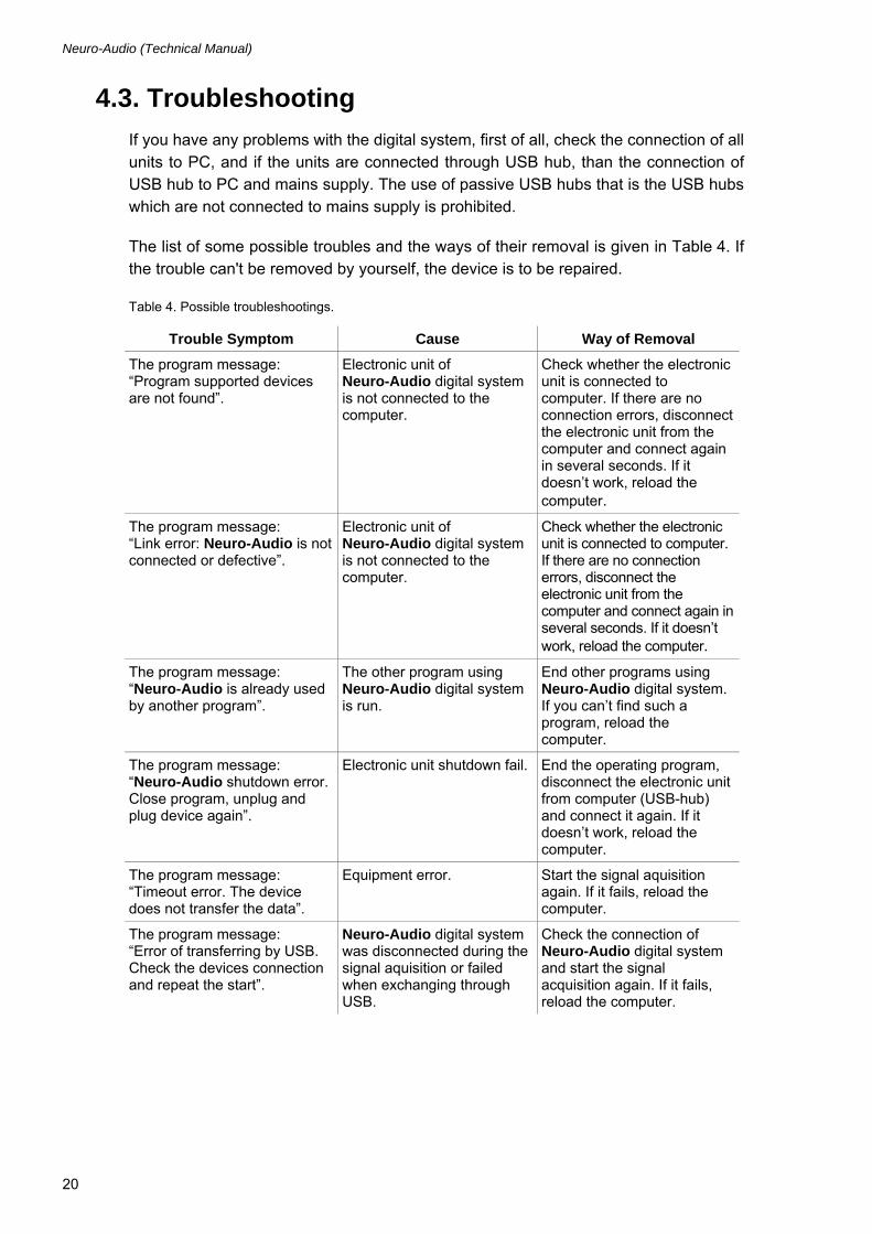
4.3. Troubleshooting If you have any problems with the digital system, first of all, check the connection of all units to PC, and if the units are connected through USB hub, than the connection of USB hub to PC and mains supply. The use of passive USB hubs that is the USB hubs which are not connected to mains supply is prohibited.
The list of some possible troubles and the ways of their removal is given in Table 4. If the trouble can't be removed by yourself, the device is to be repaired.
Table 4. Possible troubleshootings.
Trouble Symptom Cause Way of Removal The program message: “Program supported devices are not found”.
Electronic unit of Neuro-Audio digital system is not connected to the computer.
Check whether the electronic unit is connected to computer. If there are no connection errors, disconnect the electronic unit from the computer and connect again in several seconds. If it doesn’t work, reload the computer.
The program message: “Link error: Neuro-Audio is not connected or defective”.
Electronic unit of Neuro-Audio digital system is not connected to the computer.
Check whether the electronic unit is connected to computer. If there are no connection errors, disconnect the electronic unit from the computer and connect again in several seconds. If it doesn’t work, reload the computer.
The program message: “Neuro-Audio is already used by another program”.
The other program using Neuro-Audio digital system is run.
End other programs using Neuro-Audio digital system. If you can’t find such a program, reload the computer.
The program message: “Neuro-Audio shutdown error. Close program, unplug and plug device again”.
Electronic unit shutdown fail. End the operating program, disconnect the electronic unit from computer (USB-hub) and connect it again. If it doesn’t work, reload the computer.
The program message: “Timeout error. The device does not transfer the data”.
Equipment error. Start the signal aquisition again. If it fails, reload the computer.
The program message: “Error of transferring by USB. Check the devices connection and repeat the start”.
Neuro-Audio digital system was disconnected during the signal aquisition or failed when exchanging through USB.
Check the connection of Neuro-Audio digital system and start the signal acquisition again. If it fails, reload the computer.

Digital System Proper Use
21
Continuation of Table 4.
Trouble Symptom Cause Way of Removal
The program message: “Service Pack 1 should be installed for operation of the equipment with Windows XP”.
The first version of Windows XP installed in your computer contains the errors resulting in the improper operation of USB devices.
Install Windows XP Service Pack 1, or the more late version of Windows (preferable).
Unused at the moment electrodes are connected to the amplifier, these are electrodes which are not set on a patient and can cause the noise.
Disconnect the unused at the moment electrodes from the amplifier.
Patient's electrodes are set bad.
Start the impedance measurement and obtain the accepted values. In case of electrodes fault (for example, break), replace them.
Bad grounding of Neuro-Audio digital system.
Ground the computer safely. Send for electrician to check the quality of tripolar sockets and the integrity of the protective ground circuit.
High supply-line noise is in recorded signal (frequency – 50 (60) Hz or divisible to it – 100 (120) Hz, 150 (180) Hz, etc.).
The presence of powerful noise sources (X-ray equipment, physiotherapeu-tic room, powerful refrigerating systems, electric motors, electric welding, etc.).
Try to switch off or move off these powerful devices on the bigger distance. If it is impossible, try to obtain better parameters of the Neuro-Audio digital system grounding.
The program message: “Processing error. The system is overloaded. Repeat starting”.
The computer processor was overloaded and could not receive the next data block from Neuro-Audio digital system. If this message appears rarely (not more 1-2 times per day), it is not considered as trouble.
End all applications except Neuro-Audio.NET program (if they are started) and restart signal aquisition. If it doesn't work, reload the computer. If the trouble does not disappear, then probably, your computer processing speed is not enough. Minimal computer requirements are given in the user manual.
The stimulation device (OAE probe, headphones, etc.) is not connected (or connected unreliably) to the stimulator unit.
Make sure that the stimulation device is connected to the stimulator unit reliably.
When starting the signal acquisition, the stimulus is absent.
The connection between stimulator and computer is broken.
Execute Setup|Hardware reset menu command and restart. If it fails, reload the computer.
Neuro-Audio (Technical Manual)
22
4.4. Exams Using Digital System Before carrying out exams, it is necessary to set up the digital system and other equipment taking into consideration the recommendations given in the user manual.
Exam performing includes the following stages:
• preparation to acquisition (electrodes, stimulators set up);
• signal recording;
• analysis and printing of the results.
Before electrodes placement, it is necessary to degrease the skin by alcohol where the electrodes are set. The use of electrode abrasive paste for EP electrodes is pref-erable. Electrodes connection and placement can be conducted when the digital sys-tem is switched on. The more detailed information concerning the operation with elec-trodes is described in the user manual.
After placement of surface electrodes it is necessary to control the electrode setting quality using the impedance measurement. First of all, the impedance measurement mode should be switched on (see the “User Manual”).
The order of signal recording and records analysis is given in details in the user man-ual.
After finishing of the recording, the electrodes and sensors should be taken off the pa-tient and disinfected (see the “User Manual”).
If the next patient is not planned till the end of the working day, the digital system should be switched off. To do it, exit the digital system software and then switch off the computer and the printer.
4.5. Actions in Emergency In the cases of electrical insulation disturbance of any digital system component which causes the emergency (fire, mechanical failure, flood, medical staff evacuation) and threat of patient or staff electrical shock, it is necessary to de-energize the digital sys-tem completely.

Digital System Servicing
23
5. Digital System Servicing
5.1. General Requirements Safety measures when servicing conforms to the ones described in the chapter 4 Digital System Proper Use”.
Qualification requirements to the medical staff are listed in chapter 3.1 “Personnel Requirements Conducting Digital System Mounting and Setting”.
Digital system servicing in the process of operation includes the external examination, check of connectors and cables, removal of contaminations from the units’ surface us-ing wet fabric.
Servicing of the bought articles included in the digital system is conducted according to user and technical manuals or typical rules.
When detecting the troubles it is recommended to use the information given in 4.3 “Troubleshooting” chapter. If the troubles can’t be eliminated using EEG system con-trol units or by restart, it should be switched off and checked by the specialist.
Type, volume and periodicity of the servicing except specified in this chapter, are not determined.
The delivery set check is done by conformity to the device packing report.
5.2. Device Functioning Check Using Test Cavity The check of OAE acquisition channel functioning should be performed in a quiet room.
To check the functioning in TEOAE mode, connect the OAE probe to the device, re-move the ear tip and insert OAE probe to the test cavity firmly. Start TEOAE acquisi-tion (see the description in corresponding chapter of user manual).

Neuro-Audio (Technical Manual)
24
As far as the test cavity does not provide the normal functioning cochlea hair cells, the test result should be “REFER”. The value of sum and difference of A&B and A-B traces should be lesser than 0 (at 1000 averagings) (Fig. 6).
Fig. 6. The result of TEAOE check in test cavity.
If it is not so, make sure it is quiet in the room, the OAE probe sensitivity is specified correctly.
The functioning in DPOAE mode is checked with the connected OAE probe inserted to the test cavity. Start DPOAE test. During the frequency response calibration (“Seal control” mode) make sure that two similar traces of stimulus spectrum from first and second telephones appear on the screen (Fig. 7).
Fig. 7. The frequency response calibration.

Digital System Servicing
25
After the test finishing, the test result should be “REFER”. The emission should lack for all frequencies (Fig. 8).
Fig. 8. The result of DPAOE check in test cavity.
After the test finishing, close the test (Exam|Close menu command). When “Save changes?” message box appears on the screen, press “No” button.
5.3. OAE Probe Check During the operation with the device, probably you will need to check the OAE probe running order. The check should be done if you doubt about the probe operability.
To check the OAE probe, apply the test cavity supplied with the device. The run of the check while the probe is out of the test cavity will cause the wrong results!
The check is performed in special “OAE probe check” mode. In this mode the com-parison of OAE probe responses with already set responses is carried out.

Neuro-Audio (Technical Manual)
26
Start Neuro-Audio.NET program, execute Setup|Change menu command. Select “Hardware” page and press “OAE Probe Check” button (Fig. 9).
Fig. 9. Device settings.
“OAE Probe Check” window will appear on the screen (Fig. 10).
Fig. 10. “OAE Probe Check” window.
Connect OAE probe to the device, replace the OAE probe tip and insert the OAE probe to the test cavity firmly.
To run the check, press “Check” button.

Digital System Servicing
27
It is prohibited to press “New” button as it can lead to loss of data concern-ing OAE probe responses and the check of this probe will become impos-sible. The given button is used only for the recording of specifications of new probe at the replacement as described below.
The check results are displayed on the screen as several bars directed up and down. The OAE probe check is performed on several frequencies, each bar (for each probe loudspeaker) corresponds to one frequency. If the bar color is green, the OAE probe is operable, in case the bar is red, the probe is faulty (Fig. 11).
Fig. 11. The results of OAE probe check.
If the OAE probe did not pass the check even on one of the frequencies and the mes-sage concerning the necessity to replace the probe appears on the screen, carry out the following operations:
• Try to extract the probe from the test cavity and insert it again. After that run the check once again. If the probe passed the check, it means, it was inserted incor-rectly.
• Try to clean the probe tip (see chapter 5.5 “OAE Probe Tip Cleaning”). If the OAE probe passes the repeated check, it means, the OAE probe tip was clogged.
• In case two first operations did not work, try to replace the OAE probe tip (see chapter 5.4 “OAE Probe Tip Replacement”).
• If the OAE probe tip replacement did not work, replace OAE probe.

Neuro-Audio (Technical Manual)
28
After OAE probe replacement, it is required to memorize its responses us-ing “OAE Probe Check” window (Fig. 10). To do this, press “New” button and wait for the progress bar finishing and “Done” message will appear on the screen (Fig. 12).
Fig. 12. Saving of new OAE probe specifications.
After that, you can press “Close” button. The message with “Remember this probe as a new one?” question will appear on the screen (Fig. 13).
Fig. 13. Confirmation to save new OAE probe specifications.
If you pressed by chance “New” button in “OAE Probe Check” window (Fig. 10) or are not sure in your actions, press “No” button. To memorize the data of your new probe for its future check, press “Yes” button.
5.4. OAE Probe Tip Replacement If the OAE probe tip is clogged, it should be replaced. The OAE probe tip should be taken off in the following order.
To remove the OAE probe tip, use the special OAE probe tip extractor (Fig. 14 (a)). To do this, insert the extractor under the latches firmly (Fig. 14 (b)) and slide the probe tip off and discard.
Align a replacement tip with the front of the probe (Fig. 14 (c)). The tip will only fit in one direction. If the tip does not fit securely on the probe, remove the probe tip and

Digital System Servicing
29
reorient it. Press lightly on the tabs to snap them into place. The tabs should be flush with the outside of the probe (Fig. 14 (d)).
If the probe tip is not inserted completely, the digital system will not perform a test.
(a) (b) (c) (d)
Fig. 14. The replacement of OAE probe tip.
5.5. OAE Probe Tip Cleaning In case of the front tubes clogging (Fig. 15), they should be cleaned.
Fig. 15. OAE probe tip.
To clean the tip, use Dental floss “Superfloss Regular Oral-B” (Fig. 16) included in the delivery set.
Fig. 16. Dental floss “Superfloss Regular Oral-B”.

Neuro-Audio (Technical Manual)
30
Each dental floss is used only once for the cleaning of one front tube. To do this, pass the thin floss end through the front tube from the tip inner side and run it through whole front tube (Fig. 17, Fig. 18).
Pass the floss through the front tube only once! To clean other front tube, use the new floss.
Fig. 17. Cleaning of OAE probe tip (1).
Fig. 18. Cleaning of OAE probe tip (2).
5.6. Digital System Conservation The digital system components including accessories and operational documentation should be packed in separate plastic sachets and then placed in a manufacturer package.

Digital System Current Repair
31
6. Digital System Current Repair
6.1. General Requirements Digital system repair requires special training of the technical staff and special equip-ment and service software which you can receive from the manufacturer or the repre-sentative of the firm. The repair connected with the electronic unit opening is prohib-ited. The repair of computer equipment can be conducted by dedicated establish-ments for computer equipment service.
The digital system current repair includes the component parts and cables repair. The component parts repair when connecting to digital system is prohibited.
When conducting current repair, all the units must be switched off.
6.2. Cables, Adapters and Linkers Repair Cables are examined externally, and the circuits are checked for short circuit or break. In case of cable break, it is necessary to replace or cut it if the cable length is suffi-cient.
6.3. Computer Interface Cable Repair (USB Cable) Computer interface cable (Fig. 19) is examined externally, and the circuit is checked for short circuit or break. In case of cable failure, it should be replaced or repaired by shortening the length. When replacing it is necessary to pay attention to cable mark-ing. The marking of wire size on cable should be either 28AWG/2C+24AWG/2C, or 28AWG/2C+22AWG/2C, or 28AWG/2C+20AWG/2C.
Fig. 19. The computer interface cable electrical schematic.
6.4. Auditory Stimulator Repair Auditory stimulator (Fig. 20) is examined externally, and circuit resistance of dynamic head and cable are measured. The measured value should be within the range from 90 up to 110 Ω. When detecting the break or short circuit it is necessary to open cable jack unit and check it. If the failure is not discovered, open the auditory stimulator unit and measure each cable and coil of dynamic head. If the cable break is detected, see

Neuro-Audio (Technical Manual)
32
the instruction on the USB cable repair. If the dynamic head failure is detected, ad-dress to manufacturer for the further repair.
Fig. 20. The auditory stimulator electrical schematic.
6.5. OAE Probe Repair OAE probe is examined externally for cable failure. Control of telephone circuits from connector side is done according to schematic given on Fig. 21. Telephone resistance should be 395 Ω ± 10%. If the break or short circuit is discovered, disassemble the cable connector case and examine it. If the cable break is detected, see the instruc-tions on USB cable repair. If the failure is not detected, address to manufacturer for the further repair.
Fig. 21. The OAE probe electrical schematic.

Digital System Packing and Transportation
33
7. Digital System Packing and Transportation The package should conform to the one accepted when manufacturing and delivering. In case the factory package is damaged, but the long-term system storage and trans-portation is expected, follow the given recommendations:
• The digital system with operational documentation should be packed in plastic sa-chets and cardboard boxes.
• The cardboard boxes should be covered by the paper tape or pressure sensitive adhesive.
The digital systems can be transported by all kinds of covered carries (except non-heated airplane pods) according to rules of goods transportation for each mode of transport at temperature varying from -50 up to +50 C.
8. Digital System Storage Regulations The digital system should be stored in the manufacturer package in an enclosed space at +5 up to +40°С and 80% maximal relative humidity (measured at 25°С tem-perature). The room air should be free from any dust, acid vapors, alkali vapors, cor-rosive gases and other injurous admixtures which can cause the corrosion.
The digital systems should be put on the shelves not more than in four rows.
9. Utilization The device utilization is performed according to the current country legislation where the equipment is used.

Neuro-Audio (Technical Manual)
34
Appendix 1. Electromagnetic Emissions and Immunity
Guidance and manufacturer’s declaration – electromagnetic emissions
The digital system is intended for use in the electromagnetic environment specified below. The customer or the user of the digital system should assure that it is used in such an environment.
Emissions test Compliance Electromagnetic environment — guidance
RF emissions CISPR 11
Group 1 The digital system uses RF energy only for its internal function. Therefore, its RF emissions are very low and not likely to cause any interference in nearby electronic equipment.
RF emissions CI5PR 11
Class A
Harmonic emissions IEC 61000-3-2
Not applicable
Voltage fluctuations' flicker emissions IEC 61000-3-3
Not applicable
The digital system is suitable for use in all establishments, including domestic establishments and those directly connected to the public low-voltage power supply network that supplies buildings used for domestic purposes.

Appendix 1. Electromagnetic Emissions and Immunity
35
Guidance and manufacturer’s declaration – electromagnetic immunity
The digital system is intended for use in the electromagnetic environment specified below. The customer or the user of the digital system should assure that it is used in such an environment.
Immunity test IEC 60601 test level Compliance level Electromagnetic environment -guidance
±6 kV − contact
±6 kV
Electrostatic discharge (ESD) IEC 61000-4-2
±8 kV − air
±8 kV
Floors should be wood, concrete or ceramic tile. If floors are covered with synthetic material, the relative humidity should be at least 30%.
±2 kV − for power
supply lines
Electrical fast transient/burst IEC 61000-4-4
±1 kV − for input/output lines
Not applicable Not applicable
±1 kV differential
mode
Surge IEC 61000-4-5
±2 kV common mode
Not applicable Not applicable
<5% UT
(>95% dip in UT) for 0,5 and 1 cycle
20 ms
40% UT (60% dip in
UT) for 5 cycles
100 ms
70% UT (30% dip in
UT) for 25 cycles
500 ms
120% UT (20% dip in UT) for 25 cycles
500 ms
Voltage dips, short interruptions and voltage variations on power supply input lines IEC 61000-4-11
<5% UT (>95% dip in UT) for
5 s
5000 ms
Mains power quality should be that of a typical commercial or hospital environment. If the user of the digital system requires continued operation during power mains interruptions, it is recommended that the digital system be powered from an uninterruptible power supply or a battery.
Power frequency magnetic field IEC 61000-4-8
3 A/m
3 A/m
Power frequency magnetic fields should be that of a typical commercial or hospital environment.
Note: UT – is the a.c. mains voltage prior to application of the test level.

Neuro-Audio (Technical Manual)
36
Guidance and manufacturer’s declaration – electromagnetic immunity
The digital system is intended for use in the electromagnetic environment specified below. The customer or the user of the digital system should assure that it is used in such an environment.
Immunity test IEC 60601 test level
Compliance level Electromagnetic environment -guidance
Conducted RF IEC 61000-4-6 Radiated RF IEC 61000-4-3
3 Vrms 150 kHz to 80 MHz outside ISM bands 1)
3 V/m 80 MHz to 2.5 GHz
3 Vrms
3 V/m
Portable and mobile RF communications equipment should be used no closer to any part of the digital system, including cables, than the recommended separation distance calculated from the equation applicable to the frequency of the transmitter:
Pd 17.1=
Pd 17.1= (80 MHz to 800 MHz);
Pd 33.2= (800 MHz to 2.5 GHz). Field strengths from fixed RF transmitters, as determined by an electromagnetic site survey1), should be less than the compliance level in each frequency range 2). Interference may occur in the vicinity of equipment marked with the following symbol:
1) Field strengths from fixed transmitters, such as base stations for radio (cellular/cordless) telephones and land mobile radios, amateur radio, AM and FM radio broadcast and TV broadcast cannot be predicted theoretically with accuracy. To assess the electromagnetic environment due to fixed RF transmitters, an electromagnetic site survey should be considered. If the measured field strength in the location in which the digital system is used exceeds the applicable RF compliance level above, the digital system should be observed to verify normal operation. If abnormal performance is observed, additional measures may be necessary, such as re-orienting or relocating the digital system. 2) Over the frequency range 150 kHz to 80 MHz, field strengths should be less than 1 V/m. Notes: 1. At 80 MHz and 800 MHz, the higher frequency range applies. 2. These guidelines may not apply in all situations. Electromagnetic propagation is affected by absorption and reflection from structures, objects and people.

Appendix 1. Electromagnetic Emissions and Immunity
37
Recommended separation distances between portable and mobile RF communications equipment and digital system
The digital system is intended for use in an electromagnetic environment in which radiated RF disturbances are controlled. The customer or the user of the digital system can help prevent electromagnetic interference by maintaining a minimum distance between portable and mobile RF communications equipment (transmitters) and the digital system as recommended below, according to the maximum output power of the communications equipment.
Separation distance according to frequency of transmitter, m Rated maximum outputpower of transmitter, W 150 kHz up to 80 MHz
outside ISM bands
Pd 17.1=
80 MHz to 800 MHz
Pd 17.1=
800 MHz to 2.5 GHz
Pd 23.2= 0.01 0.117 0.117 0.233
0.1 0.369 0.369 0.738
1 1.167 1.167 2.333
10 3.689 3.689 7.379
100 11.667 11.667 23.333
Notes: 1. At 80 MHz and 800 MHz, the separation distance for the higher frequency range applies. 2. These guidelines may not apply in all situations. Electromagnetic propagation is affected by absorption and reflection from structures, objects and people. 3. For transmitters rated at a maximum output power not listed above, the recommended separation
distance d in meters (m) can be determined using the equation applicable to the frequency of the
transmitter, where Р is the maximum output power rating of the transmitter in watts (W) according to the transmitter manufacturer.