
Neuralink's Augmented Brain Project
12
The material in this tutorial is based in part on the work presented in [1] and my own research. For more informaon, please write to: [email protected] © 2020 K. N. Toosi University of Technology Introducon Our brain consists of about 100 billion of cells called neurons. Neurons come in many complicated shapes, but generally they have a dendric arbor, a cell body and an axon. The neurons of your brain connect to form a large network through axon’s dendrite junc- ons called synapses. At these connecon points, neurons communicate with each oth- er using chemical signals called neurotrans- miers. Neurotransmiers are released from the end of an axon in response to an electrical spike called an acon potenal. Everything we hear, see, perceive, feel, think etc. are all ac- on potenals or in another word, neuro- spike impulses. When a cell receives enough of the right kind of neurotransmier input, a chain reacon is triggered that causes an ac- on potenal to fire and the neuron to in- turn relay messages to its own downstream synapses. Acon potenals produce an elec- tric field that spread from a neuron and can be detected by placing an electrodes nearby, allowing recording of the informaon repre- sented by the neuron. Neuron acon potenal or neurospikes are the fundamental elements of communicaon within the brain which is necessary for every brain machine interface (BMI) device and technology to record these signals in real me. BMIs combine methods, approaches, and concepts derived from neurophysiology, computer science and engineering in an effort to establish real-me bidireconal links between living brains and arficial actu- ators. he emerging field of Brain machine interfaces (BMIs) hold promise for rehabilitaon and treatment of peo- ple suffering neurological disorders. Howev- er, since BMIs bandwidth are restricted as a result of modest channels count, their poten- als for medical approaches are limited. Neuralink have built arrays of small and flexi- ble electrode threads, with as many as 3072 electrodes per array distributed across 96 threads. Neuralink’s technology is difficult to implant precisely because it’s so flexible. To combat this problem, the company has de- veloped a neurosurgical robot capable of in- serng six threads (192 electrodes) per mi- nute. The surgical robot being used for im- plantaon and further manipulaon of these threads play an important role in this pro- cess. This surgical robot must be used under the direct supervision of a human neurosur- geon to layout where the threads should be placed. Beside that the use of this robot is inevitable due to many complexies the sur- gery staff may face such as imaging the blood vessels and other ssues and avoiding trau- ma or other injuries to blood vessels or other structures. The electrode array is packaged into a small implantable device that contains custom chips for low-power on-board ampli- ficaon and digizaon: the package for 3,072 channels occupies less than (23 × 18.5 × 2) mm 3 . T Neuralink's Augmented Brain Project Babak Seddighi
Transcript of Neuralink's Augmented Brain Project

The material in this tutorial is based in part on the work presented in [1] and my own research. For more information, please write to: [email protected] © 2020 K. N. Toosi University of Technology
Introduction
Our brain consists of about 100 billion of cells called neurons. Neurons come in many complicated shapes, but generally they have a dendritic arbor, a cell body and an axon. The neurons of your brain connect to form a large network through axon’s dendrite junc-tions called synapses. At these connection points, neurons communicate with each oth-er using chemical signals called neurotrans-mitters. Neurotransmitters are released from the end of an axon in response to an electrical spike called an action potential. Everything we hear, see, perceive, feel, think etc. are all ac-tion potentials or in another word, neuro-spike impulses. When a cell receives enough of the right kind of neurotransmitter input, a chain reaction is triggered that causes an ac-tion potential to fire and the neuron to in-turn relay messages to its own downstream synapses. Action potentials produce an elec-tric field that spread from a neuron and can be detected by placing an electrodes nearby, allowing recording of the information repre-sented by the neuron. Neuron action potential or neurospikes are the fundamental elements of communication within the brain which is necessary for every brain machine interface (BMI) device and technology to record these signals in real time. BMIs combine methods, approaches, and
concepts derived from neurophysiology,
computer science and engineering in an
effort to establish real-time bidirectional
links between living brains and artificial actu-
ators.
he emerging field of Brain machine interfaces (BMIs) hold promise for rehabilitation and treatment of peo-
ple suffering neurological disorders. Howev-er, since BMIs bandwidth are restricted as a result of modest channels count, their poten-tials for medical approaches are limited. Neuralink have built arrays of small and flexi-ble electrode threads, with as many as 3072 electrodes per array distributed across 96 threads. Neuralink’s technology is difficult to implant precisely because it’s so flexible. To combat this problem, the company has de-veloped a neurosurgical robot capable of in-serting six threads (192 electrodes) per mi-nute. The surgical robot being used for im-plantation and further manipulation of these threads play an important role in this pro-cess. This surgical robot must be used under the direct supervision of a human neurosur-geon to layout where the threads should be placed. Beside that the use of this robot is inevitable due to many complexities the sur-gery staff may face such as imaging the blood vessels and other tissues and avoiding trau-ma or other injuries to blood vessels or other structures. The electrode array is packaged into a small implantable device that contains custom chips for low-power on-board ampli-fication and digitization: the package for 3,072 channels occupies less than (23 × 18.5 × 2) mm3 .
T
Neuralink's Augmented Brain Project Babak Seddighi
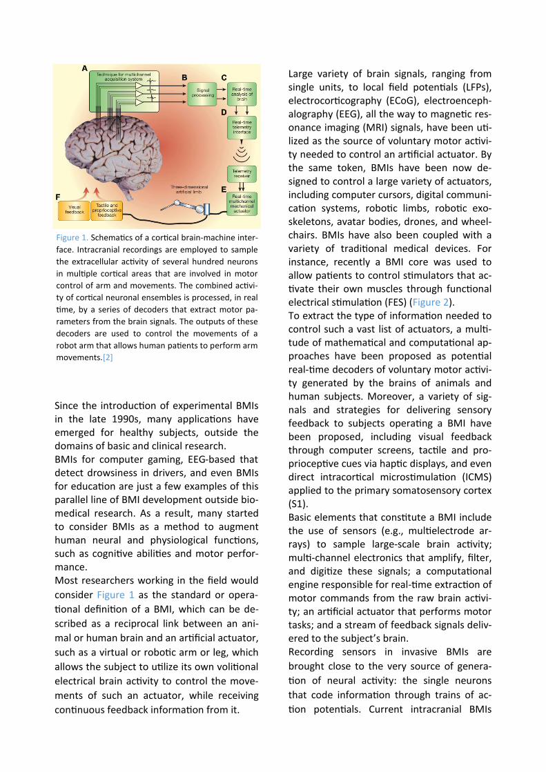
Large variety of brain signals, ranging from single units, to local field potentials (LFPs), electrocorticography (ECoG), electroenceph-alography (EEG), all the way to magnetic res-onance imaging (MRI) signals, have been uti-lized as the source of voluntary motor activi-ty needed to control an artificial actuator. By the same token, BMIs have been now de-signed to control a large variety of actuators, including computer cursors, digital communi-cation systems, robotic limbs, robotic exo-skeletons, avatar bodies, drones, and wheel-chairs. BMIs have also been coupled with a variety of traditional medical devices. For instance, recently a BMI core was used to allow patients to control stimulators that ac-tivate their own muscles through functional electrical stimulation (FES) (Figure 2). To extract the type of information needed to control such a vast list of actuators, a multi-tude of mathematical and computational ap-proaches have been proposed as potential real-time decoders of voluntary motor activi-ty generated by the brains of animals and human subjects. Moreover, a variety of sig-nals and strategies for delivering sensory feedback to subjects operating a BMI have been proposed, including visual feedback through computer screens, tactile and pro-prioceptive cues via haptic displays, and even direct intracortical microstimulation (ICMS) applied to the primary somatosensory cortex (S1). Basic elements that constitute a BMI include the use of sensors (e.g., multielectrode ar-rays) to sample large-scale brain activity; multi-channel electronics that amplify, filter, and digitize these signals; a computational engine responsible for real-time extraction of motor commands from the raw brain activi-ty; an artificial actuator that performs motor tasks; and a stream of feedback signals deliv-ered to the subject’s brain. Recording sensors in invasive BMIs are
brought close to the very source of genera-
tion of neural activity: the single neurons
that code information through trains of ac-
tion potentials. Current intracranial BMIs
Since the introduction of experimental BMIs in the late 1990s, many applications have emerged for healthy subjects, outside the domains of basic and clinical research. BMIs for computer gaming, EEG-based that detect drowsiness in drivers, and even BMIs for education are just a few examples of this parallel line of BMI development outside bio-medical research. As a result, many started to consider BMIs as a method to augment human neural and physiological functions, such as cognitive abilities and motor perfor-mance. Most researchers working in the field would
consider Figure 1 as the standard or opera-
tional definition of a BMI, which can be de-
scribed as a reciprocal link between an ani-
mal or human brain and an artificial actuator,
such as a virtual or robotic arm or leg, which
allows the subject to utilize its own volitional
electrical brain activity to control the move-
ments of such an actuator, while receiving
continuous feedback information from it.
Figure 1. Schematics of a cortical brain-machine inter-
face. Intracranial recordings are employed to sample
the extracellular activity of several hundred neurons
in multiple cortical areas that are involved in motor
control of arm and movements. The combined activi-
ty of cortical neuronal ensembles is processed, in real
time, by a series of decoders that extract motor pa-
rameters from the brain signals. The outputs of these
decoders are used to control the movements of a
robot arm that allows human patients to perform arm
movements.[2]
Utah Array
While multielectrode implants employing
individually movable microwire bundles can
be placed at a wide range of cortical and sub-
cortical depths, several laboratories have
used an array constructed of 100 rigid micro-
electrodes in a fixed arrangement, known as
the Utah array or Utah probe. The array is
micromachined from silicon. Each silicon
needle is1.5 mm long. The needles’ shafts
are coated with polyimide, whereas their
sharpened tips are coated with platinum. The
spacing between neighboring needles is 0.4
mm. Insulated gold wires make electrical
contacts to the back sides of the needles.
Currently, the Utah array is the only microe-
lectrode implant approved by the United
States Food and Drug Administration (FDA)
for human use.
Several biocompatibility issues have been
reported for Utah arrays. The available data
on human cortical tissue responses to Utah
arrays indicate that these implants cause tis-
sue reactions, such as microhemorrhaging,
microglia activation, and long-term inflam-
mation with the level of severity depending
on the tissue damage during the implanta-
tion. Some of these unwanted effects could
be caused by micro-movements between the
brain and the needles. In addition to these
biocompatibility issues, the Utah probe is
suitable for recordings only from flat cortical
surfaces, not from the sulci. For the flat corti-
cal surfaces, recordings cannot be obtained
from sites located deeper than1.5 mm. Be-
cause of these shortcomings, the Utah probe
cannot be considered as the final solution for
human implants despite its current use in
clinical trials. There is a growing consensus in
the literature that research should continue
into developing better recording technolo-
gies suitable for humans.
usually employ extracellular recording meth-
ods that allow one to sample and discrimi-
nate action potentials generated by hun-
dreds of individual cortical neurons. The
more microelectrodes are implanted; the
more neurons can be sampled simultaneous-
ly. Moreover, the same microelectrodes can
also record local field potentials (LFPs), which
represent combined potentials of large (on
the order of tens of thousands) neuronal
populations. Additionally, the same implant-
ed microelectrodes that are used for record-
ings can also be used for the delivery of elec-
trical microstimulation that, depending on
the stimulated area, can influence sensory,
motor or cognitive processing.
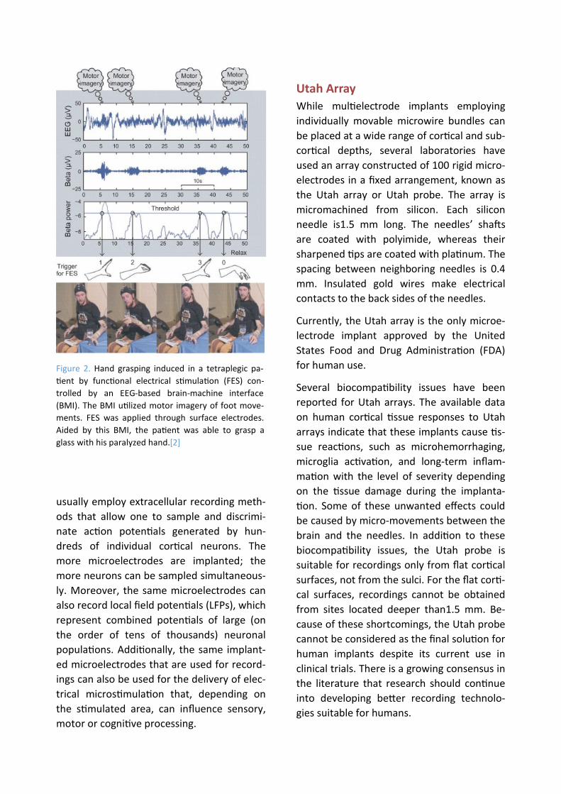
Figure 2. Hand grasping induced in a tetraplegic pa-
tient by functional electrical stimulation (FES) con-
trolled by an EEG-based brain-machine interface
(BMI). The BMI utilized motor imagery of foot move-
ments. FES was applied through surface electrodes.
Aided by this BMI, the patient was able to grasp a
glass with his paralyzed hand.[2]

tics of the stimulation, physiologic properties
of individual cells, geometry of the stimulus
field, geometry of the stimulated elements,
and possibly the underlying pathophysiology
of different disease states. No single mecha-
nism has emerged to account for the effect
of DBS in different brain regions and in differ-
ent diseases. However, it is becoming in-
creasingly clear that different types of cen-
tral nervous system (CNS) neurons possess
different types of ion channels that may have
different voltage-sensitive activation and in-
activation properties. Therefore, the effect of
DBS on neurons in different nuclei may be
quite different. It should be noted that low-
frequency stimulation appears to generally
excite nearby neurons, whereas high-
frequency stimulation can reduce local activi-
ty and thereby induce a reversible functional
lesion.
The idea of treating neurologic disorders
with chronic stimulation began to emerge in
the 1960s, but stimulation was largely used
for targeting surgical lesions. DBS has the
potential to provide substantial benefit for a
variety of neuropsychiatric conditions. Suc-
cess in Parkinson disease (PD) has spurred
development of DBS as a treatment for a
plethora of other conditions, some of which
have achieved widespread clinical adoption,
but most remain niche and/or investigation-
al. Since the introduction of DBS for Parkin-
son disease, more than 100,000 patients
worldwide have received the procedure.
Both stimulation targets have proven to be
highly effective at treating a range of PD
symptoms. Aside from PD, essential tremor
and dystonia are the most widely accepted
indications for DBS, with substantial bodies
of evidence supporting its efficacy. Other dis-
orders for which DBS shows promise include
chronic pain, obsessive–compulsive disorder
(OCD), epilepsy, and depression. More spec-
ulatively, addiction, anorexia, obesity, Tou-
Improving Multi-electrode Implants
While microwire arrays currently represent
the most practical solution for large-scale,
multi-area recordings from both cortical and
subcortical structures, there is ongoing re-
search into new technologies. One direction
of this research is aimed at minimizing the
micro-movements between the implant and
the brain that could result in tissue damage
and inflammation. One solution is to have
the implant float with the brain instead of
being anchored to the skull. In the design,
pioneered by Gualtierotti and Bailey in1968,
a lightweight implant is tethered by a flexible
cable. Several implementations of this idea
have been developed.
Deep brain stimulation (DBS)
Deep brain stimulation has already revolu-
tionized the clinical management of treat-
ment-resistant movement disorders and
offers novel treatment options for an in-
creasing range of neurological and psychiat-
ric illnesses. DBS is the implantation of elec-
trodes into deep brain regions for the pur-
pose of modulating neural function in order
to treat neurological/psychiatric conditions.
The electrodes are implanted using stereo-
tactic techniques and are attached to an im-
plantable pulse generator (IPG), which is typ-
ically placed subdermally below the clavicle.
A modern IPG contains a battery along with
electronic components that deliver electrical
stimulation and can be externally controlled
by patients or clinicians. Stimulation parame-
ters such as frequency, pulse width, and volt-
age need to be altered to achieve maximum
efficacy.
Electrical stimulation of the brain has been
shown to influence a variety of mechanisms
involved in neuronal function and signaling.
The sensitivity of different elements depends
on the amplitude and temporal characteris-

include integrated batteries; these can be primary cell designs with a battery that must last several years or rechargeable designs that have become more widely available re-cently, enabling transdermal recharging and hence longer IPG life. Battery life is highly dependent on the stimulation parameters required and, hence, the indication. Stimula-tion for PD requires less charge delivered than stimulation for dystonia, for example, resulting in dystonic patients usually requir-ing more frequent IPG replacement and/or recharging.
rette’s and Alzheimer’s are all being dis-
cussed and limited trials are being undertak-
en. Table 1 shows the anatomical targets be-
ing utilized for each indication.
Technology
Implant design has advanced substantially over recent years. During the 1980s, a typical DBS system consisted of an implanted radiof-requency receiver coil attached to elec-trodes, with an external battery device providing power transdermally via induction. Modern designs, however, universally
Indication Target(s) Status
Parkinson’s Subthalamic nucleus Internal globus pallidus Well-established
Essential tremor Ventral intermediate thalamus
Dystonia Internal globus pallidus
Parkinson’s Pedunculopontine nucleus Zona incerta
Not widely implement-ed, still under investigation
Essential tremor Zona incerta
Pain Periaqueductal and periventricular grey matter Ventral posterolateral and posteromedial thala-mus
obsessive–compulsive disorder. Anterior limb of internal capsule Medial thalamus
Tourette’s Internal globus pallidus
Epilepsy Hippocampus
Depression Subgenual cingulated Nucleus accumbens
Cluster headache Posterior hypothalamus
Addiction Nucleus accumbens Very limited investiga-tion
Anorexia Nucleus accumbens largely hypothetical
Obesity Nucleus accumbens
Alzheimer’s Fornix Ventromedial prefrontal cortex
Huntington’s Internal globus pallidus
Table 1. DBS indications.[3]

degradation in the patient’s condition or ad-
dressing specific symptoms not treated by
the first set of electrodes. In future, patients
may increasingly benefit from implantation
of several electrodes with the intent of
treating multiple symptoms at once or syner-
gistically treating one symptom via multiple
mechanisms.
A major disadvantage of DBS as currently im-
plemented is the necessity of inserting an
electrode through the scalp, skull, and brain,
with all the hazards this entails. Deep brain
stimulation may cause some risks and poten-
tial side effects. These stimulations may bring
about brain hemorrhage including strokes,
infection, headaches and worsening mental
or emotional status. Also during stimulations
the patient may face side effects such as
temporary tingling in the face or limbs, a
feeling of pulling in muscles, speech or vision
problems and loss of balance. Beside these
disadvantages and side effects listed upper,
the surgery must be repeated every three to
five years in order to replace the battery in
the device.
Neuralink
As already dicussed, brain-machine interfac-
es (BMIs) have the potential to help people
with a wide range of clinical disorders. For
example,researchers have demonstrated hu-
man neuroprosthetic control of computer
cursors, robotic limbs, and speech synthesiz-
ers using no more than 256 electrodes.
While these successes suggest that high fi-
delity information transfer between brains
and machines is possible, development of
BMI has been critically limited by the inability
to record from large numbers of neurons.
Noninvasive approaches can record the aver-
age of millions of neurons through the skull,
but this signal is distorted and nonspecific.
Invasive electrodes placed on the surface of
the cortex can record useful signals, but they
All modern IPGs contain a radiofrequency
antenna so that external programming devic-
es can be used to set the stimulation param-
eters, as well as for monitoring impedance
and editing stored data. Typically, one pro-
gramming device is designed for clinicians to
use and features the full range of controls,
and another is given to patients and features
fewer settings, often restricted by settings
that can be altered by the clinician program-
ming device. Increasingly, these devices are
taking the form of “apps” on consumer-
grade mobile devices such as smartphones
and tablets, instead of purpose-built devices.
Most IPGs use proprietary radio communica-
tion protocols, although recently consumer-
grade protocols such as Bluetooth are being
utilized in order to facilitate interoperability
of devices.
Charge is delivered via transcranial elec-
trodes, which typically feature multiple elec-
trode contacts. During programming, the ac-
tive contact can be changed, delivering ener-
gy to slightly different locations, enabling
limited fine-tuning of the stimulation loca-
tion. A major recent development is the im-
plementation of ‘directional’ or ‘segmented’
electrodes – these consist of multiple sepa-
rate electrode contacts arranged around the
circumference of the electrode, which can
deliver the charge simultaneously. This ena-
bles more precise control over the volume of
neural tissue that is activated, thereby allow-
ing for minor deviations from the intended
implant trajectory to be corrected and for
small variations in individual anatomy to be
compensated for.
Improvements may be found in simultaneous
stimulation of multiple targets too. Currently,
the majority of patients receive stimulation
targeting just a few sites, with electrodes
placed unilaterally or bilaterally, but addi-
tional electrodes are occasionally implanted
with the intent of managing future

a high-bandwidth BMI, while taking ad-
vantage of the properties of thin-film devic-
es, Neuralink developed a robotic approach,
where large numbers of fine and flexible pol-
ymer probes are efficiently and independent-
ly inserted across multiple brain regions.
Neuralink implantation devices are small,
flexible, made of biocompatible materials
and has airtight packaging that will minimize
brain immune response and make the device
last for a longer period of time in the body.
These devices are able to stimulate and rec-
ord neurons simultaneously which is an im-
portant and essential factor for highly func-
tioning BMI devices.
Threads
Neuralink threads bring about many ad-
vantages in compare with old electrodes.
These threads are flexible which are less like-
ly to damage brain than other materials be-
ing used in brain-machine interfaces. Beside
that, these threads bring about the possibil-
ity of transferring a higher volume of data.
Neuralink notes that the system could in-
clude “as many as 3,072 electrodes per array
distributed across 96 threads.” The threads
are 4 to 6 μm in width, which makes them a
tenth of a human hair. Neuralink has devel-
oped a custom process to fabricate minimal-
ly displacive neural probes that employ a va-
riety of biocompatible thin film materials.
The main substrate and dielectric used in
these probes is polyimide, which encapsu-
lates a gold thin film trace. Each thin film ar-
ray is composed of a “thread” area that fea-
tures electrode contacts and traces and a
“sensor” area where the thin film interfaces
with custom chips that enable signal amplifi-
cation and acquisition.
Neuralink have fabricated threads ranging
from 5 to 50 µm in width that incorporate
recording sites of several geometries (fig 3).
are limited in that they average the activity
of thousands of neurons and cannot record
signals deep in the brain. Most BMI’s have
used invasive techniques because the most
precise readout of neural representations
requires recording single action potentials
from neurons in distributed, functionally-
linked ensembles. Beside that, the central
problem of interacting with AI which is band-
width remains still.
Microelectrodes are the gold-standard tech-
nology for recording action potentials, but
there has not been a clinically translatable
microelectrode technology for large-scale
recordings. This would require a system with
material properties that provide high bio-
compatibility, safety, and longevity. Moreo-
ver, this device would also need a practical
surgical approach and high-density, low-
power electronics to ultimately facilitate fully
-implanted wireless operation.
Most devices for long-term neural recording
are arrays of electrodes made from rigid
metals or semiconductors. While rigid metal
arrays facilitate penetrating the brain, the
size, Young’s modulus and bending stiffness
mismatches between stiff probes and brain
tissue can drive immune responses that limit
the function and longevity of these devices.
Furthermore, the fixed geometry of these
arrays constrains the populations of neurons
that can be accessed, especially due to the
presence of vasculature. An alternative ap-
proach is to use thin, flexible multi-electrode
polymer probes. The smaller size and in-
creased flexibility of these probes should
offer greater biocompatibility. However, a
drawback of this approach is that thin poly-
mer probes are not stiff enough to directly
insert into the brain; their insertion must be
facilitated by stiffeners injection or other ap-
proaches, all of which are quite slow.
To satisfy the functional requirements for

Since the individual gold electrode sites have
small geometric surface areas (fig.1C), Neu-
ralink use surface modifications to lower the
impedance for electrophysiology and in-
crease the effective charge-carrying capacity
of the interface (fig.1D).
It should be noted that to keep the electron-
ics package small, a novel alignment and flip-
chip bonding process was developed. This
alignment and bonding process was key to
creating a package containing 3,072 channels
in a (23 × 18.5) mm2 footprint.
Robot
Thin-film polymers have previously been used for electrode probes, but their low
Figure 3: Our novel polymer probes. A. “Linear Edge” probes, with 32 electrode contacts spaced by 50 µm. B.
“Tree” probes with 32 electrode contacts spaced by 75 µm. C. Increased magnification of individual electrodes for
the thread design in panel A, emphasizing their small geometric surface area. D. Distribution of electrode impedanc-
es (measured at 1 kHz) for two surface treatments: PEDOT (n = 257) and IrOx (n = 588). [1]
bending stiffness complicates insertions.
Neuralink has developed a robotic insertion
approach for inserting flexible probes, allow-
ing rapid and reliable insertion of large num-
bers of polymer probes targeted to avoid
vasculature and record from dispersed brain
regions. The robot’s insertion head is mount-
ed on 10 µm globally accurate, 400 mm ×
400 mm × 150 mm travel three-axis stage,
and holds a small, quick-swappable, “needle-
pincher” assembly (fig.4, fi g.5A).
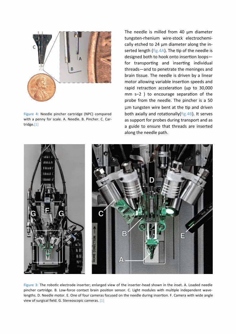
Figure 3: The robotic electrode inserter; enlarged view of the inserter-head shown in the inset. A. Loaded needle
pincher cartridge. B. Low-force contact brain position sensor. C. Light modules with multiple independent wave-
lengths. D. Needle motor. E. One of four cameras focused on the needle during insertion. F. Camera with wide angle
view of surgical field. G. Stereoscopic cameras. [1]
Figure 4: Needle pincher cartridge (NPC) compared
with a penny for scale. A. Needle. B. Pincher. C. Car-
tridge.[1]
The needle is milled from 40 µm diameter
tungsten-rhenium wire-stock electrochemi-
cally etched to 24 µm diameter along the in-
serted length (fig.4A). The tip of the needle is
designed both to hook onto insertion loops—
for transporting and inserting individual
threads—and to penetrate the meninges and
brain tissue. The needle is driven by a linear
motor allowing variable insertion speeds and
rapid retraction acceleration (up to 30,000
mm s−2 ) to encourage separation of the
probe from the needle. The pincher is a 50
µm tungsten wire bent at the tip and driven
both axially and rotationally(fig.4B). It serves
as support for probes during transport and as
a guide to ensure that threads are inserted
along the needle path.

to facilitate faster and more reliable manu-
facturing; it can be built five times faster
than System B with better yields.
An ethernet-connected base station converts
the data streams from these systems into
multicast 10G ethernet UDP packets allowing
downstream users to process the data in a
variety of ways, e.g. visualizing the data in
real-time or writing it to disk. Each base sta-
tion can connect to up to three implants sim-
ultaneously. These devices are further sup-
ported by a software ecosystem that allows
for plug and play usability with zero configu-
ration: neural data begins streaming auto-
matically when a cable is connected.
N1 System
Neuralink is developing a custom chip that is
better able to read, clean up, and amplify
signals from the brain. Right now, it can only
transmit data via a wired connection (it uses
USB-C), but ultimately the goal is to create a
system that can work wirelessly. This wire-
less goal will be embodied in a product called
the “N1 sensor,” designed to be embedded
inside a human body and transmit its data
wirelessly. It may read fewer neurons than
the current USB-based prototype. Four of
these sensors will be planted, three in motor
areas and one in a somatosensory area. It
will connect wirelessly to an external device
mounted behind the ear, which will contain
the only battery and will be controlled
through an iPhone app.
N1 system is considerably physically small (4×5mm), consumes low power and highly configurable. N1 has 1024 channels and are capable to record signals and stimulate neu-rons simultaneously. This chip consists of on-chip spike detection. N1 has three key inno-vation in its self: 1.analogue pixels, 2.on chip spike detection 3.stimulation on every chan-nel.
The inserter head also holds an imaging stack
(fig.5E–G) used for guiding the needle into
the thread loop, insertion targeting, live in-
sertion viewing, and insertion verification. In
addition, the inserter head contains six inde-
pendent light modules, each capable of inde-
pendently illuminating with 405 nm, 525 nm
and 650 nm or white light (fig.5C). The 405
nm illumination excites fluorescence from
polyimide and allows the optical stack and
computer vision to reliably localize the (16 ×
50) µm 2 thread loop and execute sub-
micron visual servoing to guide, illuminated
by 650 nm the needle through it. Stereoscop-
ic cameras, software based monocular ex-
tended depth of field calculations, and illumi-
nation with 525 nm light allow for precise
estimation of the location of the cortical sur-
face. With this system, neuralink have
demonstrated an average of 87.1 ± 12.6 %
(mean ± s.d.) insertion success rate over 19
surgeries.
Electronics
Chronic recording from thousands of elec-
trode sites presents significant electronics
and packaging challenges. The density of re-
cording channels necessitates placing the
signal amplification and digitization stack
within the array assembly, otherwise the ca-
ble and connector requirements would be
prohibitive. This recording stack must ampli-
fy small neural signals (<10 µV RMS) while
rejecting out-of-band noise, sample and dig-
itize the amplified signals, and stream out
the results for real-time processing—all using
minimal power and size.
Neuralink have built two configurations, one
1 ,536 channel recording system (System A)
and another 3,072 channel recording system
(“System B”). System B was designed to max-
imize channel density and is used for applica-
tions that demand extremely high channel
count. In contrast, System A was designed

Figure 6: 1. The inserter approaches the brain proxy with a thread. i. needle and cannula. ii. previously inserted
thread. 2. Inserter touches down on the brain proxy surface. 3. Needle penetrates tissue proxy, advancing the thread
to the desired depth. iii. inserting thread. 4. Inserter pulls away, leaving the thread behind in the tissue proxy. iv.
Inserted thread.[1]
verted and digitized to zero and ones by on-chip analogue to digital converters. Since spikes are often critical for certain BMI tasks, currently there are several different methods for detecting spikes such as thresholding and principle component analysis. Neuralink method is by directly characterizing the shape. This method reveal more information
than similar methods.
Discussion
Neuralink have described a BMI with high-channel count and single-spike resolution. It is based on flexible polymer probes, a robotic insertion system, and custom low-power
Analogue pixel
We need to amplify and filter analogue neu-
rosignals before we can convert them into
digital bits and this key point is the actual
importance of analogue pixels. We are will-
ing to have one analogue pixel per electrode
so that we can configure them independent-
ly. So in case of N1 we will have 1024 ana-
logue pixels. This division take up a signifi-
cant space on the chip.
On-chip spike detection
Once the signals are amplified, they are con-

such a device, it is plausible to imagine that a
patient with spinal cord injury could dexter-
ously control a digital mouse and keyboard.
When combined with rapidly improving spi-
nal stimulation techniques, in the future this
approach could conceivably restore motor
function. High-bandwidth neural interfaces
should enable a variety of novel therapeutic
possibilities.
Refrence
[1] Musk, E. (2019). An integrated brain-
machine interface platform with thousands
of channels. Journal of medical Internet re-
search, 21(10), e16194.
[2] Lebedev, M. A., & Nicolelis, M. A. (2017).
Brain-machine interfaces: From basic science
to neuroprostheses and neurorehabilita-
tion. Physiological reviews.
[3] Pycroft, L., Stein, J., & Aziz, T. (2018).
Deep brain stimulation: An overview of histo-
ry, methods, and future developments. Brain
and Neuroscience Advances, 2,
2398212818816017.
[4] Perlmutter, J. S., & Mink, J. W. (2006).
Deep brain stimulation. Annu. Rev. Neuro-
sci., 29, 229-257.
[5] Guenther, F. H., Brumberg, J. S., Wright,
E. J., Nieto-Castanon, A., Tourville, J. A.,
Panko, M., ... & Ehirim, P. (2009). A wireless
brain-machine interface for real-time speech
synthesis. PloS one, 4(12), e8218.
[6] Cusanovich, D. A., Daza, R., Adey, A., Plin-
er, H. A., Christiansen, L., Gunderson, K. L., ...
& Shendure, J. (2015). Multiplex single-cell
profiling of chromatin accessibility by combi-
natorial cellular indexing. Science, 348(6237),
910-914.
[7] Neuralink (16 jul 2019) Neuralink Launch
Event Retrieved from http://https://
www.youtube.com/watch?v=r-vbh3t7WVI
electronics. This system serves two main pur-
poses: it is a research platform for use in ro-
dents and serves as a prototype for future
human clinical implants. The ability to quickly
iterate designs and testing in rodents allows
for the rapid refinement of devices, manu-
facturing processes, and software. Because it
is a research platform, the system uses a
wired connection to maximize the bandwidth
for raw data streaming. This is important for
performance assessments and crucial for the
development of signal processing and decod-
ing algorithms.
In contrast, the clinical devices that will de-
rive from this platform will be fully implanta-
ble—which requires hermetic packaging—
and have on-board signal compression, re-
duced power consumption, wireless power
transmission, and data telemetry through
the skin without percutaneous leads.
Modulating neural activity will be an im-
portant part of next-generation clinical brain-
machine interfaces, for example to provide a
sense of touch or proprioception to neuro-
prosthetic movement control.
This BMI system has several advantages over
previous approaches. The size and composi-
tion of the thin-film probes are a better
match for the material properties of brain
tissue than commonly used silicon probes,
and therefore may exhibit enhanced biocom-
patibility. Also, the ability to choose where
our probes are inserted, including into sub-
cortical structures, allows us to create cus-
tom array geometries for targeting specific
brain regions while avoiding vasculature. This
feature is significant for creating a high-
performance BMI, as the distribution of elec-
trodes can be customized depending on the
task requirements.
While significant technological challenges
must be addressed before a high-bandwidth
device is suitable for clinical application, with