Neural network-based sensorless direct power control of...
12
ELECTRICAL ENGINEERING Neural network-based sensorless direct power control of permanent magnet synchronous motor Mahdi Zolfaghari a , Seyed Abbas Taher b, * , David Vindel Munuz c a Department of Electrical Engineering, Amirkabir University, Tehran, Iran b Department of Electrical Engineering, University of Kashan, Kashan, Iran c Department of Energy and Environment, Chalmers University of Technology, Sweden Received 28 January 2015; revised 11 November 2015; accepted 8 January 2016 Available online 1 February 2016 KEYWORDS PMSM; Direct power control; Artificial neural network; MRAS Abstract In this paper, a sensorless permanent magnet synchronous motor (PMSM) drive was presented based on direct power control (DPC) technique. To estimate the rotor’s position and speed of PMSM, a drastic sensorless strategy was developed according to artificial neural network (ANN) to reduce the cost of the drive and enhance the reliability. The proposed sensorless scheme was an innovative model reference adaptive system (MRAS) speed observer for DPC control PMSM drives. The suggested MRAS speed observer employed the current model as an adaptive model. The ANN was then designed and trained online by employing a back propagation network (BPN) algorithm. Performance of the proposed strategy was adopted using simulation analysis. The results showed the fast dynamic response, low ripples in motor’s currents, power, and electromag- netic torque, as well as good performance in tracking speed and power references. Ó 2016 Faculty of Engineering, Ain Shams University. Production and hosting by Elsevier B.V. This is an open access article under the CC BY-NC-ND license (http://creativecommons.org/licenses/by-nc-nd/4.0/). 1. Introduction Recently, PMSMs have received more interest, since they are more efficient and cost-effective and have an appropriate speed control range and reduced maintenance requirements [1,2]. For PMSM drives, several control strategies have been reported in the literature [1,3]. The well-known technique, direct torque control (DTC), is now being adopted by the industry. However, DTC still has some drawbacks such as rel- atively high ripples in flux and torque [4,5]. Also, the switching frequency of the inverter is not constant for a DTC without vector control method and changes with rotor speed, load tor- que, and bandwidth of the two hysteresis controllers. Direct power control (DPC) is a control technique which, without using current loops, directly selects output voltage vector states based on the power and flux errors using hysteresis controllers. In this respect, it is the same as DTC. Similar to DTC, DPC is a stator flux-based control technique with the advantages of robustness and fast control [6]. DPC has the following advan- tages: simpler voltage and power estimation algorithm, easy implementation of the unbalanced and distorted line voltage compensation to obtain sinusoidal currents (low THD), * Corresponding author at: Department of Electrical Engineering, University of Kashan, 6 km Ravand Road, Kashan, Iran. Tel./fax: +98 3615559930. E-mail address: [email protected] (S.A. Taher). Peer review under responsibility of Ain Shams University. Production and hosting by Elsevier Ain Shams Engineering Journal (2016) 7, 729–740 Ain Shams University Ain Shams Engineering Journal www.elsevier.com/locate/asej www.sciencedirect.com http://dx.doi.org/10.1016/j.asej.2016.01.002 2090-4479 Ó 2016 Faculty of Engineering, Ain Shams University. Production and hosting by Elsevier B.V. This is an open access article under the CC BY-NC-ND license (http://creativecommons.org/licenses/by-nc-nd/4.0/).
Transcript of Neural network-based sensorless direct power control of...

Ain Shams Engineering Journal (2016) 7, 729–740
Ain Shams University
Ain Shams Engineering Journal
www.elsevier.com/locate/asejwww.sciencedirect.com
ELECTRICAL ENGINEERING
Neural network-based sensorless direct power
control of permanent magnet synchronous motor
* Corresponding author at: Department of Electrical Engineering,
University of Kashan, 6 km Ravand Road, Kashan, Iran. Tel./fax:
+98 3615559930.
E-mail address: [email protected] (S.A. Taher).
Peer review under responsibility of Ain Shams University.
Production and hosting by Elsevier
http://dx.doi.org/10.1016/j.asej.2016.01.0022090-4479 � 2016 Faculty of Engineering, Ain Shams University. Production and hosting by Elsevier B.V.This is an open access article under the CC BY-NC-ND license (http://creativecommons.org/licenses/by-nc-nd/4.0/).
Mahdi Zolfaghari a, Seyed Abbas Taher b,*, David Vindel Munuz c
aDepartment of Electrical Engineering, Amirkabir University, Tehran, IranbDepartment of Electrical Engineering, University of Kashan, Kashan, IrancDepartment of Energy and Environment, Chalmers University of Technology, Sweden
Received 28 January 2015; revised 11 November 2015; accepted 8 January 2016Available online 1 February 2016
KEYWORDS
PMSM;
Direct power control;
Artificial neural network;
MRAS
Abstract In this paper, a sensorless permanent magnet synchronous motor (PMSM) drive was
presented based on direct power control (DPC) technique. To estimate the rotor’s position and
speed of PMSM, a drastic sensorless strategy was developed according to artificial neural network
(ANN) to reduce the cost of the drive and enhance the reliability. The proposed sensorless scheme
was an innovative model reference adaptive system (MRAS) speed observer for DPC control
PMSM drives. The suggested MRAS speed observer employed the current model as an adaptive
model. The ANN was then designed and trained online by employing a back propagation network
(BPN) algorithm. Performance of the proposed strategy was adopted using simulation analysis. The
results showed the fast dynamic response, low ripples in motor’s currents, power, and electromag-
netic torque, as well as good performance in tracking speed and power references.� 2016 Faculty of Engineering, Ain Shams University. Production and hosting by Elsevier B.V. This is an
open access article under the CC BY-NC-ND license (http://creativecommons.org/licenses/by-nc-nd/4.0/).
1. Introduction
Recently, PMSMs have received more interest, since they aremore efficient and cost-effective and have an appropriate speed
control range and reduced maintenance requirements [1,2].For PMSM drives, several control strategies have been
reported in the literature [1,3]. The well-known technique,direct torque control (DTC), is now being adopted by theindustry. However, DTC still has some drawbacks such as rel-
atively high ripples in flux and torque [4,5]. Also, the switchingfrequency of the inverter is not constant for a DTC withoutvector control method and changes with rotor speed, load tor-que, and bandwidth of the two hysteresis controllers. Direct
power control (DPC) is a control technique which, withoutusing current loops, directly selects output voltage vector statesbased on the power and flux errors using hysteresis controllers.
In this respect, it is the same as DTC. Similar to DTC, DPC isa stator flux-based control technique with the advantages ofrobustness and fast control [6]. DPC has the following advan-
tages: simpler voltage and power estimation algorithm, easyimplementation of the unbalanced and distorted line voltagecompensation to obtain sinusoidal currents (low THD),

730 M. Zolfaghari et al.
excellent dynamics, and no need for coordinatetransformation [7].
Basically, DPC is applied to generators. In [8], the conven-
tional DTC scheme for inducing motor drives was extended todirectly control the active power (DPC) delivered to an activeload by a wind turbine driven squirrel cage induction genera-
tor (SCIG). The SCIG was interfaced to the load through anAC–DC converter (PWM rectifier). The goal of this controlsystem was to maintain the DC bus voltage at a constant value
independent from the variations of the load. In [9], for a dou-bly fed induction generator (DFIG), an algorithm was devel-oped for the independent control of active and reactivepowers with high dynamic response. The instantaneous switch-
ing state of the rotor side converter (RSC) was determinedbased on the active and reactive powers measured in the statorcircuit. Measurements were carried out in one terminal of the
machine, whereas the switching action was performed inanother terminal. The directly controlled quantities were thestator active and reactive powers. A new adaptive control
strategy for a wind energy conversion system based on a per-manent magnet synchronous generator and a pulse-widthmodulated current source converter were introduced in [10].
This conversion system was a good alternative because of itshigh efficiency and reliability. Electrolytic capacitors werenot required in this type of converter and the voltage in theDC-link as well as the generated reactive power could be
dynamically modified according to wind velocity, being evennegative if required. However, it was challenging from the con-trol and stability standpoints [11,12].
In [13], a combined vector and direct power control(CVDPC) was proposed for the RSC of DFIGs. The control
ANN-BPN-MRAS based
Speed Controller
∑
∑
1K
C
PI
2K
∫
3-phase Supply
rje φ
θ
*slω
*eT*ω
ω
*dsi
*siα
*siβ
Figure 1 Overall diagram of sensorless control of PMSM drive
system was based on a direct current control by selectingappropriate voltage vectors from a switching table. In fact,the CVDPC enjoyed from the benefits of vector control (VC)
and DPC in a compacted control system. Its benefits, in com-parison with VC, included fast dynamic response, robustnessagainst variation of machine parameters, lower computation,
and simple implementation [14–16]. A direct rotor currentmode control (CMC) was suggested in [17] for the RSC ofinduction generators, which was aimed to improve the tran-
sient response in relation to the dynamic performance achievedby the conventional (indirect) CMC. A simple method forachieving the predictive direct power control (PDPC) forDFIG-based wind energy conversion systems was proposed
in [18]. This approach was able to operate at low switching fre-quency and provide excellent steady-state and dynamic perfor-mances, which were useful for high-power wind energy
applications. Three vectors were selected and applied duringone control period to reduce both active and reactive powerripples. Compared to the prior three-vectors-based art using
two switching tables, the approach only needed one unifiedswitching table to obtain the three vectors [19,20]. Nowadays,it has been tried to employ DPC to control electrical motors
instead of DTC techniques due to the problems of torque esti-mation and dependence on motor parameters in DTC. Thus,DPC technique relishes all the advantages of DTC such as fastdynamics and implementation ease without having its
problems.In machine learning and cognitive science, artificial neural
networks (ANNs) are a family of statistical learning algo-
rithms inspired by biological neural networks (the central ner-vous systems of animals, in particular the brain) and are used
∑∑
∑
HysteresisController
PWMInverter
DChopper
abctoαβ
dsvqsv
dsiqsi
*ai
*bi
*ci
ai
bi
ci−
−
−+
+
+
PMSM
using the proposed ANN-BPN-MRAS based speed estimator.

Figure 2 The proposed speed estimator based on MRAS including an ANN.
Neural network-based sensorless direct power control 731
to estimate or approximate functions that can depend on alarge number of inputs and are generally unknown [22]. ANNs
are generally presented as systems of interconnected ‘‘neurons”which can compute values from inputs and are capable ofmachine learning as well as pattern recognition, thanks to theiradaptive nature. Like other machine learning methods – sys-
tems that learn from data, neural networks have been usedto solve a wide variety of tasks that are hard to solve usingordinary rule-based programming, including computer vision
and speech recognition.In the present study, a sensorless PMSM drive was pre-
sented based on DPC technique, in which the motor speed
was estimated using an ANN-based MRAS speed estimator.The proposed control scheme was a model reference adaptivesystem (MRAS) speed observer for DPC control PMSMdrives. The suggested MRAS speed observer employed the cur-
rent model as an adaptive model. The ANN was then designedand trained online by employing a back propagation network(BPN) algorithm. The simulation and experimental results
were presented to verify the performance of the proposedPMSM drive.
2. Dynamic model of PMSM
Electrical drives with PMSMs have found a wide implementa-tion in different fields of the present day society, whereas vec-
tor control has become the state of the art method of the a.c.
Figure 3 ANN pattern fo
drive control. Drive structure usually involves an a.c. machineequipped with sensors, a microcontroller, and a PWM inver-
ter. Based on data received from position (hmeans) and currentsensors, microcontroller generates pulse width modulated volt-age patterns, which, amplified by PWM inverter, drive PMSM.
Model of a sinusoidal PMSM can be described in the rotor
d–q reference frame by the following equations [1,12]:
vd ¼ Rid þ Ld
diddt
� LqPpxiq
vq ¼ Riq þ Lq
diqdt
þ LdPpxid þ PpxkPM
Tm ¼ 3
2Pp½kPMiq þ ðLd � LqÞidiq�
dxdt
¼ 1
JðTm � TL � FxÞ
dhdt
¼ x
ð1Þ
where vd; vq are the stator voltages in the rotor reference frame,
id; iq are the stator currents in the rotor reference frame, R is
the stator phase resistance, Ld;Lq are the machine inductances,
respectively, along direct quadrature axis, Pp is the number of
motor pole pairs, kPM is the flux generated by permanent mag-nets, Tm is the electromagnetic torque, TL is the load torque, F
is the viscous friction coefficient, J is the moment of inertia ofall rotating masses, x is the instantaneous angular speed, and his the instantaneous angular position.
r rotor flux estimation.

Table 1 On and off states and the corresponding outputs of a three-phase VSI.
State Sa Sb Sc ua=Udc ub=Udc uc=Udc uab ubc uca ua=Udc ub=Udc
u0 0 0 0 0 0 0 0 0 0 0 0
u5 0 0 1 �1/3 �1/3 2/3 0 �1 1 �1/3 �1=ffiffiffi3
pu3 0 1 0 �1/3 2/3 �1/3 �1 1 0 �1/3 1=
ffiffiffi3
pu4 0 1 1 �2/3 1/3 1/3 �1 0 1 �2/3 0
u1 1 0 0 2/3 �1/3 �1/3 1 0 �1 2/3 0
u6 1 0 1 1/3 �2/3 1/3 1 �1 0 1/3 �1=ffiffiffi3
pu2 1 1 0 1/3 1/3 �2/3 0 1 �1 1/3 1=
ffiffiffi3
pu7 1 1 1 0 0 0 0 0 0 0 0
732 M. Zolfaghari et al.
3. Proposed PMSM control scheme
3.1. Speed estimation
A complete block diagram of the proposed ANN-MRAS-
based sensorless control of PMSM drive is shown in Fig. 1.MRAS scheme is less complex and more effective. The MRASapproach uses two models. The model that does not involvethe quantity to be estimated is considered the reference model.
The model that has the quantity to be estimated is consideredthe adaptive model (or adjustable model). The output of theadaptive model is compared to that of the reference model
and the difference is used to drive a suitable adaptive mecha-nism whose output is the quantity to be estimated (the rotorspeed). The adaptive mechanism should be designed to assure
Figure 4 Response of the speed PMSM motor: (a) dc link cu
the stability of the control system. The MRAS uses redun-dancy of two-machine model of different structures that esti-
mate the same state variables. Both models are referred to inthe stationary reference frame and the output of a referencemodel is compared to the output of an adjustable or adaptive
model until the errors between the two models vanish to zero.With the correct value of rotor speed, the fluxes determinedfrom the two models should match. An adaptation algorithm
can be used to tune the speed value until the two flux valuesmatch.
In MRAS technique, some state variables, xd; xq (e.g. rotor
flux-linkage component, ed; eq, etc.) of the machine (obtained
by measured quantities, e.g. stator voltages and currents) areestimated in a reference model and then compared with thestate variables x̂d; x̂q estimated by an adaptive model. The
rrent control, (b) DTC, and (c) the proposed DPC scheme.

Figure 5 Response of the torque of PMSM motor: (a) dc link current control, (b) DTC, and (c) the proposed DPC scheme.
Neural network-based sensorless direct power control 733
difference between these state variables is then formulated as a
speed tuning signal (e), which then becomes an input for theadaptation mechanism and outputs the estimated rotor speed(x̂). Speed estimator using ANN is a part of a MRAS, where
ANN takes the role of the adaptive model. ANN contains theadjustable and constant weights and the adjustable weights areproportional to the rotor speed. The adjustable weights arechanged by the error between the outputs of the reference
and adaptive model. Fig. 2 shows the MRAS-based speed esti-mation scheme, which contains an ANN with BPN adaptationtechnique. Outputs of the reference model are the rotor flux
linkage components in stationary reference frame, as givenby [1,12]:
wdr ¼Lr
Lm
Zðvds � RsidsÞdt� Lsids
� �wqr ¼
Lr
Lm
Zðvqs � RsiqsÞdt� Lsiqs
� � ð2Þ
These two equations do not contain the rotor speed anddescribe the reference model. The equations of adaptive modelare given by [1,12]
bwdr ¼ 1
Tr
ZðLmids � bwdr � xrTr
bwqrÞdt
bwqr ¼ 1
Tr
ZðLmiqs � bwqr � xrTr
bwdrÞdtð3Þ
It is possible to implement Eqs. (3) and (4) by a two-layerANN containing weights, w1ð¼ 1� cÞ;w2ð¼ xrcTr ¼ xrTÞand w3ð¼ cLmÞ; where c ¼ T=Tr. T;Tr are sampling time and
rotor time constant. The variable ANN weight w2 is propor-
tional to the rotor speed. Using the backward differencemethod, the equation of adaptive model is given as follows:
bwdrðkÞ ¼ w1bwdrðk� 1Þ � w2
bwqrðk� 1Þ þ w3idsðk� 1ÞbwqrðkÞ ¼ w1bwqrðk� 1Þ þ w2
bwdrðk� 1Þ þ w3iqsðk� 1Þð4Þ
which gives the value of rotor flux at the kth sampling instant.These equations can be visualized by the very simple two-layerANN shown in Fig. 3 [22]. The back propagation algorithm
[23] is used in the layered feed-forward ANN. This means thatthe artificial neurons are organized in layers, their signals aresent ‘‘forward”, and then the errors are propagated back-
wards. The network receives inputs by neurons in the inputlayer and the output of the network is given by the neuronson an output layer.
3.2. Power control
The main issue in DPC is the correct power calculation. If thestator winding loss and core loss are small enough to beneglected, the input electrical power is the same as the electro-
magnetic power. If the rotational losses are also small and neg-ligible, the electrical input power can be approximated as themechanical output power. Thus
Pin ffi Pe ¼ Pout ð5Þwhere Pin;Pe, and Pout represent the electrical input power,electromagnetic power, and mechanical output power,

Figure 6 Response of the power of PMSM motor: (a) dc link current control, (b) DTC, and (c) the proposed DPC scheme.
734 M. Zolfaghari et al.
respectively. The mechanical input power can be expressed asfollows:
Pout ¼ Tem
xr
Pð6Þ
The electromagnetic torque of a PMSM in the syn-
chronously rotating d–q reference frame can be expressed asfollows [21]:
Tem ¼ 3P
4
dLds
dheisdþdwrd
dhe�wsq
� �isdþ dLdq
dheisqþ
dwrq
dhe�wsd
� �isq
� �ð7Þ
Substituting the torque in (6) by (7) results in the output
power as
Pout ¼ 3xr
4
dLds
dheisdþdwrd
dhe�wsq
� �isdþ dLdq
dheisqþ
dwrq
dhe�wsd
� �isq
� �ð8Þ
where wsd ¼ Lsdisd þ wrd, wsq ¼ Lsqisq þ wrq, he is the rotor elec-trical angle, P is the number of poles, isd; isq are d and q-axes
currents, Lds;Lqs are d and q-axes stator inductances, and
wrd;wrq;wsd are d and q-axes rotor and stator flux linkages,
respectively.
3.3. Hysteresis controller and PWM inverter
Among the various PWM techniques, the hysteresis band cur-rent control is used very often because of its implementation
simplicity. Also, besides fast response current loop, the methoddoes not need any knowledge of load parameters. However,the current control with a hysteresis band has the disadvantage
that the PWM frequency varies within a band, because peak-to-peak current ripple is required to be controlled at all pointsof the fundamental frequency wave. The method of adaptive
hysteresis-band current control PWM technique, in whichthe band can be programmed as a function of load to optimizethe PWM performance, was described in [3]. The basic imple-mentation of hysteresis current control is based on deriving the
switching signals from the comparison of the current errorwith a fixed tolerance band. This control is based on the com-parison of the actual phase current with the tolerance band
around the reference current associated with that phase. Onthe other hand, this type of band control is negatively affectedby the phase current interactions which is typical in three-
phase systems, which is mainly due to the interference betweenthe commutations of the three phases, since each phase currentnot only depends on the corresponding phase voltage, but is
also affected by the voltage of the other two phases. Depend-ing on load conditions, switching frequency may vary duringthe fundamental period, resulting in irregular inverteroperation. In [4], the authors proposed a new method that
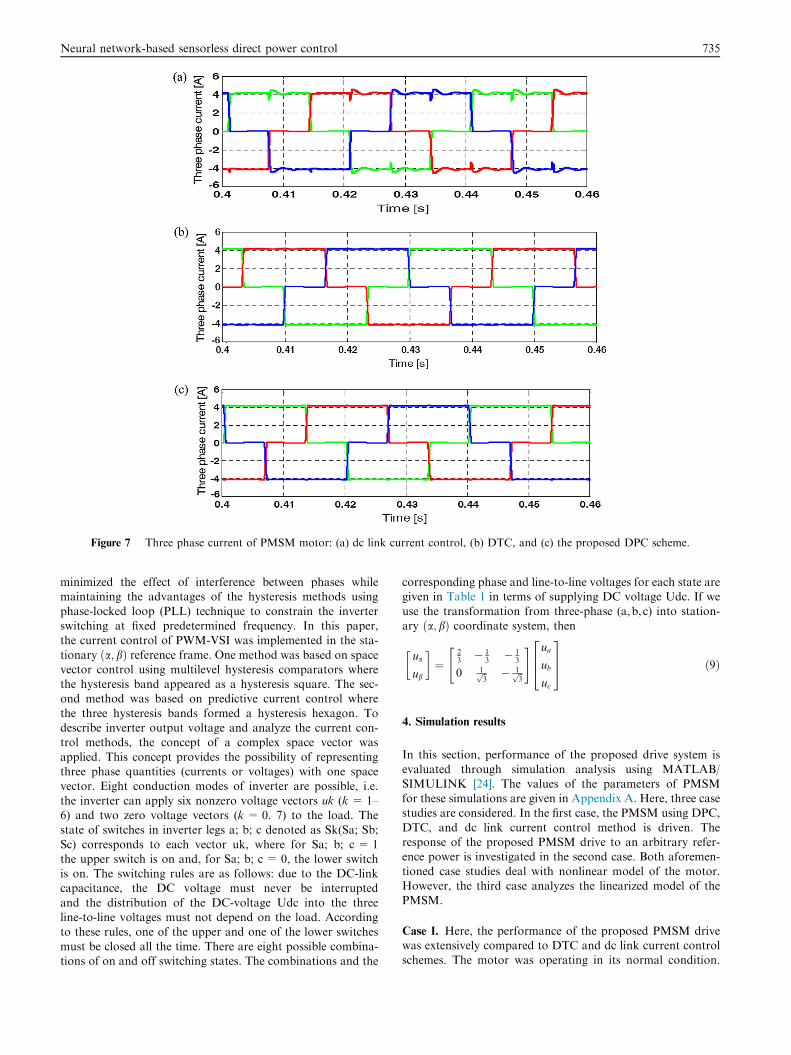
Figure 7 Three phase current of PMSM motor: (a) dc link current control, (b) DTC, and (c) the proposed DPC scheme.
Neural network-based sensorless direct power control 735
minimized the effect of interference between phases whilemaintaining the advantages of the hysteresis methods using
phase-locked loop (PLL) technique to constrain the inverterswitching at fixed predetermined frequency. In this paper,the current control of PWM-VSI was implemented in the sta-
tionary ða; bÞ reference frame. One method was based on spacevector control using multilevel hysteresis comparators wherethe hysteresis band appeared as a hysteresis square. The sec-ond method was based on predictive current control where
the three hysteresis bands formed a hysteresis hexagon. Todescribe inverter output voltage and analyze the current con-trol methods, the concept of a complex space vector was
applied. This concept provides the possibility of representingthree phase quantities (currents or voltages) with one spacevector. Eight conduction modes of inverter are possible, i.e.
the inverter can apply six nonzero voltage vectors uk (k = 1–6) and two zero voltage vectors (k = 0. 7) to the load. Thestate of switches in inverter legs a; b; c denoted as Sk(Sa; Sb;
Sc) corresponds to each vector uk, where for Sa; b; c = 1the upper switch is on and, for Sa; b; c = 0, the lower switchis on. The switching rules are as follows: due to the DC-linkcapacitance, the DC voltage must never be interrupted
and the distribution of the DC-voltage Udc into the threeline-to-line voltages must not depend on the load. Accordingto these rules, one of the upper and one of the lower switches
must be closed all the time. There are eight possible combina-tions of on and off switching states. The combinations and the
corresponding phase and line-to-line voltages for each state aregiven in Table 1 in terms of supplying DC voltage Udc. If we
use the transformation from three-phase (a,b, c) into station-ary ða; bÞ coordinate system, then
ua
ub
� �¼
23
� 13
� 13
0 1ffiffi3
p � 1ffiffi3
p
" # ua
ub
uc
264375 ð9Þ
4. Simulation results
In this section, performance of the proposed drive system is
evaluated through simulation analysis using MATLAB/SIMULINK [24]. The values of the parameters of PMSMfor these simulations are given in Appendix A. Here, three casestudies are considered. In the first case, the PMSM using DPC,
DTC, and dc link current control method is driven. Theresponse of the proposed PMSM drive to an arbitrary refer-ence power is investigated in the second case. Both aforemen-
tioned case studies deal with nonlinear model of the motor.However, the third case analyzes the linearized model of thePMSM.
Case I. Here, the performance of the proposed PMSM drivewas extensively compared to DTC and dc link current controlschemes. The motor was operating in its normal condition.

Figure 8 Tracking of the reference power via DPC technique for
PMSM: (a) reference power tracking and (b) speed.
736 M. Zolfaghari et al.
The simulation results are shown in Figs. 4–7. As shown inFig. 4, the response of the speed was good and acceptable in all
three methods. However, it is clear that the time to reach the
Figure 9 Response of y1; y2; y
final value in the method of DPC was less than the other
methods. The rise time in the speed response of the PMSMusing the proposed DPC scheme was the least of all threemethods. Figs. 5 and 6 show the response of power and torque
of PMSM, respectively. The ripple of power and torque wasincreased in dc link current method compared to the othermethod. As shown in Fig. 6, the changes in the power by theproposed DPC lasted shorter than the DTC. The same
discussion can be given about the torque. Fig. 7 shows thethree-phase current of PMSM, in which DPC and DTCmethods were more suitable rectangular than dc link current
control.
Case II. In this case, the capability of the PMSM equippedwith the proposed DPC control scheme in tracking a referencepower was verified. In this part of the simulation, PMSM
motor was driven by DPC method. At first, the referencepower of 500 W was assumed. Next, the reference power of400 W was applied at t= 2 s. The hysteresis band for the con-
trol of power was 5% around the reference value. Waveformsof the generated power and speed are shown in Fig. 8. Thepower tracking had a good response in transient and steady-
state situations. The power followed changing the referencepower as well. Decreasing the power decreased the speed ofthe motor. However, the response of the actual power hadovershot, resulting from anti-windup phenomenon that caused
the overshot in the response of the speed and power.
Case III. Response of the linearized model of the motor to theproposed control strategy is analyzed in this case. The lin-
earization method is based on quadratic linearization tech-nique and removes the dominant quadratic nonlinearity ofthe model as well as higher order terms involving the input
in the system. A synopsis of the linearization process is givenin Appendix A. For more information and definition of otherparameters, please see [25–27]. Fig. 9 shows the response of themotor after linearization. As shown, the system has stabilized
for the pulse inputs u1 ¼ u2 ¼ 0:1fuðtÞ � uðt� 1Þg where uðtÞ is
3 for the linearized system.
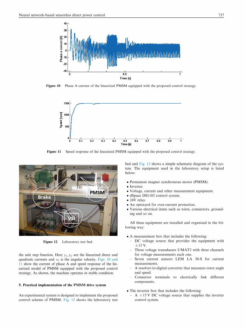
Figure 10 Phase A current of the linearized PMSM equipped with the proposed control strategy.
Figure 11 Speed response of the linearized PMSM equipped with the proposed control strategy.
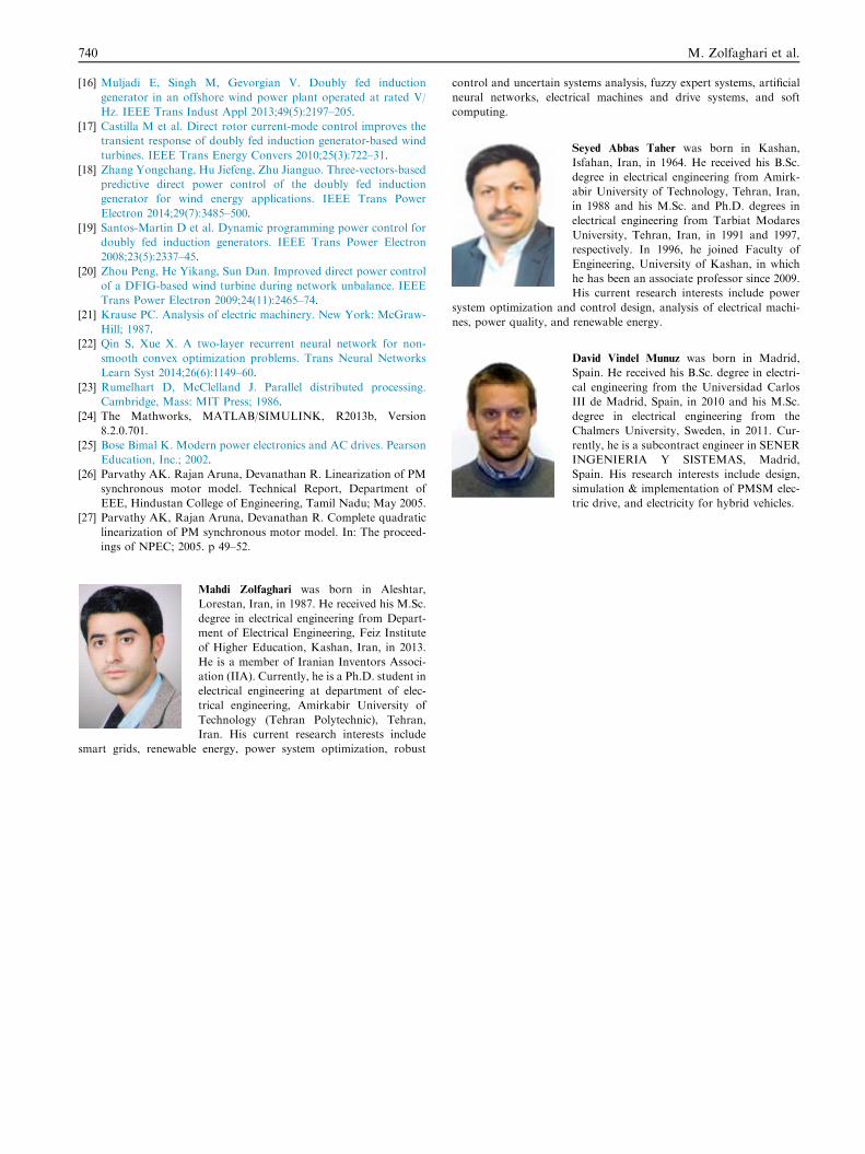
Figure 12 Laboratory test bed.
Neural network-based sensorless direct power control 737
the unit step function. Here y1; y2 are the linearized direct andquadratic currents and x3 is the angular velocity. Figs. 10 and11 show the current of phase A and speed response of the lin-
earized model of PMSM equipped with the proposed controlstrategy. As shown, the machine operates in stable condition.
5. Practical implementation of the PMSM drive system
An experimental system is designed to implement the proposed
control scheme of PMSM. Fig. 12 shows the laboratory test
bed and Fig. 13 shows a simple schematic diagram of the sys-tem. The equipment used in the laboratory setup is listed
below:
� Permanent magnet synchronous motor (PMSM).
� Inverter.� Voltage, current and other measurement equipment.� dSpace DS1103 control system.� 24V relay.
� An optocard for over-current protection.� Various electrical items such as wires, connectors, ground-ing and so on.
All these equipment are installed and organized in the fol-lowing way:
� A measurement box that includes the following:– DC voltage source that provides the equipment with
±15 V.– Three voltage transducers UMAT2 with three channels
for voltage measurements each one.– Seven current sensors LEM LA 50-S for current
measurements.– A resolver-to-digital converter that measures rotor angle
and speed.
– Connector terminals to electrically link differentcomponents.
� The inverter box that includes the following:– A ±15 V DC voltage source that supplies the inverter
control system.

dspace
GRID
PMSM
V
A
RESOLVER
A
INVERTER
RELAY
V
V A
A&DI/O
D I/O
INVERTER BOX MEASURENENTS BOX
Figure 13 Schematic diagram of implemented drive system.
Figure 14 Experiment results: response of the speed of PMSM.
738 M. Zolfaghari et al.
– A ±24 V DC voltage source that feeds the gridcontactor.
– A four leg switch-mode inverter that uses MOSFETswitches (one leg is spare).
– A relay (C3-A 30) for the PMSM secondary windingconnection to the grid.
– A designed electronic board to drive the relay.
Figure 15 Experiment results: res
� The PMSM with double stator windings and the resolveralready installed on the shaft. Resolver coils are availablefrom the motor through a 12-pin connector installed in
the motor housing.� Control system is based on the dSpace, including the fol-lowing parts:
– Two CP1103 dSpace board with analog and digital I/O.– A CLP1103 dSpace board with luminous LEDs that
show the state of the different signals.
– The optocard that in case of over-current in invertershuts down the PWM signal to the transistors of theinverter to avoid damaging the converter.
– A DIO interface card that receives the measurement sig-nals and sends an error signal to the optocard in case ofover-currents.
The secondary winding voltages and currents are measured
by the transducers. Moreover, there is a relay for connectingthe three-phase grid voltages to the secondary set of windings.The machine used in the practical setup is a surface mounted
PMSM. The motor parameters used in the practical setupare the same as those considered in the simulations. The mag-netic flux created by the permanent magnets has a fixed value.
For PMSM, the inductances in direct and quadrature axes arethe same values.
ponse of the power of PMSM.

Table A.1 Values of the parameters of the PMSM considered
in the simulations.
Parameter Value Description
VDC 300 V DC voltage
xn 1500 rpm Rated speed
Rs 0.4 O Stator phase resistance
Ls 13 mH Stator phase inductance
P 2 Pole pairs
Tn 3 N m Rated torque
J 0.004 kg m2 Inertia
B 0.002 N m/rad/s Viscous coefficient
Neural network-based sensorless direct power control 739
Figs. 14 and 15 show the experimental results of the imple-mented PMSM drive. As shown, noting to Fig. 4(c) and Fig. 6,
the performance of the proposed control strategy in experi-ment is good.
6. Conclusion
In this paper, the direct power control (DPC) technique forcontrolling PMSM based on a neural network based speed
estimator was presented. This proposed sensorless schemewas a new approach which employed a model reference adap-tive system (MRAS) speed observer that used the current
model as an adaptive model for DPC control PMSM drives.The nonlinear model of the motor was linearized based onquadratic linearization technique and removed the dominantquadratic nonlinearity of the model as well as higher order
terms involving the input in the system. The simulations con-firmed that the proposed control approach was able to controlthe PMSM for the linearized model as well as for the nonlinear
model of the motor. The simulation and experimental resultsconfirmed the effectiveness of this control strategy in trackingthe reference power as well as reducing the ripples.
Appendix A
A.1. Parameters values
See Table A.1.
A.2. Linearized model of PMSM
The PMSM model can be written in the standard form asfollows:
_x ¼ Axþ Buþ f2ðxÞ
x ¼ x1 x2 x3½ �T; u ¼ u1 u2½ �T; f2ðxÞ ¼k1x2x3
k2x3x1
k3x2x1
264375
where ½ x1 x2 x3 �T ¼ ½ id iq xe �T is the state vector, and
½ u1 u2 �T ¼ ½ vqs vds �T; and k1; k2; k3 are constants defined
in the literature. Applying the quadratic linearization theoremto this model, the linearized model of PMSM becomes
uðxÞ ¼ uð2ÞðxÞ ¼0
k1x2x3
k1x23
264375; aðxÞ ¼ �k3x2x1
�k2x3x1
� �
bðm�1ÞðxÞ ¼ ð�1Þðm�1ÞBT @u
ð2ÞðxÞ@x
B
� �ðm�1Þ;m P 2
Thus, the system can be reduced to
_y ¼ Ayþ Bv
References
[1] Lee Kwang-Woon, Park Sungin, Jeong Seongki. A seamless
transition control of sensorless PMSM compressor drives for
improving efficiency based on a dual-mode operation. IEEE Trans
Power Electron 2015;30(3):1446–56.
[2] Banerjee Abhik, Mukherjee V, Ghoshal SP. Intelligent controller
for load-tracking performance of an autonomous power system.
Ain Shams Eng J 2014;5(4):1167–76.
[3] Behjat Vahid, Hamrahi Mehrdad. Dynamic modeling and
performance evaluation of axial flux PMSG based wind turbine
system with MPPT control. Ain Shams Eng J 2014;5(4):1157–66.
[4] Hu Jiefeng, Zhu Jianguo, Zhang Yongchang, Platt G. Predictive
direct virtual torque and power control of doubly fed induction
generators for fast and smooth grid synchronization and flexible
power regulation. IEEE Trans Power Electron 2013;28
(7):3182–94.
[5] Casadei D, Serra G, Tani A. Implementation of a direct torque
control algorithm for induction motors based on discrete space
vector modulation. IEEE Trans Power Electron 2000;15
(4):769–77.
[6] Kazmierkowski MP, Krishnan R, Blaabjerg F. Control in power
electronics-selected problems. Academic Press; 2002, ISBN 0-12-
402772-5, ch.3.
[7] Rijcke SD, Ergun H, Van Hertem D, Driesen J. Grid impact of
voltage control and reactive power support by wind turbines
equipped with direct-drive synchronous machines. IEEE Trans
Sustain Energy 2012;3(4):890–8.
[8] Tremblay E, Atayde S, Chandra A. Comparative study of control
strategies for the doubly fed induction generator in wind energy
conversion systems: a dsp-based implementation approach. IEEE
Trans Sustain Energy 2011;2(3):288–99.
[9] Shuhui L, Haskew TA, Williams KA, Swatloski RP. Control of
DFIG wind turbine with direct-current vector control configura-
tion. IEEE Trans Sustain Energy 2012;3(1):1–11.
[10] Giraldo E, Garces A. An adaptive control strategy for a wind
energy conversion system based on PWM-CSC and PMSG. IEEE
Trans Power Syst 2014;29(3):1446–53.
[11] Muyeen SM, Takahashi R, Murata T, Tamura J. A variable speed
wind turbine control strategy to meet wind farm grid code
requirements. IEEE Trans Power Syst 2010;25(1):331–40.
[12] Genduso Fabio et al. Back-EMF sensorless control algorithm for
high dynamics performances PMSM. IEEE Trans Indust Electron
2010;57(6):2092–100.
[13] Mohammadi J et al. A combined vector and direct power control
for DFIG-based wind turbines. IEEE Trans Sustain Energy
2014;29(3):767–75.
[14] Chilipi RR, Singh B, Murthy SS. Performance of a self-excited
induction generator with DSTATCOM-DTC drive-based voltage
and frequency controller. IEEE Trans Energy Convers 2014;29
(3):545–57.
[15] Nian Heng, Song Yipeng. Direct power control of doubly fed
induction generator under distorted grid voltage. IEEE Trans
Power Electron 2014;29(2):894–905.
740 M. Zolfaghari et al.
[16] Muljadi E, Singh M, Gevorgian V. Doubly fed induction
generator in an offshore wind power plant operated at rated V/
Hz. IEEE Trans Indust Appl 2013;49(5):2197–205.
[17] Castilla M et al. Direct rotor current-mode control improves the
transient response of doubly fed induction generator-based wind
turbines. IEEE Trans Energy Convers 2010;25(3):722–31.
[18] Zhang Yongchang, Hu Jiefeng, Zhu Jianguo. Three-vectors-based
predictive direct power control of the doubly fed induction
generator for wind energy applications. IEEE Trans Power
Electron 2014;29(7):3485–500.
[19] Santos-Martin D et al. Dynamic programming power control for
doubly fed induction generators. IEEE Trans Power Electron
2008;23(5):2337–45.
[20] Zhou Peng, He Yikang, Sun Dan. Improved direct power control
of a DFIG-based wind turbine during network unbalance. IEEE
Trans Power Electron 2009;24(11):2465–74.
[21] Krause PC. Analysis of electric machinery. New York: McGraw-
Hill; 1987.
[22] Qin S, Xue X. A two-layer recurrent neural network for non-
smooth convex optimization problems. Trans Neural Networks
Learn Syst 2014;26(6):1149–60.
[23] Rumelhart D, McClelland J. Parallel distributed processing.
Cambridge, Mass: MIT Press; 1986.
[24] The Mathworks, MATLAB/SIMULINK, R2013b, Version
8.2.0.701.
[25] Bose Bimal K. Modern power electronics and AC drives. Pearson
Education, Inc.; 2002.
[26] Parvathy AK. Rajan Aruna, Devanathan R. Linearization of PM
synchronous motor model. Technical Report, Department of
EEE, Hindustan College of Engineering, Tamil Nadu; May 2005.
[27] Parvathy AK, Rajan Aruna, Devanathan R. Complete quadratic
linearization of PM synchronous motor model. In: The proceed-
ings of NPEC; 2005. p 49–52.
Mahdi Zolfaghari was born in Aleshtar,
Lorestan, Iran, in 1987. He received his M.Sc.
degree in electrical engineering from Depart-
ment of Electrical Engineering, Feiz Institute
of Higher Education, Kashan, Iran, in 2013.
He is a member of Iranian Inventors Associ-
ation (IIA). Currently, he is a Ph.D. student in
electrical engineering at department of elec-
trical engineering, Amirkabir University of
Technology (Tehran Polytechnic), Tehran,
Iran. His current research interests include
smart grids, renewable energy, power system optimization, robust
control and uncertain systems analysis, fuzzy expert systems, artificial
neural networks, electrical machines and drive systems, and soft
computing.
Seyed Abbas Taher was born in Kashan,
Isfahan, Iran, in 1964. He received his B.Sc.
degree in electrical engineering from Amirk-
abir University of Technology, Tehran, Iran,
in 1988 and his M.Sc. and Ph.D. degrees in
electrical engineering from Tarbiat Modares
University, Tehran, Iran, in 1991 and 1997,
respectively. In 1996, he joined Faculty of
Engineering, University of Kashan, in which
he has been an associate professor since 2009.
His current research interests include power
system optimization and control design, analysis of electrical machi-
nes, power quality, and renewable energy.
David Vindel Munuz was born in Madrid,
Spain. He received his B.Sc. degree in electri-
cal engineering from the Universidad Carlos
III de Madrid, Spain, in 2010 and his M.Sc.
degree in electrical engineering from the
Chalmers University, Sweden, in 2011. Cur-
rently, he is a subcontract engineer in SENER
INGENIERIA Y SISTEMAS, Madrid,
Spain. His research interests include design,
simulation & implementation of PMSM elec-
tric drive, and electricity for hybrid vehicles.